ALTERNATE CURRENT CALL SYSTEMS - FARFISA
195
TECHNICAL MANUAL 2004 ALTERNATE CURRENT CALL SYSTEMS
-
Upload
khangminh22 -
Category
Documents
-
view
1 -
download
0
Transcript of ALTERNATE CURRENT CALL SYSTEMS - FARFISA

TECHNICALMANUAL2004
ALTERNATECURRENTCALL SYSTEMS

INTRODUCTION
This edition contains helpful information on the operation and installa-tion of Farfisa video intercoms systems.
In order to make the systems work properly it is necessary to install onlyFarfisa equipment, keeping strictly to the items referred to in eachdiagram.
Read all the notes carefully, (even the small ones) in each installationscheme and the working instructions of the system given in thefollowing pages.
For the sake of clarity, please notice that the sequence of the terminalsof each article has not been followed. Only the terminal code (letter and/or number) is valid not the graphic sequence.
The items may have more terminals than the ones in the installationdiagrams. The excess terminals must not be used.
Italian Association of Electrotechnical andElectronic Industries
Mark of VDE a German Testing and Certi-fication Institute.
Quality assured firm.
Notice to the installer and user
Check the integrity of the product after removing it from the packing.
Packing materials (such as plastic bags, cardboard, polystyrenefoam, etc.) must be kept out of the reach of children.
The manufacturer cannot be held responsible for possible damagescaused by improper, erroneous and unreasonable use.
The cable runs of any intercom and video-intercom system must bekept separate from the mains or any other electrical installation asrequired by International Safety Standards.
WARNINGS
An all-pole mains switch with a contact separation of at least3mm in each pole shall be incorporated in the electrical installa-tion of the building.
Before connecting the unit, make sure its data correspond tothose of the mains.
The apparatus shall not be exposed to dripping or splashing.
For correct operation make sure that ventilation or heat dissipa-tion openings are not obstructed.
Do not open or tamper with power supply or video intercomapparatus when they are ON. There is high voltage inside.
Avoid bumping and hitting the video intercom apparatus, itcould break of the CRT with consequent projections of frag-mented glass.
For installation or maintenance refer only to qualified person-nel.
CE MARK
The CE mark ensures that the product complies with the requirements of theEuropean Community Directives in force; in particular, Electrical Safety LVD73/23,Electromagnetic Compatibility EMC89/336 and Telecommunication TerminalsR&TTE99/5 Directives.As set forth by the Directives, the technical documentation and Conformity Decla-rations are available in the Company’s offices for verifications and controls bycompetent Authorities.
European Mark of conformity to the EECDirectives.
SGS
ISO
90
01:2000
SY
STEM CERTIFICATION

1(MT12 - Gb2004)
INDEX
Installation instructions
Intercoms- Internal stations- External door stations- Power supplies- Service modules- Installation instructions- Installation diagrams
Video Intercoms- Internal stations- External door stations- Power supplies, control units and service modules- Installation instructions- Installation diagrams
Telecommunication- Internal stations- Intercom-telephone interface- Electronic PABX- Installation instructions- Installation diagrams
Product List
TECHNICAL MANUAL2004 edition12
Page
2
347
24252629
717281909195
149150162164170173
192

2(MT12 - Gb2004)
The Farfisa alternate call system allows for therealisation of intercom, video intercom, digitaland intercom-telephone systems.The modularity of Farfisa indoor and outdoordevices allows for system extension to satisfythe most diverse user’s requirements, fromindividual houses to apartment buildings, fromsimple intercoms to complete video intercom-telephone sets.
Selecting the systemThe Farfisa alternate call system allows for therealisation of different types of installation.
• Intercom systems• Video intercom systems• Intercom-telephone systems• Video intercom systems• Mixed systems (intercom/video intercom/
telephone)
Intercom systemsIt is the simplest of the installations. It providesbidirectional audio communication betweenintercoms and external door stations with door-opening function. The following variants of thebasic installation are possible:- intercommunicating service. It allows forcommunication between different intercomsof the same apartment or between differentapartments with private conversation to otherusers and to external stations.
-private conversation. By adding a board toeach intercom you can restrict the communi-cation between internal and external user tothe called user. The other users do not hearthe conversation in progress when they lift thehandset.
For the realisation of a basic intercom systemyou need 4 common wires + 1 single for eachuser.
Video intercom systemsApart from audio communication and door-opening function, video intercom systems pro-vide visual control of the entrance. The typicalcharacteristics of video intercom systems are:- Timed operation. The video intercom of thecalled user is enabled for about 40 seconds.The time doubles if the handset is lifted. Thesystem returns to the stand-by state when thehandset is replaced.
-Private conversation. Video intercom sys-tems allow for audio communication only forthe called user. The other users do not hearthe conversation in progress when they lift thehandset.
- Intercommunicating service. This serviceallows for audio communication between dif-ferent intercoms or video intercoms of thesame apartment or between different apart-ments with private conversation to other usersor external stations.
-Control switching ON. The user can enablethe system, switch ON his/her own video inter-com and monitor the area framed by the cam-era. Additional wires and activation buttonsare needed in case of multiple entrances.
INSTALLATION INSTRUCTIONSINT
ER
CO
MS
* VID
EO
INT
ER
CO
MS
* TE
LE
CO
MM
UN
ICA
TIO
N
For the realisation of basic video intercomsystems you need 7 common wires + 1 singlefor each user + common coaxial cable.
Intercom-telephone and video intercom-telephone systemsIt is a variant of traditional intercom and videointercom systems in which internal stations usetelephones (with monitors for video intercom-telephone functions) instead of intercoms orvideo intercoms. In this case intercom connec-tions are established over an interface boardthat provides telephone and intercom commu-nication. The interface can be a stand aloneproduct (art. FT11D) or an interface board tobe installed inside the FT105P or FT208Pelectronic PABX (art. ES60 or ES65).Internal stations can use:-a standard telephone in which intercom func-tions are obtained by dialling specific codeson the keypad
-an intercom-telephone set (art.ST740) orvideo intercom-telephone set (art.ST740 +ST7100) with telephone functions and spe-cific buttons for the main intercom services.
In intercom-telephone systems the intercom-municating service can be realized by meansof a PABX that allows also for private conver-sation.Intercom-telephone systems need 4 commonwires + 1 single for each user (+ 3 commonwires + common coaxial cable or twisted pair incase of video intercom-telephone systems) forconnections to the riser. Telephone connec-tions are made with a telephone pair.
Mixed systems (intercom/intercom-tele-phone/video intercom-telephone)All intercom, intercom-telephone and videointercom-telephone systems can be combinedaccording to the user’s requirements.
Choosing the correct articleWhen choosing the article and type of instal-lation, you should consider:
• user’s requirements• number of users• installation possibilities• possible location of articles.
The following options are possible for externaldoor stations:• Mody series push-button panels for inter-
com, telephone and video intercom sys-tems
• Matrix series stainless steel push-buttonpanels for intercom, telephone and videointercom systems
• Prestige series brass push-button panelsfor intercom, telephone and video intercomsystems
• ErreP/R series push-button panels for inter-com and telephone systems
• TM series push-button panels for intercomand telephone systems
• UP series push-button panels for analogueintercom and telephone systems with maxi-mum 2 calls
The following options are possible for internalstations:• Studio modular line for intercom-telephone
and video intercom-telephone systems• Project line for intercom and video intercom
systems• PuntoVirgola for intercom and video inter-
com systems• Slim (900) line for intercom systems
Speaker
Microphone
Button
Resistance
Lamp
Optional wire (usually control switch-ing ON, door release button or inter-communicating calls)
Dashed line (for schematic purposesthe first and last monitors are shown inthe multi-family systems. Requiredadditional monitors can be inserted insuch dashed line to complete the in-stallation).
Diode
Electronic ringer or buzzer
Coaxial cable
xnx2 Call wires (second and last)
Telephone pair
Electric door lock
Graphic symbols
The following symbols are used in the installa-tion diagrams:
Mechanical buzzer

3(MT12 - Gb2004)
INTERCOMSTechnical manual 12 Edition 2004
INDEX
Internal stations
- Project series intercoms
- PuntoVirgola series intercoms
- Slim (900) series intercoms
External door stations
- Mody series push-button panels
- Matrix series push-button panels
- ErreP/R series push-button panels
- UP series push-button panels
Power supplies
Service modules
Installation instructions
Working instructions
Troubleshooting
Basic installation diagrams
- Si 11MO/1 Intercoms connected to 1 external door station
- Si 11MO/2 Intercoms with private conversation connected to 1 external door station
- Si 12MO/1 Intercoms connected to 2 automatically switched external door stations
- Si 13MO/1 Intercoms connected to 3 automatically switched external door stations
- Si 16MO/1 Intercom system with secondary door stations and 1 main common station (multiple entrance)
- Si 16MO/2 One-way intercom system with secondary door stations and 1 main common station (multiple entrance)
- Si 17MO/1 Intercom system with secondary door stations and 2 main common stations (multiple entrance)
Intercommunicating installation diagrams
- Si 100L/2 2 intercommunicating intercoms
- Si 100L/11 Intercommunicating intercoms (2 to 11 users)
- Si 115L/5S 5 intercommunicating intercoms connected to 1 external door station with single calls. Electronic bell for internal calls.
- Si 111L/5M 5 intercommunicating intercoms connected to 1 external door station with common call. Electronic bell for internal calls.
- Si 125L/5S 5 intercommunicating intercoms connected to 2 external door stations with single calls. Electronic bell for internal calls.
- Si 121L/5M 5 intercommunicating intercoms connected to 2 external door stations with common call. Electronic bell for internal
calls.
- Si 135L/5S 5 intercommunicating intercoms connected to 3 external door stations with single calls. Electronic bell for internal calls.
- Si 131L/5M 5 intercommunicating intercoms connected to 3 external door stations with common call. Electronic bell for internal
calls.
- Si 161L/1S One-way intercommunicating system with secondary door stations and 1 main common station (multiple entrance)
- Si 11MO/3 Multi-way intercom system connected to 1 external door station. With intercommunication service in 1 or more
apartments and private conversation feature with the external door station and the other apartments.
Application diagrams
- multi-way intercommunicating services
- one-way intercommunicating services
- one-way intercommunicating services in apartment building systems
Page
4
4
6
6
7
7
16
22
23
24
25
26
27
28
29
31
33
35
37
39
41
43
44
45
45
47
49
51
53
55
57
59
61
62
62
66
68
INT
ER
CO
MS
* VID
EO
INT
ER
CO
MS
* TE
LE
CO
MM
UN
ICA
TIO
N

4(MT12 - Gb2004)
INT
ER
CO
MS
* VID
EO
INT
ER
CO
MS
* TE
LE
CO
MM
UN
ICA
TIO
N
PT520. Two-colour intercom for 4+1 systemsconnected to one or more door stations. Com-plete with buzzer, spiral cord, electronic micro-phone and two push-buttons that can be in-creased to 10 by adding the individual push-button unit, art.PT501. It can be installed on thewall with screws or on a back box.
PT520W. Colour: white.
Terminals1 microphone2 loudspeaker3 ground5 door release push-button (max 1A)6 buzzer (0.2A)7 common push-buttons ( and 1)9 electronic bell inputP1 service push-button (max 1A)P2 ÷ P9 service push-buttons (max 0.5A)
INTERNAL STATIONS
INTERCOMS PROJECT series
Fittings for PT520 and PT520W intercoms
PT501. Individual push-button unit.
NoteWe recommend to insert the LED module PT502and bell silencer module PT515 in the bottom 2slots marked by and .To insert them properly it's necessary to removethe guide of the button sliding from the internal sideof the base cover (see figure).
PT502. Led module.
PT515. Bell silencer module (privacy).
P2
P7
P9
P8
2
W1
1
7
L+
L-
RL 36. Relay module. When installed insideintercoms it allows to activate additional bells(see page 27). Maximum switching current is1A (24V).
TerminalsC common terminal of relayNA normally open contact of relayNC normally closed contact of relay- ground
13Vac/dc voltage inputEC relay activation input (ground command)
Wires9 electronic call input without resistive load3 ground
ONOFF
PT515
6 3
L-
L+
call push-button
intercom
PROJECT
3 "8/
32
8
"
"
16
16
/
/
13
1
8672
214

5(MT12 - Gb2004)
INT
ER
CO
MS
* VID
EO
INT
ER
CO
MS
* TE
LE
CO
MM
UN
ICA
TIO
NINTERNAL STATIONS
INTERCOMS PROJECT series
21
36
2 9 1 6 3 5 7
CB9 X2
7
X1
9
PT510. Two-colour intercom for 4+1 systemsconnected to one or more door stations. Com-plete with push-button, spiral cord, buzzer, elec-tronic microphone. Wall-mounted with screwsor fixed to back box.
PT510N. Colour: beige.PT510W. Colour: white.
PT524W. White colour finish with carbon mi-crophone.
Terminals1 microphone2 loudspeaker3 ground5 door release push-button (max 1A)6 buzzer (0.2A)9 electronic bell input
Two of the followingmodules can be si-multaneously appliedinside the intercoms:- RL36 relay module;- SM50 private con-versation module;
- SR40 electronic bellmodule;
- SR41 electronicbuzzer module.
6
W1
2 9 1 3 5 7
+
-9
7
SR40. Electronic bell module (see inter-communication diagrams).
Terminals power supply call in-put (12Vac-0.5A)
X1 power supply input(12Vac-0.3A)
X2 call input (ground con-trol)
SR41. Electronic buzzer module. It can beused to differentiate calls from external doorstations or external door station andintercommunicating stations (in thiscase it can replace electronic bellmodule SR40).
Terminals4 power supply input (13Vac-70mA;
9÷20Vdc-15mA)3 ground
SM50. Private conversation module (seepages 32 and 100).
TerminalsC audio line receiverB audio line transmitter- ground
PT538. Table adapter for Project series in-tercoms, with weighted base, junction box and2.4m connection cable with 13 wires.
RL36or
SM50or
SR40or
SR41
PT501
PT502
PT515
2 1 3 6C
B
SM 50
R1
10K
9 7
23 1 5 P16
X2
7
X1
9
PT501
43
PROJECT

6(MT12 - Gb2004)
INT
ER
CO
MS
* VID
EO
INT
ER
CO
MS
* TE
LE
CO
MM
UN
ICA
TIO
N
INTERNAL STATIONS
INTERCOMS PuntoVirgola series
2 "8/3
60
1 "8/7
48
8 "8/7
225
1 "16/13
46
2 "8/5
66
8 "8/7
225
924W. Beige intercom for 4+1 systems con-nected to 1 or more door stations. Completewith a push-button, spiral cord, electronic mi-crophone, buzzer.It can be installed on the wall with screws.
Terminals1 Microphone2 Loudspeaker3 Ground5 Door release push-button (1A max)6 Buzzer (0.2A)9 Electronic bell input (from PRS240 or digital
systems)
910W. Open-voice, white, two-way model for4+1 systems connected to one or more doorstations, with internal amplification and modu-lated electronic bell and knob for adjusting thevolume (receiving channel). This model is pro-vided with two push-buttons (one for connect-ing the audio line and the other one for theelectric door lock). To optimise speech qualitythe use of 337C electric speaker is recom-mended. It can be installed on the wall withscrews or on a wall box.
TerminalsThe same of 924 series.
3 "4/1
83
2 "8/3
60
3 "4/1
83
6 "16/9
166
5
6
3 1 9 2
PV100. Two-colour intercom for 4+1 systemsconnected to one or more door stations. Com-plete with a push-button, spiral cord, built-inelectronic bell, electronic microphone. Wall-mounted with screws or fixed to back box.
PV100W. Colour: white.
Terminals1 Microphone2 Loudspeaker3 Ground5 Door release push-button (1A max)6 Buzzer (0.35A)9 Electronic bell input
9 2 1 6 5 3
205
53
1285 "
16/1
32 ""1616 // 11
8 "16/1
78
INTERCOMS 900 series (Slim) OPEN VOICE 900 series
PV-900

7(MT12 - Gb2004)
Push-button panels in extruded aluminium made upof modular elements. Suitable for the most diverseinstallation requirements.
MD71. 72. 73. 74. Plastic back boxes complete withmodule frames.
MD81.82.83.804.84.86.808.89.812. Aluminiumhood covers. To be added to MD71.72.73.74 backboxes.
MD91.92.93.904.94.96.908.99.912. Anodizedaluminium rain shelters with module frames. Usedfor wall mounting.
MD 71 MD 72 MD 73 MD 74
MD 81 MD 83 MD 804MD 82 MD 86 MD 808MD 84
MD 904MD 93MD 92MD 91
Rain shelters with module frames
Hood covers
Module frames complete with back box
PUSH-BUTTONS MODY series
EXTERNAL DOOR STATIONS
MD 94 MD 96 MD 908 MD 99 MD 912
INT
ER
CO
MS
* VID
EO
INT
ER
CO
MS
* TE
LE
CO
MM
UN
ICA
TIO
N
MODY
MD 812MD 89
8 "8/3
64
19
124
304.5
395
213
121.5
4 "16/13
12 "
15 "16/9
4 "8/7
2 "2/1
"4/
3
9 "8/1
12
16
"
"
16
16
/
/
11
5
151
5 "16/15
5 "2/1
323
414.5
140
231.5
276
10 "8/7
1 "16/9
1 "
401
15 "16/13
40
25
12
16
"
"
16
16
/
/
11
5
323
414.5
323
414.5
231.5 9 "8/1
12
16
"
"
16
16
/
/
11
5
151
5 "16/15
5 "2/1
140
3 "8/1
80
2 "16/9
65
401
15 "16/13
276
231.5
323
414.5
10 "8/7
16 "16/5
12 "16/11
9"
8/1

8(MT12 - Gb2004)
PUSH-BUTTONS MODY series
In any button module, in order to avoid thedismounting of name holder, insert a 3MAx12screw in the holes shown in the picture for eachname plate to be blocked. Screws are notsupplied by the manufacturer.
Dismounting of name holder to insert namelabel.
MD 10without call buttons
MD 111 call button
MD 122 call buttons
1 row push-button modules
Modules for electric door speaker (amplifier)
Button modules
MD 222 call buttons
MD 244 call buttons
MD 233 call buttons
MD 211 call button
2 row push-button modules
MD 1222 call buttons
MD 1244 call buttons
ELECTRIC DOOR SPEAKER
MD 30.It consists of a double amplifier (receiver andtransmitter) with adjustable volume of 2 chan-nels. Also fittable to Prestige and ErreP/Rseries push-button panels (for ErreP/R doorstations by means of 299/1 adapter).
Terminals1 audio receiver2 audio transmitter3 positive power supply 6 ÷ 8Vdc - 60mA4 ground
Dismounting and protection of name la-bels
MD 2222 call buttons
MD 2244 call buttons
MD 2266 call buttons
MD 2288 call buttons
MD20blank module
Modules: blank, number, access control and cameras
2
8
5
0
3
9
B
6
1
7
A
4
FC52P. Keypadmodule for accesscontrol (see page 9).
MD50number module
50
MD41. MD41D. Blackand white cameras.MD41C. Colour cameras(see characteristics onpage 81).
Button modules
Modules for electric door speaker (amplifier)Receiving volume adjustment
Transmitting volumeadjustment
EXTERNAL DOOR STATIONSINT
ER
CO
MS
* VID
EO
INT
ER
CO
MS
* TE
LE
CO
MM
UN
ICA
TIO
N
MODY
FP52. Proximityreader for access con-trol (see page 9).
MD 100Amplified door sta-tion with 1 push-but-ton (see page 9)
MD 200Amplified door sta-tion with 2 push-but-tons (see page 9)
3 "16/9
91
1 "
25.5
2 "16/3
55

9(MT12 - Gb2004)
INT
ER
CO
MS
* VID
EO
INT
ER
CO
MS
* TE
LE
CO
MM
UN
ICA
TIO
N
MODY
1 21 2
AMPLIFIED DOOR STATIONS
MD 100. 1 button module.Fittable in all intercom, telephone, intercommu-nicating and video intercom systems.Complete with electric door speaker amplifiedin the two channels, receiving adjustable vol-ume, call button and anodized aluminium frontplate. It can replace the MD11 and MD30 mod-ule and use all the other accessories of theMody series.
MD 200. 2 buttons module.
Terminals- ground
supply 13Vac - 0.13A1 audio receiver2 audio transmitterC call push-buttons common
call push-buttonsname-plate lamp (24V-70mA)
1 Lamp terminals2 Push-button terminal board3 Common contact of call push-buttons4 Terminals on stair light push-button5 External volume adjustment6 Terminal board for connection to the system
2
3
4
56
1
ACCESS CONTROL KEYPAD
FC52P.Access control keypad with 12 keys and 2relays for lock release. 4 programmable ac-cess codes for each relay. Programmable dooropening time from 1 up 99 sec. for each relay(or bistable operation of relay 1). Acoustic andvisual confirmation for entered keys, acceptedprogramming and for wrong codes.
Technical dataPower supply: 12Vac/dc ±10%Stand-by current: 0.015AMaximum current consumption: 0.1AContact ratings: 12Vac-5ANumbers of codes for relays 1: 4Numbers of codes for relays 2: 4 or direct
activationActivation time for each relay: from 1 to 99sec. (or bistable relay 1)Operating temperature: 0° ÷ +40°CMaximum permissible humidity: 85% RH
Terminals1 normally closed contact of relays 22 normally open contact of relays 23 common contact of relays 24 normally closed contact of relays 15 normally open contact of relays 16 common contact of relays 17 ground or alternate voltage input8 positive or alternate voltage input9-10 connection to optional door lock release
Example of composition
PUSH-BUTTONS MODY series
EXTERNAL DOOR STATIONS
Installation diagramsFor the installation of the MD100 and MD200modules see the installation diagrams for sys-tems with one entrance in the “intercom” and“video intercom” section (for example pages30, 32, 46, 48, 98, 102, 120, 178 and 180).
10 9 8 7 6 5 4 3 2 110 9 8 7 6 5 4 3 2 1
12Vac12Vdc
doorrelease
relay 1 relay 2
PROXIMITY READER FOR ACCESSCONTROL
FP52.This article allows for the activation of 2 relaysby means of keytags or electronic ISO cardsbased on transponder technology.Programmable activation time from 1 to 63seconds for every relay. 4 user cards and 1master card supplied with the product. Acousticand visual control signals and 3-digit display toview numbers and codes during set-up andoperation.
Technical dataPower supply 12Vac/dc ±10%Stand-by current 0.1AMaximum current consumption 0.25AContact ratings 24Vac - 2AMax. number of cards 490Max. number of Master cards 10Number of relays 2Relay time 1 to 63 sec.Minimum recognition distance 3 cmMaximum recognition time 1 sec.Operating temperature 0° ÷ +40°CMaximum permitted humidity 85% RH
Terminals+/A positive or alternate current input-/A ground or alternate current inputPB door open buttonNC2 normally closed contact of relay 2NA2 normally open contact of relay 2C2 common terminal of relay 2NC1 normally closed contact of relay 1NA1 normally open contact of relay 1C1 common terminal of relay 1
Card recognition LED. It turns ON duringcard recognition.
Relay activation LED. It indicates relay de-activation (red) or activation (green).
Program LED. It turns ON during systemprogramming.
Card cancellation and system setup LED.It turns ON during Master or user card can-cellation and system setup.
"4/
3
4 "8/7
45124
90
1
"16/9
"4/3
19
3
1
7
A
4
2
8
5
0
3
9
B
6
"16/
14 "8/
7
52124
90
2
"16/9
"4/3
19
3

10(MT12 - Gb2004)
PUSH-BUTTONS MODY series
Place the box of the push button panel at aheight of about 1.65m (5' 5") from the floorkeeping the front edges flush-mounted andvertical to the finished plaster.
Insertion of cable bush between back boxes.The cable bushes must be inserted beforebrickwork.
Openings for cables.
Flush mounting and cables placing.
Mounting of button module.
Lower fixing of the module frame.
(a)
Lower fixing of the module frame on back box.It is advised to insert a protection (a) betweenpanel and wall while fixing.
EXTERNAL DOOR STATIONSINT
ER
CO
MS
* VID
EO
INT
ER
CO
MS
* TE
LE
CO
MM
UN
ICA
TIO
N
MODY
aaaaaaaaaaaaa
5 ' 5 "

11(MT12 - Gb2004)
PUSH-BUTTONS MODY series
Mounting of frame bottom and door speaker(amplifier).
Top fixing of the panel.
Alignment of the panel.
Hood covers
Dismounting of the frame top side from the rainshelter.
Fixing of the hood cover between the back boxand the module frame.
Rain shelter
Modules insertion and wall fixing of rain shelter.
Mounting of the frame top to the rain shelter.
EXTERNAL DOOR STATIONS INT
ER
CO
MS
* VID
EO
INT
ER
CO
MS
* TE
LE
CO
MM
UN
ICA
TIO
N
MODY

12(MT12 - Gb2004)
48 call buttons 62 call buttons52 call buttons 58 call buttons
35 call buttons 44 call buttons38 call buttons
PUSH-BUTTONS MODY series Example of Mody push-button panel installations.
46 call buttons41 call buttons
31 call buttons 34 call buttons
16 call buttons
11 call buttons 12 call buttons 13 call buttons
1 call button 2 call buttons
3 call buttons
10 call buttons
4 call buttons 5 call buttons 6 call buttons
7 call buttons 8 call buttons
13 call buttons 14 call buttons 11 call buttons 14 call buttons
24 call buttons23 call buttons21 call buttons19 call buttons18 call buttons17 call buttons
1 row push-buttonEXTERNAL DOOR STATIONSINT
ER
CO
MS
* VID
EO
INT
ER
CO
MS
* TE
LE
CO
MM
UN
ICA
TIO
N
9 call buttons
25 call buttons 29 call buttons28 call buttons27 call buttons
MODY

13(MT12 - Gb2004)
Button modules andnumber or blank module
Back box andmodule frame
Hoodcovers
PUSH-BUTTONS MODY series Composition board of Mody push-button panels.Rain
shelterModule forspeaker
Door speaker(amplifier)
Compositionsand dimensions
N°calls
1 MD30
1 MD30
1 MD30
1 MD30
1 MD30
1 MD30
1 MD30
1 MD30
1 MD30
1 MD30
1 MD30
1 MD30
1 MD30
1 MD30
1 MD30
1 MD30
1 MD30
1 MD30
1 MD30
1 MD30
1 MD30
1 MD30
1 MD30
1 MD30
1 MD30
1 MD30
1 MD30
1 MD30
1 MD30
1 MD30
1 MD30
1 MD30
1 MD30
1 MD30
1 MD30
1 MD30
1 MD30
1 MD30
1 MD30
1 MD30
1 MD30
1 MD30
1 MD30
1 MD30
1 MD30
1 MD30
1 MD30
1 MD30
1 MD30
1 MD30
1 MD30
1 MD11
1 MD12
1 MD10
1 MD10
1 MD11
1 MD12
1 MD10
1 MD10
1 MD11
1 MD12
1 MD10
1 MD10
1 MD11
1 MD12
1 MD10
1 MD10
1 MD11
1 MD12
1 MD10
1 MD10
1 MD11
1 MD12
1 MD10
1 MD10
1 MD11
1 MD12
1 MD12
1 MD12
1 MD12
1 MD12
1 MD11
1 MD10
1 MD11
1 MD12
1 MD10
1 MD12
1 MD11
1 MD10
1 MD11
1 MD12
1 MD11
1 MD12
1 MD12
1 MD12
1 MD10
1 MD10
1 MD11
1 MD12
1 MD11
1 MD10
1 MD12
-
-
1 MD23
1 MD24
1 MD24
1 MD24
1 MD24
2 MD24
2 MD24
2 MD24
2 MD24
3 MD24
3 MD24
3 MD24
3 MD24
4 MD24
4 MD24
4 MD24
4 MD24
5 MD24
5 MD24
5 MD24
5 MD24
6 MD24
6 MD24
6 MD24
6 MD24
6 MD24
6 MD24
7 MD24
6 MD24
8 MD24
8 MD24
8 MD24
8 MD24
8 MD24
9 MD24
9 MD24
9 MD24
9 MD24
9 MD24
10 MD24
10 MD24
11 MD24
12 MD24
12 MD24
12 MD24
12 MD24
13 MD24
14 MD24
15 MD24
1 MD71
1 MD71
1 MD72
1 MD72
1 MD72
1 MD72
1 MD73
1 MD73
1 MD73
1 MD73
2 MD72
2 MD72
2 MD72
2 MD72
2 MD73
2 MD73
2 MD73
2 MD73
2 MD73
2 MD73
2 MD73
2 MD73
2 MD74
2 MD74
2 MD74
2 MD74
2 MD74
2 MD74
2 MD74
2 MD74
3 MD73
3 MD73
3 MD73
3 MD73
3 MD74
3 MD74
3 MD74
3 MD74
3 MD74
3 MD74
3 MD74
3 MD74
3 MD74
3 MD74
4 MD74
4 MD74
4 MD74
4 MD74
4 MD74
4 MD74
4 MD74
1 MD81
1 MD81
1 MD82
1 MD82
1 MD82
1 MD82
1 MD83
1 MD83
1 MD83
1 MD83
1 MD84
1 MD84
1 MD84
1 MD84
1 MD86
1 MD86
1 MD86
1 MD86
1 MD86
1 MD86
1 MD86
1 MD86
1 MD808
1 MD808
1 MD808
1 MD808
1 MD808
1 MD808
1 MD808
1 MD808
1 MD89
1 MD89
1 MD89
1 MD89
1 MD812
1 MD812
1 MD812
1 MD812
1 MD812
1 MD812
1 MD812
1 MD812
1 MD812
1 MD812
-
-
-
-
-
-
-
1 MD91
1 MD91
1 MD92
1 MD92
1 MD92
1 MD92
1 MD93
1 MD93
1 MD93
1 MD93
1 MD94
1 MD94
1 MD94
1 MD94
1 MD96
1 MD96
1 MD96
1 MD96
1 MD96
1 MD96
1 MD96
1 MD96
1 MD908
1 MD908
1 MD908
1 MD908
1 MD908
1 MD908
1 MD908
1 MD908
1 MD99
1 MD99
1 MD99
1 MD99
1 MD912
1 MD912
1 MD912
1 MD912
1 MD912
1 MD912
1 MD912
1 MD912
1 MD912
1 MD912
-
-
-
-
-
-
-
124x121.5x19(47/
8" x 4 13/
16" x 3/
4")
124x213x19(47/
8" x 8 3/
8" x 3/
4")
248x304.5x19(9 3/
4"
x 12" x
3/
4")
248x395x19(9 3/4" x 15 9/16" x 3/4")
372x395x19(14 5/8" x 15 9/16" x
3/4")
* or MD20 or MD50 or FC52P or FP52 Optional It replacesMD71, 72, 73, 74
124x304,5x19(47/8" x 12" x 3/4")
or MD74 or MD804 or MD904
1 row push-button
1
2
3
4
5
6
7
8
9
10
11
12
13
14
15
16
17
18
19
20
21
22
23
24
25
26
27
28
29
30
31
32
33
34
35
36
37
38
39
40
41
43
45
46
48
50
52
53
55
58
62
-
-
-
-
-
-
1 MD23
-
-
-
1 MD23
-
-
-
1 MD23
-
-
-
1 MD23
-
-
-
1 MD23
-
-
-
1 MD21
1 MD22
1 MD23
-
2 MD23
-
-
-
1 MD23
2 MD21
-
2 MD21
2 MD21
2 MD21
2 MD22
1 MD21
1 MD23
-
-
2 MD21
3 MD21
3 MD21
2 MD21
1 MD22
-
-
-
-
-
-
-
-
-
-
-
-
-
-
-
1 *
1 *
1 *
1 *
-
-
-
-
1 *
1 *
1 *
1 *
-
-
-
-
-
-
-
-
2 *
1 *
2 *
-
-
-
-
-
-
-
3 *
1 *
-
-
-
-
-
EXTERNAL DOOR STATIONS INT
ER
CO
MS
* VID
EO
INT
ER
CO
MS
* TE
LE
CO
MM
UN
ICA
TIO
N
248x213x19(9 3/4" x 8 3/8" x
3/4")
MODY
496x395x19(19 1/
2" x 15 9/
16" x 3/
4")
372x304.5x19(14 5/8" x 12"
x 3/4")

14(MT12 - Gb2004)
PUSH-BUTTONS MODY series Example of Mody push-button panel installations.
2 row push-buttonEXTERNAL DOOR STATIONSINT
ER
CO
MS
* VID
EO
INT
ER
CO
MS
* TE
LE
CO
MM
UN
ICA
TIO
N
96 call buttons 124 call buttons104 call buttons 116 call buttons
70 call buttons 88 call buttons76 call buttons 92 call buttons82 call buttons
62 call buttons 68 call buttons
32 call buttons
22 call buttons 24 call buttons 26 call buttons
2 call buttons 4 call buttons
6 call buttons
20 call buttons
8 call buttons 10 call buttons 12 call buttons
14 call buttons 16 call buttons
26 call buttons 28 call buttons 22 call buttons 28 call buttons
48 call buttons46 call buttons42 call buttons38 call buttons36 call buttons34 call buttons
18 call buttons
50 call buttons 58 call buttons56 call buttons54 call buttons
MODY

15(MT12 - Gb2004)
1 MD30
1 MD30
1 MD30
1 MD30
1 MD30
1 MD30
1 MD30
1 MD30
1 MD30
1 MD30
1 MD30
1 MD30
1 MD30
1 MD30
1 MD30
1 MD30
1 MD30
1 MD30
1 MD30
1 MD30
1 MD30
1 MD30
1 MD30
1 MD30
1 MD30
1 MD30
1 MD30
1 MD30
1 MD30
1 MD30
1 MD30
1 MD30
1 MD30
1 MD30
1 MD30
1 MD30
1 MD30
1 MD30
1 MD30
1 MD30
1 MD30
1 MD30
1 MD30
1 MD30
1 MD30
1 MD30
1 MD30
1 MD30
1 MD30
1 MD30
1 MD30
PUSH-BUTTONS MODY series Composition board of Mody push-button panels.
2
4
6
8
10
12
14
16
18
20
22
24
26
28
30
32
34
36
38
40
42
44
46
48
50
52
54
56
58
60
62
64
66
68
70
72
74
76
78
80
82
86
90
92
96
100
104
106
110
116
124
1 MD122
1 MD124
1 MD10
1 MD10
1 MD122
1 MD124
1 MD10
1 MD10
1 MD122
1 MD124
1 MD10
1 MD10
1 MD122
1 MD124
1 MD10
1 MD10
1 MD122
1 MD124
1 MD10
1 MD10
1 MD122
1 MD124
1 MD10
1 MD10
1 MD122
1 MD124
1 MD124
1 MD124
1 MD124
1 MD124
1 MD122
1 MD10
1 MD122
1 MD124
1 MD10
1 MD124
1 MD122
1 MD10
1 MD122
1 MD124
1 MD122
1 MD124
1 MD124
1 MD124
1 MD10
1 MD10
1 MD122
1 MD124
1 MD122
1 MD122
1 MD124
-
-
1 MD226
1 MD228
1 MD228
1 MD228
1 MD228
2 MD228
2 MD228
2 MD228
2 MD228
3 MD228
3 MD228
3 MD228
3 MD228
4 MD228
4 MD228
4 MD228
4 MD228
5 MD228
5 MD228
5 MD228
5 MD228
6 MD228
6 MD228
6 MD228
6 MD228
6 MD228
6 MD228
7 MD228
6 MD228
8 MD228
8 MD228
8 MD228
8 MD228
8 MD228
9 MD228
9 MD228
9 MD228
9 MD228
9 MD228
10 MD228
10 MD228
11 MD228
12 MD228
12 MD228
12 MD228
12 MD228
12 MD228
12 MD228
15 MD228
1 MD71
1 MD71
1 MD72
1 MD72
1 MD72
1 MD72
1 MD73
1 MD73
1 MD73
1 MD73
2 MD72
2 MD72
2 MD72
2 MD72
2 MD73
2 MD73
2 MD73
2 MD73
2 MD73
2 MD73
2 MD73
2 MD73
2 MD74
2 MD74
2 MD74
2 MD74
2 MD74
2 MD74
2 MD74
2 MD74
3 MD73
3 MD73
3 MD73
3 MD73
3 MD74
3 MD74
3 MD74
3 MD74
3 MD74
3 MD74
3 MD74
3 MD74
3 MD74
3 MD74
4 MD74
4 MD74
4 MD74
4 MD74
4 MD74
4 MD74
4 MD74
1 MD81
1 MD81
1 MD82
1 MD82
1 MD82
1 MD82
1 MD83
1 MD83
1 MD83
1 MD83
1 MD84
1 MD84
1 MD84
1 MD84
1 MD86
1 MD86
1 MD86
1 MD86
1 MD86
1 MD86
1 MD86
1 MD86
1 MD808
1 MD808
1 MD808
1 MD808
1 MD808
1 MD808
1 MD808
1 MD808
1 MD89
1 MD89
1 MD89
1 MD89
1 MD812
1 MD812
1 MD812
1 MD812
1 MD812
1 MD812
1 MD812
1 MD812
1 MD812
1 MD812
-
-
-
-
-
-
-
1 MD91
1 MD91
1 MD92
1 MD92
1 MD92
1 MD92
1 MD93
1 MD93
1 MD93
1 MD93
1 MD94
1 MD94
1 MD94
1 MD94
1 MD96
1 MD96
1 MD96
1 MD96
1 MD96
1 MD96
1 MD96
1 MD96
1 MD908
1 MD908
1 MD908
1 MD908
1 MD908
1 MD908
1 MD908
1 MD908
1 MD99
1 MD99
1 MD99
1 MD99
1 MD912
1 MD912
1 MD912
1 MD912
1 MD912
1 MD912
1 MD912
1 MD912
1 MD912
1 MD912
-
-
-
-
-
-
-
* or MD20 or MD50 or FC52P or FP52 Optionalor MD74 or MD804 or MD904
-
-
-
-
-
-
-
-
-
-
-
-
-
-
1 *
1 *
1 *
1 *
-
-
-
-
1 *
1 *
1 *
1 *
-
-
-
-
-
-
-
-
2 *
1 *
2 *
-
-
-
-
-
-
-
3 *
1 *
-
-
-
-
-
2 row push-button
-
-
-
-
-
-
1 MD226
-
-
-
1 MD226
-
-
-
1 MD226
-
-
-
1 MD226
-
-
-
1 MD226
-
-
-
1 MD222
1 MD224
1 MD226
-
2 MD226
-
-
-
1 MD226
2 MD222
-
2 MD222
2 MD222
2 MD222
2 MD224
1 MD222
1 MD226
-
-
2 MD222
3 MD222
3 MD222
3 MD224
3 MD226
-
EXTERNAL DOOR STATIONS INT
ER
CO
MS
* VID
EO
INT
ER
CO
MS
* TE
LE
CO
MM
UN
ICA
TIO
N
MODY
It replacesMD71, 72, 73, 74
Button modules andnumber or blank module
Back box andmodule frame
Hoodcovers
Rainshelter
Module forspeaker
Door speaker(amplifier)
Compositionsand dimensions
N°calls
124x121.5x19(47/8" x 4 13/16" x 3/4")
124x213x19(47/
8" x 8 3/
8" x 3/
4")
248x304.5x19(9 3/4" x 12" x
3/4")
248x395x19(9 3/
4" x 15 9/
16" x 3/
4")
372x395x19(14 5/8" x 15 9/16" x
3/4")
124x304,5x19(47/
8" x 12" x 3/
4")
248x213x19(9 3/
4"
x 8 3/
8" x
3/
4")
496x395x19(19 1/2" x 15 9/16" x 3/4")
372x304.5x19(14 5/
8"
x 12"
x 3/
4")

16(MT12 - Gb2004)
Stainless steel anti-vandalism push-buttonpanels especially studied to withstand burglary,penetration of solids and water jets (IP 45protection degree against the penetration ofexternal solids and water; IK09 against shocks).The Matrix push-button panels include backboxes, module frames, die-cast aluminiumdecorative frames, button modules, and mod-ules with built-in speaker unit (with or withoutcamera).The careful selection of modules allows formultiple application opportunities; from one-way installations to blocks of flats; from intercomto video intercom installations.The push-button elements have been developedto allow both for horizontal and verticalconfiguration.
MA 71 MA 72 MA 73
MA 61 MA 63MA 62
Front frames
Module frames complete with back box
PUSH-BUTTONS Matrix series
EXTERNAL DOOR STATIONSINT
ER
CO
MS
* VID
EO
INT
ER
CO
MS
* TE
LE
CO
MM
UN
ICA
TIO
N
MATRIX
MA 10Pwithout call buttons
MA 11P1 call button
MA 12P2 call buttons
Modules with door speaker integrated Push-button modules
MA 222 call buttons
MA 244 call buttons
MA 20blank module
MA 42without call buttonsand with B/W camera
MA 42Cwithout call buttonsand with colour cam-era
MA 43with 1 call button andB/W camera
MA 43Cwith 1 call button andcolour camera
Video modules with door speakerintegrated
For specifications see page 86.

17(MT12 - Gb2004)
PUSH-BUTTONS Matrix series
Modules with door speaker inte-grated
MA 10P.- amplified speaker unit with volume adjust-ment of 2 channels (reception and transmis-sion)
- steel front plate- red operation LED.
MA 11P.Same as MA 10P, with call button and nameplate panel with breakproof transparent screenand green LED backlight.
MA 12P.With 2 call buttons.
EXTERNAL DOOR STATIONS INT
ER
CO
MS
* VID
EO
INT
ER
CO
MS
* TE
LE
CO
MM
UN
ICA
TIO
N
MATRIX
MA10P MA11P MA12P MA20 MA22 MA24 MA42 MA43
MA42C MA43C
1 1 1 1 1
2 2 2 2 2
3 3 3 3 3
4 4 4 4 4
- - - - - - - -
A A A A A A A A
C C C C C
P1 P1 P1 P1 P1
P2 P2 P2
P3
P4
V V
M M
H H
L- L- L- L- L-
L+ L+ L+ L+ L+
Technical characteristics of MATRIX modules terminal boards
Reception audio line
Transmission audio line
Power supply input for electric door speaker (6÷12Vdc)
Audio ground
Alternated power supply input or ground for name-plate Led
AC or DC power supply input for name-plate Led (12Vac-dc)
Call push-buttons common
Call push-button
Call push-button
Call push-button
Call push-button
Video signal output (coaxial cable)
Video ground (coaxial shield)
Positive voltage input for camera (18÷24Vdc)
Alternated power supply input or ground for service Led
AC or DC power supply input for service Led (12Vac-dc)
Audio adjustmentsIf necessary, it is possible to adjust the volumeof the 2 channels audio opportunely varying theexternal knobs.
Push-button modules
MA 20.Blank module in stanless steel.
MA 22.Module with 2 call buttons and name platepanel with breakproof transparent screen andgreen LED backlight.
MA 24.With 4 call buttons.

18(MT12 - Gb2004)
EXTERNAL DOOR STATIONSINT
ER
CO
MS
* VID
EO
INT
ER
CO
MS
* TE
LE
CO
MM
UN
ICA
TIO
N
MATRIX
PUSH-BUTTONS Matrix series
Place the box of the push button panel at aheight of about 1.65m (5' 5") from the floorkeeping the front edges flush-mounted andvertical to the finished plaster.
Insertion of spacers between backboxes. Spacers and cable bushing(not supplied with the products) mustbe inserted before brick work.
Openings for cables.
Flush mounting and cables placing.
Mounting modules.

19(MT12 - Gb2004)
EXTERNAL DOOR STATIONS INT
ER
CO
MS
* VID
EO
INT
ER
CO
MS
* TE
LE
CO
MM
UN
ICA
TIO
N
MATRIX
PUSH-BUTTONS Matrix series
Fixing of frame to back box.Align the frame beforetightening the screws.
For easier connection to the electrical system, it is recommendedto insert the metal plate supplied with the product in the back boxopening, as shown in the figure. The plate is used to hook the framewith pre-assembled modules. Leave the plate in the box to reuse itfor maintenance operations.
Connection of wires to module terminal boxes.Fixing of frame to module frame.
Apply the protection gaskets suppliedwith the product on the internal part ofthe frame openings.

20(MT12 - Gb2004)
PUSH-BUTTONS Matrix series Example of Matrix push-button panel installations.
11 call buttons
1 call button 2 call buttons
3 call buttons
10 call buttons
4 call buttons 5 call buttons 6 call buttons
EXTERNAL DOOR STATIONSINT
ER
CO
MS
* VID
EO
INT
ER
CO
MS
* TE
LE
CO
MM
UN
ICA
TIO
N
6 call buttons 7 call buttons
10 call buttons8 call buttons
12 call buttons
MATRIX 46 call buttons44 call buttons41 call buttons
40 call buttons38 call buttons35 call buttons
22 call buttons15 call buttons 18 call buttons
23 call buttons 26 call buttons 30 call buttons
31 call buttons 32 call buttons 33 call buttons 34 call buttons
14 call buttons
9 call buttons

21(MT12 - Gb2004)
1 MA11P
1 MA12P
1 MA11P
1 MA10P
1 MA11P
1 MA12P
1 MA11P
1 MA10P
1 MA11P
1 MA12P
1 MA11P
1 MA12P
1 MA11P
1 MA12P
1 MA11P
1 MA10P
1 MA11P
1 MA10P
1 MA11P
1 MA12P
1 MA11P
1 MA12P
1 MA11P
1 MA10P
1 MA11P
1 MA12P
1 MA11P
1 MA12P
1 MA11P
1 MA12P
1 MA11P
1 MA12P
1 MA11P
1 MA12P
1 MA11P
1 MA10P
1 MA11P
1 MA12P
1 MA11P
1 MA12P
1 MA11P
1 MA12P
1 MA11P
1 MA12P
1 MA11P
1 MA12P
1
2
3
4
5
6
7
8
9
10
11
12
13
14
15
16
17
18
19
20
21
22
23
24
25
26
27
28
29
30
31
32
33
34
35
36
37
38
39
40
41
42
43
44
45
46
Back box andmodule frame
Frontframes
PUSH-BUTTONS Matrix series Composition board of Matrix push-button panels.Button modules and
number or blank moduleDoor speaker
module (amplifier)Compositions
and dimensionsN°
calls
-
-
1 MA22
1 MA24
1 MA24
1 MA24
1 MA24
2 MA24
2 MA24
2 MA24
2 MA24
2 MA24
3 MA24
3 MA24
3 MA24
4 MA24
4 MA24
4 MA24
4 MA24
4 MA24
5 MA24
5 MA24
5 MA24
6 MA24
6 MA24
6 MA24
6 MA24
6 MA24
7 MA24
7 MA24
7 MA24
7 MA24
8 MA24
8 MA24
8 MA24
9 MA24
9 MA24
9 MA24
9 MA24
9 MA24
10 MA24
10 MA24
10 MA24
10 MA24
11 MA24
11 MA24
1 MA71
1 MA71
1 MA72
1 MA72
1 MA72
1 MA72
1 MA73
1 MA73
1 MA73
1 MA73
2 MA72
2 MA72
2 MA72
2 MA72
2 MA73
2 MA73
2 MA73
2 MA73
2 MA73
2 MA73
2 MA73
2 MA73
4 MA72
4 MA72
4 MA72
4 MA72
4 MA72
4 MA72
4 MA72
4 MA72
3 MA73
3 MA73
3 MA73
3 MA73
4 MA73
4 MA73
4 MA73
4 MA73
4 MA73
4 MA73
4 MA73
4 MA73
4 MA73
4 MA73
4 MA73
4 MA73
140x140x19(5 1/2" x 5 1/2" x 3/4")
140x256x19(5 1/
2" x 10 1/
16" x 3/
4")
280x374x19(11" x 14 3/
4" x 3/
4")
560x256x19(22 1/16" x 10 1/16" x 3/4")
560x374x19(22 1/
16" x 14 3/
4" x 3/
4")
140x374x19(5 1/2" x 14 3/4" x 3/4")
EXTERNAL DOOR STATIONS INT
ER
CO
MS
* VID
EO
INT
ER
CO
MS
* TE
LE
CO
MM
UN
ICA
TIO
N
280x256x19(11" x 10 1/16" x 3/4")
-
-
-
-
-
-
1 MA22
-
-
-
1 MA22
1 MA22
-
-
1 MA22
-
-
1 MA22
1 MA22
1 MA22
-
-
1 MA22
-
-
-
1 MA22
1 MA22
-
-
1 MA22
1 MA22
-
-
1 MA22
-
-
-
1 MA22
1 MA22
-
-
1 MA22
1 MA22
-
-
-
-
-
-
-
-
-
-
-
-
-
-
-
-
1 MA20
1 MA20
1 MA20
-
-
-
-
-
1 MA20
1 MA20
1 MA20
1 MA20
-
-
-
-
-
-
-
-
2 MA20
2 MA20
2 MA20
2 MA20
1 MA20
1 MA20
1 MA20
1 MA20
-
-
-
-
1 MA61
1 MA61
1 MA62
1 MA62
1 MA62
1 MA62
1 MA63
1 MA63
1 MA63
1 MA63
2 MA62
2 MA62
2 MA62
2 MA62
2 MA63
2 MA63
2 MA63
2 MA63
2 MA63
2 MA63
2 MA63
2 MA63
4 MA62
4 MA62
4 MA62
4 MA62
4 MA62
4 MA62
4 MA62
4 MA62
3 MA63
3 MA63
3 MA63
3 MA63
4 MA63
4 MA63
4 MA63
4 MA63
4 MA63
4 MA63
4 MA63
4 MA63
4 MA63
4 MA63
4 MA63
4 MA63
MATRIX
420x374x19(16 9/16" x 14 3/4"
x 3/4")

22(MT12 - Gb2004)
R14 R12 R10 R8
219
8 "8/5
313 12 "16/5
282 11 "16/1
250 9 "16/13
R P 1 2 R P 1 0 R P 8 R P 6 R P 4 R P 2 R P 1
219
8 "8/5
313 12 "16/5
282 11 "16/1
376 14 "16/13
250 9 "16/13
RP. Push-button panels with anod-ized aluminium front panel and buttons,complete with name plate lights andheight adjustable contacts to compen-sate imperfections of the wall. The elec-tric door speaker can be fitted insidethe push-button panel.The unit should be flush-mountedand the microphone should befirmly attached to the front panel toavoid feedback and to obtain thehighest audio quality.
R. Push-button panelsprovided only with buttons.An electric door speakercannot be fitted inside. Whensuch panels are installed to-gether with the previousones, a system with over 12calls is obtained (see table).
L
H
LLL
H
L L
Instructions of the various ErreP/R push-button panel series and their dimensions en mm (and inches)L and H = Dimensions of the panel l and h = Dimensions of the back-box
1 "16/9
40mm
ErreP/R
RP100. 1-button amplified door station.It is complete with an amplifier, in both chan-nels, electric door speaker, volume control ofthe receiving channel, front panel in anodizedaluminium, call button, rain shelter and nameplate light.It can be installed on the wall with expansionplugs or on a wall box.
RP200. 2-button amplified door station.
Technical dataPower supply: 13VacOperating current: 130mA
Terminals2 audio receiver1 audio transmitterC common contact of call push-buttonsP1 call push-buttonP2 call push-button- ground
alternate voltage input 13Vac
ELECTRIC DOOR SPEAKER (amplifier)
AMPLIFIED DOOR STATIONS
122
4 "16/13
164
6 "16/7
40
1 "16/9
PUSH-BUTTONS ErreP/R series
EXTERNAL DOOR STATIONSINT
ER
CO
MS
* VID
EO
INT
ER
CO
MS
* TE
LE
CO
MM
UN
ICA
TIO
N 337C. It features a double amplifier (receiverand transmitter); receiver has volume control. Itis applicable inside the RP or TM push-buttonpanels (or in other push-button panels by meansof the adaptor art.299).Provided with an electret microphone and tropi-calized speaker.
Terminals1 audio receiver2 audio transmitter3 positive power supply 6÷8Vdc -60mA4 ground
H
H
L
l l
L
Series R RP R+RP R+RP+R R+RP+R+R R+R+RP+R+R
112 (4 7/16") 224 (8 13/16") 336 (13 1/4") 448 (17 5/8") 560 (22 1/16")
R8 RP1 R8+RP1=9 2R8+RP1=17 3R8+RP1=25 4R8+RP1=33
R8 RP2 R8+RP2=10 2R8+RP2=18 3R8+RP2=26 4R8+RP2=34
R10 RP4 R10+RP4=14 2R10+RP4=24 3R10+RP4=34 4R10+RP4=44
R12 RP6 R12+RP6=18 2R12+RP6=30 3R12+RP6=42 4R12+RP6=54
R14 RP8 R14+RP8=22 2R14+RP8=36 3R14+RP8=50 4R14+RP8=64
103 (4 1/16") 215 (8 7/16") 327 (12 7/8") 439 (17 5/16") 551 (21 11/16")
218.5(8 5/
8")
250(9 13/
16")
281.5(11 1/16")
313(12 5/16")
206.5(8 1/
8")
238(9 3/
8")
269.5(10 5/8")
301(11 7/8")
h
h

23(MT12 - Gb2004)
UP
3 "16/15
100
1 "16/11
42.5
5 "16/13
148
4 "16/3
106
1 "16/13
46
5 "16/15
151
UP 100. Amplified push-button panel with 1 call button.Fittable in all 4+1 intercom and intercommunicating systems.Complete with electric door speaker amplified in the two channels,volume control of the receiving channel, front panel in anodized alu-minium with call button. Wall-mountable with expansion plugs.
UP 200. Amplified push-button panel with 2 call buttons.
External volume adjustment
Surface mounted version Flush mounted version
External volume adjustment
UP 11. Amplified push-button panel with 1 call button.Fittable in all 4+1 intercom and intercommunicating systems.Complete with electric door speaker amplified in the two channels,volume control of the receiving channel, front panel in anodized alu-minium with call button.To install it you must:- fix the back box to the wall;- install the speaker unit;- make the connections;- screw the front panel onto the back box.
UP 12. Amplified push-button panel with 2 call buttons.
Terminals- ground
13Vac-70mA voltage input1 audio receiver2 audio transmitter
WiresC yellow wire connected to call but-
ton common.
PUSH-BUTTONS UP series
EXTERNAL DOOR STATIONS INT
ER
CO
MS
* VID
EO
INT
ER
CO
MS
* TE
LE
CO
MM
UN
ICA
TIO
N
3 "16/9
90
1 "16/9
40
5 "16/7
138

24(MT12 - Gb2004)
127V
127V
0 230V 127V
230V
0 230V
The power supply is not provided with fuses,but it is protected against overloading or short-circuiting by a heat sensor (thermoprotector),to restore power, it is necessary to cut off themains voltage for about one minute. Reconnectpower after having repaired the fault.Do not obstruct the openings or the ventilationor heat ejection slots to allow the equipment tooperate correctly. The power supply can beinstalled on DIN rail or screwed to the wall.All the power supplies described in this manualreplace the corresponding ones with similarinitials. E.g.: PRS220 replaces PRS220D,PRS220K, etc. PRS226 replaces PRS226Dand PRS226K.All power supplies can provide power for amaximum of 6 24V-3W lamps for illuminatingpush-button panel name plates. For more than6 lamps, PRS210 transformer should beinstalled.
General technical dataInput voltage: 127Vac or 220-230VacWorking temperature: 0°÷+50°CMaximum of humidity: 90%RH
WarningAll power supplies in this manual can workeither 127Vac or 220-230Vac.Check carefully the right connection.
PRS 210. TRANSFORMER.
Used to power 13Vac devices; MD100, MD200,RP100, RP200, UP series amplified externaldoor stations, accessories, additional doorlocks, name plate light, etc.
Technical dataPower: 15VAOutput voltage: 13VacMaximum load: 0.7AMaximum of intermittent load: 1AHousing: DIN 3 modules AWeight: 0.42 Kg. (0.93lb)Approved by: VDE according to the Safety
Standard EN60065
POWER SUPPLIESINT
ER
CO
MS
* VID
EO
INT
ER
CO
MS
* TE
LE
CO
MM
UN
ICA
TIO
N
PRS 220. STABILIZED POWER SUPPLY.It is provided to supply 4+1 intercom systems(electric door lock, name plate lamps, electricdoor-speakers, amplifier, etc.)
Technical dataPower: 15VAHousing: DIN 4 modules AWeight: 0.45 Kg. (0.99lb)Approved by: VDE (according to the Safety
Standard EN60065)
Output terminals- Ground+ Audio line power supply 6Vdc-0.1A
Power supply 13Vac for:- name plate lamps, exchangers(continuous load 0.6A)- electric door lock and bells (intermittent load1A)
PRS226. STABILIZED POWER SUPPLY/SWITCHER.It is able to supply intercommunicating intercomsystems and to switch over automatically audioconnection of the door station and of theintercommunicating service to the intercoms.
Technical dataPower: 18VAHousing: DIN 6 modules AWeight: 0.5 Kg. (1.1lb)Approved by: VDE (according to the Safety
Standard EN60065)
Output terminals- Ground+ Audio line power supply 8Vdc-0.1AX Power supply for auxiliary services 12Vdc-
0.2APower supply 13Vac for:- name plate lamps, exchangers (continuousload 0.6A)- electric door lock and bells (intermittent load1A)
7 Power supply 13Vac for electric door lock andbells (intermittent load 1A)
A Output for call from push-button panel 13Vac-0.15A
G Audio line receiver from intercoms2 Audio line transmitter to intercomsD Audio line transmitter to electric door speakerC+ Audio line receiver from electric door speaker
PRS226E. STABILIZED POWER SUPPLY/SWITCHER.As above, with the following additional termi-nals and the modification of terminal 7.
7 Electronic bell output for intercommunicationsY Electronic bell output for push-button panel
9 Electronic call input for switching over multi-way installations
4 Relay switching common terminal controlledfrom entrance 9
4a NC relay switching controlled from entrance 94b NA relay switching controlled from entrance 9
PRS 240. STABILIZED POWER SUPPLYWITH ELECTRONIC RINGING GENERA-TOR.Power supply with modulated electronic ring-ing generator for calls. It supplies the voltagesneeded for the correct operation of intercomsystems.
Technical dataPower: 18VARinging frequency: 450Hz modulatedHousing: DIN 6 modules AWeight: 0.5 Kg. (1.1lb)Approved by: VDE according to the Safety
Standard EN60065
Output terminals- Ground+ Audio line power supply 7.2Vdc-0.1AX Power supply for aux. services 12Vdc-0.2A
Power supply 13Vac for:- name plate lamps (continuous load 0.6A)- electric door lock and bells (intermittent load1A)
C+ Modulated electronic call output 12Vpp-0.25A7 Continuous electronic call output 12Vpp-0.25A
PRS 235. POWER SUPPLY FOR SYSTEMSWITH PRIVATE CONVERSATION MOD-ULE.It may be installed with Project series intercomsfor supplying power to 4+1 systems with privateconversation module. Only the intercom whichhas been called can speak to the door station.All the other users are isolated.
Technical dataPower: 18VAHousing: DIN 6 modules AWeight: 0.5 Kg. (1.1lb)Approved by: VDE according to the Safety
Standard EN60065
Output terminals- Ground+ Audio line power supply 7.2Vdc-0.1AX Power supply for auxiliary services 12Vdc-
0.2A Power supply 13Vac for:- name plate lamps (continuous load 0.6A)- electric door lock and bells (intermittent load1A)
C+ Power supply for bells 13Vac- 0.15A
PRS210 PRS220
PRS226PRS226E
PRS235PRS240
3 "2/1
89
2 "16/9
65
4 "4/1
107.5
3 "2/1
89
2 "16/9
65
2 "8/1
54
127Vac 220-230Vac
3 "2/1
89
2 "16/9
2 "4/3
70
65

25(MT12 - Gb2004)
3 "2/
1
89
2 "16/
15
74
5 "2/
1
140
INT
ER
CO
MS
* VID
EO
INT
ER
CO
MS
* TE
LE
CO
MM
UN
ICA
TIO
N
1473. 4-CONTACT ANALOG EXCHANGER.
It is installed in intercom systems with two ormore entrances for switching the audio linesand door lock of the calling entrance. It can beinstalled on DIN bar or with two screws. Inhousing DIN bar 8 modules A.Art. 1473 completely replaces the functions ofmodels 473 and 273.
Technical dataPower supply: 13Vac; 15÷21VdcCurrent consumption: 0.1ANumber of exchanges: 4Max. switching current: 5A (50V)Housing: DIN 8 modules AOperating temperature: 0° ÷ 50°CMaximum permissible humidity: 90% RH
Terminals1 Power supply 13Vac-0.1A2 Ground3 and 4 Driver to switch the relay to “b” posi-
tion - ON position5 and 6 Driver to switch the relay to “a” posi-
tion - OFF position7, 8, 9 and 10 Common contact of relays7a, 8a, 9a and 10a OFF position of the relay
contacts7b, 8b, 9b and 10b ON position of the relay
contacts11 Ground command to switch the relay to “a”
position - OFF position12 Ground command to switch the relay to “b”
position - ON position13 Electronic call input from PRS240
SERVICE MODULES
1471. RELAY UNIT
A low voltage, low current (DC/AC) unit, it canswitch voltages up to 50V and 5A max. Usedfor auxiliary services (e.g. stair lights, call for 4or more bells, door release etc).It can be installed on DIN bar or with two screws.In housing DIN bar 3 modules A.
Technical dataPower supply: 13Vac; 12÷24VdcCurrent consumption: 0.05ANumber of exchanges: 1Switching current: 5A (50V)Housing: DIN 3 modules AOperating temperature: 0° ÷ 50°CMaximum permissible humidity: 90% RH
Terminals1 Alternate current input 13Vac-dc2 Continuous current input 21Vdc3 Negative half-wave input or ground5 Common contact of relay6 Normally open contact of relay7 Normally closed contact of relay
6
7
5
1
2
3
1472. 2-CONTACT RELAY UNIT
Same as 1471, but with 2 relays and 9S inputterminal.
Technical dataPower supply: 13Vac; 12÷24VdcCurrent consumption: 0.05ANumber of exchanges: 2Switching current: 1A (24V)Housing: DIN 4 modules AOperating temperature: 0° ÷ 50°CMaximum permissible humidity: 90% RH
TerminalsIn addition to terminals of art. 1471 you find:11 Common contact of relay 212 Normally open contact of relay 213 Normally closed contact of relay 29S Electronic call input with resistive load- Ground
3 "2/1
89
2 "16/9
65
2 "8/1
54
3 "2/1
89
2 "16/9
2 "4/3
70
65
1471E. RELAY UNIT
Same as 1471, but with 9S, 9T and 9P inputterminals. In housing DIN bar 4 modules A.
TerminalsIn addition to terminals of art. 1471 you find:9P Electronic call input without resistive load9S Electronic call input with resistive load9T Electronic call input timed operation (1 sec.)- Ground

26(MT12 - Gb2004)
INSTALLATION INSTRUCTIONS
General characteristics
- The cable runs of intercom and video intercom installations must bekept separate from the mains or any other electrical installation asrequired by the International Safety Standards and the entireinstallation must be realized in compliance with the safety rules in forcein any specific Country.
- It is necessary to provide a disconnecting and safety switch before thepower supply. Use a single general switch in case of several powersupplies (also in multiple entrance).
- Before connecting the power supply make sure that its rating datacorresponds to this of the mains.
- For electromagnetic reasons, all service modules must be installednear their power supply.
Wires1) For the correct operation of the intercom system you must choose the
correct type of cable.2) Wires must be dimensioned according to the distance of the different
devices and their current consumption.3) Do not connect wires in parallel to reach the required cross-section
(for example multi-pair telephone cables). Only use a single wire withsuitable cross-section. When using multi-core cables you must selectthem with low parasite parameters (low capacitance per metre, lowinductance over Ohm).
4) If the installation includes additional power supplies you must placethem near the device to be powered.
Background noiseTo avoid possible background noise over the speech line, it is advis-able:5) not to lay intercom or telephone cables in the same runaway as the
wires used to power alternate current loads;6) to avoid using the same multi-core cable to transmit audio signals
and alternate current power supplies (lamps, amplified external doorstations, electrical door locks). Always use separate wires for alter-nate current power supplies;
7) not to connect name-plate lamps (or other devices powered withalternate current) to terminal 4 (-) of the speaker unit; 2 wires mustoriginate from terminal - (minus sign) of the power supply, one forterminal 4 of the speaker unit and one for the lamps (or other devicespowered with alternate current);
8) for name-plate lamps, to use an additional 12Vac transformer(PRS210 type) with suitable power (consumption is 75mA for eachlamp) with 2 power supply wires separate from audio wires;
9) in case of long distances between the external door station and thelast intercom, to place the power supply near the external door stationand use a relay for the electric door lock in order to avoid alternatecurrent induction along the riser (see diagrams of lateral column).
to terminal 5 ofthe intercom
use the PRS231 orPRS240 power supplyinstead of PRS220
additionalrelay
to terminal 5 ofthe intercom
power supply in theinstallation
additionalrelay
Connection of 2 door locks with simultaneous opening(Si12MO/1).
to terminal 3 ofthe intercom
additionaltransformer
Connection of 2 door locks, one of which always activable, ina system with multiple entrance (Si16MO/1; Si 16MO/2).
to terminal 5 ofthe intercom
power supply in the installation
additionalrelay
to terminal 3 ofthe intercom
to the other stairs
power supply in the instal-lation
analogexchangerof the stair
additionalrelay
additionalrelay
ELECTRIC DOOR LOCK ACTIVATION
In case of long distances or if you want to control several door locks atthe same time, install a relay as shown in the following installationdiagrams.
Electric door lock activation by means of an additional relay
PA = door release buttonSE = electric door lock
diode(100V-1A)
INT
ER
CO
MS
* VID
EO
INT
ER
CO
MS
* TE
LE
CO
MM
UN
ICA
TIO
N
m.
50100200300400
mm²S
0.350.350.50.751
AWG
2121201816
Audio and callsDistance
WIRE CROSS-SECTION
(*) Wires in bold face type.
Door lock and ground (*)
mmØ
0.70.70.811.2
mm²S
0.75122.5 -
AWG
18161413 -
mmØ
11.21.41.6 -

27(MT12 - Gb2004)
INT
ER
CO
MS
* VID
EO
INT
ER
CO
MS
* TE
LE
CO
MM
UN
ICA
TIO
N
ADDITIONAL BELL
If the ringing volume is not sufficient or if you need to chime the call in adifferent place, you can add an additional bell enabled by a relay.
Additional bell enabled by a relay to be installed inside theintercom
12 ÷ 48Vac/dc
intercomterminals
Additional bell enabled by a relay in a DINhousing
12Vac/dc ÷ 230Vac
INSTALLATION INSTRUCTIONS
ADDITIONAL AUDIO AMPLIFIER
In intercommunicating systems with long distances between intercomsand power supply, to increase the intercommunication audio level, it isadvisable to install an amplifier art. 2443 (see page 90 for characteris-tics). The following diagram can be applied to all intercommunicatingsystems (from page 47 to page 61).
WORKING INSTRUCTIONS
Basic systems
For all the intercom systems, simply lift the handset to speak to the doorstation. The call is indicated by an audio signal (a buzzer or an electronicbell).To activate the door release, press the push-button with the key symbol.In systems with two or more entrances the communication and doorrelease are switched automatically on the entrance from which the callis made while the other entrances are isolated.
Systems with private conversation module
In all standard intercom systems (not intercommunicating) a privateaudio system can be provided (only the intercom which has been calledcan speak to the door station) by installing the “private conversationmodule" art.SM50 in every intercom.Since the buzzer rings, the user has about 30 seconds to lift handset andanswer. There is no time limit for the private conversation. When thehandset is replaced the system returns to the rest condition. If a userdoes not replace the handset properly, the next call from anotherintercom, automatically cuts him out of the audio connection with thedoor station.
Intercommunicating systems
Intercommunicating systems allow users to speak to one another bysimply lifting the handset; any user can join in to a conversation alreadyin progress. To avoid interferences it is necessary to observe thefollowing instructions.Lift the handset, make sure that there is not a conversation already inprogress, then press the call push-button corresponding to the desireduser.
Intercommunicating systems connected to door station
Such systems allow conversation between two or more inside users withthe exclusion of the door station, or between one inside user and thedoor station.When there is a call from an external push-button panel the audio line ofthe electric door speaker is activated automatically; when one calls fromone of the intercoms, the internal intercommunicating audio line isautomatically activated.The user called has simply to lift the handset.Any user can join in to a conversation already in progress.To avoid interferences it is necessary to observe the following instruc-tions:- lift the handset, make sure that there is not a conversation already inprogress, then press the call push-button corresponding to the desireduser.As it is shown in the connection diagram, internal calls have a sound(electronic) distinct from external calls (buzzer).To activate the electric lock it is necessary to push the push-button witha key symbol on. By performing this operation the system returns to theintercommunicating service with the audio exclusion of the door station.
Terminal 9 isused in theSi11MO/3diagram onpage 61 (onlyPRS226E).
intercomterminals

28(MT12 - Gb2004)
At the door station a whistle is heard(Larsen effect)The electric door-speaker (amplifier) is badlyhoused in the push-button panel; the micro-phone has to be stuck to plate. Lower thevolume.
Radio reception on the door stationThe defect can occur when there is a transmit-ter working in the proximity. Apply a condenserfrom 0.1µF between terminals 1 and 3 of theelectric door speaker (amplifier).
INTERCOMMUNICATING SYSTEMS
No sound in either channel. Intercommu-nicating phone not workingShort-circuit between + and - of the powersupply. Faulty power supply.
Calls from the door station activate. Nosounds in either channel. Intercommuni-cating phone is workingNo power supply between 3 (+) and 4 (-) of theelectric door-speaker (8Vdc). Faulty powersupply.
No sounds from the intercoms to the doorstationThe connection between 1 of the intercoms andG of the power supply has been interrupted.The connection between D of the power supplyand 1 of the electric door-speaker (amplifier)has been interrupted. Faulty electric door-speaker (amplifier). Faulty power supply.
No sounds from the door station to theintercomsThe connection between 2 of the intercoms and2 of the power supply has been interrupted. Theconnection between C+ of the power supplyand 2 of the electric door-speaker (amplifier)has been interrupted. Faulty electric door-speaker (amplifier). Faulty power supply.
The intercommunicating calls activate, butthe door station is still onCheck that cable 7 is connected to 7 of thepower supply and not to terminal . Faultypower supply.
- Check for the presence of the mains voltagein the terminals 230Vac (or 127Vac) of thepower supply.- The power supply is not provided with fuses,but it is protected against overloading or short-circuiting by a heat sensor (thermoprotector),
to restore power, it is necessary to cut off themains voltage for about one minute. Reconnectpower after having repaired the fault.- Check the voltage output of the power supply(see in detail the values indicated in the powersupply chapter).
Nothing at all is workingAbsence of main voltage. Short-circuit or over-load of the terminals of the power supply output.Faulty power supply.
The lock does not workFaulty lock. The cross section of the cablesindicated in bold type is insufficient. A connect-ing cable to the lock has been interrupted.Faulty power supply.
Calls from the door station do not activateThe common connection of the push-buttonson the push-button panel has been interrupted.
A call to an individual intercom does notactivateThe connecting wire from the door station to theintercom has been interrupted. The intercombuzzer is faulty or badly set. In intercoms withelectronic call check that the handset is hung upcorrectly.
No sound from either channelAbsence of power between 3 (+) and 4 ( - ) ofthe electric door-speaker (6÷8Vdc). Short-cir-cuit between + and - of the power supply. Faultypower supply.
No sound from the intercoms to door sta-tionConnection 1 from the intercoms to the electricdoor-speaker has been interrupted or short-circuited. There is no ground connection toterminal 4 of the electric door-speaker (ampli-fier). Faulty electric door-speaker (amplifier).
No sound from the door station to theintercomsConnection 2 from the intercoms to the electricdoor-speaker (amplifier) has been interruptedor short-circuited. Faulty electric door-speaker(amplifier).
Audio with humming in the background(50/60Hz)The wires have been canalized together withthe cables that power AC loads. Wrong con-nections or under dimensioned cross-sectionof wires (see recommendation and table onpage 26). Faulty power supply.
TROUBLESHOOTING
PRELIMINARY CHECKS
FAULT AND PROBABLE DAMAGE
- Check that the cross section of the cablescorresponds to what is indicated on page 26and in the descriptions of each individual dia-gram.
INT
ER
CO
MS
* VID
EO
INT
ER
CO
MS
* TE
LE
CO
MM
UN
ICA
TIO
N
The intercommunicating calls do not acti-vateCheck that cable 7 is connected to 7 of thepower supply. Faulty power supply.
No sound in the intercommunicating ser-viceFaulty power supply.
SYSTEM WITH MORE ENTRANCES
Entrance A is never activatedShort-circuit between 5 and 6 of the exchanger.Faulty exchanger.
Entrance B is never activatedShort-circuit between 3 and 4 of the exchanger.Faulty exchanger. No power supply to 1 and 2of the exchanger (13Vac).

29(MT12 - Gb2004)
INT
ER
CO
MS
* VID
EO
INT
ER
CO
MS
* TE
LE
CO
MM
UN
ICA
TIO
N
The following pages show the installation diagrams that are most commonly used in intercom systems. Upon request ACI Farfisa can supplyinstallation diagrams for configurations that are not included in this manual.
Systems with 1 or more main entrances Systems with 1 or more main entrances and secondary door stations Systems with private conversation Intercommunicating systems without external door station Intercommunicating systems with 1 or more main entrances Intercommunicating systems with 1 or more main entrances and secondary door stations Systems with floor-call Systems with intercommunicating service between intercoms in individual flats
For a clearer understanding of the diagrams, the sequence of terminals in each individual article has not been followed. Only theterminal code (letter and/or number) is valid, not the graphic sequence.Terminals with the same letter or number have the same functions.
The items may have more terminals than the ones shown in the installation diagrams. The excess terminals must not be connected.
- The intercommunicating installation diagrams connected to 1 or more door stations allow for the use of 5 intercommunicating intercoms(see diagrams from page 47 to 61). If a different number is required, the installation diagrams on pages 62÷70 should be looked at, payingattention to the type of installation (single or common call from door station). The installation diagram to use (2, 3, 4, 6 or 7 intercoms) shouldbe also copied and placed over the 5-intercom basic diagram.
Example: copying the installation diagram of 4 intercommunicating intercoms on page 66 and placing it to the installation diagram on page53 (Si 121L/5M), aligning the 6 cables at the riser, will produce a system of 4 intercommunicating intercoms connected to 2 external doorstations with common call and electronic ringing for internal calls.
- The “telecommunication” section contains only some intercom-telephone (pages 173÷175); many of the installation diagrams containedin the intercom sections can be however used, following the indications on page 170.
INSTALLATION DIAGRAMS

30(MT12 - Gb2004)
Si 11MO/1INT
ER
CO
MS
* VID
EO
INT
ER
CO
MS
* TE
LE
CO
MM
UN
ICA
TIO
N
INTERCOMS CONNECTED TO 1 EXTERNAL DOOR STATION.
Q.ty Article Description
... PT 510 * Project series intercom with 1 call button1 PRS220 Power supply1 PA ** Door release push-button (optional)1 SE ** Electric door lock (12VAC-1A)
Door station series Mody (for items selection refer to pages 12÷15)
1 row 2 row... MD71÷74 MD71÷74 Module frames with back box1 MD10-11-12 MD10-122-124 Modules for electric door speaker... MD21 ÷ 24 MD222 ÷ 228 Button modules... MD20 - 50 MD20 - 50 Blank and info modules1 MD82 ÷ 812 MD82 ÷ 812 Hood covers1 MD92 ÷ 912 (2) MD92 ÷ 912 (2) Rain shelters with module frames1 MD30 MD30 Electric door speaker (amplifier)
Door station series Matrix (for items selection refer to pages 20 and 21)
... MA71÷73 Module frames with back box1 MA10P-11P-12P Modules with integrated audio amplifier... MA20-22-24 Blank and button modules... MA61÷63 Front frames
... Refers to number of users.* Besides the mentioned model all the intercoms from the Project, PuntoVirgola, 900 and 700 can be
installed.** Articles not supplied by ACI Farfisa.(2) Rain shelters are used instead of back boxes and hood covers.
Working instructions. See page 27.
Notes- For the connection of name-plate lamps, read notes 6, 7 and 8 of the installation instructions on page
26.- For wires dimensioning refer to the installation recommendations and table on page 26.- Telephones can be used instead of intercoms (see “telecommunication” section).- For other types of push-button panels see pages 22 and 23 or the general catalogue.
Application diagramWhen using MD100, MD200, RP100, RP200 and UP amplified external door stations, place thisdiagram on the diagram on page 31 and line it up with the riser.One or two-way systems can be realized with RP and UP series. As regards the Mody series, multi-familysystems can be realized by adding the required quantity of button modules.
Warning.- For alternate current wires refer to note 6 of the installation instructions on page 26.
PROJECT-PV-900
Floor callThis work diagram allows for differ-entiating the floor-call from the callfrom the push-button panel.
Use the power supplywith electronicbuzzer PRS240instead of PRS220

31(MT12 - Gb2004)
Si 11MO/1
INTERCOMS CONNECTED TO 1 EXTERNAL DOOR STATION
INT
ER
CO
MS
* VID
EO
INT
ER
CO
MS
* TE
LE
CO
MM
UN
ICA
TIO
N
PROJECT-PV-900

32(MT12 - Gb2004)
Si 11MO/2INT
ER
CO
MS
* VID
EO
INT
ER
CO
MS
* TE
LE
CO
MM
UN
ICA
TIO
N
INTERCOMS WITH PRIVATE CONVERSATION CONNECTED TO 1 EXTERNAL DOOR STATION.
In each intercom it is necessary:
- to cut the jumper (W1) that linksthe terminals 3 and 7;- to move the connection of thebuzzer from terminal 3 to 7;- to activate the connection betweenterminal 7 of the intercom and the
(minus) of the private conversa-tion module.
In all private conversation modulescut the resistance R1.
Intercoms Project series
6 2 9 1 3 5 7
2 1 3 6C
B
SM 50
R1
10K
W1
PROJECT
Floor callThis work diagram allows for differ-entiating the floor-call from the callfrom the push-button panel.
Q.ty Article Description
... PT 510 * Project series intercom with 1 call button
... SM 50 Private conversation module1 PRS235 Power supply1 PA ** Door release push-button (optional)1 SE ** Electric door lock (12VAC-1A)
Door station series Mody (for items selection refer to pages 12÷15)
1 row 2 row... MD71÷74 MD71÷74 Module frames with back box1 MD10-11-12 MD10-122-124 Modules for electric door speaker... MD21 ÷ 24 MD222 ÷ 228 Button modules... MD20 - 50 MD20 - 50 Blank and info modules1 MD82 ÷ 812 MD82 ÷ 812 Hood covers1 MD92 ÷ 912 (2) MD92 ÷ 912 (2) Rain shelters with module frames1 MD30 MD30 Electric door speaker (amplifier)
Door station series Matrix (for items selection refer to pages 20 and 21)
... MA71÷73 Module frames with back box1 MA10P-11P-12P Modules with integrated audio amplifier... MA20-22-24 Blank and button modules... MA61÷63 Front frames
... Refers to number of users.* Besides the mentioned model all the intercoms from the Project, PuntoVirgola, 900 and 700 can be
installed.** Articles not supplied by ACI Farfisa.(2) Rain shelters are used instead of back boxes and hood covers.
Working instructions. See page 27.
Notes- For the connection of name-plate lamps, read notes 6, 7 and 8 of the installation instructions on page 26.- For wires dimensioning refer to the installation recommendations and table on page 26.- Telephones can be used instead of intercoms (see “telecommunication” section).- For other types of push-button panels see pages 22 and 23 or the general catalogue.
Application diagramWhen using MD100, MD200, RP100, RP200 and UP amplified external door stations, place this diagramon the diagram on page 33 and line it up with the riser.One or two-way systems can be realized with RP and UP series. As regards the Mody series, multi-familysystems can be realized by adding the required quantity of button modules.
Warning.- For alternate current wires refer to note 6 of the installation instructions on page 26.
Add one buzzerSR41 to everyintercom

33(MT12 - Gb2004)
Si 11MO/2
INTERCOMS WITH PRIVATE CONVERSATION CONNECTED TO 1 EXTERNAL DOOR STATION
INT
ER
CO
MS
* VID
EO
INT
ER
CO
MS
* TE
LE
CO
MM
UN
ICA
TIO
N
PROJECT

34(MT12 - Gb2004)
Si 12MO/1INT
ER
CO
MS
* VID
EO
INT
ER
CO
MS
* TE
LE
CO
MM
UN
ICA
TIO
N
INTERCOMS CONNECTED TO 2 AUTOMATICALLY SWITCHED EXTERNAL DOOR STATIONS.
Q.ty Article Description
... PT 510 * Project series intercom with 1 call button1 PRS220 Power supply1 1473 Exchanger2 PA ** Door release push-button (optional)2 SE ** Electric door lock (12VAC-1A)
Door station series Mody (for items selection refer to pages 12÷15)
1 row 2 row... MD71÷74 MD71÷74 Module frames with back box2 MD10-11-12 MD10-122-124 Modules for electric door speaker... MD21 ÷ 24 MD222 ÷ 228 Button modules... MD20 - 50 MD20 - 50 Blank and info modules2 MD82 ÷ 812 MD82 ÷ 812 Hood covers2 MD92 ÷ 912 (2) MD92 ÷ 912 (2) Rain shelters with module frames2 MD30 MD30 Electric door speaker (amplifier)
Door station series Matrix (for items selection refer to pages 20 and 21)
... MA71÷73 Module frames with back box2 MA10P-11P-12P Modules with integrated audio amplifier... MA20-22-24 Blank and button modules... MA61÷63 Front frames
... Refers to number of users.* Besides the mentioned model all the intercoms from the Project, PuntoVirgola, 900 and 700 can be
installed.** Articles not supplied by ACI Farfisa.(2) Rain shelters are used instead of back boxes and hood covers.
Working instructions.As the basic system described on page 27, with the following variations:- The audio functions and door lock opening are automatically switched to the door station which has
made the call and remain in this state until a call from another entrance is received.
Notes- For the connection of name-plate lamps, read notes 6, 7 and 8 of the installation instructions on page
26.- For wires dimensioning refer to the installation recommendations and table on page 26.- Telephones can be used instead of intercoms (see “telecommunication” section).- For other types of push-button panels see pages 22 and 23 or the general catalogue.
PROJECT-PV-900
Floor callThis work diagram allows for differ-entiating the floor-call from the callfrom the push-button panel.
Use the power supplywith electronicbuzzer PRS240instead of PRS220

35(MT12 - Gb2004)
Si 12MO/1
INTERCOMS CONNECTED TO 2 AUTOMATICALLY SWITCHED EXTERNAL DOOR STATIONS
INT
ER
CO
MS
* VID
EO
INT
ER
CO
MS
* TE
LE
CO
MM
UN
ICA
TIO
N
PROJECT-PV-900

36(MT12 - Gb2004)
Si 13MO/1INT
ER
CO
MS
* VID
EO
INT
ER
CO
MS
* TE
LE
CO
MM
UN
ICA
TIO
N
INTERCOMS CONNECTED TO 3 AUTOMATICALLY SWITCHED EXTERNAL DOOR STATIONS.
Q.ty Article Description
... PT 510 * Project series intercom with 1 call button1 PRS220 Power supply2 1473 Exchanger3 PA ** Door release push-button (optional)3 SE ** Electric door lock (12VAC-1A)
Door station series Mody (for items selection refer to pages 12÷15)
1 row 2 row... MD71÷74 MD71÷74 Module frames with back box3 MD10-11-12 MD10-122-124 Modules for electric door speaker... MD21 ÷ 24 MD222 ÷ 228 Button modules... MD20 - 50 MD20 - 50 Blank and info modules3 MD82 ÷ 812 MD82 ÷ 812 Hood covers3 MD92 ÷ 912 (2) MD92 ÷ 912 (2) Rain shelters with module frames3 MD30 MD30 Electric door speaker (amplifier)
Door station series Matrix (for items selection refer to pages 20 and 21)
... MA71÷73 Module frames with back box3 MA10P-11P-12P Modules with integrated audio amplifier... MA20-22-24 Blank and button modules... MA61÷63 Front frames
... Refers to number of users.* Besides the mentioned model all the intercoms from the Project, PuntoVirgola, 900 and 700 can be
installed.** Articles not supplied by ACI Farfisa.(2) Rain shelters are used instead of back boxes and hood covers.
Working instructions.As the basic system described on page 27, with the following variations:- The audio functions and door lock opening are automatically switched to the door station which has made
the call and remain in this state until a call from another entrance is received.
Notes- For the connection of name-plate lamps, read notes 6, 7 and 8 of the installation instructions on page 26.- For wires dimensioning refer to the installation recommendations and table on page 26.- Telephones can be used instead of intercoms (see “telecommunication” section).- For other types of push-button panels see pages 22 and 23 or the general catalogue.
PROJECT-PV-900
Floor callThis work diagram allows for differ-entiating the floor-call from the callfrom the push-button panel.
Use the power supplywith electronicbuzzer PRS240instead of PRS220

37(MT12 - Gb2004)
Si 13MO/1
INTERCOMS CONNECTED TO 3 AUTOMATICALLY SWITCHED EXTERNAL DOOR STATIONS
INT
ER
CO
MS
* VID
EO
INT
ER
CO
MS
* TE
LE
CO
MM
UN
ICA
TIO
N
PROJECT-PV-900

38(MT12 - Gb2004)
Si 16MO/1INT
ER
CO
MS
* VID
EO
INT
ER
CO
MS
* TE
LE
CO
MM
UN
ICA
TIO
N
INTERCOM SYSTEM WITH SECONDARY DOOR STATIONS AND 1 MAIN COMMON STATION (multiple entrance)
common of buttons 1 and 2
to separate common of but-tons cut here
common of buttons 3 and 4
The main entrance push-button panel must haveseparate common terminals. One common terminalfor each secondary door station. Buttons of the Modyseries can be divided into 2-button groups.
PROJECT-PV-900
Floor callThis work diagram allows for differ-entiating the floor-call from the callfrom the push-button panel.
Q.ty Article Description
... PT 510 * Project series intercom with 1 call button1+X PRS220 Power supplyX 1473 Exchanger1+X PA ** Door release push-button (optional)1+X SE ** Electric door lock (12VAC-1A)
Door station series Mody (for items selection refer to pages 12÷15)
1 row 2 row... MD71÷74 MD71÷74 Module frames with back box1+X MD10-11-12 MD10-122-124 Modules for electric door speaker... MD21 ÷ 24 MD222 ÷ 228 Button modules... MD20 - 50 MD20 - 50 Blank and info modules1+X MD82 ÷ 812 MD82 ÷ 812 Hood covers1+X MD92 ÷ 912 (2) MD92 ÷ 912 (2) Rain shelters with module frames1+X MD30 MD30 Electric door speaker (amplifier)
Door station series Matrix (for items selection refer to pages 20 and 21)
... MA71÷73 Module frames with back box1+X MA10P-11P-12P Modules with integrated audio amplifier... MA20-22-24 Blank and button modules... MA61÷63 Front frames
... Refers to number of users.X Refers to number of secondary door stations.* Besides the mentioned model all the intercoms from the Project, PuntoVirgola, 900 and 700 can be
installed.** Articles not supplied by ACI Farfisa.(2) Rain shelters are used instead of back boxes and hood covers.
Working instructions.As the basic system described on page 27, with the following variations:- The audio functions and door lock opening are automatically switched to the door station which has
made the call and remain in this state until a call from another entrance is received.- Services to secondary door stations are independent and can be operated at the same time.
Notes- You can also use Prestige and TM push-button panels. For the latter series you must request the version
with separate common terminals.- For the connection of name-plate lamps, read notes 6, 7 and 8 of the installation instructions on page
26.- For wires dimensioning refer to the installation recommendations and table on page 26.- Telephones can be used instead of intercoms (see “telecommunication” section).- For other types of push-button panels see pages 22 and 23 or the general catalogue.
Application of Matrix push-button panel
The button common terminal ofevery module CANNOT beseparated. For the composition ofthe push-button panel at the mainentrance, carefully select the buttonmodules in order to obtain thenecessary number of buttons forevery common terminal.
Use the power supplywith electronicbuzzer PRS240instead of PRS220
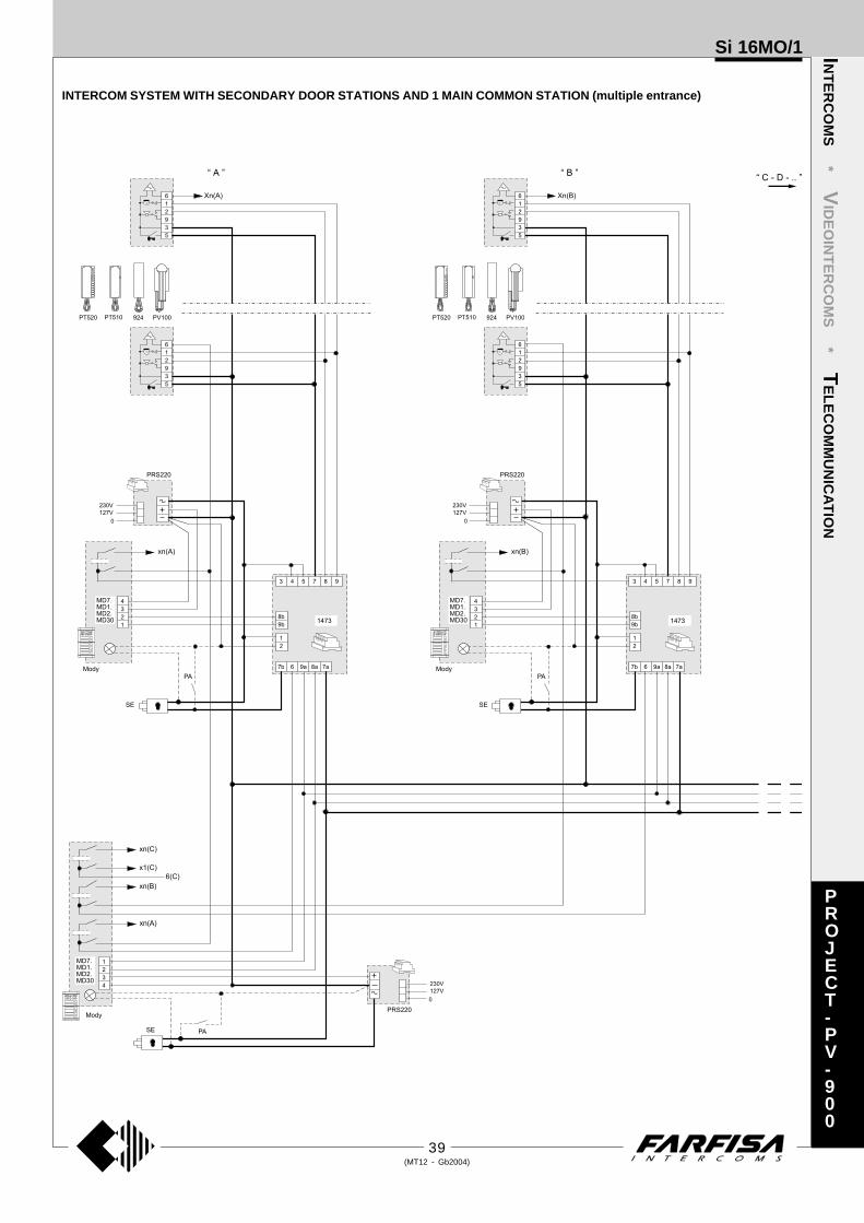
39(MT12 - Gb2004)
Si 16MO/1
INTERCOM SYSTEM WITH SECONDARY DOOR STATIONS AND 1 MAIN COMMON STATION (multiple entrance)
INT
ER
CO
MS
* VID
EO
INT
ER
CO
MS
* TE
LE
CO
MM
UN
ICA
TIO
N
PROJECT-PV-900

40(MT12 - Gb2004)
Si 16MO/2INT
ER
CO
MS
* VID
EO
INT
ER
CO
MS
* TE
LE
CO
MM
UN
ICA
TIO
N
ONE-WAY INTERCOM SYSTEM WITH SECONDARY DOOR STATIONS AND 1 MAIN COMMON STATION (multiple entrance)
PROJECT-PV-900
PA
SE
230V
127V
0
3 4 5 7 8 9
PRS210
1473
MD100
RP100
UP11
UP100
2
1
8b
9b
7b 6 9a 8a 7a
C
P
2
1
Q.ty Article Description
... PT 510 * Project series intercom with 1 call button1+X PRS220 Power supplyX 1473 Exchanger1+X PA ** Door release push-button (optional)1+X SE ** Electric door lock (12VAC-1A)
Door station series Mody (for items selection refer to pages 12÷15)
Secondary door stationsX MD71 Module frames with back boxX MD11 Module for electric door speakerX MD81 Hood coverX MD91 (2) Rain shelter with module framesX MD30 Electric door speaker (amplifier)
Main entrance1 row 2 row
... MD71÷74 MD71÷74 Module frames with back box1 MD10-11-12 MD10-122-124 Modules for electric door speaker... MD21 ÷ 24 MD222 ÷ 228 Button modules... MD20 - 50 MD20 - 50 Blank and info modules1 MD82 ÷ 812 MD82 ÷ 812 Hood covers1 MD92 ÷ 912 (2) MD92 ÷ 912 (2) Rain shelters with module frames1 MD30 MD30 Electric door speaker (amplifier)
Door station series Matrix (for items selection refer to pages 20 and 21)
Secondary door stationsX MA71 Module frames with back boxX MA11P Module with integrated audio amplifierX MA61 Front frame
Main entrance... MA71÷73 Module frames with back box1 MA10P-11P-12P Modules with integrated audio amplifier... MA20-22-24 Blank and button modules1 MA61 ÷ 63 Front frames
... Refers to number of users.X Refers to the number of stairways.* Besides the mentioned model all the intercoms from the Project,
PuntoVirgola, 900 and 700 can be installed.** Articles not supplied by ACI Farfisa.(2) Rain shelters are used instead of back boxes and hood covers.
Working instructions.As the basic system described on page 27, with the following variations:- The audio functions and door lock opening are automatically switched to the
door station which has made the call and remain in this state until a call fromanother entrance is received.
- Services to secondary door stations are independent and can be operated atthe same time.
Notes- For the connection of name-plate lamps, read notes 6, 7 and 8 of the
installation instructions on page 26.- For wires dimensioning refer to the installation recommendations and table
on page 26.- Telephones can be used instead of intercoms (see “telecommunication”
section).- For other types of push-button panels see pages 22 and 23 or the general
catalogue.
Application diagramWhen using MD100, RP100, UP11 and UP100 amplifiedexternal door stations as one-way secondary door stations,place this diagram on the diagram on page 41 and line it upwith the riser.
Warning.- Bridging of C and terminals is not necessary in
RP100 amplified external door stations.- For alternate current wires refer to note 6 of the installation
instructions on page 26.
Application of Matrix push-button panel
The button common terminal ofevery module CANNOT beseparated. For the composition ofthe push-button panel at the mainentrance, carefully select the buttonmodules in order to obtain thenecessary number of buttons forevery common terminal.

41(MT12 - Gb2004)
Si 16MO/2
ONE-WAY INTERCOM SYSTEM WITH SECONDARY DOOR STATIONS AND 1 MAIN COMMON STATION (multiple entrance)
INT
ER
CO
MS
* VID
EO
INT
ER
CO
MS
* TE
LE
CO
MM
UN
ICA
TIO
N
PROJECT-PV-900

42(MT12 - Gb2004)
Si 17MO/1INT
ER
CO
MS
* VID
EO
INT
ER
CO
MS
* TE
LE
CO
MM
UN
ICA
TIO
N
INTERCOM SYSTEM WITH SECONDARY DOOR STATIONS AND 2 MAIN COMMON STATIONS (multiple entrance)
common of buttons 1 and 2
to separate common of but-tons cut here
common of buttons 3 and 4
The main entrance push-button panel must haveseparate common terminals. One common terminalfor each secondary door station. Buttons of the Modyseries can be divided into 2-button groups.P
ROJECT-PV-900
Q.ty Article Description
... PT 510 * Project series intercom with 1 call button2+X PRS220 Power supply2xX 1473 Exchanger2+X PA ** Door release push-button (optional)2+X SE ** Electric door lock (12VAC-1A)
Door station series Mody (for items selection refer to pages 12÷15)
1 row 2 row... MD71÷74 MD71÷74 Module frames with back box2+X MD10-11-12 MD10-122-124 Modules for electric door speaker... MD21 ÷ 24 MD222 ÷ 228 Button modules... MD20 - 50 MD20 - 50 Blank and info modules2+X MD82 ÷ 812 MD82 ÷ 812 Hood covers2+X MD92 ÷ 912 (2) MD92 ÷ 912 (2) Rain shelters with module frames2+X MD30 MD30 Electric door speaker (amplifier)
Door station series Matrix (for items selection refer to pages 20 and 21)
... MA71÷73 Module frames with back box2+X MA10P-11P-12P Modules with integrated audio amplifier... MA20-22-24 Blank and button modules... MA61÷63 Front frames
... Refers to number of users.X Refers to the number of stairways.* Besides the mentioned model all the intercoms from the Project, PuntoVirgola, 900 and 700 can be
installed.** Articles not supplied by ACI Farfisa.(2) Rain shelters are used instead of back boxes and hood covers.
Working instructions.As the basic system described on page 27, with the following variations:- The audio functions and door lock opening are automatically switched to the door station which has
made the call and remain in this state until a call from another entrance is received.- Services to secondary door stations are independent and can be operated at the same time.
Notes- You can also use Prestige and TM push-button panels. For the latter series you must request the version
with separate common terminals.- For the connection of name-plate lamps, read notes 6, 7 and 8 of the installation instructions on page
26.- For wires dimensioning refer to the installation recommendations and table on page 26.- Telephones can be used instead of intercoms (see “telecommunication” section).- For other types of push-button panels see pages 22 and 23 or the general catalogue.
Floor callThis work diagram allows for differ-entiating the floor-call from the callfrom the push-button panel.
Application of Matrix push-button panel
The button common terminal ofevery module CANNOT beseparated. For the composition ofthe push-button panel at the mainentrance, carefully select the buttonmodules in order to obtain thenecessary number of buttons forevery common terminal.
Use the power supplywith electronicbuzzer PRS240instead of PRS220

43(MT12 - Gb2004)
Si 17MO/1
INTERCOM SYSTEM WITH SECONDARY DOOR STATIONS AND 2 MAIN COMMON STATIONS (multiple entrance)
INT
ER
CO
MS
* VID
EO
INT
ER
CO
MS
* TE
LE
CO
MM
UN
ICA
TIO
N
PROJECT-PV-900

44(MT12 - Gb2004)
Table for choosing intercoms and accessories for the required type of installation
Number of Project
intercommunicating PT520 PT501 PT524
2 2 0 2
3 3 0
4 4 4
5 5 10
6 6 18
7 7 28
8 8 40
9 9 54
10 10 70
11 11 88
Si 100L/2INT
ER
CO
MS
* VID
EO
INT
ER
CO
MS
* TE
LE
CO
MM
UN
ICA
TIO
N
2 INTERCOMMUNICATING INTERCOMS
Q.ty Article Description
2 PT524 * Project series intercom with 1 call button1 PRS220 Power supply
* Besides the mentioned model the intercom PT520 and PT520W can be installed..Working instructions.See page 27.
Notes- In each intercom to cut the jumper (W1) that links terminals 3 and 7.- In intercoms CT1 move the buzzer mobile connection from terminal 3 to 7.- In intercoms CT2 move the buzzer mobile connection from terminal 3 to 2 and connect
terminals 2 and 7 together.- For wires dimensioning refer to the installation recommendations and table on page 26.
INTERCOMMUNICATING INTERCOMS (2 to 11 users)
Q.ty Article Description
... PT520W Project series modular intercom
... PT501 Single button unit1 PRS231 Power supply
... Refers to number of users (see table).
Working instructions.See page 27.
Notes- In each intercom to cut the jumper (W1) that links terminals 3 and 7.- In each intercom to move the connection of the buzzer from terminal 3 to 2.- In all intercoms connect one of the two terminals of the single button unit to terminal 7.- For wires dimensioning refer to the installation recommendations and table on page 26.
PROJECT
PT 520
PT 524
PT 520
PT 524CT 1 CT 2
6 2 9 1 3 5 7
W1 W1
6 2 9 1 3 5 7
W1
1
PT 520
Si 100L/11

45(MT12 - Gb2004)
Si 100L/11
2 INTERCOMMUNICATING INTERCOMS
INT
ER
CO
MS
* VID
EO
INT
ER
CO
MS
* TE
LE
CO
MM
UN
ICA
TIO
N
PROJECT
CT
1C
T2
23
0V
12
7V 0
PR
S220
11
22
99
33
66
77
55
PT
52
0P
T5
24
INTERCOMMUNICATING INTERCOMS (2 to 11 users)
Si 100L/2

46(MT12 - Gb2004)
Si 115L/5SINT
ER
CO
MS
* VID
EO
INT
ER
CO
MS
* TE
LE
CO
MM
UN
ICA
TIO
N
5 INTERCOMMUNICATING INTERCOMS CONNECTED TO 1 EXTERNAL DOOR STATION WITH SINGLE CALLS. ELECTRONIC BELLFOR INTERNAL CALLS.
Q.ty Article Description
... PT520 Project series modular intercom
... PT501 Single button unit
... SR40 Electronic bell module1 PRS226 Power supply-switcher1 PA ** Door release push-button (optional)1 SE ** Electric door lock (12VAC-1A)
Door station series Mody (for right item set see on pages 12÷15)
1 row 2 row... MD71÷73 MD71÷73 Module frames with back box1 MD10-11-12 MD10-122-124 Modules for electric door speaker... MD21 ÷ 24 MD222 ÷ 228 Button modules... MD20 - 50 MD20 - 50 Blank and info modules1 MD81 ÷ 83 MD81 ÷ 83 Hood covers1 MD91 ÷ 93* MD91 ÷ 93* Rain shelters with module frames1 MD30 MD30 Electric door speaker (amplifier)
Door station series Matrix (for right item set see on pages 20 and 21)
... MA71÷73 Module frames with back box1 MA10P-11P-12P Modules with integrated audio amplifier... MA20-22-24 Blank and button modules... MA61÷63 Front frames
... Refers to number of users (see table).* Rain shelters are used instead of back boxes and hood
covers.** Articles not supplied by ACI Farfisa.
Working instructions. See page 27.
Notes- For the connection of name-plate lamps, read notes 6 and
7 of the installation instructions on page 26.- For wires dimensioning refer to the installation recommen-
dations and table on page 26.- For other types of push-button panels see pages 22 and 23
or the general catalogue.
PROJECT
Number of inter- Project Application dia-
communicating PT520 PT501 SR40/SR41 gram on page:
2 2 0 2 62 64
3 3 3 3 62 64
4 4 8 4 62 64
5 5 15 5 63 47
6 6 24 6 63 65
7 7 35 7 * 65
8 8 48 8 *
9 9 63 9 *
10 10 80 10 *
* upon request
Application diagramWhen using MD100, MD200, RP200, UP12 and UP200 amplifiedexternal door stations (RP and UP series for two-way systems only)place this diagram on the diagram on page 47 and line it up with theriser.
Warning.- In the external door stations RP200 cut the jumper W1.- In the external door stations UP do not connect the yellow wire and
insulate it.- For alternate current wires refer to note 6 of the installation instruc-
tions on page 26.
Table for choosing intercoms and accessories for the required type ofinstallation
In intercoms cut the jumper W1 that connectsterminals 3 and 7 and apply:- the electronic buzzer SR40 by connecting wires 7and 9 to the intercom terminals 3 and 9,
- or use the buzzer SR41 by connecting terminals 3of buzzer and intercom together and by connectingthe call wires to terminal 4 (instead of terminal as shown in the diagrams).
In all intercoms connect oneof the two terminals of the sin-gle button unit to terminal 7.

47(MT12 - Gb2004)
Si 115L/5S
5 INTERCOMMUNICATING INTERCOMS CONNECTED TO 1 EXTERNAL DOOR STATION WITH SINGLE CALLS. ELECTRONIC BELLFOR INTERNAL CALLS
INT
ER
CO
MS
* VID
EO
INT
ER
CO
MS
* TE
LE
CO
MM
UN
ICA
TIO
N
PROJECT

48(MT12 - Gb2004)
Si 111L/5MINT
ER
CO
MS
* VID
EO
INT
ER
CO
MS
* TE
LE
CO
MM
UN
ICA
TIO
N
5 INTERCOMMUNICATING INTERCOMS CONNECTED TO 1 EXTERNAL DOOR STATION WITH COMMON CALL. ELECTRONICBELL FOR INTERNAL CALLS.
Q.ty Article Description
... PT520 Project series modular intercom
... PT501 Single button unit
... SR40 Electronic bell module1 PRS226 Power supply-switcher1 PA ** Door release push-button (optional)1 SE ** Electric door lock (12VAC-1A)
Door station series Mody
1 MD71 Module frames with back box1 MD11 Module for electric door speaker1 MD81 Hood cover1 MD91* Rain shelter with module frames1 MD30 Electric door speaker (amplifier)
Door station series Matrix
1 MA71 Module frames with back box1 MA11P Module with integrated audio amplifier1 MA61 Front frame
... Refers to number of users (see table).* Rain shelters are used instead of back boxes and hood
covers.** Articles not supplied by ACI Farfisa.
Working instructions. See page 27.
Notes- For the connection of name-plate lamps, read notes 6 and
7 of the installation instructions on page 26.- For wires dimensioning refer to the installation recommen-
dations and table on page 26.- For other types of push-button panels see pages 22 and 23
or the general catalogue.
Application diagramWhen using MD100, MD200, RP200, UP12 and UP200 amplifiedexternal door stations (RP and UP series for two-way systems only)place this diagram on the diagram on page 49 and line it up with theriser.
Warning.- In the external door stations RP200 cut the jumper W1.- In the external door stations UP do not connect the yellow wire and
insulate it.- For alternate current wires refer to note 6 of the installation instruc-
tions on page 26.
PROJECT
In intercoms cut the jumper W1 that connectsterminals 3 and 7 and apply:- the electronic buzzer SR40 by connecting wires 7and 9 to the intercom terminals 3 and 9,
- or use the buzzer SR41 by connecting terminals 3of buzzer and intercom together and by connectingthe call wires to terminal 4 (instead of terminal as shown in the diagrams).
In all intercoms connect oneof the two terminals of the sin-gle button unit to terminal 7.
Number of inter- Project Application dia-
communicating PT520 PT501 SR40/SR41 gram on page:
2 2 0 2 66
3 3 3 3 66
4 4 8 4 66
5 5 15 5 49
6 6 24 6 67
7 7 35 7 67
8 8 48 8 *
9 9 63 9 *
10 10 80 10 *
* upon request
Table for choosing intercoms and accessories for the required type ofinstallation

49(MT12 - Gb2004)
Si 111L/5M
5 INTERCOMMUNICATING INTERCOMS CONNECTED TO 1 EXTERNAL DOOR STATION WITH COMMON CALL. ELECTRONICBELL FOR INTERNAL CALLS
INT
ER
CO
MS
* VID
EO
INT
ER
CO
MS
* TE
LE
CO
MM
UN
ICA
TIO
N
PA
SE
MD71
MD11
MD30
1
2
3
4
CT1 CT2 CT3 CT4 CT5
230V
127V
0
G 2 7
C+ D A
PRS226
PT520+
PT501+
SR40
PT520+
PT501+
SR40
PT520+
PT501+
SR40
PT520+
PT501+
SR40
PT520+
PT501+
SR40
2
3
4
1
2
9
3
6
5
7
P1
P2
P3
P4
1
2
9
3
6
5
7
P1
P2
P3
P4
1
2
9
3
6
5
7
P1
P2
P3
P4
1
2
9
3
6
5
7
P1
P2
P3
P4
1
2
9
3
6
5
7
P1
P2
P3
P4
1
SR40
MA71
MA11P
MA61
1
2
3
4
C
Mody Matrix
A
P
PROJECT

50(MT12 - Gb2004)
Si 125L/5SINT
ER
CO
MS
* VID
EO
INT
ER
CO
MS
* TE
LE
CO
MM
UN
ICA
TIO
N
5 INTERCOMMUNICATING INTERCOMS CONNECTED TO 2 EXTERNAL DOOR STATIONS WITH SINGLE CALLS. ELECTRONICBELL FOR INTERNAL CALLS.
Q.ty Article Description
... PT520 Project series modular intercom
... PT501 Single button unit
... SR40 Electronic bell module1 PRS226 Power supply-switcher1 1473 Exchanger2 PA ** Door release push-button (optional)2 SE ** Electric door lock (12VAC-1A)
Door station series Mody (for right item set see on pages 12÷15)
1 row 2 row... MD71÷73 MD71÷73 Module frames with back box2 MD10-11-12 MD10-122-124 Modules for electric door speaker... MD21 ÷ 24 MD222 ÷ 228 Button modules... MD20 - 50 MD20 - 50 Blank and info modules2 MD81 ÷ 83 MD81 ÷ 83 Hood covers2 MD91 ÷ 93* MD91 ÷ 93* Rain shelters with module frames2 MD30 MD30 Electric door speaker (amplifier)
Door station series Matrix (for right item set see on pages 20 and 21)
... MA71÷73 Module frames with back box2 MA10P-11P-12P Modules with integrated audio amplifier... MA20-22-24 Blank and button modules... MA61÷63 Front frames
... Refers to number of users (see table).* Rain shelters are used instead of back boxes and
hood covers.** Articles not supplied by ACI Farfisa.
Working instructionsAs the basic system described on page 27, with thefollowing variations:- The audio functions and door lock opening are auto-
matically switched to the door station which has madethe call and remain in this state until a call from anotherentrance is received.
Notes- For the connection of name-plate lamps, read notes 6
and 7 of the installation instructions on page 26.- For wires dimensioning refer to the installation recom-
mendations and table on page 26.- For other types of push-button panels see pages 22 and
23 or the general catalogue.
PROJECT
In intercoms cut the jumper W1 that connectsterminals 3 and 7 and apply:- the electronic buzzer SR40 by connecting wires 7and 9 to the intercom terminals 3 and 9,
- or use the buzzer SR41 by connecting terminals 3of buzzer and intercom together and by connectingthe call wires to terminal 4 (instead of terminal as shown in the diagrams).
In all intercoms connect oneof the two terminals of the sin-gle button unit to terminal 7.
Number of inter- Project Application dia-
communicating PT520 PT501 SR40/SR41 gram on page:
2 2 0 2 62 64
3 3 3 3 62 64
4 4 8 4 62 64
5 5 15 5 63 51
6 6 24 6 63 65
7 7 35 7 * 65
8 8 48 8 *
9 9 63 9 *
10 10 80 10 *
* upon request
Table for choosing intercoms and accessories for the required type ofinstallation

51(MT12 - Gb2004)
Si 125L/5S
5 INTERCOMMUNICATING INTERCOMS CONNECTED TO 2 EXTERNAL DOOR STATIONS WITH SINGLE CALLS. ELECTRONICBELL FOR INTERNAL CALLS
INT
ER
CO
MS
* VID
EO
INT
ER
CO
MS
* TE
LE
CO
MM
UN
ICA
TIO
N
PROJECT

52(MT12 - Gb2004)
Si 121L/5MINT
ER
CO
MS
* VID
EO
INT
ER
CO
MS
* TE
LE
CO
MM
UN
ICA
TIO
N
5 INTERCOMMUNICATING INTERCOMS CONNECTED TO 2 EXTERNAL DOOR STATIONS WITH COMMON CALL. ELECTRONICBELL FOR INTERNAL CALLS.
Q.ty Article Description
... PT520 Project series modular intercom
... PT501 Single button unit
... SR40 Electronic bell module1 PRS226 Power supply-switcher1 1473 Exchanger2 PA ** Door release push-button (optional)2 SE ** Electric door lock (12VAC-1A)
Door station series Mody
2 MD71 Module frames with back box2 MD11 Module for electric door speaker2 MD81 Hood cover2 MD91* Rain shelter with module frames2 MD30 Electric door speaker (amplifier)
Door station series Matrix
2 MA71 Module frames with back box2 MA11P Module with integrated audio amplifier2 MA61 Front frame
... Refers to number of users (see table).* Rain shelters are used instead of back boxes and hood
covers.** Articles not supplied by ACI Farfisa.
Working instructionsAs the basic system described on page 27, with thefollowing variations:- The audio functions and door lock opening are automati-
cally switched to the door station which has made the calland remain in this state until a call from another entranceis received.
Notes- For the connection of name-plate lamps, read notes 6
and 7 of the installation instructions on page 26.- For wires dimensioning refer to the installation recom-
mendations and table on page 26.- For other types of push-button panels see pages 22 and
23 or the general catalogue.
PROJECT
In intercoms cut the jumper W1 that connectsterminals 3 and 7 and apply:- the electronic buzzer SR40 by connecting wires 7and 9 to the intercom terminals 3 and 9,
- or use the buzzer SR41 by connecting terminals 3of buzzer and intercom together and by connectingthe call wires to terminal 4 (instead of terminal as shown in the diagrams).
In all intercoms connect oneof the two terminals of the sin-gle button unit to terminal 7.
Number of inter- Project Application dia-
communicating PT520 PT501 SR40/SR41 gram on page:
2 2 0 2 66
3 3 3 3 66
4 4 8 4 66
5 5 15 5 53
6 6 24 6 67
7 7 35 7 67
8 8 48 8 *
9 9 63 9 *
10 10 80 10 *
* upon request
Table for choosing intercoms and accessories for the required type ofinstallation

53(MT12 - Gb2004)
Si 121L/5M
5 INTERCOMMUNICATING INTERCOMS CONNECTED TO 2 EXTERNAL DOOR STATIONS WITH COMMON CALL. ELECTRONICBELL FOR INTERNAL CALLS
INT
ER
CO
MS
* VID
EO
INT
ER
CO
MS
* TE
LE
CO
MM
UN
ICA
TIO
N
PROJECT

54(MT12 - Gb2004)
Si 135L/5SINT
ER
CO
MS
* VID
EO
INT
ER
CO
MS
* TE
LE
CO
MM
UN
ICA
TIO
N
5 INTERCOMMUNICATING INTERCOMS CONNECTED TO 3 EXTERNAL DOOR STATIONS WITH SINGLE CALLS. ELECTRONICBELL FOR INTERNAL CALLS.
Q.ty Article Description
... PT520 Project series modular intercom
... PT501 Single button unit
... SR40 Electronic bell module1 PRS226 Power supply-switcher2 1473 Exchanger3 PA ** Door release push-button (optional)3 SE ** Electric door lock (12VAC-1A)
Door station series Mody (for right item set see on pages 12÷15)
1 row 2 row... MD71÷73 MD71÷73 Module frames with back box3 MD10-11-12 MD10-122-124 Modules for electric door speaker... MD21 ÷ 24 MD222 ÷ 228 Button modules... MD20 - 50 MD20 - 50 Blank and info modules3 MD81 ÷ 83 MD81 ÷ 83 Hood covers3 MD91 ÷ 93* MD91 ÷ 93* Rain shelters with module frames3 MD30 MD30 Electric door speaker (amplifier)
Door station series Matrix (for right item set see on pages 20 and 21)
... MA71÷73 Module frames with back box3 MA10P-11P-12P Modules with integrated audio amplifier... MA20-22-24 Blank and button modules... MA61÷63 Front frames
... Refers to number of users (see table).* Rain shelters are used instead of back boxes and
hood covers.** Articles not supplied by ACI Farfisa.
Working instructionsAs the basic system described on page 27, with thefollowing variations:- The audio functions and door lock opening are auto-
matically switched to the door station which has madethe call and remain in this state until a call from anotherentrance is received.
Notes- For the connection of name-plate lamps, read notes 6
and 7 of the installation instructions on page 26.- For wires dimensioning refer to the installation recom-
mendations and table on page 26.- For other types of push-button panels see pages 22 and
23 or the general catalogue.
PROJECT
In intercoms cut the jumper W1 that connectsterminals 3 and 7 and apply:- the electronic buzzer SR40 by connecting wires 7and 9 to the intercom terminals 3 and 9,
- or use the buzzer SR41 by connecting terminals 3of buzzer and intercom together and by connectingthe call wires to terminal 4 (instead of terminal as shown in the diagrams).
In all intercoms connect oneof the two terminals of the sin-gle button unit to terminal 7.
Number of inter- Project Application dia-
communicating PT520 PT501 SR40/SR41 gram on page:
2 2 0 2 62 64
3 3 3 3 62 64
4 4 8 4 62 64
5 5 15 5 63 55
6 6 24 6 63 65
7 7 35 7 * 65
8 8 48 8 *
9 9 63 9 *
10 10 80 10 *
* upon request
Table for choosing intercoms and accessories for the required type ofinstallation

55(MT12 - Gb2004)
Si 135L/5S
5 INTERCOMMUNICATING INTERCOMS CONNECTED TO 3 EXTERNAL DOOR STATIONS WITH SINGLE CALLS. ELECTRONICBELL FOR INTERNAL CALLS
INT
ER
CO
MS
* VID
EO
INT
ER
CO
MS
* TE
LE
CO
MM
UN
ICA
TIO
N
PROJECT

56(MT12 - Gb2004)
Si 131L/5MINT
ER
CO
MS
* VID
EO
INT
ER
CO
MS
* TE
LE
CO
MM
UN
ICA
TIO
N
5 INTERCOMMUNICATING INTERCOMS CONNECTED TO 3 EXTERNAL DOOR STATIONS WITH COMMON CALL. ELECTRONICBELL FOR INTERNAL CALLS.
Q.ty Article Description
... PT520 Project series modular intercom
... PT501 Single button unit
... SR40 Electronic bell module1 PRS226 Power supply-switcher2 1473 Exchanger3 PA ** Door release push-button (optional)3 SE ** Electric door lock (12VAC-1A)
Door station series Mody
3 MD71 Module frames with back box3 MD11 Module for electric door speaker3 MD81 Hood cover3 MD91* Rain shelter with module frames3 MD30 Electric door speaker (amplifier)
Door station series Matrix
3 MA71 Module frames with back box3 MA11P Module with integrated audio amplifier3 MA61 Front frame
... Refers to number of users (see table).* Rain shelters are used instead of back boxes and hood
covers.** Articles not supplied by ACI Farfisa.
Working instructionsAs the basic system described on page 27, with thefollowing variations:- The audio functions and door lock opening are automati-
cally switched to the door station which has made the calland remain in this state until a call from another entranceis received.
Notes- For the connection of name-plate lamps, read notes 6
and 7 of the installation instructions on page 26.- For wires dimensioning refer to the installation recom-
mendations and table on page 26.- For other types of push-button panels see pages 22 and
23 or the general catalogue.
PROJECT
In intercoms cut the jumper W1 that connectsterminals 3 and 7 and apply:- the electronic buzzer SR40 by connecting wires 7and 9 to the intercom terminals 3 and 9,
- or use the buzzer SR41 by connecting terminals 3of buzzer and intercom together and by connectingthe call wires to terminal 4 (instead of terminal as shown in the diagrams).
In all intercoms connect oneof the two terminals of the sin-gle button unit to terminal 7.
Number of inter- Project Application dia-
communicating PT520 PT501 SR40/SR41 gram on page:
2 2 0 2 66
3 3 3 3 66
4 4 8 4 66
5 5 15 5 57
6 6 24 6 67
7 7 35 7 67
8 8 48 8 *
9 9 63 9 *
10 10 80 10 *
* upon request
Table for choosing intercoms and accessories for the required type ofinstallation
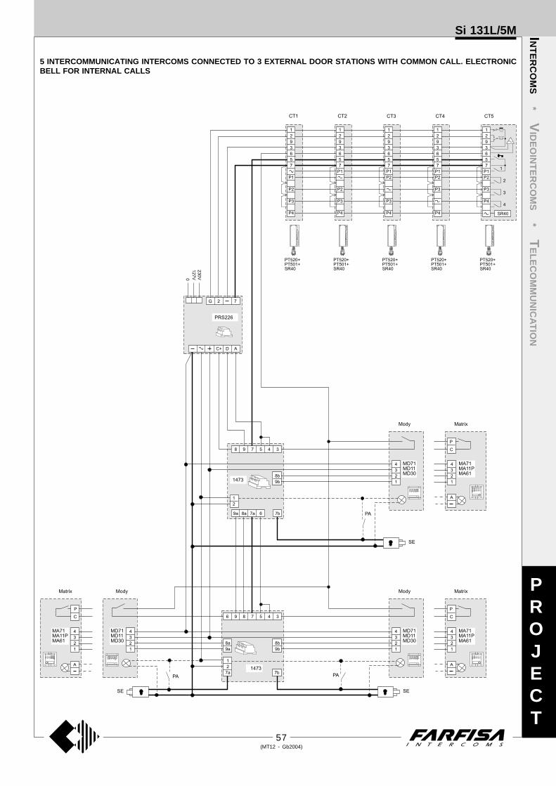
57(MT12 - Gb2004)
Si 131L/5M
5 INTERCOMMUNICATING INTERCOMS CONNECTED TO 3 EXTERNAL DOOR STATIONS WITH COMMON CALL. ELECTRONICBELL FOR INTERNAL CALLS
INT
ER
CO
MS
* VID
EO
INT
ER
CO
MS
* TE
LE
CO
MM
UN
ICA
TIO
N
PROJECT

58(MT12 - Gb2004)
Si 161L/1INT
ER
CO
MS
* VID
EO
INT
ER
CO
MS
* TE
LE
CO
MM
UN
ICA
TIO
N
ONE-WAY INTERCOMMUNICATING SYSTEM WITH SECONDARY DOOR STATIONS AND 1 MAIN COMMON STATION (multipleentrance).
Q.ty Article Description
... PT520 Project series modular intercom
... PT501 Single button unit1 PRS220 Power supplyX PRS226E Power supply-switcherX 1473 Exchanger1+X PA ** Door release push-button (optional)1+X SE ** Electric door lock (12VAC-1A)
Door station series Mody (for right item set see on pages 12÷15)
Secondary door stationsX MD71 Module frames with back boxX MD11 Module for electric door speakerX MD81 Hood coverX MD91* Rain shelter with module framesX MD30 Electric door speaker (amplifier)
Main entrance1 row 2 row
... MD71÷74 MD71÷74 Module frames with back box1 MD10-11-12 MD10-122-124 Modules for electric door speaker... MD21 ÷ 24 MD222 ÷ 228 Button modules... MD20 - 50 MD20 - 50 Blank and info modules1 MD82 ÷ 812 MD82 ÷ 812 Hood covers1 MD92 ÷ 912* MD92 ÷ 912* Rain shelters with module frames1 MD30 MD30 Electric door speaker (amplifier)
Door station series Matrix (for right item set see on pages 20 and 21)
Secondary door stationsX MA71 Module frames with back boxX MA11P Module with integrated audio amplifierX MA61 Front frame
Main entrance... MA71÷73 Module frames with back box1 MA10P-11P-12P Modules with integrated audio amplifier... MA20-22-24 Blank and button modules... MA61÷63 Front frames
PROJECT
- In every intercommunicating intercom ap-ply the single button group by connecting oneof the two button terminals to terminal 7 ofthe power supply PRS226E.
- Do not use button no. 1 for intercommuni-cating calls.
... Refers to number of users.X Refers to the number of stairways.* Rain shelters are used instead of back boxes and hood covers.** Articles not supplied by ACI Farfisa.
Working instructions.As the basic system described on page 27, with the following variations:- The audio functions and door lock opening are automatically switched to the door
station which has made the call and remain in this state until a call from anotherentrance is received.
- Services to secondary door stations are independent and can be operated at thesame time.
Notes- For the connection of name-plate lamps, read notes 6 and 7 of the installation
instructions on page 26.- For wires dimensioning refer to the installation recommendations and table on page
26.- For other types of push-button panels see pages 22 and 23 or the general catalogue.
Number of inter- Project
communicating PT520 PT501
2 2 0
3 3 3
4 4 8
5 5 15
6 6 24
7 7 35
8 8 48
9 9 63
10 10 80
Table for choosing intercoms and accessoriesfor the required type of installation

59(MT12 - Gb2004)
Si 161L/1
ONE-WAY INTERCOMMUNICATING SYSTEM WITH SECONDARY DOOR STATIONS AND 1 MAIN COMMON STATION (multipleentrance)
INT
ER
CO
MS
* VID
EO
INT
ER
CO
MS
* TE
LE
CO
MM
UN
ICA
TIO
N
PROJECT

60(MT12 - Gb2004)
Si 11MO/3INT
ER
CO
MS
* VID
EO
INT
ER
CO
MS
* TE
LE
CO
MM
UN
ICA
TIO
N
MULTI-WAY INTERCOM SYSTEM CONNECTED TO 1 EXTERNAL DOOR STATION. With intercommunication service in 1 or moreapartments and private conversation feature with the external door station and the other apartments.
Q.ty Article Description
... PT 510 * Project series intercom with 1 call button1 PRS220 Power supply1 PA ** Door release push-button (optional)1 SE ** Electric door lock (12VAC-1A)
Door station series Mody (for right item set see on pages 12÷15)
1 row 2 row... MD71÷74 MD71÷74 Module frames with back box1 MD10-11-12 MD10-122-124 Modules for electric door speaker... MD21 ÷ 24 MD222 ÷ 228 Button modules... MD20 - 50 MD20 - 50 Blank and info modules1 MD82 ÷ 812 MD82 ÷ 812 Hood covers1 MD92 ÷ 912 (2) MD92 ÷ 912 (2) Rain shelters with module frames1 MD30 MD30 Electric door speaker (amplifier)
Door station series Matrix (for right item set see on pages 20 and 21)
... MA71÷73 Module frames with back box1 MA10P-11P-12P Modules with integrated audio amplifier... MA20-22-24 Blank and button modules... MA61÷63 Front frames
Articles required for every intercommunicating flat
... PT520 Intercom with 2 call buttons
... PT501 Single button unit1 PRS226E Power supply-switcher
... Refers to number of users.* Besides the mentioned model all the intercoms from the Project, PuntoVirgola, 900 and 700 can be installed.** Articles not supplied by ACI Farfisa.(2) Rain shelters are used instead of back boxes and hood covers.
Working instructions. See page 27.
Notes
PROJECT-PV-900
- In every intercommunicating intercom ap-ply the single button group by connecting oneof the two button terminals to terminal 7 ofthe power supply PRS226E.
- Do not use button no. 1 for intercommuni-cating calls.
- To use MD100 and MD200 amplified external door sta-tions, combine the diagram on page 61 to the diagram onpage 30 by aligning it to the riser.
- For the connection of name-plate lamps, read notes 6, 7 and 8of the installation instructions on page 26.
- For wires dimensioning refer to the installation recommenda-tions and table on page 26.
- Telephones can be used instead of intercoms (see “telecom-munication” section).
- For other types of push-button panels see pages 22 and 23 orthe general catalogue.
Number of inter- Project Application dia-
communicating PT520 PT501 gram on page:
2 2 0 68
3 3 3 68
4 4 8 69
5 5 15 69
6 6 24 70
7 7 35 70
8 8 48 upon request
9 9 63 upon request
10 10 80 upon request
Table for choosing intercoms and accessories for the required typeof installation

61(MT12 - Gb2004)
Si 11MO/3
MULTI-WAY INTERCOM SYSTEM CONNECTED TO 1 EXTERNAL DOOR STATION. With intercommunication service in 1 or moreapartments and private conversation feature with the external door station and the other apartments.
INT
ER
CO
MS
* VID
EO
INT
ER
CO
MS
* TE
LE
CO
MM
UN
ICA
TIO
N
PROJECT-PV-900

62(MT12 - Gb2004)
Application diagrams
2 INTERCOMMUNICATING INTERCOMS
INT
ER
CO
MS
* VID
EO
INT
ER
CO
MS
* TE
LE
CO
MM
UN
ICA
TIO
N
3 INTERCOMMUNICATING INTERCOMS
4 INTERCOMMUNICATING INTERCOMS
ADDITIONAL DIAGRAMS FOR INTERCOMMUNICATING SYSTEMS WITH SINGLE EXTERNAL CALL. BOTH CALLS ACTIVATE THEBUZZER.
- To match with diagrams: Si 115L/5S; Si 125L/5S; Si 135L/5S
to power supply to power supply
to power supply
PROJECT
In all intercoms connect one of thetwo terminals of the single buttonunit to terminal 7.
In all intercoms connect one of the twoterminals of the single button unit to ter-minal 7.
In each intercom to cut the jumper (W1) thatlinks terminals 3 and 7.
W1
1
PT 520
In each intercom to cut the jumper (W1)that links terminals 3 and 7
W1
1
PT 520
In each intercom to cut the jumper (W1)that links terminals 3 and 7
W1
1
PT 520
multi-way intercommunicating services

63(MT12 - Gb2004)
CT1 CT2 CT3 CT4 CT5 CT6
2
3
4
5
1
2
9
3
5
7
P1
6
P2
P3
P4
P5
1
2
9
3
5
7
P1
P2
P3
6
P4
P5
1
2
9
3
5
7
P1
P2
6
P3
P4
P5
1
2
9
3
5
7
P1
P2
P3
P4
6
P5
7
P1
P2
P3
P4
P5
6
1
2
9
3
5
x2
x3
x4
x5
xn
1
2
9
3
5
7
6
P1
P2
P3
P4
P5
PT520+
PT501
PT520+
PT501
PT520+
PT501
PT520+
PT501
PT520+
PT501
PT520+
PT501
1
5 INTERCOMMUNICATING INTERCOMS
INT
ER
CO
MS
* VID
EO
INT
ER
CO
MS
* TE
LE
CO
MM
UN
ICA
TIO
N
6 INTERCOMMUNICATING INTERCOMS
Application diagrams
to power supply
to power supply
PROJECT
In each intercom to cut the jumper(W1) that links terminals 3 and 7
W1
1
PT 520
In all intercoms connect one of the twoterminals of the single button unit to termi-nal 7.
In each intercom to cut the jumper(W1) that links terminals 3 and 7
W1
1
PT 520
In all intercoms connect one of the twoterminals of the single button unit to termi-nal 7.
multi-way intercommunicating services

64(MT12 - Gb2004)
Application diagramsINT
ER
CO
MS
* VID
EO
INT
ER
CO
MS
* TE
LE
CO
MM
UN
ICA
TIO
N
APPLICATION DIAGRAMS FOR INTERCOMMUNICATING SYSTEMS WITH SINGLE ALTERNATE CURRENT CALL FROM EXTER-NAL STATION AND ELECTRONIC CALL FOR EXTENSIONS
- To match with diagrams: Si 115L/5S; Si 125L/5S; Si 135L/5S
multi-way intercommunicating services
3 INTERCOMMUNICATING INTERCOMS
4 INTERCOMMUNICATING INTERCOMS
2 INTERCOMMUNICATING INTERCOMS
to power supply to power supply
to power supply
In intercoms cut the jumper W1 which connects terminals 3 and 7and apply the electronic buzzer SR40 or SR41 (for the application seethe drawings on the page that illustrates the electrical diagram to berealised).
In intercoms cut the jumper W1 which connects terminals 3 and 7and apply the electronic buzzer SR40 or SR41 (for the application seethe drawings on the page that illustrates the electrical diagram to berealised).
In intercoms cut the jumper W1 which connects terminals 3 and 7and apply the electronic buzzer SR40 or SR41 (for the application seethe drawings on the page that illustrates the electrical diagram to berealised).
PROJECT

65(MT12 - Gb2004)
6 INTERCOMMUNICATING INTERCOMS
INT
ER
CO
MS
* VID
EO
INT
ER
CO
MS
* TE
LE
CO
MM
UN
ICA
TIO
N
7 INTERCOMMUNICATING INTERCOMS
Application diagrams
to power supply
to power supply
PROJECT
multi-way intercommunicating services
In intercoms cut the jumper W1 which connects terminals 3 and 7and apply the electronic buzzer SR40 or SR41 (for the application seethe drawings on the page that illustrates the electrical diagram to berealised).
In intercoms cut the jumper W1 which connects terminals 3 and 7and apply the electronic buzzer SR40 or SR41 (for the application seethe drawings on the page that illustrates the electrical diagram to berealised).

66(MT12 - Gb2004)
CT1 CT2 CT3
1
2
9
3
6
5
7
P1
P2
P3
1
2
9
3
6
5
7
P1
P2
P3
1
2
9
3
6
5
7
P1
P2
P3
CT4
2
3
7
P1
P2
P3
1
2
9
3
6
5
PT520+
PT501+
SR40
PT520+
PT501+
SR40
PT520+
PT501+
SR40
PT520+
PT501+
SR40
SR40
1
CT1 CT2 CT3
1
2
9
3
6
5
7
P1
P2
1
2
9
3
6
5
7
P1
P2
2
7
P1
P2
1
2
9
3
6
5
PT520+
PT501+
SR40
PT520+
PT501+
SR40
PT520+
PT501+
SR40
SR40
1
CT1 CT2
1
2
9
3
6
5
7
P1
7
P1
1
2
9
3
6
5
PT520+
SR40
PT520+
SR40
1
SR40
INT
ER
CO
MS
* VID
EO
INT
ER
CO
MS
* TE
LE
CO
MM
UN
ICA
TIO
N
Application diagrams
3 INTERCOMMUNICATING INTERCOMS
4 INTERCOMMUNICATING INTERCOMS
2 INTERCOMMUNICATING INTERCOMS
APPLICATION DIAGRAMS FOR INTERCOMMUNICATING SYSTEMS WITH COMMON ALTERNATE CURRENT CALL FROM EXTER-NAL STATION AND ELECTRONIC CALL FOR EXTENSIONS- To match with diagrams: Si 111L/5M; Si 121L/5M; Si 131L/5M
to power supply to power supply
to power supply
PROJECT
one-way intercommunicating services
In intercoms cut the jumper W1 which connects terminals 3 and 7and apply the electronic buzzer SR40 or SR41 (for the application seethe drawings on the page that illustrates the electrical diagram to berealised).
In intercoms cut the jumper W1 which connects terminals 3 and 7and apply the electronic buzzer SR40 or SR41 (for the application seethe drawings on the page that illustrates the electrical diagram to berealised).
In intercoms cut the jumper W1 which connects terminals 3 and 7and apply the electronic buzzer SR40 or SR41 (for the application seethe drawings on the page that illustrates the electrical diagram to berealised).

67(MT12 - Gb2004)
CT1 CT2 CT3 CT4 CT5
1
2
9
3
6
5
7
P1
P2
P3
P4
P5
1
2
9
3
6
5
7
P1
P2
P3
P4
P5
1
2
9
3
6
5
7
P1
P2
P3
P4
P5
1
2
9
3
6
5
7
P1
P2
P3
P4
P5
1
2
9
3
6
5
7
P1
P2
P3
P4
P5
CT6
2
3
4
5
7
P1
P2
P3
P4
P5
1
2
9
3
6
5
PT520+
PT501+
SR40
PT520+
PT501+
SR40
PT520+
PT501+
SR40
PT520+
PT501+
SR40
PT520+
PT501+
SR40
PT520+
PT501+
SR40
230V
127V
0
1471 PRS210
1 6
5
3
SR40
1
CT1 CT2 CT3 CT4 CT5 CT6
1
2
9
3
6
5
7
P1
P2
P3
P4
P5
P6
1
2
9
3
6
5
7
P1
P2
P3
P4
P5
P6
1
2
9
3
6
5
7
P1
P2
P3
P4
P5
P6
1
2
9
3
6
5
7
P1
P2
P3
P4
P5
P6
1
2
9
3
6
5
7
P1
P2
P3
P4
P5
P6
1
2
9
3
6
5
7
P1
P2
P3
P4
P5
P6
CT7
2
3
4
5
6
7
P1
P2
P3
P4
P5
P6
1
2
9
3
6
5
PT520+
PT501+
SR40
PT520+
PT501+
SR40
PT520+
PT501+
SR40
PT520+
PT501+
SR40
PT520+
PT501+
SR40
PT520+
PT501+
SR40
PT520+
PT501+
SR40
230V
127V
0
1471 PRS210
1 6
5
3
SR40
1
INT
ER
CO
MS
* VID
EO
INT
ER
CO
MS
* TE
LE
CO
MM
UN
ICA
TIO
N
6 INTERCOMMUNICATING INTERCOMS
7 INTERCOMMUNICATING INTERCOMS
Application diagrams
to power supply
to power supply
PROJECT
one-way intercommunicating services
In intercoms cut the jumper W1 which connects terminals 3 and 7and apply the electronic buzzer SR40 or SR41 (for the application seethe drawings on the page that illustrates the electrical diagram to berealised).
In intercoms cut the jumper W1 which connects terminals 3 and 7and apply the electronic buzzer SR40 or SR41 (for the application seethe drawings on the page that illustrates the electrical diagram to berealised).

68(MT12 - Gb2004)
INT
ER
CO
MS
* VID
EO
INT
ER
CO
MS
* TE
LE
CO
MM
UN
ICA
TIO
N
Application diagrams
APPLICATION DIAGRAMS FOR ONE-WAY INTERCOMMUNICATING SERVICES IN APARTMENT BUILDING SYSTEMS. ALTERNATECURRENT CALL FROM THE DOOR STATION AND ELECTRONIC FOR EXTENSIONS- To match with diagrams: Si11MO/1; Si11MO/2; Si12MO/1; Si13MO/1; Si16MO/1; Si17MO/1 (example of application on page 61- Si11MO/3).
2 INTERCOMMUNICATING INTERCOMS
to riser
to riser
PROJECT
one-way intercommunicating services in apartment building system
3 INTERCOMMUNICATING INTERCOMS
- In every intercommunicating intercom ap-ply the single button group by connecting oneof the two button terminals to terminal 7 ofthe power supply PRS226E.
- Do not use button no. 1 for intercommuni-cating calls.
- In every intercommunicating intercom ap-ply the single button group by connecting oneof the two button terminals to terminal 7 ofthe power supply PRS226E.
- Do not use button no. 1 for intercommuni-cating calls.

69(MT12 - Gb2004)
INT
ER
CO
MS
* VID
EO
INT
ER
CO
MS
* TE
LE
CO
MM
UN
ICA
TIO
N
PROJECT
5 INTERCOMMUNICATING INTERCOMS
4 INTERCOMMUNICATING INTERCOMS
to riser
Application diagrams one-way intercommunicating services in apartment building system
to riser
- In every intercommunicating intercom ap-ply the single button group by connecting oneof the two button terminals to terminal 7 ofthe power supply PRS226E.
- Do not use button no. 1 for intercommuni-cating calls.
- In every intercommunicating intercom ap-ply the single button group by connecting oneof the two button terminals to terminal 7 ofthe power supply PRS226E.
- Do not use button no. 1 for intercommuni-cating calls.

70(MT12 - Gb2004)
Application diagramsINT
ER
CO
MS
* VID
EO
INT
ER
CO
MS
* TE
LE
CO
MM
UN
ICA
TIO
N
PROJECT
7 INTERCOMMUNICATING INTERCOMS
6 INTERCOMMUNICATING INTERCOMS
to riser
to riser
one-way intercommunicating services in apartment building system
- In every intercommunicating intercom ap-ply the single button group by connecting oneof the two button terminals to terminal 7 ofthe power supply PRS226E.
- Do not use button no. 1 for intercommuni-cating calls.
- In every intercommunicating intercom ap-ply the single button group by connecting oneof the two button terminals to terminal 7 ofthe power supply PRS226E.
- Do not use button no. 1 for intercommuni-cating calls.

71(MT12 - Gb2004)
INT
ER
CO
MS
* VID
EO
INT
ER
CO
MS
* TE
LE
CO
MM
UN
ICA
TIO
N
VIDEOINTERCOMSTechnical manual 12 Edition 2004
INDEX
Internal stations
- Project series videointercoms
- PuntoVirgola series videointercoms
External door stations
- Mody series push-button panels
- Matrix series push-button panels
Power supply and control units
Service modules
Installation instructions
Working instructions
Troubleshooting
Installation diagrams
- Si 311O/1 One-way video intercom connection with multi-core cable art.1304
- Si 311O/14 One-way video intercom system with long distance between video intercom and main power supply
- Si 31MO/1 Video intercom system connected to one external door station
- Si 31MC/1 Mixed intercom and video intercom system connected to one external door station
- Si 31MO/2 Video intercom system connected to one external door station with surveillance camera
- Si 32MO/1 Video intercom system connected to two external door stations
- Si 32MO/2 Video intercom system connected to two external door stations, one of which only audio
- Si 33MO/1 Video intercom system connected to three external door stations
- Si 33MO/2 Video intercom system connected to three external door stations, one of which only audio
- Si 33MO/7 Video intercom system connected to three external door stations, two of which only audio
- Si 36MO/2 Video intercom system with secondary video stations and 1 main common video station (multiple entrance)
- Si 36MO/3 Video intercom system with secondary door stations only audio and 1 main common video station (multiple entrance)
- Si 36MO/4 Video intercom system with secondary video stations and 1 main common station only audio (multiple entrance)
- Si 36MO/5 Video intercom system with one-way secondary door stations only audio and 1 main common video station (multiple
entrance)
- Si 37MO/1 Video intercom system with secondary video stations and 2 main common video stations (multiple entrance)
Additional diagrams
- One-way
- Multi-way
Page
72
72
78
81
81
86
90
90
91
94
94
95
96
97
99
101
103
105
107
109
111
113
115
117
119
121
123
124
126
137

72(MT12 - Gb2004)
INT
ER
CO
MS
* VID
EO
INT
ER
CO
MS
* TE
LE
CO
MM
UN
ICA
TIO
N
Videointercoms Project series
INTERNAL STATIONS
PT5160. Two-colour flat tube videointercom withaudio-video privacy, electronic microphone, differ-entiated double electronic ringing sounds (modu-lated and continuous note) and terminal board forthe connection to the wall-bracket. With two but-tons, one for control switch ON and one for door lockrelease, and 6 supplementary buttons, that can beadded for additional services such as: control switchON, intercommunicating calls, stair lights, door lockrelease, etc. The buttons are included in the kit ofthe videointercom. The maximum acceptable cur-rent to the button terminals is 60mA. For highercurrents use relay unit art.1471. It can be installedon the wall (with no built-in) by using the wall-bracketWB5100 or WB5160. For particular needs it ispossible to separate the common of the buttonslabelled P4, P5 and P6 by cutting the W1 jumper onthe wall-bracket. The buttons have the 2C terminalin common. In this case the maximum acceptablecurrent to the three buttons is 0.5A.
PT5160W. This model has the same features asthe previous one, but with a white finish.
Technical dataPower Supply 18÷24VdcOperating current 0.35AVideo tube 4" FLAT CRTTelevision standard 625 linesHorizontal frequency 15625HzVertical frequency 50HzBandwidth >5MHzVideo signal on 75Ω 0.8÷1.5VppStarting up time 2÷4 sec.Operating temperature 0°÷+50°CMax. permissible humidity 90%RH
PT5160W-LCD. Version with colour LCD screenvideointercom PT5160W.
Note: This version is applied to all video installa-tion diagrams with coaxial cable.
Technical dataPower Supply 18÷24VdcOperating current 0.4AScreen 4" LCDTelevision standard PALHorizontal frequency 15625HzVertical frequency 50HzBandwidth >5MHzVideo signal on 75Ω 0.8÷1.5VppStarting up time 1 sec.Operating temperature 0°÷+50°CMax. permissible humidity 90%RH
Inserting of extra buttons.
Measures for the installation of the wall bracketWB5100 or WB5160 to the wall, and recom-mended height from the floor.
Taking out of button caps.
Supplementary push-buttons installation
WB5100. The wall bracket includes aterminal board for connection to the sys-tem, it is to be used when installing 2 -button videointercoms (control switch-ON and door lock release), with a onecall.
Terminals1 Video signal input 0.8÷1.5Vpp2 General ground3 Video ground4 Control switch ON - button 8 Positive power supply output for video
floor distributors 12Vdc9 Door lock release - button 10 Call from the door station (180mA)11 Audio ground12 Microphone output13 Speaker and automatic cancel14 Positive power supply input 18÷24VdcV Not connected
WB5160. The wall bracket includes 2 terminalboards for connection to the system, it is to beused when installing videointercoms with extrabuttons and/or 2 differentiated bells.Located on the wall-bracket terminal board is aJ1 jumper positioned for the intercommunicat-ing service (position A).By using the PT5160, PT5160W andPT5160W-LCD videointercoms with multi-waysystems without the intercommunicating serv-ice, the audio privacy can be restored by posi-tioning the jumper J1 in B.
TerminalsThe terminals from 1 to 14 have the same func-tions and characteristics as the previous model.
V Activation input for digital systemsX1 AC power supply input 13Vac-0.35AX2 Intercommunicating call input (ground com-
mand)1C Common for P1, P2 and P3 buttons2C Common for P4, P5 and P6 buttonsP1÷P6 Service buttons - max 60mA
Wall-brackets for the PT5160, PT5160W and PT5160W-LCD videointercoms.
PROJECT
215.5
8 "2/1
89
3 "2/1
215
8 "16/
7
aaaaaaaaaaaa
U
P
U
P
140 150 cm÷
1 "/5
1
3
4
"
"
"
16
16
16
/
/
/
43
83.5
122
11
5
13
40.5
4" 7" 4" 11"÷

73(MT12 - Gb2004)
INT
ER
CO
MS
* VID
EO
INT
ER
CO
MS
* TE
LE
CO
MM
UN
ICA
TIO
N
Videointercoms Project series
INTERNAL STATIONS
TA5160. Table adapter for videointercomsPT5160, PT5160W and PT5160W-LCD.With 20 wires connection cable, junction boxand bracket with 2 terminals board.
TerminalsThe terminals have the same numbers, functionsand characteristics as those of wall bracketWB5160.
Mounting instructionMake the connection of the cable tothe terminals of the table adapter.Make the connection of the conduc-tors of the system to the junction box.Plug-in the 2 flat cable to the tableadapter.Fasten the videointercom to the tableadapter.
X1 X2 2C 1C P1 P2 P3 P4 P5 P6
2 4 8 9 10 11 12 13 14 V
1
1 2 3
J1
W175
J1
J1
1 2 3
1 2 3
A
B
3
1 Position for the intercommuni-cating service.
Position for the audio privacy.
WB 5160TA 5160
U
P
U
P
Installation of the wall bracket WB5100 orWB5160 to the wall, using a 83.5mm backbox and one expansion plugs.
Dismounting of videointercom from thewall bracket.
Audio privacy or intercommunicating service
Installation of videointercom tothe table adapter.
Installation of videointercom onto thewall bracket.
Plugging in of videointercom connectors to the termi-nal boards of wall bracket.
U
P
U
P
J2
J3
U
P
U
P
Installation of the wall bracket WB5100 orWB5160 to the wall, by means of expansionplugs.
Junction box.
PROJECT

74(MT12 - Gb2004)
INT
ER
CO
MS
* VID
EO
INT
ER
CO
MS
* TE
LE
CO
MM
UN
ICA
TIO
N
INTERNAL STATIONS
PT5660W. White colour videointercom withtraditional cathode tube with audio-video pri-vacy, electronic microphone, differentiateddouble electronic ringing sounds (modulatedand continuous note) and terminal board for theconnection to the wall-bracket. With two but-tons, one for control switch ON and one for doorlock release, and 6 supplementary buttons, thatcan be added for additional services such as:control switch ON, intercommunicating calls,stair lights, door lock release, etc. The buttonsare included in the kit of the videointercom. Themaximum acceptable current to the button ter-minals is 60mA. For higher currents use relayunit art.1471.It can be installed on the wall by using the wall-bracket art.WB5600 or WB5660 and the back-box art. 1283. For particular needs it is possi-ble to separate the common of the buttonslabelled P4, P5 and P6 by cutting the W1jumper on the wall-bracket. The buttons havethe 2C terminal in common. In this case themaximum acceptable current to the three but-tons is 0.5A.
Technical dataPower Supply 18÷24VdcOperating current 0.6AVideo tube 4.5" - 90°Television standard 625 linesHorizontal frequency 15625HzVertical frequency 50HzBandwidth >5MHzVideo signal on 75Ω 0.8÷1.5VppStarting up time 5÷7 sec.Operating temperature 0°÷+50°CMax. permissible humidity 90%RH
Videointercoms Project series
Installation of wall bracket WB5600 or WB5660 to the back box 1283.
U
P
Plugging in of videointercom connectors to the terminal boards of wall bracket.
Wall-brackets for the PT5660W videointercoms.
WB5600. The wall bracket includes aterminal board for connection to the sys-tem, it is to be used when installing 2 -button videointercoms (control switch-ON and door lock release), with a onecall.
Terminals1 Video signal input 0.8÷1.5Vpp2 General ground3 Video ground4 Control switch ON - button 8 Positive power supply output for video
floor distributors 12Vdc9 Door lock release - button 10 Call from the door station (180mA)11 Audio ground12 Microphone output13 Speaker and automatic cancel14 Positive power supply input 18÷24VdcV Not connected
WB5660. The wall bracket includes 2 terminalboards for connection to the system, it is to beused when installing videointercoms with extrabuttons and/or 2 differentiated bells.Located on the wall-bracket terminal board is aJ1 jumper positioned for the intercommunicat-ing service (position A).By using the PT5660W videointercoms withmulti-way systems without the intercommuni-cating service, the audio privacy can be re-stored by positioning the jumper J1 in B.
TerminalsThe terminals from 1 to 14 have the same func-tions and characteristics as the previous model.
V Activation input for digital systemsX1 AC power supply input 13Vac-0.35AX2 Intercommunicating call input (ground com-
mand)1C Common for P1, P2 and P3 buttons2C Common for P4, P5 and P6 buttonsP1÷P6 Service buttons - max 60mA
U
P
U
P
J3
J2
PROJECT
233
9 "16/
3
212 54
8 2" "2 8/ /
1 1
113
4 "16/
7
65
21
43

75(MT12 - Gb2004)
INT
ER
CO
MS
* VID
EO
INT
ER
CO
MS
* TE
LE
CO
MM
UN
ICA
TIO
N
Videointercoms Project series
INTERNAL STATIONS
Position for the intercommu-nicating service.
Position for the audio privacy.
J3
W1
J1
1 2 3 J1
J1
1 2 3
1 2 3
A
B
2 X1
4 X2
8 2C
9 1C
10 P1
11 P2
12 P3
13 P4
14 P5
V P6
R1
75
1 1
3
J2
WB 5660
Audio privacy or intercommunicating service
Inserting of extra buttons.
1283. Back-box for videointercoms PT5660Wand PV1260.Place the box on the wall at a height of about1.5m (4' 11") from the floor keeping the frontedges flush-mounted and vertical to the fin-ished plaster.
Supplementary push-buttons installation
Taking out of button caps.
Installation of videointercom onto the wall bracket.
Dismounting of videointercom from the wallbracket.
PROJECT
11"
aaaaaaaaaaaaaaaaaaaaaaaaaaaaaaaaaaaaaaaa
2 "8/3
60
4
16/15
126
6 "8/7
175
140 150 cm÷
4 "
4 7"

76(MT12 - Gb2004)
INT
ER
CO
MS
* VID
EO
INT
ER
CO
MS
* TE
LE
CO
MM
UN
ICA
TIO
N
INTERNAL STATIONS
PT5860. Two-colour reflex videointercom withaudio-video privacy, electronic microphone,differentiated double electronic ringing sounds(modulated and continuous note) and terminalboard for the connection to the wall-bracket.With two buttons, one for control switch ON andone for door lock release, and 6 supplementarybuttons, that can be added for additional serv-ices such as: control switch ON, intercommuni-cating calls, stair lights, door lock release, etc.The buttons are included in the kit of thevideointercom. The maximum acceptable cur-rent to the button terminals is 60mA. For highercurrents use relay unit art.1471.It can be installed on the wall by using the wall-bracket art.WB5600 or WB5660. For particu-lar needs it is possible to separate the commonof the buttons labeled P4, P5 and P6 by cuttingthe W1 jumper on the wall-bracket. The buttonshave the 2C terminal in common. In this casethe maximum acceptable current to the threebuttons is 0.5A.
PT5860W. This model has the same featuresas the previous one, but with a white finish.
Technical dataPower Supply 18÷24VdcOperating current 0.6AVideo tube 4.5" - 90°Television standard 625 linesHorizontal frequency 15625HzVertical frequency 50HzBandwidth >5MHzVideo signal on 75Ω 0.8÷1.5VppStarting up time 5÷7 sec.Operating temperature 0°÷+50°CMax. permissible humidity 90%RH
Videointercoms Project series
Measures for the installation of the wall bracket WB5600or WB5660 to the wall, and recommended height fromthe floor.
UPUP
Installation of the wall bracket WB5600 or WB5660 to thewall, by means of expansion plugs.
Wall-brackets for the PT5860 and PT5860W videointercoms.
WB5660. The wall bracket includes 2 terminalboards for connection to the system, it is to beused when installing videointercoms with extrabuttons and/or 2 differentiated bells.Located on the wall-bracket terminal board is aJ1 jumper positioned for the intercommunicat-ing service (position A).By using the PT5860 and PT5860W video-intercoms with multi-way systems without theintercommunicating service, the audio privacycan be restored by positioning the jumper J1 inB.
TerminalsThe terminals from 1 to 14 have the same func-tions and characteristics as the previous model.
V Activation input for digital systemsX1 AC power supply input 13Vac-0.35AX2 Intercommunicating call input (ground com-
mand)1C Common for P1, P2 and P3 buttons2C Common for P4, P5 and P6 buttonsP1÷P6 Service buttons - max 60mA
WB5600. The wall bracket includes aterminal board for connection to the sys-tem, it is to be used when installing 2 -button videointercoms (control switch-ON and door lock release), with a onecall.
Terminals1 Video signal input 0.8÷1.5Vpp2 General ground3 Video ground4 Control switch ON - button 8 Positive power supply output for video
floor distributors 12Vdc9 Door lock release - button 10 Call from the door station (180mA)11 Audio ground12 Microphone output13 Speaker and automatic cancel14 Positive power supply input 18÷24VdcV Not connected
PROJECT
233
9 "16/
3
212
8 "2/
1
113
4 "16/
7
65
21
43
UPUP
aaaaaaaaaaaaaaaaaaaaaaaaaaaaaa
138
140 150 cm÷
3
5
"
"
8
16
/
/
925
7
4" 7" 4" 11"÷

77(MT12 - Gb2004)
INT
ER
CO
MS
* VID
EO
INT
ER
CO
MS
* TE
LE
CO
MM
UN
ICA
TIO
N
Videointercoms Project series
INTERNAL STATIONS
Position for the intercommu-nicating service.
Position for the audio privacy.
J3
W1
J1
1 2 3 J1
J1
1 2 3
1 2 3
A
B
2 X1
4 X2
8 2C
9 1C
10 P1
11 P2
12 P3
13 P4
14 P5
V P6
R1
75
1 1
3
J2
WB 5660
Audio privacy or intercommunicating service
Inserting of extra buttons.
Supplementary push-buttons installation
Taking out of button caps.
Plugging in of videointercom connectors to the terminal boards of wallbracket.
Dismounting of videointercom from the wallbracket.
Installation of videointercom onto thewall bracket.
U
P
U
P
J3
J2
PROJECT

78(MT12 - Gb2004)
INT
ER
CO
MS
* VID
EO
INT
ER
CO
MS
* TE
LE
CO
MM
UN
ICA
TIO
N
Videointercoms PuntoVirgola series
INTERNAL STATIONS
PV2160. Two-colour flat tube videointercomwith audio-video privacy, electronic micro-phone, differentiated double electronic ringingsounds (modulated and continuous note) andterminal board for the connection to the wall-bracket. With two buttons, one for control switchON and one for door lock release, and 5 sup-plementary buttons, that can be added for ad-ditional services such as: control switch ON,intercommunicating calls, stair lights, door lockrelease, etc. The buttons are included in the kitof the videointercom. The maximum accept-able current to the button terminals is 60mA.For higher currents use relay unit art.1471. Itcan be installed on the wall (with no built-in) byusing the wall-bracket WB2100 or WB2160.For particular needs it is possible to separatethe common of the buttons labeled T4 and T5by cutting the W1 jumper on the wall-bracket.The buttons have the 2C terminal in common. Inthis case the maximum acceptable current tothe three buttons is 0.5A.
PV2160W. This model has the same featuresas the previous one, but with a white finish.
Technical dataPower Supply 18÷24VdcOperating current 0.35AVideo tube 4" FLAT CRTTelevision standard 625 linesHorizontal frequency 15625HzVertical frequency 50HzBandwidth >5MHzVideo signal on 75Ω 0.8÷1.5VppStarting up time 2÷4 sec.Operating temperature 0°÷+50°CMax. permissible humidity 90%RH
Measures for the installation of the wall bracket WB2100 orWB2160 to the wall, and recommended height from thefloor.
Installation of the wall bracket WB2100 or WB2160 to the wall, by means ofexpansion plugs.
Wall-brackets for the PV2160 and PV2160W videointercoms.
WB2100. The wall bracket includes aterminal board for connection to the sys-tem, it is to be used when installing 2 -button videointercoms (control switch-ON and door lock release), with a onecall.
Terminals1 Video signal input 0.8÷1.5Vpp2 General ground3 Video ground4 Control switch ON - button 8 Positive power supply output for video
floor distributors 12Vdc9 Door lock release - button 10 Call from the door station (180mA)11 Audio ground12 Microphone output13 Speaker and automatic cancel14 Positive power supply input 18÷24VdcV Not connected
WB2160. The wall bracket includes 2 terminalboards for connection to the system, it is to beused when installing videointercoms with extrabuttons and/or 2 differentiated bells.Located on the wall-bracket terminal board is aJ1 jumper positioned for the intercommunicat-ing service (position A).By using the PV2160 and PV2160W video-intercoms with multi-way systems without theintercommunicating service, the audio privacycan be restored by positioning the jumper J1 inB.
TerminalsThe terminals from 1 to 14 have the same func-tions and characteristics as the previous model.
V Activation input for digital systemsX1 AC power supply input 13Vac-0.35AX2 Intercommunicating call input (ground com-
mand)1C Common for T1, T2 and T3 buttons2C Common for T4 and T5 buttonsT1÷T5 Service buttons - max 60mAP1 Not connected
PUNTOVIRGOLA
7 "4/
1973
3 "
76
9 "
228
aaaaaaaaaaaa
U
P
U
P
140 150 cm÷
1 "/5
1
3
4
"
"
"
16
16
16
/
/
/
43
83.5
122
11
5
13
40.5
4" 7" 4" 11"÷

79(MT12 - Gb2004)
INT
ER
CO
MS
* VID
EO
INT
ER
CO
MS
* TE
LE
CO
MM
UN
ICA
TIO
N
Videointercoms PuntoVirgola series
Installation of videointercom onto the wall bracket.
U
P
J2 J3
Plugging in of videointercom connectors to the terminal boardsof wall bracket.
INTERNAL STATIONS
T5
T4
T3
T2
T1
1C
2C
X2
X1
P1
V
14
13
12
11
10
9
8
4
2
3
1 1R1
75
J1
3
2
1
J1
J1
1 2 3
1 2 3
A
B
WB2160
Position for the in-tercommunicatingservice.
Position for the au-dio privacy.
Audio privacy or intercommunicating service
Supplementary push-buttons installation
Taking out of button caps. Inserting of extra buttons.
PUNTOVIRGOLA
PV1260. Two-colour videointercom with tradi-tional cathode tube with audio-video privacy,electronic microphone, differentiated doubleelectronic ringing sounds (modulated and acontinuous note) and terminal board for theconnection to the wall-bracket. With 2 buttons,one for control switch ON and the other for doorlock release and 6 supplementary service but-tons that can be added for additional servicessuch as: control switch ON, intercommunicat-ing calls, stair lights, door lock release, etc. Thebuttons are included in the kit of the video-intercom. The maximum acceptable current tothe buttons is 60mA. For higher currents usethe art.1471 relay unit. It can be installed on thewall using the wall-bracket WB1200 orWB1260 and the back-box art.1283. For par-ticular needs it is possible to separate thecommon of the buttons labelled P4, P5 and P6by cutting the W1 jumper located on the con-necting terminal board. These buttons have incommon the C2 terminal. In this case the maxi-mum acceptable current to the buttons is 0.5A.
Technical dataPower Supply 18÷24VdcOperating current 0.6AVideo tube 4.5"-90°Television standard 625 linesHorizontal frequency 15625HzVertical frequency 50HzBand width >5MHzVideo signal on 75Ω 0.8÷1.5VppStarting up time 5÷7 sec.Operating temperature 0°÷+50°CMax. permissible humidity 90%RH
Videointercoms PuntoVirgolaseries
Installation of wall bracket WB1200 or WB1260 tothe back box 1283.
5 "8/7
149
8 "16/1
205
3 "16/
9
909 "
8/
2383
5 "2/1
140

80(MT12 - Gb2004)
INT
ER
CO
MS
* VID
EO
INT
ER
CO
MS
* TE
LE
CO
MM
UN
ICA
TIO
N
Videointercoms PuntoVirgola
INTERNAL STATIONS
Supplementary push-buttons installation
Inserting of extra buttons.
Taking out of button caps.
Wall-brackets for the PV1260 video-intercom.
WB1200. The wall bracket includes a terminalboard for connection to the system, it is to beused when installing 2 - button videointercoms(control switch-ON and door lock release), witha one call.
Terminals1 Video signal input 0.8÷1.5Vpp2 General ground3 Video ground4 Control switch ON - button8 Positive power supply output for video floor
distributors 12Vdc9 Door lock release - button10 Call from the door station (180mA)11 Audio ground12 Microphone output13 Speaker and automatic cancel14 Positive power supply input 18÷24Vdc-0.6AV Not connected
WB1260. The wall bracket includes 2 terminalboards for connection to the system, it is to beused when installing videointercoms with extrabuttons and/or 2 differentiated bells.Located on the wall-bracket terminal board is aJ1 jumper positioned for the intercommunicat-ing service (position A).By using the PV1260 videointercom with multi-way systems without the intercommunicatingservice, the audio privacy can be restored bypositioning the jumper J1 in B.
TerminalsThe terminals from 1 to 14 have the same func-tions and characteristics as the previous model.
V Activation input for digital systemsX1 AC power supply input 13Vac-0.35AX2 Intercommunicating call input (ground com-
mand)1C Common for P1, P2 and P3 buttons2C Common for P4, P5 and P6 buttonsP1÷P6 Service buttons - max 60mA
1283. Back-box for PV1260 and PT5660Wvideointercoms.Place the box on the wall at a height of about1.5m (4' 11") from the floor keeping the frontedges flush-mounted and vertical to the fin-ished plaster.
Plugging in of videointercomconnectors to the terminalboards of wall bracket.
Installation of videointercom onto the wallbracket.
WB1260
X1 X2 2C 1C P1 P2 P3 P4 P5 P6
2 4 8 9 10 11 12 13 14 V
1
1 2 3
J1
W175
J1
J1
1 2 3
1 2 3
A
B
3
1 Position for the intercommuni-cating service.
Position for the audio privacy.
Audio privacy or intercommunicating service
PUNTOVIRGOLA
11"
aaaaaaaaaaaaaaaaaaaaaaaaaaaaaaaaaaaaaaaa
2 "8/3
60
4
16/15
126
6 "8/7
175
140 150 cm÷
4 "
4 7"

81(MT12 - Gb2004)
INT
ER
CO
MS
* VID
EO
INT
ER
CO
MS
* TE
LE
CO
MM
UN
ICA
TIO
N
MODY
Place the push-button panel back box at aheight of about 1.65m (5' 5") from the floorkeeping the front edges flush-mounted andvertical to the finished plaster.Position the camera in such a way thatsunlight or other direct or reflected lightsources with high intensity do not hit thecamera lens.
PUSH-BUTTON PANELS
MD41.B/W adjustable camera complete with:- solid-state sensor (CCD), electronic autoiris,3.6mm fixed optics and 6 infrared LEDs;
- front plate of anodized aluminium with break-proof transparent screen;
- horizontal and vertical adjustment.
MD41C Color.Colour adjustable camera complete with:- solid-state sensor (CCD), autoiris and 4mmfixed optics;
- front plate of anodized aluminium with break-proof transparent screen;
- horizontal and vertical adjustment.
TerminalsV Video signal outputM GroundF Not connectedH Power supply input
H
F
M
V
EXTERNAL DOOR STATIONS
CAMERAS
Technical data MD41 MD41C
Power supply 21±3Vdc 21±3VdcOperating current 0.2A 0.4AVideo signal output 1Vpp on 75Ω 1Vpp on 75ΩVideo signal standard CCIR PALMinimum illumination 2 Lux 2.5 LuxWhite balance - autoSensor CCD 1/4" B/W CCD 1/3" colourNumber of pixels 291,000 291,000Horizontal frequency 15,625Hz 15,625HzVertical frequency 50Hz 50HzLens 3.6mm; F5 4mm; F4Focus 0.1m ÷ ∞ 0.6m ÷ ∞Autoiris electronic electronicHorizontal adjustment ± 15° ± 15°Vertical adjustment ± 15° ± 15°Operating temperature -10°÷+40°C -10°÷+40°CMax. permissible humidity 80%RH 80%RH
Installation
For information on characteristics and assem-bly of push-button panels, electric door speak-
ers, back boxes, rain shelters, hood covers andmodules see section “intercoms” on page 7 to
page 11.
AdjustmentsIf necessary, you can manually modify the cam-era position by means of the horizontal andvertical adjustments located on the back of thecamera.To do this, you must:- remove the upper screw of the push-button
panel to access the back of the camera;- loosen the screw of the horizontal or vertical
adjustment (or both screws, if you want toadjust the image in all the directions);
- move the camera in the desired direction;- tighten the screw to block the camera in the
desired position;- fix the push-button panel.
Horizontal (±15°)
Vertical (±15°)
NoteMD40 and MD40C cameras have the same specifications as models MD41 and MD41C,except that they have not horizontal and vertical adjustments.
aaaaaaaaaa
5 ' 5 "
"16/
14 "8/
7
52124
90
2
"16/9
"4/3
19
3

82(MT12 - Gb2004)
INT
ER
CO
MS
* VID
EO
INT
ER
CO
MS
* TE
LE
CO
MM
UN
ICA
TIO
N
43 call buttons
5 05 0
58 call buttons48 call buttons 52 call buttons
5 05 0
35 call buttons 40 call buttons37 call buttons
MODY seriespush-button panels
Examples of compositions of Mody push-button panels in video intercom systems
42 call buttons38 call buttons
27 call buttons
5 05 0
32 call buttons28 call buttons 30 call buttons 34 call buttons
5 05 0
16 call buttons
7 call buttons
5 05 0
11 call buttons
5 0
12 call buttons
1 call button 2 call buttons 3 call buttons 10 call buttons4 call buttons 5 call buttons 6 call buttons 7 call buttons 8 call buttons
8 call buttons 9 call buttons 10 call buttons 14 call buttons
26 call buttons24 call buttons23 call buttons21 call buttons
5 05 0
19 call buttons
5 05 0
18 call buttons
1 row push-buttonEXTERNAL DOOR STATIONS
MODY

83(MT12 - Gb2004)
INT
ER
CO
MS
* VID
EO
INT
ER
CO
MS
* TE
LE
CO
MM
UN
ICA
TIO
N
MODY series push-button panels Composition board of Mody push-button panels.Rain
shelterHood
coversBack box andmodule frame
Button and info orblank modules
Module forspeaker
Door speaker(amplifier)
Cameramodule
Compositions anddimensions
N°calls
1 MD41
1 MD41
1 MD41
1 MD41
1 MD41
1 MD41
1 MD41
1 MD41
1 MD41
1 MD41
1 MD41
1 MD41
1 MD41
1 MD41
1 MD41
1 MD41
1 MD41
1 MD41
1 MD41
1 MD41
1 MD41
1 MD41
1 MD41
1 MD41
1 MD41
1 MD41
1 MD41
1 MD41
1 MD41
1 MD41
1 MD41
1 MD41
1 MD41
1 MD41
1 MD41
1 MD41
1 MD41
1 MD41
1 MD41
1 MD41
1 MD41
1 MD41
1 MD41
1 MD41
1 MD41
1 MD41
1 MD41
1 MD41
1 MD41
1 MD41
1 MD41
1 MD30
1 MD30
1 MD30
1 MD30
1 MD30
1 MD30
1 MD30
1 MD30
1 MD30
1 MD30
1 MD30
1 MD30
1 MD30
1 MD30
1 MD30
1 MD30
1 MD30
1 MD30
1 MD30
1 MD30
1 MD30
1 MD30
1 MD30
1 MD30
1 MD30
1 MD30
1 MD30
1 MD30
1 MD30
1 MD30
1 MD30
1 MD30
1 MD30
1 MD30
1 MD30
1 MD30
1 MD30
1 MD30
1 MD30
1 MD30
1 MD30
1 MD30
1 MD30
1 MD30
1 MD30
1 MD30
1 MD30
1 MD30
1 MD30
1 MD30
1 MD30
1 MD11
1 MD12
1 MD10
1 MD10
1 MD11
1 MD12
1 MD10
1 MD10
1 MD11
1 MD12
1 MD10
1 MD10
1 MD11
1 MD12
1 MD10
1 MD10
1 MD11
1 MD12
1 MD10
1 MD10
1 MD11
1 MD12
1 MD12
1 MD12
1 MD12
1 MD12
1 MD11
1 MD10
1 MD11
1 MD12
1 MD11
1 MD12
1 MD11
1 MD12
1 MD12
1 MD12
1 MD11
1 MD12
1 MD11
1 MD12
1 MD12
1 MD12
1 MD12
1 MD11
1 MD10
1 MD11
1 MD10
1 MD12
1 MD10
1 MD12
1 MD12
-
-
1 MD23
1 MD24
1 MD24
1 MD24
1 MD24
2 MD24
2 MD24
2 MD24
2 MD24
3 MD24
3 MD24
3 MD24
3 MD24
4 MD24
4 MD24
4 MD24
4 MD24
5 MD24
5 MD24
5 MD24
5 MD24
5 MD24
5 MD24
6 MD24
5 MD24
7 MD24
7 MD24
7 MD24
6 MD24
6 MD24
8 MD24
8 MD24
8 MD24
8 MD24
8 MD24
8 MD24
8 MD24
8 MD24
9 MD24
10 MD24
8 MD24
11 MD24
11 MD24
11 MD24
11 MD24
11 MD24
11 MD24
11 MD24
14 MD24
1 MD72
1 MD72
1 MD73
1 MD73
1 MD73
1 MD73
2 MD72
2 MD72
2 MD72
2 MD72
2 MD73
2 MD73
2 MD73
2 MD73
2 MD73
2 MD73
2 MD73
2 MD73
2 MD74
2 MD74
2 MD74
2 MD74
2 MD74
2 MD74
2 MD74
2 MD74
3 MD73
3 MD73
3 MD73
3 MD73
3 MD74
3 MD74
3 MD74
3 MD74
3 MD74
3 MD74
3 MD74
3 MD74
3 MD74
3 MD74
3 MD74
3 MD74
4 MD74
4 MD74
4 MD74
4 MD74
4 MD74
4 MD74
4 MD74
4 MD74
4 MD74
1 MD82
1 MD82
1 MD83
1 MD83
1 MD83
1 MD83
1 MD84
1 MD84
1 MD84
1 MD84
1 MD86
1 MD86
1 MD86
1 MD86
1 MD86
1 MD86
1 MD86
1 MD86
1 MD808
1 MD808
1 MD808
1 MD808
1 MD808
1 MD808
1 MD808
1 MD808
1 MD89
1 MD89
1 MD89
1 MD89
1 MD812
1 MD812
1 MD812
1 MD812
1 MD812
1 MD812
1 MD812
1 MD812
1 MD812
1 MD812
1 MD812
1 MD812
-
-
-
-
-
-
-
-
-
1 MD92
1 MD92
1 MD93
1 MD93
1 MD93
1 MD93
1 MD94
1 MD94
1 MD94
1 MD94
1 MD96
1 MD96
1 MD96
1 MD96
1 MD96
1 MD96
1 MD96
1 MD96
1 MD908
1 MD908
1 MD908
1 MD908
1 MD908
1 MD908
1 MD908
1 MD908
1 MD99
1 MD99
1 MD99
1 MD99
1 MD912
1 MD912
1 MD912
1 MD912
1 MD912
1 MD912
1 MD912
1 MD912
1 MD912
1 MD912
1 MD912
1 MD912
-
-
-
-
-
-
-
-
-
* or MD20 or MD50 or FC52P or FP52 Optional It replacesMD72, 73, 74
or MD74 or MD804 or MD904
1 row push-button
1
2
3
4
5
6
7
8
9
10
11
12
13
14
15
16
17
18
19
20
21
22
23
24
25
26
27
28
29
30
31
32
33
34
35
36
37
38
39
40
41
42
43
45
47
48
50
52
53
55
58
-
-
-
-
-
-
1 MD23
-
-
-
1 MD23
-
-
-
1 MD23
-
-
-
1 MD23
-
-
-
1 MD21
1 MD22
1 MD23
-
2 MD23
-
-
-
2 MD23
2 MD23
-
-
1 MD21
2 MD21
2 MD22
2 MD22
2 MD23
2 MD23
1 MD23
-
3 MD23
-
3 MD21
3 MD21
3 MD22
3 MD22
3 MD23
3 MD23
-
-
-
-
-
-
-
-
-
-
-
1 *
1 *
1 *
1 *
-
-
-
-
1 *
1 *
1 *
1 *
-
-
-
-
-
-
-
-
2 *
2 *
2 *
2 *
1 *
-
-
-
-
-
-
-
3 *
3 *
-
-
-
-
-
-
-
EXTERNAL DOOR STATIONS
MODY
124x213x19(47/
8" x 8 3/
8" x 3/
4")
248x304.5x19(9 3/
4"
x 12" x
3/
4")
248x395x19(9 3/4" x 15 9/16" x 3/4")
496x395x19(19 1/2" x 15 9/16" x 3/4")
372x395x19(14 5/
8"
x 15 9/
16" x
3/
4")
124x304,5x19(47/
8" x 12" x 3/
4")
248x213x19(9 3/4" x 8 3/8" x
3/4")
372x304.5x19(14 5/8" x 12" x
3/4")

84(MT12 - Gb2004)
INT
ER
CO
MS
* VID
EO
INT
ER
CO
MS
* TE
LE
CO
MM
UN
ICA
TIO
N
86 call buttons
5 05 0
116 call buttons96 call buttons 104 call buttons
5 05 0
70 call buttons 80 call buttons74 call buttons
MODY seriespush-button panels
Examples of compositions of Mody push-button panels in video intercom systems
84 call buttons76 call buttons
54 call buttons
5 05 0
64 call buttons56 call buttons 60 call buttons 68 call buttons
5 05 0
32 call buttons
28 call buttons14 call buttons 20 call buttons16 call buttons 18 call buttons
5 05 0
22 call buttons 24 call buttons
2 call buttons 4 call buttons 6 call buttons 20 call buttons8 call buttons 10 call buttons 12 call buttons
52 call buttons48 call buttons46 call buttons
5 05 0
42 call buttons
5 05 0
38 call buttons36 call buttons
14 call buttons 16 call buttons
2 row push-buttonEXTERNAL DOOR STATIONS
MODY

85(MT12 - Gb2004)
INT
ER
CO
MS
* VID
EO
INT
ER
CO
MS
* TE
LE
CO
MM
UN
ICA
TIO
N
MODY series push-button panels Composition board of Mody push-button panels.Rain
shelterHood
coversBack box andmodule frame
Button and info orblank modules
Module forspeaker
Door speaker(amplifier)
Cameramodule
Compositions anddimensions
N°calls
2
4
6
8
10
12
14
16
18
20
22
24
26
28
30
32
34
36
38
40
42
44
46
48
50
52
54
56
58
60
62
64
66
68
70
72
74
76
78
80
82
84
86
90
94
96
100
104
106
110
116
1 MD41
1 MD41
1 MD41
1 MD41
1 MD41
1 MD41
1 MD41
1 MD41
1 MD41
1 MD41
1 MD41
1 MD41
1 MD41
1 MD41
1 MD41
1 MD41
1 MD41
1 MD41
1 MD41
1 MD41
1 MD41
1 MD41
1 MD41
1 MD41
1 MD41
1 MD41
1 MD41
1 MD41
1 MD41
1 MD41
1 MD41
1 MD41
1 MD41
1 MD41
1 MD41
1 MD41
1 MD41
1 MD41
1 MD41
1 MD41
1 MD41
1 MD41
1 MD41
1 MD41
1 MD41
1 MD41
1 MD41
1 MD41
1 MD41
1 MD41
1 MD41
1 MD30
1 MD30
1 MD30
1 MD30
1 MD30
1 MD30
1 MD30
1 MD30
1 MD30
1 MD30
1 MD30
1 MD30
1 MD30
1 MD30
1 MD30
1 MD30
1 MD30
1 MD30
1 MD30
1 MD30
1 MD30
1 MD30
1 MD30
1 MD30
1 MD30
1 MD30
1 MD30
1 MD30
1 MD30
1 MD30
1 MD30
1 MD30
1 MD30
1 MD30
1 MD30
1 MD30
1 MD30
1 MD30
1 MD30
1 MD30
1 MD30
1 MD30
1 MD30
1 MD30
1 MD30
1 MD30
1 MD30
1 MD30
1 MD30
1 MD30
1 MD30
1 MD122
1 MD124
1 MD10
1 MD10
1 MD122
1 MD124
1 MD10
1 MD10
1 MD122
1 MD124
1 MD10
1 MD10
1 MD122
1 MD124
1 MD10
1 MD10
1 MD122
1 MD124
1 MD10
1 MD10
1 MD122
1 MD124
1 MD124
1 MD124
1 MD124
1 MD124
1 MD122
1 MD124
1 MD122
1 MD124
1 MD122
1 MD124
1 MD122
1 MD124
1 MD124
1 MD124
1 MD122
1 MD124
1 MD122
1 MD124
1 MD124
1 MD124
1 MD124
1 MD122
1 MD10
1 MD122
1 MD10
1 MD124
1 MD10
1 MD124
1 MD124
-
-
1 MD226
1 MD228
1 MD228
1 MD228
1 MD228
2 MD228
2 MD228
2 MD228
2 MD228
3 MD228
3 MD228
3 MD228
3 MD228
4 MD228
4 MD228
4 MD228
4 MD228
5 MD228
5 MD228
5 MD228
5 MD228
5 MD228
5 MD228
6 MD228
5 MD228
7 MD228
7 MD228
7 MD228
6 MD228
6 MD228
8 MD228
8 MD228
8 MD228
8 MD228
8 MD228
8 MD228
8 MD228
8 MD228
9 MD228
10 MD228
8 MD228
11 MD228
11 MD228
11 MD228
11 MD228
11 MD228
11 MD228
11 MD228
14 MD228
1 MD72
1 MD72
1 MD73
1 MD73
1 MD73
1 MD73
2 MD72
2 MD72
2 MD72
2 MD72
2 MD73
2 MD73
2 MD73
2 MD73
2 MD73
2 MD73
2 MD73
2 MD73
2 MD74
2 MD74
2 MD74
2 MD74
2 MD74
2 MD74
2 MD74
2 MD74
3 MD73
3 MD73
3 MD73
3 MD73
3 MD74
3 MD74
3 MD74
3 MD74
3 MD74
3 MD74
3 MD74
3 MD74
3 MD74
3 MD74
3 MD74
3 MD74
4 MD74
4 MD74
4 MD74
4 MD74
4 MD74
4 MD74
4 MD74
4 MD74
4 MD74
1 MD82
1 MD82
1 MD83
1 MD83
1 MD83
1 MD83
1 MD84
1 MD84
1 MD84
1 MD84
1 MD86
1 MD86
1 MD86
1 MD86
1 MD86
1 MD86
1 MD86
1 MD86
1 MD808
1 MD808
1 MD808
1 MD808
1 MD808
1 MD808
1 MD808
1 MD808
1 MD89
1 MD89
1 MD89
1 MD89
1 MD812
1 MD812
1 MD812
1 MD812
1 MD812
1 MD812
1 MD812
1 MD812
1 MD812
1 MD812
1 MD812
1 MD812
-
-
-
-
-
-
-
-
-
1 MD92
1 MD92
1 MD93
1 MD93
1 MD93
1 MD93
1 MD94
1 MD94
1 MD94
1 MD94
1 MD96
1 MD96
1 MD96
1 MD96
1 MD96
1 MD96
1 MD96
1 MD96
1 MD908
1 MD908
1 MD908
1 MD908
1 MD908
1 MD908
1 MD908
1 MD908
1 MD99
1 MD99
1 MD99
1 MD99
1 MD912
1 MD912
1 MD912
1 MD912
1 MD912
1 MD912
1 MD912
1 MD912
1 MD912
1 MD912
1 MD912
1 MD912
-
-
-
-
-
-
-
-
-
* or MD20 or MD50 or FC52P or FP52 Optional It replacesMD72, 73, 74
or MD74 or MD804 or MD904
-
-
-
-
-
-
-
-
-
-
1 *
1 *
1 *
1 *
-
-
-
-
1 *
1 *
1 *
1 *
-
-
-
-
-
-
-
-
2 *
2 *
2 *
2 *
1 *
-
-
-
-
-
-
-
3 *
3 *
-
-
-
-
-
-
-
2 row push-button
-
-
-
-
-
-
1 MD226
-
-
-
1 MD226
-
-
-
1 MD226
-
-
-
1 MD226
-
-
-
1 MD222
1 MD224
1 MD226
-
2 MD226
-
-
-
2 MD226
2 MD226
-
-
1 MD222
2 MD222
2 MD224
2 MD224
2 MD226
2 MD226
1 MD226
-
3 MD226
-
3 MD222
3 MD222
3 MD224
3 MD224
3 MD226
3 MD226
-
EXTERNAL DOOR STATIONS
MODY
124x213x19(47/8" x 8 3/8" x 3/4")
248x304.5x19(9 3/4" x 12" x
3/4")
248x395x19(9 3/
4" x 15 9/
16" x 3/
4")
496x395x19(19 1/
2" x 15 9/
16" x 3/
4")
372x395x19(14 5/8" x 15 9/16" x
3/4")
124x304,5x19(47/8" x 12" x 3/4")
248x213x19(9 3/
4"
x 8 3/
8" x
3/
4")
372x304.5x19(14 5/
8"
x 12" x
3/
4")

86(MT12 - Gb2004)
INT
ER
CO
MS
* VID
EO
INT
ER
CO
MS
* TE
LE
CO
MM
UN
ICA
TIO
N
MA 42.Modules complete with:- CCD camera with autoiris, fixed 3.6mm lens
and 6 infrared LED’s.- amplified speaker unit with volume
adjustment of 2 channels (reception andtransmission)
- steel front plate with breakproof transparentscreen
- red operation LED- horizontal and vertical adjustments
MA 42C.Colour version of model MA 42.
MA 43.Same as MA 42, with call button and nameplate panel with breakproof transparent screenand green LED backlighting.
MA 43C.Colour version of model MA 43.
Terminals1 Reception audio line2 Transmission audio line3 Power supply input for electric door speaker
(6÷12Vdc)4 Audio ground- Alternated power supply input or ground for
name-plate LedA AC or DC power supply input for name-plate
Led (12Vac-dc)C Call push-buttons commonP1 Call push-buttonV Video signal output (coaxial cable)M Video ground (coaxial shield)H Positive voltage input for camera (18÷24Vdc)L- Alternated power supply input or ground for
service LedL+ AC or DC power supply input for service Led
(12Vac-dc)
Audio adjustmentsIf necessary, it is possible to adjust the volumeof the 2 audio channels opportunely varying theexternal knobs.
Video modules with integrated audio amplifier
MATRIX series push-button panels
EXTERNAL DOOR STATIONS
AdjustmentsYou can manually change the camera framingby unloosening and adjusting the horizontaland vertical screws in the desired direction.
Technical data MA42-MA43 MA42C-MA43C
Power supply 21±3Vdc 21±3VdcOperating current 0.2A 0.4AVideo signal output 1Vpp on 75Ω 1Vpp on 75ΩVideo signal standard CCIR PALMinimum illumination 2 Lux 2.5 LuxWhite balance - autoSensor CCD 1/4" B/W CCD 1/3" colourNumber of pixels 291,000 291,000Horizontal frequency 15,625Hz 15,625HzVertical frequency 50Hz 50HzLens 3.6mm; F5 4mm; F4Focus 0.1m ÷ ∞ 0.6m ÷ ∞Autoiris electronic electronicHorizontal adjustment ± 15° ± 15°Vertical adjustment ± 15° ± 15°Operating temperature -10°÷+40°C -10°÷+40°CMax. permissible humidity 80%RH 80%RH
Place the push-button panel back box at aheight of about 1.65m (5' 5") from the floorkeeping the front edges flush-mounted andvertical to the finished plaster.Position the camera in such a way thatsunlight or other direct or reflected lightsources with high intensity do not hit thecamera lens.
MATRIX
Installation
Openings for cables.
Insertion of spacers between back boxes. Spacersand cable bushing (not supplied with the prod-ucts) must be inserted before brick work.
(±15°)
(±15
°)

87(MT12 - Gb2004)
INT
ER
CO
MS
* VID
EO
INT
ER
CO
MS
* TE
LE
CO
MM
UN
ICA
TIO
N
MATRIX series push-button panels
EXTERNAL DOOR STATIONS
MATRIX
Apply the protection gaskets suppliedwith the product on the internal part of theframe openings.
Mounting of button module.
Flush mounting andcables placing.
For easier connec-tion to the electricalsystem, it is recom-mended to insert themetal plate suppliedwith the product inthe back box open-ing, as shown in thefigure. The plate isused to hook theframe with pre-assembled mod-ules. Leave the platein the box to reuse itfor maintenanceoperations.
Connection of wires to module terminal boxes.
Fixing of frame to back box.Align the frame before tighteningthe screws.
Fixing of frame to module frame.

88(MT12 - Gb2004)
INT
ER
CO
MS
* VID
EO
INT
ER
CO
MS
* TE
LE
CO
MM
UN
ICA
TIO
N
MATRIX series push-button panels Examples of compositions in video intercom systems
10 call buttons
1 call button
2 call buttons
9 call buttons
3 call buttons 4 call buttons 5 call buttons
EXTERNAL DOOR STATIONS
5 call buttons 7 call buttons
9 call buttons6 call buttons
11 call buttons
MATRIX 45 call buttons43 call buttons40 call buttons
39 call buttons37 call buttons34 call buttons
21 call buttons14 call buttons 17 call buttons
22 call buttons 25 call buttons 29 call buttons
30 call buttons 31 call buttons 32 call buttons 33 call buttons
13 call buttons
3 call buttons
8 call buttons

89(MT12 - Gb2004)
INT
ER
CO
MS
* VID
EO
INT
ER
CO
MS
* TE
LE
CO
MM
UN
ICA
TIO
N
1 MA43
1 MA42
1 MA43
1 MA42
1 MA43
1 MA42
1 MA43
1 MA42
1 MA43
1 MA42
1 MA43
1 MA42
1 MA43
1 MA42
1 MA43
1 MA42
1 MA43
1 MA42
1 MA43
1 MA42
1 MA43
1 MA42
1 MA43
1 MA42
1 MA43
1 MA42
1 MA43
1 MA42
1 MA43
1 MA42
1 MA43
1 MA42
1 MA43
1 MA42
1 MA43
1 MA42
1 MA43
1 MA42
1 MA43
1 MA42
1 MA43
1 MA42
1 MA43
1 MA42
1 MA43
1
2
3
4
5
6
7
8
9
10
11
12
13
14
15
16
17
18
19
20
21
22
23
24
25
26
27
28
29
30
31
32
33
34
35
36
37
38
39
40
41
42
43
44
45
Back box andmodule frame
Frontframe
MATRIX series push-button panels Composition board of Matrix push-button panels.Button and info or
blank modulesCamera module
and door speakerCompositions and
dimensionsN°
calls
-
1 MA22
1 MA22
1 MA24
1 MA24
1 MA24
1 MA24
2 MA24
2 MA24
2 MA24
2 MA24
3 MA24
3 MA24
3 MA24
3 MA24
4 MA24
4 MA24
4 MA24
4 MA24
5 MA24
5 MA24
5 MA24
5 MA24
6 MA24
6 MA24
6 MA24
6 MA24
7 MA24
7 MA24
7 MA24
7 MA24
8 MA24
8 MA24
8 MA24
8 MA24
9 MA24
9 MA24
9 MA24
9 MA24
10 MA24
10 MA24
10 MA24
10 MA24
11 MA24
11 MA24
1 MA71
1 MA72
1 MA72
1 MA72
1 MA72
1 MA73
1 MA73
1 MA73
1 MA73
2 MA72
2 MA72
2 MA72
2 MA72
2 MA73
2 MA73
2 MA73
2 MA73
2 MA73
2 MA73
2 MA73
2 MA73
4 MA72
4 MA72
4 MA72
4 MA72
4 MA72
4 MA72
4 MA72
4 MA72
3 MA73
3 MA73
3 MA73
3 MA73
4 MA73
4 MA73
4 MA73
4 MA73
4 MA73
4 MA73
4 MA73
4 MA73
4 MA73
4 MA73
4 MA73
4 MA73
140x140x19(5 1/
2" x 5 1/
2" x 3/
4")
140x256x19(5 1/
2" x 10 1/
16" x 3/
4")
280x374x19(11" x 14 3/4" x 3/4")
560x256x19(22 1/16" x 10 1/16" x 3/4")
560x374x19(22 1/
16" x 14 3/
4" x 3/
4")
140x374x19(5 1/2" x 14 3/4" x 3/4")
EXTERNAL DOOR STATIONS
280x256x19(11" x 10 1/
16" x 3/
4")
-
-
-
-
-
1 MA22
1 MA22
-
-
1 MA22
1 MA22
-
-
1 MA22
1 MA22
-
-
1 MA22
1 MA22
-
-
1 MA22
1 MA22
-
-
1 MA22
1 MA22
-
-
1 MA22
1 MA22
-
-
1 MA22
1 MA22
-
-
1 MA22
1 MA22
-
-
1 MA22
1 MA22
-
-
-
-
-
-
-
-
-
-
-
-
-
-
-
1 MA20
1 MA20
1 MA20
1 MA20
-
-
-
-
1 MA20
1 MA20
1 MA20
1 MA20
-
-
-
-
-
-
-
-
2 MA20
2 MA20
2 MA20
2 MA20
1 MA20
1 MA20
1 MA20
1 MA20
-
-
-
-
1 MA61
1 MA62
1 MA62
1 MA62
1 MA62
1 MA63
1 MA63
1 MA63
1 MA63
2 MA62
2 MA62
2 MA62
2 MA62
2 MA63
2 MA63
2 MA63
2 MA63
2 MA63
2 MA63
2 MA63
2 MA63
4 MA62
4 MA62
4 MA62
4 MA62
4 MA62
4 MA62
4 MA62
4 MA62
3 MA63
3 MA63
3 MA63
3 MA63
4 MA63
4 MA63
4 MA63
4 MA63
4 MA63
4 MA63
4 MA63
4 MA63
4 MA63
4 MA63
4 MA63
4 MA63
MATRIX
420x374x19(16 9/16" x 14 3/4"
x 3/4")

90(MT12 - Gb2004)
INT
ER
CO
MS
* VID
EO
INT
ER
CO
MS
* TE
LE
CO
MM
UN
ICA
TIO
N
3 "2/
1
89
2 "16/
15
74
5 "2/
1
140
3 "2/1
89
2 "16/9
65
4 "4/1
107.5
3 "2/1
89
2 "16/9
65
2 "8/1
54
1443E
1282E
POWER SUPPLY AND CONTROL UNIT
2443. AMPLIFIER-SWITCHER FOR INTER-COMMUNICATING SYSTEMS.It is suitable for video intercom systems whereit is necessary to have the intercommunicatingservice in different flats with privacy towardsboth outside and other users. Use one art.2443in every intercommunicating flat. Can be fixedon DIN bar or with two expansion plugs. Inhousing DIN 4 modules A.
TerminalsF General groundB Power supply 8Vdc-60mA
Power supply 13Vac-70mA12 Connection toward the microphone of the
videointercoms12a Audio output from door station (transmitter
channel)13 Connection towards the loudspeaker of the
videointercoms13a Audio input from the door station (receiver
channel)14 Timed power supply for audio connection
toward the door station 12÷24Vdc-60mA0 To connect to terminal F when the terminal
14 is powered to 12Vdc (terminal 8 of thevideointercom)
NoteIf it is necessary to adjust the volume of theintercommunicating audio turn trimmer R5.
1382. AUDIO-VIDEO TIMER.
Connected to the stabilized power supplyart.1281, it allows a videointercom system tobe timed (50 seconds).It also allows time to be increased during aconversation (3 minutes), automatic power OFFat the end of the conversation; switching ON ofone videointercom at a time. By adding theintercommunicating module art.1443E on theproper connector, an intercommunicating op-eration with privacy towards the externalspeaker is obtained.
Technical dataTurn ON time: -50 sec. with handset replaced
-3 min. with handset liftedOperating temperature 0°÷+50°CMaximum permissible humidity 90%RHHousing DIN 6 modules A
TerminalsI Logic command output of timing 0/5Vdc+ Positive voltage input 18÷28Vdc-2A- GroundA Alternating voltage input-output 13Vac-1.6AD Alternating voltage output for the common of
push-button 13Vac-0.5A (intermittent service)H Timed positive voltage output for the camera
unit 18÷28Vdc-0.5A max.F Ground1 Transmitter audio channel input 4.5Vdc-10mA2 Receiver audio channel input 2Vdc-16mA3 Positive voltage output 8Vdc-0.1AS Electronic door lock release 1A4 Control switching ON input from the video-
intercoms 5.5Vdc-90mA9 Door lock release command 50mA11 Audio ground12 Transmitter audio channel output 4.5Vdc-
10mA13 Receiver audio channel output 2Vdc-16mA14 Timed positive voltage output for the video-
intercoms 18÷28Vdc-1.5A max.
1281. STABILIZED POWER SUPPLY WITHSWITCHING REGULATOR.
Connected to the timer art.1382, allows to driveat low voltage a videointercom (or 2 in parallelin FLAT type), a camera unit with a solid statesensor (CCD), electric door lock, name platelights, etc.
Technical dataInput voltage 127 or 220-230VacFrequency 50/60HzPower 48VAOperating temperature 0°÷+40°CMaximum permissible humidity 90%RHHousing DIN 8 modules AWeight 0.95Kg.Approved by VDE according to safety
standard EN60065
TerminalsA Output voltage 13Vac for:
-name plate light, exchangers and climatizedcamera (continuous service 0.6A)-electric door lock and bells (intermittent serv-ice 1A)
- Ground+ Continuous output 21Vdc-1A (timed opera-
tion)I Logic command input from timing
0 = activated+5Vdc = non activated
Note- The power supply is not provided with fuses,but all of its outputs are protected against over-loading and short circuiting by temperaturesensors. To reset the power supply, powermust be cut off for about one minute and can berestored after having eliminated the defect.- The power supply must be installed in a dryplace and can be fixed on DIN bar or on a wallby using the expansion plugs.- The connection between power supply 1281and timer 1382 is not to be longer than 25cm.
Use the trimmer to adjust the intercommunicat-ing volume.
art.1443E
SERVICE MODULES
12a
AMPL.
13a F 0
B 13 14
R5
12
1443E
1382
1443E. Intercommunicating module.Added inside the timer art.1382, it allows forthe intercommunicating function with privacytowards the external speaker.

91(MT12 - Gb2004)
INT
ER
CO
MS
* VID
EO
INT
ER
CO
MS
* TE
LE
CO
MM
UN
ICA
TIO
N
3 "2/1
89
2 "16/9
2 "4/3
70
65
3 "2/
1
89
2 "16/
15
74
5 "2/
1
140
1273TV. 7-CONTACT ANALOG EX-CHANGER.It is used in systems with 2 or more videoentrances for switching automatically the videosignals, the audio lines and door lock on thecalling entrance.Can be fixed on DIN bar or with two expansionplugs. In housing DIN 8 modules A.For the switching of video signals it is advis-able to use terminals 8-8a-8b and 9-9a-9b,being that they are physically closer.
Terminals1 Power supply 13Vac-0.1A (15÷21Vdc)2 Ground3 and 4 Driver to switch the relay in “b” position
- ON position5 and 6 Driver to switch the relay in “a” position
- OFF position7,8,9,10,11,12,13 Common contact of relay7a,8a,9a,10a,11a,12a, 13a OFF position of relay
contacts7b,8b,9b,10b,11b,12b, 13b ON position of relay
contacts
1
2
3
1
2
3
MEMORY
ON (b)
OFF (a)
7b 7a 8b 8a 9b 9a
10b 10a 11b 11a 12b 12a 13b 13a10b 10a 11b 11a 12b 12a 13b 13a
10
11
12
13
10
11
12
13
4
5
4
5
6
7
8
9
6
7
8
9
SERVICE MODULES
1473. EXCHANGER. See page 25.
1471. RELAY MODULE. See page 25.
1471E. RELAY MODULE. See page 25.
1472. 2-CONTACT RELAY UNIT. Seepage 25.
INSTALLATION INSTRUCTIONS
General characteristics
- The cable runs of intercom and video intercominstallations must be kept separate from the mainsor any other electrical installation as required bythe International Safety Standards and theentire installation must be realized in compliancewith the safety rules in force in any specific Coun-try.
- It is necessary to provide an all contact switchbefore the power supply. Use a single generalswitch in case of several power supplies (also inmultiple entrance).
- Before connecting the power supply make surethat its rating data corresponds to this of themains.
- For electromagnetic reasons, all service mod-ules must be installed near their power supply.
Wires1) For the correct operation of the video intercom
system you must choose the correct type ofcable.
2) Wires must be dimensioned according to thedistance of the different devices and their cur-rent consumption.
3) Do not connect wires in parallel to reach therequired cross-section (for example multi-pairtelephone cables). Only use a single wire withsuitable cross-section. When using multi-corecables you must select them with low parasiteparameters (low capacitance per metre, lowinductance over Ohm).
4) If the installation includes additional power sup-plies you must place them near the device to bepowered.
Background noiseTo avoid possible background noise over thespeech line, it is advisable:5) not to lay intercom or telephone cables in the
same runaway as the wires used to poweralternate current loads;
6) to avoid using the same multi-core cable totransmit audio signals and alternate currentpower supplies (lamps, amplified external doorstations, electrical door locks). Always use sepa-rate wires for alternate current power supplies;
7) do not connect the name plate lamps (or otherAC powered devices) to terminal 4 (-) of thespeaker unit; two wires must start from terminalF of the timer, one for terminal 4 of the speakerunit and one for the connection of the lamps (orother AC powered devices);
8) for name-plate lamps, to use an additional 12Vactransformer (PRS210 type) with suitable power(consumption is 75mA for each lamp) with 2power supply wires separate from audio wires;
9) for systems with long distance between theexternal door station and the last video inter-com, it is advisable to position the power supplynear the external door station (see diagram onpage 97).
RL37. RELAY MODULE.
Relay module used to regenerate the elec-tronic call for additional 3 intercoms or videointercoms. It permits to activate/deactivatemax. 3 additional video power supplies.Complete with electronic ringing generatorfor intercommunication.Can be fixed on DIN bar or screwed to thewall with 2 expansion plugs.
Technical dataPower supply: 13VacCurrent consumption: 0.04ACurrent consumption with ringing ON: 0.6ANumber of exchanges: 1Max. switching current: 1A (24V)Housing: DIN 4 modules AOperating temperature:0° ÷ 50°CMaximum permissible humidity: 90% RH
TerminalsAlternate current input
- GroundH Timed continuous current input 21VdcIV Additional power supply activationC Common contact of relayNA Normally open contact of relay9P Electronic call input9M Regenerated electronic call output acti-
vated by terminal 9P9R Direct electronic call output from terminal
9PB 8Vdc voltage output

92(MT12 - Gb2004)
INT
ER
CO
MS
* VID
EO
INT
ER
CO
MS
* TE
LE
CO
MM
UN
ICA
TIO
N
1304. MULTI-CORE CABLEVideo intercom cable with 10 wires ofdifferent cross-sections and 75Ω co-axial cable. It can be used in systemswith a maximum distance of 100 me-ters (50m between timer and cameraunit and 50m between timer and videointercom).
VIDEO SIGNAL DISTRIBUTION WITH COAXIAL CABLE
Serial connection of the coaxial cable (in-put and output from videointercom)
To carry out the video connection in a serialmode it is necessary to cut the resistance of75ΩΩΩΩΩ located on the wall-bracket terminal board.Leave it only on the last videointercom. Thevideointercoms serially connectable are max.20.
Connection of the coaxial cable with video distributors
For multi-way video systems it is advisable touse video distributor that, being powered bythe videointercoms connected to it (terminal 8),do not create overloads on the video power
supply. The outputs that are not used must beclosed with resistances of 75Ω that are pro-vided in kit. Maximum 12 video distributors canbe connected together.
DV2-DV4. VIDEO SIGNAL DISTRIBUTORS.They allow the distribution of the video signal on2 or 4 outputs. It can be installed on the wall, on awall box, with expansion plugs or it can be placedin the junction box.
Technical dataPower supply 12Vdc±2Operating current DV2 50mA
DV4 100mAInsertion loss 0.8dBMax. input video signal 2VppBandwidth >5MHz
++
ININ
OUT 1
OUT 3OUT 4
++
OUT 2
Videointercoms terminal boardThe resistance for terminate the video signal(75Ω) is located on the terminal board of thevideointercom wall bracket.
INSTALLATION INSTRUCTIONS
coax
WIRE CROSS-SECTION
For the video signal use a TV 75Ω low loss coaxial cable or a twisted pair (see next pages).
m.
50100200300
mm²S
0,50,7511,5
mmØ
0,811,21,4
TerminalsDistance
mm² S
0,7511,52,5
mmØ
11,21,41,8
4 . 9 . 11 . 12 . 13 . H1 . 2 . 3 . D . 10 (call)
F . 14 . A . S(wires in bold face type)
AWG
20181615
AWG
18161512
feet
165330660990

93(MT12 - Gb2004)
INT
ER
CO
MS
* VID
EO
INT
ER
CO
MS
* TE
LE
CO
MM
UN
ICA
TIO
N
476. VIDEO DISTRIBUTOR-AMPLIFIER.It allows for the distribution of the video signalcoming from the cameras on 5 independentlines. It is not necessary to terminate on 75Ωthe unused outputs.
Connection of the coaxial cable with distribution on maximum 5 column rising (serial and/or with video distributors)
Connection of the coaxial cable with video signal distribution on more than 5 risers
In video systems with differentcolumns rising or with a highnumber of users, it is necessary touse the video distributor-ampli-fier art.476.It is not necessary to terminate theunused outputs on the 75Ω resist-ance.
If more than one video distributor is to beused, an extra power supply, art. 1281 isnecessary.
Connection of art. 476 as video amplifier for long distance systems
For this use, one output is to be connected; do not terminate the other outputs on the 75Ω resistance.
Technical dataPower supply 21 ± 3VdcOperating current at max. load 250mAGain at max. load from 0 to 3.5dB (adjustable)Gain with one output terminated to 75Ω
from 0 to 9dB (adjustable)Bandwidth >5MHzOperating temperature 0°÷+50°CMaximum permissible humidity 90% RHHousing DIN 8 modules A
TerminalsF General ground14 Positive power supplyIN Video signal input1-2-3-4-5 Video signal outputs
Video ground (shield of the coaxialcable)
INSTALLATION INSTRUCTIONS
coax

94(MT12 - Gb2004)
INT
ER
CO
MS
* VID
EO
INT
ER
CO
MS
* TE
LE
CO
MM
UN
ICA
TIO
N
Check that the connections of the systemare carried out correctly.Put the system in use by connecting thepower supply to the mains.By pushing a call button from the externalpush-button panel, the call is sent to thecorresponding video intercom, the systemis activated for about 50 seconds and theimage appears on the videointercom a fewseconds after the call.By lifting the handset, the called user canspeak with the external station and increasesat the same time the activation time of thesystem (about 3 minutes).If a call to another internal station occurs inthe meantime, the videointercom switchesOFF and the last videointercom called isactivated. By replacing the handset the sys-tem switches OFF automatically.By making a call to a video intercom with off-hook handset, the videointercoms is acti-vated without hearing the ringing call.If more calls occur simultaneously, a pro-tection circuit against overloading and shortcircuiting is provided to disable the timerand switch OFF the system. If provided for inthe system, from any videointercom it ispossible to control the entrance by pressingthe button (control switch ON). Such acontrol is not possible when a conversationis taking place.To operate the electric door lock releasepress the button.In systems with 2 or more entrances, audio,video and door lock release switching be-tween two entrances is automatic upon thecall or control switching ON.In systems with 2 or more entrances, thecontrol switch ON from the videointercomsinterrupt the communication in progress,consequently in multi-way systems it is ad-visable to interrupt during a communicationthe switch ON function by means of a relayart. 1471 or 1472, giving the priority to thecommunication to the external door sta-tions (see installation diagrams of videointercom systems with several entrances).In systems with intercommunicating serv-ice, the communication between videoin-tercoms and/or intercoms is possible onlywhen the system is in stand-by.
AdjustmentsBeing subject to the environmental lightingconditions, contrast and brightness can beadjusted by means of external knobs.All the other adjustments can be carried outinside the videointercom. For any neces-sary maintenance intervention of a special-ized technician is mandatory.
WORKING INSTRUCTIONS
The probability of breakdown in the video-intercomsystems is obviously greater than in the intercomsystem. Consequently this brief troubleshootingtakes into consideration the most common de-fects. When a defect is limited to only onevideointercom it is evident that the trouble is a shortcircuit to the videointercom itself, to the connectingterminal board or to the wires that go to the riser.The simplest way to test the efficiency of avideointercom is to connect it in another flat whereeverything functions correctly.
Preliminary checks- Check for the presence of the mains voltage
between terminals 230 (or 127) and 0 of thepower supply.
- The power supply is not provided with fuses, butall of its outputs are protected against overload-ing and short circuiting by temperature sensors.To reset the power supply, power must be cutOFF for about one minute and can be restoredafter having eliminated the problem.
- Check the voltage output of the power supply(see in detail the values indicated in the powersupply and control chapter-page 90).
- Check that the cross section of the wire corre-sponds to what is indicated on page 92 and onthe descriptions of each diagram.
- Check that the connection of the wire corre-sponds to the installation diagram.
Problem, reason and solutions
Videointercoms shut OFF. Ringing tone notpresent. Control switching ON not function-ing.Absence of main voltage. Short circuits or over-loading of the output terminals of the power supplyand/or timer. Faulty power supply. Faulty timer.
Videointercoms shut OFF. Ringing tone notpresent. Control switch ON functioning.The D wire is interrupted. Faulty timer.
Videointercoms turn ON. Absence of image.The wire H that powers the camera is interrupted.The coaxial cable is interrupted or has a shortcircuit. The shield of the coaxial cable is inter-rupted. The video distributors (if present) are notbeing powered. Faulty camera unit.
Control switch ON by videointercoms doesnot function.Wire 4 is interrupted. Faulty timer. The system isworking.
The system does not shut OFF by replacingthe handset.Such a defect can be due to the non-working audiosection from the door station to the videointercoms(see related section). Faulty timer. Faulty electricdoor speaker.
Unfocused image.Dirty optics or lens. Faulty camera.
Image only slightly contrasted and/or out ofsynchronism.Bad quality of coaxial cable or coaxial cable indispersion.Nominal impedance of coaxial cable not of 75Ω.High distance system (use video amplifier art.476).Check the correct connection of the coaxial cable(see pages 92 and 93).
TROUBLESHOOTING
The electric door lock does not function.Faulty lock. The cross section of the wires indi-cated in bold type is insufficient. A connecting wireto the lock has been interrupted. The 9 wire isinterrupted. Faulty timer.
Audio section
No audio from both channels.Absence of power supply voltage between 3 and 4of the electric door speaker (6÷8Vdc). Short circuitbetween 3 and F of the timer. The 11 wire isinterrupted. Faulty timer.
No audio from the videointercoms to the doorstation.The 12 or 1 wire (from the timer to the door station)is interrupted or has a short circuit. Absence of theground connection to terminal 4 of the electric doorspeaker (amplifier). Faulty electric door speaker.
No audio from the door station to thevideointercoms.The 13 or 2 wire (from the timer to the door station)is interrupted or has a short circuit. Defective elec-tric door speaker (amplifier).
Audio with humming in the background (50/60Hz).The wires have been canalized together with thecables that power AC loads. Separate the groundconnection of the electric door speaker (amplifier)and of the name plate lights, or power them with anadditional transformer (see recommendations onpage 91). Faulty power supply.
A whistle is heard at the external door station(Larsen effect).The microphone hole of the external door stationmight be clogged. Lower the volume.
Radio reception on the door station.The defect can occur when there is a transmitterworking in the proximity. Apply a capacitor from0.1µF between terminals 1 and 3 of the electric doorspeaker (amplifier).
Intercommunicating systems
During the intercommunication the doorspeaker is still connected.The video system is ON (privacy towards theoutside only when the video system is in standby).The module for intercommunicating has not beenplugged in the timer art.1443E. Faulty timer.
No audio in the intercommunicating service.The wall-brackets of the videointercoms have theJ1 jumper in position of audio privacy (see pages73, 75, 77, 79 and 80). Defective module for inter-communicating. Faulty timer.
The intercommunicating calls does not work.Faulty timer. Check that the X1 and X2 wires areconnected correctly. Check the button connec-tions inside the intercoms.
System with more entrances
Entrance A is never activated.Short circuit between 5 and 6 of the exchanger.Faulty exchanger.
Entrance B is never activated.Short circuit between 3 and 4 of the exchanger.Faulty exchanger. No power supply to 1 and 2 of theexchanger (12Vac; 17÷21Vdc).

95(MT12 - Gb2004)
INT
ER
CO
MS
* VID
EO
INT
ER
CO
MS
* TE
LE
CO
MM
UN
ICA
TIO
N
coax
The following pages show the installation diagrams that are most commonly used in videointercom systems. Upon request ACI Farfisa cansupply installation diagrams for configurations that are not included in this manual.
Systems with 1 or more main entrances Systems with 1 or more main entrances and secondary door stations Systems with private conversation Intercommunicating systems without external door station Intercommunicating systems with 1 or more main entrances Intercommunicating systems with 1 or more main entrances and secondary door stations Systems with floor-call Systems with intercommunicating service between intercoms-video intercoms in individual flats
For a clearer understanding of the diagrams, the sequence of terminals in each individual article has not been followed. Only theterminal code (letter and/or number) is valid, not the graphic sequence.Terminals with the same letter or number have the same functions.
The items may have more terminals than the ones shown in the installation diagrams. The excess terminals must not be connected.
The installation diagrams with 1 or more external door stations contained in this technical manual are shown with only one video intercom forevery user. Installation can be customised by combining the applications on pages 126 to 148 with the basic diagrams on pages 99 to 123. Formore information see page 124 and 125.
The installation diagrams shown from page 99 to 119 and on page 123 can also be used for one-way installations by connecting only onevideo intercom, using only one call wire and not using the floor video distributor (the coaxial cable is directly connected to the video intercombracket).
The “Telephony” chapter contains only some video intercom telephone installation diagrams (page 176 to 187) with application diagrams (seepages 188 to 191); many of diagrams contained in the “Video Intercom” chapter can be used following the instructions on page 170. Mixed videointercom/video intercom telephone systems with video signal connection by means of twisted pair are not possible.
INSTALLATION DIAGRAMS

96(MT12 - Gb2004)
INT
ER
CO
MS
* VID
EO
INT
ER
CO
MS
* TE
LE
CO
MM
UN
ICA
TIO
N
coax
Si 311O/1
ONE-WAY VIDEO INTERCOM SYSTEM CONNECTED TO ONE EXTERNAL DOOR STATION.
Q.ty Article Description
1 PT 5160 + WB 5100 Videointercom FLAT + wall bracketPT 5660 + WB 5600 + 1283 Videointercom + wall bracket + back boxPT 5860 + WB 5600 Videointercom reflex + wall bracketPV 1260 + WB1200 + 1283 Videointercom + wall bracket + back boxPV 2160 + WB 2100 Videointercom FLAT + wall bracket
1 1281 Power supply1 1382 Timer1 PA ** Door release button (optional)1 SE ** Electric door lock (12Vac-1A)
Mody series external door station
1 MD72 Back box and module frames1 MD11 Module for electric door speaker1 MD82 Hood cover1 MD92* Rain shelter1 MD30 Electric door speaker (amplifier)1 MD41 Camera
Matrix series external door station
1 MA71 Back box and module frames1 MA61 Front frame1 MA43 Camera module with integrated audio and call button
* The rain shelter is used in the place of the back box and hood cover.** Articles not supplied by ACI Farfisa.
Working instructions. See page 94.
Notes- If the control switching ON is necessary, connect terminal 4 of the timer (dashed wire).- For the connection of name plate lamps read notes 6 and 7 of the installation instructions on page
91.- For wires dimensioning refer to the installation instructions and table on page 92.
ONE-WAY VIDEO INTERCOM CONNECTION WITH MULTI-CORE CABLE art. 1304
1304. MULTI-CORE CABLEVideo intercom cable with 10 wires of differ-ent cross-sections and 75Ω coaxial cable. Itcan be used in systems with a maximumdistance of 100 meters (50m between timerand camera unit and 50m between timer andvideo intercom).
Wire characteristics
Colour Cross-section (mm²)Red 1Yellow 0.5Blue 0.5Black 0.35Green 0.35Orange 0.35White 0.25Pink 0.25Light blue 0.25Grey 0.2575Ω low loss coaxial cable.
art.1304art.1304

97(MT12 - Gb2004)
INT
ER
CO
MS
* VID
EO
INT
ER
CO
MS
* TE
LE
CO
MM
UN
ICA
TIO
N
coax
VC1 VC2
PA
SE
1281
MD72
MD11
MD30
MD41
I
230V
127V
0
A
4
3
2
1
3
2
1
V
M
H
IAS
14
F
13
12
11
9
4
VC
D
1382
230V
230V
127V
127V
0
0
1281
1281
A
A
I
I
RL37
RL37
2443
476
NA
B
H
13a
IV
IV
9P
12a
9P
8
1
3
10
14
2
13
12
11
9
4
IN
9POUT
F
14
F
8
1
3
10
14
2
13
12
11
9
4
X1
P1
X2
8
1
3
10
14
2
13
12
11
9
4
X
X2
1
P1
13 12 14
NAB CH9P
F
H
PT5160+
WB5100
65
21
43
PT5660+
1283+
WB5600
PT5860+
WB5600
PV2160+
WB2100
PV1260+
1283+
WB1200
C
PT5160+
WB5160
65
21
43
PT5660+
1283+
WB5660
PT5860+
WB5660
PV2160+
WB2160
PV1260+
1283+
WB1260
Si 311O/14
One-way video intercom system with long distance between video intercom and main power supply
The following articles must be added to the list onpage 96:1 RL37 Relay module1 1281 Power supply1 476 Video amplifier
One-way video intercom system with long distance and 2intercommunicating intercoms
The following articles must be added to the list on page96:1 RL37 Relay module1 1281 Power supply1 476 Video amplifier1 2443 Amplifier-switcher for intercommunicating
Notes- To have the intercommunication system you must:
- use brackets WB5160 or WB5660;- check that the mobile jumper J1 is in position 1-2.
- On the wall bracket of the first video intercom you mustcut the 75Ω resistance.
Connection with MATRIX series push-button panel
Application of MATRIX push-button panel inone-way installations (pages 96 and 97).

98(MT12 - Gb2004)
INT
ER
CO
MS
* VID
EO
INT
ER
CO
MS
* TE
LE
CO
MM
UN
ICA
TIO
N
coax
VIDEO INTERCOM SYSTEM CONNECTED TO ONE EXTERNAL DOOR STATION
Diagram ref. Q.ty Article Description
VC ... PT 5160 + WB 5100 Videointercom FLAT + wall bracketPT 5660 + WB 5600 + 1283 Videointercom + wall bracket + back boxPT 5860 + WB 5600 Videointercom reflex + wall bracketPV 1260 + WB1200 + 1283 Videointercom + wall bracket + back boxPV 2160 + WB 2100 Videointercom FLAT + wall bracket
DV ... DV2-4 Video distributorAL 1 1281 Power supplyTR 1 1382 TimerPA 1 ** Door release button (optional)SE 1 ** Electric door lock (12Vac-1A)
External door station
Mody series (for the composition see pages 82÷85)1 row 2 row
UR 1 MD41 MD41 Camera modulePB ... MD72-73-74 MD72-73-74 Back boxes and module frames
1 MD10-11-12 MD10-122-124 Modules for electric door speaker... MD21 ÷ 24 MD222 ÷ 228 Button modules... MD20 - 50 MD20 - 50 Blank and info modules1 MD82 ÷ 812 MD82 ÷ 812 Hood covers1 MD92 ÷ 912* MD92 ÷ 912* Rain shelters
PE 1 MD30 MD30 Electric door speaker (amplifier)
Matrix series (for the composition see pages 88÷89)
UR 1 MA42-43 Camera modules with integrated audio amplifierPB ... MA20-22-24 Blank and button modules
... MA61-62-63 Front frames
... MA71-72-73 Back boxes and module frames
... Refers to number of users.* The rain shelter is used in the place of the back box and hood cover.** Articles not supplied by ACI Farfisa.
Working instructions. See page 94.
Notes- If the control switching ON is necessary, connect
terminal 4 of the timer (dashed wire).- For the connection of name plate lamps read notes
6, 7 and 8 of the installation instructions on page 91.- For wires dimensioning and video connection refer
to the installation instructions and table on pages91÷93.
Application of MD100 and MD200 modules in one and multiway systems
Si 31MO/1
Use expandable fixing bracketsWB5160, WB5660, WB1260,WB2160.
Floor-callThis working diagram allows for differentiat-ing the floor-call from the call from the push-button panel.
When using MD100 and MD200 amplified externaldoor stations, it is advisable to place this diagram onthe diagram of page 99 and line it up with the riser.For AC powered wires refer to the indications onpage 91.

99(MT12 - Gb2004)
INT
ER
CO
MS
* VID
EO
INT
ER
CO
MS
* TE
LE
CO
MM
UN
ICA
TIO
N
coax
VIDEO INTERCOM SYSTEM CONNECTED TO ONE EXTERNAL DOOR STATION
Si 31MO/1

100(MT12 - Gb2004)
INT
ER
CO
MS
* VID
EO
INT
ER
CO
MS
* TE
LE
CO
MM
UN
ICA
TIO
N
coax
MIXED INTERCOM AND VIDEO INTERCOM SYSTEM CONNECTED TO ONE EXTERNAL DOOR STATION
Diagram ref. Q.ty Article Description
VC ... PT 5160 + WB 5100 Videointercom FLAT + wall bracketPT 5660 + WB 5600 + 1283 Videointercom + wall bracket + back boxPT 5860 + WB 5600 Videointercom reflex + wall bracketPV 1260 + WB1200 + 1283 Videointercom + wall bracket + back boxPV 2160 + WB 2100 Videointercom FLAT + wall bracket
CT ... PT510 IntercomPT520 Intercom
SM ... SM50 Private conversation moduleDV ... DV2-4 Video distributorAL 1 1281 Power supplyTR 1 1382 TimerPA 1 ** Door release button (optional)SE 1 ** Electric door lock (12Vac-1A)
External door station
Mody series (for the composition see pages 82÷85)1 row 2 row
UR 1 MD41 MD41 Camera modulePB ... MD72-73-74 MD72-73-74 Back boxes and module frames
1 MD10-11-12 MD10-122-124 Modules for electric door speaker... MD21 ÷ 24 MD222 ÷ 228 Button modules... MD20 - 50 MD20 - 50 Blank and info modules1 MD82 ÷ 812 MD82 ÷ 812 Hood covers1 MD92 ÷ 912* MD92 ÷ 912* Rain shelters
PE 1 MD30 MD30 Electric door speaker (amplifier)
Matrix series (for the composition see pages 88÷89)
UR 1 MA42-43 Camera modules with integrated audio amplifierPB ... MA20-22-24 Blank and button modules
... MA61-62-63 Front frames
... MA71-72-73 Back boxes and module frames
... Refers to number of users.* The rain shelter is used in the place of the back box and hood cover.** Articles not supplied by ACI Farfisa.
Working instructionsIt is similar to the basic system described onpage 94, but with the following variations:- from the intercom the user has about 40 sec-onds to answer by lifting the handset and there-fore can speak for an unlimited time with videoprivacy towards the other users. By replacing thehandset the system shuts itself OFF.
Notes- If the control switching ON is necessary, con-
nect terminal 4 of the timer (dashed wire).- If no private conversation feature is required,
all intercoms in the “Intercom” chapter can beused.
- For the connection of name plate lamps readnotes 6, 7 and 8 of the installation instructionson page 91.
- For wires dimensioning and video connectionrefer to the installation instructions and table onpages 91÷93.
In video intercoms the private conversation featureis permitted by the jumper J1 (position 2-3)located on the fixing bracket. In intercoms you must:- insert the private conversation module art. SM50;- to cut the jumper W1 that links the terminals 3 and7.
- move the connection of the buzzer from terminal3 to 7.
- make the connection between terminal 7 of theintercom and the - (minus) of the privacy module.
Cut the resistance R1 in all of the privacy modules.
Private conversation
6 2 9 1 3 5 7
2 1 3 6C
B
SM 50
R1
10K
W1
Si 31MC/1
Use expandable fixing brackets WB5160,WB5660, WB1260, WB2160.Insert buzzer SR41 in intercoms with or withoutprivate conversation feature.
Floor-call for mixed intercom and video-intercom systemsThis working diagram allows for differentiat-ing the floor-call from the call from the push-button panel.
Application of MD100 and MD200 modules
When using MD100 and MD200 amplified external door stations, it is recommended tocombine the diagram on page 98 with diagram on page 101 by aligning it to the riser.For wires with alternate power supply refer to directions on page 91.
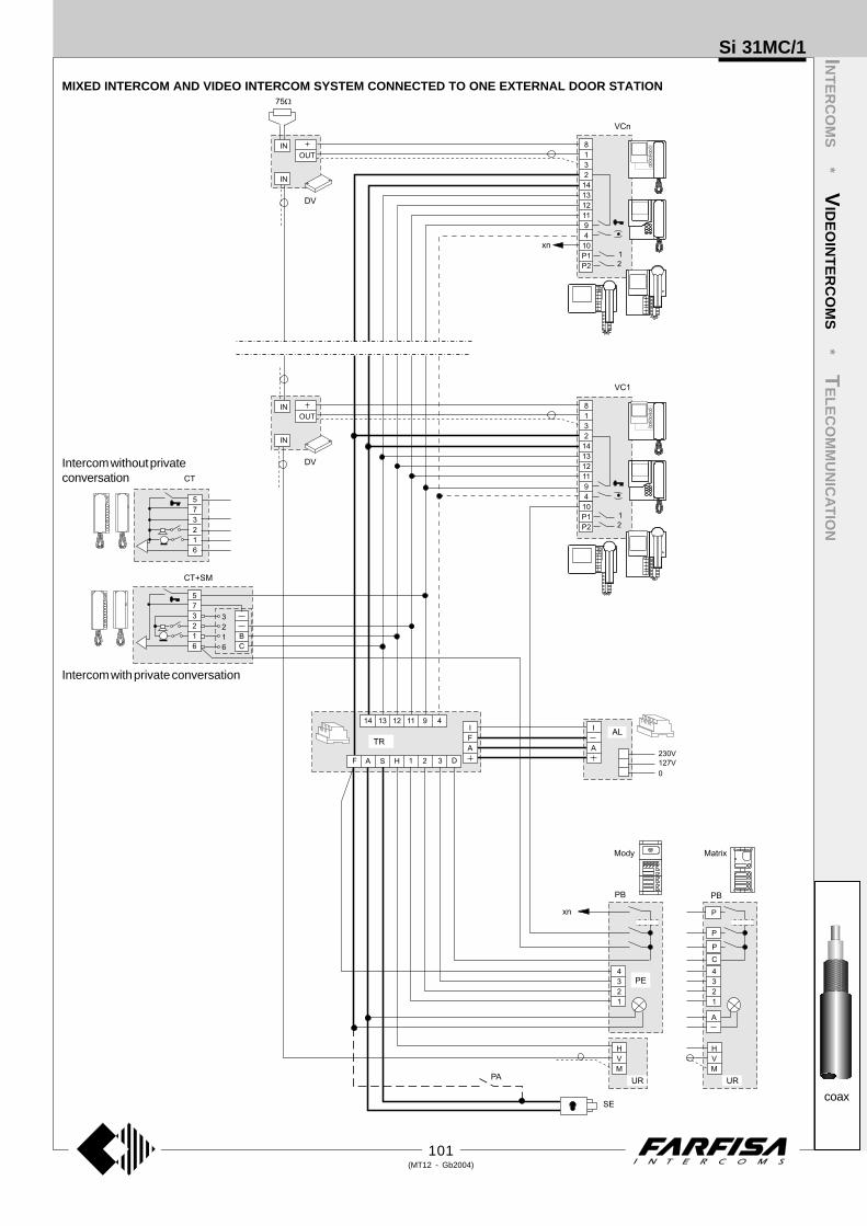
101(MT12 - Gb2004)
INT
ER
CO
MS
* VID
EO
INT
ER
CO
MS
* TE
LE
CO
MM
UN
ICA
TIO
N
coax
Si 31MC/1
MIXED INTERCOM AND VIDEO INTERCOM SYSTEM CONNECTED TO ONE EXTERNAL DOOR STATION
Intercom without privateconversation
Intercom with private conversation

102(MT12 - Gb2004)
INT
ER
CO
MS
* VID
EO
INT
ER
CO
MS
* TE
LE
CO
MM
UN
ICA
TIO
N
coax
VIDEO INTERCOM SYSTEM CONNECTED TO ONE EXTERNAL DOOR STATION WITH SURVEILLANCE CAMERA
Diagram ref. Q.ty Article Description
VC ... PT 5160 + WB 5100 Videointercom FLAT + wall bracketPT 5660 + WB 5600 + 1283 Videointercom + wall bracket + back boxPT 5860 + WB 5600 Videointercom reflex + wall bracketPV 1260 + WB1200 + 1283 Videointercom + wall bracket + back boxPV 2160 + WB 2100 Videointercom FLAT + wall bracket
DV ... DV2-4 Video distributorAL 1 1281 Power supplyTR 1 1382 TimerIN 1 1471 Relay unit (optional)TVT 1 TVT... CCTV cameraH 1 H... Lens with or without autoirisCU 1 CU... Outdoor heated housingAST 1 AST... Bracket for camera or housingAPS 1 APS... Power supply for cameraLL 1 ** Lamp with maximum power 800W (optional)PA 1 ** Door release button (optional)SE 1 ** Electric door lock (12Vac-1A)
External door station
Mody series (for the composition see pages 82÷85)1 row 2 row
PB ... MD72-73-74 MD72-73-74 Back boxes and module frames1 MD10-11-12 MD10-122-124 Modules for electric door speaker... MD21 ÷ 24 MD222 ÷ 228 Button modules... MD20 - 50 MD20 - 50 Blank and info modules1 MD82 ÷ 812 MD82 ÷ 812 Hood covers1 MD92 ÷ 912* MD92 ÷ 912* Rain shelters
PE 1 MD30 MD30 Electric door speaker (amplifier)
Matrix series (for the composition see pages 88÷89)
PB ... MA20-22-24 Blank and button modules... MA61-62-63 Front frames... MA71-72-73 Back boxes and module frames
PE 1 MA10P÷12P Modules with integrated audio amplifier
... Refers to number of users.* The rain shelter is used in the place of the back
box and hood cover.** Articles not supplied by ACI Farfisa.
Working instructions. See page 94.
Notes- If the control switching ON is necessary, con-
nect terminal 4 of the timer (dashed wire).- For the connection of name plate lamps read
notes 6, 7 and 8 of the installation instructionson page 91.
- For wires dimensioning and video connectionrefer to the installation instructions and table onpages 91÷93.
- For one-way systems connect the coaxialcable to the monitor bracket directly, withoutusing the DV video distributor.
- For the selection of CCTV equipment see thegeneral catalogue.
Si 31MO/2
Use expandable fixing bracketsWB5160, WB5660, WB1260,WB2160.
Floor-callThis working diagram allows for differentiat-ing the floor-call from the call from the push-button panel.
Application of MD100 and MD200 modules in one and multiway systems
When using MD100 andMD200 amplified externaldoor stations, it is advis-able to place this diagramon the diagram of page 103and line it up with the riser.For AC powered wires re-fer to the indications onpage 91.

103(MT12 - Gb2004)
INT
ER
CO
MS
* VID
EO
INT
ER
CO
MS
* TE
LE
CO
MM
UN
ICA
TIO
N
coax
VIDEO INTERCOM SYSTEM CONNECTED TO ONE EXTERNAL DOOR STATION WITH SURVEILLANCE CAMERA
Si 31MO/2

104(MT12 - Gb2004)
INT
ER
CO
MS
* VID
EO
INT
ER
CO
MS
* TE
LE
CO
MM
UN
ICA
TIO
N
coax
VIDEO INTERCOM SYSTEM CONNECTED TO TWO EXTERNAL DOOR STATIONS
Diagram ref. Q.ty Article Description
VC ... PT 5160 + WB 5100 Videointercom FLAT + wall bracketPT 5660 + WB 5600 + 1283 Videointercom + wall bracket + back boxPT 5860 + WB 5600 Videointercom reflex + wall bracketPV 1260 + WB1200 + 1283 Videointercom + wall bracket + back boxPV 2160 + WB 2100 Videointercom FLAT + wall bracket
DV ... DV2-4 Video distributorAL 1 1281 Power supplyTR 1 1382 TimerDS 1 1273TV ExchangerPA 2 ** Door release button (optional)SE 2 ** Electric door lock (12Vac-1A)
External door station
Mody series (for the composition see pages 82÷85)1 row 2 row
UR 2 MD41 MD41 Camera modulePB ... MD72-73-74 MD72-73-74 Back boxes and module frames
2 MD10-11-12 MD10-122-124 Modules for electric door speaker... MD21 ÷ 24 MD222 ÷ 228 Button modules... MD20 - 50 MD20 - 50 Blank and info modules2 MD82 ÷ 812 MD82 ÷ 812 Hood covers2 MD92 ÷ 912* MD92 ÷ 912* Rain shelters
PE 2 MD30 MD30 Electric door speaker
Matrix series (for the composition see pages 88÷89)
UR 2 MA42-43 Camera modules with integrated audio amplifierPB ... MA20-22-24 Blank and button modules
... MA61-62-63 Front frames
... MA71-72-73 Back boxes and module frames
... Refers to number of users.* The rain shelter is used in the place of the back box and hood cover.** Articles not supplied by ACI Farfisa.
Notes- To have the control switch ON for the 2 video
entrances it is necessary to make the dashedline connections and use WB5160, WB5660,WB2160, WB1260 wall brackets. The wallbrackets are configurated to work without theaudio privacy, to restore it the jumper J1must be moved (see pages 73, 75, 77, 79and 80).
- For the connection of name plate lamps readnotes 6, 7 and 8 of the installation instructionson page 91.
- For wires dimensioning and video connec-tion refer to the installation instructions andtable on pages 91÷93.
- For one-way systems connect the coaxialcable to the monitor bracket directly, withoutusing the DV video distributor.
Working instructionsIt is similar to the basic system described onpage 94, but with the following variations:- The audio-video operations and the door lockrelease are automatically switched at the timeof the call or with the control switch ON.
Si 32MO/1
Use expandable fixing bracketsWB5160, WB5660, WB1260,WB2160.
Floor-callThis working diagram allows for differentiat-ing the floor-call from the call from the push-button panel.
Connection of 2 door locks withsimultaneous openingIf it is necessary to operate the 2 doorlocks of the system at the same time,you must:- add a 12Vac transformer with suit-
able power (type PRS210)- add a 12Vac relay (type 1471)- make the connections as shown in
the diagram below.
Control switching ON deactivationTo activate the control switching ON from thevideointercoms only when the system is in standby,it is necessary to install a 2-exchange relay (type1472) and connect it as shown on the diagram.
To 9 of the videointercoms
VC is a reference on the diagrams

105(MT12 - Gb2004)
INT
ER
CO
MS
* VID
EO
INT
ER
CO
MS
* TE
LE
CO
MM
UN
ICA
TIO
N
coax
VIDEO INTERCOM SYSTEM CONNECTED TO TWO EXTERNAL DOOR STATIONS
Si 32MO/1

106(MT12 - Gb2004)
INT
ER
CO
MS
* VID
EO
INT
ER
CO
MS
* TE
LE
CO
MM
UN
ICA
TIO
N
coax
VIDEO INTERCOM SYSTEM CONNECTED TO TWO EXTERNAL DOOR STATIONS, ONE OF WHICH ONLY AUDIO
Diagram ref. Q.ty Article Description
VC ... PT 5160 + WB 5100 Videointercom FLAT + wall bracketPT 5660 + WB 5600 + 1283 Videointercom + wall bracket + back boxPT 5860 + WB 5600 Videointercom reflex + wall bracketPV 1260 + WB1200 + 1283 Videointercom + wall bracket + back boxPV 2160 + WB 2100 Videointercom FLAT + wall bracket
DV ... DV2-4 Video distributorAL 1 1281 Power supplyTR 1 1382 TimerDS 1 1473 ExchangerPA 2 ** Door release button (optional)SE 2 ** Electric door lock (12Vac-1A)
External door station
Mody series (for the composition see pages 82÷85)1 row 2 row
UR 1 MD41 MD41 Camera modulePB ... MD72-73-74 MD72-73-74 Back boxes and module frames
2 MD10-11-12 MD10-122-124 Modules for electric door speaker... MD21 ÷ 24 MD222 ÷ 228 Button modules... MD20 - 50 MD20 - 50 Blank and info modules2 MD82 ÷ 812 MD82 ÷ 812 Hood covers2 MD92 ÷ 912* MD92 ÷ 912* Rain shelters
PE 2 MD30 MD30 Electric door speaker (amplifier)
Matrix series (for the composition see pages 88÷89)
UR 1 MA42-43 Camera modules with integrated audio amplifierPE 1 MA10P÷MA12P Modules with integrated audioPB ... MA20-22-24 Blank and button modules
... MA61-62-63 Front frames
... MA71-72-73 Back boxes and module frames
... Refers to number of users.* The rain shelter is used in the place of the
back box and hood cover.** Articles not supplied by ACI Farfisa.
Notes- If the control switching ON is necessary, con-
nect terminal 4 of the timer (dashed wire).- For the connection of name plate lamps read
notes 6, 7 and 8 of the installation instructionson page 91.
- For wires dimensioning and video connec-tion refer to the installation instructions andtable on pages 91÷93.
- For one-way systems connect the coaxialcable to the monitor bracket directly, withoutusing the DV video distributor.
Working instructionsIt is similar to the basic system described onpage 94, but with the following variations:-Carrying out a call from the entrance onlyaudio, the corresponding monitor turns itselfON without images.
-The audio-video operations and the doorlock release are automatically switched at thetime of the call or with the control switch ON.
Si 32MO/2
Use expandable fixing bracketsWB5160, WB5660, WB1260,WB2160.
Floor-callThis working diagram allows for differentiat-ing the floor-call from the call from the push-button panel.
Connection of 2 door locks withsimultaneous openingIf it is necessary to operate the 2 doorlocks of the system at the same time,you must:- add a 12Vac transformer with suit-
able power (type PRS210)- add a 12Vac relay (type 1471)- make the connections as shown in
the diagram below.
Control switching ON deactivationTo activate the control switching ON from thevideointercoms only when the system is in standby,it is necessary to install a relay (type 1471 or 1472)and connect it as shown on the diagram.
To 9 of the videointercoms
VC is a reference on the diagrams

107(MT12 - Gb2004)
INT
ER
CO
MS
* VID
EO
INT
ER
CO
MS
* TE
LE
CO
MM
UN
ICA
TIO
N
coax
VIDEO INTERCOM SYSTEM CONNECTED TO TWO EXTERNAL DOOR STATIONS, ONE OF WHICH ONLY AUDIO
Si 32MO/2

108(MT12 - Gb2004)
INT
ER
CO
MS
* VID
EO
INT
ER
CO
MS
* TE
LE
CO
MM
UN
ICA
TIO
N
coax
VIDEO INTERCOM SYSTEM CONNECTED TO THREE EXTERNAL DOOR STATIONS
Diagram ref. Q.ty Article Description
VC ... PT 5160 + WB 5100 Videointercom FLAT + wall bracketPT 5660 + WB 5600 + 1283 Videointercom + wall bracket + back boxPT 5860 + WB 5600 Videointercom reflex + wall bracketPV 1260 + WB1200 + 1283 Videointercom + wall bracket + back boxPV 2160 + WB 2100 Videointercom FLAT + wall bracket
DV ... DV2-4 Video distributorAL 1 1281 Power supplyTR 1 1382 TimerDS 2 1273TV ExchangerPA 3 ** Door release button (optional)SE 3 ** Electric door lock (12Vac-1A)
External door station
Mody series (for the composition see pages 82÷85)1 row 2 row
UR 3 MD41 MD41 Camera modulePB ... MD72-73-74 MD72-73-74 Back boxes and module frames
3 MD10-11-12 MD10-122-124 Modules for electric door speaker... MD21 ÷ 24 MD222 ÷ 228 Button modules... MD20 - 50 MD20 - 50 Blank and info modules3 MD82 ÷ 812 MD82 ÷ 812 Hood covers3 MD92 ÷ 912* MD92 ÷ 912* Rain shelters
PE 3 MD30 MD30 Electric door speaker (amplifier)
Matrix series (for the composition see pages 88÷89)
UR 3 MA42-43 Camera modules with integrated audio amplifierPB ... MA20-22-24 Blank and button modules
... MA61-62-63 Front frames
... MA71-72-73 Back boxes and module frames
... Refers to number of users.* The rain shelter is used in the place of the back box and hood cover.** Articles not supplied by ACI Farfisa.
Notes- To have the control switch ON for the 3 video
entrances it is necessary to make the dashedline connections and use WB5160, WB5660,WB2160, WB1260 wall brackets. The wallbrackets are configurated to work without theaudio privacy, to restore it the jumper J1must be moved (see pages 73, 75, 77, 79and 80).
- For the connection of name plate lamps readnotes 6, 7 and 8 of the installation instructionson page 91.
- For wires dimensioning and video connec-tion refer to the installation instructions andtable on pages 91÷93.
- For one-way systems connect the coaxialcable to the monitor bracket directly, withoutusing the DV video distributor.
Working instructionsIt is similar to the basic system described onpage 94, but with the following variations:-The audio-video operations and the door lockrelease are automatically switched at the timeof the call or with the control switch ON.
Si 33MO/1
Use expandable fixing bracketsWB5160, WB5660, WB1260,WB2160.
Floor-callThis working diagram allows for differentiat-ing the floor-call from the call from the push-button panel.
Control switching ON deacti-vationTo activate the control switchingON from the videointercoms onlywhen the system is in standby, it isnecessary to install a 2-exchangerelay (type 1472) and connect itas shown on the diagram.
VC, DS1 and DS2 are a reference onthe diagrams

109(MT12 - Gb2004)
INT
ER
CO
MS
* VID
EO
INT
ER
CO
MS
* TE
LE
CO
MM
UN
ICA
TIO
N
coax
VIDEO INTERCOM SYSTEM CONNECTED TO THREE EXTERNAL DOOR STATIONS
Si 33MO/1

110(MT12 - Gb2004)
INT
ER
CO
MS
* VID
EO
INT
ER
CO
MS
* TE
LE
CO
MM
UN
ICA
TIO
N
coax
VIDEO INTERCOM SYSTEM CONNECTED TO THREE EXTERNAL DOOR STATIONS, ONE OF WHICH ONLY AUDIO
Diagram ref. Q.ty Article Description
VC ... PT 5160 + WB 5100 Videointercom FLAT + wall bracketPT 5660 + WB 5600 + 1283 Videointercom + wall bracket + back boxPT 5860 + WB 5600 Videointercom reflex + wall bracketPV 1260 + WB1200 + 1283 Videointercom + wall bracket + back boxPV 2160 + WB 2100 Videointercom FLAT + wall bracket
DV ... DV2-4 Video distributorAL 1 1281 Power supplyTR 1 1382 TimerDS1 1 1473 ExchangerDS2 1 1273TV ExchangerPA 3 ** Door release button (optional)SE 3 ** Electric door lock (12Vac-1A)
External door station
Mody series (for the composition see pages 82÷85)1 row 2 row
UR 2 MD41 MD41 Camera modulePB ... MD72-73-74 MD72-73-74 Back boxes and module frames
3 MD10-11-12 MD10-122-124 Modules for electric door speaker... MD21 ÷ 24 MD222 ÷ 228 Button modules... MD20 - 50 MD20 - 50 Blank and info modules3 MD82 ÷ 812 MD82 ÷ 812 Hood covers3 MD92 ÷ 912* MD92 ÷ 912* Rain shelters
PE 3 MD30 MD30 Electric door speaker (amplifier)
Matrix series (for the composition see pages 88÷89)
UR 2 MA42-43 Camera modules with integrated audio amplifierPE 1 MA10P÷12P Modules with integrated audioPB ... MA20-22-24 Blank and button modules
... MA61-62-63 Front frames
... MA71-72-73 Back boxes and module frames
Si 33MO/2
... Refers to number of users.* The rain shelter is used in the place of the back
box and hood cover.** Articles not supplied by ACI Farfisa.
Notes- To have the control switch ON for the 2 video
entrances it is necessary to make the dashedline connections and use WB5160, WB5660,WB2160, WB1260 wall brackets. The wallbrackets are configurated to work without theaudio privacy, to restore it the jumper J1 mustbe moved (see pages 73, 75, 77, 79 and 80).
- For the connection of name plate lamps readnotes 6, 7 and 8 of the installation instructions onpage 91.
- For wires dimensioning and video connectionrefer to the installation instructions and table onpages 91÷93.
- For one-way systems connect the coaxialcable to the monitor bracket directly, withoutusing the DV video distributor.
Working instructionsIt is similar to the basic system described on page94, but with the following variations:-Carrying out a call from the entrance only audio,the corresponding monitor turns itself ON withoutimages.
-The audio-video operations and the door lockrelease are automatically switched at the time ofthe call or with the control switch ON.
Use expandable fixing bracketsWB5160, WB5660, WB1260,WB2160.
Floor-callThis working diagram allows for differentiat-ing the floor-call from the call from the push-button panel.
Control switching ON deactivationTo activate the control switching ON from thevideointercoms only when the system is instandby, it is necessary to install a 2-exchangerelay (type 1472) and connect it as shown on thediagram.
VC and DS2 are a reference on the diagrams

111(MT12 - Gb2004)
INT
ER
CO
MS
* VID
EO
INT
ER
CO
MS
* TE
LE
CO
MM
UN
ICA
TIO
N
coax
VIDEO INTERCOM SYSTEM CONNECTED TO THREE EXTERNAL DOOR STATIONS, ONE OF WHICH ONLY AUDIO
Si 33MO/2

112(MT12 - Gb2004)
INT
ER
CO
MS
* VID
EO
INT
ER
CO
MS
* TE
LE
CO
MM
UN
ICA
TIO
N
coax
VIDEO INTERCOM SYSTEM CONNECTED TO THREE EXTERNAL DOOR STATIONS, TWO OF WHICH ONLY AUDIO
Diagram ref. Q.ty Article Description
VC ... PT 5160 + WB 5100 Videointercom FLAT + wall bracketPT 5660 + WB 5600 + 1283 Videointercom + wall bracket + back boxPT 5860 + WB 5600 Videointercom reflex + wall bracketPV 1260 + WB1200 + 1283 Videointercom + wall bracket + back boxPV 2160 + WB 2100 Videointercom FLAT + wall bracket
DV ... DV2-4 Video distributorAL 1 1281 Power supplyTR 1 1382 TimerDS 2 1473 ExchangerPA 3 ** Door release button (optional)SE 3 ** Electric door lock (12Vac-1A)
External door station
Mody series (for the composition see pages 82÷85)1 row 2 row
UR 1 MD41 MD41 Camera modulePB ... MD72-73-74 MD72-73-74 Back boxes and module frames
3 MD10-11-12 MD10-122-124 Modules for electric door speaker... MD21 ÷ 24 MD222 ÷ 228 Button modules... MD20 - 50 MD20 - 50 Blank and info modules3 MD82 ÷ 812 MD82 ÷ 812 Hood covers3 MD92 ÷ 912* MD92 ÷ 912* Rain shelters
PE 3 MD30 MD30 Electric door speaker (amplifier)
Matrix series (for the composition see pages 88÷89)
UR 1 MA42-43 Camera modules with integrated audio amplifierPE 2 MA10P÷12P Modules with integrated audioPB ... MA20-22-24 Blank and button modules
... MA61-62-63 Front frames
... MA71-72-73 Back boxes and module frames
Si 33MO/7
... Refers to number of users.* The rain shelter is used in the place of the
back box and hood cover.** Articles not supplied by ACI Farfisa.
Notes- If the control switching ON is necessary, con-
nect terminal 4 of the timer (dashed wire).- For the connection of name plate lamps read
notes 6, 7 and 8 of the installation instructionson page 91.
- For wires dimensioning and video connec-tion refer to the installation instructions andtable on pages 91÷93.
- For one-way systems connect the coaxialcable to the monitor bracket directly, withoutusing the DV video distributor.
Working instructionsIt is similar to the basic system described onpage 94, but with the following variations:-Carrying out a call from the entrance onlyaudio, the corresponding monitor turns itselfON without images.
-The audio-video operations and the door lockrelease are automatically switched at the timeof the call or with the control switch ON.
Use expandable fixing bracketsWB5160, WB5660, WB1260,WB2160.
Floor-callThis working diagram allows for differentiat-ing the floor-call from the call from the push-button panel.
Control switching ON deactivationTo activate the control switching ON from thevideointercoms only when the system is in standby,it is necessary to install a relay (type 1471 or 1472)and connect it as shown on the diagram.
VC and DS2 are a reference on the diagrams
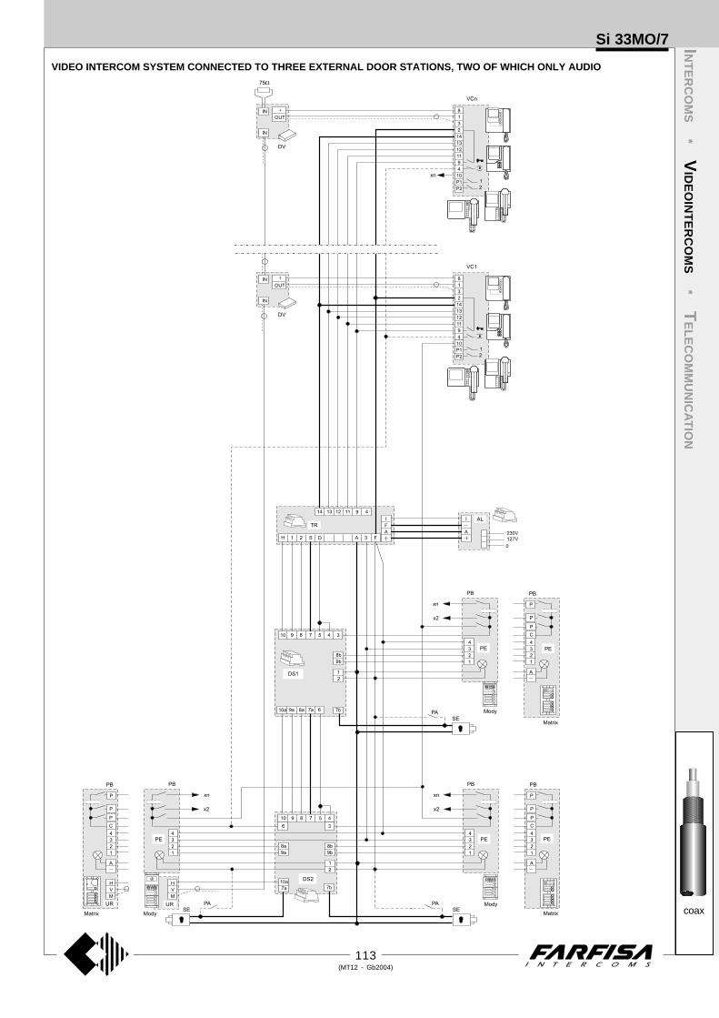
113(MT12 - Gb2004)
INT
ER
CO
MS
* VID
EO
INT
ER
CO
MS
* TE
LE
CO
MM
UN
ICA
TIO
N
coax
VIDEO INTERCOM SYSTEM CONNECTED TO THREE EXTERNAL DOOR STATIONS, TWO OF WHICH ONLY AUDIO
Si 33MO/7

114(MT12 - Gb2004)
INT
ER
CO
MS
* VID
EO
INT
ER
CO
MS
* TE
LE
CO
MM
UN
ICA
TIO
N
coax
VIDEO INTERCOM SYSTEM WITH SECONDARY VIDEO STATIONS AND 1 MAIN COMMON VIDEO STATION (multiple entrance)
Diagram ref. Q.ty Article Description
VC ... PT 5160 + WB 5100 Videointercom FLAT + wall bracketPT 5660 + WB 5600 + 1283 Videointercom + wall bracket + back boxPT 5860 + WB 5600 Videointercom reflex + wall bracketPV 1260 + WB1200 + 1283 Videointercom + wall bracket + back boxPV 2160 + WB 2100 Videointercom FLAT + wall bracket
DV ... DV2-4 Video distributorAV 1 476 Video distributorAL 1+X 1281 Power supplyTR 1+X 1382 TimerDS X 1273TV ExchangerPA 1+X ** Door release button (optional)SE 1+X ** Electric door lock (12Vac-1A)
External door station
Mody series (for the composition see pages 82÷85)1 row 2 row
UR 1+X MD41 MD41 Camera modulePB ... MD72-73-74 MD72-73-74 Back boxes and module frames
1+X MD10-11-12 MD10-122-124 Modules for electric door speaker... MD21 ÷ 24 MD222 ÷ 228 Button modules... MD20 - 50 MD20 - 50 Blank and info modules1+X MD82 ÷ 812 MD82 ÷ 812 Hood covers1+X MD92 ÷ 912* MD92 ÷ 912* Rain shelters
PE 1+X MD30 MD30 Electric door speaker (amplifier)
Matrix series (for the composition see pages 88÷89)
UR 1+X MA42-43 Camera modules with integrated audio amplifierPB ... MA20-22-24 Blank and button modules
... MA61-62-63 Front frames
... MA71-72-73 Back boxes and module frames
... Refers to number of users.X Refers to number of secondary door stations.* The rain shelter is used in the place of the back box and hood cover.** Articles not supplied by ACI Farfisa.
Notes- Connect the video intercom terminal 4 (wire
shown with dotted line) if the control switch onfrom the secondary door station is required.
- For the connection of name plate lamps readnotes 6, 7 and 8 of the installation instructionson page 91.
- For wires dimensioning and video connec-tion refer to the installation instructions andtable on pages 91÷93.
Si 36MO/2
Connection of two door locks, of whichthe secondary is always activable, in asystem with multiple entrance
For this option it is necessary to install adiode (100V-1A; type 1N4007) betweenterminals 7 (cathode) and 7a (anode) ofevery secondary exchanger.
common of buttons 1and 2
to separate the com-mon of buttons cut here
common of buttons 3and 4
The main entrance push-button panelmust have separate common terminals.One common terminal for each secondarydoor station. Buttons of the Mody series canbe divided into 2-button groups.
Use expandable fixing bracketsWB5160, WB5660, WB1260,WB2160.
Floor-callThis working diagram allows for differentiat-ing the floor-call from the call from the push-button panel.
Control switching ON deactivationTo activate the control switching ON from thevideointercoms only when the system is in standby,it is necessary to install a relay (type 1471 or 1472)and connect it as shown on the diagram.
Working instructionsIt is similar to the basic system described onpage 94, but with the following variations:-The audio-video operations and the doorlock release are automatically switched atthe time of the call or with the control switchON.
-The services towards the secondary videoentrances are independent among them-selves and therefore they can function at thesame time.
VC and DS are a reference on the diagrams

115(MT12 - Gb2004)
INT
ER
CO
MS
* VID
EO
INT
ER
CO
MS
* TE
LE
CO
MM
UN
ICA
TIO
N
coax
VIDEO INTERCOM SYSTEM WITH SECONDARY VIDEO STATIONS AND 1 MAIN COMMON VIDEO STATION (multiple entrance)
Si 36MO/2
Application of Matrixpush-button panel
The button commonterminal of every moduleCANNOT be separated.For the composition of thepush-button panel at themain entrance, carefullyselect the button modulesin order to obtain thenecessary number ofbuttons for every com-mon terminal.

116(MT12 - Gb2004)
INT
ER
CO
MS
* VID
EO
INT
ER
CO
MS
* TE
LE
CO
MM
UN
ICA
TIO
N
coax
VIDEO INTERCOM SYSTEM WITH SECONDARY DOOR STATIONS ONLY AUDIO AND 1 MAIN COMMON VIDEO STATION (multipleentrance)
Diagram ref. Q.ty Article Description
VC ... PT 5160 + WB 5100 Videointercom FLAT + wall bracketPT 5660 + WB 5600 + 1283 Videointercom + wall bracket + back boxPT 5860 + WB 5600 Videointercom reflex + wall bracketPV 1260 + WB1200 + 1283 Videointercom + wall bracket + back boxPV 2160 + WB 2100 Videointercom FLAT + wall bracket
DV ... DV2-4 Video distributorAV 1 476 Video distributorAL 1+X 1281 Power supplyTR 1+X 1382 TimerDS X 1273TV ExchangerPA 1+X ** Door release button (optional)SE 1+X ** Electric door lock (12Vac-1A)
External door station
Mody series (for the composition see pages 82÷85)1 row 2 row
UR 1 MD41 MD41 Camera modulePB ... MD72-73-74 MD72-73-74 Back boxes and module frames
1+X MD10-11-12 MD10-122-124 Modules for electric door speaker... MD21 ÷ 24 MD222 ÷ 228 Button modules... MD20 - 50 MD20 - 50 Blank and info modules1+X MD82 ÷ 812 MD82 ÷ 812 Hood covers1+X MD92 ÷ 912* MD92 ÷ 912* Rain shelters
PE 1+X MD30 MD30 Electric door speaker (amplifier)
Matrix series (for the composition see pages 88÷89)
UR 1 MA42-43 Camera modules with integrated audio amplifierPE X MA10P÷MA12P Blank and button modulesPB ... MA20-22-24 Blank and button modules
... MA61-62-63 Front frames
... MA71-72-73 Back boxes and module frames
... Refers to number of users.X Refers to number of secondary door stations.* The rain shelter is used in the place of the back box and hood cover.** Articles not supplied by ACI Farfisa.
Si 36MO/3
Connection of two door locks, of whichthe secondary is always activable, in asystem with multiple entrance
For this option it is necessary to install adiode (100V-1A; type 1N4007) betweenterminals 7 (cathode) and 7a (anode) ofevery secondary exchanger.
Use expandable fixing bracketsWB5160, WB5660, WB1260,WB2160.
Floor-callThis working diagram allows for differentiat-ing the floor-call from the call from the push-button panel.
Notes- For the connection of name plate lamps read
notes 6, 7 and 8 of the installation instructionson page 91.
- For wires dimensioning and video connec-tion refer to the installation instructions andtable on pages 91÷93.
Working instructionsIt is similar to the basic system described onpage 94, but with the following variations:-Carrying out a call from the entrance onlyaudio, the corresponding monitor turns itselfON without images.
-The audio-video operations and the doorlock release are automatically switched atthe time of the call or with the control switchON.
-The services towards the secondary videoentrances are independent among them-selves and therefore they can function at thesame time.
common of buttons 1and 2
to separate the com-mon of buttons cut here
common of buttons 3and 4
The main entrance push-button panelmust have separate common terminals.One common terminal for each secondarydoor station. Buttons of the Mody series canbe divided into 2-button groups.

117(MT12 - Gb2004)
INT
ER
CO
MS
* VID
EO
INT
ER
CO
MS
* TE
LE
CO
MM
UN
ICA
TIO
N
coax
VIDEO INTERCOM SYSTEM WITH SECONDARY DOOR STATIONS ONLY AUDIO AND 1 MAIN COMMON VIDEO STATION (multipleentrance)
Si 36MO/3
Application of Matrixpush-button panel
The button commonterminal of every moduleCANNOT be separated.For the composition of thepush-button panel at themain entrance, carefullyselect the button modulesin order to obtain thenecessary number ofbuttons for every com-mon terminal.

118(MT12 - Gb2004)
INT
ER
CO
MS
* VID
EO
INT
ER
CO
MS
* TE
LE
CO
MM
UN
ICA
TIO
N
coax
VIDEO INTERCOM SYSTEM WITH SECONDARY VIDEO STATIONS AND 1 MAIN COMMON STATION ONLY AUDIO (multiple entrance)
Diagram ref. Q.ty Article Description
VC ... PT 5160 + WB 5100 Videointercom FLAT + wall bracketPT 5660 + WB 5600 + 1283 Videointercom + wall bracket + back boxPT 5860 + WB 5600 Videointercom reflex + wall bracketPV 1260 + WB1200 + 1283 Videointercom + wall bracket + back boxPV 2160 + WB 2100 Videointercom FLAT + wall bracket
DV ... DV2-4 Video distributorAL 1+X 1281 Power supplyTR 1+X 1382 TimerDS X 1273TV ExchangerPA 1+X ** Door release button (optional)SE 1+X ** Electric door lock (12Vac-1A)
External door station
Mody series (for the composition see pages 82÷85)1 row 2 row
UR X MD41 MD41 Camera modulePB ... MD72-73-74 MD72-73-74 Back boxes and module frames
1+X MD10-11-12 MD10-122-124 Modules for electric door speaker... MD21 ÷ 24 MD222 ÷ 228 Button modules... MD20 - 50 MD20 - 50 Blank and info modules1+X MD82 ÷ 812 MD82 ÷ 812 Hood covers1+X MD92 ÷ 912* MD92 ÷ 912* Rain shelters
PE 1+X MD30 MD30 Electric door speaker (amplifier)
Matrix series (for the composition see pages 88÷89)
UR X MA42-43 Camera modules with integrated audio amplifierPE 1 MA10P÷MA12P Modules with integrated audio amplifierPB ... MA20-22-24 Blank and button modules
... MA61-62-63 Front frames
... MA71-72-73 Back boxes and module frames
... Refers to number of users.X Refers to number of secondary door stations.* The rain shelter is used in the place of the back box and hood cover.** Articles not supplied by ACI Farfisa.
Notes- Connect the video intercom terminal 4 (wire
shown with dotted line) if the control switch onfrom the secondary door station is required.
- For the connection of name plate lamps readnotes 6, 7 and 8 of the installation instructionson page 91.
- For wires dimensioning and video connec-tion refer to the installation instructions andtable on pages 91÷93.
Si 36MO/4
Connection of two door locks, of whichthe secondary is always activable, in asystem with multiple entrance
For this option it is necessary to install adiode (100V-1A; type 1N4007) betweenterminals 7 (cathode) and 7a (anode) ofevery secondary exchanger.
Use expandable fixing bracketsWB5160, WB5660, WB1260,WB2160.
Floor-callThis working diagram allows for differentiat-ing the floor-call from the call from the push-button panel.
Working instructionsIt is similar to the basic system described onpage 94, but with the following variations:-Carrying out a call from the entrance onlyaudio, the corresponding monitor turns it-self ON without images.
-The audio-video operations and the doorlock release are automatically switched atthe time of the call or with the control switchON.
-The services towards the secondary videoentrances are independent among them-selves and therefore they can function at thesame time.
Control switching ON deactivationTo activate the control switching ON from thevideointercoms only when the system is in standby,it is necessary to install a relay (type 1471 or 1472)and connect it as shown on the diagram.
VC and DS are a reference on the diagrams
common of buttons 1and 2
to separate the com-mon of buttons cut here
common of buttons 3and 4
The main entrance push-button panelmust have separate common terminals.One common terminal for each secondarydoor station. Buttons of the Mody series canbe divided into 2-button groups.

119(MT12 - Gb2004)
INT
ER
CO
MS
* VID
EO
INT
ER
CO
MS
* TE
LE
CO
MM
UN
ICA
TIO
N
coax
VIDEO INTERCOM SYSTEM WITH SECONDARY VIDEO STATIONS AND 1 MAIN COMMON STATION ONLY AUDIO (multiple entrance)
Si 36MO/4
Application of Matrixpush-button panel
The button commonterminal of every moduleCANNOT be separated.For the composition of thepush-button panel at themain entrance, carefullyselect the button modulesin order to obtain thenecessary number ofbuttons for every com-mon terminal.

120(MT12 - Gb2004)
INT
ER
CO
MS
* VID
EO
INT
ER
CO
MS
* TE
LE
CO
MM
UN
ICA
TIO
N
coax
VIDEO INTERCOM SYSTEM WITH ONE-WAY SECONDARY DOOR STATIONS ONLY AUDIO AND 1 MAIN COMMON VIDEO STATION(multiple entrance)
Diagram ref. Q.ty Article Description
VC ... PT 5160 + WB 5160 Videointercom FLAT + wall bracketPT 5660 + WB 5660 + 1283 Videointercom + wall bracket + back boxPT 5860 + WB 5660 Videointercom reflex + wall bracketPV 1260 + WB1260 + 1283 Videointercom + wall bracket + back boxPV 2160 + WB 2160 Videointercom FLAT + wall bracket
AV 1 476 Video distributorALp 1 1281 Power supplyAL X PRS220 Intercom power supplyTR 1 1382 TimerIN X 1471 Relay unitDS X 1473 ExchangerPA 1+X ** Door release button (optional)SE 1+X ** Electric door lock (12Vac-1A)
External door station
Mody series (for the composition see pages 82÷85)1 row 2 row
UR 1 MD41 MD41 Camera modulePB ... MD71÷74 MD72÷74 Back boxes and module frames
1+X MD10-11-12 MD10-122-124 Modules for electric door speaker... MD21 ÷ 24 MD222 ÷ 228 Button modules... MD20 - 50 MD20 - 50 Blank and info modules1+X MD82 ÷ 812 MD82 ÷ 812 Hood covers1+X MD92 ÷ 912* MD92 ÷ 912* Rain shelters
PE 1+X MD30 MD30 Electric door speaker (amplifier)
Matrix series (for the composition see pages 88÷89)
UR 1 MA42-43 Camera modules with integrated audio amplifierPE X MA11P Module with integrated audio amplifierPB ... MA20-22-24 Blank and button modules
... MA61-62-63 Front frames
... MA71-72-73 Back boxes and module frames
... Refers to number of users.X Refers to number of secondary door stations.* The rain shelter is used in the place of the back box and hood cover.** Articles not supplied by ACI Farfisa.
Si 36MO/5
Connection of two door locks, of whichthe secondary is always activable, in asystem with multiple entrance
For this option it is necessary to install adiode (100V-1A; type 1N4007) betweenterminals 7 (cathode) and 7a (anode) ofevery secondary exchanger.
Working instructionsIt is similar to the basic system described on page 94, but with thefollowing variations:-Carrying out a call from the entrance only audio, the correspondingmonitor turns itself ON without images.
-The audio-video operations and the door lock release are automati-cally switched at the time of the call or with the control switch ON.
-The services towards the secondary video entrances are indepen-dent among themselves and therefore they can function at the sametime.
Notes- Connect the video intercom terminal 4 (wire shown with dotted line)
and apply 2 diodes (1N4007 type; 100V-1A) for every secondarydoor station, if the control switch on is required.
- For the connection of name plate lamps read notes 6, 7 and 8 of theinstallation instructions on page 91.
- For wires dimensioning and video connection refer to the installationinstructions and table on pages 91÷93.
- DV.. distributors can be used instead of the video distributors 476 byadding a power supply wire (from + to terminal 8 of every videointercom).
- On bracket of the videointercoms you must move jumper J1 fromposition 2-3 to 1-2. If the private conversation is necessary, use theSi36MO/3 diagram.
Connection of the MD100 amplified external door station to thesecondary door station instead of electric door speaker MD30and module MD11.
1473

121(MT12 - Gb2004)
INT
ER
CO
MS
* VID
EO
INT
ER
CO
MS
* TE
LE
CO
MM
UN
ICA
TIO
N
coax
VIDEO INTERCOM SYSTEM WITH ONE-WAY SECONDARY DOOR STATIONS ONLY AUDIO AND 1 MAIN COMMON VIDEO STATION(multiple entrance)
Si 36MO/5
Application ofMatrix push-button panel
Connect all thecommon "C" ter-minals of themodules to-gether.

122(MT12 - Gb2004)
INT
ER
CO
MS
* VID
EO
INT
ER
CO
MS
* TE
LE
CO
MM
UN
ICA
TIO
N
coax
VIDEO INTERCOM SYSTEM WITH SECONDARY VIDEO STATIONS AND 2 MAIN COMMON VIDEO STATIONS (multiple entrance)
Diagram ref. Q.ty Article Description
VC ... PT 5160 + WB 5100 Videointercom FLAT + wall bracketPT 5660 + WB 5600 + 1283 Videointercom + wall bracket + back boxPT 5860 + WB 5600 Videointercom reflex + wall bracketPV 1260 + WB1200 + 1283 Videointercom + wall bracket + back boxPV 2160 + WB 2100 Videointercom FLAT + wall bracket
DV ... DV2-4 Video distributorAV 2+.. 476 Video distributorAL 2+X 1281 Power supplyTR 1+X 1382 TimerDS 2xX 1273TV ExchangerIN 1 1471 Relay unitD 2 ** Min. 100V-1A diodes (1N4007 type)PA 2+X ** Door release button (optional)SE 2+X ** Electric door lock (12Vac-1A)
External door station
Mody series (for the composition see pages 82÷85)1 row 2 row
UR 2+X MD41 MD41 Camera modulePB ... MD72-73-74 MD72-73-74 Back boxes and module frames
2+X MD10-11-12 MD10-122-124 Modules for electric door speaker... MD21 ÷ 24 MD222 ÷ 228 Button modules... MD20 - 50 MD20 - 50 Blank and info modules2+X MD82 ÷ 812 MD82 ÷ 812 Hood covers2+X MD92 ÷ 912* MD92 ÷ 912* Rain shelters
PE 2+X MD30 MD30 Electric door speaker (amplifier)
Matrix series (for the composition see pages 88÷89)
UR 2+X MA42-43 Camera modules with integrated audio amplifierPB ... MA20-22-24 Blank and button modules
... MA61-62-63 Front frames
... MA71-72-73 Back boxes and module frames
... Refers to number of users.X Refers to number of secondary door sta-
tions.* The rain shelter is used in the place of the
back box and hood cover.** Articles not supplied by ACI Farfisa.
Notes- Connect the video intercom terminal 4 (wire
shown with dotted line) if the control switch onfrom the secondary door station is required.
- For the connection of name plate lamps readnotes 6, 7 and 8 of the installation instructionson page 91.
- For wires dimensioning and video connec-tion refer to the installation instructions and
Si 37MO/1
Connection of two door locks, of whichthe secondary is always activable, in asystem with multiple entrance
For this option it is necessary to install adiode (100V-1A; type 1N4007) betweenterminals 7 (cathode) and 7a (anode) ofevery secondary exchanger.
Use expandable fixing bracketsWB5160, WB5660, WB1260,WB2160.
Floor-callThis working diagram allows for differentiat-ing the floor-call from the call from the push-button panel.
table on pages 91÷93.- To use the Matrix series push-button pan-
els, see the application diagram and noteson page 115, 117 or 119.
Working instructionsIt is similar to the basic system described onpage 94, but with the following variations:-The audio-video operations and the doorlock release are automatically switched atthe time of the call or with the control switchON.
-The services towards the secondary videoentrances are independent among them-selves and therefore they can function at thesame time.
Control switching ON deactivationTo activate the control switching ON from thevideointercoms only when the system is in standby,it is necessary to install a relay (type 1471 or 1472)and connect it as shown on the diagram.
VC and DS1 are a reference on the diagrams
common of buttons 1and 2
to separate the com-mon of buttons cut here
common of buttons 3and 4
The main entrance push-button panelmust have separate common terminals.One common terminal for each secondarydoor station. Buttons of the Mody series canbe divided into 2-button groups.

123(MT12 - Gb2004)
INT
ER
CO
MS
* VID
EO
INT
ER
CO
MS
* TE
LE
CO
MM
UN
ICA
TIO
N
coax
VIDEO INTERCOM SYSTEM WITH SECONDARY VIDEO STATIONS AND 2 MAIN COMMON VIDEO STATIONS (multiple entrance)
Si 37MO/1

124(MT12 - Gb2004)
INT
ER
CO
MS
* VID
EO
INT
ER
CO
MS
* TE
LE
CO
MM
UN
ICA
TIO
N
coax
All installation diagrams in this technical manual are drawn with only one video intercom for each user. It is possible to “personalise” the installationby properly matching the applications on the following pages (page 126 to 148) to the basic diagrams (page 99 to page 123). Such examples referto applications with one video intercom entrance. To realise systems with 2 or more audio/video entrances were more than one control switch ONis needed, use for this function the first buttons of the video intercom (P, P1, P2, etc.) and the lower ones (P3, P4, etc.) for the intercommunicatingcalls.In the basic diagrams the dashed lines identify the wires for control switch ON, whereas in the additional diagrams the dashed lines also refer tothe wires for intercommunicating service.When the simultaneous switch ON of several video intercoms is needed and extra power supplies are to be added, do not forget that terminal Iof timer 1382 can be connected to a maximum of 3 power supplies 1281.
EXTENSION OF VIDEO INTERCOM SYSTEMS
Additional diagrams
NOTES1) To have the intercommunication system you must:
a) - make the connections shown with dotted lines,b) - apply the module 1443E inside the timer 1382 (see page 90),c) - use expandable brackets WB5160, WB5660, WB1260, WB2160, verifying that themobile jumper J1 located on the video intercom brackets is in intercommunicatingposition 1-2 (see page 73, 75, 77, 79 and 80).
2) In intercommunicating intercoms you must:- cut the jumper W1,- add the electronic buzzer SR40,- add the necessary number of PT501 button groups andconnect one of the two terminals to terminal 7 of the intercom.
3) If the video system is realized with coaxial cableconnected in serial mode (input and output from thevideo intercom), you must cut the 75Ω resistanceof the bracket and leave itonly on the last video inter-com.
4) When using the video in-tercom PV2160 the addi-tional buttons P1, P2, P3,P4 and P5 change into T1, T2, T3, T4 and T5,respectively (T6 does not exist because the maxi-mum number of additional buttons is 5).
5) The diode shown in this installation diagram mustbe connected to power video distributors DV2 andDV4. The diode is not necessary if no videodistributors are used.
Example of combination of an additional dia-gram with a basic diagram for the realisation of aone-way system with intercoms and video inter-coms in parallel with or without intercommunicat-ing service (description on page 125).
W1
1
PT 520
SR 40X2
79
X1

125(MT12 - Gb2004)
INT
ER
CO
MS
* VID
EO
INT
ER
CO
MS
* TE
LE
CO
MM
UN
ICA
TIO
N
coax
Extension of ONE-WAY system
To realise a one-way system with several monitors and/orintercoms in parallel, with or without intercommunicatingservice, you must proceed as follows:
- make a photocopy of the additional diagram desired, se-lecting it among those of pages 126 to 136;
- place the diagram on the basic diagram so as to cover theexisting video intercom and line up the wires of the twodiagrams;
- if specified in the additional diagram, connect the wires I andX1 to terminals I and A of art. 1382;
- to have the intercommunication system you must:- make the connections shown with dotted lines,- apply the module 1443E inside the timer 1382,- use expandable brackets WB5160, WB5660, WB1260,WB2160, verifying that the mobile jumper J1 located onthe video intercom brackets is in intercommunicating position1-2 (see page 73, 75, 77, 79 and 80).
- add the electronic buzzer SR40 and the necessary numberof buttons PT501 in the intercoms, if any.
Example (see page 124): by making a photocopy of theadditional diagram of page 127 (3 video intercoms and 1intercom in parallel with or without intercommunicating ser-vice), placing it on the installation diagram of page 105 (Si32MO/1), lining it up to the wires of the first video intercom andeliminating the secondvideo intercom and thevideo distributor, it ispossible to obtain a one-way system with 3 videointercoms and 1 inter-com in parallel con-nected to 2 externalvideo stations.
EXTENSION OF VIDEO INTERCOM SYSTEMS
Additional diagrams
Extension in one apartment of a MULTI-WAY system
To realise a multi-way system with several video intercoms and/or intercoms inparallel in one apartment with or without intercommunicating service, youmust proceed as follows:
- make a photocopy of the additional diagram desired, selecting it among thoseof pages 137 to 148;
- place the diagram on the basic diagram so as to cover the existing videointercom and line up the wires of the two diagrams;
- to have the intercommunication system you must:- make the connections shown with dotted lines,- use expandable brackets WB5160, WB5660, WB1260, WB2160, verifyingthat the mobile jumper J1 located on the video intercom brackets is inintercommunicating position 1-2 (see page 73, 75, 77, 79 and 80).
- add the electronic buzzer SR40 and the necessary number of buttons PT501 inthe intercoms, if any.
Example: by making a photocopy of the additional diagram of page 137 (2videointercoms and 1 intercom in parallel with or without intercommunicatingservice), placing it on the installation diagram of page 105 (Si 32MO/1), lining it upto the wires of the first video intercom, it is possible to obtain a multi-way systemwith 2 video intercoms and 1 intercom in parallel in one apartment and intercom-municating connected to 2 external video stations.
Extension of a MULTI-WAY system in several apartmentsTo realise a multi-way system with several video intercoms and/or intercoms inparallel in 2 or more apartments with or without intercommunicating service,you must repeat the operations described in the preceding section several times.
Example of combina-tion of an additional dia-gram with a basic dia-gram for the realisationof a multi-way systemwith extension in oneapartment only.

126(MT12 - Gb2004)
INT
ER
CO
MS
* VID
EO
INT
ER
CO
MS
* TE
LE
CO
MM
UN
ICA
TIO
N
coax
ONE-WAY additional diagrams
1 VIDEO INTERCOM AND 1 INTERCOM WITH INTERCOMMUNI-CATING SERVICE
2 INTERCOMMUNICATING VIDEO INTERCOMS
1 VIDEO INTERCOM AND 2 INTERCOMS WITH INTERCOMMU-NICATING SERVICE
2 VIDEO INTERCOMS AND 1 INTERCOM WITH INTERCOM-MUNICATING SERVICE
Read notes 1abc, 2 and 4 of page 124. Read notes 1abc, 3 and 4 of page 124.
Read notes 1abc, 2 and 4 of page 124. Read notes 1abc, 2, 3 and 4 of page 124.
X1 to be connected toterminal A of art.1382
to terminal Iof 1382
to terminal Iof 1382
X1 to be connected toterminal A of art.1382
VC =PT5160 + WB5100PT5660 + WB5600 + 1283PT5860 + WB5600PV2160 + WB2100PV1260 + WB1200 + 1283
CT =PT510PV100924or, if intercommunicatingPT520 + SR40 + PT501
or, if intercommunicatingPT5160 + WB5160PT5660 + WB5660 + 1283PT5860 + WB5660PV2160 + WB2160PV1260 + WB1260 + 1283

127(MT12 - Gb2004)
INT
ER
CO
MS
* VID
EO
INT
ER
CO
MS
* TE
LE
CO
MM
UN
ICA
TIO
N
coax
ONE-WAY additional diagrams
2 VIDEO INTERCOMS AND 2 INTERCOMS WITH INTER-COMMUNICATING SERVICE
3 INTERCOMMUNICATING VIDEO INTERCOMS 1 VIDEO INTERCOM AND 3 INTERCOMS WITH INTERCOMMUNI-CATING SERVICE
3 VIDEO INTERCOMS AND 1 INTERCOM WITH INTERCOM-MUNICATING SERVICE
Read notes 1abc, 2, 3 and 4 of page 124. Read notes 1abc, 2, 3 and 4 of page 124.
Read notes 1abc, 2, 3 and 4 of page 124. Read notes 1abc, 2 and 4 of page 124.
to terminal Iof 1382
to terminal Iof 1382
to terminal Iof 1382
X1 to be connected toterminal A of art.1382
VC =PT5160 + WB5100PT5660 + WB5600 + 1283PT5860 + WB5600PV2160 + WB2100PV1260 + WB1200 + 1283
CT =PT510PV100924or, if intercommunicatingPT520 + SR40 + PT501
or, if intercommunicatingPT5160 + WB5160PT5660 + WB5660 + 1283PT5860 + WB5660PV2160 + WB2160PV1260 + WB1260 + 1283

128(MT12 - Gb2004)
INT
ER
CO
MS
* VID
EO
INT
ER
CO
MS
* TE
LE
CO
MM
UN
ICA
TIO
N
coax
ONE-WAY additional diagrams
Read notes 1abc, 2, 3 and 4 of page 124.
1 VIDEO INTERCOM AND 4 INTERCOMS WITH INTERCOMMUNICATING SERVICE
Read notes 1abc, 3 and 4 of page 124.
4 INTERCOMMUNICATING VIDEO INTERCOMS
VC =PT5160 + WB5100PT5660 + WB5600 + 1283PT5860 + WB5600PV2160 + WB2100PV1260 + WB1200 + 1283
or, if intercommunicatingPT5160 + WB5160PT5660 + WB5660 + 1283PT5860 + WB5660PV2160 + WB2160PV1260 + WB1260 + 1283
VC =PT5160 + WB5100PT5660 + WB5600 + 1283PT5860 + WB5600PV2160 + WB2100PV1260 + WB1200 + 1283
CT =PT510PV100924or, if intercommunicatingPT520 + SR40 + PT501
or, if intercommunicatingPT5160 + WB5160PT5660 + WB5660 + 1283PT5860 + WB5660PV2160 + WB2160PV1260 + WB1260 + 1283

129(MT12 - Gb2004)
INT
ER
CO
MS
* VID
EO
INT
ER
CO
MS
* TE
LE
CO
MM
UN
ICA
TIO
N
coax
3 VIDEO INTERCOMS AND 2 INTERCOMS WITH INTERCOMMUNICATING SERVICE
Read notes 1abc, 2, 3 and 4 of page 124.
Read notes 1abc, 2, 3 and 4 of page 124.
2 VIDEO INTERCOMS AND 3 INTERCOMS WITH INTERCOMMUNICATING SERVICE
ONE-WAY additional diagrams
VC =PT5160 + WB5100PT5660 + WB5600 + 1283PT5860 + WB5600PV2160 + WB2100PV1260 + WB1200 + 1283
CT =PT510PV100924or, if intercommunicatingPT520 + SR40 + PT501
or, if intercommunicatingPT5160 + WB5160PT5660 + WB5660 + 1283PT5860 + WB5660PV2160 + WB2160PV1260 + WB1260 + 1283
VC =PT5160 + WB5100PT5660 + WB5600 + 1283PT5860 + WB5600PV2160 + WB2100PV1260 + WB1200 + 1283
CT =PT510PV100924or, if intercommunicatingPT520 + SR40 + PT501
or, if intercommunicatingPT5160 + WB5160PT5660 + WB5660 + 1283PT5860 + WB5660PV2160 + WB2160PV1260 + WB1260 + 1283

130(MT12 - Gb2004)
INT
ER
CO
MS
* VID
EO
INT
ER
CO
MS
* TE
LE
CO
MM
UN
ICA
TIO
N
coax
ONE-WAY additional diagrams
Read notes 1abc, 3 and 4 of page 124.
5 INTERCOMMUNICATING VIDEO INTERCOMS
Read notes 1abc, 2, 3 and 4 of page 124.
4 VIDEO INTERCOMS AND 1 INTERCOM WITH INTERCOMMUNICATING SERVICE
VC =PT5160 + WB5100PT5660 + WB5600 + 1283PT5860 + WB5600PV2160 + WB2100PV1260 + WB1200 + 1283
CT =PT510PV100924or, if intercommunicatingPT520 + SR40 + PT501
or, if intercommunicatingPT5160 + WB5160PT5660 + WB5660 + 1283PT5860 + WB5660PV2160 + WB2160PV1260 + WB1260 + 1283
VC =PT5160 + WB5100PT5660 + WB5600 + 1283PT5860 + WB5600PV2160 + WB2100PV1260 + WB1200 + 1283
or, if intercommunicatingPT5160 + WB5160PT5660 + WB5660 + 1283PT5860 + WB5660PV2160 + WB2160PV1260 + WB1260 + 1283

131(MT12 - Gb2004)
INT
ER
CO
MS
* VID
EO
INT
ER
CO
MS
* TE
LE
CO
MM
UN
ICA
TIO
N
coax
2 VIDEO INTERCOMS AND 4 INTERCOMS WITH INTERCOMMUNICATING SERVICE
Read notes 1abc, 2 and 4 of page 124.
Read notes 1abc, 2, 3 and 4 of page124.
1 VIDEO INTERCOM AND 5 INTERCOMS WITH INTERCOMMUNICATING SERVICE
ONE-WAY additional diagrams
VC =PT5160 + WB5100PT5660 + WB5600 + 1283PT5860 + WB5600PV2160 + WB2100PV1260 + WB1200 + 1283
CT =PT510PV100924or, if intercommunicatingPT520 + SR40 + PT501
or, if intercommunicatingPT5160 + WB5160PT5660 + WB5660 + 1283PT5860 + WB5660PV2160 + WB2160PV1260 + WB1260 + 1283
VC =PT5160 + WB5100PT5660 + WB5600 + 1283PT5860 + WB5600PV2160 + WB2100PV1260 + WB1200 + 1283
CT =PT510PV100924or, if intercommunicatingPT520 + SR40 + PT501
or, if intercommunicatingPT5160 + WB5160PT5660 + WB5660 + 1283PT5860 + WB5660PV2160 + WB2160PV1260 + WB1260 + 1283

132(MT12 - Gb2004)
INT
ER
CO
MS
* VID
EO
INT
ER
CO
MS
* TE
LE
CO
MM
UN
ICA
TIO
N
coax
ONE-WAY additional diagrams
Read notes 1abc, 2, 3 and 4 of page 124.
4 VIDEO INTERCOMS AND 2 INTERCOMS WITH INTERCOMMUNICATING SERVICE
Read notes 1abc, 2, 3 and 4 of page 124.
3 VIDEO INTERCOMS AND 3 INTERCOMS WITH INTERCOMMUNICATING SERVICE
VC =PT5160 + WB5100PT5660 + WB5600 + 1283PT5860 + WB5600PV2160 + WB2100PV1260 + WB1200 + 1283
CT =PT510PV100924or, if intercommunicatingPT520 + SR40 + PT501
or, if intercommunicatingPT5160 + WB5160PT5660 + WB5660 + 1283PT5860 + WB5660PV2160 + WB2160PV1260 + WB1260 + 1283
VC =PT5160 + WB5100PT5660 + WB5600 + 1283PT5860 + WB5600PV2160 + WB2100PV1260 + WB1200 + 1283
CT =PT510PV100924or, if intercommunicatingPT520 + SR40 + PT501
or, if intercommunicatingPT5160 + WB5160PT5660 + WB5660 + 1283PT5860 + WB5660PV2160 + WB2160PV1260 + WB1260 + 1283

133(MT12 - Gb2004)
INT
ER
CO
MS
* VID
EO
INT
ER
CO
MS
* TE
LE
CO
MM
UN
ICA
TIO
N
coax
6 INTERCOMMUNICATING VIDEO INTERCOMS
Read notes 1abc, 2, 3 and 4 of page 124.
Read notes 1abc, 3 and 4 of page 124.
5 VIDEO INTERCOMS AND 1 INTERCOM WITH INTERCOMMUNICATING SERVICE
ONE-WAY additional diagrams
to terminal Iof 1382
VC =PT5160 + WB5100PT5660 + WB5600 + 1283PT5860 + WB5600PV2160 + WB2100PV1260 + WB1200 + 1283
CT =PT510PV100924or, if intercommunicatingPT520 + SR40 + PT501
or, if intercommunicatingPT5160 + WB5160PT5660 + WB5660 + 1283PT5860 + WB5660PV2160 + WB2160PV1260 + WB1260 + 1283
VC =PT5160 + WB5100PT5660 + WB5600 + 1283PT5860 + WB5600PV2160 + WB2100PV1260 + WB1200 + 1283
or, if intercommunicatingPT5160 + WB5160PT5660 + WB5660 + 1283PT5860 + WB5660PV2160 + WB2160PV1260 + WB1260 + 1283

134(MT12 - Gb2004)
INT
ER
CO
MS
* VID
EO
INT
ER
CO
MS
* TE
LE
CO
MM
UN
ICA
TIO
N
coax
ONE-WAY additional diagrams
Read notes 1abc, 2 and 3 of page 124.
2 VIDEO INTERCOMS AND 5 INTERCOMS WITH INTERCOMMUNICATING SERVICE
Read notes 1abc and 2 of page 124.
1 VIDEO INTERCOM AND 6 INTERCOMS WITH INTERCOMMUNICATING SERVICE
VC =PT5160 + WB5100PT5660 + WB5600 + 1283PT5860 + WB5600PV2160 + WB2100PV1260 + WB1200 + 1283
CT =PT510PV100924or, if intercommunicatingPT520 + SR40 + PT501
or, if intercommunicatingPT5160 + WB5160PT5660 + WB5660 + 1283PT5860 + WB5660PV2160 + WB2160PV1260 + WB1260 + 1283
VC =PT5160 + WB5100PT5660 + WB5600 + 1283PT5860 + WB5600PV2160 + WB2100PV1260 + WB1200 + 1283
CT =PT510PV100924or, if intercommunicatingPT520 + SR40 + PT501
or, if intercommunicatingPT5160 + WB5160PT5660 + WB5660 + 1283PT5860 + WB5660PV2160 + WB2160PV1260 + WB1260 + 1283
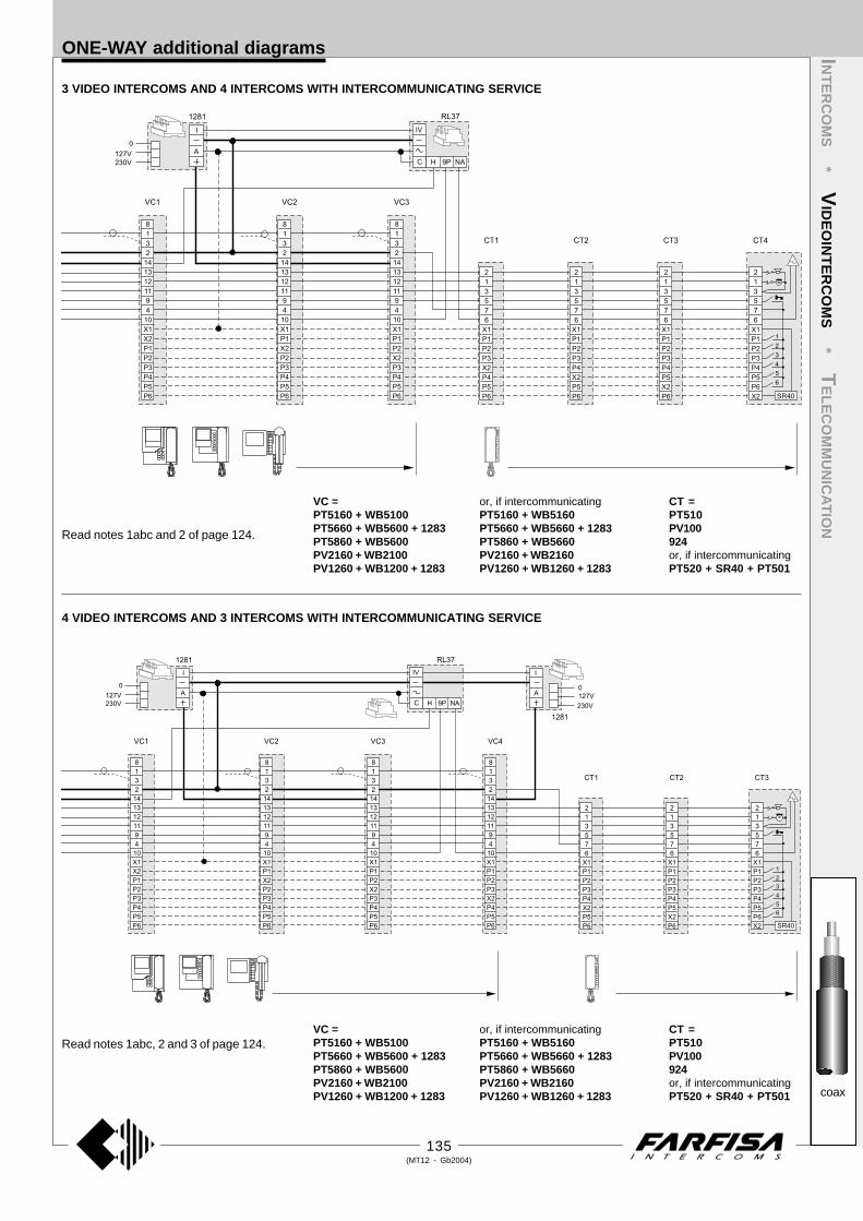
135(MT12 - Gb2004)
INT
ER
CO
MS
* VID
EO
INT
ER
CO
MS
* TE
LE
CO
MM
UN
ICA
TIO
N
coax
4 VIDEO INTERCOMS AND 3 INTERCOMS WITH INTERCOMMUNICATING SERVICE
Read notes 1abc and 2 of page 124.
Read notes 1abc, 2 and 3 of page 124.
3 VIDEO INTERCOMS AND 4 INTERCOMS WITH INTERCOMMUNICATING SERVICE
ONE-WAY additional diagrams
VC =PT5160 + WB5100PT5660 + WB5600 + 1283PT5860 + WB5600PV2160 + WB2100PV1260 + WB1200 + 1283
CT =PT510PV100924or, if intercommunicatingPT520 + SR40 + PT501
or, if intercommunicatingPT5160 + WB5160PT5660 + WB5660 + 1283PT5860 + WB5660PV2160 + WB2160PV1260 + WB1260 + 1283
VC =PT5160 + WB5100PT5660 + WB5600 + 1283PT5860 + WB5600PV2160 + WB2100PV1260 + WB1200 + 1283
CT =PT510PV100924or, if intercommunicatingPT520 + SR40 + PT501
or, if intercommunicatingPT5160 + WB5160PT5660 + WB5660 + 1283PT5860 + WB5660PV2160 + WB2160PV1260 + WB1260 + 1283

136(MT12 - Gb2004)
INT
ER
CO
MS
* VID
EO
INT
ER
CO
MS
* TE
LE
CO
MM
UN
ICA
TIO
N
coax
ONE-WAY additional diagrams
Read notes 1abc and 3 of page 124.
7 INTERCOMMUNICATING VIDEO INTERCOMS
Read notes 1abc, 2 and 3 of page 124.
5 VIDEO INTERCOMS AND 2 INTERCOMS WITH INTERCOMMUNICATING SERVICE
to terminal Iof 1382
VC =PT5160 + WB5100PT5660 + WB5600 + 1283PT5860 + WB5600PV2160 + WB2100PV1260 + WB1200 + 1283
CT =PT510PV100924or, if intercommunicatingPT520 + SR40 + PT501
or, if intercommunicatingPT5160 + WB5160PT5660 + WB5660 + 1283PT5860 + WB5660PV2160 + WB2160PV1260 + WB1260 + 1283
VC =PT5160 + WB5100PT5660 + WB5600 + 1283PT5860 + WB5600PV2160 + WB2100PV1260 + WB1200 + 1283
or, if intercommunicatingPT5160 + WB5160PT5660 + WB5660 + 1283PT5860 + WB5660PV2160 + WB2160PV1260 + WB1260 + 1283

137(MT12 - Gb2004)
INT
ER
CO
MS
* VID
EO
INT
ER
CO
MS
* TE
LE
CO
MM
UN
ICA
TIO
N
coax
MULTI-WAY additional diagrams
1 VIDEO INTERCOM AND 1 INTERCOM WITH INTERCOMMUNI-CATING SERVICE
2 INTERCOMMUNICATING VIDEO INTERCOMS
1 VIDEO INTERCOM AND 2 INTERCOMS WITH INTERCOMMU-NICATING SERVICE
2 VIDEO INTERCOMS AND 1 INTERCOM WITH INTERCOM-MUNICATING SERVICE
Read notes 1ac, 2, 4 and 5 of page 124. Read notes 1ac, 3, 4 and 5 of page 124.
Read notes 1ac, 2, 4 and 5 of page 124. Read notes 1ac, 2, 3, 4 and 5 of page 124.
D = 100V-1A diode (type 1N4007) D = 100V-1A diode (type 1N4007)
D = 100V-1A diode (type 1N4007) D = 100V-1A diode (type 1N4007)
VC =PT5160 + WB5100PT5660 + WB5600 + 1283PT5860 + WB5600PV2160 + WB2100PV1260 + WB1200 + 1283
CT =PT510PV100924or, if intercommunicatingPT520 + SR40 + PT501
or, if intercommunicatingPT5160 + WB5160PT5660 + WB5660 + 1283PT5860 + WB5660PV2160 + WB2160PV1260 + WB1260 + 1283

138(MT12 - Gb2004)
INT
ER
CO
MS
* VID
EO
INT
ER
CO
MS
* TE
LE
CO
MM
UN
ICA
TIO
N
coax
MULTI-WAY additional diagrams
1 VIDEO INTERCOM AND 3 INTERCOMS WITH INTERCOMMUNICATING SERVICE
3 INTERCOMMUNICATING VIDEO INTERCOMS
Read notes 1ac, 3, 4 and 5 of page 124.
Read notes 1ac, 2, 4 and 5 of page 124.
D = 100V-1A diode (type 1N4007)
D = 100V-1A diode (type 1N4007)
VC =PT5160 + WB5100PT5660 + WB5600 + 1283PT5860 + WB5600PV2160 + WB2100PV1260 + WB1200 + 1283
or, if intercommunicatingPT5160 + WB5160PT5660 + WB5660 + 1283PT5860 + WB5660PV2160 + WB2160PV1260 + WB1260 + 1283
VC =PT5160 + WB5100PT5660 + WB5600 + 1283PT5860 + WB5600PV2160 + WB2100PV1260 + WB1200 + 1283
CT =PT510PV100924or, if intercommunicatingPT520 + SR40 + PT501
or, if intercommunicatingPT5160 + WB5160PT5660 + WB5660 + 1283PT5860 + WB5660PV2160 + WB2160PV1260 + WB1260 + 1283

139(MT12 - Gb2004)
INT
ER
CO
MS
* VID
EO
INT
ER
CO
MS
* TE
LE
CO
MM
UN
ICA
TIO
N
coax
3 VIDEO INTERCOMS AND 1 INTERCOM WITH INTERCOMMUNICATING SERVICE
Read notes 1ac, 2, 3, 4 and 5 of page 124.
Read notes 1ac, 2, 3, 4 and 5 of page 124.
2 VIDEO INTERCOMS AND 2 INTERCOMS WITH INTERCOMMUNICATING SERVICE
MULTI-WAY additional diagrams
D = 100V-1A diode (type 1N4007)
D = 100V-1A diode (type 1N4007)VC =PT5160 + WB5100PT5660 + WB5600 + 1283PT5860 + WB5600PV2160 + WB2100PV1260 + WB1200 + 1283
CT =PT510PV100924or, if intercommunicatingPT520 + SR40 + PT501
or, if intercommunicatingPT5160 + WB5160PT5660 + WB5660 + 1283PT5860 + WB5660PV2160 + WB2160PV1260 + WB1260 + 1283
VC =PT5160 + WB5100PT5660 + WB5600 + 1283PT5860 + WB5600PV2160 + WB2100PV1260 + WB1200 + 1283
CT =PT510PV100924or, if intercommunicatingPT520 + SR40 + PT501
or, if intercommunicatingPT5160 + WB5160PT5660 + WB5660 + 1283PT5860 + WB5660PV2160 + WB2160PV1260 + WB1260 + 1283

140(MT12 - Gb2004)
INT
ER
CO
MS
* VID
EO
INT
ER
CO
MS
* TE
LE
CO
MM
UN
ICA
TIO
N
coax
MULTI-WAY additional diagrams
Read notes 1ac, 2, 4 and 5 of page 124.
1 VIDEO INTERCOM AND 4 INTERCOMS WITH INTERCOMMUNICATING SERVICE
Read notes 1ac, 2, 3, 4 and 5 of page 124.
4 INTERCOMMUNICATING VIDEO INTERCOMS
D = 100V-1A diode (type 1N4007)
D = 100V-1A diode (type 1N4007)
VC =PT5160 + WB5100PT5660 + WB5600 + 1283PT5860 + WB5600PV2160 + WB2100PV1260 + WB1200 + 1283
CT =PT510PV100924or, if intercommunicatingPT520 + SR40 + PT501
or, if intercommunicatingPT5160 + WB5160PT5660 + WB5660 + 1283PT5860 + WB5660PV2160 + WB2160PV1260 + WB1260 + 1283
VC =PT5160 + WB5100PT5660 + WB5600 + 1283PT5860 + WB5600PV2160 + WB2100PV1260 + WB1200 + 1283
or, if intercommunicatingPT5160 + WB5160PT5660 + WB5660 + 1283PT5860 + WB5660PV2160 + WB2160PV1260 + WB1260 + 1283

141(MT12 - Gb2004)
INT
ER
CO
MS
* VID
EO
INT
ER
CO
MS
* TE
LE
CO
MM
UN
ICA
TIO
N
coax
3 VIDEO INTERCOMS AND 2 INTERCOMS WITH INTERCOMMUNICATING SERVICE
Read notes 1ac, 2, 3, 4 and 5 of page 124.
Read notes 1ac, 2, 3, 4 and 5 of page 124.
2 VIDEO INTERCOMS AND 3 INTERCOMS WITH INTERCOMMUNICATING SERVICE
MULTI-WAY additional diagrams
D = 100V-1A diode (type 1N4007)
D = 100V-1A diode (type 1N4007)
VC =PT5160 + WB5100PT5660 + WB5600 + 1283PT5860 + WB5600PV2160 + WB2100PV1260 + WB1200 + 1283
CT =PT510PV100924or, if intercommunicatingPT520 + SR40 + PT501
or, if intercommunicatingPT5160 + WB5160PT5660 + WB5660 + 1283PT5860 + WB5660PV2160 + WB2160PV1260 + WB1260 + 1283
VC =PT5160 + WB5100PT5660 + WB5600 + 1283PT5860 + WB5600PV2160 + WB2100PV1260 + WB1200 + 1283
CT =PT510PV100924or, if intercommunicatingPT520 + SR40 + PT501
or, if intercommunicatingPT5160 + WB5160PT5660 + WB5660 + 1283PT5860 + WB5660PV2160 + WB2160PV1260 + WB1260 + 1283

142(MT12 - Gb2004)
INT
ER
CO
MS
* VID
EO
INT
ER
CO
MS
* TE
LE
CO
MM
UN
ICA
TIO
N
coax
MULTI-WAY additional diagrams
5 INTERCOMMUNICATING VIDEO INTERCOMS
4 VIDEO INTERCOMS AND 1 INTERCOM WITH INTERCOMMUNICATING SERVICE
Read notes 1ac, 3, 4 and 5 of page 124.
D = 100V-1A diode (type 1N4007)
Read notes 1ac, 2, 3, 4 and 5 of page 124.
D = 100V-1A diode (type 1N4007)
VC =PT5160 + WB5100PT5660 + WB5600 + 1283PT5860 + WB5600PV2160 + WB2100PV1260 + WB1200 + 1283
CT =PT510PV100924or, if intercommunicatingPT520 + SR40 + PT501
or, if intercommunicatingPT5160 + WB5160PT5660 + WB5660 + 1283PT5860 + WB5660PV2160 + WB2160PV1260 + WB1260 + 1283
VC =PT5160 + WB5100PT5660 + WB5600 + 1283PT5860 + WB5600PV2160 + WB2100PV1260 + WB1200 + 1283
or, if intercommunicatingPT5160 + WB5160PT5660 + WB5660 + 1283PT5860 + WB5660PV2160 + WB2160PV1260 + WB1260 + 1283

143(MT12 - Gb2004)
INT
ER
CO
MS
* VID
EO
INT
ER
CO
MS
* TE
LE
CO
MM
UN
ICA
TIO
N
coax
2 VIDEO INTERCOMS AND 4 INTERCOMS WITH INTERCOMMUNICATING SERVICE
Read notes 1ac, 2, 4 and 5 of page 124.
Read notes 1ac, 2, 3, 4 and 5 of page 124.
1 VIDEO INTERCOM AND 5 INTERCOMS WITH INTERCOMMUNICATING SERVICE
MULTI-WAY additional diagrams
D = 100V-1A diode (type 1N4007)
D = 100V-1A diode (type 1N4007)
VC =PT5160 + WB5100PT5660 + WB5600 + 1283PT5860 + WB5600PV2160 + WB2100PV1260 + WB1200 + 1283
CT =PT510PV100924or, if intercommunicatingPT520 + SR40 + PT501
or, if intercommunicatingPT5160 + WB5160PT5660 + WB5660 + 1283PT5860 + WB5660PV2160 + WB2160PV1260 + WB1260 + 1283
VC =PT5160 + WB5100PT5660 + WB5600 + 1283PT5860 + WB5600PV2160 + WB2100PV1260 + WB1200 + 1283
CT =PT510PV100924or, if intercommunicatingPT520 + SR40 + PT501
or, if intercommunicatingPT5160 + WB5160PT5660 + WB5660 + 1283PT5860 + WB5660PV2160 + WB2160PV1260 + WB1260 + 1283

144(MT12 - Gb2004)
INT
ER
CO
MS
* VID
EO
INT
ER
CO
MS
* TE
LE
CO
MM
UN
ICA
TIO
N
coax
MULTI-WAY additional diagrams
4 VIDEO INTERCOMS AND 2 INTERCOMS WITH INTERCOMMUNICATING SERVICE
3 VIDEO INTERCOMS AND 3 INTERCOMS WITH INTERCOMMUNICATING SERVICE
Read notes 1ac, 2, 3, 4 and 5 of page 124.
D = 100V-1A diode (type 1N4007)
Read notes 1ac, 2, 3, 4 and 5 of page 124.
D = 100V-1A diode (type 1N4007)
VC =PT5160 + WB5100PT5660 + WB5600 + 1283PT5860 + WB5600PV2160 + WB2100PV1260 + WB1200 + 1283
CT =PT510PV100924or, if intercommunicatingPT520 + SR40 + PT501
or, if intercommunicatingPT5160 + WB5160PT5660 + WB5660 + 1283PT5860 + WB5660PV2160 + WB2160PV1260 + WB1260 + 1283
VC =PT5160 + WB5100PT5660 + WB5600 + 1283PT5860 + WB5600PV2160 + WB2100PV1260 + WB1200 + 1283
CT =PT510PV100924or, if intercommunicatingPT520 + SR40 + PT501
or, if intercommunicatingPT5160 + WB5160PT5660 + WB5660 + 1283PT5860 + WB5660PV2160 + WB2160PV1260 + WB1260 + 1283

145(MT12 - Gb2004)
INT
ER
CO
MS
* VID
EO
INT
ER
CO
MS
* TE
LE
CO
MM
UN
ICA
TIO
N
coax
6 INTERCOMMUNICATING VIDEO INTERCOMS
Read notes 1ac, 2, 3, 4 and 5 of page 124.
5 VIDEO INTERCOMS AND 1 INTERCOM WITH INTERCOMMUNICATING SERVICE
MULTI-WAY additional diagrams
Read notes 1ac, 2, 3, 4 and 5 of page 124.
D = 100V-1A diode (type 1N4007)
D = 100V-1A diode (type 1N4007)
VC =PT5160 + WB5100PT5660 + WB5600 + 1283PT5860 + WB5600PV2160 + WB2100PV1260 + WB1200 + 1283
CT =PT510PV100924or, if intercommunicatingPT520 + SR40 + PT501
or, if intercommunicatingPT5160 + WB5160PT5660 + WB5660 + 1283PT5860 + WB5660PV2160 + WB2160PV1260 + WB1260 + 1283
VC =PT5160 + WB5100PT5660 + WB5600 + 1283PT5860 + WB5600PV2160 + WB2100PV1260 + WB1200 + 1283
or, if intercommunicatingPT5160 + WB5160PT5660 + WB5660 + 1283PT5860 + WB5660PV2160 + WB2160PV1260 + WB1260 + 1283

146(MT12 - Gb2004)
INT
ER
CO
MS
* VID
EO
INT
ER
CO
MS
* TE
LE
CO
MM
UN
ICA
TIO
N
coax
MULTI-WAY additional diagrams
Read notes 1ac, 2, 3 and 5 of page 124.
2 VIDEO INTERCOMS AND 5 INTERCOMS WITH INTERCOMMUNICATING SERVICE
Read notes 1ac, 2 and 5 of page 124.
1 VIDEO INTERCOM AND 6 INTERCOMS WITH INTERCOMMUNICATING SERVICE
D = 100V-1A diode (type 1N4007)
D = 100V-1A diode (type 1N4007)VC =PT5160 + WB5100PT5660 + WB5600 + 1283PT5860 + WB5600PV2160 + WB2100PV1260 + WB1200 + 1283
CT =PT510PV100924or, if intercommunicatingPT520 + SR40 + PT501
or, if intercommunicatingPT5160 + WB5160PT5660 + WB5660 + 1283PT5860 + WB5660PV2160 + WB2160PV1260 + WB1260 + 1283
VC =PT5160 + WB5100PT5660 + WB5600 + 1283PT5860 + WB5600PV2160 + WB2100PV1260 + WB1200 + 1283
CT =PT510PV100924or, if intercommunicatingPT520 + SR40 + PT501
or, if intercommunicatingPT5160 + WB5160PT5660 + WB5660 + 1283PT5860 + WB5660PV2160 + WB2160PV1260 + WB1260 + 1283

147(MT12 - Gb2004)
INT
ER
CO
MS
* VID
EO
INT
ER
CO
MS
* TE
LE
CO
MM
UN
ICA
TIO
N
coax
4 VIDEO INTERCOMS AND 3 INTERCOMS WITH INTERCOMMUNICATING SERVICE
Read notes 1ac, 2, 3 and 5 of page 124.
3 VIDEO INTERCOMS AND 4 INTERCOMS WITH INTERCOMMUNICATING SERVICE
MULTI-WAY additional diagrams
Read notes 1ac, 2, 3 and 5 of page 124.
D = 100V-1A diode (type 1N4007)
D = 100V-1A diode (type 1N4007)
VC =PT5160 + WB5100PT5660 + WB5600 + 1283PT5860 + WB5600PV2160 + WB2100PV1260 + WB1200 + 1283
CT =PT510PV100924or, if intercommunicatingPT520 + SR40 + PT501
or, if intercommunicatingPT5160 + WB5160PT5660 + WB5660 + 1283PT5860 + WB5660PV2160 + WB2160PV1260 + WB1260 + 1283
VC =PT5160 + WB5100PT5660 + WB5600 + 1283PT5860 + WB5600PV2160 + WB2100PV1260 + WB1200 + 1283
CT =PT510PV100924or, if intercommunicatingPT520 + SR40 + PT501
or, if intercommunicatingPT5160 + WB5160PT5660 + WB5660 + 1283PT5860 + WB5660PV2160 + WB2160PV1260 + WB1260 + 1283

148(MT12 - Gb2004)
INT
ER
CO
MS
* VID
EO
INT
ER
CO
MS
* TE
LE
CO
MM
UN
ICA
TIO
N
coax
7 INTERCOMMUNICATING VIDEO INTERCOMS
Read notes 1ac, 2, 3 and 5 of page 124.
Read notes 1ac, 3 and 5 of page 124.
5 VIDEO INTERCOMS AND 2 INTERCOMS WITH INTERCOMMUNICATING SERVICE
MULTI-WAY additional diagrams
VC =PT5160 + WB5100PT5660 + WB5600 + 1283PT5860 + WB5600PV2160 + WB2100PV1260 + WB1200 + 1283
VC =PT5160 + WB5100PT5660 + WB5600 + 1283PT5860 + WB5600PV2160 + WB2100PV1260 + WB1200 + 1283
CT =PT510PV100924or, if intercommunicatingPT520 + SR40 + PT501
or, if intercommunicatingPT5160 + WB5160PT5660 + WB5660 + 1283PT5860 + WB5660PV2160 + WB2160PV1260 + WB1260 + 1283
or, if intercommunicatingPT5160 + WB5160PT5660 + WB5660 + 1283PT5860 + WB5660PV2160 + WB2160PV1260 + WB1260 + 1283
D = 100V-1A diode (type 1N4007)
D = 100V-1A diode (type 1N4007)

149(MT12 - Gb2004)
TELECOMMUNICATIONTechnical manual 12 Edition 2004
INDEX
Internal stations
-Telephone
-Studio series monitors
-Studio series video and intercom-telephone set
-Video memory
Intercom-telephone interface
Telephone protections
PABX
Installation instructions
- Intercom-telephone systems
-Video intercom-telephone systems
-Video signal distribution with twisted pair (balanced line)
-Conversion of video signal from coaxial cable to balanced line
Basic installation diagrams
- Si 111T/1 One way intercom-telephone system with telephone interface and connection to one external door station
- Si 111T/2 One-way intercom-telephone intercommunicating system with PABX and connection to one external door station
- Si 11MT/1 Mixed intercom/telephone system connected to one external door station
- Si 311T/1 One-way video intercom-telephone system with telephone interface and connection to one external door station (with
coaxial cable)
- Si 311T/2 One-way video intercom-telephone system with PABX and connection to one external door station (with coaxial cable)
- Si 311T/3 One-way video intercom-telephone system with telephone interface and connection to one external door station (with
twisted pair)
- Si 311T/7 One-way video intercom-telephone system with PABX and connection to one external door station (with twisted pair)
- Si 31MT/1 Mixed video intercom/video intercom-telephone system connected to one external door station (with coaxial cable)
- Si 31MT/2 Video intercom-telephone system connected to one external door station (with twisted pair)
- Si 32MT/1 Video intercom-telephone system connected to two external door stations (with twisted pair)
- Si 312T/1 Two-way video intercom-telephone intercommunicating system with PABX connected to one external door station (with
coaxial cable)
- Si 312T/2 Two-way video intercom-telephone intercommunicating system with PABX connected to one external door station (with
twisted pair)
Video intercom-telephone additional diagrams
- for video intercom system with coaxial cable
- for video intercom system with twisted pair
Product list
Page
150
150
154
157
160
162
163
164
170
170
170
171
172
173
173
173
175
176
176
177
177
179
181
183
185
187
188
188
190
192
The main intercom and video intercom functions can also be provided with an ordinary telephone set by installing a suitable interface in the intercomsystem.For better intercom/telephone integration it is advisable to use the dedicated Farfisa telephone art. ST740W. In addition to the normal telephonefunctions, this telephone has extra buttons for intuitive and easy use of intercom functions.

150(MT12 - Gb2004)
INTERNAL STATIONSINT
ER
CO
MS
* VID
EO
INT
ER
CO
MS
* TE
LE
CO
MM
UN
ICA
TIO
N
STUDIO
Connect the telephone cable sup-plied with the product to the plug onthe back of the telephone.
TELEPHONE
ST740W. White telephone for intercom or video intercom-telephonesystems. Complete with spiral cord, electronic microphone, 15 buttonsfor telephone functions, 7 buttons for intercom functions and directmemories. The buttons dedicated to intercom functions can operateonly by means of a suitable telephone interface (FT11D) or PABX(FT105P or FT208P).The telephone permits DTMF dialling only.Wall mounting with bracket WB700 or table version with adapter TA700and bracket WB700.
2 "8/
5
67
3 "16/
11
93
8 "4/
1
209
Door-opener button
Button for stair lights acti-vation or other services
Button for communicationwith external door station
Memory buttons
Keypad
Key R or FLASHProgramming keyRepeat key
Ringing volume adjustment
Description
WB 700. Bracket for fixing on wall or to tableadapter (with art.TA700) the ST740 telephoneand/or accessories of the Studio series.Complete with plastic templates for the cor-rect alignment with bracket WB 7100 and/orother brackets WB700.
NoteThe flat cable supplied with the bracket can-not be used in telephone systems.
FIXING ELEMENTS
3 "16/5
83.5
Wall version
INSTALLATION
The telephone can be installed on the wall or on the table with dedicatedaccessories.
Fix the bracket WB700 to a back box or to thewall with 2 expansion plugs.
TA 700W. White table adapter for telephoneST740W and/or accessories of the Studioseries.Complete with cable clamp, plastic and me-tallic frames for the correct alignment to adapt-ers TA7100 and/or additional TA700.

151(MT12 - Gb2004)
INTERNAL STATIONS INT
ER
CO
MS
* VID
EO
INT
ER
CO
MS
* TE
LE
CO
MM
UN
ICA
TIO
N
STUDIO
Hook the telephone to the bracket.
Unhook the telephone from the bracket.
Connect the 2 wires of the cable to terminalsDER41÷45/48 of the PABX (FT105P orFT208P) or L+ and L- of the telephone inter-face FT11D.
Table version
Apply the 4 anti-slip rubber pads in theirhousings under the table adapter base.
Make the hole for the telephone cable.
Block the telephone cable to the table adapterwith the cable clamp.
Fix the WB700 bracket to the table adapterwith the 2 screws supplied.
Hook the telephone to the adapter.
Connect the telephone cable to the plug on theback of the telephone.

152(MT12 - Gb2004)
PROGRAMMING
The ST740W has been developed for exclusive use with FarfisaPABX’s or telephone interface. It is programmed for use with FT105Pand FT208P PABX by default. The default setting can be modified asdescribed below in this manual.
Default setting
Button Code Function
6R1 activation of relay 1 of FT105P and FT208PPABX
6R2 activation of relay 2 of FT105P and FT208PPABX
6 audio connection with external door station con-nected to FT105P and FT208P PABX
R 1 timing of R key equal to 90 msec
The ringing volume is set at the maximum value.
How to program the timing of R (FLASH) key
To change programming:-pick-up the handset-press ; no tone is heard on the loudspeaker-press R- press 1 or 2 (90 or 330msec, respectively)- press ; if programming is correct, you hear the actual tone of thePABX. If not, you hear a continuous sharp tone to indicate incorrectprogramming.
Note: in case of error replace the handset and repeat the program-ming procedure.
INTERNAL STATIONSINT
ER
CO
MS
* VID
EO
INT
ER
CO
MS
* TE
LE
CO
MM
UN
ICA
TIO
N
STUDIO
How to program the buttons , ,
The buttons can change their function by changing programming asdesired. They can be used to:- enable PABX short numbers-enable audio and door opening in installations with FT11D interface-change operation mode of relay (i.e. for two-way installations withdifferentiated door locks, activation of relays 3 and 4, etc.). See thePABX instructions on pages 168 and 169.
To change programming:-pick-up the handset-press ; no tone is heard on the loudspeaker
-press the button you want to program ( , or )- dial the new code on the keypad (see table)- press ; if programming is correct, you hear the actual tone of PABX.If not, you hear a continuous sharp tone to indicate incorrect program-ming.
Note: in case of error replace the handset and repeat the program-ming procedure.
Table of programmable functions for the buttons , ,
Code Function
6R1 activation of relay 1 of ES60 or ES65 intercom interface withFT105P and FT208P PABX's
6R2 activation of relay 2 of ES60 or ES65 intercom interface withFT105P and FT208P PABX's
6R3 simultaneous activation of relays 1 and 2 of ES60 or ES65intercom interface with FT105P and FT208P PABX's
7832 activation of relay 3 of ES65 intercom interface with FT105Pand FT208P PABX's
7842 activation of relay 4 of ES65 intercom interface with FT105Pand FT208P PABX's
6 audio connection with external door station with ES60 orES65 intercom interface and FT105P or FT208P PABX's
RRRR door opening with FT11D telephone interface
RR audio connection with external door station with FT11Dtelephone interface
Apart from the codes in the table, you can program numbers or functions(*, #, R, RP) for a max. of 6 digits (short numbers, emergency numbers,numbers of special services offered by the telephone provider, etc.). TheRP key inserts a 3-sec. pause in the numerical sequence to be pro-grammed.
(90msec)
(330msec)

153(MT12 - Gb2004)
INTERNAL STATIONS INT
ER
CO
MS
* VID
EO
INT
ER
CO
MS
* TE
LE
CO
MM
UN
ICA
TIO
N
STUDIO
How to program the M3, M4, M5 and M6 memorybuttonsYou can use these buttons to program frequently used numbers.
To program the buttons:- pick-up the handset-press ; no tone is heard on the loudspeaker-press the button you want to program (M3, M4, M5 or M6)- dial the number on the keypad (max. 24 digits)- press ; if programming is correct, you hear the actual tone of PABX.If not, you hear a continuous sharp tone to indicate incorrect program-ming.
Note: in case of error replace the handset and repeat the program-ming procedure.
Important:- if the telephone is connected to the FT105P or FT208P PABX’s, youmust dial 0, 81 or 82 before telephone number of the user to access theexternal line (i.e. 810548975615); in case of international calls, it isrecommended to insert a pause (by pressing RP) between theinternational code and the user number (i.e. 81001RP67859063).
- if the telephone is connected to the FT11D interface you can programthe telephone number directly; in case of international numbers it isrecommended to insert a pause (i.e.001RP678599063).
Answer a callPick-up the handset.Replace the handset after conversation.
Make a callPick-up the handset.Dial the number.Replace the handset after conversation.
Note. If the telephone is connected to a Farfisa PABX's, you must dial0, 81 or 82 to access the external line.
Redial of the last call number dialledPick-up the handset.Press RP.Replace the handset after conversation.
Note. The key RP redials the last call number dialled only if it is the firstbutton you press after picking-up the handset. If not, this key inserts a3-sec. pause during dialling.
Intercom function buttonsThese functions can be used only if an intercom installation is con-nected to the PABX or telephone interface.
Pick-up the handset.Press:
to operate the electric door lock
to activate stair light or other service
to enable intercom conversation
Replace the handset.
Note. When using the FT11D telephone interface you must programproperly the buttons and for correct operations wait for the publicexchanger tone before using them.
Memory buttonsThese buttons need to be programmed.
Pick-up the handset.Press the button associated to the telephone number you want to dial(M3, M4, M5 or M6).Replace the handset after conversation.
Ringing volume adjustmentMove the switch located on the bottom of the telephone on the desiredposition (OFF, min. and max.).
PROGRAMMING
OFF MIN. MAX.
OPERATION

154(MT12 - Gb2004)
INTERNAL STATIONSINT
ER
CO
MS
* VID
EO
INT
ER
CO
MS
* TE
LE
CO
MM
UN
ICA
TIO
N
STUDIO
8 "16/
13
224
2 "8/
3
616 "
8/1
156
VIDEO INTERCOM-TELEPHONE SET
ST 7100W. White monitor with flat CRT and 2buttons. One button for control switch ON andone button for supplementary services. Maxi-mum acceptable current of buttons is 0.3A. Forhigher currents use relay art. 1471 or 1472.The monitor can be surface mounted on thewall with bracket art. WB7100.
Technical dataPower supply 18÷24VdcOperating current 0.35AMonitor 4" FLAT CRTTV standard CCIR-625 linesHorizontal frequency 15625HzVertical frequency 50HzBandwidth >5MHzVideo signal on 75Ω 0.8÷1.5VppStarting up time 2÷4 sec.Operating temperature 0°÷+50°CMax. permissible humidity 90%RH
ST 7100CW. Version with colour LCD ofmonitor ST7100W.
Technical dataPower supply 18÷24VdcOperating current 0.4AMonitor 4" LCDTV standard PALHorizontal frequency 15625HzVertical frequency 50HzBandwidth >5MHzVideo signal on 75Ω 0.8÷1.5VppStarting up time 1 sec.Operating temperature 0°÷+50°CMax. permissible humidity 90%RH
Choosing the video connection with co-axial cable or twisted pair
With monitor ST7100 the video connection canbe made either with 75 Ohm coaxial cable ortwisted pair. The choice between the two sys-tems depends on the correct selection of videodistributor and camera. The number of wiresand possible installations does not change. Donot forget to position jumper J2 correctlyand use the proper input terminals ofbracket WB7100.
A = Video connection with coaxialcable at terminals V and M
B =Video connection with twisted pairat terminals X and Y
NoteThe bracket is also equipped with connectorJ1. This connector shall not be used in videointercom-telephone systems.
To realise a video intercom-telephone systemyou must combine the ST740 telephone withbracket WB700 to a monitor ST7100 (orST7100C) and bracket WB7100.
MONITORS
TA 7100W. White Table adapter for ST7100Wand ST7100CW monitors. Complete with cableclamp, junction box and 2.4m connection cablewith 20 wires.
FIXING ELEMENTS for Studio se-ries.
WB 7100. The bracket allows for wall-fixing ofmonitor ST7100. Complete with terminal boardfor connection to the system and connectors forconnection to the monitor. One or more brack-ets WB 700 can be used to expand the system.
TerminalsV Video signal input 0.8÷1.5VppM Video groundF General groundH Positive power supply input 18÷24VdcX Negative balanced video signal inputY Positive balanced video signal input1, 2, 3, 5 Not used.4 Control switching ON – button 8 Positive power supply output for video dis-
tributors 12Vdc9M Call input from external door station (250mA)9R Intercommunicating or floor-call input9V Activation input for FN4000 digital systems
(ground command)1C Common of button for control switching ONPC Common of service buttonP Service button (symbol )

155(MT12 - Gb2004)
The video intercom-telephone system can be also realized by separat-ing the intercom/telephone function from the video function. For ex-ample: install the monitor on the wall and use a standard or cordlesstelephone to answer to intercom/telephone calls.
INTERNAL STATIONS
2) Make the connections on the bracket terminal board.
JP1
J2JP3 JP4
H
1
2
3
9V
9R
9M
5
F
4Y X P P 8 1C CV
M
VR9
JP
5
J1
JP
2
1 2 3
1
14
U1
1
10
3
2
1
aaaaaaaaaaaaaaaaaaaaaaaaaaaa
4 ' 13"
JP1
J2
H
1
2
3
9V
9R
9M
5
F
4Y X P P 8 1C CV
M
VR9
J1
JP
2
1 2 3
1
14
U1
1
10
3
2
1
1) Fix the bracket WB7100 to the wall with the 3fixing points at approximately 1.55 m (4' 13")distance from the floor to the upper part of thebracket.
MONITOR ONLY
Installation steps for monitor ST7100 or ST 7100C in wall or tableversion.
INT
ER
CO
MS
* VID
EO
INT
ER
CO
MS
* TE
LE
CO
MM
UN
ICA
TIO
N
STUDIO
3) Connect the monitor cable to thebracket.
4) Hook the monitor to the bracket.
JP1
J2JP4
H
1
2
3
9V
9R
9M
5
F
4Y X P P 8 1C CV
M
R9
JP
5
J1
JP
2
1 2 3
1
14
U1
1
10
3
2
1
U
P
U
P
Wall version

156(MT12 - Gb2004)
Table version
1) Apply the 4 anti-slip rubber pads in their housing under the tableadapter base.
5) Mark the colour/terminal combinationon the junction box.
JP1
J2JP4
H
1
2
3
9V
9R
9M
5
F
4Y X P P 8 1C CV
M
R9
JP
5J1
JP
2
1 2 3
1
14
U1
1
10
3
2
1
U
P
U
P
3) Fix the bracket WB7100 with the 2screws supplied.
4) Make the connection to the bracketterminal board according to the in-stallation diagram.
2) Pass the connection cable through thehole on the back of the table adapterand block it with the cable clamp.
6) Connect the monitor cable to thebracket.
7) Hook the monitor to the bracket.
INTERNAL STATIONSINT
ER
CO
MS
* VID
EO
INT
ER
CO
MS
* TE
LE
CO
MM
UN
ICA
TIO
N
STUDIO

157(MT12 - Gb2004)
JP1
J2JP3 JP4
H
1
2
3
9V
9R
9M
5
F
4Y X P P 8 1C CV
M
VR9
JP
5
J1
JP
2
1 2 3
1
14
U1
1
10
3
2
1
1) Before fixing the bracket WB700, position the 2 plastic templates onthe holes of bracket WB7100.
JP1
J2
J1
JP
2
1 2 3
3
2
1
2) Fix the 2 brackets to the wall according to the instructions of figure 1on page 155.
Installation steps for monitor ST7100W (or ST7100CW), telephoneST740W, brackets WB7100 and WB700 and table adapters (if neces-sary) to obtain an internal station with video intercom-telephone func-tions.
Wall version
4) Pass the telephone cable throughthe space between the telephone andthe bracket. Pull the cable in such away that the extra part of the cablefaces the monitor bracket.
Note.If necessary, to make it easier to pass thecable between the telephone and moni-tor, you can use the breaking points onthe base of telephone and monitor (onlythe sides that are interested by the pas-sage of the cable).
3) Connect the telephone cable sup-plied with the product to the plug on theback of the telephone.
VIDEO INTERCOM-TELEPHONE SET
9 "16/
13
249
8 "16/
13
224
2 "8/
5
67
INTERNAL STATIONS INT
ER
CO
MS
* VID
EO
INT
ER
CO
MS
* TE
LE
CO
MM
UN
ICA
TIO
N
STUDIO

158(MT12 - Gb2004)
7) Connect the monitor cable tothe bracket.
6)Make the connections on the terminal board of bracket WB7100according to the installation diagram.
5) Hook the telephone to the bracket WB700.
INT
ER
CO
MS
* VID
EO
INT
ER
CO
MS
* TE
LE
CO
MM
UN
ICA
TIO
N
INTERNAL STATIONS
STUDIO
JP1
J2
H
1
2
3
9V
9R
9M
5
F
4Y X P P 8 1C CV
M
VR9
J1
JP
2
1 2 3
1
14
U1
1
10
3
2
1
10
8) Hook the monitor to the bracket.
JP1
J2JP4
H
1
2
3
9V
9R
9M
5
F
4Y X P P 8 1C CV
M
R9
JP
5
J1
JP
2
1 2 3
1
14
U1
1
10
3
2
1
U
P
U
P

159(MT12 - Gb2004)
INTERNAL STATIONS INT
ER
CO
M * V
IDE
O IN
TE
RC
OM
* TE
LE
CO
MM
UN
ICA
TIO
N
STUDIO
6) Screw brackets WB7100 and WB700 to the table adapters.
Table version
7) Apply the monitor and telephone according tothe instructions on pages 157 and 158 (frompoint 3 to 8).When connecting the wires to the terminalboards of bracket WB7100 (point 6) you mustmark the colour/terminal combination on thejunction box.
1) Apply the 8 anti-slip rubber pads in their housings under the base ofthe table adapters TA7100 and TA700.
2) Pass the connection cable through thehole in the back of the table adapterTA7100 and block it with the cableclamp.
3) The arrow indicate the breaking points for the application of themetallic frames (a) and the passage of the telephone cable (b).
aa
a
b
4) Screw the 2 metallic frames to the table adapter TA7100 and hookthe plastic frame to them (c).
c
5) Screw the table adapter TA700 to the 2 metallic frames.

160(MT12 - Gb2004)
INT
ER
CO
MS
* VID
EO
INT
ER
CO
MS
* TE
LE
CO
MM
UN
ICA
TIO
N
INTERNAL STATIONS
STUDIO
Wall version
VIDEO INTERCOM-TELEPHONE WITH VIDEO MEMORY
ST7M32W. Video memory.For information on connections and specifications see the instructionsmanual supplied with the product. The only difference between videointercom and video intercom-telephone connections is represented bythe fact that in video intercom-telephone systems the 4 main functions ofthe video memory can not be remotely actuated with the telephonebecause it is not provided with buttons for these functions.
InstallationInstallation steps for the realisation of one video intercom-telephoneinternal station with video memory in wall or table version.
For this composition you need:1 ST7100 or ST7100C (monitor)1 ST740 (telephone)1 ST7M32 (video memory)1 WB7100 (bracket for monitor)2 WB700 (brackets for telephone and video memory)
For the table version you must add:1 TA7100 (table adapter for monitor)2 TA700 (table adapter for telephone and video memory)
To install a video memory module next to the monitor and telephone, youmust insert the 2 plastic templates contained in the packing on theproper holes of the bracket WB700 before fixing it.
2 "8/
5
6713 "
16/7
342
8 "16/
13
224
JP1
J2JP3 JP4
H
1
2
3
9V
9R
9M
5
F
4Y X P P 8 1C CV
M
VR9
JP
5
J1
JP
2
1 2 3
1
14
U1
1
10
3
2
1
1) Before fixing the second bracket WB700, position the 2 plastictemplates on the bracket holes.
JP1
J2JP3 JP4
H
1
2
3
9V
9R
9M
5
F
4Y X P P 8 1C CV
M
VR9
JP
5
J1
JP
2
1 2 3
1
14
U1
1
10
3
2
1
2) Fix the third bracket to the wall.
3) Hook the monitor and telephone according to the instructions onpages 157 and 158 from point 3 to 8.
XI YI VI M M VOYOXO
DV 8 F F D R A P 5) Remove the flat cablethat connects the 2boards.
7) Make the connection as shown in the installation diagram, reconnectthe internal flat cable and replace the cover at the base of the videomemory.
XI YI VI M M VOYOXO
DV 8 F F D R A P
6) Pass the connection wires through thehole on the base and hook the base tothe bracket.
4) Remove the video memory cover bydisengaging it from the bottom part.

161(MT12 - Gb2004)
INTERNAL STATIONS INT
ER
CO
MS
* VID
EO
INT
ER
CO
MS
* TE
LE
CO
MM
UN
ICA
TIO
N
STUDIO
Table version
2) Pass the connection cable through thehole on the back of the table adapterTA7100 and block it with the cableclamp supplied.
3) The arrows indicate the breaking points for the application of themetallic frames (a) and for the video memory wires (b).
a
a
b
a
a
b
5) Screw the brackets WB7100 and WB700 on the table adapters.
4) Screw the 4 metallic frames on the table adapters and hook the 2plastic frames to them (see drawing 4 on page 159).
6) Hook the monitor and intercom according to the instructions onpages 157 and 158 (point 3 to 8) and the video memory according tothe instructions on page 160 (point 4 to 7).When connecting the wires on the terminal boards of bracket WB7100(point 6), mark the colour/terminal combination on the junction box.
1) Apply the 12 anti-slip rubber pads supplied intheir housing under the base of the table adapt-ers TA7100 e TA700.

162(MT12 - Gb2004)
Telephone and electrical connections
- Connect the two wires of the trunk line (tele-phone pair) to terminals TIP and RING.
- Connect the two wires of the telephone toterminals L- and L+ (telephone pair). The maxi-mum distance between the interface and thelast telephone is 350m with 0.6mm² pair. Donot lay the telephone cables together withelectrical cables.
- Connect the five wires of the intercom systemto terminals 1, 2, 3, 5 and 6.
- Connect the two wires of the electrical mainsto terminals 0 and 230 (or 0-127 according tothe ratings of the mains). It is necessary toprovide a disconnecting and safety bipo-lar switch before the device.
- Insert the 2 plastic protection of the terminalcovers supplied with the product.
FT11D. Intercom-telephone interface.It allows the connection of the trunk line and theintercom system to home telephone.
Technical dataPower supply 127/230VacMaximum power consumption 7VAFlashing time (button “R”) 80 ÷ 330msecRinging Voltage 48Vac - 15mAOperating temperature 0° ÷ +40°CMaximum humidity 85% RHHousing DIN 8 modules A
NoteThe model is not provided with fuses, but it isprotected against overloading or short-circuit-ing by temperature sensors (thermoprotector).In order to reset them, it is necessary to cut offthe mains voltage for about one minute. Recon-nect power after correcting the fault.
TerminalsTip/ Ring trunk line connectionL-/ L+ telephone connection0/ 127 input voltage 127Vac0/ 230 input voltage 230Vac1 audio transmission2 audio receiver3 ground4 terminal connected to ground. It can be iso-
lated by cutting W5 jumper. The normallyopen contact of relay, is connected betweenterminals 4 and 5.
5 lock release - max 1A (common relay con-tact)
6 intercom call input (12Vac - 150 mA)7 normally closed contact of relay
INSTALLATION
The intercom-telephone interface FT11D inDIN housing 8 modules A can be installed insuitable electrical box provided with bar sup-port in compliance with DIN 46277 standards.It can also be fixed to the wall with two screwsand expansion plugs not supplied with the prod-uct. The two plastic protections of the ter-minal boards must be mounted in case ofwall installation. They can be eliminated incase of installation on DIN bar in electrical box.
PROGRAMMING THE TELEPHONEST740WBoth a standard telephone and model ST740can be used as internal extension.When using art.ST740 it is necessary to pro-gram it in order to use the buttons dedicated tointercom functions. For information on pro-gramming see page 152. Following are thecodes that can be assigned to the intercombuttons.
Button CodeRRRRRR
can be programmed with a maxi-mum number of 6 digits (emer-gency number, telephone providerspecial services).
OPERATION AND USEDo not open or tamper with the devicesince it contains high voltages inside. In-stallation and maintenance must be donneexclusively by specialized personnel.
Please consider that also if the telephone inter-face is ON for outgoing / incoming calls thetelephone is connected to the trunk line directly.To operate the telephone inteface set the switchon “I”.A flashing indicator (LED) shows the system isworking properly.
Incoming outside calls- When receiving a call from the trunk line it isenough to pick up the handset and to answer.
Outgoing external calls- Pick up the handset.- Wait for the dial tone of public exchanger.- Dial the number.
Intercom connection without an outdoorincoming call- Pick up the handset.- Wait for the dial tone of public exchanger.(ST740) - press
(Standard) - the “R” key twice (R+R) in a 3-seconds lapse of time.
INTERCOM-TELEPHONE INTERFACEINT
ER
CO
MS
* VID
EO
INT
ER
CO
MS
* TE
LE
CO
MM
UN
ICA
TIO
N
FARTEL
3 "2/
1
89
2 "16/
15
74
5 "2/
1
140
Trunk line

163(MT12 - Gb2004)
Signalling table
Intercom call / call back ringing tone
Warning tone
Intercom callAn intercom call is signalled on the telephonewith a faster ringing tone than a conventionalincoming outside call. The telephone is auto-matically connected to the intercom line, toanswer it is enough to pick up the handset.If within 25 seconds you don’t answer, thetelephone is connected again to the trunk line.
Door-openerWhen the telephone is connected to the exter-nal door intercom station, the user can open thedoor by pressing:(ST740) - the button(Standard) - the “R” key twice (R+R) in a 3-
seconds lapse of time.
Intercom call during a telephone conver-sationDuring a telephone conversation, an acousticsignal (beep) indicates the intercom call.The user can:-answer the intercom call and put the tele-phone conversation on hold (music on hold)by pressing:
(ST740) - the button(Standard) - the “R” key twice (R+R) in a 3-
seconds lapse of time.To retrieve the telephone conversation the usermust replace the handset and wait for the tele-phone ringing back;- answer to the intercom call and clear the
telephone call by replacing the handset andwaiting for the incoming intercom call to ring;
- ignore the intercom call and continue thetelephone call. The intercom call remainsactive for 25 seconds, while the beep signalremains active only for 10 seconds.
Phone call during an intercom conversa-tionDuring an intercom conversation, any phonecall is signalled by a bip on the background. Inorder to answer the phone call, the user has toreplace the handset and wait for the incomingoutside call.
EmergencyIn case of power failure, the telephone is con-nected directly to the trunk line.
TELEPHONE PROTECTIONS
PR1. Protection for 1 telephone line.PR2. Protection for 2 telephone lines.PRAL. Protection for electrical line (230Vac).
WARNINGSDo not install the protections in humid places ornear heat sources.Do not introduce objects or pour liquids insidethe protections.Do not install the protections during a storm.Do not touch non-insulated cables, unless theyare not disconnected from the mains.The protections do not contain user-serviceableparts: do not open the protection housings. Ifnecessary, contact an authorized service cen-tre.
MECHANICAL ASSEMBLINGFor the mechanical assembling use the fasteningmeans supplied with the kit.The protection devices can be assembled on G-type (EN 50035) and OMEGA-type (EN 50022)DIN bars.
Assembling on OMEGA bar
1 Ground spring2 Fixing screw3 Notched washer Ø54 Plastic fastener5 Omega bar
Note: Only use the plastic fastener in case ofassembling on OMEGA bar without ground con-nection.
Assembling on G bar
1 Fixing screw2 Split washer Ø43 Flat washer Ø44 Notched washer Ø45 Omega bar6 Mechanical fastener and ground terminal
ELECTRICAL ASSEMBLINGThe protection device must be connected to theground system using the terminals provided and/or the grounded DIN bar. The lower the resistanceof the ground system, the higher the efficacy of theprotection device. Disconnect the power supplybefore making the connections and refer to thewiring diagrams.
INSTALLATION DIAGRAMS
PR1 PR2Trunkline
Trunklines
Apparatus
SERIES connection for monophase powersupply
PARALLEL connection for monophase powersupplyConnect the protection device in parallel to pre-vent it from being crossed by the operating cur-rent. This allows for connecting devices that ab-sorb a higher current than the current stated by theprotection device.
Apparatus
Apparatus
PRAL
Apparatus
INT
ER
CO
MS
* VID
EO
INT
ER
CO
MS
* TE
LE
CO
MM
UN
ICA
TIO
N
FARTEL

164(MT12 - Gb2004)
In addition to the traditional functions, the PABX allows for intercomconnection to your own entrance or to the building system intercom andintercommunicating service between Farfisa dedicated telephones(art. ST740) or pulse/DTMF standard telephones.The PABX are sold with basic programming by default. For the intercomconnection or for changing the default programming, carefully read theinstructions manual supplied with the product.
10 "
66254
225
8 "8/7
2 "8/5
Technical dataFT105P FT208P
Supply voltage (+6÷-10%): 230Vac 230VacMaximum power consumption: 16W 18WPower consumption in stand-by: 10W 10WInput protection fuse: 0.315A 0.315AMaximum distance of an extension line with 0.6 mm2telephone pair: 350m 350mDimensions: 226x254x66 226x254x66Weight: 1.3 Kg 1.4 KgOperating temperature: 0°÷40°C 0°÷40°CMaximum humidity permitted: 85%RH 85%RHNumber of external lines: 1 2Number of extension lines: 5 8Number of DTMF receivers: 1 2Simultaneous internal conversations: 2 2Simultaneous external conversations: 1 2Paging communication: 1 1Intercom calls (additional board): 1 or 2 1 or 2Storing of data in case of power failure: EEprom EEpromExtension lines in emergency mode: 41 41 and 42Extension line for facsimiles, modems, answering machines: 45 * 48 *Microprocessor control with recorded programSolid-state switching matrix2-wire internal telephone network
* The other extension lines can also be used but in this case the use of the general call function is not recommended.
SAFETY RULES
Only use the devices for the purpose it was designed for. The manu-facturer is not responsible for possible damages arising from im-proper, incorrect or unreasonable use.The devices complies with the EEC directives (CE European Mark).The installation must comply with the CE regulations in force.A disconnecting and protection switch must be placed before thePABX in the installation.Before powering up the PABX, make sure that the rating complies withthe power mains.Never open the devices when turned ON.In case of failure, malfunctioning or modification of the installation,disconnect the power mains by means of the general switch andcontact specialized personnel.
EMERGENCY
In case of power failure, the following lines can be used to make/receivecalls:
for FT105P extension 41for FT208P extension 41 for external line 1
extension 42 for external line 2
An EEPROM memory guarantees the storing of the general program-ming data (or system data) and restore them when the power is restored.FT105P. PABX with 1 external and 5 extension lines
FT208P. PABX with 2 external and 8 extension lines
PABXINT
ER
CO
MS
* VID
EO
INT
ER
CO
MS
* TE
LE
CO
MM
UN
ICA
TIO
N
FARTEL

165(MT12 - Gb2004)
INSTALLATION
For correct operation, make sure that the openings or slots for venti-lation and heat dissipation are not blocked.Install the PABX away from devices generating strong magneticfields (such as copying machines).
Mechanical installationTo install the PABX:
position two screws on the wall at a distance of 158 mm withouttightening themunscrew the 2 screws to remove the coverhook the PABX to the screwsmark and drill the bottom holeplace the PABX on the wall in correspondence with the 2 upperscrews and move it downwardsinsert the bottom screw to block the PABX.
FUSE0.315A
LN
230Vac
DER48
Telephone and electrical connectionsUse a telephone pair to connect telephones and external lines. Themaximum distance between the PABX and the last telephone is 350 m.using a 0.6 mm2 telephone pair. Do not use multi-pair cables to reducecrosstalk problems.
check that the ON/OFF switch is OFFconnect the wires of the external lines 1 and 2 to terminals URB1 andURB2 (URB1 for FT105P)connect the wires of the telephones to DER41, .... DER48 (DER41,... DER45 for FT105P)
DER47 DER46 DER45 DER44 DER43 DER42 DER41 URB2 URB1
158
6 "4/1
unscrew the 2 screws to remove the protection cover of the powersupplyconnect the 2 electrical conductors to terminals L and Nreplace the protection coverclose the PABXpower ON the PABX.
NotesAlthough already present in the PABX, place external protectionsagainst overvoltage or lightning on the external lines, on the electricmains and on the extension lines, if partially located outside thebuilding.The correct operation of the telephone installation is guaranteed whenusing homologated telephones.If the general call function is required, connect facsimiles, modemsand answering machines to the last extension (DER45 for FT105P;DER48 for FT208P) because they do not receive the call signal.
PABX INT
ER
CO
MS
* VID
EO
INT
ER
CO
MS
* TE
LE
CO
MM
UN
ICA
TIO
N
FARTEL
1586 "
4/1
1616 "
16/5

166(MT12 - Gb2004)
EXPANSION BOARDS
ES70. Caller identifier board
The installation of the caller identifier board (art. ES70) into the FT105Por FT208P PABX allows you to display the caller’s telephone number.The board allows for connecting up to 4 terminals. The service must berequested to the telephone provider.
Installing the board into the PABXCheck that the PABX is turned OFFRemove the cover by unscrewing the 2 top screwsFix the board on the provided spaceConnect the ES70 board cable to the JP4 connector of the PABX (fax-switch board)Connect the 2 wires of each external line to the URB1 and URB2terminal boards of the PABX and the ES70 boardRemember to correctly program the PABX
Connect the right terminal of the 1st extension to terminal 1 of theCALLER-ID terminal board. Connect the right terminal of the 2ndterminal to terminal 2 of the CALLER-ID terminal board. Repeat theconnection up to the 4th extension. You can choose any of theextensions, as long as you comply with the correct sequence (i.e. rightterminal of DER 41 connected to terminal 1 of the CALLER-ID terminalboard, right terminal of DER 43 connected to terminal 2, right terminalof DER 45 connected to terminal 3, right terminal of DER 46 connectedto terminal 4).
Warning: If the telephone installation includes the ISDN interface board,for the correct operation of the ES70 check that the microcontroller of theFT105P or FT208P PABX is provided with H301 or G301 software orhigher.
JP
20
1
GNDMUS
EXT+ 5V GND
AMP
EXT DER48 DER45DER46 DER43DER44DER47 DER42 DER41
J204
IL COPERCHIO
CAUTION:TO PREVENT THERISK OF ELECTRIC SHOCKDO NOT REMOVE COVER
RISCHIO DI SCOSSE ELET-ATTENZIONE: PER EVITARE
TRICHE NON RIMUOVERE
DANGER
4 23 1
CALLER - IDURB2 URB1
G301
W1
J204
6A
NA2
6B
NC2
3
NA3
2
NC3
1
C3
4
C4
5
NA4
C2
NC4
Installation of the ES60 (or ES65) intercom interface and ES70caller identifier board in the FT105P or FT208P PABX.
ES60ES65ES70
PABX
PROGRAMMINGYou need to enter the number of each extension you require the servicefor. It is recommended to note down the type of programming in theenclosed table.
0 service disabled1 service enabled
Program:pick up the handset of the extension 41 (dialling tone);dial the access code 333316;- (only FT105P) – dial 5 digits to program 5 extensions (see Table).Always dial a number of 5 digits even if extensions are less than5.- (only FT208P) – dial 8 digits to program 8 extensions (see Table).Always dial a number of 8 digits even if extensions are less than8.wait for the acknowledgement tone and hang up.
NotesThe caller ID service will not work if the external lines are pro-grammed for direct dialling (DISA) (see page 14 of the PABX techni-cal manual for DISA programming).The maximum number of extensions with the caller ID function is4. If a higher number of telephones is enabled during programming, theexchanger will automatically recognise only the first 4 telephones andexclude the others from the service.
Connection of the FT105P or FT208P PABX with the ES70 calleridentifier board.
4
CALLER - ID
Art.FT105P
FT208P
URB1
URB1DER41DER43DER45DER47 DER42DER44DER46DER48
3 2 1 URB2
URB2
Art.ES70
INT
ER
CO
MS
* VID
EO
INT
ER
CO
MS
* TE
LE
CO
MM
UN
ICA
TIO
N
FARTEL

167(MT12 - Gb2004)
INTERCOM INTERFACES
The intercom board art. ES60 or ES65 can be installed in the PABX inorder to connect with the external intercom station, open the door/automatic gate, turn ON the staircase lighting, etc.
ES60. Intercom interface with two calls and 2 relays for door-opener.ES65. Same as ES60, with 4 relays for door-opener and activation of
electrical equipment.
IL COPERCHIO
CAUTION:TO PREVENT THERISK OF ELECTRIC SHOCKDO NOT REMOVE COVER
RISCHIO DI SCOSSE ELET-ATTENZIONE: PER EVITARE
TRICHE NON RIMUOVERE
DANGER
W1
J204
1 audio to external station (transmission)2 audio from external station (reception)3 ground4 common contact of relay 1. The terminal is
grounded; to disconnect it, cut the jumper W15 normally open contact of relay 1 (max 1A)6a intercom call no. 1 (12 Vac – 150 mA)6b intercom call no. 2 (12 Vac – 150 mA)C2 common contact of relay 2NA2 normally open contact of relay 2 (max 1A)NC2 normally closed contact of relay 2 (max 1A)C3* common contact of relay 3NA3* normally open contact of relay 3 (max 1A)NC3* normally closed contact of relay 3 (max 1A)C4* common contact of relay 4NA4* normally open contact of relay 4 (max 1A)NC4* normally closed contact of relay 4 (max 1A)
* Terminals only available on the ES65 intercom board.
Terminal specifications of the intercom boards
INSTALLATION
Installing the boardMake sure that the PABX is OFFUnscrew the 2 upper screws to remove the coverFix the board on the provided placeConnect the flat cable of the intercom board to the J204 connectorConnect the intercom wires to the terminal block (see diagramsbelow)Remember to correctly program the PABX
PABX INT
ER
CO
MS
* VID
EO
INT
ER
CO
MS
* TE
LE
CO
MM
UN
ICA
TIO
N
FARTEL
PROGRAMMING
Programming allows for personalizing the PABX according to theuser’s needs and for setting the operating mode for the each indi-vidual telephone connected to the PABX.
PROGRAMMING CAN ONLY BE CARRIED OUT FROM EXTEN-SION 41.
When switching it ON, the PABX is programmed for standard operation.The basic programming is described in the sections of the instructionsmanual supplied with the product. For information on the PABX pro-gramming see the PABX manual.
Only reprogram the PABX parts that need to be modified and leavethe rest unchanged.It is possible to return to base programming at any time, by dialling code333399 from telephone 41.
PABX are provided with two operating modes: day and night service.It is possible to simplify the PABX use by selecting the desired program-ming at any time during the day.To recall the day service, dial 333301 from telephone 41 (operatingmode set in the base programming).To recall the night service, dial 333300.
PABX programming procedure
pick up the handset (dialling tone);dial the access code;- (only FT105P) – dial 5 digits to program 5 extensions (see Table).Always dial a number of 5 digits even if extensions are less than5.- (only FT208P) – dial 8 digits to program 8 extensions (see Table).Always dial a number of 8 digits even if extensions are less than8.wait for the acknowledgement tone and hang up.
HOW TO ASSIGN INCOMING EXTERNAL LINES
The access code for this service is - day 333307- night 333309
0 the extension: - is not enabled to receive calls from the external lines1 the extension: - is enabled to receive calls from external line 12 the extension: - is enabled to receive calls from external line 23 the extension: - is enabled to receive calls from external lines 1 and
2
HOW TO ASSIGN OUTGOING EXTERNAL LINES
The access code for this service is - day 333306- night 333308
0 the extension: - is not enabled to make calls on the external lines1 the extension: - is enabled to make calls on external line 12 the extension: - is enabled to make calls on external line 23 the extension: - is enabled to receive calls on external lines 1 and 2

168(MT12 - Gb2004)
The called user can:press FLASH
(ST740) press (Standard) dial 6 - conversation with the external intercom station starts
Relay activation during conversationThis function allows for activating the relays no.1 and 2 of the intercomboard ES60 or ES65 in order to operate electrical locks, turn ON thestaircase lighting, etc.
During the conversation with the external intercom station:(ST740) press the button to activate relay 1
press the button to activate relay 2For the simultaneous activation of the two relays follow the procedure ofthe standard telephone.
(Standard) press FLASH- dialling tonedial the number of the relay to be activated:1 immediate enabling of relay 1 for about 3 seconds2 immediate enabling of relay 2 for about 3 seconds3 enabling of relays 1 and 2 in sequence.*
* Relays 1 and 2 are not enabled at the same time, in order not toovercharge the intercom power supply unit when used to activateelectrical locks. Relay 2 is enabled with about 3 sec. delay.
RELAY ACTIVATION
This function allows for activating the relays of the intercom board ES60or ES65 for auxiliary services (lights, thermostats, heating and airconditioning installations, etc.).
NoteOnly one board at time can be added in the PABX (either ES60 orES65).For installing the board and connection terminal block see on page 167.
OperationFor the first two relays also refer to the previous sections on this page:- enabling the intercom interface;- relay activation during conversation.
pick up the handset - call waiting tone
dial 78 followed by the number of the relay to be activated 1 relay 1 2 relay 2 3 relay 3 4 relay 4
select the relay action (only for relays 2, 3 and 4) 0 the relay is deactivated 1 the relay is activated permanently 2 the relay is activated for 3 seconds
hang up after the acknowledgement tone.
Example: - dial 7821 to activate permanently relay 2. To deactivate it,dial 7820.- dial 7832 to activate only for 3 seconds relay 3.
ENABLING THE INTERCOM INTERFACE
The access code for this service is - day 333310- night 333312
0 the extension: - is not enabled to have conversations with the exter-nal intercom station- is not enabled to activate relays (door-opener, stair-case lighting, etc.)
1 the extension: - is enabled to have conversations with the externalintercom station- is not enabled to activate relays (door-opener, stair-case lighting, etc.)
2 the extension: - is not enabled to have conversations with the exter-nal intercom station- is enabled to activate relays (door-opener, staircaselighting, etc.)
3 the extension: - is enabled to have conversations with the externalintercom station- is enabled to activate relays (door-opener, staircaselighting, etc.)
ENABLING TO INTERCOM CALLS
The access code for this service is - day 333311- night 333313
0 the extension: - is not enabled to receive calls from the externalintercom station
1 the extension: - is enabled to receive calls from the external inter-com station – button no. 1 (terminal 6a of board ES60or ES65)
2 the extension: - is enabled to receive calls from the external inter-com station – button no. 2 (terminal 6b of board ES60or ES65)
3 the extension: - is enabled to receive calls from both buttons of theexternal intercom station (terminals 6a and 6b ofboard ES60 or ES65)
OPERATIONThe functions of the dedicated buttons of the ST740 telephone arefactory-set.
Answering an intercom incoming callThis function allows for answering calls coming from one or moreexternal intercom stations (if properly programmed in both the sections“enabling the intercom interface” and “enabling to intercom calls”).
When the call from the external station is received:pick up the handset and answer
Intercom communication without receiving any callThis function allows for having a conversation without receiving a callfrom one or more external intercom stations (if properly programmed inthe section “enabling the intercom section”).
pick up the handset- dialling tone
(ST740) press (Standard) dial 6
- conversation with the external intercom station starts
Transfer an intercom callTo transfer an intercom call to an enabled user:
hang up to suspend the intercom conversationpick up the handsetcall the desired extension and hang up after the message
INT
ER
CO
MS
* VID
EO
INT
ER
CO
MS
* TE
LE
CO
MM
UN
ICA
TIO
N
FARTEL
PABX

169(MT12 - Gb2004)
REMOTE ACTIVATION OF AUXILIARY RELAYS USING A CODE
This service only works when calling over the public line with aDTMF telephone.It allows the user with password to activate from long distance the 4actuator relays for auxiliary services (lights, thermostats, heating and airconditioning installations, etc.) by making a call to the user’s number.
Storing the passwords for external line 1 and 2Chose a 4-digit password for line no. 1 and no.2 (i.e. 0190, 3233, 0010,etc.) and write them in the table below.
Programming Code Password to be storedExternal line 1 password 3333-20 _ _ _ _
External line 2 password 3333-21 _ _ _ _ (only FT208P)
To program:pick up the handset of the extension 41- dialling tonedial the access code 333320 to store password related to external lineno.1dial a chosen 4-digit password (from 0000 to 9999). Always dial a 4-digit numberwait for the acknowledgement tone and hang up.
Repeat the above procedure with a different access code and pass-word for external line 2 (only FT208P).
Example: if the number below has been dialled from the extension 41:3333200100the actuator boards installed in the PABX can be activatedby making a call to external line 1 and dialling password 0100.
INT
ER
CO
MS
* VID
EO
INT
ER
CO
MS
* TE
LE
CO
MM
UN
ICA
TIO
N
FARTEL
PABX
Operationselect the subscriber number to which the PABX is connected from anexternal telephone- Public Exchange call control tonewait for the D.I.S.A. post-dialling tonedial 7dial the password programmed for the specific external linedial the number of the relay to be activated
1 relay 1 2 relay 2 3 relay 3 4 relay 4
select the relay action (only for relays 2, 3 and 4. Relay 1 is alwaysactivated for 3 seconds)
0 the relay is deactivated 1 the relay is activated 2 the relay is activated for 3 seconds
acknowledgement tone.
Examples: make the connection with the user’s number and dial7010032: relay 3 is activated for 3 seconds, being 0100 the passwordrelated to external line 1 (see example above). To enable relay 1, dial 7+ the password code + 1. Relay 1 can only be activated for about 3seconds.
NoteIn case of incorrect dialling, wrong password or no password within 5seconds, the call is automatically sent to all extensions enabled toreceive external calls.
SUMMARY TABLE OF OPERATIONS FOR THE ACTIVATION OF THE MAIN INTERCOM FUNCTIONS
Intercom functions ST740 telephone Standard telephone
connected to: connected to:
FT11D (1) (2) FT105P FT11D (2) FT105PFT208P FT208P
Door lock release duringconversation
Door lock release withoutreceiving a call
Intercom communication afterreceiving a call
Intercom communicationwithout receiving a call
R + R(twice R)
R + 1
+R+R+R+R(four times R)
+ 6+R+1
+ R+R(twice R)
(1) To have these functions you must programme the buttons of the ST740 telephone (see page 152).(2) Lift the handset and wait for the exchange tone.
R16
Legenda
lift the handset
button of ST740Wtelephone
button of ST740Wtelephone
telephone numeri-cal and functionalbuttons
+ 6
+ +
+ +

170(MT12 - Gb2004)
ST7100+
WB7100+
ST740+
WB700
8
V
M
F
H
9M
4
FT11D230V
230
127
0
TIP
RING
6
1
2
3
5
L+ L-
ST7100+
WB7100+
ST740+
WB700
FT208P
ES60
ES65
230VL
N
URB1
URB2
8
V
M
F
H
9M
4
DER41
DER43
DER45
DER47
DER42
DER44
DER46
DER48
6b
6a
1
2
3
5
To theother ex-tensions
INT
ER
CO
MS
* VID
EO
INT
ER
CO
MS
* TE
LE
CO
MM
UN
ICA
TIO
N
INSTALLATION INSTRUCTIONS
FARTEL
Trunk line
Trunk lines
Video connections with COAXIAL CABLE
Traditional video intercom
Video intercom-telephone with FT11D in-terface
Video intercom-telephone with FT208PPABX
toriser
toriser
INTERCOM-TELEPHONE SYS-TEMSThe installation of intercom interfaces (ES60,ES65 or FT11D) in an intercom system allowsfor using the telephone (traditional, dedicatedor cordless) also for intercom functions.- conversation with one or more external sta-
tions- electric door lock release (or more locks with
boards ES60, ES65)- activation of electrical equipment in direct or
remote mode (with boards ES60, ES65)
APPLICATION IN INTERCOM SYSTEMSThe intercom interface boards ES60, ES65and art. FT11D have the same numbers as theterminals and the same functions as a Farfisaintercom connected in 4+1 intercom systemswith one or more entrances.If the private conversation is necessary, themodule SM50 must be installed only inside theintercoms, and not in apartments with tele-phone interfaces because the service is pro-vided by the interface board directly.The intercommunicating diagrams cannotbe used because the intercommunicating ser-vice is provided by the PABX.
VIDEO INTERCOM-TELEPHONESYSTEMSFor the realisation of a video intercom systemcombined to a telephone system, it is neces-sary to install a monitor ST7100 or ST7100C toyour domestic telephone. In this case, in addi-tion to the intercom characteristics describedin the previous section, you can visualise yourown entrance.
APPLICATION IN VIDEO INTERCOM SYS-TEMSThe video intercom diagrams contained in thismanual can be converted into video intercom-telephone diagrams with the following varia-tions:- intercom connections (terminals 1, 2, 3
and 5) must be connected to the terminalboard of the intercom interface and not to theterminal board of the monitor bracket;
- connect the call terminal 9M with callterminal 6 of the interface (terminal 10 invideo intercom diagrams).
The intercommunicating diagrams cannotbe used because the intercommunicating ser-vice is provided by the PABX.
List of diagramsFollowing is a list of installation diagrams inwhich one or more intercom-telephone inter-faces can be installed instead of video inter-coms.
Diagram code Page referenceSi31MO/1 99Si31MC/1 101Si31MO/2 103Si32MO/1 105Si32MO/2 107Si33MO/1 109Si33MO/2 111Si33MO/7 113Si36MO/2 115Si36MO/3 117Si36MO/4 119Si36MO/5 121Si37MO/1 123
For installation instructions and wire cross-section see pages 91 to 93.
Intercom-telephone connection withFT11D interface
Intercom connection
Intercom-telephone connection withFT208P PABX
toriser
List of diagramsFollowing is a list of installation diagrams inwhich one or more intercom and telephoneinterfaces can be installed instead of inter-coms.
Diagram code Page referenceSi11MO/1 31Si11MO/2 33Si12MO/1 35Si13MO/1 37Si16MO/1 39Si16MO/2 41Si17MO/1 43
For installation instructions and wire cross-section see page 26.
toriser
FT11D230V
230
127
0
L+
TIP
L-
RING
1
2
6
3
5
toriser
FT208P
ES60
ES65
230VL
N
URB1
URB2
DER41
DER43
DER45
DER47
DER42
DER44
DER46
DER48
6b
1
2
6a
3
5
toriser
to telephones
to telephone
Trunk line
Trunk lines

171(MT12 - Gb2004)
INSTALLATION INSTRUCTIONS INT
ER
CO
MS
* VID
EO
INT
ER
CO
MS
* TE
LE
CO
MM
UN
ICA
TIO
N
VIDEO SIGNAL DISTRIBUTION WITH TWISTED PAIR
For the connection of the video signal you can choose from:- connection with junction box- serial connection (input and output)- connection with floor distributor
CONNECTION WITH JUNCTION BOXAll wires are distributed in the floor junction box.Due to the signal loss introduced by each connection, the maximumnumber of video intercoms that can be connected in serial mode is 20.Two 75Ω resistances must be inserted between X and F and betweenY and F in the last video intercom. The maximum distance between thevideo intercoms and the connector block is 2.5 metres.
CONNECTION WITH FLOOR DISTRIBUTORThe video wires of each video intercom are insulated from the riser.Connections are made on the DV2D or DV4D floor video signal distribu-tor box.
Technical dataPower supply 15÷21VdcOperating current 60mAMax. input video signal 2VppInsertion loss 0.8dBBandwidth >5MHz
Connection of the video signal with distribution on several risersIn video systems with different risers you must user 1 or more videodistributors art. DV2D or DV4D.Terminals X and Y of the last distributor must be terminated with the 75Ωresistances supplied with the article. It is not necessary to terminate theunused outputs.
Example of connection on 8 risers
X Y H F3 3
X Y H F4 4
F H Y X
F H Y X
F H Y X2 2
F H Y X1 1
3 "4/
1
83
25
4 "16/
13
122
1
2 "16/
11
68
"
DV2D-DV4D. FLOOR VIDEO SIGNAL DISTRIBUTORS.They allow for the distribution of the video signal taken from the riser on2 or 4 outputs. They can be installed on the wall on a wall box, withexpansion plugs or it can be placed in the junction box.
Connection of the video signal on a single riserTerminals X and Y of the last distributor must be terminated with the 75Ωresistances supplied with the article. It is not necessary to terminate theunused outputs.
twistedpair
If the distance between the camera and the last video intercom in thesystem is lower than 200m, the connection can be made with 2x0.35mm²wires (Ø=0,6mm; AWG22) instead of the coaxial cable. For distancesfrom 100m to 200m a twisted pair must be used.
SERIAL CONNECTIONConnections are made on the video intercom brackets, and not in thejunction box. Due to the signal loss introduced by each connection, themaximum number of video intercoms that can be connected in serialmode is 20. Two 75Ω resistances must be inserted between X and Fand between Y and F in the last video intercom.

172(MT12 - Gb2004)
EXTERNAL DOOR STATIONS
VIDEO SIGNAL CONVERSION FROM COAXIAL CABLE TO BALANCED LINE
INT
ER
CO
MS
* VID
EO
INT
ER
CO
MS
* TE
LE
CO
MM
UN
ICA
TIO
N
The Studio video intercom line allows for the realisation of videointercom systems by simply using a twisted pair and the cameraMD41D. If the system includes colour cameras or models for CCTV, youmust use a video converter to transform the video signal from coaxial tobalanced. The board CV01 permits this type of conversion and can befixed on the back of cameras Mody or Matrix series, or near any CCTVcamera (in outdoor housings, connector blocks, etc).
CV 01.Video signal converter from coaxial cable to balanced line (twistedpairs).
WiresV (white) video signal inputM (green) video ground-F (black) ground+H (red) 12÷21Vdc power supply input (according to the position of
jumper J1)TerminalsX negative balanced video signal outputY positive balanced video signal output
SYSTEMS WITH MODY OR MATRIX CAMERAS
Installation-Fix the CV01 board on the back of the housing of the camera with thescrew supplied (a).
-Make the connections as shown on the diagram.-Check that the jumper J1 is in position 2-3 (power supply =21Vdc).
SYSTEMS WITH CCTV CAMERAS
Installation
- Place the CV01 board in the outdoor housing of the CCTV camera orin any other housing.
- Make the connections as shown on the diagram.
Connection with 12Vdc CCTV camera
This type of connection allows for powering the board with the camerapower supply.- Move the jumper J1 from position 2-3 to 1-2 (power supply=12Vdc).
Connection with 24Vac or 230Vac CCTV camera
This type of connection allows for powering the board in timed mode.- Check that the jumper J1 is in position 2-3 (power supply=21Vdc).
To terminal - (or F) of the 1382 timer.Mody Matrix
Matrix
twistedpair
BALANCEDVIDEO OUT-PUT
to 1382 timer
to 1382 timer
Mody
BALANCEDVIDEO OUT-PUT
VIDEO OUTPUT
CV01
POWER SUPPLY
POWER SUPPLY
230V
V
M
+H
-F
X
Y
APS
J1
1 2 3
White
Green
Red
Black
ADDITIONAL TERMINAL BOARD
CAMERA
BALANCED VIDEO OUTPUT
12Vdc
VIDEO OUTPUT
CV01
POWER SUPPLY
TIMER
V
M
+H
-F
X
Y
1382
J1
1 2 3
White
Green
Red
Black
ADDITIONAL TERMINAL BOARD
CAMERA
BALANCED VIDEO OUTPUT
24VAC
230VAC
H F

173(MT12 - Gb2004)
INT
ER
CO
MS
* VID
EO
INT
ER
CO
MS
* TE
LE
CO
MM
UN
ICA
TIO
N
FARTEL
INSTALLATION DIAGRAMS
ONE-WAY INTERCOM-TELEPHONE SYSTEM WITH TELEPHONE INTERFACE AND CONNECTION TO ONE EXTERNAL DOORSTATION
ONE-WAY INTERCOM-TELEPHONE INTERCOMMUNICATING SYSTEM WITH PABX AND CONNECTION TO ONE EXTERNAL DOORSTATION
Si 111T/2
Si 111T/1
PA = Door release button (optional)SE = Electric door lock (12Vac-1Amax.)
ProgrammingFor this type of system the following program-ming must be absolutely carried out on thePABX:- enabling the intercom interface- enabling to intercom callsSee page 168.
If the PABX is only used for the intercom-municating service, without connection to thepublic telephone lines (URB1 and URB2), it isnecessary to deactivate the incoming and out-going external lines with the following program-ming:- how to assign incoming external lines- how to assign outgoing external linesSee page 167.
ProgrammingWhen using the interface FT11D with the telephoneST740 it is necessary to programme the buttons dedi-cated to the intercom functions (see page 162).
NoteFor wires dimensioning refer to the installation recom-mendations and table on page 26.
PA = Door release button (optional)SE = Electric door lock (12Vac-1Amax.)
NoteFor wires dimensioning refer to the installationrecommendations and table on page 26.
Trunk line
Trunk lines

174(MT12 - Gb2004)
Si 11MT/1INT
ER
CO
MS
* VID
EO
INT
ER
CO
MS
* TE
LE
CO
MM
UN
ICA
TIO
N
MIXED INTERCOM/TELEPHONE SYSTEM CONNECTED TO ONE EXTERNAL DOOR STATION
Q.ty Article Description
... PT510W * Project series intercom
... ST740W Studio series telephone
... WB700 Bracket for telephone
... FT11D Intercom-telephone interface
... FT105P-FT208P PABX
... ES60-ES65 Intercom-telephone interface for PABX1 PRS220 Power supply1 PA ** Door release push-button (optional)1 SE ** Electric door lock (12VAC-1A)
Door station series Mody (for right item set see on pages 12÷15)
1 row 2 row1 MD71÷74 MD71÷74 Module frames with back box1 MD10-11-12 MD10-122-124 Modules for electric door speaker... MD21 ÷ 24 MD222 ÷ 228 Button modules... MD20 - 50 MD20 - 50 Blank and info modules1 MD82 ÷ 812 MD82 ÷ 812 Hood covers1 MD92 ÷ 912* MD92 ÷ 912* Rain shelters with module frames1 MD30 MD30 Electric door speaker (amplifier)
Door station series Matrix (for right item set see on pages 20 and 21)
... MA71÷73 Module frames with back box1 MA10P-11P-12P Modules with integrated audio amplifier... MA20-22-24 Blank and button modules... MA61÷63 Front frames
... Refers to number of users.* Besides the mentioned model all the intercoms from the Project,
PuntoVirgola, 900 and 700 can be installed.** Articles not supplied by ACI Farfisa.(2) Rain shelters are used instead of back boxes and hood covers.
Working instructions. See pages 27, 162 and 168.
Notes- If the maximum number of extensions is 5, you can use the PABX
FT105P.- For the connection of name-plate lamps, read notes 6, 7 and 8 of
the installation instructions on page 26.- For wires dimensioning refer to the installation recommenda-
tions and table on page 26.
ProgrammingWhen using the telephone interface FT11D with the telephone ST740 it isnecessary to programme the buttons dedicated to the intercom functions (seepage 162).When using the PABX, the following programming must be absolutelycarried out:- intercom interface activation- activation to receive intercom callsSee page 168.
If the PABX is only used for the intercommunicating service, withoutconnection to the public telephone lines (URB1 and URB2), it is necessary todeactivate the incoming and outgoing external lines with the following pro-gramming:- how to assign incoming external lines- how to assign outgoing external linesSee page 167.
Application diagram notesWhen using the MD100, MD200, RP100, RP200 and UPamplified external door stations, it is advisable to place thisdiagram on the diagram of page 175 and line it up to the riser.For the RP and UP series you can realise one- or two-waysystems; for the Mody series multi-family systems can beobtained by adding the necessary quantity of push-buttonmodules.
Warning.- In the external door stations RP100 and RP200 cut thejumper W1.
- In the external door stations UP do not connect the yellowwire and insulate it.
- For AC power supply wiresrefer to the instructionson page 26.

175(MT12 - Gb2004)
Si 11MT/1
MIXED INTERCOM/TELEPHONE SYSTEM CONNECTED TO ONE EXTERNAL DOOR STATION
INT
ER
CO
MS
* VID
EO
INT
ER
CO
MS
* TE
LE
CO
MM
UN
ICA
TIO
N
Trunk lines
Trunk line

176(MT12 - Gb2004)
Si 311T/1
ONE-WAY VIDEO INTERCOM-TELEPHONE SYSTEM WITH TELEPHONE INTERFACE AND CONNECTION TO ONE EXTERNALDOOR STATION
ONE-WAY VIDEO INTERCOM-TELEPHONE SYSTEM WITH PABX AND CONNECTION TO ONE EXTERNAL DOOR STATION
Si 311T/2
PA = Door release button (optional)SE = Electric door lock (12Vac-1Amax.)
ProgrammingWhen using the telephone interface FT11Dwith the telephone ST740 it is necessary toprogramme the buttons dedicated to the inter-com functions (see page 162).
NoteFor wires dimensioning and video connectionrefer to the installation instructions and table onpages 91÷93.
NoteFor wires dimensioning and video connectionrefer to the installation instructions and table onpages 91÷93 and read note 3 on page 124.
ProgrammingFor this type of system the following program-ming must be absolutely carried out on thePABX:- enabling the intercom interface- enabling to intercom callsSee page 168.
If the PABX is only used for the intercom-municating service, without connection to thepublic telephone lines (URB1 and URB2), it isnecessary to deactivate the incoming and out-going external lines with the following program-ming:- how to assign incoming external lines- how to assign outgoing external linesSee page 167.
INT
ER
CO
MS
* VID
EO
INT
ER
CO
MS
* TE
LE
CO
MM
UN
ICA
TIO
N
PA = Door release button (optional)SE = Electric door lock (12Vac-1Amax.)
coax
Trunk line
Trunk lines

177(MT12 - Gb2004)
INT
ER
CO
MS
* VID
EO
INT
ER
CO
MS
* TE
LE
CO
MM
UN
ICA
TIO
NSi 311T/3
ONE-WAY VIDEO INTERCOM-TELEPHONE SYSTEM WITH TELEPHONE INTERFACE AND CONNECTION TO ONE EXTERNALDOOR STATION
Si 311T/7
PA = Door release button (optional)SE = Electric door lock (12Vac-1Amax.)
ProgrammingWhen using the telephone interface FT11Dwith the telephone ST740 it is necessary toprogramme the buttons dedicated to the inter-com functions (see page 162).
NotesOn bracket WB7100 you must move jumper J2 fromposition 1-2 to 2-3.For the video connection with twisted pair, use the cameraMD41D or add the video converter CV01 (see page 172).For wires dimensioning refer to the installation instructionsand table on page 91.
NotesWith brackets WB7100 you must:- move the mobile jumper J2 from position 1-2 to 2-3;.- cut the resistances R7 and R10 of the fixing brackets WB7100;.- add 2-75Ω resistances between terminals X-F and Y-F of the last
monitor.For the video connection with twisted pair,use the camera MD41D or add the videoconverter CV01 (see page 172).For wires dimensioning refer to the instal-lation instructions and table on page 91.
ProgrammingFor this type of system the following programming must be absolutelycarried out on the PABX:- enabling the intercom interface- enabling to intercom callsSee page 168.
If the PABX is only used for the intercommunicating service,without connection to the public telephone lines (URB1 and URB2), it isnecessary to deactivate the incoming and outgoing external lines withthe following programming:- how to assign incoming external lines- how to assign outgoing external linesSee page 167.
PA = Door release button (optional)SE = Electric door lock (12Vac-1Amax.)
twistedpair
WB7100
WB7100
ONE-WAY VIDEO INTERCOM-TELEPHONE SYSTEM WITH PABX AND CONNECTION TO ONE EXTERNAL DOOR STATION
Trunk line
Trunk lines

178(MT12 - Gb2004)
Si 31MT/1INT
ER
CO
MS
* VID
EO
INT
ER
CO
MS
* TE
LE
CO
MM
UN
ICA
TIO
N
MIXED VIDEO INTERCOM / VIDEO INTERCOM-TELEPHONE SYSTEM CONNECTED TO ONE EXTERNAL DOOR STATION
Q.ty Article Description
... PT 5160 + WB 5100 Videointercom FLAT + wall bracket
... PT 5660 + WB 5600 + 1283 Videointercom + wall bracket + back box
... PT 5860 + WB 5600 Videointercom reflex + wall bracket
... PV 1260 + WB1200 + 1283 Videointercom + wall bracket + back box
... PV 2160 + WB 2100 Videointercom FLAT + wall bracket
... ST 7100W + WB7100 Studio series monitor + wall bracket
... ST740W +WB700 Studio series telephone + wall bracket
... FT11D Intercom-telephone interface
... FT105P-FT208P PABX
... ES60-ES65 Intercom-telephone interface for PABX
... DV2-4 Video distributor1 1281 Power supply1 1382 Timer1 PA ** Door release push-button (optional)1 SE ** Electric door lock (12VAC-1A)
Door station series Mody (for the composition see pages 82÷85)1 row 2 row
1 MD41 MD41 Camera... MD72÷74 MD72÷74 Module frames with back box1 MD10-11-12 MD10-122-124 Modules for electric door speaker... MD21 ÷ 24 MD222 ÷ 228 Button modules... MD20 - 50 MD20 - 50 Blank and info modules1 MD82 ÷ 812 MD82 ÷ 812 Hood covers1 MD92 ÷ 912* MD92 ÷ 912* Rain shelters with module frames1 MD30 MD30 Electric door speaker (amplifier)
Matrix series (for the composition see pages 88÷89)
1 MA42-43 Camera modules with integrated audio amplifier... MA20-22-24 Blank and button modules... MA61-62-63 Front frames... MA71-72-73 Back boxes and module frames
coax
... Refers to number of users.* Rain shelters are used instead of back boxes and hood covers.** Articles not supplied by ACI Farfisa.
Working instructions. See pages 94, 162 and 168.
Notes- If the maximum number of extensions is 5, you can use the PABX
FT105P.- For the connection of name plate lamps read notes 6, 7 and 8 of the
installation instructions on page 91.- If the control switching ON is necessary, connect terminal 4 of the timer
(dashed wire).- For wires dimensioning and video connection refer to the installation
instructions and table on pages 91÷93.- For other types of push-button panels see the general catalogue.
ProgrammingWhen using the telephone interface FT11D with the telephone ST740it is necessary to programme the buttons dedicated to the intercomfunctions (see page 162).
When using the PABX, the following programming must be absolutelycarried out:- intercom interface activation- activation to receive intercom callsSee page 168.
If the PABX is only used for the intercommunicating service,without connection to the public telephone lines (URB1 and URB2), it isnecessary to deactivate the incoming and outgoing external lines withthe following programming:- how to assign incoming external lines- how to assign outgoing external linesSee page 167.
Application diagramWhen using MD100, MD200 amplified external door stations, place thisdiagram on the diagram on page 179 and line it up with the riser.

179(MT12 - Gb2004)
Si 31MT/1
MIXED VIDEO INTERCOM / VIDEO INTERCOM-TELEPHONE SYSTEM CONNECTED TO ONE EXTERNAL DOOR STATION
INT
ER
CO
MS
* VID
EO
INT
ER
CO
MS
* TE
LE
CO
MM
UN
ICA
TIO
N
coax
Trunk lines
Trunk line

180(MT12 - Gb2004)
Si 31MT/2INT
ER
CO
MS
* VID
EO
INT
ER
CO
MS
* TE
LE
CO
MM
UN
ICA
TIO
N
VIDEO INTERCOM-TELEPHONE SYSTEM CONNECTED TO ONE EXTERNAL DOOR STATION
Q.ty Article Description
... ST 7100W + WB7100 Studio series monitor + wall bracket
... ST740W +WB700 Studio series telephone + wall bracket
... FT11D Intercom-telephone interface
... FT105P-FT208P PABX
... ES60-ES65 Intercom-telephone interface for PABX
... DV2D-4D Video distributor1 1281 Power supply1 1382 Timer1 PA ** Door release push-button (optional)1 SE ** Electric door lock (12VAC-1A)
Door station series Mody (for the composition see pages 82÷85)1 row 2 row
1 MD41D MD41D Camera... MD72÷74 MD72÷74 Module frames with back box1 MD10-11-12 MD10-122-124 Modules for electric door speaker... MD21 ÷ 24 MD222 ÷ 228 Button modules... MD20 - 50 MD20 - 50 Blank and info modules1 MD82 ÷ 812 MD82 ÷ 812 Hood covers1 MD92 ÷ 912* MD92 ÷ 912* Rain shelters with module frames1 MD30 MD30 Electric door speaker (amplifier)
Matrix series (for the composition see pages 88÷89)
1 MA42-43 Camera modules with integrated audio amplifier1 CV01 Video signal converter... MA20-22-24 Blank and button modules... MA61-62-63 Front frames... MA71-72-73 Back boxes and module frames
... Refers to number of users.* Rain shelters are used instead of back boxes and hood covers.** Articles not supplied by ACI Farfisa.
Working instructions. See pages 94, 162 and 168.
twistedpair
WB7100
On bracket WB7100 you mustmove jumper J2 from position1-2 to 2-3.
Notes- If the maximum number of extensions is 5, you can use the PABX
FT105P.- For the video connection with twisted pair, use the camera MD41D or
add the video converter CV01 (see page 172).- For wires dimensioning refer to the installation instructions and table
on page 91.- For the connection of name plate lamps read notes 6, 7 and 8 of the
installation instructions on page 91.- If the control switching ON is necessary, connect terminal 4 of the timer
(dashed wire).- For other types of push-button panels see the general catalogue.
ProgrammingWhen using the telephone interface FT11D with the telephone ST740it is necessary to programme the buttons dedicated to the intercomfunctions (see page 162).
When using the PABX, the following programming must be absolutelycarried out:- intercom interface activation- activation to receive intercom callsSee page 168.
If the PABX is only used for the intercommunicating service,without connection to the public telephone lines (URB1 and URB2), it isnecessary to deactivate the incoming and outgoing external lines withthe following programming:- how to assign incoming external lines- how to assign outgoing external linesSee page 167.
Application diagramWhen using MD100, MD200 amplified external door stations, place thisdiagram on the diagram on page 181 and line it up with the riser.

181(MT12 - Gb2004)
Si 31MT/2
VIDEO INTERCOM-TELEPHONE SYSTEM CONNECTED TO ONE EXTERNAL DOOR STATION
INT
ER
CO
MS
* VID
EO
INT
ER
CO
MS
* TE
LE
CO
MM
UN
ICA
TIO
N
twistedpair
Trunk lines
Trunk line

182(MT12 - Gb2004)
Si 32MT/1INT
ER
CO
MS
* VID
EO
INT
ER
CO
MS
* TE
LE
CO
MM
UN
ICA
TIO
N
VIDEO INTERCOM-TELEPHONE SYSTEM CONNECTED TO TWO EXTERNAL DOOR STATIONS
Q.ty Article Description
... ST 7100W + WB7100 Studio series monitor + wall bracket
... ST740W +WB700 Studio series telephone + wall bracket
... FT11D Intercom-telephone interface
... FT105P-FT208P PABX
... ES60-ES65 Intercom-telephone interface for PABX
... DV2D-4D Video distributor1 1281 Power supply1 1382 Timer1 1273TV Exchanger2 PA ** Door release push-button (optional)2 SE ** Electric door lock (12VAC-1A)
Door station series Mody (for the composition see pages 82÷85)1 row 2 row
2 MD41D MD41D Camera... MD72÷74 MD72÷74 Module frames with back box2 MD10-11-12 MD10-122-124 Modules for electric door speaker... MD21 ÷ 24 MD222 ÷ 228 Button modules... MD20 - 50 MD20 - 50 Blank and info modules2 MD82 ÷ 812 MD82 ÷ 812 Hood covers2 MD92 ÷ 912* MD92 ÷ 912* Rain shelters with module frames2 MD30 MD30 Electric door speaker (amplifier)
Matrix series (for the composition see pages 88÷89)
2 MA42-43 Camera modules with integrated audio amplifier2 CV01 Video signal converter... MA20-22-24 Blank and button modules... MA61-62-63 Front frames... MA71-72-73 Back boxes and module frames
... Refers to number of users.* Rain shelters are used instead of back boxes and hood covers.** Articles not supplied by ACI Farfisa.
Working instructions. See pages 94, 162 and 168.
Notes- If the maximum number of extensions is 5, you can use the PABX
FT105P.- For the video connection with twisted pair, use the camera MD41D or
add the video converter CV01 (see page 172).- For wires dimensioning refer to the installation instructions and table
on page 91.- For the connection of name plate lamps read notes 6, 7 and 8 of the
installation instructions on page 91.- If the control switching ON is necessary, connect terminal 4 of the timer
(dashed wire).- For other types of push-button panels see the general catalogue.
ProgrammingWhen using the telephone interface FT11D with the telephone ST740it is necessary to programme the buttons dedicated to the intercomfunctions (see page 162).
When using the PABX, the following programming must be absolutelycarried out:- intercom interface activation- activation to receive intercom callsSee page 168.
If the PABX is only used for the intercommunicating service,without connection to the public telephone lines (URB1 and URB2), it isnecessary to deactivate the incoming and outgoing external lines withthe following programming:- how to assign incoming external lines- how to assign outgoing external linesSee page 167.
twistedpair
WB7100
On bracket WB7100 you mustmove jumper J2 from position1-2 to 2-3.

183(MT12 - Gb2004)
Si 32MT/1
VIDEO INTERCOM-TELEPHONE SYSTEM CONNECTED TO TWO EXTERNAL DOOR STATIONS
INT
ER
CO
MS
* VID
EO
INT
ER
CO
MS
* TE
LE
CO
MM
UN
ICA
TIO
N
twistedpair
Trunk lines
Trunk line

184(MT12 - Gb2004)
Si 312T/1INT
ER
CO
MS
* VID
EO
INT
ER
CO
MS
* TE
LE
CO
MM
UN
ICA
TIO
N
coax
TWO-WAY VIDEO INTERCOM-TELEPHONE INTERCOMMUNICATING SYSTEM WITH PABX CONNECTED TO ONE EXTERNALDOOR STATION
Q.ty Article Description
4 ST 7100W Studio series monitor4 WB7100 Bracket for monitor8 ST740W Studio series telephone8 WB700 Bracket for telephone1 FT208P PABX1 ES60-ES65 Intercom-telephone interface for PABX1 DV2 Video distributor1 1281 Power supply1 1382 Timer1 PA ** Door release push-button (optional)1 SE ** Electric door lock (12VAC-1A)
Door station series Mody
1 MD72 Module frames with back box1 MD12 Module for electric door speaker1 MD82 Hood cover1 MD92* Rain shelter with module frames1 MD30 Electric door speaker (amplifier)1 MD41 Camera
Door station series Matrix
1 MA42 Camera module with integrated audio amplifier1 MA22 Button modules1 MA62 Front frame1 MA72 Back box and module frames
* Rain shelter is use instead of back box and hood cover.** Articles not supplied by ACI Farfisa.
Notes- If the maximum number of extensions is 5,
you can use the PABX FT105P.- For the connection of name plate lamps read
notes 6, 7 and 8 of the installation instructionson page 91.
- If the control switching ON is necessary, con-nect terminal 4 of the timer (dashed wire).
- For wires dimensioning and video connec-tion refer to the installation instructions andtable on pages 91÷93.
ProgrammingWhen using the PABX, the following program-ming must be absolutely carried out:- intercom interface activation- activation to receive intercom calls- how to assign incoming external lines- how to assign outgoing external linesSee pages 167 and 168.
Application diagramWhen using MD200 amplified external door stations, place this diagram on the diagram on page185 and line it up with the riser.
Cut the resistance R8 on thebracket of monitors VC1 andleave it on the bracket ofmonitors VC2.
WB7100

185(MT12 - Gb2004)
Si 312T/1
TWO-WAY VIDEO INTERCOM-TELEPHONE INTERCOMMUNICATING SYSTEM WITH PABX CONNECTED TO ONE EXTERNALDOOR STATION
INT
ER
CO
MS
* VID
EO
INT
ER
CO
MS
* TE
LE
CO
MM
UN
ICA
TIO
N
coax
Trunk line
Trunk line

186(MT12 - Gb2004)
Si 312T/2INT
ER
CO
MS
* VID
EO
INT
ER
CO
MS
* TE
LE
CO
MM
UN
ICA
TIO
N
TWO-WAY VIDEO INTERCOM-TELEPHONE INTERCOMMUNICATING SYSTEM WITH PABX CONNECTED TO ONE EXTERNALDOOR STATION
Q.ty Article Description
4 ST 7100W Studio series monitor4 WB7100 Bracket for monitor8 ST740W Studio series telephone8 WB700 Bracket for telephone1 FT208P PABX1 ES60-ES65 Intercom-telephone interface for PABX1 DV2D Video distributor1 1281 Power supply1 1382 Timer1 PA ** Door release push-button (optional)1 SE ** Electric door lock (12VAC-1A)
Door station series Mody
1 MD72 Module frames with back box1 MD12 Module for electric door speaker1 MD82 Hood cover1 MD92* Rain shelter with module frames1 MD30 Electric door speaker (amplifier)1 MD41D Camera
Door station series Matrix
1 MA42 Camera module with integrated audio amplifier1 CV01 Video signal converter1 MA22 Button modules1 MA62 Front frame1 MA72 Back box and module frames
* Rain shelter is use instead of back box and hood cover.** Articles not supplied by ACI Farfisa.
Notes- If the maximum number of extensions is 5,
you can use the PABX FT105P.- For the video connection with twisted pair,
use the camera MD41D or add the videoconverter CV01 (see page 172).
- For wires dimensioning refer to the installa-tion instructions and table on page 91.
- For the connection of name plate lamps readnotes 6, 7 and 8 of the installation instructionson page 91.
- If the control switching ON is necessary, con-nect terminal 4 of the timer (dashed wire).
ProgrammingWhen using the PABX, the following program-ming must be absolutely carried out:- intercom interface activation- activation to receive intercom calls- how to assign incoming external lines- how to assign outgoing external linesSee pages 167 and 168.
Application diagramWhen using MD200 amplified external door stations, place this diagram on the diagram on page187 and line it up with the riser.
twistedpair
WB7100
On bracket WB7100 you mustmove jumper J2 from position1-2 to 2-3.

187(MT12 - Gb2004)
Si 312T/2
TWO-WAY VIDEO INTERCOM-TELEPHONE INTERCOMMUNICATING SYSTEM WITH PABX CONNECTED TO ONE EXTERNALDOOR STATION
INT
ER
CO
MS
* VID
EO
INT
ER
CO
MS
* TE
LE
CO
MM
UN
ICA
TIO
N
Trunk line
Trunk line
twistedpair
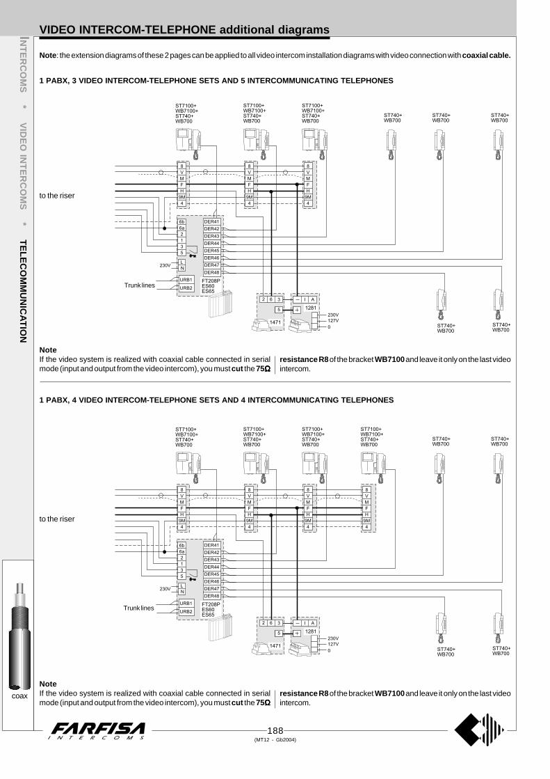
188(MT12 - Gb2004)
1 PABX, 3 VIDEO INTERCOM-TELEPHONE SETS AND 5 INTERCOMMUNICATING TELEPHONES
VIDEO INTERCOM-TELEPHONE additional diagramsINT
ER
CO
MS
* VID
EO
INT
ER
CO
MS
* TE
LE
CO
MM
UN
ICA
TIO
N
1 PABX, 4 VIDEO INTERCOM-TELEPHONE SETS AND 4 INTERCOMMUNICATING TELEPHONES
coax
NoteIf the video system is realized with coaxial cable connected in serialmode (input and output from the video intercom), you must cut the 75ΩΩΩΩΩ
resistance R8 of the bracket WB7100 and leave it only on the last videointercom.
NoteIf the video system is realized with coaxial cable connected in serialmode (input and output from the video intercom), you must cut the 75ΩΩΩΩΩ
resistance R8 of the bracket WB7100 and leave it only on the last videointercom.
Note: the extension diagrams of these 2 pages can be applied to all video intercom installation diagrams with video connection with coaxial cable.
to the riser
to the riser
Trunk lines
Trunk lines

189(MT12 - Gb2004)
INT
ER
CO
MS
* VID
EO
INT
ER
CO
MS
* TE
LE
CO
MM
UN
ICA
TIO
NVIDEO INTERCOM-TELEPHONE additional diagrams
1 PABX, 6 VIDEO INTERCOM-TELEPHONE SETS AND 2 INTERCOMMUNICATING TELEPHONES
1 PABX, 5 VIDEO INTERCOM-TELEPHONE SETS AND 3 INTERCOMMUNICATING TELEPHONES
coax
NoteIf the video system is realized with coaxial cable connected in serialmode (input and output from the video intercom), you must cut the 75ΩΩΩΩΩ
resistance R8 of the bracket WB7100 and leave it only on the last videointercom.
NoteIf the video system is realized with coaxial cable connected in serialmode (input and output from the video intercom), you must cut the 75ΩΩΩΩΩ
resistance R8 of the bracket WB7100 and leave it only on the last videointercom.
to the riser
to the riser
Trunk lines
Trunk lines

190(MT12 - Gb2004)
1 PABX, 3 VIDEO INTERCOM-TELEPHONE SETS AND 5 INTERCOMMUNICATING TELEPHONES
VIDEO INTERCOM-TELEPHONE additional diagramsINT
ER
CO
MS
* VID
EO
INT
ER
CO
MS
* TE
LE
CO
MM
UN
ICA
TIO
N
1 PABX, 4 VIDEO INTERCOM-TELEPHONE SETS AND 4 INTERCOMMUNICATING TELEPHONES
NoteOn bracket WB7100 you must move jumper J2 from position 1-2 to 2-3.
twistedpair
Note: the extension diagrams of these 2 pages can be only applied to Si311T/4, Si31MT/2 and Si32MT/1 installation diagrams (page 177, 181and 183, respectively) because of the video connection with twisted pair.
to the riser
to the riser
Trunk lines
Trunk lines
NoteOn bracket WB7100 you must move jumper J2 from position 1-2 to 2-3.

191(MT12 - Gb2004)
INT
ER
CO
MS
* VID
EO
INT
ER
CO
MS
* TE
LE
CO
MM
UN
ICA
TIO
NVIDEO INTERCOM-TELEPHONE additional diagrams
1 PABX, 6 VIDEO INTERCOM-TELEPHONE SETS AND 2 INTERCOMMUNICATING TELEPHONES
1 PABX, 5 VIDEO INTERCOM-TELEPHONE SETS AND 3 INTERCOMMUNICATING TELEPHONES
twistedpair
to the riser
to the riser
Trunk lines
Trunk lines
NoteOn bracket WB7100 you must move jumper J2 from position 1-2 to 2-3.
NoteOn bracket WB7100 you must move jumper J2 from position 1-2 to 2-3.

192(MT12 - Gb2004)
List of article that can be used in electronic call systems with page reference.
337C Electric door-speaker for ErreP/R push-button panel476 5-output video distributor910W White open-voice intercom Slim series924W White intercom Slim series1273TV 7-contact exchanger1281 Video power supply1283 Back box for PT5660 and PV12601304 Video intercom cable with 10 wires + coaxial1382 Audio-video timer1443E Intercommunicanting module1471 Relay unit1471E Relay unit1472 2-contact relay unit1473 4-contact exchanger2443 Audio-relay amplifierCV01 Video signal converterDV2 2-output video distributorDV2D 2-output video distributorDV4 4-output video distributorDV4D 4-output video distributorES60 Intercom interface with 2 relays for FT105P and FT208PES65 Intercom interface with 4 relays for FT105P and FT208PES70 Caller identifier board for FT105P and FT208PFC52P Access control keypadFP52 Proximity readerFT11D Intercom-telephone interfaceFT105P PABX with 1 trunk line / 5 internal linesFT208P PABX with 2 trunk lines / 8 internal linesMA10P Module with integrated audio and without buttons; Matrix ser.MA11P Module with integrated audio and with 1 button; Matrix ser.MA12P Module with integrated audio and with 2 buttons; Matrix ser.MA20 Blank module; Matrix seriesMA22 Module with 2 call buttons; Matrix seriesMA24 Module with 4 call buttons; Matrix seriesMA42 Camera module; Matrix seriesMA42C Colour camera module; Matrix seriesMA43 Camera module; Matrix seriesMA43C Colour camera module; Matrix seriesMA61 Front frame for 1 module; Matrix seriesMA62 Front frame for 2 modules; Matrix seriesMA63 Front frame for 3 modules; Matrix seriesMA71 Back box with frames for 1 module; Matrix seriesMA72 Back box with frames for 2 modules; Matrix seriesMA73 Back box with frames for 3 modules; Matrix seriesMD10 Module for door speaker without push-buttons; Mody seriesMD11 Module for door speaker with 1 push-button; Mody seriesMD12 Module for door speaker with 2 push-buttons; Mody seriesMD20 Blank module; Mody seriesMD21 Button module with 1 push-button; Mody seriesMD22 Button module with 2 push-buttons; Mody seriesMD23 Button module with 3 push-buttons; Mody seriesMD24 Button module with 4 push-buttons; Mody seriesMD30 Electric door speaker; Mody seriesMD41 Camera module; Mody seriesMD41C Colour camera module; Mody seriesMD41D Camera module; Mody seriesMD50 Street number module; Mody seriesMD71 Back box with frames for 1 module; Mody seriesMD72 Back box with frames for 2 modules; Mody seriesMD73 Back box with frames for 2 modules; Mody seriesMD74 Back box with frames for 2 modules; Mody seriesMD81 Hood cover for 1 module; Mody seriesMD82 Hood cover for 2 modules; Mody seriesMD83 Hood cover for 3 modules; Mody seriesMD84 Hood cover for 4 modules (2 frames with 2 modules)MD804 Hood cover for 4 modules (1 frame with 4 modules)MD86 Hood cover for 6 modules (2 frames with 3 modules)MD808 Hood cover for 8 modules (2 frames with 4 modules)MD89 Hood cover for 9 modules (3 frames with 3 modules)MD812 Hood cover for 12 modules (3 frames with 4 modules)MD91 Rain shelter for 1 module; Mody seriesMD92 Rain shelter for 2 modules; Mody seriesMD93 Rain shelter for 3 modules; Mody seriesMD94 Rain shelter for 4 modules (2 frames with 2 modules)MD904 Rain shelter for 4 modules (1 frame with 4 modules)MD96 Rain shelter for 6 modules (2 frames with 3 modules)MD908 Rain shelter for 8 modules (2 frames with 4 modules)MD99 Rain shelter for 9 modules (3 frames with 3 modules)
MD912 Rain shelter for 12 modules (3 frames with 4 modules)MD100 Amplified door station with 1 push-buttonMD122 Module for door speaker with 2 push-buttons, 2 rowMD124 Module for door speaker with 4 push-buttons, 2 rowMD200 Amplified door station with 2 push-buttonsMD222 Button module with 2 push-buttons, 2 rowMD224 Button module with 4 push-buttons, 2 rowMD226 Button module with 6 push-buttons, 2 rowMD228 Button module with 8 push-buttons, 2 rowPR1 Protection for 1 telephone linePR2 Protection for 2 telephone linesPRAL Protection for electrical linePRS210 Transformer 13Vac - 15VAPRS220 Intercom power supply 6Vdc/13Vac - 15VAPRS226 Power supply-switcher for intercommunicating 18VAPRS226E Power supply-switcher for intercommunicating 18VAPRS235 Power supply for private conversation 18VAPRS240 Power supply with electronic ringing 7Vdc/13Vac - 18VAPT501 Single button unit for PT520,N,WPT502 LED module for PT520,N,WPT510 Bicolour intercom Project seriesPT510N Beige intercom Project seriesPT510W White intercom Project seriesPT515 Switch module for PT520,N,WPT520 Bicolour extendable intercom Project seriesPT520W White extendable intercom Project seriesPT524W White intercom with carbon microphonePT538 Desk adapter for intercom Project seriesPT5160 Two colour Flat videointercom Project seriesPT5160W White Flat videointercom Project seriesPT5160W-LCD Colour Flat videointercom Project series. White colourPT5660W White videointercom Project seriesPT5860 Two colour reflex videointercom Project seriesPT5860W White reflex videointercom Project seriesPV100 Bicolour intercom Puntovirgola seriesPV100W White intercom Puntovirgola seriesPV1260 Two colour videointercom PuntoVirgola seriesPV2160 Two colour Flat videointercom PuntoVirgola seriesPV2160W White Flat videointercom PuntoVirgola seriesR8 Push-button panel with 8 buttons ErreP/R seriesR10 Push-button panel with 10 buttons ErreP/R seriesR12 Push-button panel with 12 buttons ErreP/R seriesR14 Push-button panel with 14 buttons ErreP/R seriesRL36 Relay module for intercoms Project seriesRL37 Relay moduleRP1 Push-button panel with 1 button ErreP/R seriesRP2 Push-button panel with 2 buttons ErreP/R seriesRP4 Push-button panel with 4 buttons ErreP/R seriesRP6 Push-button panel with 6 buttons ErreP/R seriesRP8 Push-button panel with 8 buttons ErreP/R seriesRP10 Push-button panel with 10 buttons ErreP/R seriesRP12 Push-button panel with 12 buttons ErreP/R seriesRP100 Amplified door station with 1 push-buttonRP200 Amplified door station with 2 push-buttonsSM50 Private conversation module for intercom ProjectSR40 Electronic bell module for intercom ProjectSR41 Electronic buzzer module for intercom ProjectST740W White telephone Studio seriesST7100W White Flat monitor Studio seriesST7100CW Colour Flat monitor Studio series. White colourST7M32W 32-image video memory for Studio seriesTA700W Desk adapter for ST740W telephone Studio seriesTA5160 Desk adapter for PT5160W videointercomTA7100W Desk adapter for ST7100W monitor Studio seriesUP11 Amplified door station with 1 push-button, flush mountedUP12 Amplified door station with 2 push-buttons, flush mountedUP100 Amplified door station with 1 push-button, surface mountedUP200 Amplified door station with 1 push-button, surface mountedWB700 Wall bracket for ST740W telephone Studio seriesWB1200 Wall bracket for PV1260 videointercom; for 2 push-buttonsWB1260 Wall bracket for PV1260 videointercom; for addit. buttonsWB2100 Wall bracket for PV2160 videointercom; for 2 push-buttonsWB2160 Wall bracket for PV2160 videointercom; for addit. buttonsWB5100 Wall bracket for PT5160 videointercom; for 2 push-buttonsWB5160 Wall bracket for PT5160 videointercom; for addit. buttonsWB5600 Bracket for PT5660, PT5860 videointercoms; for 2 buttonsWB5660 Bracket for PT5660,5860 videointercoms; for add. buttonsWB7100 Wall bracket for ST7100W monitor
Article Description Page ref.
PRODUCT LIST
Article Description Page ref.
2293
66
9190759690902525252590
17292969296
167167166
99
162164164
17171717171786868686161616161616
888888888
818186
8777777777777777777777
798898888
163163163
242424242424
4455544455
727272747676
66
79787822222222
491222222222222222222
555
150154154160150
73154
23232323
1508080787872727474
154

Due to continuous technological evolution ACI FARFISA reserves the right to modify the products, technical specifications and installation diagrams contained in thismanual at any time without prior notice.The diagrams and information contained in this manual have been carefully verified and are to be considered as reliable. However, ACI FARFISA is not responsible forany errors, inaccuracies or infringements to patents and third-party rights that may arise from using this manual.