Alternate-Curre Transformers - Forgotten Books
111
-
Upload
khangminh22 -
Category
Documents
-
view
5 -
download
0
Transcript of Alternate-Curre Transformers - Forgotten Books


P R E F A C E .
THE inven tion of the alternate-current transformer some years ago
led to the introduction of th e system of high -tension distribution of
electric energy for lighting purposes. The saving in th e first cost of
the copper mains being the chief advantage of th e system in the
eyes of the promoters , the quest ion of the efficiency of this methodof supply, except at full load
, was not considered . Now, experience
has shown that the cost of the annual supply depends largely on th e
efficiency of the transformers used , and that the loss at light loadsis the most importan t factor in determining this cost .
Hence the design of alternate-current transformers needs more
careful attention as the demand for higher efficiency arises.
I have endeavoured in the following pages to describe as simplyas possible the principles involved in the construction of transformers
on economic lines, both as regards first cost and power wasted whenworking . To the formulae deduced from these principles I haveadded several others which are useful when determining quickly th e
dimensions of th e various circuits. To enable more to follow th e
reasoning , higher mathematics have been avoided , although th i s
omission has necessitated the acceptance of certain well -knownformulae without proof.The examples worked ou t and illustrated show the general pro
cedure of designing transformers of different types to fulfil definite
conditions .
R. W. VVEEKES.

Brown -Boveri TransformerCircuit
,I ron
Circuits , Perimeter ofCircuits , S ize, CopperConclusionsCondensers , U se with TransformersCooling Surface 22
, 39, 57 , 73Copper Circuit , First DesignCopper in Circuit sCopper LossCore . . 43 ,
Design, LongShell Type , Square CoreDesign , Mordey TypeDesign
,Third
Design ing , Routine i n
Detai ls , F1rst DesignDetails , Second or Mordey DesignDetails , Third DesignEarly Designs , Faults inEfficiencyEfficiency and FrequencyElwell -Parker TransformerE HM F . in CoilFaults in Early DesignsFerran t i TransformerFirst DesignFleming’3 Table, Transformers TestedFoucault CurrentsFrequencyFrequency and EfficiencyHedgehog TransformerHysteresi s
4
7 15 0 ,2,
73
53,
5
56 ’
321776 1 ,S9 ,

PAGE
1 2 , 20 , 3 5 , 49, 56, 66,
Mordey Type TransformerOerlikon TransformerPermeabilityPower FactorPrinciples involvedRoutine in DesigningS ine LawS tampingsS teinmetz on HysteresisSwinburne’s TransformerTests , Fleming ’sTransformer Formula for E HM F .
Transformer LoadsTRANSFORMERS
Brown Boverifor Different MethodsOfSupplyElementaryElwell-ParkerFerrantiLarge SmallLaw of
OerlikonTableof TestsWestinghouse
Value of ,u.
VoltageWest inghouse TransformerWindings , Determination , First DesignWindings
,Mordey Type
Wire , First Design


TH E D E S I GN
ALTERNATE CURRENT TRANSFORMERS .
The reliable information available on the subjectof alternate-current transformers has unt i l recentlybeen very scanty. When .the high tension systemof d istribution , with transformers in parallel , wasintroduced some eight years ago, the good po ints ofthe transformers as then made , were much exaggera
ted . I t was generally stated that the efficiency atall loads was very high , and that the current takenby the primary when no lampswere on the secondarycircu it was so small as to be almost neligible. The
last statement may be excused to some extent whenit is remembered that small current measurementscould not be made so readily then . Stil l , the
engineers in charge of central stat ions have foundthat the small currents required to energise eachtransformer soon become a serious item in the costof product ion .
,In consequence of their experiencethey now specify what the various transformersshould be capable of doing, and by rais ing the
B

I O The Design of
standard of their requ irements induce the makers tomake further improvements .
The faults existing in the early designs of transformers may be briefly summarised as follows : Badregulat ion , that is , the pressure at the secondaryterm inals varied considerably with the load . Hence
,
when the primary circuit was supplied at a constantd ifference of potential , the consumer found that thevoltage fell as he increased the number of the lampsburn ing . Th is fault was partly overcome by increasing the primary voltage slightly, when the load cameon , but th is does not remove the fault unless allconsumers take the full load at the same hours .
Otherwise , in some installations , a few lamps m ightbe seriously overrun by the r ise in pressure .
Another more important fault , was the comparat ively large current taken by the primary when therewas no load on the secondary . Th is is due in a largemeasure to the loss by hysteresis and Foucaultcurrents in the iron core , which in some of the earlyt ransformers amounted to from I O to 20 per cent . ofthe total output . In addition to these two principal
.
fail ings , there were several others in a large measureresulting from them , such as the high temperatureof the transformer even when not loaded , faultyinsulat ion between the two wind ings , etc . ,
The various makers have since that t ime donemuch to reduce these faults to a m in imum , but themethods used to this end and the general pract ice oft he design of tran sformers is st ill
’
known to comparat ively few. This is partly due to the tendencyamongst many writers on the subj ects to treat

Alternate Current Transformers . 1 1
m m moo m oo m h ")
3
,
n b
,
n n n

1 2 The Design of
I
transformer design as a field for mathemat icalexercise . In this way a lot of really unnecessary “
mathemat ics is often introduced wh ich frightens the
great maj or ity of electrical engineers .
The recent paper by Dr . Fleming , read before the’
Inst itution ofE lectrical E ngineers in November , 1 892formed the most practical contribution to the l iterature on the subj ect . The l ist given in the paper ofthe actual losses in some 1 8 different transformers isa rough guide as to what may be expected of themodern transformer. I t must be remembered when .
exam in ing the tabl e which is given before , that thetransformer-makers are rapidly improving the irmanufactures , and hence some of the results may be
already out of date . The comparison of the Ferrantitransformers made in 1 892 w ith those of 1 885 willshow the vast difference between the old types andthose perfected by careful study .
In add ition to the columns found in Dr. Flem ing’stable , I have added five others , showing the percentage of magnetising current and iron loss in each case ,and also the figures relating to the regulat ion of thevarious transformers wh ich are taken from otherparts of the same paper . In th is form the list is of
great value for reference when gett ing out newdesigns .
All the transformers in the l ist were wound andreduced from volts to 1 00.
The importance of reducing the i ron loss will beseen when it i s remembered that an average privatehouse takes from five to twenty Board of Tradeunits per year per 8 -c .p. lamp installed . I f we

Alternate Current Transformers . I 3
aconsider a house having 1 20 of such lamps fixed , itm ight safely be supplied by the second transformeron the l ist . During the year it might take and payfor 1 3 un its per lamp , or 1 20 x 5 60 un its for thew hole supply . But the transformer has 1 46 percent . of iron loss , or wastes 5 45/watts continuously.
Taken over th e hours in the year , this amounts
toM units un its . That means that
four t imes the quantity paid for has to be generated .
The efficiency of d istribution is then per
c ent . , neglecting the loss in the line . Now, if the ironloss were reduced to 2 per cent , wh ich may be reasonably expected , the annual waste in the iron is then
7 5 x
loss , the efficiency of distribution r ises to 70 per cent .With other consumers , such as clubs and shopkeepers , the efficiency wi l l be considerably over
90 per cent . if the load is steady for any length oft ime .
The copper loss is important at full load , butdecreases as the square of the current used , and somay be neglected at l ight loads . Thus , if the copperloss is 2 per cent . at full load it falls to
‘
5 per cent .at half load ,
'
1 25 per cent . at one-quarter full load,
a nd to °
02 per cent . at one-tenth of full load . H ence,
the regulat ion requ ired does more to determine the"copper loss allowable than the cons iderat ion of thea ctual waste in the copper circu its .
Before going into the actual calculat ion of a
65 5 un its ; so that , neglecting copper

1 4 The Design of
transformer it w i l l be well to give a short‘
t ion of the fundamental principles involved iscovery by Faraday that any change of i nduct ionin an iron core surrounded by a co i l of
'
wirecaused an instantaneous E .M. .F in the wire , isemployed in transformers , and the E .M.F . is madepract ical ly cont inuous for heating and light ingpurposes by an ever-ch angmg 1nduct i0n in theThe elementary transformer , Fig. 1 , consists of an .
F IG. 1 .
iron circu it , C , and two copper circu its , P and S ,
arranged that th e fluctuating current in the primary , .
P ,causes a change of induction in the iron core ,
wh ich again sets Up a current in the other copper"
curcu it , S .
I t is in determin ing the best relat ive proport ionsof these circu its for any given result that the art ofthe designer has to be appl ied . He was alwaysdependent on the iron manufacturer for the quality“
of the iron he uses , and needs to keep a constant .

A lternate Carrent Transformers . 1 5
watch by testing the iron as it is del ivered . In
Spite of this disturb ing and ever altering element inthe sequence of the designs , i t is wrong to blame theiron manufacturer for all the faults wh ich
.may occur,
as is often done . The relative value of two designsis not altered much by a change in the qual ity of theiron used . Hence , the calcu lations made , if carefully recorded , together with th e qual ity of ironassumed
,have always a relat ive value , and can easily
be altered to show the improvement made in thetransformer if a better brand of iron can beobtained .
In the following investigat ions it i s assumed thatthe E .M. .F curve of the alternator follows thesimple s ine law . This is
‘
strongly objected to bysome writers , who advocate the method of takingthe actual curves from the alternators with whichthe transformers have to be used . Th e publ ishedcurves of alternators made in England , however,d iffer very sl ightly from the curve of sines , and thet ime wasted in hunt ing up curves and introducingthe correct ions from them in the formulae wouldnot be worth / the slight additional accuracy obtained .
The makers would not think of altering their stockpatterns for so slight a difference in the workingcond it ions as will be found between the E .M.F
curves of d ifferent types of alternators , and henceit is better in every way to work on the aboveassumption .
The generated in a coil of wire throughwhich the induction is varied is equal to the productof the number of turn s into the rate of change of

1 6 The Design of
t he induct ion , all these quantities be ing expressedin '
absolute un its . From th is law it follows that ina transformer the volts as measured in a Cardewvoltmeter are g iven for the primary circu it by theexpression
el
7: F 71n 1 0
—8,
where e1= the E .MHF as defined above , in the
primary ;e2= the E .M. .F as defined above , in the
secondaryF .
= the maximum total flux -1 ? x a ;
a = the area of the iron in the core in squarecent imetres
Q the maximum induction in the core111= the number of turns in the primary ;
7 2= the number of turns in the secondary ;
n = the number of complete periods per
second— a period being an oscillationto and fro
being the coefficient which reduces theE M F . from absolute units to volts .
The above formulae can be best remembered as
el=4
'
4s F 7 ,n
S im ilarly the E .M.F in th e secondary is given by
e2=4
°
45 F 7-
2 n 1 0- 3
.
-D ivid ing one by the other we get
el _'z-
l
32 7 2
or, that the number of turns wound on each co i l
must be made proport ional to the voltage requ iredin the wind ings .

Alternate Current Transformers. 1 7
I t is also seen that with a fixed frequency andnumber of turns , any given voltage is produced by adefin ite flux through the core . A mental p icture of
the equilibr ium maintained is useful in making th is clear . Whenthe secondary circu it is open werequ ire that the back in theprimary shall rise to a value almostequal to the potential d ifference applied , otherw ise a large current willpass ; but a large current in theprimary with the secondary openmeans that the core of the transformer will be strongly magnetised ,and hence give a large backThus , when the magnet ising currenthas risen to such a value as toproduce the flux given by theformulae above , no further r ise ispossible , as it would cause thetransformer to give power back tothe mains because the back E .M.F
would be higher than that on themains .
From these cons iderat ions italso follows that t he induct ion
FIG 2 in the core must be pract icallyconstant at an loads , because
the primary circuit is supplied at constant potent ial .. Thus while the primary current is in
c reased by loading the secondary , the resultantmagnet ising current must be the same . Th is is

1 8 The Design of
explained by the fact that th e primary and ;
ary currents practically oppose each other in
act ion on the core .
Fig. 2 shows the condition of affairs when thetransformer is loaded .
e1 represents in magn itude and d irect ion the primaryvoltage applied ;
i , is the primary current , wh ich lags a l ittle behi nd
3 1 ;
F IG. 3.
i2 is the secondary current , wh ich is pract icallyopposed in phrase to e1 ;
e, , the secondary would be in the same lineprovided the external load is non-inductive .
The resultant of i 1 and i2 obtained by the usualconstruct ion is O b, which represents the current "
actually requ ired to magnetise the iron . Th is ishere called in, as the permeability of the irondeterm ines itsmagn itude . Now i 1 can be spl itup into

20 The Design of
w here t= the mean length of the path taken by theinduction in centimetres ;"= the max imum induction in C .G .S . units ;
,u.= the permeability of the iron at that induc
t ion ;7 1= the number of turns on the primary coil .
Having thus obtained in, we can get i the no loadc urrent because as i n x in thus form the two sideso f a right angled triangle, the ir resultant i is got byt aking the square root of the sum of the ir square or
O C2 C B2 O B2
ifr: if in
?
i _ J i n2 ip
fi.
Th e rat io of the current taken by the transformera t no load to the current actually required for thehysteres is has been called the power factor" byDr. Flem ing, and this gives us the factor by wh ichthe apparent watts have to be mult iplied to get thet rue watts wasted . For good closed circu it transformers this factor varies from '
60 up to nearly ‘
90
As regards the curves of iron losses . Theses hould be carefully obtained for each sample of ironu sed in the transformers . I t is possible to subd ividet he loss into two — that due to eddy currents ln thei ron and that due to hysteresis pure and s imple .
Mr. C . P . Steinmetz has worked cont inuously atth is subj ect for some years , and concludes that thehysteres is losses vary as the frequency and as the1
'
6th power of the induction , or H a n Q“ ;
wh ile the FoucauIt currents vary as (n or
F =b (n where a_and b are constants .

Alternate Current Transformers . 21
The simplest way is to calculate the Foucaultcurrent loss , wh ich if the core is wel l subdivided , isnot a large percentage of the whole , and then to getthe hysteresis loss by subtraction . For instance ,using the generally accepted formula?e the eddycurrents in a pound of iron subj ected to an induct ionof at a frequency of 1 00 complete periods persecond works out to '
08 watt if the plates are ten
m il s th ick , and to °
1 8 watt if the plates are 1 5m i ls th ick . The watts lost per pound in hysteresiswi l l vary about the region of one watt per pound ,being more or less accord ing to the qual ity of thei ron . So that with the thin plates the eddy-currentloss is under 8 per cent . of the total . I t i s alsoconvenient to plot the total iron loss for a givenfrequency at d ifferent induct ions , and such a curvewil l be added for reference .
The other theoretical considerat ions to be remembered in design ing a t ransformer are of a more
general nature , such as keep ing the copper circu itsof as small a perimeter as possible . The same
appl ies to the iron circu its , as any undue length inthe 1ron increases both the iron loss and the idlecurrent when the tran sformer is unloaded . In fact ,these points are so easily expressed in formula thatthere have been many attempts made to deduce praot ical conclusions as to the best design from thesealone . The results thus obtained have not been
For thin iron plates th e watt s lost per cubic cent imetre at 00 F ,
7 ( t as n )210
"- 10
where t the thickness of the plate in inchesB the maximum inductionn the frequency.

22 The Design 0]
s at isfactory as a whole , and somet imes have led tom istakes in pract ice .
The question of the cooling surface to be al lowedis one of the most vital importance . Th e custom ofenclosing transformers in cast- iron cases tends toincrease the d ifficulty of preventing the temperaturebecom ing too high . The heat generated in thet ransformer has to pass first from it into the surround ing air inside th e case , then from this layer ofa ir into the case , and finally from the case into thesurround ing med ium . This triple transference is
greatly assisted i f oil is used to fi l l in the case . The
o il acts by conduction and convection in carry ingthe heat to the case , and thus materially reducest he final temperature of the transformer . The
oil is primarily said to be used for insulat ion purposes , but its action as a cooling agent is at lowvoltages the more valuable of its propert ies .
The actual design of the sect ions of the two copperc ircuits for a given loss is a problem similar to thoseoccurring in dynamo calculation , and presents nonew d ifficult ies .
The following formula , wh ich are s imply deduct ions from the specific resistance of copper will befound very useful in determin ing the sizes of thec opper circuits :I f s = the sect ion of the w ire in square inches ;ti = the diameter of the wire in inches ;i = the maximum current in amperes , as read on
a S iemens dynamometer ;7 = the number of turns in the circuit ;7r= the mean length of a turn in feet ;

A lternate Current Transformers. 23
l = the total length of conductor in feet6= the drop of volts allowed at maximum
currentr = the resistance in ohms ;
g= the weight of copper in pounds .
Then for rectangular sect ions
i a- 7r 9'
z
g= s 1 r x
7 7r can in each case be replaced in the above by I,"
but it is well to record the mean diameter in eachd esign .
With wire of circular sect ion these formula become
1 7 77
1 0—3
The constants and give the respect ives izes and resistances at a temperature of about1 05deg . F . , wh ich may be considered as a fairallowance for heat ing , and on assumpt ion that thec opper is of 1 00 per cent . conduct ivity. I f a h ighertemperature is allowed , or inferior copper is used ,these constants must be modified accord ingly .
There is , however, one other important point tobe considered , and that is the question of magnet ic

24 The Design of
leakage . When most transformersbe found that the drop in volts i
a mt. ya a
) ,m a, 9m m
between no load and fu ll load is more than can beaccounted for by the resistances of the copper cir

Alternate Current Transformers . 25
cuits . Th is is due to the fac t that at full load th ewho le field p roduced by the primary does not passthrough the secondary , but some port ion of it 18
forced out by the action of the secondary current ,and consequently we get a drop in volts . Th is is animportant point , but it will be more read ily understood after the trial designs have been given .
I t will be best to assume a given quality of irontaken from pract ical test , and hence the two curves
given have been prepared . Fig. 4 gives the
watts lost per pound of iron at 1 00 frequency withvarying induction . For sl ight alterations of frequenoy it wi ll not cause a serious error to assume
that the loss varies d irectly as the number of“
com
plete periods per second , as the plates for wh ich thecurve is drawn were 1 0 mils thick . The iron is notthe b est that can be obtained , but st ill is a fairly
good sample . The a
other curve , Fig. 5 , giving thepermeabil ity, ,
u. , for the various inductions , was alsocalculated from actual results with the same iron ,and wil l be used when working out the open-circu itcurrents . I t wi ll be noticed that the curve graduallyrises t ill the induction reaches and after thatit is nearly flat . I f carried farther the curve fallsagain , but it is not usual to work at h igher induct ions .
With superior qualities of iron the,u. curve is raised
throughout its entire length , but the most not iceablefeature of the change is that the permeabil ity at lowinduct ion is very much increased .
The following is a useful rout ine to adopt inmaking designs : First fix the iron and copper lossesto be allowed from the considerat ions of the work to
c

26 The Design of
be done . Then fix "roughly the d im ensions of theiron circu it and calculate the weight of iron . From
the i ron loss obtain the loss per pound , and hence ,from Fig. 4, the induction . Th is , mult iplied by the

28
abovemethod ofworking. The reader canself try the effects of small alterations incircuits on the efficiency and cost .
be taken as a fair efficiency to be aimed at as a firstattempt : Iron loss , 1 50 watts 2% per cent . of thetotal output . Copper loss, 60 watts in each circuit

A lternate Current Transformers . 29
'
a t full load , or a total Copper loss of 2 per cent .
Transform ing rat io , volts to 1 00 at full load .
Thus it will be well to make the rat io 2 ,000 to 1 02 at noload to reduce the effect of. the copper drop and magztnet ic leakage . The frequencywe wi l l assume to be 1 00c omplete cycles per second . The designs will be taken.at random , and will not necessari ly be the most economical of the various types . The cost of materialmay be taken as giving some ind icat ion of theprobable cost of manufacture . So, assum ing thec opper to cost 1 od . per pound , and the iron 4d . , weshall work out in each case the cost and weight perkilowatt output .First Design .
-Th is shall be of the long shell typehaving a square core . This form of transformer islargely used both on the Continent and in England ,but the d ifferent makers use various method s ofbu ilding up the core and of winding the copperc ircu its . We wi l l assume that a 4in . core is required ,and that the general outline of the iron circuit i s
that shown ln Fjg. 6 . The gross area of the sectionof the core is then square inches , and allowing
“
for 85 per cent . of the space be ing taken up by theiron , th is g1ves a core area of square inches , or84
°
5 square centimetres . Adding up the lengths of thevarious parts we get a total length of48in . , wh ich givesa volume of 630 cubic inches of iron , weigh ing 1 76h .
Now the total iron loss was to be 1 50 watts , sot hat the loss in hysteresis and Foucault currents
1 5 0
1 76
F ig. 4, it will be seen that th is corresponds to an
for I lb of iron is ‘85 watt . From the curve ,

30 The Design of
induction of about l ines per square "cent i"
metre .
H ence the total flux F x 845 .
From this we can now by aid of (1 ) determ ine thenumber of turns required in both wind ings . For
‘
the secondary we have
32 F 7 , n 1 0—8
and in this case1 02 , F n 1 00 ;
1 028 0
x 1 00 xx 1 0 7 5 5 °
An even number of turns must be used for convenience, and hence 76 will be nearest to t he
number required . I t is always well to calculate thesecondary first , and to obtain an even number of
turns in it , as it is not well to introduce half andquarter turns in either of the windings . We get thenumber of turns on the primary from the rat io of
th e voltages .
7 1
The next step to be considered is the arrangementof th e copper circuit . I t is found that if the coilsare wound separately and placed one at either endof the core , as shown in F ig. 1 , a large magnet icleakage takes place at full load . This causes a dropin the voltage
,which is very obj ect ionable , as .
explained above There are several methods of
obviat ing this defect , and one is to split the twotv


3 2.a The
‘
Design of
wind ings into sect ions , which are placed alternatelya long the core , Fig . 8 . In this way the demagnet ising effect of the secondary is not concentrated atone part of the core , and by the subdivision themagnetic leakage is reduced to reasonable l im its .
So in this transformer we will make four segmentsin the secondary, and interleave them with four of
FIG. 7
primary wire . The necessary rad ial insulat ion willbe about that shown in Fig . 7 , and the depth ofwind ing we may assume to be I i in . The meanc ircumference of the winding will then be 1 °
97ft .= 7r.
Design ing the primary first and using round wirefor it , we get from (4)
d di v
9

Alternate Current Transformers . 33
H ere i 3 amperes7 1
: turns ;7: 1
'
97ft . 0= 20 volts = 1 per cent .2 ,940ft
3 X X I°
97 x I I'
7 5
20
°
o72.
Thus , wire 72 mils diameter will give the 1 per
c ent . loss at ful l load . The insulat ion and clearancerequ ired in winding would bring the pitch of the wireup to about 90 mils . D ividing the depth of wind ing
I 7 S.
09
wh ich could be got in . In each segment ofwinding itis well to have a sub-d ivision , so that each half can bewound separately from th e bottom . This gives greaterinsulat ion , and less difference of potential betweenadjacent wires, than winding all in one division . So
by th is , we get 1 9 4 as the number of layers
there should be turns to each segment of
primary wire and half this number in eachcompartment As it is well to work to even numberswhere possible , we could wind five compartmentsw ith 1 9 layers. of 1 0 turns and three compartmentsw ith 1 8 layers of 1 0 turn s which would givet he total number requ ired . The actual length ofc ore taken up by the primary wire will be 8 x 1 0 x
As the mean length of turn may bea ltered in the final adj ustments , the other detai lsas to we ight of copper, resistance etc . , will be leftt i ll the actual dimensions are fixed .

34 The D esign of
Proceed ing. with the secondary copper, which on
account of its large size shou ld be of rectangularsect ion we use the formula in group
The sect ion , S , in square inches
i2 7 , 7r
01 0—6
In this case i2 60 amperes ;7 2
z : 76 ,
9 1 , and 7: as before ;so that l 1 soft .
60 x 76 x x
1
x— °
o83 sq .,in .
The number of turns 76 cannot be d ividedexactly by 8—
‘
the number of compartments— so thatwe must have a different number of turns in some ofthem . Thus , if we wind each segment with 1 9turns— one compartment having 1 0 turn s and one
n ine— we shall get the total number correctly. In
th is case it will be best to use tape and to allow for
1 0 layers . Thus ,1 7
15)1n .
give the th ickness of the
tape and the insulat ion °
1 7 5 in . Allowing 3 5 m ilsfor insulat ion , this leaves
°
1 4o in . for depth of copperand tape ; (
°
1 40in . x°6ooin .) wil l give the section
requ ired . This insulated tape wi l l thus measure
(°
1 7 5 in . x and the length of core taken up
by the secondary wi l l be 8 x'
°
63 5 5°
1 in.
Insulat ing flanges are required between the seg
ments and also between the two compartments ofeachsegment . The space taken up by these , with the
necessary winding clearance , wi l l be about

3 6 The Design of
requl red by the iron losses at open circu it
ampere in Fig. 3 .
The next step is to calculate in, the current re.
q u ired by the permeabil ity of the iron . This is got.by means of the formula (2)
$ 1
,u 7 1 I 7 6
For th is transformer, l, the mean length of themagnet ic path i n cent imetres , is 1 23
°
,u. at this induct ion , from Fig. 57 1
x 1 23x x
As from Fig . 3 , i H and in are the two s ides of ar ight -angle triangle , we obtain the magnet ising orn o- load current by taking the square root of the sumof the squares of these two . Thus
°o8s8 ampere .
i
°
1 1 2 ampere ;wh ich is per cent . of the full-load current int he primary .
Now comp let ing the detail s for the primary copperby
' aid of we get the resistance from7 7 7 1
521 75
1—60
x x
o n x°
o72
say 67 ohms .
7

Alternate Current Transformers. 37
It will be seen that when the full primary currentof three amperes is flowing, this gives a loss of 20 voltsas intended .
The weight is now obtained from
g= d2 71° 7 1
placing the respective values of a, 71° and‘
7 1 we get
g 46lb .
The secondary is next t reated in the same way byaid of which applies for strip or any wire whenthe sect ion is known .
7 2 71°
9 2
S
or, placing in the value as determ ined above ,
r76 x 1
‘
96 x 9’
21 0
— 6°
083°
01 66 ohm .
Hence , r
This when mult ipl ied by 60 amperes , the maximurrr
current , gives us a drop of one volt . These calculat ionsof the resistances of the primary and secondarywind ing check the accuracy of the previous work ,in wh ich a 1 7, drop was assumed .
The weight , g , equals S 7 2 7 :x and so
g°
083 x 76 x
47°
5 1b ~
Now collect ing the details of the design together,we get the fol lowing l istSix-Ki lowatt Transformer , Shell Type — Rat io of
transformat ion , volts ;A
v1 00 .
Core , 4in . square ; area of iron , square cent imetres .

3 8 The Design of
B F I : 1 23 .
Primary : 7 1 7 :
Conductor, 72-mil wire wound in four segments
o f two divisions as follows .
5 divisions of 1 9 layers of 1 0 turns .
3 1 8 I O turns .
Maximum depth of wind ing, 1°
7 in .
r 67 ohms ; loss 1 per cent . ; weight , 46lb .
Secondary : 7 2 76 . 7T'
Conductor , strip (°
1 40in . x wound in fours egments of two d ivisions , as follows
4 d ivisions of 1 0 layers of I turn , and
4 n n 9 n I turnMaximum depth of winding, 1 75 in .
r'
01 66 ohm loss 1 per cent . ; we ight , 47°
5 1b .
Losses— Iron watts , or per cent .Copper, primary 60 1
Copper , secondary 60 1
2648 watts .
Therefore the efficiency at full load
per cent .The watts wasted in the iron at no load are
and the apparent watts at no load volts x
°
1 1 2 ampere 224 watts .
1 44 8 °648 .
224The weight of iron 1 72
°
s1b . , at 4d. per lb . 5 7°
5 5 .
copper= 93°
5 lb . , at 1 od . per lb . 78 05 :
So the power factor in th is case
Total 266lb . 1 3 5°
5 s

Alternate Current Transformers .
D ividing by the output , we find that the resultsh ave been obtained by using 44
°
3 lb . of copper andiron per kilowatt , and at a cost of 226 3 . for thematerials ; also that the rat io of weight of copper towe ight of iron 5 5 .
The other point to be considered in the transformer j ust designed is the cooling surface per wattwasted at no load and also at full load . Th iss hould give an approximate idea o f the temperaturewh ich the transformer will attain when left on thec ircuit . The investigation is , however, by no meansso simple as might be expected at first sight .Suppose,for instance, we calculate the total coolings urface . The surface of the copper coils andinsulat ion may be taken as that of a cyl inder 95 h . diameter and 1 5 in . long, and thus 71
°
x gi lu . x 1 s in .
438 square inches . The end flanges may help to coolt he coils , and hence , the surface of these should beadded 36 square inches . The iron in the yokesw ill add considerably to the above , the exposeds urface of the iron is about 780 square inches .
s o that the total cool ing surface will be squareinches . The
’watts wasted at no load are andat full load the total loss rises to 2648 watts .
Working with these figures and the cooling surface
g iven above , the loss comes out at°
1 1 5 watt per square inch at no load , and°
21 1 at full load .
These figures appear ample , if viewed in the l ighto f dynamo magnet practice, but it must be remembered that dynamos have moving parts wh ich createc urrents of air round the field magnets , tend ing to

40 The Design of
make the cooling surface more effective , whereas .
the transformer not on ly is motionless, but is boxedup in an iron case wh ich prevents a free circulat ionof air . Thus the heat has to be transferred from the
transformer to the a ir in the case , again from th isair to the case , and finally from the case to the air
outside . Th is is not absolutely correct , as the
transformer loses heat by conduct ion where the
yokes rest on the iron box , but still , roughly, wemay expect at least two and a half times the rise oftemperature that would be found on a field magnethaving the same loss per square inch cool ing surface .
Much of course, depends on the shape andmechan ical construction of the transformer, and ind ividual constants should be obtained from pract icefor the heating formula for each type .
Now, in the above calculation , we have workedwith the total cooling surface and the total loss . Evenif the loss were un iform through the mass this would
give widely different internal temperatures accordingto the depth of material . It is, however, this internaltemperature that causes faults in transformers byheating the insulat ion on the wires up to a point atwh ich it either chars or becomes rotten . In the transformer designed above th e most dangerous pointwould be the bottom of the coil wound in the centreof the transformer . The heat generated in the ironimmediately under this would pass , to a considerableextent , up through the copper, and this heat has tobe d issipated by the surface of the copper as well asthe copper watts . Considering a vertical sectionmm. long, the iron loss in the part of the core thus

Alternate Current Transformers . 41
cut off would be watts , and the copper loss in th ewire would be about seven watts , giving a total lossin the section of watts . Now , the externalcooling surface is on ly 7: x gi in . 29 square inches ,so that th e watts per square inch coolingsurface inthis central section rises to at full load , whereasthe mean obtained abovewas on ly This is underthe assumption that th e whole of th e heat generatedin the section is transmitted radially to th e surface ,which is not absolutely correct ; but if the coil is inth e middle of the winding it is not l ikely to give offmuch heat to the adjacent coils which wil l be at
much the same temperature .
In comparing th e figures relat ing to the coolingof transformers th e hottest poin t of th e Coppercircuits should always be considered , and not th e
mean external temperature on ly . The h ighesttemperature in th e iron does not affect us much , asno i ll effect s occur from this cause un less the hottestpart of th e iron i s close to th e copper , which isseldom the case . Th e yokes in this design have thelargest amount of surface per watt wasted , and hencekeep cooler than th e centre core . Some makers havereduced th e section of th e yokes for this reason ,
asweight can be saved by so doing and the temperaturestill kept norma l . This , of course , causes a higherinduction in th e yoke , and as th e curve of iron lossrises rapidly with the induction , the watts per
pound will increase more rapid ly than th e weightdimin ishes . Hence the total iron loss is increasedby making th e yokes of smaller section . Again"
,
working in th e inverse direction ,some makers have
D

42 The Design of
put more section of iron in their yokes than in th e
core . This certain ly lowers th e iron loss slightly ,but , as will be found by actual trial , th e effect is not
F IG. 9.
very marked , and , perhaps , is hardly worth theincrease in labour and material charges .
The methods of constructing the iron cores for
ina- v1z . , in,
In this case £ = th e induct i on i n the air
l = th e length of th e air -
ga
th e M for air = 1 .
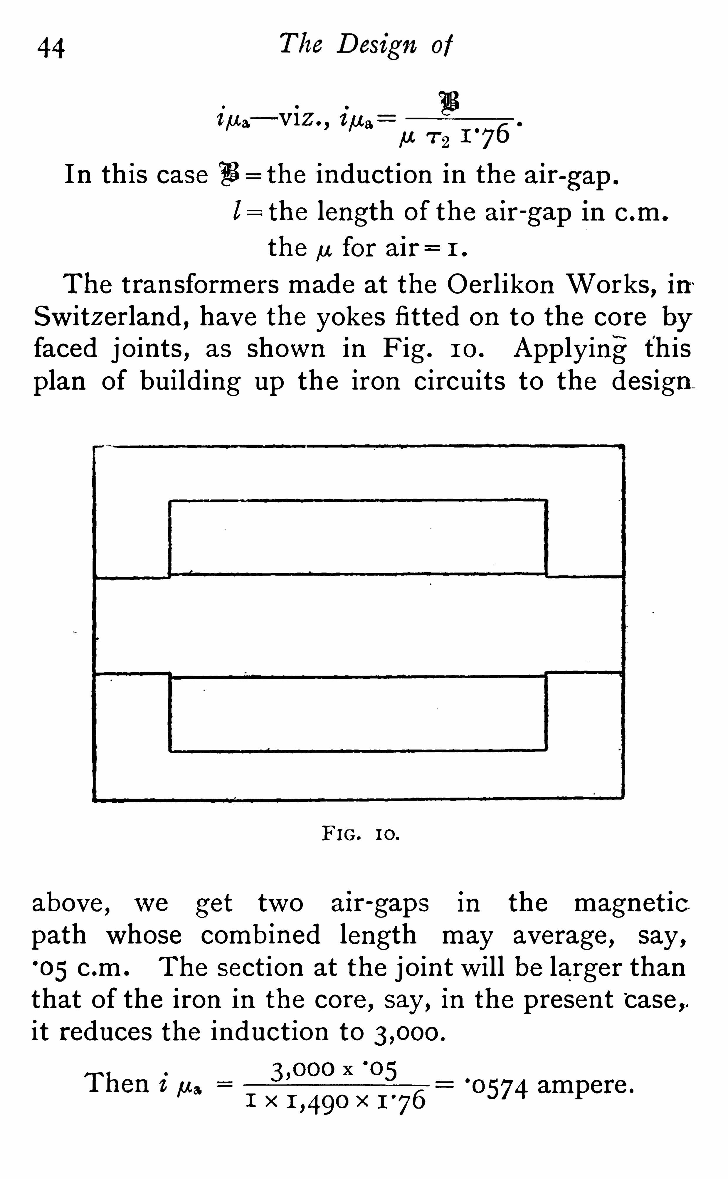
The t ransformers made at the Oerl ikon Works,in
Switzerland , have th e yokes fitted on to the core byfaced j oints , as shown in Fig . 1 0 . Applyingr thisplan of building up the iron circuits to the design
F IG. 10.
above , w e get two a ir -gaps in the magnet icpath whose combined length may average , say
,
°
05 c .m . The section at the j oint will be larger thanthat of the iron in th e core , say ,
in th e present ‘case ,it reduces th e induction to
x °
o51 X X
05 74 ampere .

Alternate Current Transformers . 45
T he,u current due to th e iron a lone as obtained
085 8 ampere. Th e total in therefore°
1 43 2 Working out th e total no- load current as
J°
o7z42 °
1 43 22,
ampere , or per cent .
that the effect of th e j oints is to raise the
F IG . 1 1 .
no- load curr/
ent from to per cent . of thetotal full - load current . The average length of airgap as taken above m ay be rather excessive , but itis extremely difficult to get good plane surfaces on
the cores and yokes which are built up of thinlaminations . Hence, although the faced j oints reducethe labour charges on the transformer , they havea lmost been abandoned in E ngland on account ofthe increase caused by them in the no -load current .

46 The D esign of
Fig . 1 1 shows this type of transformer’
a s made byMessrs . B rown and Boveri , of Baden . As W l ll be
seen the two yokes are in this case merged into one ,
and the system of winding is different to thatworked out in th e des ign above . The primaryand secondary wires are wound on insulatingcylinders separately
, and s l ipped on individual ly overth e core . This method is a lso effective in preventingthe magnetic leakage , and it enables th e labour onthe transformer to be sub -divided . This sketchs imply shows the B rown type of mechan ical deta i lapplied to th e ca lculations made above, and doesnot give the relative proportions adopted byMr . B rown . The clamping arrangements are leftout for th e sake of clearness .
The next steps to be taken in order to obtain thebest design of this type are as follows : (a) Des igntransformers with s lightly smaller and larger coresand compare th e figures obtained with those above ;
next t ry the effect on th e best des ign of shorten ingthe core and winding with a greater depth of copperif this step improves the des ign without materia l lydecreas ing th e cooling effect , it should be carriedfurther . The practice thus obtained in quicklyrunning out the leading details of the various partswill soon enable th e des igner to ga in a genera l ideaof likely methods of improvement , and also give himan insight into th e capabilit ies of th e type . Thesecalculation s would
,however , take too much space, so
we will proceed to des ign another type of transformer
in wh ich th e relative shapes of the copper and ironcircu its are the exact opposites to those above .

CHAPTER I I .
WOQOOONOQOOO
Second Design— The transformer j ust designed
had a comparatively long iron circuit of small sect ion ,with the copper wound round it . H ence the l forthe iron was large , and the mean perimeter for thecopper c ircuit small .
F IG . 1 2 .
The next design shall be of the type associatedwith Mr . W . M. Mordey , in which the path of themagnetic lines is short , but the copper circu ithas a comparatively large perimeter . We willassume , as before , a defin ite siz e of core , Fig. 1 2,
and then afterwards alter th e shape if neces
sary . The relat ive proportions of the core plates

FIG. 1 3.
The Design of
a n d y o k e s a r e d e t e rm ined by mechan ical cons iderat ions . The stamp i ngscons ist of hollow rectanglesof such dimensions thatthe pieces removed fromth e centre will br idge th e
two long s ides , and thusform the centre core, Figs ,1 2 , and 1 3 . I t will be seenthat with this method ofbuilding up the iron c ir
cuit there will be spacewasted between the adjacen t plates , except j ust atth e end of the core , and
on ly half th e quantity ofiron can be got in thatwould be i f the plates werearranged to break j oint asin Fig , 9 . Hence the Mor
dey tran sformer , althoughmade in the smaller s izesof the general proportionsshown ,
is now built up on
a different principle .
Making the transformer
3 ft . long , and allowing for85 per cent . of the spacebeing taken up by theplates ,w e get for th e volume ofiron
A lternate Current Transformers . 49
x 1 05) 36 x 8 5 cubic inches ,
The loss we assumed in the iron is 1 5 0 watts ,
1 5 0
5 26
curve, Fig , 4 this corresponds to a flux of lines
per square centimetres . Now th e area of the centrecore of this transformer is 3%in . x 36in . x 8 5 1 07square inches 690 square cen timetres , so that thetotal flux will be
x 690 C .G .S . l ines .
We can now proceed to design the secondarywinding . U s ing formula ( 1 )
ezz
4°
45 F 7 2 n 1 03,
which gives °
285 watt per pound? From the
w e get
1 02 x 7 2x 1 00 x 1 0 8
1 02
x I°
1 72
1 96 .
We must have an exact number of turns,as with
this make of transformer th e wire can on ly be got atat the ends of th e core , and m ay assume 20 turns asthe nearest number to th e above . In this designthere is as much likel ihood of getting magneticleakage as in the last , but for the present it will besufficient to calculate the winding for two coils only
,
wound s ide by side one primary and one secondary ; and then finally w e must leave sufficient clearance to allow for further sub -divis ion i f necessary .
The mean perimeter of both windings will therefore

5 0 The D esign of
be the same, and will be about 7°
5 ft . The numberof turns of the primary is obtained from the ratio of
3 1
7 2 82
The primary wire required to give the 1 per
drop at full load w e get as before from (2)
I I°
7 5 — 3
0
and here
°
o7z 1 .
Say 72-mil wire , covered with insulation to a
d iameter of 87 mils .
In th is case th e space for winding is absolutelyfixed by th e economic proportions of the ironcircuit . So it i s necessary that the wire shall besuch that it can be wound eas i ly in th e spaces left .
Assuming a min imum insulation of sin . everywhere between copper and iron , the depth of
°
o87
may u se 1 7 layers of the above wire .
To get th e 392 turns we then require 23 turns perlayer, so the length of th e coil when wound will be
23 x°
o87 z in .
winding may be 1°
5 in . and so that we

5 2 The Design of
loss by using thinner wire, which can be wt he space , and the other is to decrease the
of turns in each winding . This will increaseinduction , and hence th e iron loss . We can thowever , leave the total copper loss at two percent . On th e whole , perhaps , th e latter course ispreferable, as the regulation of the transformer°
is impaired by a llowing more copper loss . The
smaller number of turns gives a correspondinglyshorter length of copper in each circuit , andhence conductors of smaller sectional area can beused , which aga in decreases the space requ ired . I fwe fix 7 2 at 1 8 turn s we sha ll be l ikely to get thec opper in the space ava i lable— 3
°
5 in . x 1°
7 5 in . The
number of turn s in th e primary , 7 1 , will therefore be
x 1 8
1 023 5 4
The whole of the copper circuits must be redesignedto these figures .
Taking the primary firs t and replacing the oldn umber of turns by th e figure 3 5 4, w e get
°
0684.
W ire 68 mi ls diameter m ay therefore be used , whichwil l have adiameter when insulated of about 83 mils .
1°
5 ih .
‘
o83 in .
turns per layer would give u s 360 turns . So thelast layer must be wound with on ly 1 4 turns in
order that th e total number may be 3 5 4.
The number of layers will be 1 8 , and 20

A lternate Current Transformers . 5 3
The length of t he winding space required for the
prlmary wi ll be 20 x°
083 1°
66in. , say 1°
7 s in .,
should be allowed . The weight of primary will begot as before from
g a3 7 1' 71
‘
0682 x x 3 5 4 x 3 02 .
37 lb .
From the formula for the res istance we getohms , which , with three amperes , gives slightly overthe 20-volt drop allowed at full load .
Now, in the secondary , there are on ly 1 8 turns ,which can be wound in n ine layers of two turnseach . The section in square inches of the conductorfrom
£2
9
60 x 1 8 x x
1
°o74s square inch .
The dimensions of the tape must be determinedas above to suit th e space ava ilable . Th e insulated
9
un insulated may be made °
1 25 in . thick , and then abreadth of °6in . gives the required section . So tape
(°6ooin . x
°
1 25 in .) will be used covered to (°64oin . x
°
1 65 in .) th e two turns side by s ide requiring a spaceof 1
'
z8im. , say 1°
3 in . So in this design we need atotal length in the window of 1 °
3 in . 1°
66in . say
3 in . for wires , leaving g—in . for insulation . This willbe ample , and hence these conductors can be
becomes equal to
tape wil l have a thickness of °
1 67 in . The tape
5 4 The Design of
finally adopted . The weight of the secondarywill be from (3)
g=
°o74s x 1 8 x x
3 8°
7 lb .
and the resistance worked out from
7 2 7X
S
1 8 x x
°o74s°
01 67 ohm .
x
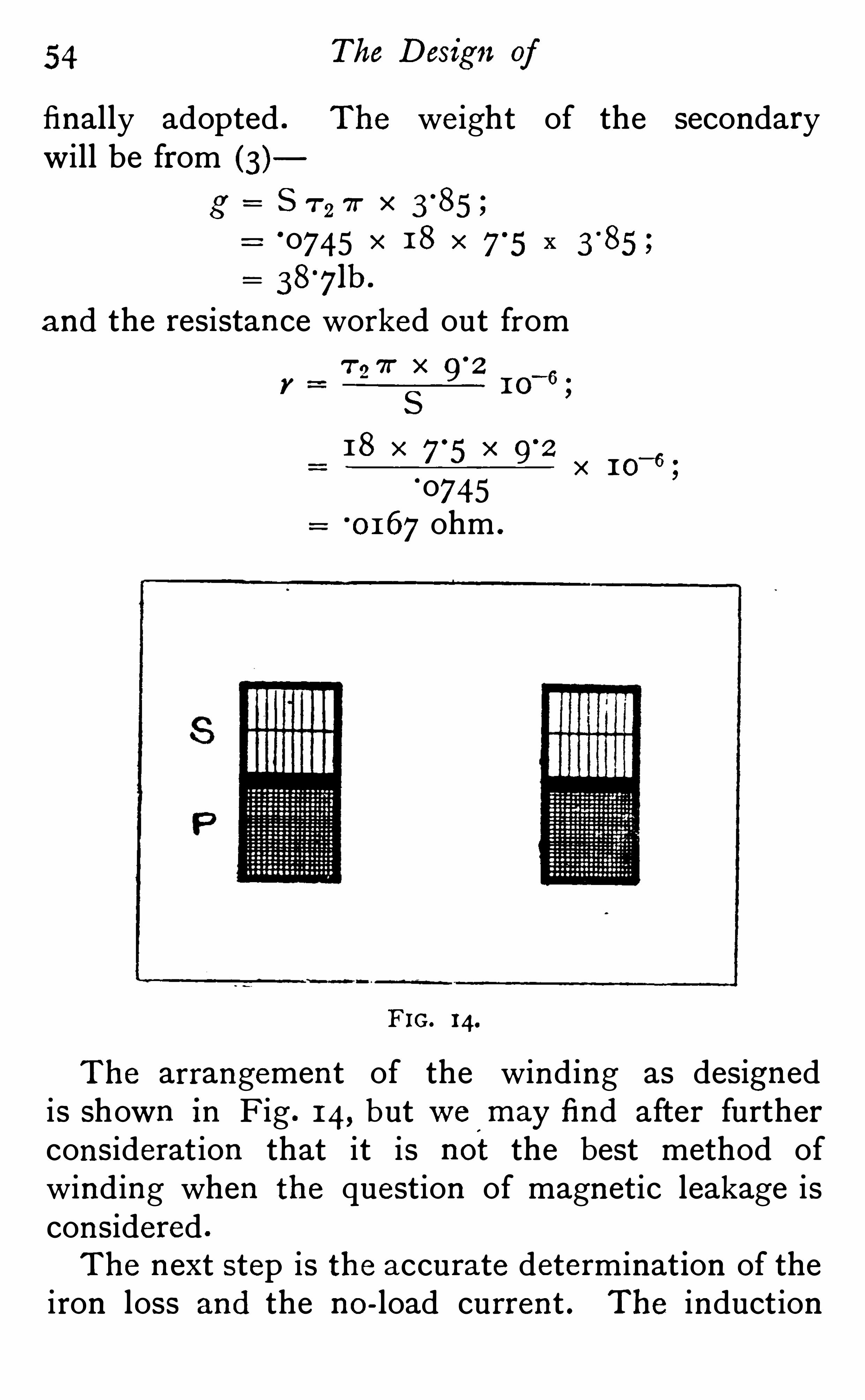
F IG. 14.
The arrangement of the winding as designedis shown in Fig . 1 4, but we
‘
m ay find after furtherconsideration that it is not the best method ofwinding when th e question of magnetic leakage isconsidered .
The next step is th e accurate determinat ion of theiron loss and the no- load current . The induction

Alterna te Current Transformers . 5 5
a ssumed at first will be a ltered , owing to the changein the number of turns . From ( 1 ) we get that
e1 F 71n 1 o
‘ s,
and now e1 and 7 , 3 5 4.
x F x 3 5 4 x'
1 00 x
X 3 5 4
The area of the core being 690 square centimetres ,“
g instead of as first assumed . At
this induction the loss per pound of iron is°
32 watt .
The total weight of iron being 5 26lb . , we get a
loss of 5 26 x°
3 2 1 68 watts , or per cent . For
this loss , at volts , a current of°
o84 ampere W l ll
be required , which we call iH , Fig . 3 .
The data for determin ing the current requ ired tomagnetise the i ron isgot from formula (2)
ilBl
,u. 7 1
1 7 6
Here l,the mean length of magnetic
path , i s 1 7 in . centimetres . The,u corres
ponding to the above induction for this iron is (fromFig . 5 ) and 7 1 3 54.
x
x 3 54 x
0-0995 .
J(°
O84)2 .
09952;
°
1 3o ampere ;
per cent . of th e full-load primary current .

5 6 The D esign of
The various details of the des ign are therefore as
followsS ix-Ki lowatt Transformer Second Design .
—Ratioof transformation , volts ; v
Core, 35m. x 36in . ; area of cross - section of iron ,
690 square centimetres .
F I 43'
2cm .
Primary : 7 1 3 5 4 ; 7: 7°
5 ft .
Conductor , 68-mil wire in sulated to 83 mils , andwound in 1 8 layers of 20 turns .
r ohms , hot ; loss 1 per cent . ; weigh t , 37 lb .
Secondary ; 7 2 1 8 ; 7 :
Conductor, tape (°6ooin . x
°
1 25 1n .) insulated to
(6 40 x°
1 65 ) wound in n ine layers of two turn s each .
r°
01 67 ohm ; loss , 1 per cent . ; weight 38'
7lb .
Losses— Iron 1 68 watts, or per cent .
Copper , primary 60 or 1 0
Copper , s econdary 60 or
Tota l 288 watts per cent .
Therefore th e efficiency at full load is
6 288 95 4 per cent .
The watts wasted at no load are 1 68 , and the
apparent watts at no load are x°
r3o= z6o.
‘
1 680
260646 °
The we ight of iron 5 26 lb ., at 4d . per 1b . 1 7 5 5 5 .
copper 7 5°
7 lb . , at 1 od . per
Therefore th e power factor will be
Total 60 1°
7 lb . 238°6s .
and per kilowatt .

A lternate Current Transformers . 5 7
The ratio of the weight of copper to weight of
iron i s °
1 44.
The iron in this tran sformer provides the greaterpart of the cooling surface , and the laminations asplaced act wel l as radiators . The total surface of
iron exposed to the a ir is square inches , and
the ends of th e copper coils , with insulation , provideabout 1 32 square inches more .
~ This gives a totalcooling surface of square inches . The wattswasted at no load are 1 68 , and at full load the totalloss is 288 watts . These figures give a mean of °
1 1 3
watt per square inch at no load , and°
1 93 watt persqare inch at full load .
As might have been expected , from the largeamount of material used , these figures are better thanthose obtained in the first des ign in spite of t heincrease in the iron loss . Bes ides this , th e platessurrounding the coils are arranged so that the laminat ions all run out to the surface . Thus the heat canbe readily dispersed by conduction . Still , in spiteof this great advantage, which accounts in some
measure for the low temperature rises found in theWestinghouse and Mordey transformers , it must beremembered that it is impossible to obtain the
temperature of the wire in the centre of the transformer . The heat generated in wires at the centrewil l mostly pas s out through the insulation to the
iron and thence to th e a ir . Hence the temperatureof the wire in the middle must be cons iderably higherthan that of the inside edges of th e iron plates . The
inside edgeswi ll again be hotter than the outside, butthe d ifference will not be so much as the iron is a good
./Q? ESE Hem0 17 T u x:

5 8 The Design of
conductor compared with the insulation on and roun dth e copper . So although the temperature on the
outs ide i s low , the copper wires in the centre m ay
get hot .The great point to be noticed in the above
results from the des ign is , that th e ratio ofweight of copper to weight of iron i s small ,(on ly This ratio is fixed by th e mechan icalarrangements of the core, but , as seen above,this method of construction has already beenmodified in order to get more iron in . The saving int he iron stamping effected by the u se of every piece ofiron stamped out will not make up for the want ofefficiency in th e transformer , and so for large s izes theproportion s given above are not adhered to . By
en larging th e windows w e are enabled to wind moreturns in both primary and secondary , and hence toreduce th e flux required . Again , by this a lterationless iron can be used , and hence the total weight andcost can both be reduced without prej udicing theefficiency . Still , the des ign worked out above wouldgive good results if better iron were used .
Another point to be noticed , is that th e powerfactor is of the same order as that obta ined in the
first des ign , where th e length of th e iron circuit w as
1 23 centimetres . The decrease in length of thepath of th e magnetic lines would give a corresponding decrease in the current required to magnetiset he iron ,
in , if th e number of turns in the primarywere th e same . In this case, however , the numberof turns in th e primary are much fewer than in the
previous design , and hence the in comes out about

60 The Design of
ened , and thus prevent any displacement of theplates .
There are several other makers
FIG. 1 5 .
FIG. 16.
sim ilar in general outline to the above, andmechan ical constructions adopted by two of themare worthy of special note . Th e Westinghousetransformer is shown in section in Figs . 1 5 and 1 6 .

A lternate Current Transformers . 61
-As will be seen , the appearance of the sect ion i s verysimilar to that of th e transformer , Fig . 1 2 , ex
cept that the windows take out a larger proportionof iron ; also th e length of this transformer
,as com
pared to its other dimension s , is shorter . The
splendid efficiency of a kilowatt transformer ofth e Westinghouse type , as measured by Dr. J.
Hopkinson and Dr . Fleming (see the l ist , page 1 1 )makes th is design of special interest . The materialused in th e core is sa id to be a special make of verysoft steel plate . Th e core plates consist of singlestampings , Fig . 1 5 , of rectangular shape , with twow indows punched out where th e wire is to be placed .
To enable these stampings to be threaded on to theco ils , the plate is cut through in two places
,from
the window out to the long edge of this rectangle , asshown by the l ines (a b), Fig . 1 5 . The cross yokes ,thus separated from the core, can now be bent back ,and the s tamping placed in position on the coils .
These cross -pieces are then straightened again, and
th e stamping embraces the coils . Alternate platesa re placed on from different s ides , so that the
j oints on one plate are covered by an
unbroken part of th e next . Th e rest of the con
struction is carried out as before , the wires beingwound on formers , and well insulated from the ironby insulating cloth and other material able to withstand the mechan ical abrasion while the core isbeing built up . When complete, the iron plates areclamped up by four bolts placed at either corner, asshown in Fig . 1 6 . Th e good quality of the iron or
steel plates used accounts in some measure for the

62 The Design of
splendid effi ciency of this transformer,but th e
genera l proportions must also be very Carefully "
designed .
The other transformer referred to is the E lwellParker , and in this case the iron circuit round eachof the windows is kept distinct . Th e coils are
F IG . 17 .
lated in the usual manner , and each s ide of the longrectangle of Copper wires thus form ed are surrounded
‘
by plates of iron , Fig . 1 7 . These plates are hollowrectangles , stamped out whole and then cut throughat one place, much in th e same manner as in th e
Westinghouse plates . This enables one s ide to bebent back , in order that th e stamping m ay be slipped
’

A lternate Current Transformers . 63. o
n o
x vi/U 6
on to the wire . The success ive plates are arrangedto break j oint as described in above for otherdesigns . Th e transformer of this make , shown in
Figs . 1 7 and 1 8 , is much shorter in proportion in
it s length than the design worked out , and as it i sto scale a rough idea of the proportion of copper . toiron can be obtained .
It will be noticed that all the makers of the general
F IG. 1 8.
type illustrated by this second des ign seem inclinedto keep th e length of the transformer down . The
object of this is that th e mean length of the coppercircuits to enclose a given area , or take a giventotal flux , is much lessened by this step . This reduct ion in th e 71 of the copper saves weight and space,both of which are va luable . Still , some makersdo not reduce the copper weight , but prefer insteadto add more turns in the space , and thus reduce the

64 The Design of
iron loss . This seems an easy method of increas ingthe efficiency , but th e magnet ic leakage is also muchincreased unless further changes in th e methods ofarranging the copper circuits are made . Thatthis is so is seen from the fact that the magneticleakage in th e Westinghouse transformer in thel ist is its worst feature . I t is per cent . , andi s the highest percentage leakage recorded by.
D r . Fleming .

CHAPTER I I I .
Third Design— In this , the last transformer to be
d esigned , we wil l make the mean lengths of th ecopper and iron circuits nearly equal . The firstdesign had a short copper circu it and a long ironcore ; then , in the second , these relat ive proport ionswere reversed and th e iron circuit was short . Now ,
the mean length of th e turn s in th e copper circu itsand the length of th e path of the magnetic lineswill be , roughly , the arithmetical means of the
respective values in th e two previous designs . Thisgives a transformer of the type used by Ferranti , inwhich a rectangle core of iron is surrounded byrectangular formers conta in ing th e copper conductors .
Assuming the core to be 9in . long by 3 in . broad ,and the length of winding formers to be about 951m ,
we can roughly estimate the weight of iron in thetransformer , Figs . 1 9 and 20 . The cross-section ofth e iron equals 85 per cent . of 27 square inches = 23
square inches , or 1 48 square centimetres . The
l ength of the iron circuit cannot be accurately

66 The D esign of
determined til l the winding has been fixed , but willbe , roughly , 28in . , so that th e volume of the iron23 x cubic inches and weighs 1 80 lbs . The
iron loss allowed is 1 5 0 watts , so that the loss per
F IG. 19.
1 5 0
1 80
losses , Fig . 4, shows that this corresponds to an
induction of about l ines per square centimetre .
The core area being 1 48 square cent imetres , hence
pound °83 5watt . Th e curve of total iron“
6 8 The D esign of
We must have an even number of turns , as twolayers will be th e most conven ient method ofa rranging the secondary strip— 44 being the nearesteven number , will do well for th e number of turnsin the secondary . The primary turns can now becalculated from
7 2x 44 x
7 11 02 1 02
865
In this type of transformer the coils are usuallywound on separate formers and s l ipped on individually . The question of which should be nearer thecore has been often discus sed , and the balance ofadvantage appears to lie in placing the secondarynext to the iron , as then th e high volt winding isfarther from th e iron , and less l ikely to leak to earth .
Also the thick wire of the secondary is wound ona smaller former , and is hence more s table . Th e
question of eddy-currents in th e copper due to leakageof magnetic lines from th e core out through thecopper has been urged as a reason for putting thethick wire outs ide . With certa in s tra ined assump
tions as to leakage and copper weight , this appearsto be a valid rea son but for th e fact that the eddycurrent losses in th e copper are so small as to benegligible in most trans formers . Assuming the
leakage to take place radially from the core , theinduction and hence the eddy current loss per un itvolume of Copper , is greater near the core . But th e
volume of copper required increases more rapidlyt han the perimeter of the winding if a constant full

A lternate Current Transformers . 691
load drop is -allowed , and so the increase of volume
varies almost with th e square of th e perimeter . Thisincrease i n volume or weight of conductor balancest h e decrease in the density of th e leakage field , andkeeps the Foucault los s constant . Hence there isno disadvantage from leakage caused by winding th ethick wire near the core . Placing , therefore , thesecondary ins ide , it is necessary to des ign it first , asits thickness will affect the perimeter of th e primary .
The clearances between th e insulating cylinder
and the iron must be s l ightly more than in the
previous des ign ,owing to th e method of core
construction used . Fig 20, shows the general outlineof the coils
,and from it th e mean perimeter of th e
secondary equals 2°
37ft . Th e tota l length of theinsulating cylinder being 951m , we shal l get about83m. for winding space . Th e section of th e tape tobe used is got from (3 )
Z 7 2 71
52 9 2
I O6;
i 60
T2 44 9 I .
s 60 x44 x 2°
3 7 x 9°
2
°
05 72 square inch .
The tape had best be wound in two layers of 22turns each , so that the insulated tape should measure
8'
5 in .
22
wound in 8 °
5 in . U n insulated the copper would beabout 3soin . broad , and to give the section must be°
1 65 in . thick . Tape (°
3 5 oin . will therefore
say ,°
385 1n . ,ln order that 22 turns may be

7 0 The Design of
be used , and the two layers will give a total depthofwinding of °
4ih .
Calculating th e res istance as in previous des ignsfor the exact section of the tape,
°
o5 77 square inch ,w e get from (3) that r
2= °
0 1 66, which , with 60
a mperes , gives j ust under th e one volt drop allowed.
The weight of copper from
g= e r a .
by substituting th e proper value for the symbolsbecomes , g
°
os77 x 44 xz3 lb .
The clearance between the outside of this secondarywinding and th e primary cylinder must be sufficientto allow th e latter to be s lipped on . The space lefti s by no means wasted , as it provides ventilation tothe wires in the centre of the coil . In fact , with atransformer so placed that these cyl inders are
vertical , th e chimney action in these air spacesbetween th e windings is most useful in cooling t hewires . This space and t h e necessary thickness ofcylinder and wire ra ises the mean perimeter of theprimary wire to about 2
°
87ft . This is the onlyremain ing unknown quan t ity in th e equat ion for thediameter of th e wire
7 1 I I°
7 5
6
the other values being a s followsi = 3 ; 1
~
1 86s ; 7r = 20 ;

Alternate Current Transformers .
SO 66-mil wire will give th e 1 per cent . loss , andit can be wound in eight complete layers of 1 00
turns and one layer of 65 turns . In between eachlayer it will be necessary to place a sheet of insulat ing material , a s there will be a difference of
potential of about 470 volts between adjacent wiresin different layers at the ends of th e coils . Th isextra insulation wil l increase the depth of thewinding to about °8 5 in . Th e resistance of thewire from (4) is
I I 7 5dz
865 x x
066 x°
o66
ohms .
The weight of conductor,from the formula
following the above , works out to 32°
7 lb . Thesecalculations complete the design of the Coppercircuits .
W ith the Ferranti system of building up th e coreand yoke, the question of winding space does not
affect the calculations so much . I t is necessaryfirst to des ign th e coils to suit th e core area allowed ,and then to get out the length of plates required toencircle these coils with ample clearance . Leavingt he actual details of construction til l later, we can ,
from Fig . 1 9 , get the mean length of the iron circuit,
which is 28°
5 in . , or centimetres . The crosssection of iron was 23 square inches , so that the exactvolume wi l l be 65 6 cubic inches , weighing 1 83 lb .
The total field , F , required when 7 2 , 44 will be

72
C .G .S . l ines , so that
The loss per pound in watts at this induction forthe iron assumed by curve Fig . 4, is 8 27 , so thatthe total iron loss 827 x 1 83 1 5 1 watts . The
watt current , iH , required to give this power at
volts ‘
075 6 ampere .
The next step is to determine the,u. current
fi lfrom
a 7 11 7 6
In this transformer al centimetres ;,u. from curve , Fig . 5 ;
865 ;
3 5 20 X
x 865 x 1 76°
0864 ampere .
Now i , th e magnetis ing or no - load current ,
°
1 1 5 ampere,which is per cent . of th e full- load primary current .
Collecting all the figures into a l ist .S ix-Ki lowatt Transformer— Third Design .
— Rat io oftransformation , volts ;
A
v 1 00
Core , 9in . x 3 in . ; area of cross -section of iron ,
1 48 square centimetres .
a F I 72°
7 cm .
Primary : 7 1 865 ; 71'
2'87ft

Alterna te Curren t Transformers . 7 3
1 00 turns per layer and one layer of 65 turn s per
‘
r ohms , hot ; 105 5 1 per cent . ; weight ,
Secondary : 7 44 ; 7 1°
Conductor°
used,tape (
°
3 5 oin . x woundin two layers of 22 turns each .
r°
01 66 ohm , hot ; loss , 1 per cent . weight , 23 lb .
Losses — Iron 1 5 1 watts per cent .Copper , primary 60
Copper, secondary 60 1°
o
27 1 watts per cent .
The efficiency at full load being
95 7 per cent .
Magnetising current per cent . , so that theload factor , or ratio of true watts to apparent wattson open circuit , equals 6 5 7 .
The weight of iron 1 83 lb . at 4d . per lb .2 61 5 .
copper 5 5°
7 lb . at 1 od . per lb .
Tota l 238°
7 lb . 1 07°
5 s .
Which gives 39°
8lb . and 1 8s . per kilowatt output .The ratio of weight of copper to weight of iron
1 83
The effective cooling surface of this transformer isdifficult to estimate correctly , and comparisons made
F
equa ls

74 The Design of
on the basis of th e watts wasted per square inch totalexternal surface will not afford a true idea of th eheating limits . This is due to th e number ofventilation spaces runn ing right through both th e
copper and iron circuits , which byeffects greatly ass ist the external surfasurface which is exposed externally amounts to on ly
F1G. 2 1 .
7 50 square inches , and hence the watts per square
inch work out to Z; at full load , and to
1 5 1 ‘
201 at no load .
7 5 0
The method of construct ion of the iron circuit 15explained in Fig. 2 1 . In this transformer , as de

76 The D esign of
mechanical parts , form complete circuits embracingparts of the induction through th e iron core . Otherwise secondary currents are induced , which addenormous ly to th e losses .
The only remain ing type which requires distincttreatment is th e Hedgehog , an open - circuit transformer introduced by Messrs . Swinburne and Co .
In this case th e iron circuit is not closed ,whole of th e induction has to return from one
F IG. 22 .
of the core to the other by the The advantageclaimed for this transformer was that it had less ironloss than any ordinary closed -circuit transformer .
This has been proved to be a fallacy by Dr . Fleming’smeasurements on a three and on a s ix kilowatt transformer , both of which had no-load losses as great asmost closed -core types . He also showed that themanufacturers have been mis led by a wattmeterwhich

A lternate Current Transformers . 77
gave low power reading on inductive circuits . The
grounds of the statement that there is less iron lossappears feasible at first s ight . Suppose the transformer last des igned w as taken , Fig . 2 1 , and th e
iron yokes were cut away j ust after th e b end . Thiswould reduce th e weight of iron to one-half itsformer va lue . Then ,
if t he same induction wereused , the iron loss should be halved . Bu t for the
fact that th e core is rectangular, w e should nowhave a Hedgehog .
Figs . 22 and 23 , shows th e con struction of thismake of transformer . Th e core cons ists of thin ironwire stiffened by a gunmeta l casting, which formsthe support for all attachments . The iron wire islaid in between th e flanges of this , and then boundtightly up with twine . Wooden flanges to supportthe copper wires are s l ipped on over the core . The
winding of th e coils is carried out much in the same
way as described in other cases but for th e fact thatthey are wound in si tu , and that two sets of secondarywinding are used , one each side of th e primary .
Th e ends of the wire core are spread out after“
th e wooden flanges have been passed over them .
Th e object of th is spreading is to decrease the
magnetic leakage along th e core as much asposs ible .
The first abnorma l poin t requiring not i ce 18 the
large no-load current required . Thus , in the s ix
kilowatt tested by Dr . Fleming , th e no - load currentwas 47 5 per cent . of th e current required to furn ishs ix kilowatts at th e norma l voltage of th e primary .
The actua l loss at no load was per cent .,so


Alternate Current Transformers . 79
that the current required to m agneti se the iron , in ,
i s J 47°
52
per cent ., and
i ), 46 6
Now,in th e c losed-circuit tran sformers designed
above , this ratio was s lightly greater than un ity , andin many transformers with superior brands of ironit falls below un ity . The high va lue of in in the
Hedgehog transformer is due to th e a ir resistance inthe return path of the magnetic l ines .
Again , it will be noticed that the iron los s was
per cent . of th e tota l ou tput , whereas if thetransformer , Fig . 2 1 , had it s iron reduced by cuttingaway the yokes , th e loss would be on ly per centThis , of course, m ay be explained by assuming thatin the Hedgehog transformer th e iron is worked ata much higher induction , but it is l ikely to be due tocauses peculiar to th e type . Th e l ines of force inthis transformer are supposed to flow a long th e fulllength of th e iron and then to return by th e a ir , and
th e turn ing back of th e wire core at th e ends doesmuch to en sure th is . Still , l ines of force do leakout before the ends are reached to a much greaterdegree than occurs in any closed -c ircuit transformer .
Th e result i s , that to mainta in th e same E M. .F in
th e wires , th e total flux in the central sections hasto be increased to make up for the smaller flux cuttingth e end conductors . Although th e mean inductionm ay be the same , the higher den sity in the centrewill increase th e tota l iron loss more than the
diminution of den s ity at th e ends reduces it . Then ,
80 The Design of
too , the leakage l ines have to pass through the
copper, and in so doing may cause eddy currents toan appreciable amount . These causes are l ikely toaccount for the no -load loss being considerably higherthanwould be expected from th e quant ity of iron used .
The large curren t at no load is th e great d isadvantage of this type , because a lthough wattless inthe transformer , it causes losses in all th e conductors .
Also , it heats th e a lternator armatures as much as i fthe apparent power were being actually supplied .
Thus , i f a station were equipped solely w ith Hedgehogs , at least 40 per cent . of th e plantWould have to berun cont inuously . The method suggested of overcoming this disadvantage is that of using conden sers inparallel with th e trans formers to supply this largecurrent . Th e dielectri c losses in th e conden sersthen have to be cons idered , and they are far fromnegligible . E ven i f th e Open circuit have the advantage cla imed of l ittle or no load loss , i t does not
follow that it is better than a closed circuit ; for i ftwo such transformers are taken and placed side byside , the iron at th e ends would need a very s lightincrease of length in order to complete the ironcircuit through th e two . Th e result is a closedcircuit transformer of twice th e output and abouttwice the iron loss . This loss will be reduced belowth e sum of the two individua l transformer losses ,owing to th e un iformity of induction resulting fromthe completion of th e iron circuit . Th e current atno load would of course be reduced to the normalamount required by a power factor of, say , 70 to 80
per cent .

A lternate Current Transformers . 8 1
Large transformers are expected to bemore efficientt han small ones , but still the combination thus madewill show at once th e advantage of having a closedc ore .
Magnetic Leakage of Transformers .
— This brancho f the subj ect is one that cannot be satisfactorilyt reated by calculation alone , and even when aidedby previous experiments it is not easy to predictaccurately the leakage effects in a new des ign .
When a transformer i s working a full load , the internalreactions cause fewer l ines of force to pass throught he secondary than through th e pr imary , and hencew e find a larger drop of volts than can be accountedfor by loss In th e copper . I t is usua l to deduct th eknown C R losses , and to call the rema in ing drop in
pressure magnetic leakage . When a transformer
is working l ight the pr imary suppl ies the currentneces sary to magnetise the core and th e secondaryh as no curren t in it , hence th e action is s imple and
t here is.
no differentia l magnet ising effect . Now atfull load in the third design th e primary current hasincreased to 26 5 t imes it s previous value , and we
have th e sec’
ondary current oppos ing the magnetis ingforce of the primary . At no load , th e magnetisingforce j ust in s ide th e primary due to in ampere)
in 7
l
and l th e length of the coil .
where 7 the turn s per coil ,
0864 x 865 x23 6
So that the induction in th e a ir would be very
in C .G .S . measure .

82 The Design of
small — compared to that in th e iron . At
full load the current rises to three amperes ; so th emagnetising force in the air space inside th eprimary will now be
3 x 865 x
FIG . 24.
This will give an induction of 1 95 l ines per cent imetre , which ,
when multiplied by the area , gives aleakage flux which is appreciable .
Th e action is not confined to the actual spacebetween the windings , but extends into the wire .
Thus , in Fig . 24 the values of H are plotted over

The D esign of
valuable . I t is better in working out trans formers.t o obtain th e number of ampere-turn s per givenlength of leakage path , and then by comparisonw ith previous experiments to determine th e probable leakage effects . When measuring th e magnetic drop , great care must be taken that the
c ircuit used for th e load h as neither induction nor
capacity in it . O therw ise th e results will be p rac ti ~
c ally useless . V ery little capac ity will completelyannul th e drop and , on th e other hand , inductionincreases it .
In connection with leakage it must be clearlyremembered that it is on ly alteration in magneticflux due to th e secondary current that causes badregulation . Leakage of th e induction in the corea cross to th e yokes , such as i s found in all magneticcircuits , h as no harmful effect on th e regulat ion .
Thus th e Hedgehog transformer virtua l ly h as the
return path of th e magnetic lines as leakage , and
yet it regulates a s wel l or better than many closedcircuits . This is due to th e fact that t h e differencesb etween the magnetis ing force of t h e primary at no
load to its value at full load is nearly 3 to 1 insteadof 26 to 1 , as in the tran sformer above . Thisleakage, which does not affect th e regulation , m ay ,
however, be very harmful in caus ing eddy currentsin both iron and copper , and a Hedgehog transformer made with a core of iron plates would showthis at once by giving a larger iron loss than withthe wire core .
Alteration of Efii cieney w i th F requency .
—The select ion of th e most economical frequency for alternate

Alternate Current Transformers . 85
current working from supply stations is influencedby so many different con s ideration s that th e presen twant of un iformity in this respect can hardly be a
matter for surprise . I t is m ost im portant that eachcompany us ing the a lternate - current system shouldarrange all their generating plant to work at the
same number of cycles per second . If th e prime
movers are suitable , th e a lternators can then be run
in parallel with each other , and even if t h e enginewill not allow of para llel runn ing , this un iformity inth e frequency given by th e different a lternators inth e same station is advantageous . B eyond this th ematter has been largely left in the hands of th emanufacturers . So we find that in America the highfrequency of 1 3 3 periods per second has been extens ively used because a large manufacturing companyadopted it as their standard . In E ngland
, th e praotice isto u se generally frequenc ies between 7 5 and 1 00,whereas on th e Continent m u ch lower values havebeen successfully adopted . It is out of th e range ofthe present chapters to con s ider the whole groundsfor and aga in st either extreme in t h e adoption of at
standard frequency . Roughly, th e higher va lues
tend to slightly reduce th e first cost of th e generating plant , and th e u se of motors is as yet
on ly commercially poss ible where low frequenciesare used . Whichever may be un iversally moreeconomical , the fact remains that transformershave to be used , and it is the effect on th e
economy of the transformer that we have to
consider .
From equation (1 ) th e potent ial difference , as

8 6 The Design of
measured by a Cardew voltmeter , at th e terminalso f a transformer on open circuit is
e F 7 71 1 0— 8
,
and F , th e total flux ,m ay be written 38 a where
equals the max imum induction , and a equals th ecross-section of th e iron core . Hence ,
e(
E a r n 1 0— 8
With a transformer having a certa in transformingratio , say , volts , th e voltage , e, requiredon th e secondary wil l be the same whatever the
frequency of the alternating- current supply . Thisensures that e sha l l be a con stant quantity howeverth e frequency may vary on different supply mains .
We may therefore con s ider e as constant , and the
quantit ies a and 7 ou th e other s ide are also con
s tant s for any given transformer . Hence,if n
changes , there must be an inverse change in“
18 tokeep th e up to th e same va lue, or , in otherwords , n 18 1m, where 181 u 1 are the new valuesof the induction and frequency respectively . Hence ,in th e transformers des igned above for 1 00
’ “v the
induction required would be doubled if the frequencywere dropped to 5 0
Av This alteration in induc
tion alters the value of the iron losses , and henceaffects th e effi ciency of th e transformer .
The subj ect of th e loss in iron wire and plateswhen subjected to a magnet ising force which varieshas been a source of many investigations of lateyears . The conclusions arrived at by th e many ableexperimenters on this subj ect are : first , that th e
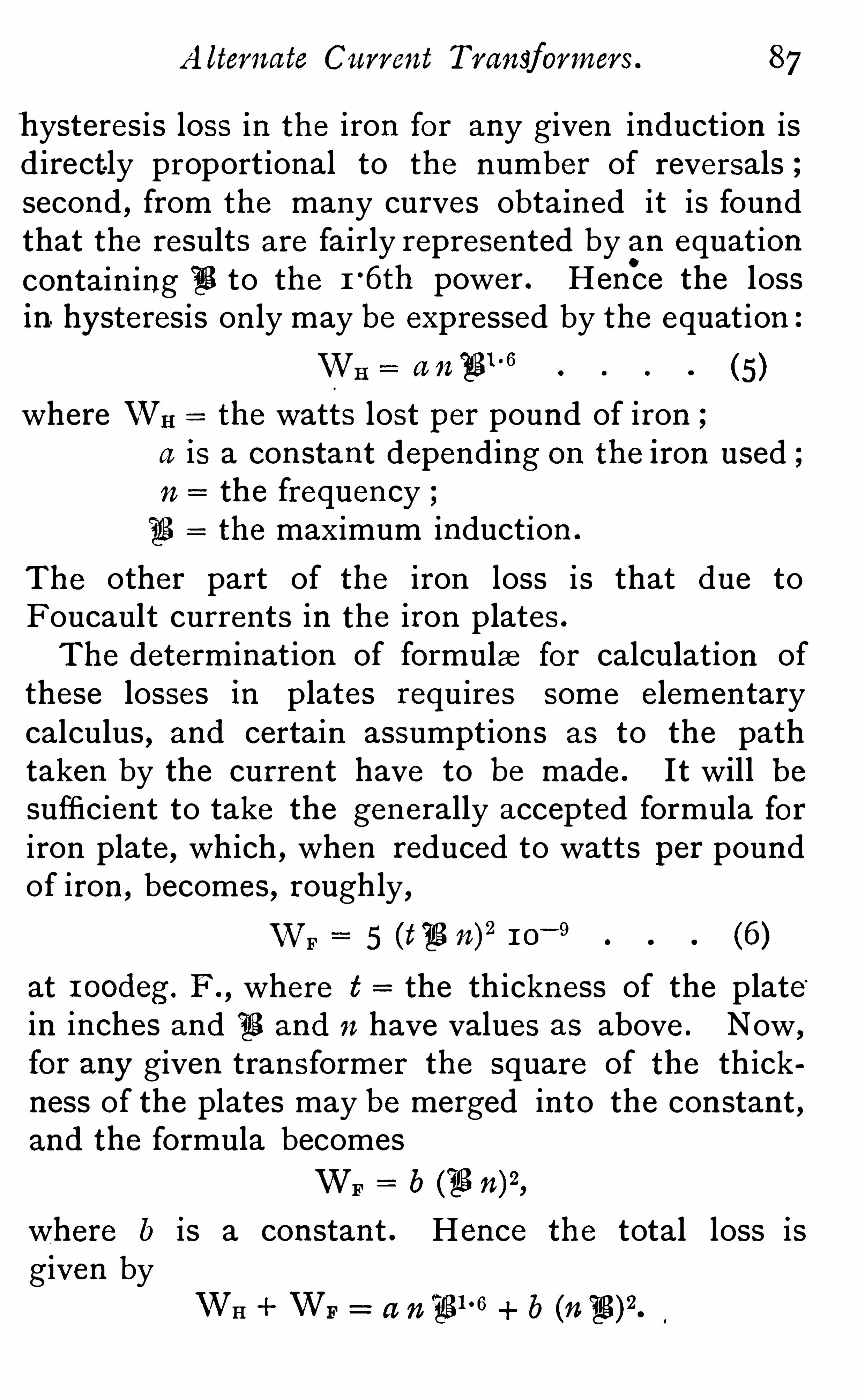
A lterna te Current Transformers . 87
h ysteresis loss in th e iron for any given induction isdirect ly proportional to th e number of reversalssecond , from the many curves obtained it is foundthat the results are fairly represented by an equation
contain ing(
Q to th e 1°6th power . Hence the loss
in. hysteresis on ly may be expressed by the equation
WH a n'
figl ‘ fi
(5 )
where VVH the watts lost per pound of irona is a constant depending on the iron used ;n the frequency
313 the maximum induction .
The other part of the iron loss is that due toFoucault currents in th e iron plates .
The determination of formula for calculation ofthese losses in plates requires some elementarycalculus , and certain assumptions as to the pathtaken by the curren t have to be made . I t will besufficient to take the generally accepted formula foriron plate, which , when reduced to watts per poundof iron , becomes , roughly ,
WF 5 (133 n)2
(6)
at 1 oodeg . F . , where t = the thickness of the plate“
in inches and ‘
E and n have values as above . Now ,
for any given transformer the square of the thickness of the plates may be merged into the constant ,and the formula becomes
b (lg 7 02,
where b is a constant . Hence th e total loss isg iven by
WH + WF= a n
°
4281°6+ b (n iBV.

88 The D esign of
As 71 occurs in different powers in th e twoon th e r ight -hand s ide of this equat ion
,
readily seen that any curve drawn for th e totaliron losses for a given frequency cannot be used at
any other frequency . I t is , however , quite poss ibleby careful experiments to verify t h e equation givenabove . This can best be done by taking powerreadings of th e iron losses when th e frequency i svaried very considerably . Then the differen t set ofresults can be ana lysed by s im ple algebra . This canbe more readily donewith plates of greater thicknessthan those used in ordinary work
,as in that ca se
th e express ion for th e eddy curren ts is a larger proportion of th e total loss . Th e approx imate truth ofthis formula and th e corresponding expression for
the eddy- current loss per pound of iron beingestabl ished , w e can proceed to divide the curve ofiron losses , Fig . 4 , into it s two components . To dothis , th e loss in foucault currents in watts per poundfor inductions varying from
“
E tomust be calculated from and th e figures obtainedwhen subtracted from th e ordinates of curve, Fig . 4,
leave th e hysteresis loss per pound at 1 00 cycles per
second . Thus at 33 for 1 0 -mil plates wehave
F 5 1 0
5 x x x x
5 x x x 1 0— 9
°
1 8o watt per pound .
Now the ordinate on Curve 4 when fi = 6,ooois Therefore th e hysteres is loss alone is
°
1 8 watts per pound of iron .

A lternate Current Transformers . 89
Doing this for all the points , and plott ing theresults in a curve as before , w e obtain F ig. 25 ,
which gives th e loss per pound of iron due tohysteresis on ly , at 1 00 v
. From this the lossesat other frequencies can be obtained
.
by simpleproport ion . I t will be found on tr ial that thecurve thus obtained is not quite in un iformity withthe equat ion of it to th e 1
°
6th power . This is dueto some qualities of the iron from which the or iginalresults were obtained . To explain fully th e methodof working with this curve it will be well to takethe design No . 1 and to calculate th e iron losses forthat transformer when working at frequencies of
5 0, 7 5 , 1 00, and 1 30 respectively .
We have from the table of resul ts that for1 00 = 3 , 5 8o at the normal voltage ; now
u 3 u 1 E1 , so that the value of
£ 1 for u 1 5 0 is1 00
In the same way for n, 7 5
x 1 00
7 5
and at u1
1 30, $1
We will in this case tabulate the results , as errorscan then eas ily be seen and avoided . The fact thatthe hysteres is loss is directly proportional to thefrequency now enables us to determine the totalhysteresis , loss in each of the above cases . Thusat
(
Q the loss per pound at 1 00 v is ,G

90
from Fig . 25 , watts per pound . Thereforeloss at 5 0 v in 1 72
°
5 lb . will be
I 7Z‘
S X 5 01 68 watts .
1 00
TABLE OF IRON LOSSES AND NO-LOAD CU RRENTS FOR SHELLTYPE SIx -K ILOWATT TRANSFORMER (DES IGN 1 )AT D IFFERENTFREQU ENCIES .
Frequency.
Hysteresis wattsFoucault wattsTotal loss
Iron loss per cent .i per cent .Power factor
In the same way for “
E and n 7 5 ,
I 7 Z'
S X 7 51 46 watts .
1 00
Th e rest of the values of WH calculated in the same
way are 1 3 3 8 for n 1 00, and 1 24 watts for n = 1 30 .
The Foucault loss is got from the formula (6)— al e ,
watts per pound 5 (t E n)21 0
— 9.
In this transformer I o-mil plates were used , andthe iron weighed 1 72
°
5 lb .
Hence , WF x 5 x x x x 1 0— 9
.
1 1 watts at 5 0 frequency .
But we saw above that E n was always a constant

92 The Design of
;u for each induction can be at once taken from thef.
curve Fig . 5 . Then in from (2) As
four values have to be calculated and the
l
X
may conven iently be worked out separately .
In this transformer , l, th e mean length of the ironc ircuit was 1 23 cm . and 7 1
right-hand side , is common to all cases , it
lth f 68 ;ere ore
7 1X
04
(
gX 0 68 .
M4
Thus at n 5 0,(
Q and,u
68x 04
1 27 ampere .
The rest can be worked out in exactly the same way .
The values of iH are obtained by dividing the totaliron loss by th e voltage on the pr imary winding,which in this case was
The magnetising current i Ji g2 in
2, so in the
first case $ 0892x
°
1 272
°
1 5 5 ampere .
Completing th e other values in the same way, itwill then be better for reference to add two morel ines
,showing the iron loss and magnetising current

A lternate Current Transformers . 93
r espectively in percentages of the full-load values .
The ratio of these two gives the power factor , whichwill be seen to fall with the frequency . This is notalways so , but depends largely on th e shape of the
,u. curve of th e iron used .
The general conclus ion s from this investigationare brieflyas follows When the frequency at whichthe transformer is used is decreased , the loss in ironis increased , and there is consequently a fall in theefficiency of th e transformer. ( I t must be remembered when cons idering the loss in th e iron of atransformer , that although th e loss may be a com
parat ively small percentage of the maximum output ,it is a large percentage of the average load . Thus ,while an increase of 25 per cent . from to
per cent .—does not appear much , it may make
the difference between profit and no profit in th ecentral-station accounts .) Al so th e larger iron losswill increase the final temperature of the transformer . So , for low frequencies , more coolingsurface should be provided . In other words , a
larger transformer is required . This , of course ,will raise th e cost of the instrument for a givenoutput . On the other hand , a transformer des ignedto have a good efficiency at a low frequency can be
used more economically at higher frequencies , butthe cost of manufacture will then be the prohibitivefactor .
Quali ty of I ron .— This is the indeterminate quantity
wh ich causes uncertainty in the manufacture oftransformers . Every batch of iron received shouldbe kept separate, and the test of the transformers

94 The D esign of
made from it then give a ready check on any fallingoff in th e qual ity . The curves given (Figs . 4 and
which have been used in a ll the des igns above , weretaken from a transformer actually made . Th e ironw as a better quality than th e average brands ofplate , but was by no mean s th e best that can be
obtained . With careful selection , iron can be foundwith which the losses per pound come out qui te
30 per cent . below those given in Curve 4 . I t is in
the permeability curve that th e greater difference isnoted with these superior qua l ities of iron . Thiscurve , then , rises much more rapidly at low inductions , and th e permeabil ity throughout may be some
80 per cent . higher than th e values given in Curve 5 .
The higher permeability reduces th e current re
quired to magnetise th e iron , and consequently thepower factor i s increased . On referring to Dr
Fleming ’
s l ist of tests , it will be seen that in one
case h e obta ined a power factor as high as '
92 . A
special brand of mild s teel i s said to be used in thistransformer , which must have a very high per
meability to account for such a power factor .
Transformers for D ifferent Methods of Supply — Th e
transformers used in l ighting individual houses are
very seldom worked at full load , and th e averageload is so small that th e heating effect of the curren tin the copper circuit m ay be almost neglected .
The transformer should,of course, be able to
stand th e full current for some hours withoutundue rise of temperature . The all-day efficiencyis then fixed by the iron loss
, and the coppermight be reduced to save first cost i f the reduc

A lternate Current Transformers . 95
t ion 1n section did not also affect th e regulat ion . The sub -station system of supply isnow coming into more general u se . In thissystem the consumers are connected on to a lowtension network
,which is fed at different places by
transformers in sub -stations . In this way , even ift he Whole of the transformers are left continuouslyon the mains , a much higher load factor is obtained ,owing to the different classes of buildings suppl ied .
That is to say , the average load is a larger proport ion of the maximum load , and hence the transformer i s worked more economically . To stillfurther increase the economy , arrangements are
made for reducing the number of transformers inconnection with the main as the load dimin ishes .
So in these transformers and in those used in powertransmission on a large scale , th e watts wasted int he copper form a good proportion of th e total 105 5 .
AS the heat generated in th e copper is l iable to hurtth e insulation ,
it is advisable in the large transformers used for central -station work to keep thepercentage loss in the copper lower than in smalltransformers for separate in stallation work .
THE END .


Th e E lec t r i ca l E ngin eerW ITH wnrcn I S INCORPORATED
E LE C T R IC LIGHT .
E d i t e d b y C . H . W . B I G G S ,
Ass isted by Mess rs . H . SWAN , F . B . LEA , and A . WILLBOND.
“ THE ELECTRICAL ENG INEER claims to be the most pract ical
and the earl ies t -informed paper on all quest ions relat ing to
Electric Light ing , and espec ially Mun icipal Light ing , as well ason all that relates to the D istr ibut ion and Applicat ion of E lect ricPower to all purposes . This paper was the first to make Eng lishreaders acquain ted with the three-phase system of d istr ibut ion ,the construct ion of incandescent lamps , the construct ion of
a lternate-current t ransformers , and has fully descr ibed and
il lust rated the var ious sys tems of pract ically laying mains .
Every effort is made to keep readers fully acquainted with all
progress in electr ical mat ters .
I t is the beat t echn ica l paper for young elect r ica l eng ineers .
I t a ims at and succeeds in g iving early and accurate informat ionabout all that concerns t he indust ry , and is absolutely free fromany out s ide con trol .
I t is an excellent advert is ing med ium .
Every Friday. P rice Th reepence.
139-140, SALISBURY COURT,FLEET STREET, E C.

PRACTICAL ELECTRICAL ENGINEERING.— Being
a complete treatise on th e Construction and
Management of E lectrical Apparatu s as used inE lectric Lighting and the E lectr ic TransmissionOf Power . 2Yols . Imp. Quarto.
BY VARIOUS AUTHORS .
Wi th many Hundreds of I llustra tions. PRI CE £02 23 . 0d .
Among th e informat ion collect ed in and wr it ten specially forthese volumes
,are complete monographs by
MR. G ISBERT KAPP , M . I n st . C .E . on Dynamos , giving th e
pr in cip les on which th e con st ruct ion of these mach ines isfounded , and a vas t amount of new informat ion as to th e
con st ruct ive deta i ls .
MR. ANTHONY RECKENZAUN,M . In st . E .E . cons iders th e whole
ques t ion of E lectr ic t ract ion on Ra i lways and Tramways ,descr ibing th e most recen t pract ice and giving exhaust ivedetai ls not on ly of th e mechan ism , bu t of pract ica l cons iderat ion s wh ich are of the utmost commerc ial impor tance.
MR. 0. CAP ITO, M . In st . E .E . deals with steam— and con s idersth e theory— as wel l as th e pract ical construct ion of boi lersand engines
,more especial ly in connect ion with E lectr ic
l ight ing and t ran sm is s ion Of power . This sect ion alone cont ains no less than 37 1 i l lust rat ions .
MR. HAMILTON K ILGOUR cons ider s carefully th e theory of E lect r ical dist r ibut ion upon which depends th e r ight proport ion ingof ma ins in order to secure econom ica l d ist r ibut ion . Otherm en have collected a comp lete descr ipt ion of th e var ioussystems pract ica lly appl ied
,th e mater ials used and methods
of construct ion .
Th e above form bu t a port ion Of these volumes , but shoul dprove Of th e utmost value to every one wh o professes to be an
E lectrical Engineer .

DYNAMOS Cont inu ed .
CHAPTER VII I .— Electromotive Force
Armature. Winding. Bi -polar Winding. Multipolarlel Winding. Mult ipolar Series Winding. Multipolar Seriesand Parallel Winding.
CHAPTER IX .—Open -Coil Armatures. The Brush Armature. Th e .
Thomson -Houston Armature.
CHAPTER X .— Fie1dMagnets. Two-Pole‘
Fields . Multipolar Fields.
Weight of Fields . Determ ination of Exciting Power. Predetermination of Characteristics .
CHAPTER XI .- S tatic and Dynamic Electromotive Force.
“
COTEmutation of Current . Armature Back Ampere ~Tu rns. Dynamic Characteristic. Armature Cross Ampere-Turns . Sparkless Collection .
CHAPTER X I I .— Influence of Linear Dimensions on th e OutputVery Small Dynamos. Critica l Conditions. Large Dynamos.
Limits of Output . Advantage of Multipolar Dynamos.
CHAPTER XI I I .- Loss of Power in Dyn amos. Eddy Currents in .
Pole-Pieces . Eddy Curren ts in External Conductors. EddyCurrents in th e Armature Core. Eddy Currents in the
Interior of Ring Armatures . Experimental Determination of
Losses.
CHAPTER X IV .—Examples of Dynamos. Ronald Scott ’s Dynamo .
Johnson and Ph illips’s Dynamo . Oerlikon Dynamo . O ther
Dynamos .
CHAPTER XV.— Elementary Alternator. Measurement of Electro
motive Force. Fawcus and Cowan Dynamo . ElectromotiveForce of Alternators. Self-Induction in Armatures of Alter r
nators . Clock Diagram. Power in Alternating-CurrentCircuit . Conditions for Maximum Power. Application to
Motors.
CHAPTER XV I .— Working Conditions . Effect of Self-Induction ,
Effect of Capacity. Two Alternators Working on SameCircuit . Armature Reactio’n . Conditions ofStabih ty. Genera lConclusions.
CHAPTER XVI I . - Elementary Transformer. Shell and Core Type.
Effect of Leakage. Open -Circuit Current . Working D ia
grams .
CHAPTER XVII I .— Examples of Alternators. The Siemens Alter
nator. The Ferran t i Alternator. Johnson and Ph illips’
s
Alternator. The Electric Construct ion Corporation’s Alter
nator. The Gu lcher Company’s Alternator. The Mordey“
A lternator. The KingdomAlternator.
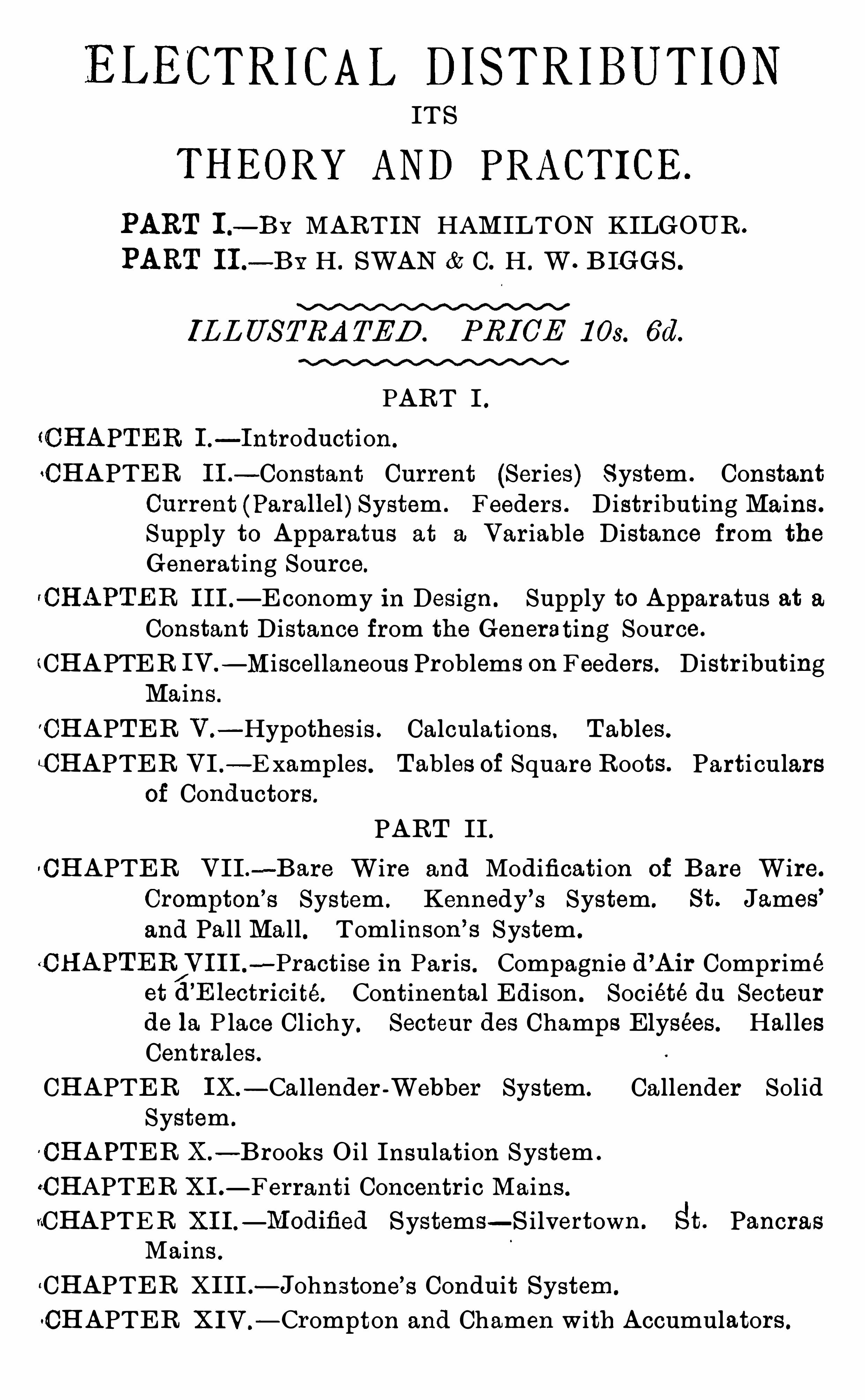
ELECTRICAL DISTRIBUTIONITS
THEORY AND PRACTICE.
PART I .
— B Y MARTIN HAMILTON KILGOUR .
PART 11 .
— B Y H . SWAN C. H . W . BIGGS .
ILLUSTRATED . PRI CE 1 03 . 6d.
PART I .tCHAPTER I .
— I n troduct ion .
CHAPTER 11 .— Con stan t Curren t (Ser ies) System . Con stan t
Cu rrent (Parallel) System . Feeder s . D ist r ibut ing Ma ins .
Supply to Apparatus at a Var iable D istan ce from th e
Generat ing Source.
fCHAPTER I I I .— E conomy in Des ign . Supply to Apparatus at a
Con stan t D istan ce from th e Generat ing Source.
(CHAPTER IV .
— Miscellaneous Problems on Feeders . D istr ibut ingMa in s .
CHAPTER V .— Hypothes is . Ca lculat ions , Tables .
CHAPTER VI .
—E xamp les . Tables of Square Root s . Part icularsof Conductors .
PART II .CHAPTER VII . —Bare Wire and Modificat ion of Bare Wire.
Crompton’
s Sys tem . Kennedy ’s System. St . James ’
and Pa ll Ma ll . Toml inson ’s System .
(CHAPTER/V I I I r —Pract ise in Par is . Compagn ie d ’Air Compr imé
et d’
E lect r ici té. Con t in en ta l Ed ison . Soc iété da Secteurde la P lace Cl ichy . Secteur des Champs Elysees . Hal lesCen t ra les .
CHAPTER IX.— Ca llender -Webber Sys tem. Callender Sol id
System .
CHAPTER X .— Brooks O i l In sulat ion System .
CHAPTER X I .— Ferran t i Concen tr ic Ma in s .
"CHAPTER XI I .— Modified Systems— S i lvert own . a. Pancras
Ma ins .
“CHAPTER XI II .— John s tone’s Conduit System .
CHAPTER X IV .
— Crompt on and Chamen with Accumulators .

ELECTR I C TRA CT I ON
A . RECKENZAUN,
I L L U S T R A T E D .P R I C E 1 0 5 . 6 d
This i s th e firs t ser ious at tempt to con s ol idate and systemat iseth e in format ion of an impor tan t subjec t . Mr . Reckenzaun
’s
experience i s of th e longest and w idest , and this book deals ri otonly with th e scien t ific and pract ica l problems m et with in tract ionwork , bu t en ters somewhat in to th e financia l aspect Of th e
ques t ion .
CHAPTER I .—E ar1y H is tory . Magnet ic Fields. Torque . Motor
Effi c iency . In sulat ion Res istance. Brake Test s . E lectr i
cal Hor se-Power .
CHAPTER 11 .— Tract ion . H igh Pressure. Curren t , Stopp ing
and Start ing . Curren t Runn ing . Energy U sed .
CHAPTER I I I .— Advan tages of Two Motors on Each Car .
Ca lculat ion s for Armatures. Construct ive Deta i ls for '
Mot or s . Types of Tramcar Motors . Method of Su spen
s ion . Brushes and Brush -holders Sw i t ches and SpeedRegulat in g Devices . Motor Trucks . Importan t Po in t sin Tramcar Mot or s . Gear less Motors . Mechan ica lTransm i ss ion between Motor and Axle.
CHAPTER IV.— Descr ipt ion of Pr in c ipa l Systems of Overhead
and Un derground Con struct ion used in E lectr ic Tract ion .
Poles . Trolleys and Trolley W ire . Overhead CurveCon struct ion . Pract ica l Hin t s on Overhead Construct ion .
In sul ator s used in E lect r ic Ra i lway Work . Sw itchboards .
L ightn ing Arres ters and Cu t -Out s .
CHAPTER VQ
— Secondary Bat ter ies . Weight and EfficiencyDeter i orat ion .
CHAPTER VI . Por trush , Bessbrook -Newry , City and SouthLondon Ra i lways . Cen t ra l London Rai lway , B lackpool ,Budapes t
,Leeds
,and Halle E lect r ic Tramways , West
E nd Ra i lway , Boston .
CHAPTER VII .— Resume ofWr it ings and Express ion s of Prom r
incu t E lectr ical Engineers on E lect r ic Tract ion .
CHAPTER VIII.— Detai ls ofWorking Expen ses .

LJ . T. NIBLETT .
I LLUSTRATED. PRI CE 28 . 6d .
Th is i s a t reat ise on th e App li cat ion,Method Of Construct ion ,
and th e Managemen t of Por table Secondary Bat ter ies .
INTRODUCTION. —A br ief résumé of E lect r ica l D iscovery .
PART I .—Portat ive E lect r ic ity in M in ing Operat ion s
,descr ibing
some of th e Lamps used , and In st rumen t s for th e
Detect ion of Dangerous Gases .
Safety E lect r ic Hand -lamps for Domest ic Purposes , forCus toms ’ Officers , for Meter In spector s
,and for Firemen .
Portat ive E lectr ic ity for Domest ic Pu rposes , forRead ing ,for Dr iving Motors , for S ter i l is ing Water .
App licat ion to Medica l and Sc ien t ific Purposes .
Uses for M i litary Purposes , for Lan d Work , At Sea .
Uses for L ight ing Vehicles , Rai lway Carr iages , Omn ibuses
,Tramcars , Broughams , Cycles .
Tract ion by mean s Of Portat ive E lectr ic ity.
App l icat ion s to Decorat ive Purposes,for D inner Tables
,
Shop Win dows,Founta in s , Jewel lery , on th e Stage
,
Persona l Adornmen t .
PART 11 .— Secondary Cells , P la
'
n t é’s,Crompton -Howel l , Epstein ,
D . P Faure,E . P . S .
,L ithanode
.
,P itkin , B r istOl. Types
of Secondary Cel l. Niblett ’s Sol id Ce ll .
PART I I I .— The Man agement of Portable Apparatus for stor ing
E lectr ica l Energy. Methods of developing E lectr icalEnergy. Thermopi les . Pr imary Bat ter ies. ChargingInst ruct ion s .
Th e Charging In struct ion s are very comp lete, and should be of
immense serv ice to those who u se sma ll Portable Cel ls .

POPULAR ELECTRIC LIGHTING.
CAPTAIN E . IRONS IDE BAX.
s x x x x x xx x x x x s x x x s xx s x
I L L U S T R A T E D , P R I C E 2 5 .
CHAPTER I .— Advan tages of th e E lectr ic L ight .
CHAPTER 1 1 .
— Source of Supply . H igh and Low Tension .
Con t inuous and Alternat ing Curren t . S torage Bat ter ies .
E lectromot ive Force. Volt . Tran sformers . D istan ceof Generat ing Stat ion from Con sumer ’
s House. Numberof Stat ion s Worked by Company .
CHAPTER III . —S t reet Ma in s . Bran ches La id for Consumers .
Con sumers L iving in Flat s . Con sumer s beyond Twen tyYards from a Main . Cost of Ma in s in Pr ivate Grounds .
CHAPTER IV.— Number and Candle-Power of Lamps Required
for Rooms . Incandescent Lamps . Not ificat ion of Ad
d it ional Lamps to be given to Supp ly Company . Wir ingof Houses . Cheap Wir ing to be Avoided. In sulat ingMater ia l . Leakage. Switches . E conomy Effected byArrangemen t of Swit ches . Arc Lamps .
CHAPTER V —Safety Fuses . Wir ing to Pass Test .
Connect i on s of House and Street Ma in s . Swit ch -board .
F it t ings . Short C ircuit . Defect s . Incandescent Lamps .
Pressure. Voltage . L ife of Lamps . Breakage of Lamps .
Ext inct ion s . Spare Fuses . Caut ion as to Subst itut ingWire for Fuses . What to do in case of Fire. Fluctuat ion s .
True Test of Efficiency of Supp ly . E lectr ic ity 71 . Gas
in Fogs .
CHAPTER VI .— Supp ly of Energy by Con t ract . E lectr icity
Meter s . Exam inat ion of Meters by Board of Trade.
D ifferen t Types Of Meter . How to Read Meter . Boardof Trade Un it . Th e Ampere. Rel iabil ity of Meters .
CHAPTER V I I .—Hydraulic An a logy . Th e Wat t . Reading of
Meter t aken by Supp ly Company Curren t m ay be cu t Off
if not pa id for . How Con sumer m ay make h i s own Testas to Accuracy of Meter . Provis ion made by Act in caseof D ispute. Course to be Adopted by Con sumer in caseof D ispute. Relat ive cost of E lectr ic ity and Gas .
E lect r ic L ight and Eyes ight .CHAPTER VII I .
—E s t imates for Wir ing Houses of Var iousS izes , Supplying Fitt ings and E s t imated ApproximateYear ly Cost of Curren t . Cost of Arc Lamp L ight ing.
CHAPTER IX .— Pr ivate Insta l lat ion s . Machinery and Plant
Necessary . E st imates Showing Cost for Houses of
D ifferent S izes .
CHAPTER X .— E lectr ic Motors . Heat ing and Cooking by
E lect r icity.
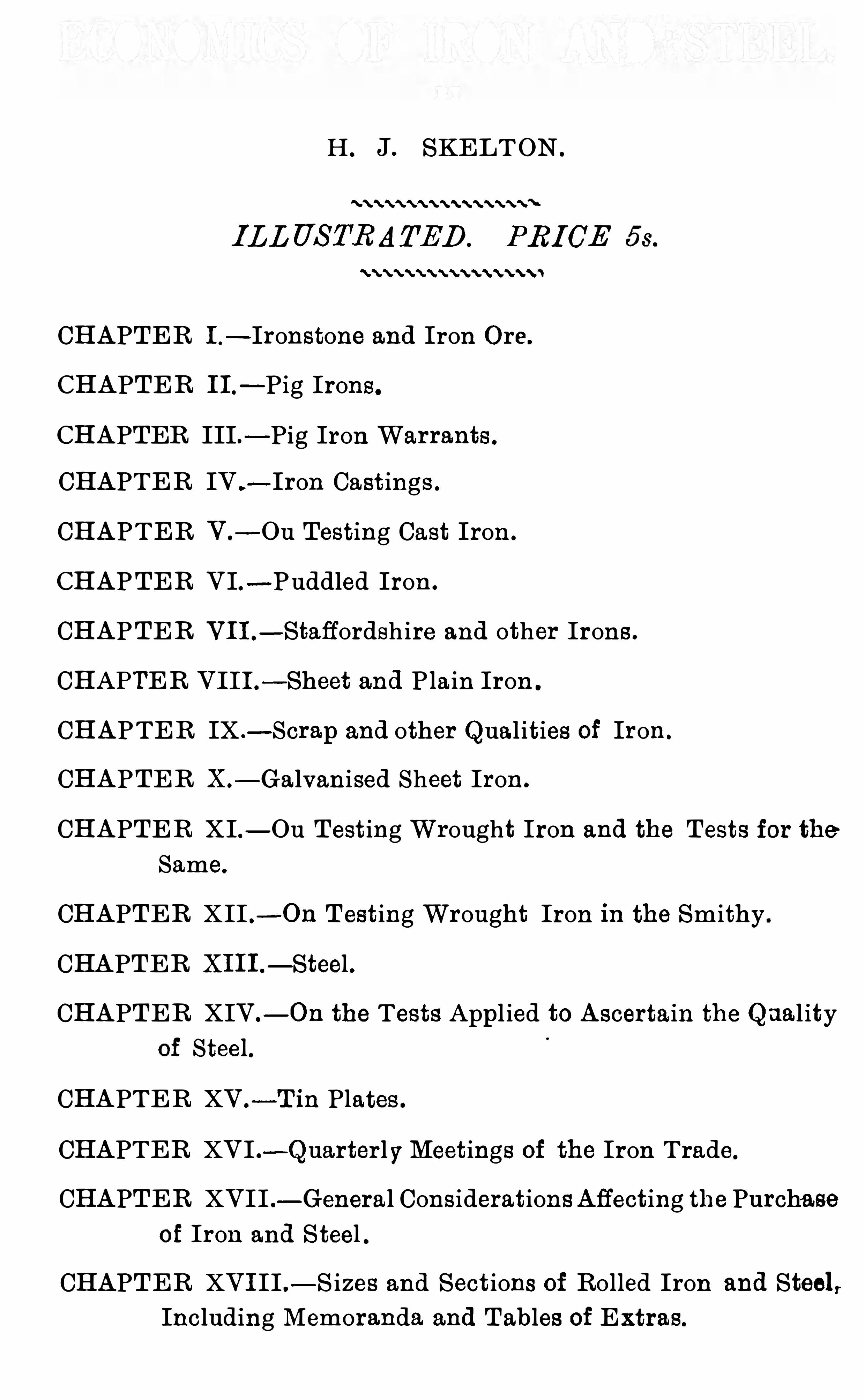
H . J. SKELTON .
I LLUSTRATED . PRI CE
CHAPTER I .
— Iron stone and Iron Ore.
CHAPTER 1 1 .— P ig Iron s .
CHAPTER III. -Pig Iron Warran ts .
CHAPTER IV .—Iron Cast ings .
CHAPTER V .-Ou Tes t ing Cast Iron .
CHAPTER VI. - Puddled Iron .
CHAPTER V I I .—Staffordshire and other Iron s .
CHAPTER VI I I .—Sheet and P la in Iron .
CHAPTER IX .—Scrap and other Qual it ies of Iron .
CHAPTER X .— Ga lvan ised Sheet Iron .
CHAPTER XI.— Ou Test ing Wrought Iron and th e Test s for th eSame.
CHAPTER XII . -On Test ing Wrought Iron in th e Sm ithy .
CHAPTER XML— Steel .
CHAPTER XIV.— On th e Test s Appl ied to Ascertain th e Qual ity
of Steel .
CHAPTER XV .-Tin Plates .
CHAPTER XVI . —Quarter lyMeet ings of th e Iron Trade.
CHAPTER XVII .— Genera l Cons iderat ion s Affect ing th e Purchase
Of Iron and Steel .
CHAPTER XVI II .— S izes and Sect ions of Rolled Iron and Steel ,Including Memoranda and Tables of Ext ras .

First Principles of MechanicalI
q lqeermg,
JOHN IMRAY, WITH ADDITIONS BY C . H . W . BIGGS .
I L L U S T R A T E D P R I C E 3 5 6 6 .
An at tempt i s made in th is book to exp lain th e pr in cip les OfMechan ica l En gineer ing in s imp le language , and without th eaid of abstruse mathemat ics . Th e calculat ion s are genera llyar ithmet ica l , and such as come wel l within th e comprehens ionOf th e beginner .
CHAPTER I .— Mechan ics of An t iquity . Modern Mach inery
Mechan ics and Chem is try. S tat ica l and Dynam ica lMachin es . S trength of Mater ials . Nomenclature. Un itof Work . Source of Energy . Appl icat ion of Energy.
Fr ict ion . Govern ing . Nature of Machines . Mechan ica lEducat ion .
CHAPTER 11 .— Mechan ica l Drawing . U se of Drawing . P lane
Surfaces . Draw ing Cubes . Drawing Cyl inders . Pro
ject ion . Sect ions . Perspect ive, etc . In strumen t s . Scaleof Drawings .
CHAPTER I I I .— S trength of Mater ials . S tra in s and Stresses .
Ten sion . Compress ion . Tran sverse Stress . Deflect ionand D isposa l of Mater ials . Ca lculat ions . Tors ion .
Shaft s . C lipping and Shear ing S tress .
CHAPTER IV .— Sources of Mechan ica l Power . Muscular Force.
W ind . Win dm ills . Water . Waterwheels . Turbines .
Weight . Fa l l ing Bod ies . Spr ings .
CHAPTER V .-Heat . Expans ive Power of Heat . E last ic ity
of Gases . Temperature and P res sure. Conden sat ion .
Expan s ion . S team Boi lers . S team Engines .
CHAPTER VI.— E lectr icity. Chem ica l Act ion .
CHAPTER VII .— Tran sm iss ion of Power . Rotary Mot ion .
Coup l ings . Clutches . P lummer B locks . Pulleys or
Drums . Toothed Wheels . Rec iprocat ing Mot ion . D is
con t inuous Mot ion . Rat chet . Cam . Mangle Mot ion .
Revers ing Gear . Dynamometer . Brakes etc.
CHAPTER VIII .— Tran smiss ion of Power. Water . CompressedA ir . E lectr ic ity .

Th eory and P ract ice of E lect ro
Depos i t ion , including every known mode Of
depos it ing meta ls , prepar ing metals for immersion , takingmoulds and render ing them conduct ing . By Dr . G Gore.
F.R.S. Il lustrated . Crown 8vo. Pr ice I s . 66 .
This lit t le work i s toowel l known to need a lengthy descr ipt ion .
I t h as long been acknowledged to be th e s implest elementarymanua l on th e subject , and Dr . Gore’
s abil it y and great careto put h is matter clear ly, is nowhere bet ter shown than in
th is lit t le book.
EDITED BY C . H . W . BIGGS .
Th e E lect r ical En gin eer .— A journal Of
E lect rica l Engineer ing . Publ ished every Fr iday. Pr ice 3d .
Contain s more, and ear lier informat ion about pract ica l workthan any other s im i lar techn ical paper .
EDITED BY C . H . W . BIGGS .
The Con t ract Jou rn a l .— Published every
Wednesday , Pr ice 6d .,h as devoted i t s at ten t ion dur ing i ts
“
fourteen years Of ex isten ce to th e discussion Of all quest ionsrelat ing
/
to cont ract s . I t h as full repor ts of all mat ters con
cern ing mun ic ipal con tract s , and h as ga ined a pos it ion un iquewith regard to techn ica l journals
,and i s without doubt
cons idered th e author it y in th e great subject Of contracts andtenders .
SHORTLY.
F ir s t Pr incip les of Bu i ld ing. By A.
Black , C.E. I llustrated.

THE MARINE ENG INEERS
ELECTR ICAL POCKET BOOK .
B y M . Suther land (E lectr ical Eng ineer at W . Denny Bros .
Shipbui ld ing Yard , Dumbarton .)
Th e Marine Engineers E lectrical Pocket Book .
PREFACE .
Th e wr iter h as frequent ly been asked by mar ine engineers ,
t o recommend a book which would g ive them a suffic ient in sight
into elect r ica l engineer ing to enable them to understand sh ip
installat ions without going too deep ly in t o elect r ical matters
i n genera l , and though there are many excellent books on
pract ical elect r ical engineer ing,h e h as not been ab le to find
one wh ich exact ly fulfils these condit ion s . H is Object therefore,
h as been to produce a compact and handy volume,wh ich
shou ld g ive an ins ight int o magnet ism and electr icity , with
descr ipt ions of th e var ious systems Of wir ing , generat ing p lant ,
fit t ings , measur ing instruments etc. ,used on board sh ip ,
avoiding as much as poss ible,all mat ter not d irect ly appl icable
to work of this nature .

The Dynamo.—By C. C.
Wa llis , WithTh eManagement ofAccumulators .
— By Sir D . Salomons .
Pr ice 5 8 . (Form ing th e firs t par t of th e Seventh revised anden larged Edit ion of th e same Author ’
s work , en t it led ‘E lectr icL ight In stallat ion s and th e Management of
Lightning Conductors and Lightning Guards — By
Ol iver J . Lodge,LL .D D. Sc .
,F .R .S In one
volume, with numerous I llust rat ion s . C rown 8vo. Pr ic'
é 1 5 s.
E lectric-Light Cab les , and th e Distr ibution of Elec
tricity .— By Stuart A. Russell,
With 107 I llustrat ion s . Pr ice
Alternating Currents of Electricity .—By Thomas H .
B lakes ley,M .A. ,
M. In st . C.E . Hon . Sec . Of th e Phys icalSoc iety. Third Ed it ion
,en larged . Pr ice 5 8 .
E lectric Transmission Of Energy , and its Transformation , Subdivision , and Distr ibution — By Gisbert
Kapp,
A pract ica l handbook , w ithnumerous I l lustrat ion s . Third Edit ion , thorough ly rev isedand en larged . Crown 8 vo. Pr ice 7s .6d .
Th e Telephone.— By W. H . Preece, F .R.S ,
and Ju lius
Ma ier,Ph .D . With 290 Illust rat ion s , Appendix , Tables , and
full Index . Pr ice 123 . 6d .
Maycock’
s First Book of E lectricity and Magnetism .
84 I llust rat ion s . Pr ice 23 . 6d .
E lectricity in our Homes and Work shops .— By Sydney
F.Wa lker , M. I .E .E A Pract ical Treat ise on
Auxi l iary E lectr ica l Apparatus . W ith numerous Illustrat ion s . Second Edit ion . Pr ice 5 5 .
E lectrical Instrument -makers for M ateurs.— By S
R. Bott one. A Pract ica l Handbook. With 7 1 Illustrat ion s .
Fifth Edit ion , r Pr ice 33 .