Zucchini Green T.HE transformers - SpecifiedBy
24
GREEN T.HE high efficiency transformers
-
Upload
khangminh22 -
Category
Documents
-
view
5 -
download
0
Transcript of Zucchini Green T.HE transformers - SpecifiedBy

GREEN T.HEhigh efficiencytransformers
cover+features.indd 1 04/08/2014 15:53

Global strengthbuilt on local knowledgeLegrand is the global specialist in electrical and digital building
infrastructures. Innovation is the driving force behind its
development. With an increasing investment in research and
development (circa 5% of sales) and more than 4,000 active
patents, the Legrand Group is focused on maintaining a high
rate of new product launches that present innovative solutions
to the market.
WIDE REACHING POWER DISTRIBUTION SOLUTIONSFrom Zucchini transformers through high
power distribution and rising main busbars
to Electrak’s powertrack, desk modules and
lighting control, Legrand’s power distribution
business unit provides market leading
solutions to the increasing demands of today’s
buildings.
Find out more at:
www.legrand.co.uk/power-distribution
WIDE REACHING POWER DISTRIBUTION SOLUTIONSWIDE REACHING POWER DISTRIBUTION SOLUTIONS
cover+features.indd 2 07/08/2014 09:47

WWW.LEGRAND.CO.UK/ZUCCHINI
GREEN T.HE TRANSFORMERS PRODUCT GUIDE
INTRODUCTIONMeeting the standard 2
Beneits to both users and the environment 4
PRODUCT SELECTIONSelection chart 12 kV class 6
Installation accessories 8
Enclosures 9
TECHNICAL SPECIFICATIONSInstalling a Zucchini cast resin transformer 10
Medium voltage winding 11
Low voltage winding 12
Protection against temperature rise 13
Protection against overloads 14
Protection against overloads by means
of measuring temperature 15
Environmental and climatic features /
ire resistance 16
CLE range 17
Main vector groups of transformers 18
Standard drilling details / special extended
LV bar arrangements 19
Compatibility with Zucchini SCP busbar 20
CONTENTS
1
cover+features.indd 1 07/08/2014 09:47

MEETING THE STANDARD
The EN 50541-1 Standard requires that distribution
transformers are built with the objective of ensuring high
energy effi ciency, while reducing the impact on the environment.
Legrand is committed to contributing to sustainable technological
development and fulfi ls the requirements of the EN 50541-1 standard
by introducing, within its Zucchini cast resin transformer range, the new
GREEN TRANSFORMER HIGH EFFICIENCY (Green T.HE).
These transformers ensure a consistent reduction in energy
consumption, resulting in fi nancial savings, and a decrease of
CO2 emissions released into the atmosphere.
The EN 50541-1 Standard
applies to 50 Hz, 100 kVA to 3150 kVA three-phase dry-type distribution transformers with maximum voltage per component not exceeding 36 kV.It replaces the following Standards: HD 538.1 S1:1992 + A1:1995 and HD 538.2 S1:1995 which were superseded on 02-01-2014.
2
cover+features.indd 2 07/08/2014 09:48

WWW.LEGRAND.CO.UK/ZUCCHINI
GREEN T.HE TRANSFORMERS PRODUCT GUIDE
CERTIFICATIONS AND
ACCEPTANCE TESTSPrior to being supplied to the
customer, Zucchini cast resin
transformers are individually
inspected and must pass the
acceptance and, when necessary,
type tests, if they are required at the
time of order.
At the end of the acceptance tests
a specific inspection certificate is
delivered with each transformer.
ACCEPTENCE TESTS
Measurement of winding resistance IEC 60076-1
Measurement of transformation ratio and check of polarity and connections IEC 60076-1
Measurement of short-circuit voltage and losses due to load IEC 60076-1
Measurement of no-load losses and no-load current IEC 60076-1
Insulation test with applied voltage IEC 60076-3
Insulation test with induced voltage IEC 60076-3
Measurement of partial discharges IEC 60076-11
TYPE TESTS (on request)
Atmospheric impulse test IEC 60076-3
Temperature rise test IEC 60076-2
SPECIAL TESTS (on request)
Measurement of sound level IEC 60076-10
Short-circuit withstand test IEC 60076-11
CLASSIFICATION
The classification of a cast resin transformer depends on the value of the no-load losses (P0), as well as the load losses (Pk), characteristics of the machine. More precisely, P0 losses are independent from the load, and remain constant for the whole period the transformer is connected to the electric power network. On the other hand, Pk losses only occur when the transformer is connected to a load, and are proportional to the square of the load itself.
STANDARDS
The EN 50541-1 Standard provides newloss level classifications for transformers; 3 of these apply to no-load losses, and 2 to load losses. The letter A identifies the most virtuous and economic level for both types of losses.
NO-LOAD
LOSSES (PO)LOAD
LOSSES (PK)
A0
B0
C0
Ak
BK
3
cover+features.indd 3 04/08/2014 15:56

LESS ISMORE
Reducing energy consumption not only reduces the impact on the environment it also has a signifi cant impact on operating costs, providing ongoing benefi ts thoughout the life of the building
4
Purchase price
Operating cost (20 years)
TOTAL COST
Class Ntransformer
£11,200
£40,777
£51,977
Class AAGreen T.HE
£14,800
£30,338
£45,138
FINANCIAL
SAVING
£6,839
SAVING IN TERMS OF
CO2 EMISSIONS
112 Tonnes CO2
In this example, the extra £3,600 required to purchase the Green T.HE transformer is recovered in less than six years, while the total saving for the 20 year period will be approximately £6,800
EUROPE
Rated power (SR): 1000 kVA
Primary no-load voltage (V10): 20 kV
Secondary no-load voltage (V20): 400 V
Uk: 6%
Transformer lifetime: 20 years
EXAMPLE OF POTENTIAL SAVINGS OBTAINED USING A GREEN T.HE TRANSFORMER
Note: Financial savings have been calculated taking into account the electric power supply costs listed on the EUROSTAT website.
EU-27: Cost of energy 0.0936 £/kWh. Equivalence 0,5778 kgCO2/kWh.GBP/EUR = 1.25 as at 30/06/2014.
cover+features.indd 4 04/08/2014 15:56

WWW.LEGRAND.CO.UK/ZUCCHINI
GREEN T.HE TRANSFORMERS PRODUCT GUIDE
WWW.LEGRAND.CO.UK/ZUCCHINI
GREEN T.HE TRANSFORMERS PRODUCT GUIDE
LIFETIME COSTS...
UNDERSTANDING THE BIGGER PICTUREThe purchase price of the transformer is only a marginal part of the Total Lifetime Cost (TLC) of the machine, while the operating cost (mainly connected with losses), represents over 80% of the total cost. This means that in a relatively short time it will be possible to recover the extra cost invested for the purchase of a Green T.HE transformer, compared with the cost of a standard loss transformer.
The example below compares the no-load losses (Po) and the load losses (Pk) of a Class N transformer as per standards: HD 538.1 S1:1992 + A1:1995 and HD 538.2 S1:1995 (which were superseded 02-01-2014), with transformers as per the EN 50541-1 Standard.
5
Typical 11kV-433Vtransformer
630kVA
800kVA
1000kVA
1250kVA
1600kVA
2000kVA
2500kVA
Po (W)
1450
1750
2000
2300
2800
3300
4300
Po (W)
1050
1350
1550
1900
2200
2800
3300
Po (W)
1150
1300
1500
1800
2200
2600
3200
Po (W)
1000
1100
1300
1500
1800
2200
2600
Po (W)
1000
1100
1300
1500
1800
2200
2600
Pk (W)at 120ºc
7600
9400
10000
12700
14000
18000
21000
N BoBk BoAk AoBk AoAk
Pk (W)at 120ºc
7600
9400
10000
12700
14000
18000
21000
Pk (W)at 120ºc
7100
8000
9000
11000
13000
16000
19000
Pk (W)at 120ºc
7300
9000
10000
12000
14500
18000
21000
Pk (W)at 120ºc
7100
8000
9000
11000
13000
15500
18500
Note: The time required to reach the break even point changes
depending on energy costs, and therefore the country in which the
analysis is carried out. This chart takes in to account Europe, and
an energy cost of 0.0936 £/kWh
TLC (Total Lifetime Cost) = PURCHASE COST + OPERATING COST
of the transformer
Once the transformer has exhausted its own operating cycle, all of the accompanying materials can be easily recycled or disposed of, as indicated in the PEP (Product Environmental Profile) document, which describes the environmental impact of a product during its lifecycle (from the extraction of the raw materials needed for its construction, through to its disposal). Available on request.
0 3 6 10 15 20
48,000
40,000
32,000
24,000
16,000
8,000
TLC
YEARS
BEP.Break Event Point
cover+features.indd 5 04/08/2014 15:56

6
Green T.HE MV/LV cast resin transformers12 kv insulation class
SR [kVA] Series Uk
[%]
Primary
voltage
[kV]
Secondary
voltage [V]
Insulation class
1·1 kV
Po
[W]
Pk
[W] at
120°C
Io
[%]
LwA-
Acoustic
power
[dB (A)]
Length
(A)
[mm]
Width
(B)
[mm]
Height
(C)
[mm]
Ic - wheel
centre
line
[mm]
R - wheel
diameter
[mm]
Weight
[kg]
BOX
type
100
AoAk 6 11 400 / 417 / 433 260 1 800 2·0 51 1 300 600 1 300 520 125 800 1
AoBk 6 11 400 / 417 / 433 260 2 000 2·0 51 1 300 600 1 300 520 125 800 1
BoAk 6 11 400 / 417 / 433 330 1 800 2·0 51 1 300 600 1 300 520 125 800 1
BoBk 6 11 400 / 417 / 433 320 2 000 1·8 51 1 000 600 1 100 520 125 570 1
160
AoAk 6 11 400 / 417 / 433 350 2 600 1·7 54 1 300 640 1 400 520 125 870 2
AoBk 6 11 400 / 417 / 433 350 2 700 1·7 54 1 300 640 1 400 520 125 870 2
BoAk 6 11 400 / 417 / 433 450 2 600 1·7 54 1 300 640 1 400 520 125 870 2
BoBk 6 11 400 / 417 / 433 440 2 700 1·7 54 1 050 600 1 140 520 125 800 1
200
AoAk 6 11 400 / 417 / 433 425 3 000 1·5 56 1 350 640 1 450 520 125 980 2
AoBk 6 11 400 / 417 / 433 425 3 100 1·5 56 1 350 640 1 450 520 125 920 2
BoAk 6 11 400 / 417 / 433 530 3 000 1·5 56 1 350 640 1 450 520 125 920 2
BoBk 6 11 400 / 417 / 433 540 3 150 1·5 56 1 150 620 1 190 520 125 900 1
250
AoAk 6 11 400 / 417 / 433 500 3 400 1·3 57 1 400 640 1 500 520 125 1 140 3
AoBk 6 11 400 / 417 / 433 500 3 500 1·3 57 1 400 640 1 500 520 125 1 090 3
BoAk 6 11 400 / 417 / 433 610 3 400 1·3 57 1 400 640 1 500 520 125 1 090 3
BoBk 6 11 400 / 417 / 433 580 3 700 1·3 57 1 250 630 1 220 520 125 1 000 2
315
AoAk 6 11 400 / 417 / 433 600 3 950 1·2 59 1 450 750 1 550 670 125 1 230 3
AoBk 6 11 400 / 417 / 433 600 4 050 1·2 59 1 450 750 1 550 670 125 1 180 3
BoAk 6 11 400 / 417 / 433 740 3 950 1·2 59 1 450 750 1 550 670 125 1 180 3
BoBk 6 11 400 / 417 / 433 700 4 600 1·0 59 1 250 750 1 250 670 125 1 200 2
400
AoAk 6 11 400 / 417 / 433 700 4 500 1·1 60 1 500 750 1 600 670 125 870 4
AoBk 6 11 400 / 417 / 433 700 4 900 1·1 60 1 500 750 1 600 670 125 870 4
BoAk 6 11 400 / 417 / 433 880 4 500 1·1 60 1 500 750 1 600 670 125 870 4
BoBk 6 11 400 / 417 / 433 790 5 400 1·6 60 1 050 600 1 140 520 125 1 350 3
500
AoAk 6 11 400 / 417 / 433 850 5 800 1·1 61 1 650 750 1 750 670 125 1 730 4
AoBk 6 11 400 / 417 / 433 850 5 900 1·1 61 1 600 750 1 700 670 125 1 630 4
BoAk 6 11 400 / 417 / 433 795 5 800 1·1 61 1 600 750 1 700 670 125 1 630 4
BoBk 6 11 400 / 417 / 433 920 6 700 0·8 61 1 300 750 1 500 670 125 1 500 3
630
AoAk 6 11 400 / 417 / 433 1 000 7 100 1·0 62 1 650 850 1 750 670 160 1 980 5
AoBk 6 11 400 / 417 / 433 1 000 7 300 1·0 62 1 600 850 1 750 670 160 1 890 5
BoAk 6 11 400 / 417 / 433 1 150 7 100 1·0 62 1 600 850 1 750 670 160 1 890 5
BoBk 6 11 400 / 417 / 433 1 050 7 600 0·7 62 1 500 850 1 590 670 160 1 800 4
800
AoAk 6 11 400 / 417 / 433 1 100 8 000 0·9 64 1 700 850 1 950 670 160 2 480 5
AoBk 6 11 400 / 417 / 433 1 100 9 000 0·9 64 1 650 850 1 900 670 160 2 330 5
BoAk 6 11 400 / 417 / 433 1 300 8 000 0·9 64 1 650 850 1 900 670 160 2 330 5
BoBk 6 11 400 / 417 / 433 1 350 9 400 0·7 64 1 500 850 1 740 670 160 2 100 4
Compliance with standard : IEC 60076-11 / EN 50541-1Frequency (Hz) : 50Adjustment, MT side : ± 2 x 2·5%Vectorial group : Dyn11 Thermal class of the insulating system : 155 °C (F) / 155 °C (F)Temperature rise : 100/100 K Class of use : E2-C2-F1 Certified CESI A9032391 IEC 60076-11Tolerances : according to IEC/CEIBIL : 75 kV
Technical information p. 10-20
Transformer_guide_CS4v6.indd 6 28/07/2014 13:54

7
SR [kVA] Series Uk
[%]
Primary
voltage
[kV]
Secondary
voltage [V]
Insulation class
1·1 kV
Po
[W]
Pk
[W] at
120°C
Io
[%]
LwA-
Acoustic
power
[dB (A)]
Length
(A)
[mm]
Width
(B)
[mm]
Height
(C)
[mm]
Ic - wheel
centre
line
[mm]
R - wheel
diameter
[mm]
Weight
[kg]
BOX
type
1 000
AoAk 6 11 400 / 417 / 433 1 300 9 000 0·8 65 1 650 1 000 2 100 820 160 2 670 6
AoBk 6 11 400 / 417 / 433 1 300 10 000 0·8 65 1 650 1 000 2 100 820 160 2 670 6
BoAk 6 11 400 / 417 / 433 1 500 9 000 0·8 65 1 650 1 000 2 050 820 160 2 670 6
BoBk 6 11 400 / 417 / 433 1 550 10 000 0·6 65 1 550 1 000 1 820 820 160 2 500 5
1 250
AoAk 6 11 400 / 417 / 4330 1 500 11 000 0·7 67 1 850 1 000 2 200 820 160 3 370 6
AoBk 6 11 400 / 417 / 433 1 500 12 000 0·7 67 1 850 1 000 2 150 820 160 3 130 6
BoAk 6 11 400 / 417 / 433 1 800 11 000 0·7 67 1 850 1 000 2 150 820 160 3 320 6
BoBk 6 11 400 / 417 / 433 1 900 12 700 0·5 67 1 550 1000 2 000 820 160 2 950 5
1 600
AoAk 6 11 400 / 417 / 433 1 800 13 000 0·6 68 1 950 1 000 2 200 820 160 3 900 6
AoBk 6 11 400 / 417 / 433 1 800 14 500 0·6 68 1 950 1 000 2 150 820 160 3 760 6
BoAk 6 11 400 / 417 / 433 2 200 13 000 0·6 68 1 950 1 000 2 150 820 160 3 760 6
BoBk 6 11 400 / 417 / 433 2 200 14 000 0·4 68 1 650 1 000 2 180 820 160 3 550 6
2 000
AoAk 6 11 400 / 417 / 433 2 200 15 500 0·5 70 2 000 1 310 2 400 1070 200 4 560 7
AoBk 6 11 400 / 417 / 433 2 200 18 000 0·5 70 2 000 1 310 2 250 1 070 200 4 420 7
BoAk 6 11 400 / 417 / 433 2 600 16 000 0·5 70 2 000 1 310 2 250 1 070 200 4 420 7
BoBk 6 11 400 / 417 / 433 2 800 18 000 0·4 70 1 800 1 310 2 260 1 070 200 4 300 6
2 500
AoAk 6 11 400 / 417 / 433 2 600 18 500 0·4 71 2 150 1 310 2 450 1 070 200 5 470 7
AoBk 6 11 400 / 417 / 433 2 600 21 000 0·4 71 2 100 1 310 2 350 1 070 200 5 370 7
BoAk 6 11 400 / 417 / 433 3 200 19 000 0·4 71 2 100 1 310 2 350 1 070 200 5 420 7
BoBk 6 11 400 / 417 / 433 3 300 21 000 0·3 71 2 050 1 310 2 390 1 070 200 5 250 7
3 150
AoAk 6 11 400 / 417 / 433 3 150 22 000 0·4 74 2 250 1 400 2 550 1 070 200 6 010 8
AoBk 6 11 400 / 417 / 433 3 150 26 000 0·4 74 2 200 1 400 2 550 1 070 200 5 800 8
BoAk 6 11 400 / 417 / 433 3 800 22 000 0·4 74 2 250 1 400 2 550 1 070 200 6 050 8
BoBk 7 11 400 / 417 / 433 3 950 26 000 0·3 74 2 150 1 310 2 400 1 070 200 6 250 7
A
ØR=Ic Ic=
C
=
5040 (Ø125)
70 (Ø200)(Ø160)
=
B
60
MM
12
Values are for reference only. Construction drawings must be used for design Data provided may be modified without warning for reasons of technical production or product improvement
Other insulation classes, such as 17·5, 24 and 36 kV, available on request along with other primary voltages, such as 6·6 kV, please contact us on +44 (0) 845 600 6266
n Technical dimensions
Transformer_guide_CS4v6.indd 7 28/07/2014 13:54

8
Green T.HE MV/LV cast resin transformersinstallation accessories
For details of corresponding connection interfaces for the SCP busbar range see p. 19
Temperature control devices
Central units are supplied unassembledType Description
1 220035 VRT200 Fan control1 220002 T154 Temperature control for 4 Pt100 probes1 220023 MT200L Temperature control for 4 Pt100 probes1 220010 T119 DIN Temperature control for 6 PTC probes,
preset for DIN rail mounting1 220004 T119 Temperature control for 6 PTC probes
Non-magnetic thermometer
Both thermometer and support bracket must be ordered
1 250662 Thermometer (supplied without supporting bracket)1 250005 Thermometer support bracket (must be ordered
alongside thermometer)
Pack Cat. Nos. Surge arrester kit
Supplied mounted on the transformer
Fitting of surge arresters increases warranty to 24 months
VoltageVn (kV)
1 130054D 11
1 130055D 15
1 130056D 20
Pack Cat. Nos. Temperature measurement sensorsTemperature measurement sensors are supplied mounted on to the transformer and wired to aluminium IP 65 junction box
TypeRange (kVA) No. ∆t (°C) Installation
3 200073 Pt100 ≤2 000 3 – on the LV (3) windings
3 200074 Pt100 >2 500 3 – on the LV (3) windings
4 200137 Pt100 ≤2 000 3 + 1 – on the LV (3) windings + on the core (1)
4 200138 Pt100 >2 500 3 + 1 – on the LV (3) windings + on the core (1)
6 CB00120 PTC – 3 x 2 130-140 on the LV (3 pairs) windings for alarm and release
6 CB02400 PTC – 3 x 2 110-120 on the LV (3 pairs) windings for alarm and release
Selection charts p. 6-7Technical information and dimensions p. 10-20
Rubber supports (anti vibration)
4 anti-vibration pads for mounting under transformer casters
RangekVA
1 170019 100-1 600
1 170020 2 000-3 150
IP 65 junction box Pt100 temperature measurement sensor
Transformer_guide_CS4v6.indd 8 28/07/2014 13:54

9
Green T.HE MV/LV cast resin transformersinstallation accessories (continued) and enclosures
Pack Cat. Nos. Ventilation bars
Ventilation bars allow a temporary increase of the rated power (at rated operation conditions) :
1. When ordering an AN/AF transformer, the ventilation bars will be supplied fitted to the transformer
2. When ordering a transformer, and the AN to AN/AF conversion (within the limits indicated in the table below) is completed after delivery, the purchaser will have to return the original data plate to the manufacturer, who shall then supply a new data plate and the corresponding assembly instructions
Range (kVA) ∆Power (%) Notes1 CB02443 100-250 +30
A temporary increase in rated conditions
1 CB02453 315-800 +301 CB02463 1 000-1 250 +301 CB01413 1 600-2 500 +301 CB01411 3 150 +301 CB02444 100-250 +401 CB02454 315-800 +401 CB02464 1 000-1 250 +401 CB01414 1 600-2 500 +401 CB01412 3 150 +40
Ventilation bars
Pack Cat. Nos. Enclosures
Insulation Class 12 / 17·5 / 24 kVDegree of protection : IP 21 / IP 23 / IP 31Colour RAL 7035Boxes can be supplied or assembled on the transformer For a pre-assembled box add the ‘M’ suffix to the Cat. No. (e.g. Cat. No. 231043M)
Box type
IP degree
Dimensions (mm)Weight
(kg)Length (A) Width (B) Height (C)
1 230316 1 IP21 1 600 900 1 470 1201 230288 1 IP31 1 600 900 1 470 1301 230353 1 IP23 1 600 900 1 470 1201 230211 2 IP21 1 700 950 1 580 1401 230273 2 IP31 1 700 950 1 580 1401 230263 2 IP23 1 700 950 1 580 1401 230212 3 IP21 1 800 1 000 1 680 1601 230215 3 IP31 1 800 1 000 1 680 1701 230234 3 IP23 1 800 1 000 1 680 1601 230204 4 IP21 1 900 1 050 1 950 1801 230277 4 IP31 1 900 1 050 1 950 2001 230222 4 IP23 1 900 1 050 1 950 1801 230213 5 IP21 2 050 1 100 2 200 2101 230221 5 IP31 2 050 1 100 2 200 2301 230223 5 IP23 2 050 1 100 2 200 2101 230214 6 IP21 2 300 1 310 2 500 2801 230267 6 IP31 2 300 1 310 2 500 3401 230249 6 IP23 2 300 1 310 2 500 2801 230287 7 IP21 2 500 1 310 2 700 3001 230309 7 IP31 2 500 1 310 2 700 3601 230371 7 IP23 2 500 1 310 2 700 3001 231042 8 IP21 2 700 1 400 2 800 3201 231043 8 IP31 2 700 1 400 2 800 3801 231044 8 IP23 2 700 1 400 2 800 320
Selection charts p. 6-7Technical information and dimensions p. 10-20
Transformer enclosure colour RAL 7035 AREL door lock on the enclosure, Cat. No. 230076
A
C
B
For 36 kV enclosures’ dimensions and weights, please contact us on +44 (0) 845 600 6266
n Technical dimensions
Transformer_guide_CS4v6.indd 9 28/07/2014 13:54

10
Green T.HE MV/LV cast resin transformersconstructional characteristics
n Installing a Zucchini cast resin transformer
Zucchini cast resin transformers are distinguished by their high quality productionUsing state-of-the-art constructional techniques and equipment, quality is assessed throughout the production process and via a rigorous checking process in the final phase, resulting in a high quality, reliable product
Zucchini cast resin transformers can be installed quickly and easilyWith no additional construction or building activities necessary, safe installation is ensured by following a few simple steps :
• Standard execution – indoor installation, in dry / clean environments, protected from direct sunlight, with no possibility of water ingress
• Altitude no higher than 1 000 m above sea level (for higher installations, contact us on +44 (0) 845 600 6266)
• Room temperature with transformer in operation (for higher values, contact us on +44 (0) 845 600 6266) : •T minimum – 25°C •T maximum + 40°C
• With a standard execution, transformers are designed in accordance with IEC Standard 60076-11 for the following room air temperatures : • 40°C at peak times • 30°C as a monthly average in the warmest month • 20°C as a yearly average
• To protect the transformers from external environment impacts and/or people from the risk of having direct contact, a set of standard enclosures is available with different degrees of protection : IP 21 / IP 31 / IP 23
1 MV windings in aluminium strip coils, cast in resin under vacuum
2 Core in three columns in magnetic lamination with high-permeability oriented crystals, also available with low losses
3 LV windings in aluminium plate/sheet and vacuum-cast impregnated insulation material
4 LV connections upwards (standard) or downwards version (on request)
5 MV connections upwards (standard) or downwards version (on request)
6 Rubber inserts attenuate the transmission of vibrations between core and windings, and reduce operating noise generated by the transformer to a minimum, as well as absorbing the thermal expansion of the components
7 Off load links on the MV side to adapt the primary voltage to the mains, which can be set with transformer switched OFF
8 Structure, armatures and carriage, manufactured from strong painted sheet steel
9 Carriage with bi-directional castors
10 The epoxy resin insulation makes the transformer low maintenance
11 The operating temperature is checked by Pt100 sensor or PTC in the LV windings
12 Lifting eyebolts conform to the DIN-580 UNI-2947 standards with safety hooking at 4 points
13 Optional pre-equipment for connection of the LV connection to Zucchini busbar trunking system
14 Class F insulating material, at 155°C, allowing for a temperature rise of 100°K. (100°C)
15 The carriage allows safe movement and is pre-equipped for mounting IP reinforced boxes
5
7
8
6
1
2
3
10 - 14
9 - 15
11 13 4 12
Transformer_guide_CS4v6.indd 10 28/07/2014 13:54

11
n Medium voltage (MV) winding
Green T.HE MV/LV cast resin transformerstechnical information
The medium voltage winding, made by highly automated winding machines, is constructed with the continuous disk technique and made in aluminium strip, interleaved with double insulationThis type of working produces uniformity of the internal and external thickness of the resin and guarantees uniform resistance to the dielectric stresses to which the transformer will be subjected in the inspection phase or during its operation at the place of installation
The primary winding has off load links to adjust the primary voltage equal to the value ± 2 x 2·5%, made with brass bushes protruding from the resin, and brass nuts and bolts with indelible numbering (not with adhesive labels)The thermal class of the insulating materials used corresponds to class F, with the temperature rises allowed by standard IEC 60076-11
Modern electronically controlled winding machines The pouring system under high vacuum
The technology used in making the MV windings in strips, rather than in wire, puts less stress on the insulation between the turnsIn traditional windings, made with a circular-section conductor, each layer of the winding is made up of a number of turns side by side. In windings made with strip conductors, each layer is made up of just one turnIf the voltage of a single turn of a winding is denoted by u
s, in strip windings the voltage between turns belonging to two adjacent layers is
always us, while in traditional windings this voltage assumes the maximum value of (2n – 1) u
s, as shown in the diagram below
Division of the voltage between the turns of the medium voltage winding
Winding made with wire conductors : the voltage increases with the number of turns
Winding made with strip conductors : the voltage is divided uniformly
1 2 3 4 5 6 7
2 3 4 5 6 7 8
U
1
2
3
4
5
6
7
8
➃
➄
➅
➆
➇
➃
➂
➁
➀
➅
➃
➄
➅
➂
➆
➂
➆
➁
➇
➁
➇
➀
U
Transformers with strip windings thus have a greater capacity of resistance to impulse voltages and at industrial frequencies, as well as a lower probability of occurence of localised partial discharges. Strip winding also has the advantage of drastically reducing the axial forces due to short-circuit currents
Transformer_guide_CS4v6.indd 11 28/07/2014 13:54

12
Green T.HE MV/LV cast resin transformerstechnical information (continued)
TIG welding in controlled atmosphere for LV connections
LV winding system
n Low voltage (LV) winding
The low voltage winding is made up of a single aluminium strip, of the same mechanical height as the MV electrical winding, with an interleaved sheet of insulating material which can be Class F or Class H. Making the winding in this way guarantees a compactness which forms a single cylinder that resists any axial and radial forces that may arise from a short-circuitAll the welds of the conductor strip with the output bars are made by butt welding in an inert atmosphere and under electronic control, so as to avoid any excess of material which could, by repeated stress, affect or damage the insulation interposed between output terminal and the following turnThis winding is then impregnated with epoxy resin, under vacuum, to confer the necessary compactness and homogeneity, as well as avoiding the absorption of humidity during the transformer’s lifetime, wherever it may operateThis treatment means the system meets classiication at level F1 according to standards IEC 60726 and IEC 60076-11
Transformer_guide_CS4v6.indd 12 28/07/2014 13:54

13
n Protection against temperature rise
During its normal operation a transformer has no-load losses and load losses which fundamentally translate into dispersed thermal energy. This energy depends on the construction of the transformer itself, its power and the installation conditions. It should be remembered that the energy dispersed thermally is proportional to the transformer temperature minus the room temperature. At a given room temperature, the transformer temperature depends mainly on the load losses. As the load increases consequently the losses and the room temperature increase favouring a more rapid degradation of the insulations and thus a greater probability of failure of the dielectric. This situation could also occur when, with equal losses due to load, the room temperature and consequently the transformer temperature, increase. The IEC 60085 standard deines insulation classes which indicate the maximum temperatures that can be reached by the transformers in their normal operation and which must not be exceeded
Temperature rises depend not only on the load and the overcurrents that may be detected by the protection devices, but also on environmental factors (ineficiency of the cooling system, fault on the forced ventilation and increase of the room temperature) which inluence the dispersal of heat produced by the transformer’s speciic losses. For this reason electronic temperature measuring devices are normally provided. These are necessary to trigger the alarm or transformer protection. The following temperature sensors are available for Zucchini transformers: Pt100 thermosensors and PTC thermistors :
• Pt100: supplies a signal proportional to the temperature measured• PTC: supplies an ON/OFF signal depending on whether the temperature measured is less or more than the sensor’s threshold
The sensors are positioned in the hot point of the windingBoth the Pt100 and PTC signals must be processed by the temperature control unit, which does not form part of the standard equipment
On request other accessories are available to check the temperature :• a separate temperature display, to be installed on the control panel• an output relay for alarm and release and control of the fans
Pt100 sensor to check the temperature
Insulation classes
Class TransformersAverage temperature rise
limits, at rated current
Class F (155°C) resin 100° K
Maximum transformer alarm and release temperature values
Transformer type Room (°C) Alarm (°C) Release (°C)
Resin 40 130 140
When combined with control sensors, the following can also be supplied, if required :
• T154 Unit or MT200 Unit : equipment used for controlling the Pt100 thermistors with temperature display, output relay for alarm, optional trip and control of the ventilation bars supplied as a detached part to be installed on the electric panel
• T119 Unit : equipment used for controlling the PTC thermistors with output relay for alarm, optional trip and control of the ventilation bars supplied for being installed on the electric panel
Ventilation accessories :
• Zucchini cast resin transformers can be equipped at the factory with special ventilation bars These special tangential fans are designed to allow temporary and limited increase of the power delivered by the transformer, up to + 40% of the rated power
• VRT200 Unit : equipment for automatic activation and control of the fans
Temperature rise limits for cast resin transformers
Part Insulating system temperature (°C) Maximum temperature rises (K)
Windings :temperature rise measured with the heating element variation method
155 (F) 100
Core, metal parts and adjacent materials
–
In no case must the temperature reach values which would damage the core itself, other parts or adjacent materials
Transformer_guide_CS4v6.indd 13 28/07/2014 13:54

14
Green T.HE MV/LV cast resin transformerstechnical information (continued)
Overload in public distribution In public distribution, in the short term priority is given to continuity of service. For this reason overloads do not generally lead to switching the transformer “OFF”. Again for the same reason generally low voltage circuits are always overdimensioned and consequently an overload of the transformer never corresponds to an overload of the conductors. However, attention should be paid when the overloads repeat too frequently. In this situation the distributing organisation should replace the transformer with a model with greater power
n Protection against overloads
Overload is the phenomenon which occurs when the value of current absorbed by the system is higher than the rated value. The persistence of an overload inevitably leads to exceeding the acceptable temperature rise limits speciied for the transformer, with the consequent risk of deterioration of the insulating materials. Exceptionally, in certain abnormal service conditions, it may be acceptable to exceed the overload and temperature rise thresholds, to the detriment of the transformer’s expected lifetime. This situation is sometimes preferable to an interruption of service (due to a temporary power peak) which could cause considerable material and economic damage. In most cases the overloads are transient and thus generally do not affect the thermal equilibrium. The ‘acceptable’ overload level is a function of the user’s need for service continuity and the type of system itself. For insulating-liquid transformers the circulation of the cooling oil and the shape of the radiator containment tanks allow the rapid restoration of the insulation and the reduction of partial discharges, as well as allowing the transformer to reach its operating temperature quickly
For cast resin transformers, the cooling component is air, and thus it takes longer to reach the operating temperature. In these conditions cast resin transformers may be more overloaded and thus may be used in systems with loads where there are frequent breakaway starting currents. This is true as long as the temperature rises on the windings do not remain above the allowable values for too long. A partial solution of the problem may be the use of radial fans afixed to the cast resin transformers, allowing a temporary transformer overload up to 150% of the rated power. It should, however, be remembered that as the power increases the losses due to load increase. As they depend on the square of the current they can reach up to 2·25 times the rated value. Radial fans should only be used in special and temporary cases to cool the windings or to have a sort of power reserve which may be used in emergency situations
I
5kA
10mA15kV 75kV U
10Ir
5Ir
2Ir
Ir
5s 20s 2mn 10mn 1h 5h t 10s 1mn 5mn 20mn 2h
Overload capacity of an oil transformer
Overload in industrial distributionIn an industrial installation, the overload can last for a short or long time. In these installations the main distribution board equipped with protective circuit breakers against overload and short-circuit is always immediately downstream of the transformers. Management of the overload is in fact delegated to the circuit breakers on the low voltage side which will detach the loads in an automatic or controlled way
Overload in service distributionIn service installations, such as ofices and shopping centres, continuity of service is fundamental. In these types of application conditions of regular load, which have starting regimes or similar behaviour, rarely occurTo guarantee maximum continuity of service, even when there are overloads, it is essential that the loads considered non-priority are managed and disconnected when needed by the transformer on the low voltage side
Transformer_guide_CS4v6.indd 14 28/07/2014 13:54

15
Fan control unit
Temperature control unit
As previously stated, overload is fundamentally associated to a temperature rise, which is the real component to be kept under control, because its effects could lead to the rapid deterioration of the insulation materials and to the failure of the transformer’s dielectric properties. Verifying the temperature is a determining factor in protection of the transformer itself. To check the temperature therefore, cast resin transformers are generally equipped with thermoresistors, in turn connected to electronic control units, which signal or directly release the transformer when the defi ned thresholds are exceeded. Zucchini cast resin transformers have these thermoresistors installed near the parts which are most critical from the thermal point of view
n Protection against overloads by means of measuring the temperature
Example of installation of a Pt100 temperature control unit
Transformer_guide_CS4v7.indd 15 07/08/2014 09:57

16
Green T.HE MV/LV cast resin transformerstechnical information (continued)
Thanks to the use of a high-quality epoxy resin, all Zucchini transformers reduce environmental impact to a minimum and conform to the following classes :
• environmental class E2
• climatic class C2
• ire behaviour class F1
The thermal class of the insulating materials used corresponds to class F and the temperature rises are those given in the speciic standards for the transformer product
ENVIRONMENTAL
TESTS
E0No condensation on the transformer, negligible pollution, installation in a clean and dry room
E1Occasional condensation and little pollution
E2The transformer is subject to consistent condensation, to intense pollution, or to both phenomena
CLIMATIC TESTS
C1The transformer will not operate at temperatures lower than -5°C, but may be exposed to -25°C during transport and storage
C2The transformer can operate and be transported and stored at temperatures down to -25°C
FIRE RESISTANCE
F0The risk of ire is not expected and no measures are taken to limit inlammability
F1The transformer is subject to the risk of ire and reduced inlammability is required. Fire on the transformer must be extinguished within laid-down limits
n Environmental and climatic features, and fire resistance
Standard IEC 60076-11 (2004) uses an alphanumeric code to identify the environmental, climatic and ire behaviour classes of dry-type transformers
• environmental class (E0 – E1 – E2)
• climatic class (C1 – C2)
• ire behaviour class (F0 – F1)
Transformer_guide_CS4v6.indd 16 28/07/2014 13:54

17
Example of an electromagnetic emission and noise measurement report
n CLE range (certified low electromagnetic emission)
CLE transformers (certified low electromagnetic emissions) are specifically designed and built for reducing electromagnetic emissions. This is the ideal solution for places continuously attended by people or, for example, with particularly sensitive electronic equipment As a result, the Zucchini cast resin CLE range is fully in compliance with the DPCM regulations of 8/7/2003 (electromagnetic emissions lower than 10 microTesla), and the Zucchini quality target is set to a threshold of 3 microTesla Legrand provides each CLE cast resin transformer with a specific measurement ratio of the electromagnetic emissions
Furthermore, by using a modern semi-anechoic chamber located inside the Legrand laboratory, the CLE transformation systems can also be supplied with a noise measurement ratio based on different emission bands
Transformer_guide_CS4v6.indd 17 28/07/2014 13:54
18
Ur
Ur 3
Ur, I3
Zig-Zag
Ir
Ir
Ur
Triangle
Ir
Ir 3
Ir 3
Ur
Ur 3
Star
Ir
D y
n
Type of connection
Possible accessible star centre
Primary windings (upper case letter)
Secondary windings (lower case letter)
Group
Angular phase shift in advance
11
Ur
Ur 3
Ur, I3
Zig-Zag
Ir
Ir
Ur
Triangle
Ir
Ir 3
Ir 3
Ur
Ur 3
Star
Ir
D y
n
Type of connection
Possible accessible star centre
Primary windings (upper case letter)
Secondary windings (lower case letter)
Group
Angular phase shift in advance
11
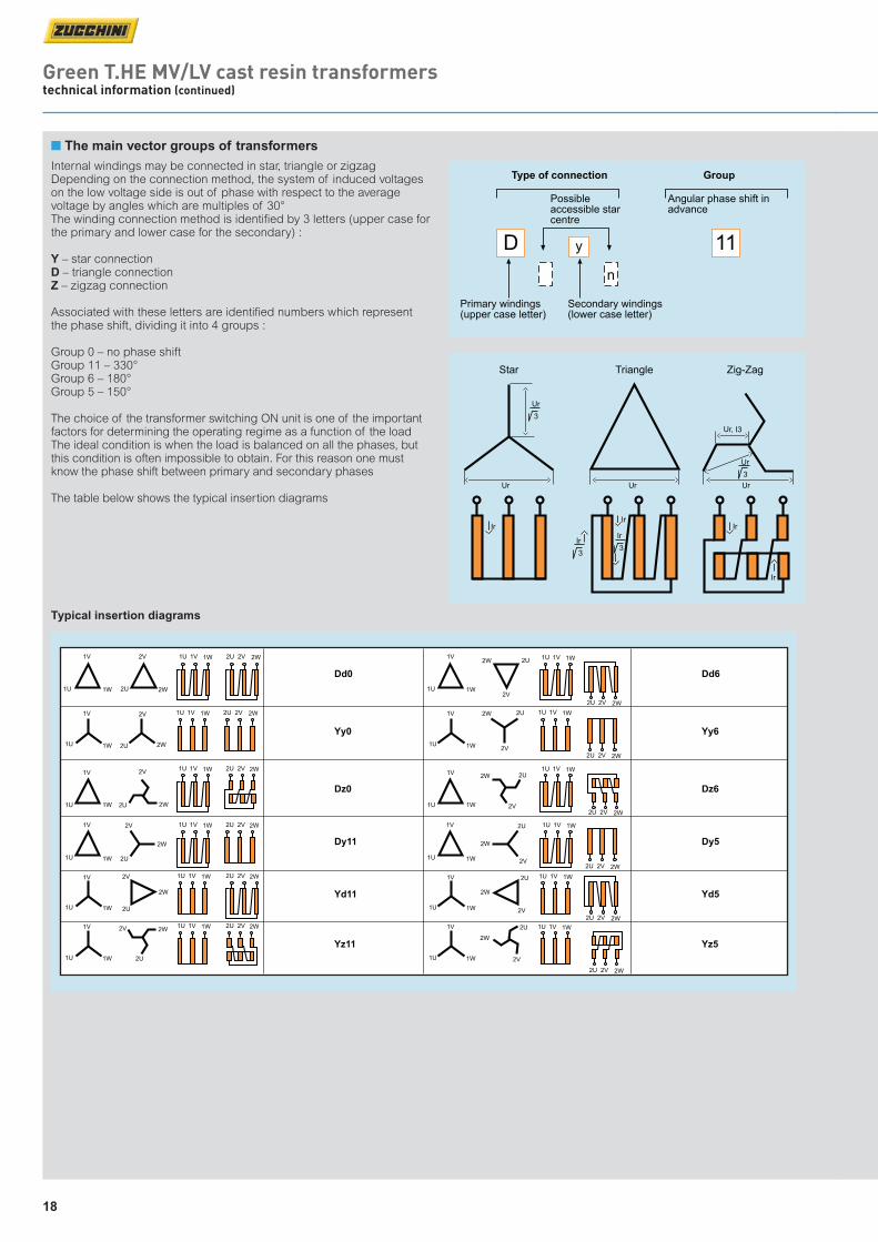
n The main vector groups of transformers
Internal windings may be connected in star, triangle or zigzag Depending on the connection method, the system of induced voltages on the low voltage side is out of phase with respect to the average voltage by angles which are multiples of 30°The winding connection method is identiied by 3 letters (upper case for the primary and lower case for the secondary) :
Y – star connectionD – triangle connectionZ – zigzag connection
Associated with these letters are identiied numbers which represent the phase shift, dividing it into 4 groups :
Group 0 – no phase shiftGroup 11 – 330°Group 6 – 180°Group 5 – 150°
The choice of the transformer switching ON unit is one of the important factors for determining the operating regime as a function of the load The ideal condition is when the load is balanced on all the phases, but this condition is often impossible to obtain. For this reason one must know the phase shift between primary and secondary phases
The table below shows the typical insertion diagrams
1W
1W
1W
1W
1W
1W
1U
1U
1U
1U 1U
1U
1U
1V
1V
1V
1V 1V
1V
1V
1W
1W
1W
1W
1W
1W
1U
1U
1U
1U
1U
1V
1V
1V
1V
1V
2W
2W
2W
2W
2W
2W
2W
2W
2W
2W
2W
2W
2U
2U
2U
2U
2U
2U
2U
2U
2U
2U
2U
2U
2V
2V
2V
2V
2V
2V
2V
2V
2V
2V
2V
2V
Dd01W1U 1V 1W1U 1V
1W1U 1V
1W1U 1V
1W1U 1V
1W1U 1V
1W1U 1V
2W2U 2V
2W2U 2V
2W2U 2V
2W2U 2V
2W2U 2V
2W2U 2V
2W2U 2V
1W1U 1V 2W2U 2V
1W1U 1V 2W2U 2V
1W1U 1V 2W2U 2V
1W1U 1V 2W2U 2V
1W1U 1V 2W2U 2V
Yy0
Dz0
Dy11
Yd11
Yz11
Dd6
Yy6
Dz6
Yz5
Yd5
Dy5
Typical insertion diagrams
Green T.HE MV/LV cast resin transformerstechnical information (continued)
Transformer_guide_CS4v6.indd 18 28/07/2014 13:54

19
n Special extended LV bar arrangements
40
40
D= =
4 x Ø13
20
80
32
32
C= =
2 x Ø13
14
60
50
50
E= =
4 x Ø15
25
100
50
25
B= =
Ø15
60
60
F= =
4xØ18
30
120
40
20
A= =
Ø13
n Standard drilling details
LV connection terminals are manufactured from aluminium Special CUPAL bimetallic plates can be supplied for the connection of copper cables
All the data given can be modified without warning for reasons of technical production or product improvement
The Legrand Group offer meets the needs of any installation Cast resin transformers have specifically designed connections for Zucchini busbars
The versions shown represent some of the standardised solutions
For the outgoing busbar run from the transformer
LV side
Type A setup
LV side
Type B setup
LV side
Type C setup
Cast resin transformer
A technical drawing of the transformer is needed when creating an ATR connection interface
Extended MV bars are available on request, contact us on +44 (0) 845 600 6266
n ATR connection interface
Range Thickness Width No. of Ø holes Drawing kVA [mm] [mm] holes [mm]
100 4 40 1 13 160 4 40 1 13
200 5 50 1 15 400 5 50 1 15
500 6 60 2 13 630 6 60 2 13 800 8 60 2 13
1 000 8 80 4 13
1 250 8 100 4 15
1 600 10 120 4 18 2 000 12 120 4 18 2 500 16 120 4 18 3 150 20 120 4 18
A
B
C
D
E
F
Transformer_guide_CS4v6.indd 19 28/07/2014 13:54

20
Green T.HE MV/LV cast resin transformerstechnical information (continued)
n Compatibility with Zucchini SCP busbar
Transformer Busbar (copper) Insulation 433 V kVA class current IK 6 % Connection (kVA) (kV) (A) (kA) Family component
630 841 14·10 SCP 1 000 A 65281011P
800 1 067 17·80 SCP 1 250 A 65281013P
1 000 1 334 22·30 SCP 1 600 A 65281015P
1 250 1 667 27·80 SCP 2 000 A 65281016P
1 600 2 134 35·60 SCP 2 500 A 65391018P
2 000 2 667 44·50 SCP 3 200 A 65391015P
2 500 3 334 55·60 SCP 4 000 A 65391016P
3 150 4 201 70·021 SCP 5 000 A 65391018P
12, 17·5,
24, 36
Transformer Busbar (copper) Insulation 417 V kVA class current IK 6 % Connection (kVA) (kV) (A) (kA) Family component
630 873 14·60 SCP 1 000 A 65281011P
800 1 108 18·50 SCP 1 250 A 65281013P
1 000 1 385 23·10 SCP 1 600 A 65281015P
1 250 1 731 28·90 SCP 2 000 A 65281016P
1 600 2 216 37·00 SCP 2 500 A 65391018P
2 000 2 770 46·20 SCP 3 200 A 65391015P
2 500 3 462 57·70 SCP 4 000 A 65391016P
3 150 4 362 72·701 SCP 5 000 A 65391018P
12, 17·5,
24, 36 Transformer Busbar (copper) Insulation 400 V kVA class current IK 6 % Connection (kVA) (kV) (A) (kA) Family component
630 910 15·20 SCP 1 000 A 65281011P
800 1 155 19·30 SCP 1 250 A 65281013P
1 000 1 444 24·10 SCP 1 600 A 65281015P
1 250 1 805 30·10 SCP 2 000 A 65281016P
1 600 2 310 38·50 SCP 2 500 A 65391018P
2 000 2 887 48·20 SCP 3 200 A 65391015P
2 500 3 609 60·20 SCP 4 000 A 65391016P
3 150 4 547 75·781 SCP 5 000 A 65391018P
12, 17·5,
24, 36
Transformer Busbar (aluminium) Insulation 400 V kVA class current IK 6 % Connection (kVA) (kV) (A) (kA) Family component
630 910 15·20 SCP 1 000 A 60281012P
800 1 155 19·30 SCP 1 250 A 60281014P
1 000 1 444 24·10 SCP 1 600 A 60281016P
1 250 1 805 30·10 SCP 2 000 A 60281017P
1 600 2 310 38·50 SCP 2 500 A 60391014P
2 000 2 887 48·20 SCP 3 200 A 60391016P
2 500 3 609 60·20 SCP 4 000 A 60391017P
12, 17·5,
24, 36
Transformer Busbar (aluminium) Insulation 433 V kVA class current IK 6 % Connection (kVA) (kV) (A) (kA) Family component
630 841 14·10 SCP 1 000 A 60281012P
800 1 067 17·80 SCP 1 250 A 60281014P
1 000 1 334 22·30 SCP 1 600 A 60281016P
1 250 1 667 27·80 SCP 2 000 A 60281017P
1 600 2 134 35·60 SCP 2 500 A 60391014P
2 000 2 667 44·50 SCP 3 200 A 60391016P
2 500 3 334 55·60 SCP 4 000 A 60391017P
12, 17·5,
24, 36
Transformer Busbar (aluminium) Insulation 417 V kVA class current IK 6 % Connection (kVA) (kV) (A) (kA) Family component
630 873 14·60 SCP 1 000 A 60281012P
800 1 108 18·50 SCP 1 250 A 60281014P
1 000 1 385 23·10 SCP 1 600 A 60281016P
1 250 1 731 28·90 SCP 2 000 A 60281017P
1 600 2 216 37·00 SCP 2 500 A 60391014P
2 000 2 770 46·20 SCP 3 200 A 60391016P
2 500 3 462 57·70 SCP 4 000 A 60391017P
12, 17·5,
24, 36
1 : 7% impedance = 64·96
The Zucchini SCP busbar trunking system and cast resin transformers have been designed in perfect synergy for a direct connection The versions shown below represent just a few of the standardised solutions
400 V secondary voltage
417 V secondary voltage
433 V secondary voltage
Transformer to busbar connection
For full details on Legrand busbar systems see www.legrand.co.uk/zucchini
1 : 7% impedance = 60·01
1 : 7% impedance = 64·20
Transformer_guide_CS4v7.indd 20 04/08/2014 11:13

ZUCCHINI SCP
TO FIND OUT MORE CALL OUR TECHNICAL SUPPORT TEAM ON
+44 (0) 845 600 6266
fast, simple installation saves time and money on site
INSTALLATION SIMPLICITY
Designed to work perfectly in conjunction with Zucchini’s cast resin
transformers, the SCP busbar range offers quick, reliable assembly
with a vast combination of accessories for maximum fl exibility.
Conductors are available in a choice of copper or aluminium.
PLANNING SIMPLICITY
A comprehensive range of standard products is further enhanced by
Legrand’s technical expertise and ability to create bespoke solutions
tailored to any requirements. The SCP range can be manufactured in
standard, clean earth or 200% neutral versions.
cover+features.indd 21 05/08/2014 09:31

Gre
en
T.H
E t
ran
sfo
rme
rs p
rod
uct
gu
ide
08
/20
14
.3K
The Legrand logo is a registered trademark of the Legrand group of companies.This document is printed on sustainably sourced paper. Please recycle.
Head office (UK and Ireland):
Legrand Electric LimitedGreat King Street North, Birmingham, B19 2LFTel: +44 (0) 870 608 9000 Fax: +44 (0) 870 608 9004Website: www.legrand.co.uk
Contact details Quotations and Technical Support: Legrand Electric Ltd. Great King Street North, Birmingham, B19 2LF
Tel: +44 (0) 845 600 6266 Fax: +44 (0) 845 600 6760E-mail: [email protected]
Customer Services: Legrand Electric Ltd. No. 1 Industrial Estate, Medomsley Road, Consett,County Durham, DH8 6SR
Tel: +44 (0) 845 600 6266 Fax: +44 (0) 845 600 6366E-mail: [email protected]
Accounts: Legrand Electric Ltd. Great King Street North, Birmingham, B19 2LF
Tel: +44 (0) 870 608 9000 Fax: +44 (0) 870 608 9004
FOLLOW US AT
www.legrand.co.ukwww.legrand.ie
www.youtube.com/legrandtvuk
www.twitter.com/legranduk
www.voltimum.co.ukwww.voltimum.ie
cover+features.indd 1 07/08/2014 09:54