artigo - power transformers diagnosis: status evaluation
9
ARTIGO 37 ABSTRACT The reliability of the electrical grid depends on the availability and performance of crucial components such as power transformers. A failure in these expensive devices threatens supply energy warranty and system overhaul reliability. As transformers approach their end of life, the failure rate tends to increase and, therefore, both equipment diagnostics and working condition assessment are important to detect oncoming faults. In this work, we develop a state assessment methodology, able to evaluate power transformers health condition. The study is about the transformer operation analysis and the associated status index calculation. This index value classifies the transformer general operation, according to the information of five partial indexes, reflecting the work conditions of most critical equipment: insulating oil and paper, winding and bushings. This contribution also presents an extensive transformer state analysis, backed up by in- service equipment. Keywords: power transformer diagnostics; oil dissolved gas analysis; assessment methodology; status index; partial indexes 1. INTRODUCTION Power transformers are one of the fundamental building blocks of the electric system, the central hub in the field of energy distribution and transmission. Therefore, their work state condition is a key factor for reliable operation, once any localized fault can bring serious consequences such as a total failure, or even extended damage on goods or property. Currently, 70% of large power transformers and transmission lines are twenty-five years or older and 60% of circuit breakers are thirty years or older [1]. A catastrophic failure on transmission system threatens the network operation, and current aging transformers may increase the likelihood of this happening. The preventive replacement after a certain number of operating years is not considered an eco-nomically viable alternative, since the associated costs of replacing these machines can be enormous. Also, the aging depends on the conditions in which the transformer has been operated. Therefore, work condition monitoring, time-based equipment diagnostic and in-service state evaluation have established themselves as the better options. The long-term reliability of a transformer depends on its initial high-quality operation. An efficient transformer lifecycle management safeguards a good quality of service throughout the trans-former´s entire life [2]. Thus, monitoring the daily work conditions is crucial for the lifecycle management, to ensure the components higher- performance under safety conditions, as well as, to minimize operational costs. The ongoing monitoring with a continuously evaluation of stress points situations is important for the detection of coming faults at an early stage [3]. Not less important is an effective information system based on test reports and guided by maintenance records and incoming inspections. In this work was developed an accurate state operation assessment methodology and its applicability in many power transformers on the Portuguese national grid. It was used diagnostic techniques in the most critical equipment, such as oil dissolved gas analysis, paper furanic compounds, POWER TRANSFORMERS DIAGNOSIS:STATUS EVALUATION Teresa Nogueira, Carlos Lopes, Carlos Felgueiras, José Quadrado
-
Upload
khangminh22 -
Category
Documents
-
view
4 -
download
0
Transcript of artigo - power transformers diagnosis: status evaluation
ARTIGO
37
ABSTRACT
The reliability of the electrical grid depends on the
availability and performance of crucial components such as
power transformers. A failure in these expensive devices
threatens supply energy warranty and system overhaul
reliability. As transformers approach their end of life, the
failure rate tends to increase and, therefore, both equipment
diagnostics and working condition assessment are important
to detect oncoming faults.
In this work, we develop a state assessment methodology,
able to evaluate power transformers health condition. The
study is about the transformer operation analysis and the
associated status index calculation. This index value classifies
the transformer general operation, according to the
information of five partial indexes, reflecting the work
conditions of most critical equipment: insulating oil and
paper, winding and bushings. This contribution also presents
an extensive transformer state analysis, backed up by in-
service equipment.
Keywords: power transformer diagnostics; oil dissolved gas
analysis; assessment methodology; status index; partial
indexes
1. INTRODUCTION
Power transformers are one of the fundamental building
blocks of the electric system, the central hub in the field of
energy distribution and transmission. Therefore, their work
state condition is a key factor for reliable operation, once
any localized fault can bring serious consequences such as a
total failure, or even extended damage on goods or
property.
Currently, 70% of large power transformers and transmission
lines are twenty-five years or older and 60% of circuit
breakers are thirty years or older [1]. A catastrophic failure
on transmission system threatens the network operation,
and current aging transformers may increase the likelihood
of this happening.
The preventive replacement after a certain number of
operating years is not considered an eco-nomically viable
alternative, since the associated costs of replacing these
machines can be enormous. Also, the aging depends on the
conditions in which the transformer has been operated.
Therefore, work condition monitoring, time-based
equipment diagnostic and in-service state evaluation have
established themselves as the better options.
The long-term reliability of a transformer depends on its
initial high-quality operation. An efficient transformer
lifecycle management safeguards a good quality of service
throughout the trans-former´s entire life [2]. Thus,
monitoring the daily work conditions is crucial for the
lifecycle management, to ensure the components higher-
performance under safety conditions, as well as, to minimize
operational costs. The ongoing monitoring with a
continuously evaluation of stress points situations is
important for the detection of coming faults at an early stage
[3]. Not less important is an effective information system
based on test reports and guided by maintenance records
and incoming inspections.
In this work was developed an accurate state operation
assessment methodology and its applicability in many power
transformers on the Portuguese national grid. It was used
diagnostic techniques in the most critical equipment, such as
oil dissolved gas analysis, paper furanic compounds,
POWER TRANSFORMERS DIAGNOSIS: STATUS EVALUATION
Teresa Nogueira, Carlos Lopes, Carlos Felgueiras, José Quadrado

ARTIGO
38
proporcionais [6], de acordo com a equação (1): bushings
and winding degradation status. With these parameters
information and their associated state indexes calculation,
we can evaluate the global equipment status index.
The broadness of those diagnostic techniques and
assessment methodology allow us to view into transformer
internal conditions and is a support decision tool to
hierarchize maintenance strategies.
2. TRANSFORMER EQUIPMENT DIAGNOSIS
2.1. Major components
Although power transformers come in a wide variety of sizes
and configurations, they include two main active parts: the
core and windings.
Power transformers are produced in two basic configurations
of core and windings, frequently called as the core-type and
the shell-type, both presented in Figure 1, for a single phase.
In the core-type cylindrical windings cover the core legs,
whereas the common shell-type transformer, the primary
and secondary are both on one leg and are surrounded by
the core [5].
The core and windings are contained in a mechanical frame,
the transformer tank, used for housing the active part of the
transformer, immersed in insulating oil. Tanks are
constructions made of welded thin steel sheets and support
other parts as bushings, which connect power transformers
to transmission lines, tap changers, power cable connectors,
gas-operated relays, thermometers, relief devices,
dehydrating breathers, oil conservator and other control
indicators. In Figure 2 we can see a standard core-type
power transformer and some of it major components [6].
Figure 1 - a) Core type b) Shell type
The core is made of high-permeability,
grain-oriented, silicon electrical steel,
layered in pieces. Electrical steel is a
critical component because of it great
impact on the transformer
performance once, if it provides low
core loss and high permeability, we
have efficient and economical power
transformers [4]. The windings, made
of copper conductors wound around
the core, provide electrical input and
output.
Figure 2 – Transformer major components [6]

ARTIGO
39
Along the transformer operation life, chemical contaminants
can occur leading to progressive equipment aging, usually
caused by the oxidation processes inside the transformer.
Physical contamination of the oil can also occur, like
moisture, particles and fibers or by the occurrence of electric
arcs, discharges and overheating [7].
The insulation oil degradation, the irreversible deterioration
of the paper and active part are some of the most worrisome
phenomena, since they cause the decrease of dielectric
capacity, mechanical strength and thermal performance of
the equipment.
If the transformer lengthen is wanted, lifespan and
safeguard its proper functioning it´s essential to carry out
diagnostic tools to ensure the accuracy of voltage ratios,
verify power ratings, and determine electrical impedances
[8], these are the primary security measures to avoid
failures.
2.2. Insulating oil
The insulating oil is an important part for a transformer state
evaluation because its quality gives important information
about internal health and physical condition, without the
need to apply for intrusive analysis methods.
During its operating life, transformer oil can deteriorate due
to heat or to external and internal contamination. The heat
results from inherent transformer operation. External
contamination is due to the ingress of water and particles,
and internal contamination resulted by products of oil, paper
and other material aging [9].
In normal conditions, the dielectric oil existing in a
transformer tank will not decompose at a fast rate. However,
thermal and electrical faults can accelerate the
decomposition of the dielectric fluid, as well as the solid
insulation [8].
The relevant information about oil contamination and it
consequent internal transformer faults can be analyzed by a
diagnostic tool for oil-filled apparatus, the dissolved gas
analysis (DGA) test. The existing DGA standard is based on
some procedures well controlled under laboratory
conditions [10]. For transformers with higher operating
temperatures or those designed for extended service life,
there may exist further limits for the oil oxidation stability
test, according to standard analysis methods [11].
With a frequent taken oil samples, it is possible to control
fault gas development, by evaluating ratios of different gases
and long-term gas generating rates [12]. The fault gas
profiles analysis gives information about the evaluation of
kind and severity of the foreseen fault and thus guaranteeing
an optimal energy transmission [13].
Gases escaping through the conservator tank may lead to
misleading concentration levels and underrated gas
generation rates especially for free breathing transformers
[14]. In addition, one other way is possible: gases from the
ambient air, mainly nitrogen and oxygen, are slowly
dissolving in the conservator tank oil and are afterwards
mixed with the main tank oil [15].
Other factors may affect the insulation oil feature like the
aging, high oil conductivity and an in-crease in the water
content, all can be symptoms of the degradation process in
the insulation. These symptoms also result in an increase of
losses, which can be quantified by measuring the power fac-
tor or dissipation factor, both related to the dielectric losses
in an insulating fluid when used in an alternating electric
field.
When an insulating fluid is subjected to an AC current, there
are dielectric losses, which cause two effects. The resulting
current is deflected slightly out of phase with the AC field
that has been applied, and the energy of the losses is
dissipated as heat. The power factor of insulating oil equals
the cosine of the phase angle between an AC voltage applied
to oil and the resulting current [16].
ARTIGO
40
The power factor test is widely used as a preventive
maintenance test for insulating oil. A high-power factor
indicates deterioration and/or contamination from
byproducts such as water, carbon, or other conducting
particles, including metal soaps caused by acids attacking
transformer metals, and products of oxidation [17]. A new,
clean and dry transformer oil has a very low value of power
fac-tor. The contamination by moisture or by other
contaminants will increase the oil power factor, as well as
the aging and oxidation of the oil.
2.3. Cellulosic insulating paper
For correct function, each transformer winding needs to be
insulated turn from turn with different solid insulating
materials used for this purpose. In power transformers,
cellulosic insulating pa-per, also known as Kraft paper, is by
far the most widely used material, although nowadays other
synthetic materials can be used as alternative. Kraft paper is
a mat of cellulose fibers extracted from wood and other
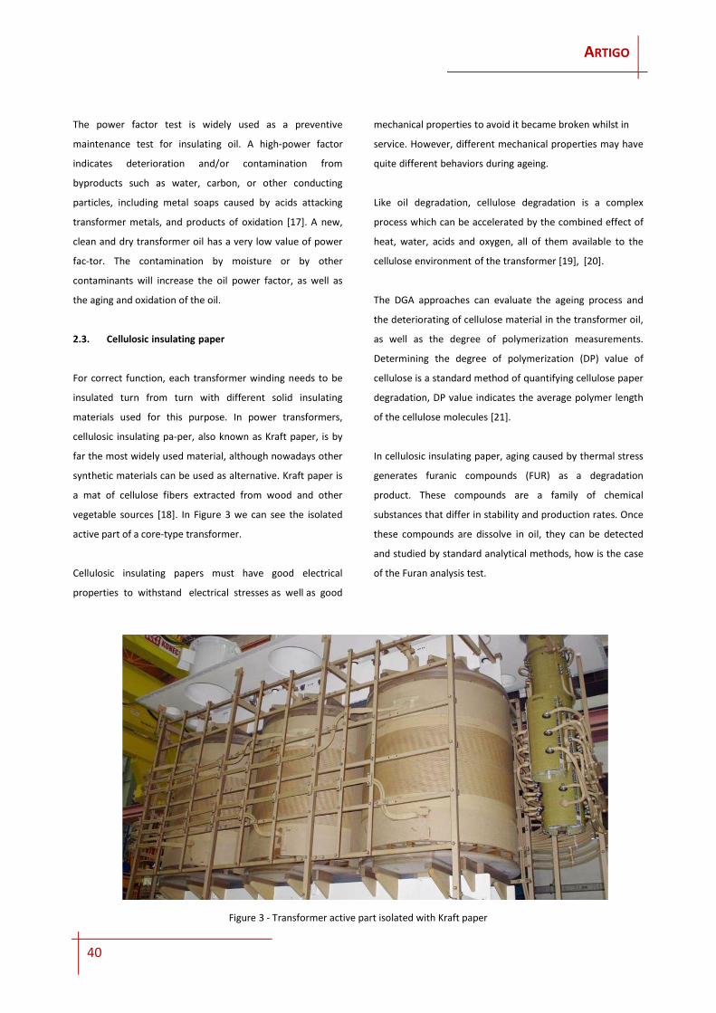
vegetable sources [18]. In Figure 3 we can see the isolated
active part of a core-type transformer.
Cellulosic insulating papers must have good electrical
properties to withstand electrical stresses as well as good
mechanical properties to avoid it became broken whilst in
service. However, different mechanical properties may have
quite different behaviors during ageing.
Like oil degradation, cellulose degradation is a complex
process which can be accelerated by the combined effect of
heat, water, acids and oxygen, all of them available to the
cellulose environment of the transformer [19], [20].
The DGA approaches can evaluate the ageing process and
the deteriorating of cellulose material in the transformer oil,
as well as the degree of polymerization measurements.
Determining the degree of polymerization (DP) value of
cellulose is a standard method of quantifying cellulose paper
degradation, DP value indicates the average polymer length
of the cellulose molecules [21].
In cellulosic insulating paper, aging caused by thermal stress
generates furanic compounds (FUR) as a degradation
product. These compounds are a family of chemical
substances that differ in stability and production rates. Once
these compounds are dissolve in oil, they can be detected
and studied by standard analytical methods, how is the case
of the Furan analysis test.
Figure 3 - Transformer active part isolated with Kraft paper

ARTIGO
41
2.4. Bushings and windings inspection
As seen, the condition of the oil and cellulosic paper
insulation is essential for secure and reliable operation of the
transformer. In addition to them, another import cause for
transformer outages is the replacement of bushings due to a
deterioration or failure of the insulation, they are one of the
major components causing forced outages of power
transformers.
Measuring capacitance and power factor/dissipation factor
are performed to investigate the condition of the insulation
in bushings or between windings. Changes in capacitance
indicate mechanical displacements of windings or partial
breakdown in bushings. By measuring the capacitance and
loss-es, problems in the insulation can be detected in an
early state, i.e., before a failure occurs.
Aging and degradation of the insulation, coupled with the
ingress of water, increase the amount of energy that is
converted to heat in the insulation. The rate of these losses
is measured by the dissipation factor, called tan (δ).
The dissipation factor is calculated via the tangent of the
angle δ between the measured current and the ideal current
which would occur if no losses would exist. The power factor
is the cosine of the angle φ, between the output voltage and
the measured current [22]. As seen in Figure 4, the dielectric
losses cause a phase shift.
Winding resistance measurements are performed for
assessing possible damage in windings or contact problems,
such as from the bushings to the windings and the windings
to the tap changer. They are also used to check the on-load
tap changer (OLTC) as they can indicate when to clean or
replace OLTC contacts, or when to replace or refurbish the
OLTC itself [22]. With this diagnostic tool, failures can be
detected without opening the tap changer compartment.
Static winding resistance measurements are the most
common and easiest way to check for issues regarding the
winding and OLTC. It investigates the resistance of each
subsequent tap position and compares it with the reference
measurement data of the manufacturer.
The requirements and tests for different categories of
windings carried out on each transformer should follow
IEC60076 standard [23].
Those dielectric tests performed on the transformer
bushings and windings evaluate the state of insulation
through the resistance insulation level and dissipation factor,
identifying possible leakage currents in the insulation
structure and can quantify its level of degradation.
The combination of these parameters with the oil analysis
and the insulation paper provide a very good diagnostic
methodology for the global assessment of the power
transformer. Therefore, optimizing the combination of
various diagnostic techniques is an important issue for the
calculation of the transformer status index.
Figure 4 - a) Phase shift b) Dissipation factor / Power factor

ARTIGO
42
3. STATE ASSESSMENT METHODOLOGY
In this work we develop a transformer state assessment
methodology, based on the calculation of a numerical
indicator, the status index - iET, which gives us a global
evaluation of the equipment and its current degree of
degradation. This indicator is calculated from five partial
indexes, three of them based on the analysis tests carried
out on the insulating oil and the other two, based on the
analysis of the dielectric tests on windings and bushings.
3.1. DGA index, iDGA – Oil Dissolved Gas Analysis
As seen previously, the dissolved gas analysis can provide a
reliable assessment about internal transformer faults.
Thermal and electrical failures generate typical fault gases
which are dissolved in the oil. The DGA index considers the
relative concentration and daily rate of change of the fault
gases, accordingly to their standards values.
3.2. FUR index, iFUR – Oil Furanic Compounds
Furaldehyde in oil is generated by the degradation of
cellulosic materials used in the solid insula-tion systems of
transformers. These compounds are oil soluble and leads to
migration into the insulating fluid so, high concentrations or
unusual increases concentrations in oil, may indicate
cellulose degradation from aging or another fault situation.
Direct measurement of these properties is not practical for
in-service transformers, however, the amount of furanic
compounds (2-FAL) is directly related to the degree of
polymerization (DP) of the paper inside the transformer. The
FUR index analyzes the level characterization of the
insulation paper degradation, directly related to the
equipment life expectancy.
3.3. AOL index, iAOL – Oil Physico-Chemical Properties
The insulating oil deteriorates gradually with use, loosing
slowly its dielectric and thermal proper-ties, by a series of
physical and chemical reactions.
The causes are the absorption of the moisture from air and
outer particles that get into the oil and cause oxidation,
decomposition and polymerization of insulation materials,
producing non-soluble particles collected in the coil and
windings. These sediments do not affect directly the
dielectric breakdown, but deposits formed on the winding,
hinder its normal refrigeration and accelerate the oil
oxidation. The AOL index analyses the concentration of
various oil parameters, indicative of natural oil degradation,
such as water and sediment content, color, acidity level and
disruptive voltage.
3.4. ATV index, iATV – Bushings Degradation
The aim of this index is to establish a classification of the
degradation level of the transformer capacitive bushings, by
directly measuring its dielectric dissipation factor values,
tg(δ), from both primary and secondary bushings, for a test
voltage of 10 kV.
3.5. AER index, iAER – Winding Degradation
Similarly, with this index we establish a classification of
degradation level of transformer windings, based on the
values from dielectric dissipation factor, tg(δ), applied with a
test voltage of 10 kV and the values from insulation
resistance at a test voltage of 5 kV during 10 minutes.
3.6. Transformer Status Index – iET
The transformer status index iET is obtained by weighing the
values of the five indexes, iDGA, iFUR, iAOL iATV and iAER,
getting the global indicator of the transformer state. The
indexes value weights vary according to the result of each
one, affording marked relevance to the priority cases, in a
way they are not masked by the calculation of mean values.
The equation (1) gives us the global state index:
(1)
iET = iDGA . KDGA + iFUR . KFUR + iAOL . KAOL + iATV . KATV + IAER . KAER

ARTIGO
43
Each of the Kx weighting values is obtained according to
equation (2):
(2)
where x represents any of the 5 previous parameters. For
instance, for the calculation of KDGA, equation (2) is
replaced by (3):
(3)
The weights Px take on values according to their specific
index, as seen in equation (4):
(4)
being T the maximum value of the index. In this study we
consider T=7, which are seven discrete ranks of classification,
ranging from 1 to 7, being 1 the best and 7 the worst. The
variable n is used as a decision variable for fine tuning the
calculation, allowing to linearly hold off all the weights
values, giving more relevance to higher weights in the final
equation of iET.
4. RESULTS AND ANALYSIS
The assessment methodology was applied to 241 in-service
power transformers from the Portuguese national grid. In
Figure 5, the results are sorted down by the transformer
state index. The number of transformers is higher in state
index level 2 and 3 (yellow zone), than those in level 1 (green
zone). This is expected since they are the first levels at which
evident degradation symptoms begin to appear, so this serve
as an indication of a warning.
We got more information from this sample, about 77% of
the analyzed equipment is in a positive state, the remaining
23% in a non-favorable state, with 2 transformers in a very
critical level, red zone in Figure 5.
The worst classified equipment is a three-phase 150/63 kV
power transformer with more than 35 years, actually
indicated for possible deactivation, due to an advanced
degradation of the insulation paper.
𝐾 =𝑃
𝑃 + 𝑃 + 𝑃 + 𝑃 + 𝑃
𝐾 =𝑃
𝑃 + 𝑃 + 𝑃 + 𝑃 + 𝑃
𝑃 = 1 + 𝑛. 𝑖 .1
∑ 𝑗
Figure 5 - Power Transformer ranking by state index

ARTIGO
44
The second most critical equipment is a 400/63 kV three-
phase transformer, operating for more than 25 years,
already indicated for reconditioning, due to an advanced
level degradation in oil and in the active part.
Another advantage of this methodology is the state
evaluation from the dynamic representation of the partial
state indexes and their standard limits, as seen in Figure 6.
The five partial indexes are represented by the central black
line, as well as their numerical classification. The lines
parallel to the center of the pentagon indicates the partial
indicators and the background colors indicate the limits of
degradation degrees. The final indicator is on the vertical
axis of the polygon and it position depends on their value.
5. CONCLUSION
In this work it was made a diagnostics of transformer
equipment, as well as the state indexes analysis. The study
proposes a methodology to evaluate the global state of the
power transformers in the electrical grid, based on five
partial indexes values, three of them from tests carried out
on the insulating oil and other two, from dielectric tests on
windings and bushings.
The state assessment methodology provides important
information about the transformer compo-nents condition
in-service and constitute an important decision support to
stablish the hierarchy of maintenance activities. Thus, it is
possible to identify the degradation degree of some specific
equipment, allowing preventive measures to be taken
accordingly.
The methodology was applied in real case equipment, with
an exhaustive analysis of 241 trans-formers on service in
Portuguese national electric grid. With this study it becomes
possible, not only a statistical analysis of historical data, but
also it can anticipate trends and establish cause-effect
relationships upon the different parameters and their
operation work conditions.
Figure 6 - Power Transformer state index assessment tool

ARTIGO
45
REFERENCES
[1] U.S. Department of Energy, "An Assessment of Energy
and Research Opportunities," in Enabling
Modernization of the Electric Power System.:
Quadrennial Technology Review, 2015.
[2] Mario Willms, Power Engineering Guide. Alemanha:
Siemens Aktiengesellschaft, 2014.
[3] Stefan Tenbohlen, Sebastian Coenen, Mohammad
Djamali, and Andreas Müller, "Diagnostic
Measurements for Power Transformers," Energies, p.
25, 2016.
[4] Patricia Hoffman and William Bryan, "Large Power
Transformers and the U.S. Electric Grid," U.S.
Department of Energy, 2012.
[5] Industrial Technology Review, "Right Choice of Dry
Type or Liquid-Filled Transformer," Electrical, vol. nº
280, 2017.
[6] Jean Sanchez and Mladen Banovic, "Basics of Power
Transformers," Transformers Magazine , vol. 1, no. 1,
pp. 22-25, 2015.
[7] ABB, "Operation and Maintenance for Power
Transformers," User's Manual 1ZCL000002EG-EN, 2007.
[8] Radu Godina, Eduardo Rodrigues, João Matias, and
João Catalão, "Effect of Loads and Other Key Factors on
Oil-Transformer Ageing: Sustainability Benefits and
Challenges," Energies, vol. 8, no. open access, pp.
12147-12186, 2015.
[9] CIGRE, "Ageing cellulose in mineral oil insulated
transformer," Brochure 323 TF D1.01.109, 2007.
[10] Sung Wook Kim, Sung-jik Kim, Hwang-dong Seo, and
Michel Duval, "New Methods of DGA Diagnosis using
IEC TC 10 and Related Databases Part 1: Application of
Gas-ratio Combinations," IEEE Transactions on
Dielectrics and Electrical Insulation, vol. 20(2), pp. 685-
690, April 2013.
[11] IEC60296, "Fluids for electrotechnical applications -
Unused mineral insulating oils for transformers and
switchgear," 2012.
[12] IEEE, "Guide for the Interpretation of Gases Generated
in Oil Immersed Transformers," New York, NY, USA,
IEEE Std. C57.104 2008.
[13] Jae Ryong Jung, H D Seo, S J Kim, and Sung Wook Kim,
"Advanced Dissolved Gas Analysis (DGA) Diagnostic
Methods with Estimation of Fault Location for Power
Transformer Based on Field Database," in CIGRE 2016,
vol. A2-106, France, 2016.
[14] R. Anderson, U.R. Roderick, V. Jaakkola, and N. Östman,
"The Transfer of Fault Gases in Transformers and Its
Effect upon the Interpretation of Gas Analysis Data,"
Paris, France, Cigré Report 12-02 1976.
[15] E. Bräsel, O. Bräsel, and U. Sasum, "Gashaushalt bei
Transformatoren der offenen Bauart—Neue
Erkenntnisse," in EW-Medien und Kongresse,
Frankfurt, Germany, 2010, pp. 56-59.
[16] Paul Gill, Electrical Power Equipment Maintenance and
Testing. USA: CRC Press, 2014.
[17] Hydroelectric Research and Technical Services Group,
"Transformer Diagnostics," USA, 2003.
[18] C. Fernández, F. Ortiz, C. Olmo, J. Carcedo, and A. Ortiz,
"Assessment of the temperature distribution into a
transformer through tensile," RE&PQJ - Renewable
Energy and Power Quality Journal, vol. 1, no. 14, pp.
720-724, May 2016.
[19] CIGRE DI 143, "Insulating Oil Regeneration and
Dehalogenation," Working Group D1.01 (TF 12) ISBN:
978-2-85873-100-8, 2010.
[20] A. De Pablo et al., "Furanic compounds analysis as a
tool for diagnostic and maintenance of oil-paper
insulation systems," in CIGRE Symposium on Diagnostic
and Maintenance techniques, Berlin, 1993, pp. Paper
110-09.
[21] Huo-Ching Sun, Yann-Chang Huang, and Chao-Ming
Huang, "A Review of Dissolved Gas Analysis in Power
Transformers," Energy Procedia , pp. 1220-1225, 2012.
[22] OMICRON, "Testing and diagnostics of power
transformer," OMICRON L2673, OMICRON L2673,
December 2016.
[23] IEC60076, "Power transformers – Part 3: Insulation
levels, dielectric tests and external clearances in air,"
2000.