SINGLE PHASE TRANSFORMERS 2012 13 2Q
71
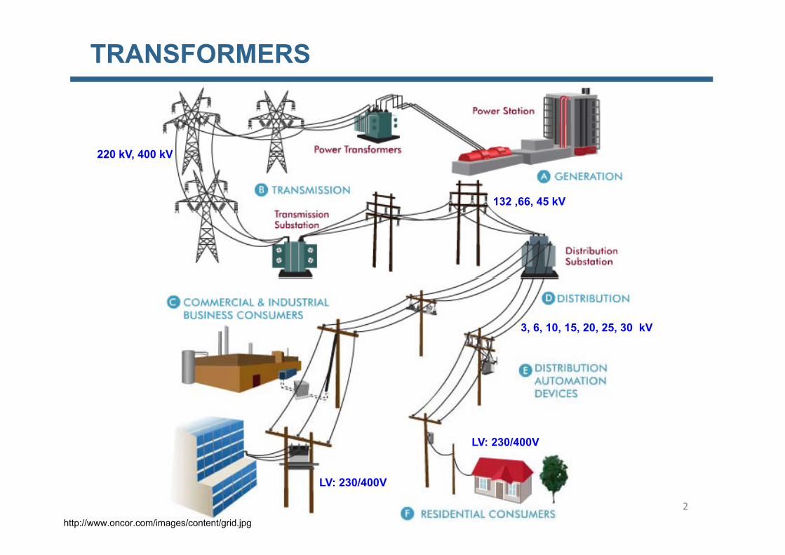
TRANSFORMERS Transmission of energy is generally divided in two parts; first is transmission INTRODUCTION over long distances at high voltages, which is supported by Power Transformers. The second part is distribution of the energy from substations to the various users; this is supported by Distribution Transformers in various hierarchies. 1
Transcript of SINGLE PHASE TRANSFORMERS 2012 13 2Q

TRANSFORMERS
Transmission of energy is generally divided in two parts; first is transmissionINTRODUCTION
over long distances at high voltages, which is supported by PowerTransformers. The second part is distribution of the energy from substations tothe various users; this is supported by Distribution Transformers in varioushierarchies.
1
TRANSFORMERS
220 kV 400 kV220 kV, 400 kV
132 ,66, 45 kV
3, 6, 10, 15, 20, 25, 30 kV
LV: 230/400V
LV: 230/400V
http://www.oncor.com/images/content/grid.jpg
2
TRANSFORMERSRATED VOLTAGE (kV)Overhead power lines
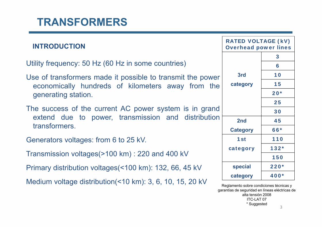
3 Utility frequency: 50 Hz (60 Hz in some countries)
INTRODUCTION
6 3rd 10
category 15
Utility frequency: 50 Hz (60 Hz in some countries)
Use of transformers made it possible to transmit the powereconomically hundreds of kilometers away from the
20* 25 30
economically hundreds of kilometers away from thegenerating station.
The success of the current AC power system is in grand2nd 45
Category 66*
1st 110
extend due to power, transmission and distributiontransformers.
Generators voltages: from 6 to 25 kV 1st 110
category 132* 150
i l 220*
Generators voltages: from 6 to 25 kV.
Transmission voltages(>100 km) : 220 and 400 kV
P i di ib i l ( 100 k ) 132 66 45 kV special 220* category 400*
Reglamento sobre condiciones técnicas y garantías de seguridad en líneas eléctricas de
Primary distribution voltages(<100 km): 132, 66, 45 kV
Medium voltage distribution(<10 km): 3, 6, 10, 15, 20 kV
3
garantías de seguridad en líneas eléctricas de alta tensión 2008
ITC-LAT 07 * Suggested

TRANSFORMERS
Transformer: static device that transfers electrical energy from one circuit toanother by electromagnetic induction without the change in frequency It
INTRODUCTION
another by electromagnetic induction without the change in frequency. Itchanges the relationship between voltage and current in primary andsecondary sides.
It is made of steel laminations wrapped with two coils of wire.
Winding connected to source named “Primary”Winding connected to source named Primary
Winding connected to load named “Secondary”
4

TRANSFORMERS
The transformer is an electromagnetic conversion device which has a primaryand a secondary windings. It accomplishes: V1I1 ≈ V2I2.
The primary and secondary windings are not connected electrically, butcoupled magnetically.
Machines with higher efficiency, up to 99.7%
Step-up transformer: U2>U1 I2<I1 Step-down transformer: U1>U2 I1<I2 Isolation transformer: U1=U2 I1=I2
5

TRANSFORMERS
Rating: The nominal value of any electrical, thermal, mechanical, or environmental quantity assigned to define the operating conditions under which
t hi t l t i d i t i t d t ia component, machine, apparatus, electronic device, etc., is expected to give satisfactory service.
Rated freq enc (f ) The freq enc of the alternating c rrent for hich aRated frequency (fn): The frequency of the alternating current for which a device is designed.
Rated continuous current (I ): The current expressed in amperes root meanRated continuous current (In): The current expressed in amperes, root mean square RMS, that the device can carry continuously under specified service conditions without exceeding the allowable temperature rise.
Rated voltage: The RMS voltage, at rated frequency, which may be impressed between the terminals of the device under standard operating conditions.
6

TRANSFORMERS
Power loss generate heat
Dry transformers: for low powerDry transformers: for low power
Oil-filled transformers: for large power, the transformer is completely submerged in an oil tank The oil actuates as a coolant and an insulator Mineral oil (froman oil tank. The oil actuates as a coolant and an insulator. Mineral oil (from distillation of petrol) and silicone oil (most actual)
Dry-type transformers encapsulated in epoxy resin: for installations that requireDry type transformers encapsulated in epoxy resin: for installations that require high security, specially in indoor. They don’t spread fire. High voltage windings are completely encapsulate in epoxy resin.
Oil insulated type transformer 33 kV to 400 V
Dry type transformer 33 kV to 400 V
25 KVA - 20 MVA Refrigeration: mineral oil a
low flammability synthetic fluid
40 KVA - 5 MVA Insulation: epoxy resin Ventilation
fluid Ventilation (possibility)
Kotsons Catalogue
Indoor Very safeKotsons Catalogue
7

TRANSFORMERS
Insulation Symbol Type of i l ti
Symbol
REFRIGERATION SYSTEMS
circulation
Mineral oil O Natural N
Pyralene L Forced F
Gas G
Water W
Air AAir A
Solid insulation S
ONAN: Oil Natural (transformer submerged in an oil tank; oil with natural convection).It is refrigerated by Air with Natural convection
ONAF: In this case the Air is Forced by means of a fan
8

TRANSFORMERS
ENERGY LOSSES
1. Winding losses : I2 R
2. Iron losses:2. Iron losses:2.1 Hysteresis2.2 Eddy currents (Foucault currents)
9

TRANSFORMERSENERGY LOSSES
Hysteresis loopStarting from zero we gradually increase I [A] so that H [A m] and B [T]Starting from zero, we gradually increase I [A] so that H [A m] and B [T]increase, curve 0a, the flux density reaches a value Bm for a magnetic fieldintensity Hm. If the current is now gradually reduced to zero, the flux density Bdoes not follow the original curve but moves along a curve abdoes not follow the original curve, but moves along a curve ab.
As we reduce the magnetic field intensity, the magnetic domains that werelined up under the influence of field Hm tend to retain their original orientation.This phenomenon is called hysteresis
10
This phenomenon is called hysteresis.There is a frictional resistance of the magnetic domains, so the energysupplied is dissipated as heat in the material.

TRANSFORMERS
ENERGY LOSSESHysteresis lossThe ac current causes the flux in the iron changes continuously both in valueand direction. The magnetic domains are therefore oriented first in one directionand then the other, at a rated that depends on the frequency. Thus if the fluxhas a frequency of 50 Hz, the domains describe a complete cycle every 1/50 s.In describing a hysteresis loop, the flux moves successively from +Bm, +Br,, -Bm,-Br, o, and +Bm.
Hysteresis loop. If B is expressed in teslas and H in amperes per meter, the p p ,area of the loop is the energy dissipated per cycle, in joules per kilogram.Energy lost in moving the domain walls as the magnet is poled from one extreme to the other and back again.
]/[2max KgWBfkP hhysteresisfe
11

TRANSFORMERS
ENERGY LOSSES
Hysteresis lossHysteresis loss
The magnetic material absorbs energy during each cycle and this energy isdissipated as heatdissipated as heat.
To reduce hysteresis losses, we select magnetic materials that have a narrow hysteresis loop such as the grain oriented silicon steel used in the cores ofhysteresis loop, such as the grain oriented silicon steel used in the cores of transformers.
B Soft (electrical steel)
Hard (permanent magnet)
H
12
TRANSFORMERS
ENERGY LOSSES
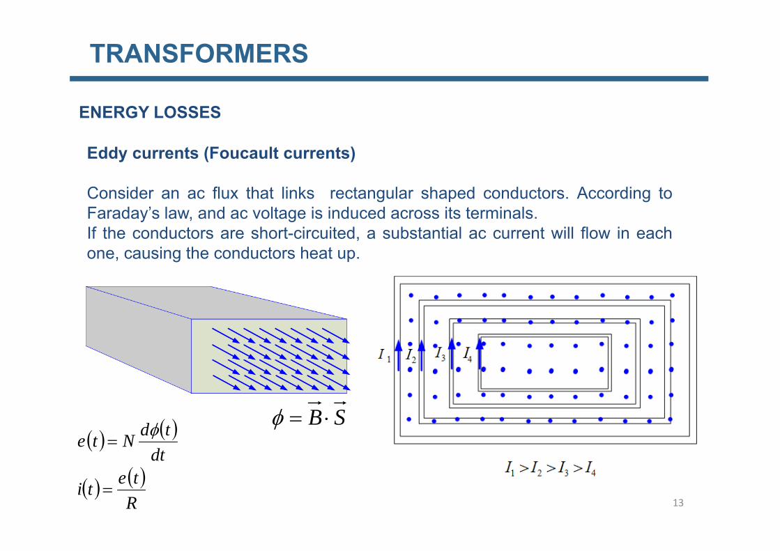
Eddy currents (Foucault currents)Eddy currents (Foucault currents)
Consider an ac flux that links rectangular shaped conductors. According toFaraday’s law and ac voltage is induced across its terminalsFaraday s law, and ac voltage is induced across its terminals.If the conductors are short-circuited, a substantial ac current will flow in eachone, causing the conductors heat up.
SB
dttdNte
13
Rteti

TRANSFORMERS
Eddy currents (Foucault currents)ENERGY LOSSES ]/[2
max22 KgWBdfkP ecurrentseddyfe
The solid metal plate is basically equivalent to a densely packed set ofrectangular conductors touching each other. Currents swirl back and forthi id th l t Th ll d dd t F lt t binside the plate. These are so-called eddy currents or Foucault currents, can bevery large, due to the low resistance of the plate, thus the metal plate canbecome very hot. In this regard, special care has to be taken.
dAB
The losses can be reduced by splitting the core and insulating the twosections from each other
S
sections from each other.Currently the lowest thickness available is 0.23 mm, and the popular thicknessrange is 0.23 mm to 0.35 mm for power transformers. 14

TRANSFORMERS
Transformer cores are built from thin sheets of steel.
CORE MATERIALS
Core steel is alloyed with silicon (Si). Silicon increases the specific electricalresistance, which again reduces the eddy current losses in the core.Increased silicon content makes the core steel brittle; therefore the content is keptbelow 3%.To minimize eddy current losses, the sheets must be insulated from eachother. Today the core steel is delivered ready insulated from the manufacturer.Th i l ti ti i thi 4The insulating coating is very thin < 4 μm.
Eddy current losses in the core steel are proportional to the square of thethickness Therefore the steel sheets have to be thin in order to reduce the nothickness. Therefore the steel sheets have to be thin in order to reduce the noload losses. Typical thickness is from 0.23 mm to 0.35 mm.
15

TRANSFORMERS
MAGNETOSTRICTION
The dominant generating source of transformer sound is magnetostriction.
Magnetostriction is the change in dimensions which takes place in certaint i l h th bj t d t h i ti fl I timaterials when they are subjected to a change in magnetic flux. In magnetic
core steel the dimensional change is in the range of 10-7 to 10-5 meters permeter length at typical induction levels.
This produces the buzzing sound commonly associated with transformers andin turn causes losses due to frictional heating in susceptible cores.
16

TRANSFORMERS
CORE MATERIALS
17Standard IEC specification for nonoriented magnetic steel sheet

TRANSFORMERS
CORE MATERIALS
Standard IEC speci cation for grain oriented magnetic steel sheet (a) normal material; (b) material with reduced
18
Standard IEC speci.cation for grain-oriented magnetic steel sheet. (a) normal material; (b) material with reducedloss; (c) high-permeability material.

TRANSFORMERS
19

TRANSFORMERS
IDEAL TRANSFORMER AT NO LOAD
Supposing ideal coil t
021 RR
Supposing ideal coil
)( tu
)(0 ti
)(2 te )(2 tu
t
)(t
0)(2 ti
tute
)(1 tu )(2)(1 te
dt
tdNte
tetu
11
11
ttdt
tdNte
tute
22
22
sin
fNNtNtetu
tt
m
m
111
2cos
sin
fNfNNU
tNtetutt
mm
m
m
222
2
222
4442cos
sin
fSBNU
fNfNNU mmm
111
1
444
44.422
2
fSBNU
fNU
m
m
22
22
44.4
44.422
fSBNU m11 44.4 m22
tet rUU
NN
EEr
20
1
2
1
2
120

TRANSFORMERS
IDEAL TRANSFORMER AT NO LOAD WITH LINEAR WITH LINEAR B-H CURVE
200
250
v1v2fluxi0
50
100
150 i0
-50
0
50
-150
-100
0 0.005 0.01 0.015 0.02 0.025 0.03 0.035 0.04-250
-200
t [s]
[ ]
21

TRANSFORMERS
No load current Hysteresis not consideredIDEAL TRANSFORMER AT NO LOAD WITH NONLINEAR B-H CURVE
u
SB
1u
tetu
tutu cos
11
max1
t0i
ttdt
tdNte
m
sin
11
22
0

TRANSFORMERS
[A]No load current Hysteresis considered
TRANSFORMER AT NO LOAD WITH NONLINEAR B-H CURVE
oad
curr
ent [
No
lo
u
SB
t [ms]1u
Core Losses
fePfe
23t0i

TRANSFORMERS
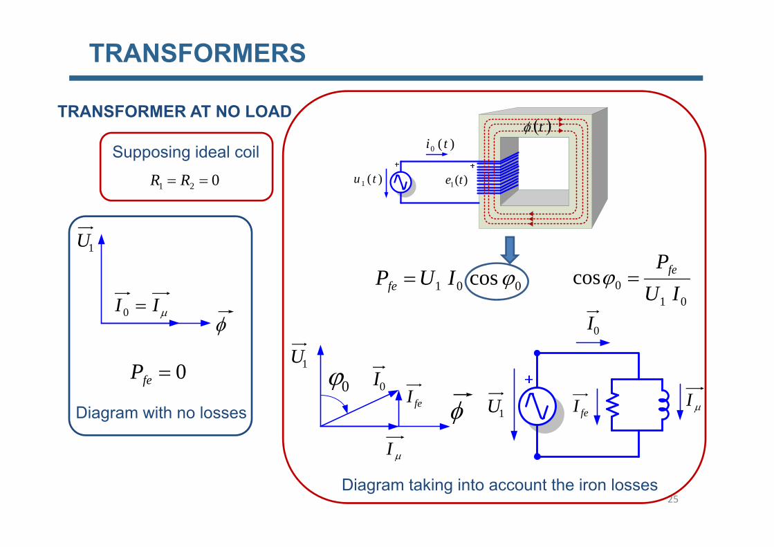
TRANSFORMER AT NO LOAD
The no-load current is not sinusoidal
T k ith h d it t b i idTo work with phasors we need it to be a sinosoid
An equivalent sinosoid is defined with the same RMS value that the real no load current to perform the calculations and in such a way that it cause theload current to perform the calculations and in such a way that it cause the same core losses:
PfefeP
010cos
IUfe
24
TRANSFORMERS
TRANSFORMER AT NO LOAD
)(0 ti t
Supposing ideal coil)(1 tu
)(0
)(1 te021 RR
Supposing ideal coil
IUPPfe
1U
001 cosIUPfe
0I01
0cosIU
feII 0
I0feP 1U
I0I0
Diagram with no losses feI I1U
I
feI
25Diagram taking into account the iron losses

TRANSFORMERS
TRANSFORMER AT NO LOAD
and
01 R
Leakage flux
101011 EIXjIRU d 26
TRANSFORMERS
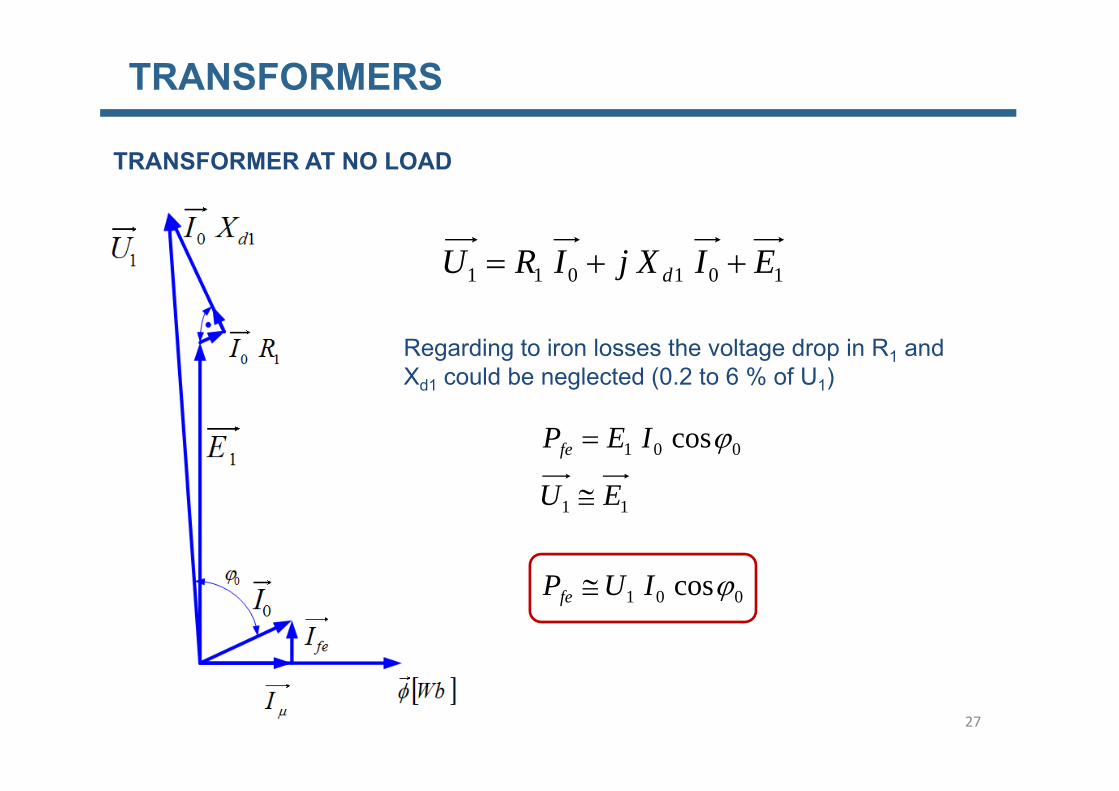
TRANSFORMER AT NO LOAD
101011 EIXjIRU d
Regarding to iron losses the voltage drop in R1 and Xd1 could be neglected (0.2 to 6 % of U1)
001 cos
EU
IEPfe
11 EU
001 cosIUPfe
27

TRANSFORMERS
TRANSFORMER UNDER LOAD
If this was so, the flux would increase, which it is no possible due to the Lenz law
td
possible due to the Lenz law.
dt
tdNte 22
28

TRANSFORMERS
TRANSFORMER UNDER LOAD
dt
tdNte 22
29

TRANSFORMERS
TRANSFORMER UNDER LOAD
30

TRANSFORMERS
Can I do it?
TRANSFORMER UNDER LOAD
Can I do it?
31

TRANSFORMERS
A-aA’-a’
TRANSFORMER UNDER LOAD
32

TRANSFORMERS
TRANSFORMER UNDER LOAD
33

TRANSFORMERS
TRANSFORMER UNDER LOAD
t tbt
dt
tdNtetu
systempowerthebyfixedtutu
cos
111
max1
01
tan;
loadnoIN
tconsbemust
ttdt
m sin
221101
2211
INININ
loadunderININ
220111
221101
NINININ
21
201 I
NNII
34

TRANSFORMERS
2N
TRANSFORMER UNDER LOAD t
)(2 ti tititi ')()(
22
21
201
' IINI
INNII
)(2 te )(2 tu
)(2 ti
)(1 tu
tititi ')()( 201
)(1 te
2221
22
1
22
'
'
ININ
rI
NI
t
'2012
021
201 III
rIII
NNII
t
1 t
111111 EIXjIRU d
222222 UIXjIRE d
35222 IZU

TRANSFORMERS
TRANSFORMER UNDER LOAD
11 NE)(2 te )(2 tu
)(2 ti
)(1 tu
)(1 ti
)(1 teIt is always true
2
1
2
1
; EUEU
NEr et
XI
It is always true
11
2211 ;
UEr
EUEU
2E RI
22 dXI1U
11 RI
11 dXI
202 UEr et
2U22 RI
1EWhen
2I2
1I1'2I
When
nn UUthenUUIf 22011
0I
2
n
nt U
Ur2
1
36

TRANSFORMERS
EQUIVALENT CIRCUIT REFERED TO THE PRIMARY
222222
111111
UIXjIRE
EIXjIRU
d
d
222222
rEIXjIRU
UIXjIRE d
trEE 21
''' 22222222222222
211111
rUrIXjrIRrErIIrUIXjIRrE
rEIXjIRU
ttdttttdt
td
'''
''22
222
222
211111
UUXXRR
rUIrXjIrRIXjIRU ttdtd
''''''
''' 222
222
22 rUUrXXrRR ttddt
37
'''''' 2012222211111 IIIUIXjIRIXjIRU dd

TRANSFORMERSEQUIVALENT CIRCUIT REFERED TO THE PRIMARY
'2I
+
1I
'2U1U
+
1E 12' EE '21 NN
'2I1I
+
'2U
+
1U
+1E 2'E'21 NN
'X 'R
+
trII 2
2 ' trUU 22 '
1U
2dX 2dR1dX1R
'201 III
1U221 ' ErEE t
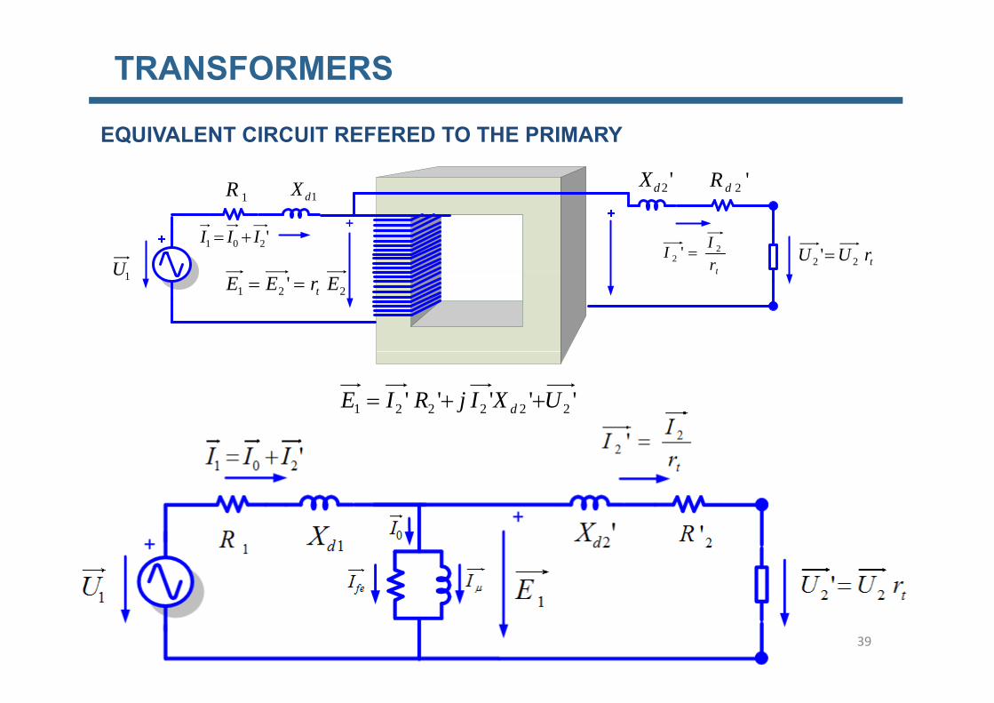
TRANSFORMERS
EQUIVALENT CIRCUIT REFERED TO THE PRIMARY
'2dX '2dRXR
+
trII 2
2 ' trUU 22 '
U
1dX1R
'201 III
t1U221 ' ErEE t
''''' 222221 UXIjRIE d
39

TRANSFORMERS
EQUIVALENT CIRCUIT REFERED TO THE PRIMARY
40

TRANSFORMERS
Exact equivalent circuit
EQUIVALENT CIRCUIT REFERED TO THE PRIMARY
Exact equivalent circuit
Approximate equivalent circuit, since Rfe>>R1 & R2, X>>X1&X2
41

TRANSFORMERS
EQUIVALENT CIRCUIT REFERED TO THE PRIMARY
Approximate equivalent circuit,
'21 II
jXRIUU ''42
'21110 IIII scsc jXRIUU 11221 ''

TRANSFORMERS
EQUIVALENT CIRCUIT REFERED TO THE SECONDARY
EIXIRU
222222
111111
UIXjIRE
EIXjIRU
d
d
222221 UIXjIR
rE
dt
2222211111 UIXjIR
rIXjIRU
dt
d
2101 r
IIIt
21011 ' IrIIrI tt
4321
1221
122
1 UrrI
rXjIXj
rrI
rRIR
rU
t
t
t
dd
t
t
tt
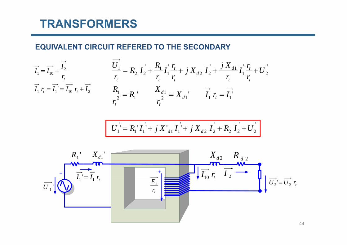
TRANSFORMERS
111 rXjrRU d
EQUIVALENT CIRCUIT REFERED TO THE SECONDARY
I
11
211
2211
221
''' IrIXXRR
UrrI
rXjIXj
rrI
rRIR
rU
d
t
t
t
dd
t
t
tt
21011
2101
' IrIIrI
rIII
tt
t
111212 IrIXr
Rr td
tt
2222211111 ''''' UIRIXjIXjIRU dd
+
2dX 2dR'1dX'1R
rII ' 2ItrI10
trUU 22 ''1U
trII 11
trE1
t10
44

TRANSFORMERSEQUIVALENT CIRCUIT REFERED TO THE SECONDARY
2I2101 '' III
+
2U
'10I
E'1U
'1R '1dX 2X 2R
2Utr
EEE 121 ' 1U
2222211111 ''''' UIXjIRIXjIRU dd
trII 12 ' RRR ' XXX
2I
t12 212 RRR sc 212 XXX sc
2I2U
trUU 1
1' 2Z
45 scscsc jXRXXjRRZ 2221212 '' scsc jXRIUU 22221'

TRANSFORMERS
EQUIVALENT CIRCUITS SUMMARY
'XXX 1I 'RRR 1:tr
II 2'0I
211 XXX sc 211 RRR sc 2I
t
trI 2
2 ' trUU 22 '
IfeI1U 2U
' XXXII ' ' RRR1:r1I
trI 0
212 ' XXX sc trII 11 '212 ' RRR sc 1:tr1I
1U 2U2I
trU1
46

TRANSFORMERSVOLTAGE DROP
An example of how the secondary voltage
scsc jXRIUU 11221 '0'
p y gvaries with various angles of and loadcurrents for the particular values ofRcc= 0.74 % and Xcc=10%. Negativesvalues of mean inductive load current.Positive values mean capacitive loadcurrent.
Another example of how the secondary
scsc jXRIUU 11221 '0'
p yvoltage at rated current may vary atvarious values of Xcc and cos . Ingeneral secondary voltage decreases withg y gincreasing Xcc. For example at Xcc=10%and cos =0.8 the secondary voltage hasdropped to 93 % of the no load voltage.
47Xcc % scsc jXRIUU 11221 '0'
TRANSFORMERS
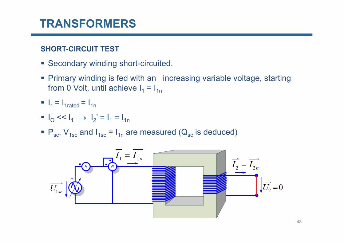
Secondary winding short-circuited.
SHORT-CIRCUIT TEST
y g
Primary winding is fed with an increasing variable voltage, starting from 0 Volt, until achieve I1 = I1n
I1 = I1rated = I1n
IO << I1 I2’ = I1 = I1nO 1 2 1 1n
Psc, V1sc and I1sc = I1n are measured (Qsc is deduced)
48

TRANSFORMERS
SHORT-CIRCUIT TEST
The test voltage U1sc very low, it will be few flux, so that the iron losses can be neglected, Pfe=k Bm
2.
Results from the test:
Losses in the cupper:
Circuit parameters: R1sc=R1+R2’ and X1sc=X1+X2’ 49

TRANSFORMERS
SHORT-CIRCUIT TEST
A) Why losses in the iron, Pfe, can be neglected?
50

TRANSFORMERS
A) Why losses in the iron P can be neglected?
SHORT-CIRCUIT TEST
A) Why losses in the iron, Pfe, can be neglected?
cosmax1 td
tutu
44.4sin 11
111
mm SBfNUttdt
tdNtetu
%5%5
11 nmn
BUUBtutu
%5%5
2
11
nmnsc
BkP
BUU
4001
400105.0 1
221
nfenmnmscfe
mfe
UPBkBkUP
BkP
01 scfe UP 51

TRANSFORMERS
SHORT-CIRCUIT TEST
11 cos ccnscsc
PIUP
21
1
scscsc
n
scsc
tgPQX
IPR
21
21
1nn
sc IIX
52

TRANSFORMERS
SHORT-CIRCUIT TEST
What happens if we do this test with another U1 in such a way that does notWhat happens if we do this test with another U1sc in such a way that does not produce the rated current ?
scnnsc RIIP 12
11
scscsccunsc RIIPthenIIIf 12
1111 2
1
111
n
scnscsccu I
IIPIP
scn
scsc
nsc
sccu
RIRI
IPIP
12
1
12
1
1
1
1 n
53

TRANSFORMERS
SHORT-CIRCUIT TEST
22211
11111
XscRscscXscRscsc
nscnscsc
UUUUUU
IjXIRU
111 ccnscsc
scscscscscsc
UZI
UU
1
11
1
1
11
scnRscRsc
nnsc
URI
UU
UU
1
11
1
1
11
n
scn
n
XscXsc
nn
UXI
UU
UU
IUP222
XscRscsc
ccnscsc IUP cos11
54

TRANSFORMERS
SHORT-CIRCUIT TEST
(%)CC (%)XCC (%)RCC XCCRCC
Transformers < 1000 kVA 3 ÷ 6 2,5 ÷ 6 1,1 ÷ 2,5 1,2 ÷ 6
Transformers > 1000 kVA 6 ÷ 13 5 ÷ 13 0,4 ÷ 13 3 ÷ 30
55
TRANSFORMERS
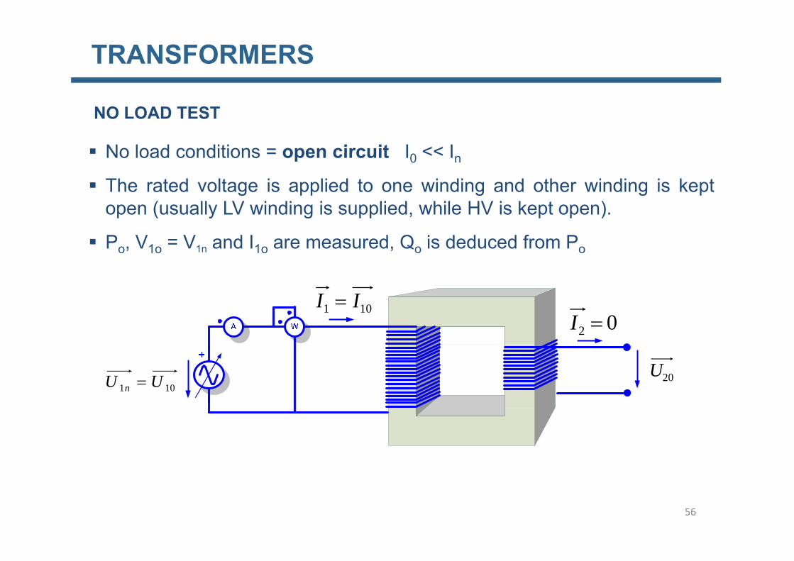
NO LOAD TEST
No load conditions = open circuit I << I No load conditions = open circuit I0 << In The rated voltage is applied to one winding and other winding is kept
open (usually LV winding is supplied, while HV is kept open).p ( y g pp , p p )
Po, V1o = V1n and I1o are measured, Qo is deduced from Po
101 II 02 I
101 UU n 20U
56

TRANSFORMERS
NO LOAD TEST
Results from the test:
Losses in the iron:Losses in the iron:
Circuit parameters: Rfe and Xµ 57

TRANSFORMERS
NO LOAD TEST
22 UU
010100
0101010100
sincoscos
IUQIUIUP n
00
10
0
10
tgPUX
PURfe
110 EU
210UR
210
12
00
10fe
UX
RIPR
58
12
000 dXItgPX

TRANSFORMERS
What happens if we do this test with another U10 which is NOT U1 ?
NO LOAD TEST
What happens if we do this test with another U10 which is NOT U1n ?
2
102
01
nhmfe
nfe
UkPBkP
PUP
2
1
UPUP
2
111
2111
hnfe
hnfe
UkUUP
UkUUP
1
101
n
fe UPUP
21
1
0 nh
hf
UkP
59
TRANSFORMERS
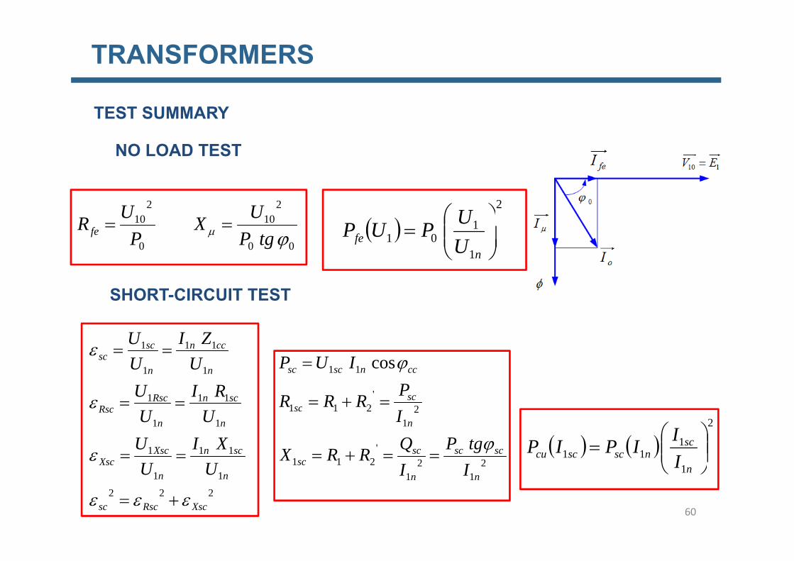
TEST SUMMARY
NO LOAD TEST
2
U
NO LOAD TEST
210
210 UU
1
101
nfe U
UPUP00
10
0
10
tgPUX
PURfe
SHORT-CIRCUIT TEST
111 ccnsc ZIU
111
1
11
1
1
scnRscRsc
n
ccn
n
scsc
RIUUU
U
2'
211
11 cos
scsc
ccnscsc
PRRR
IUP
2
1
111
n
scnscsccu I
IIPIP111
11
scnXscXsc
nnRsc
UXI
UU
UU
22'
211
21
211
scscscsc
nsc
ItgP
IQRRX
I
60
1 n
22211
XscRscsc
nn UU
11 nn II

TRANSFORMERS
FERRANTI EFFECT
nUU 22
61

TRANSFORMERS
The efficiency of a transformer is defined as the ratio of useful output power to
EFFICIENCY OF THE TRANSFORMER
y p pinput power
out
PPPP
PP
PP 22
2
101
feUPUP
nn
cufein
indexloadII
IIC
PPPPP
1
1
2
2
21
2
I
1
01
n
fe U
nn
PCUPIU
IU
22
1022
22
12
cos
cos
1
111
n
scnscsccu I
IIPIP
Maximizing the efficiency with respect to C, it results:
scn
PCU
PIU1
022 cos
fe
PP
C maxcuP
62

TRANSFORMERS
SHORT CIRCUIT CURRENTS
nsc I
UZ 1sc
sc I
UU1
sc
nsc I
UZ1
1
sc
n
n
sc
IU
IU 1
1
1 n
scsc I
UZ1
1
nnnsc
IUUII 11
1
scn1
scscnsc U 1
1
5<ε<10% h t i it t 10 20 ti I i bt i d5<ε<10% a short circuit current 10 or 20 times I1n is obtained
63

TRANSFORMERS
TRANSFORMERS IN PARALLEL
1.-If rt A= rt B we have the following schemet A t B g
If I0T<<I2T’ then I1T=I2T64

TRANSFORMERS
TRANSFORMERS IN PARALLEL
''' 212121 BBSCAASC IZIZUU
65

TRANSFORMERS
BBSCAASC IZIZUU 212121 '''TRANSFORMERS IN PARALLEL
BABSCBSCAAASCASC IZIZ 221221 ''
BBSCAASC
ICIIC
IZIZ
2
2121
''
''
nSCnSC
nn
UZIZ
ICII
C
111
121
2 ';
nSCBnSCA
n
nSCSC
nSC
ICUICU
IZ
U
11
1
11
1
;
nBBnB
nSCBnAA
nA
nSCA ICI
ICI
11
11
1
1
SCBBSCAA CC 66

TRANSFORMERS
221221 '' BABSCBSCAAASCASC IZIZ '' IZIZ
TRANSFORMERS IN PARALLEL
22 BBSCAASC
2121 ABSCAASC IZIZ
22 ASCBSCAB
22 ABASCBSC
It can be noted that the currents in each transformer are in phase, so that it can be added arithmetically instead of vectorially.
'''''' IIIIII ...... 222222 BATBAT IIIIII
67

TRANSFORMERS
TRANSFORMERS IN PARALLEL TRAFO Sn [kVA] εsc (%)
A 100 4.5We have the following transformers, fed at rated voltageB 1000 5.5
g g
Which will be the total available aparent power (VA) ?
SCBBSCAA CC
CSSCIUIUS
CC
C
5554
10CSSCIUIUSCSSCIUIUS
BnBBBnBnBBnBB
AnAAAnAnAAnAA
ABA
BA
CC
CCCCC
81805.45.41
5.55.4
kVAkVASkVAkVAS
B
A
818818.010001001100
AB
IUSS
CC
818.05.55.5
kVAkVAkVAST 918818100 !!
nnn IUSS max
68

TRANSFORMERS
INRUSH CURRENT
tUtu
iftUtu
cos2
º0cos2
11
11
200
300
TT
dttUNddttUNd
tUdt
tdNtetu
cos2cos2
cos2
4/4/
1111
-100
0
100
u [V
]
TU
ifand
dttUNddttUNd
i
00
cos2cos20
110
11
0 0.005 0.01 0.015 0.02-300
-200
t [s]
mfN
UfN
UN
UN
UT
44.4220sin4
sin2
4 1
1
1
1
1
1
1
1
69

TRANSFORMERS
tUtu
if
º90cos2
º90INRUSH CURRENT
TTTT
dttUNddttUNd
tUtu
sin2º90cos2
º90cos22/
011
2/
0
2/
011
2/
0
11
mNU
NUUT
TNUT
ifand
2221120cos2
2cos22
00
1
1
1
11
1
1
200
300
-200
-100
0
100
u [V
]
0 0.005 0.01 0.015 0.02-300
t [s]
70

TRANSFORMERS
INRUSH CURRENT
The light grey curve is theThe light grey curve is themagnetic flux in the normalstationary condition
In practical cases if we considerer the existence of remanent flux, whichcan reach 0.5 n a instantaneous flux of 2.5 n can be obtained.Taking into account the magnetization curve of the material it means that itTaking into account the magnetization curve of the material it means that itmay demand an exciting current many hundreds of times the normalexcitation current because of core saturation.
71