Power Transformers - Risk Engineering Guideline
9
www.hdi.global www.hdi.global > HDI Global SE > HDI Risk Consulting, Property Risk Engineering Guideline – Power Transformers
-
Upload
khangminh22 -
Category
Documents
-
view
4 -
download
0
Transcript of Power Transformers - Risk Engineering Guideline
www.hdi.global www.hdi.global
> HDI Global SE> HDI Risk Consulting, Property
Risk EngineeringGuideline – Power Transformers
3Risk Engineering Guideline: Power Transformers2 Risk Engineering Guideline: Power Transformers
1. Risk description
Transformers represent a significantly high loss potential which results essentially from the fire load of the insulating materials and cooling media (e.g. oil), the ignition source risk (electric energy) and their great importance for electric energy supply (business interruption).
Failures are caused by ageing processes in the insulation system and by external impacts (e.g. atmospheric discharges, collisions and corro-sion). In addition to direct property damage to the transformer itself, a failure may also cause property damage to equipment and buildings located in the direct vicinity. Impact to production and important process units following the sudden and unexpected loss of electric energy supply could also occur.
The duration of a business interruption following a transformer failure depends on a range of factors including the repair and transportation options available; availability of redundant transformers; increased cost of working until the transformer is reinstated etc. Precautionary measures can include monitoring of the energy flow by protective equipment such as fuses; monitoring of the oil quality and checking the electric strength of the insulation system.
In operations emergency response procedures, particular attention should be attributed to ensuring the electric energy supply. Depending on availability requirements, emergency power supply and availability/procurement of transformer spare units must also be considered.
General.
Transformers constitute central components in electric power supply systems. Their function is to match the supply voltage to the respective power supply requirements.
In electric power supply systems, transformers act as couplers and ensure the flow of energy between the different voltage levels of high-voltage and low-voltage systems.
Transformers are an essential component to the supply of electric power but they can have a significantly high loss potential due to the associated high fire loads.
This Risk Engineering Guideline looks at power and distribution trans-formers (ranging from a few 100 kVA up to several 100 MVA) from a property protection point of view. Transformer types covered by this guideline include encased and free-standing oil-immersed and cast resin (dry-type) transformers. Liquid-cooled transformers (referred to as oil-immersed transformers) typically use mineral oils; however they can also use silicones and synthetic/vegetable esters as cooling and insula-ting liquids. These different types are summarized below.
2. Loss potentials and examples of losses
2.1 Examples of losses
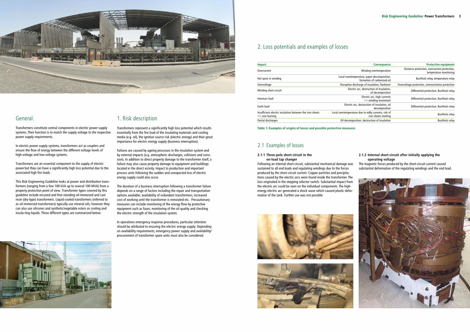
2.1.1 Three-pole short-circuit in the on-load tap changer
Following an internal short-circuit, substantial mechanical damage was sustained to all end leads and regulating windings due to the forces produced by the short-circuit current. Copper particles and precipita-tions caused by the electric arcs were found inside the transformer. The loss originated in the stepping selector switch. Substantial impact from the electric arc could be seen on the individual components. The high-energy electric arc generated a shock wave which caused plastic defor-mation of the tank. Further use was not possible.
2.1.2 Internal short-circuit after initially applying the operating voltage
The magnetic forces produced by the short-circuit current caused substantial deformation of the regulating windings and the end lead.
Table 1: Examples of origins of losses and possible protective measures
Impact Consequence Protective equipment
Overcurrent Winding overtemperatureDistance protection, overcurrent protection,
temperature monitoring
Hot spots in windingLocal overtemperature, paper decomposition,
formation of carbonized oilBuchholz relay, temperature relay
Overvoltage Disruptive discharge of insulation, flashover Overvoltage protection, overexcitation protection
Winding short-circuit Electric arc, destruction of insulation, oil decomposition
Differential protection, Buchholz relay
Interturn faultElectric arc, high currents
=> winding movementDifferential protection, Buchholz relay
Earth faultElectric arc, destruction of insulation, oil
decompositionDifferential protection, Buchholz relay
Insufficient electric insulation between the iron sheets => core burning
Local overtemperature due to eddy currents, risk of iron sheets melting
Buchholz relay
Partial discharges Oil decomposition, destruction of insulation Buchholz relay

5Risk Engineering Guideline: Power Transformers4 Risk Engineering Guideline: Power Transformers
2.1.3 Explosion of a bushingA leaking bushing resulted in the ingress of air and moisture. This weakened the bushing's insulation properties, finally resulting in a flashover inside the bushing causing a fire. This fire could only be extin-guished after all the oil in the compensation tank had been burned.
3. Function principle and basic design
The principle of energy transmission in transformers relies on magnetic flow and induction. The electric alternating current flowing through the primary windings (N1) induces a magnetic flow in the iron core on which the coils of primary and secondary windings are wound. The magnetic flow in the iron core induces a voltage into the secondary winding (N2). The value of the induced voltage depends on the ratio of windings of the coil pairs (primary and secondary windings) (U1/U2 = N1/N2). Changing the number of windings therefore allows changing of the secondary voltage.
Typically, transformers transmitting electric energy offer degrees of efficiency of more than 99%.
Autotransformers represent a special transformer design in electric energy transmission systems. These transformers have no galvanic isolation between the primary and secondary winding.
3.1 Types of construction
Oil-immersed transformers are used extensively to supply and distribu-te electric energy. They range from distribution transformers with ratings of 50 kVA at 10 kV (higher voltage) up to machine and unit transformers with ratings of above 1,000 MVA at up to 1,200 kV.
The range of dry-type transformer ratings is smaller in comparison to oil-immersed because the electric strength is lower and the cooling properties are less favourable. The reason for this is due to material and design properties which are less positive as compared with oil-immersed transformers. Although ratings of up to 50 MVA and voltage levels of up to 52 kV (higher voltage) can currently be realized, they are typically used as distribution transformers with ratings of up to 2,500 kVA.
3.1.1 Oil-immersed transformers
Oil-immersed transformers are transformers which use oil for cooling and electric insulation of the active section. The individual windings of an oil-immersed transformer are insulated by kraft paper wrapped around the individual windings and supplemented by additional paper layers between the wrapping layers. After filling the transformer, the kraft paper is completely impregnated with oil. This is why a liquid-cooled transformer offers a certain degree of self-healing in case of insulation faults because decomposition products are flushed away from the faulty spots.
Decomposition products from insulation faults or overload may be solids or gases. The gas quantity can be detected using a Buchholz
relay installed between the transformer tank and the compensating tank. Depending on the gas quantity produced, a message can be generated or the transformer can be disconnected from the electrical supply (the Buchholz relay acts on the transformer circuit-breakers). Analogue systems are also available for sealed transformers.
Temperature variations cause a change in the volume of oil used. This is caused by changes of ambient temperature and load. The compensa-ting tank typically takes care of compensating this volume change.
Oil-immersed transformers without a compensating tank are referred to as sealed transformers because the oil in these transformers have no contact with the ambient atmosphere. In these transformers, the compensation of oil volume changes caused by temperature variations is achieved by stretching radiators.
Even though sealed transformers are mostly used as distribution trans-formers, they can be used as unit transformers also for example e.g. in combined cycle power plants.
Alternative insulating liquids include vegetable oils, silicones and esters. These liquids differ essentially in their fire protection and biolo-gical properties.
3.1.1 Dry-type transformersBesides the conventional wire windings, the coils frequently consist of films or strips. The essential benefit is that only half of the voltage per layer is required compared with using wire windings. Aluminium is frequently used for the higher-voltage side which reduces the mechani-cal stress when the temperature changes because the thermal coeffici-ent of expansion of aluminium is closer to that of the cast resin as compared to copper.
When selecting dry-type transformers, not only the electric characteris-tics, but also ambient and climatic categories as well as classes of flammability according to DIN EN 60076-11) must be taken into ac-count:
Ambient categoriesWith regard to humidity, condensation and pollution, three different environmental classes are defined:• Class E0: No condensation occurs on the transformers and polluti-
on is negligible. This is commonly achieved in a clean, dry indoorinstallation.
• Class E1: Occasional condensation can occur on the transformer(for example, when the transformer is de-energised). Limited pol-lution is possible.
• Class E2: Frequent condensation or heavy pollution or combinati-on of both.
Table 2: Typical fields of application of transformers
Examples of oil quantities:Distribution transformers: 100 – 1,100 l / 80 – 900 kg Power/unit transformers: up to 150 t
Typical range of ratings
Oil-immersed transformer
Dry-type transformer
Compensation tank
Hermetic sealing
Distribution transformer
50 – 2.500 kVA @ 36kV
X X X
Power transformer
2,5 – 1.200 MVA @ 400kV
X
Machine transformer / unit transformer
10 – 1.200 MVA @ 400kV
X
Climatic categoriesTwo climatic classes are defined:• Class C1: The transformer is suitable for operation at ambient tem-
perature not below –5°C but may be exposed during transport andstorage to ambient temperatures down to –25°C.
• Class C2: The transformer is suitable for operation, transport andstorage at ambient temperatures down to –25°C.
Classes of flammabilityTwo fire behaviour classes are defined:• Class F0: There is no special fire risk to consider. Except for the
characteristics inherent in the design of the transformer, no specialmeasures are taken to limit flammability. Nevertheless, the emissi-on of toxic substances and opaque smoke shall be minimized.
• Class F1: Transformers subject to a fire hazard. Restricted flamma-bility is required. The emission of toxic substances and opaquesmokes shall be minimised.
Figure 1: Sectional view of oil-immersed transformer

7Risk Engineering Guideline: Power Transformers6 Risk Engineering Guideline: Power Transformers
3.3 Cooling types
3.3.1 Oil-immersed transformersOil-immersed transformers are distinguished by their type of cooling. The distinction of oil-immersed transformers is realized by using a four-letter code. According to DIN EN 60076-2, the key to this code is as follows:
Note from DIN EN 60076-2 regarding the type of cooling of oil-im-mersed transformers:
“Note: In a transformer with a forced directed oil flow (2nd letter: D), the oil quantity flowing through the main windings is determined by the pumps and basically not by the load.A small part of the oil quantity flowing through the cooler can be used as a controlled bypass and directed so that the iron core and other
Figure 2: Sectional view of dry-type transformer
3.2 Connections and connection groups
According to EN 60076-1, the connected phase windings of a three-phase transformer (or the windings of identical voltage of single-phase transformers of a three-phase bank) are referred to as Y, D and Z (capi-tal letters) for the higher-voltage side winding and as y, d and z (small letters) for the medium-voltage or lower-voltage side winding. Here Y (y) represents the star connection, D (d) the delta connection and Z (z) the zigzag connection. If the neutral point of windings realized in a star or zigzag configuration is brought out, this is referred to as YN(yn) or ZN (zn).
As per EN 60076-1, the connections are defined as follows:
Star connection (Y connection)This is where the winding connection at one end of each winding phase of a three-phase transformer or of each winding of the same rated voltage of single-phase transformers is connected at one com-mon point (the neutral point) to obtain a three-phase bank. The other end is connected with the corresponding conductor terminal.
Delta connection (D connection)This is where the winding connection in which the winding phases of a three-phase transformer or the windings of the same rated voltage of single-phase transformers are connected in series and form a closed circuit to obtain a three-phase bank.
Table 3: Marking of cooling type of oil-immersed transformers
Tab. 4: Description of cooling type
elements not being part of the main winding are cooled. Stepped windings and/or other windings of relatively low power can also be cooled by undirected bypass oil.
In a transformer with undirected forced cooling (2nd letter: F), the oil flow rate through all windings depends on the load and has no direct connection with the oil quantity pumped through the cooler”.
The designation of the type of cooling also applies to alternative insu-lating liquids, e.g. esters.
3.3.2 Dry-type transformersDry-type transformers are marked in accordance with the applied type of cooling. These transformers use a two-letter code for marking. According to DIN - EN 60076-11, the key to this code is as follows:• 1st letter: Cooling agent (A=Air)• 2nd letter: Cooling agent movement (N=Natural; F=Forced)
Definitions according to ANSI/IEEE C57.12.01 include:
3.4 On-load tap changers and off-load tap changersClass AA: natural ventilationClass AFA: forced ventilationClass AA/FA: natural/forced ventilationClass ANV: no ventilation, self-coolingClass GA: sealed, self-cooling
Transformers may be equipped with on-load or off-load tap changers. These units enable the transformation ratio to be adjusted within certain limits. To achieve this, different winding taps are connected to switches or off-load tap changers. These are used for switching single or several windings on or off. Depending on the design, the on-load and off-load tap changers are located inside the transformer tank or are installed on the outside.
An on-load tap changer allows setting of the voltage under load. As a general rule, a distinction is made between liquid-insulated switches and vacuum switches. The insulating liquids used are the same as in transformers, i.e. mineral oils, esters and silicone oils. Electric arcs cannot be avoided when performing switching operations under load and cause oil pollution. This is why on-load tap changers have their own tanks and consequently are separated from the transformer oil. Usually, these are equipped with a separate compensating tank (inclu-ding protective relay) and an automatic oil filter unit.
1st letter:Internal coolant in contact with the windings
2nd letter:Type of internal coolant circuit
3rd letter: External coolant
4th letter:Type of external
coolant circuit
O (Oil)Mineral oil or syntheticinsulating liquid with afire point ≤300 °C*)
N (Natural)Natural thermosiphon flow
through radiator and windings
A (Air)Air
N (Natural) Natural convection
KInsulating liquid with afire point >300 °C*)
F (Forced)Forced circulation through theradiators, thermosiphon flow
through the windings
W (Water) Water
F (Forced)Forced circulation
(fans, pumps)
LInsulating liquid of unmeasurable fire point
D (Directed)Forced circulation through the
radiators, directed at least into the main windings by the radiator.
*) „Cleveland Open Cup” test method, see ISO 2592 Petroleum Products – Determination of flash and fire points – Cleveland open cup method
Designation Description
ONANOil-immersed transformer with natural convection,
no additional units (e.g. fans) are required for cooling the transformer.
ONAFOil-immersed transformer the outer oil cooler of which
is ventilated by fans.
OFAFOil-immersed transformer with an insulating
oil recirculation pump and fans ventilating the outer oil coolers.
OFWFOil-immersed transformer with an insulating
oil recirculation pump and a water cooler with a pump for recirculating the cooling water.

9Risk Engineering Guideline: Power Transformers8 Risk Engineering Guideline: Power Transformers
In contrast off-load tap changers adapt the voltage while the transfor-mer is shut down without exception. Consequently, electric arcs will not occur. Separation from the transformer oil is therefore not required.
In vacuum-insulated on-load tap changers, there is no direct contact of active parts with the insulating liquids. Switching occurs in evacuated chambers. Pollution of insulating liquid by electric arcs is therefore excluded. This results in clearly reduced maintenance efforts as compa-red with liquid-insulated on-load tap changers.
4. Insulating systems Although the design and cooling of liquid-cooled transformers and dry-type transformers may differ considerably, the (primary) insulation of the individual windings and coil layers is solid in both systems. In dry-type transformers, typically films, enamel and aramide are used, depending on the way the windings are executed. In liquid-cooled transformers cellulose paper (kraft paper or thermally upgraded paper) is typically used. Insulation of the individual coils is by the liquid or the cast resin.
4.1 Oil-immersed transformer
The decomposition products produced during operation of an oil-immersed transformer depend essentially on the operating mode and the load which can affect the oil quality. The electric strength of the oil is mainly determined by its water content.
The increase in moisture cannot always be avoided due to operating conditions. Typical reasons include the ingress of air through the oil compensating tank and the chemical decomposition of cellulose. The latter is the reason why oil analysis of sealed transformers is also necessary at regular intervals. Two different paper grades are mainly used for insulating liquid-cooled transformers. Kraft paper is mainly found in older transformers (built before 1980). Thermally upgraded paper has been used since 1970.
The main difference between the two paper grades is their thermal stability. Thermally upgraded paper allows higher operating temperatu-res than kraft paper. Moreover, these paper grades differ in producing different gases during operation as well as different amounts of furfu-ral (organic compound).Assessing the oil condition therefore requires specific oil analysis to be completed.
The average degree of polymerisation (DP) is one result of this condi-tion analysis. The DP provides information about the mechanical pro-perties of the insulating paper. The more cellulose decomposed due to paper ageing results in a lower DP and mechanical stability. New insulating paper has typical DP values of between 1,100 and 1,300, the DP value of dried paper is around 950. Depending on the DP values, cellulose decomposition must be interpreted as follows:
• DP 900-700 ≙ little decomposition• DP 700-500 ≙ medium decomposition• DP 500-200 ≙ strong decomposition• DP <200 ≙ total decomposition
Ageing of the insulation system also depends on the operating tempe-rature. The connection between temperature and ageing is described by the Arrhenius graph. This graph indicates a service life reduction of the insulation system by 50% per 6 Kelvin above the specific operating temperature.
4.2 Ester transformer
In contrast to mineral oils, ester liquids are thermally more stable. Ester transformers can therefore be designed smaller/more compact in comparison to oil-immersed transformers and can also be operated at higher output level.
Biological esters oxidise very quickly upon contact with oxygen, hence the reason why they are used predominately in sealed transformers. Typical locations where they are used include natural reserves and water protection areas. Ester transformers are also usually installed on railway motor coaches.
Substituting oil by ester is normally possible, however requires the suitability and compatibility of transformer components being checked and explicitly approved by the transformer manufacturer.
4.3 Cast resin transformer
The primary insulation used between the individual film winding layers is film. Primary insulations of wire windings are usually made of ena-mel. Aramide tissue or paper can be used as an option also. As the coils are embedded in solids, regeneration of insulation faults is exclu-ded. Defects inside the coils therefore require replacing of the coils.
Table 5: Ageing and expected service life (rounded) as a function of temperature
Table 6: Properties of insulating liquids
5. Machinery protection
An undetected fault could result in substantial damage and destruction of the transformer beyond repair, causing a long-term business inter-ruption.
Machinery protection serves for detecting transformer operating condi-tions to ensure they are in line with the intended use. The scope of protective equipment installed should be governed by the value and availability requirements of the transformer.
The transformer is automatically separated from the power system as soon as active protective equipment responds. This prevents further damage to the transformer. Consequential losses may occur in specific cases due to this de-energizing of the supplied equipment. Operations can usually be resumed after evaluating and where applicable remo-ving the reason for the shut-down.
To prevent sudden and unexpected de-energizing, providing a pre-alarm is a common feature of Buchholz relays and temperature moni-toring units. Pre-alarms should be used for starting preventive action for troubleshooting. If failure of a transformer cannot be compensated by other transformers, stand-by generating sets may represent a useful alternative, especially when sensitive equipment could be damaged by the power being switched off; and when unsafe operating conditions or a long-term business interruption may be anticipated.
5.1 Active protective equipment
Active protective equipment includes systems which react to physical or chemical changes by using sensors and actuators. Usually failure to comply with threshold values can result in the transformer being shut down. In this process, the protective equipment controls the transfor-mer circuit breakers.
Temperature monitoringThe transformer oil temperature is continuously monitored. When the temperature rises above a pre-set value, an alarm is generated. The energy flow through the transformer should be reduced as a qualified reaction or the transformer should be shut down altogether. Operation at elevated temperatures will accelerate the ageing processes inside the transformer. Consequences may include damage to the active transformer section (e.g. disruptive discharge of dielectric due to swit-ching overvoltage).
Buchholz relayThe Buchholz relay is a protective feature for oil-cooled transformers with a compensating tank. It is provided between the transformer tank and the compensating tank and detects faults inside the transformer. Insulation faults or overload result in gas formation.
Low-energy partial discharges and local overheating can cause slow decomposition processes to occur and formation of small amounts of gas. This gas is collected in a chamber of the Buchholz relay and, upon reaching a certain level, makes a float switch respond (pre-alarm).
High-energy disturbances such as electric arcs produce large amounts of gas. The shock wave travelling towards the compensating tank actuates a baffle plate (main alarm). The main alarm must isolate the transformer.
Temperature [°C] Kraft paper Thermally upgraded paper
Rate of ageing Expected service life Rate of ageing Expected service life
98 1 30 years - -
104 2 15 years - -
110 4 8 years 1 30 years
116 8 4 years 2 16 years
122 16 2 years 3 9 years
128 32 1 years 6 5 years
Property Unit Mineral oil Silicone liquid Synthetic esters Biologic esters
Viscosity (20°C) mm²/s 20 50 70 85
Viscosity (100°C) mm²/s 3 15 5 8

11Risk Engineering Guideline: Power Transformers10 Risk Engineering Guideline: Power Transformers
Pre-alarm Main alarm
Figure 4: Buchholz relay layout
Differential protectionDifferential protection monitors the total of incoming and outgoing currents. When considering the transformation ratio and the rush effect, the total of currents in a flawless system equals zero.
Distance protectionDistance protection is a power system protection unit which perma-nently calculates the current impedance (resistance) of the line by measuring the voltage and the current in all three phases. In case of fault (e.g. earth fault or conductor fault), the current intensity in the phase concerned increases and at the same time, the voltage drops (this equals a reduction of loop impedance). When the impedance drops below a certain value, protection is activated and cuts off the respective supply system section.
Definite-time maximum current protection (UMZ relay)The UMZ relay is excited when a pre-set absolute current value is exceeded; however, this relay is triggered only after a time delay in order to disregard very short-time excess values. This delay is a pre-set value and independent of the absolute current value.
To improve the selectivity of this protection type, several UMZ relays are connected in series. In this configuration, the shortest delay is pre-set for the protection zone with the greatest distance from the feeder point.
Inverse-time maximum current protection (AMZ relay)As with the UMZ relay, the AMZ relay involves measuring the absolute current value. The tripping time is inversely proportional with the measured short-circuit current. This cuts off larger fault currents more quickly than smaller fault currents.
Due to its selective tripping time, the AMZ relay reacts directly to the actually applied short-circuit capacity. The calculations required for AMZ relays are quite complex and as such tend not to be used in energy supply systems; however they are, used for components such as generators and transformers.
5.2 Passive protective equipment
Passive protective equipment includes systems which will not control switching equipment for tripping and/or for fulfilling their protective function. There is no ACTUAL/TARGET value comparison of physical/technical parameters.
Lightning protectionTo maintain atmospheric discharges to a minimum, transformers and overhead lines connected to them must be protected by lightning rods and lightning ropes installed above the equipment and overhead line towers.
The lightning rods, the overhead line towers and the transformer tank must be earthed.
Overvoltage protectionOvervoltage protection serves for protection against transient overvol-tage from the supply system or the environment. The values of volta-ges caused by switching operations or atmospheric discharge, e.g. lightning, can be limited by providing surge arresters. Surge arresters must be installed on the active transformer conductors and on the interfaces with the switchgear.
ReactorsReactors serve for limiting the overvoltage when shedding off load and short-circuit and earth fault current.
DehumidifiersThe compensation tank of a transformer has an opening allowing air to flow in and out in order to compensate volume changes of the transformer oil due to temperature changes.
Dehumidifiers absorb the air humidity flowing into the compensation tank. This avoids a decrease of the insulating agent’s electric strength and the formation of condensate in the compensation tank, (both typically caused by humid ambient air).
When the silica gel is saturated with moisture, its colour changes from BLUE to PINK or from ORANGE to WHITE.
6. Fire protection
Depending on design, insulation system, values and availability requi-rements, different fire protection requirements may apply. The measu-res to be considered can be sub-divided into structural, technical and organizational measures.
Mineral oils have a flash point of approx. 150 °C whereas; silicone liquids and synthetic ester tend to be around 260 °C with natural esters reaching more than 300 °C. The fire points of mineral oil are around 170 °C whereas, synthetic ester is above 300 °C and silicone liquids and natural ester are above 350 °C. Most ester liquids are rated as biodegradable and not hazardous for water.
6.1 Structural fire protection
Transformers must be structurally separated in order to prevent fire spread to neighbouring facilities and equipment.
6.1.1 Outdoor transformers• When installing outdoor transformers a clearance of 25m min. from
buildings, warehouses and other transformers or other operational equipment should be maintained.
• This clearance may be reduced if the outer wall of the building is classed as a fire wall according to NFPA and all adjoining openings are either at least 120 minute fire-resistant or suitable walls towards adjoining areas are provided.
• Separating walls in-between transformers must extend beyond the transformer dimensions (including the compensation tank) by at least 1 m both vertically and horizontally.
• Separate containment bunds must be installed beneath each transformer in order to collect any escaping oil. These trays must be made from non-combustible materials, preferably reinforced concrete. The collecting tray must be filled with broken stone in order to minimize the effects of underfiring (heating from below) caused by escaping burning oil. The dimensions should be such that the entire transformer oil volume can be retained (stored) and the broken stone filling is still above the oil level. As an alternative to broken stone fillings, flame-retarding covers (fire protection grating) may be used.
• When using central underground tanks for collecting the oil, flame arresters must be installed in the lines between the tank and each transformer.
• Adequate dewatering of the collecting tray must be ensured.• The broken stone filling and openings of the fire protection gra-
tings should be kept free from leaves, debris etc.; regular inspec-tion and cleaning should be implemented.
Table 7: Typical fire characteristics of various insulating liquids
Property Unit Mineral oil Silicone liquid Synthetic esters Biologic esters
Flash point °C 150 260 260 316
Fire point (DIN EN 61100) °C 170 >350 >310 >350
Class of inflammability(DIN EN 61039)
O1 K3 K3 K2

13Risk Engineering Guideline: Power Transformers12 Risk Engineering Guideline: Power Transformers
6.1.2 Indoor transformers• Transformers installed inside buildings must be separated with a
fire rating of at least 120 min towards adjoining areas of use inclu-ding electric switchgear and other transformers.
• Floor, wall and ceiling breakthroughs, especially those of ventilati-on systems must either be provided with fire stoppings or be pro-tected by fire-resistant fire protection dampers to be activated au-tomatically in case of fire (at least 120 minutes fire rated). The sa-me applies to gates and doors leading into the building.
• Transformer units should preferably be installed on the groundfloor and in rooms with an outer wall. These rooms should beequipped with an access door opening to the outside. Accessdoors in outer walls usually do not have to meet any particular fireprotection requirements regarding their fire rating.
• Technical rooms for transformers must be sufficiently ventilated.Ventilation openings must be protected against access from ro-dents and small animals.
• Oil transformers must be set up individually in or above collectingtrays made of non-combustible material, preferably reinforcedconcrete.
• Containment bunds must be dimensioned at least so that theentire transformer oil volume can be collected.
6.2 Fixed fire protection
6.2.1 Fire detectionTransformer rooms and cells should be monitored by an automatic fire detection system including automatic fire detectors and alarm trans-mission to a permanently manned station. In an ideal configuration, this station is the central control station of the public fire service/works fire brigade.
Important criteria for selecting a suitable fire detection system include:
Extent of monitoring:• One or several rooms or cells• Cable pits and ducts
Ambient conditions:• Temperature• Air humidity• Ventilation equipment (flow rates)• Dust, fog, birds etc.
Alarms and actions in case of fire• Notify fire brigade• De-energizing transformer• Closing of fire protection dampers• Shut-down of ventilation system
Point-type smoke detectors or smoke aspiration systems can be used for fire detection. A smoke aspiration system continuously withdraws air samples from the area to be monitored through a piping system. The withdrawal points can be located directly next to the suspected place of origin of a fire. These detectors respond very sensitively and are capable of detecting even pyrolysis products which are generated before open flames appear. These systems can be designed so that the susceptibility for false alarms is extremely low by defining suitab-le alarm thresholds based on the occupancy and also offer the benefit of not absolutely having to access the monitored room for mainte-nance.
The design of fire alarm systems should follow internationally recog-nized rules and regulations such as NFPA 72, National Fire Alarm and Signalling Code or other similar recognised standard. It is important that approved systems and components be used when installing any system and all plans be sent to HDI for review prior to installation and commissioning.
6.2.2 Fire protection systemsFire protection systems for transformers may be necessary, depending on the environment and their availability requirements. The primary protection goal here is to clearly reduce the thermal effects on the en-vironment (transformers, switchgear, buildings etc.) in case of a trans-former fire.
Upon activation of the fire protection system, the transformer must be de-energised.
Transformers located inside buildings typically have sprinkler protec-tion or gas extinguishing systems installed whereas, water deluge systems are typically used for outdoor transformers.
The design of the fire protection system should follow internationally recognized rules and regulations such as NFPA 15 – Standard for Water Spray Fixed Systems for Fire Protection Section 7.4.4. It is important that approved systems and components be used when installing any system and all plans be sent to HDI for review prior to installation and commissioning.
6.3 Organizational fire protection
Unauthorized persons must not have access to transformers. Access should be strictly monitored and controlled by providing adequate physical security measures. Access areas must be kept clear of stored goods at all times.
Figure 5: Outdoor transformers
De-energizing transformers should be possible at all times. To enable effective de-energizing the de-energizing point must be located in a safe environment which can be easily accessed. In view of the high availability requirements of the electric energy supply, a supply sys-tem in accordance with the n-1 principle must be aimed at for essen-tial operating areas. This allows compensating failures of single trans-formers.
The emergency response plan should describe the consequences of a transformer failure and accordingly state the remedial measures to re-duce the impact.
It has been proven very valuable to organise annual fire brigade fami-liarization visits and transformer fire scenario training with the local public fire services.
7. Environmental protectionThe necessity of providing collecting spaces is based on on local legislations. The purpose of collecting spaces is to collect substances escaping from the equipment and/or the storage container (including fire water in case of fire) in order to prevent them being leaked into the soil or surrounding waters. The necessary collecting volume must equal the volume of a transformer oil filling volume as a minimum requirement. When setting up several transformers in one collecting space, it must be possible to collect an additional 10% of the total transformer oil filling volume. In systems set up in water protection areas, it must be possible to retain 100% of the total oil filling volume of all transformers.
8. MaintenanceThe ageing of the paper and oil, depends not only on the natural ageing process, but also on the operating conditions. Typically when using a transformer within the rated parameters specified by the ma-nufacturer (normal operating conditions), a typical service life of 30 years and maybe more can be achieved.
Events which cannot be anticipated such as transient overvoltage, dy-namic alternating stress (frequent load changes for which the trans-former was not designed) or thermal overload (e.g. due to a faulty cooling system or deliberate/unconscious permanent overload), may contribute to premature ageing to a considerable extent. In view of these operating modes which are contrary to the intended use of the transformer, failures within the planned service life must be assumed to be probable and a reduced service life must be anticipated.
Parameters influencing the ageing process of organic matter in the transformer include air (oxygen), moisture, temperature as well as electric loads. Ageing under process conditions generates acids, mois-ture and sludge.
Most transformers used today by energy supply companies, grid ope-rators and the industry are typically more than 30 years old. This me-ans that these transformers will reach the end of their typical service life soon (or may have even already exceeded this limit). Age-related failures can therefore be anticipated in these industries.
Transformers must be maintained (at least) in accordance with the manufacturer’s specifications. Particular features of the on-load tap changer must be observed. In addition, general visual inspections and regular cleaning must be carried out.
Additional measuring methods intended for assessing the transformer condition during operation include:• thermographic inspections, especially of connections and leadt-
hroughs,• passive detection of emitted ultrasound waves (Airborne Ultraso-
nic Testing).
8.1 Oil-immersed transformer
The following maintenance work must be carried out on oil-immersed transformers at maximum intervals (can be shorted depending on the last results, i.e. poor DGA retesting done after 6 months, see also re-commendations in IEEE C57-104):
Monthly• Check/replace silica gel in dehumidifier• Check of indicators
Annually• Function test of monitoring equipment• Check for tightness and corrosion (tank, tap changer, protective
relay, leadthroughs)• Cleaning of air intake grilles• Taking oil samples
Every 5 years• Measuring the partial discharge• Revision of monitoring equipment• Revision of fans and pumps• Revision of on-load tap changer (mechanical components and con-
tacts)
Advanced monitoring systems are automated monitoring systems. These systems continuously monitor transformer operating parame-ters and can even perform automatic online oil analyses to a limited extent. When installing such monitoring systems, the intervals of indi-vidual inspections may also be adapted.
Decomposition products can never be excluded during operation of a liquid-cooled transformer. Analysis of the transformer oil at regular intervals allows better condition monitoring of the transformer's insu-

15Risk Engineering Guideline: Power Transformers14 Risk Engineering Guideline: Power Transformers
Table 8: Oil analysis diagnosis methods
lation system. Depending on the load and age of the transformer, on the results of previous analyses and on availability requirements, the date of the next inspection must be fixed. The intervals between oil analyses should not exceed three years.
8.2 Transformer oil
Table 8 gives a summary of diagnosis methods. Further information about these methods can be found in the standards mentioned below. This list is not exhaustive.
8.3 Bushings
• IR annually• 4 yearly power factor test
Diagnosis/standards Explanation
Gas-in-oil analysis (Dissolved Gas Analysis – DGA)Standards: DIN EN 60475,DIN EN 60599,Din EN 60567
Analysis of cracking gases dissolved in the oil.
The quantity and the type of fault gases, the gas rise rates and the ratio of the gases with respect to one another allows drawing conclusions about the type of fault.
Most faults detected are developing slowly. Trend analyses enable forecasts regarding the service life of the transformer. Examples:
• Identification of hot spots• Partial discharges/discharges• Building-up of impurity films on contacts• Local overheating of metal parts• Saturation of transformer with air (possible consequence: tripping of Buchholz relay without a fault on the transformer)
Degree of depolymerisation (DP) / furan analysis Standards:DIN EN 60450
The DP value is a parameter of the degree of paper insulation decomposition. Lowering of the DP value indicates ageing of the paper insulation (reduction of mechanical strength of paper insulation).
Taking paper/cellulose samples during operation (insulation of windings) is not possible. Some cellulose decomposition products (furans) are soluble in oil. Determining the furan portion allows drawing conclusions about the condition of the paper insulation.
Note: As furans are decomposed in different ways in thermally upgraded paper and in kraft paper, knowledge of the paper used is indispensable.
Oil characteristicsStandards:DIN EN 30296,DIN EN 60422
• Colour and appearanceStandard: DIN ISO 2049
Colour and appearance (clear, cloudy, with sediments) represent no sole assessment criteria for a qualitative assessment of the transformer. These are indicators of the ageing process (comparative assessment).
• Dielectric strenght Norm: VDE 0370-5
Describes the dielectric strength of the oil and is an important Standard: indicator of the operational reliability of the transformer.
• Moisture contentNorm: VDE 0370-5
Influences the electric strength of the insulation system and Standard: VDE accelerates the ageing process of the oil.
• Neutralization number(Acid content)
The ageing process (oxidation) generates acid components in the oil. These reduce the insulation resistance of the solid insulation.
• Dielectric strengthThe loss factor is influenced by the presence of polar components.Polar components include e.g. water and ageing products resulting from oil and paper/cellulose.
• Sludge formation This is an indicator of sludge formation in the transformer.
• Inhibitor content Inhibitors delay the decomposition of the insulating oil.
9. References
Local standards should be complied with
ANSI/IEEE C57.12.00 General Requirements for Liquid-Immersed Distribution, Power, and Regulating Transfor-mers
ANSI/IEEE C57.12.01 General Requirements for Dry-Type Distribu-tion and Power Transformers
ANSI/IEEE C57-104 Guide for the Interpretation of Gases Gene-rated in Oil-Immersed Transformers
ASTM D3612 Standard Test Method for Analysis of Gases Dissolved in Electrical Insulating Oil by Gas Chromatography
DIN EN 13501 Fire classification of construction products and building elements - Part 1: Classification using data from reaction to fire tests
DIN EN 60666 Detection and determination of specified additives in mineral insulating oils
IEC 60076-1 Power Transformers - General
IEC 60076-2 Power transformers - Part 2: Temperature rise for liquid-immersed transformers
IEC 60076-11 Power transformers - Part 11: Dry-type transformers
IEC 60156 Insulating liquids - Determination of the breakdown voltage at power frequency
IEC 60296 Fluids for electrotechnical applications
IEC 60422 Mineral insulating oils in electrical equipment
IEC 60450 Measurement of the average viscometric degree of polymerization of new and aged cellulosic electrically insulating materials
IEC 60475 Method of sampling insulating liquids
IEC 60567 Oil-filled electrical equipment - Sampling of gases and analysis of free and dissolved gases
IEC 60599 Mineral oil-filled electrical equipment in service
IEC 61039 Classification of insulating liquids
IEC 60666 Detection and determination of specified addi-tives in mineral insulating oils
IEC 61100 Classification of insulating liquids according to fire-point and net calorific value??
ISO 2049 Petroleum products - Determination of colour (ASTM scale)
NFPA 15 Standard for Water Spray Fixed Systems for Fire Protection
NFPA 25 Standard for the Inspection, Testing and Main- tenance of Water-Based Fire Protection Systems
NFPA 72 National Fire Alarm and Signaling Code

16 Risk Engineering Guideline: Power Transformers
Although we made every effort possible to ensure the accuracy of the information provided, no liability can be assumed for the currentness, correctness and completeness of the information. We neither intend, nor assume any obligation, to update or revise these statements in light of developments which differ from those anticipated.
Benefits of HDI Risk Consulting
> Comprehensive Risk Engineering expertise in the identification, as-sessment and mitigation of operational risks.
> Qualified international Risk Engineering network offers clients worldwide multi-discipline support in Risk Engineering.
> HDI Risk Consulting is a wholly owned subsidiary of HDI Global SE and thus part of the Talanx Group, one of the largest insu- rance groups in Germany and Europe.
Contact
For questions and/or more information you can contact us via:
HDI Risk Consulting GmbHHDI-Platz 1D-30659 Hannover+49 511 645-3219 www.hdi.global
Imprint Responsible for the content:HDI Risk Consulting GmbH
Layout: Insignio Kommunikation GmbHImages: HDI Risk Consulting GmbH, Siemens AG
About HDI Risk Consulting … • HDI Risk Consulting GmbH supports major corpo-
rations, industrial and mid-size companies with loss prevention and in establishing risk manage-ment systems.
• HDI Risk Consulting offers its’ customers access to some 170 engineers and experts from a wide range of technical disciplines. We aim to support companies with the management of risks and the development of individual risk-based concepts for insurance cover.
• HDI Risk Consulting operates globally in the Property, Motor, Engineering and Marine markets, with particular focus on the identification and assessment of risks and the development of appro-priate, individual protection concepts.
• HDI Risk Consulting GmbH is a wholly owned subsidiary of HDI Global SE.
403-
HRC
/REG
123G
B 20
2011