CNWRA 94-010, "Review of Degradation Modes of Alternate ...
117
Prepared for Nuclear Regulatory Commission Contract NRC-02-93-005 Prepared by Center for Nuclear Waste Regulatory Analyses San Antonio, Texas April 1994
-
Upload
khangminh22 -
Category
Documents
-
view
0 -
download
0
Transcript of CNWRA 94-010, "Review of Degradation Modes of Alternate ...

Prepared for
Nuclear Regulatory CommissionContract NRC-02-93-005
Prepared by
Center for Nuclear Waste Regulatory AnalysesSan Antonio, Texas
April 1994

CNWRA 94-010
REVIEW OF DEGRADATION MODES OF ALTERNATECONTAINER DESIGNS AND MATERIALS
Prepared for
Nuclear Regulatory CommissionContract NRC-02-93-005
Prepared by
Narasi Sridhar, Gustavo A. CragnolinoDarrell S. Dunn, and Hersh K. Manaktala
Center for Nuclear Waste Regulatory AnalysesSan Antonio, Texas
April 1994

PREVIOUS REPORTS IN SERIES
Number Name Date Issued
CNWRA 91-004
CNWRA 91-008
A Review of Localized Corrosion of High-LevelNuclear Waste Container Materials-I
Hydrogen Absorption and Embrittlementof Candidate Container Materials
April 1991
June 1991
CNWRA 92-021 A Review of Stress Corrosion Cracking ofHigh-Level Nuclear Waste Container Material-I
August 1992
CNWRA 93-003 Long-Term Thermal Stability of High-Level February 1993Nuclear Waste Container Materials-IThermal Stability of Alloy 825
CNWRA 93-004 Experimental Investigations of LocalizedCorrosion of High-Level Waste Container Materials
February 1993
CNWRA 93-014 A Review of the Potential for MicrobiallyInfluenced Corrosion of High-Level Nuclear Waste Containers
June 1993
ii

ABSTRACT
Issues related to the performance of alternate container materials, including materials currently beingconsidered for multipurpose canisters (MPCs), are reviewed in this report. The MPC is being consideredto be a completely sealed canister containing spent fuel bundles that can be transferred within overpacksfrom the plants through intermediate storage sites to the eventual disposal site. Hence, the structuralintegrity of the MPC is important. The mechanical integrity of the MPC materials, especially in thewelds, can be impaired due to embrittlement under long-term exposure to temperatures of 200-300 'Cdue to the precipitation of a ' and a phases. Currently, there are insufficient data to quantitatively predictthe extent of the embrittlement. The issues related to the performance of disposal overpacks varydepending upon the class of materials. Carbon steel overpacks can suffer from embrittlement due to grainboundary segregation of phosphorus. Type 316L stainless steel (SS) and alloy 825 overpacks can beembrittled due to a and Laves phase precipitation. These embrittlement kinetics can be accelerated bylocal plastic deformation or by welding-induced segregation. The near-field environment in the proposedrepository at Yucca Mountain is uncertain, but may involve a wide range of chloride concentrationthrough evaporative concentration of aqueous environment contacting the container. In aqueousenvironments and under mildly alkaline conditions, carbon steel can suffer from localized corrosion andstress corrosion cracking (SCC). Hydrogen generated from corrosion can cause embrittlement of carbonsteel or cast iron due to either dissolved hydrogen directly or hydrogen reacting with carbides to formmethane. Microbial action can be increased by the presence of carbon steel and may promote eitherlocalized corrosion or increased generation of hydrogen. The galvanic coupling between carbon steel anda corrosion resistant alloy, such as type 316L SS, can be beneficial in terms of the localized corrosionresistance of the latter. However, hydrogen embrittlement of the corrosion resistant alloy, especially thehigh-nickel alloys such as alloy C-4, is a possibility due to cathodic polarization. Specific areas that needfurther investigation are enumerated.
iii

CONTENTS
Section Page
ABSTRACT ...............................FIGURES .................................TABLES .................................ACKNOWLEDGMENTS.EXECUTIVE SUMMARY ......................
iiiviixx
xi
. . . . . . . . . .. . . . . . . . . .. . . . . . . . . .
1 INTRODUCTION .1.1 ALTERNATE CONCEPTUAL DESIGNS & MATERIALS.1.2 ENVIRONMENTAL CONSIDERATIONS.
2 CARBON STEEL AND CAST IRON MATERIALS .2.1 THERMAL STABILITY.2.1.1 Wrought Steels.2.1.2 Ductile Iron.2.1.3 Section Size.2.2 CORROSION .2.2.1 Effect of Environmental Factors on Uniform Versus Localized Corrosion2.2.2 Atmospheric Corrosion Studies.2.2.3 Corrosion in Seawater .2.2.4 Corrosion in Repository Environments.2.2.4.1 Uniform Corrosion Studies .............................2.2.4.2 Localized Corrosion .................................2.3 STRESS CORROSION CRACKING AND HYDROGEN-ASSISTED CRd2.3.1 Stress Corrosion Cracking ..............................2.3.2 Hydrogen-Assisted Cracking Phenomena .....................2.3.2.1 Terminology ......................................2.3.2.2 Hydrogen Embrittlement ...............................
.........
1-1
..........
1-1
. . . .8.. . . 1
2-12-12-12-62-9
2-102-112-162-172-192-202-232-282-282-382-382-392-412-45
. . . . ..
. . . . ..
kCKING. .. . .
. .. . .
2.3.2.3 Hydrogen Attack ...................2.4 MICROBIALLY INFLUENCED CORROSION
. . . . . . . .
3 STAINLESS STEELS AND NICKEL-BASED ALLOYS . .3.13.1.13.1.1.13.1.1.23.1.23.1.2.13.1.2.23.23.2.13.2.2
THERMAL STABILITY .............................Thermal Stability of Multipurpose Canister Materials ............Wrought Materials .................................Weld Metal ......................................Thermal Stability of Disposal Overpack (Container) Materials.Wrought Materials .................................Weldment .......................................ENVIRONMENTAL EFFECTS .........................Localized Corrosion ................................Stress Corrosion Cracking .............................
.... 3-1
.... 3-1
. . . .3-1. . . .3-1. . . .3-2.... 3-7.... 3-7.... 3-8.. . 3-10... 3-10.. . 3-16... 3-193.2.3 Hydrogen Embrittlement/Damage .. .
iv

CONTENTS (cont'd)
Section Page
4 SUMMARY AND RECOMMENDATIONS ........................... 4-14.1 SUMMARY ..... ............................... 4-14.1.1 Carbon Steels and Cast Irons ...................... 4-14.1.2 Type 316L Stainless Steel .................... 4-44.1.3 Alloy 825 .................... 4-54.1.4 Alloy C-4 and Related Alloys .................... 4-64.2 RECOMMENDATIONS .................... 4-6
5 REFERENCES .................... 5-1
v

FIGURES
Figure Page
1-1 Schematic diagram of a proposed design for a robust waste package as a standalonecontainer or a disposal overpack for a large MPC containing 21 PWR assemblies(U.S. Department of Energy, 1993b) ................................ 1-3
1-2 Schematic drawing of the currently proposed large MPC that can contain 21 PWR
assemblies (U.S. Department of Energy, 1993b) .......... ............... 14
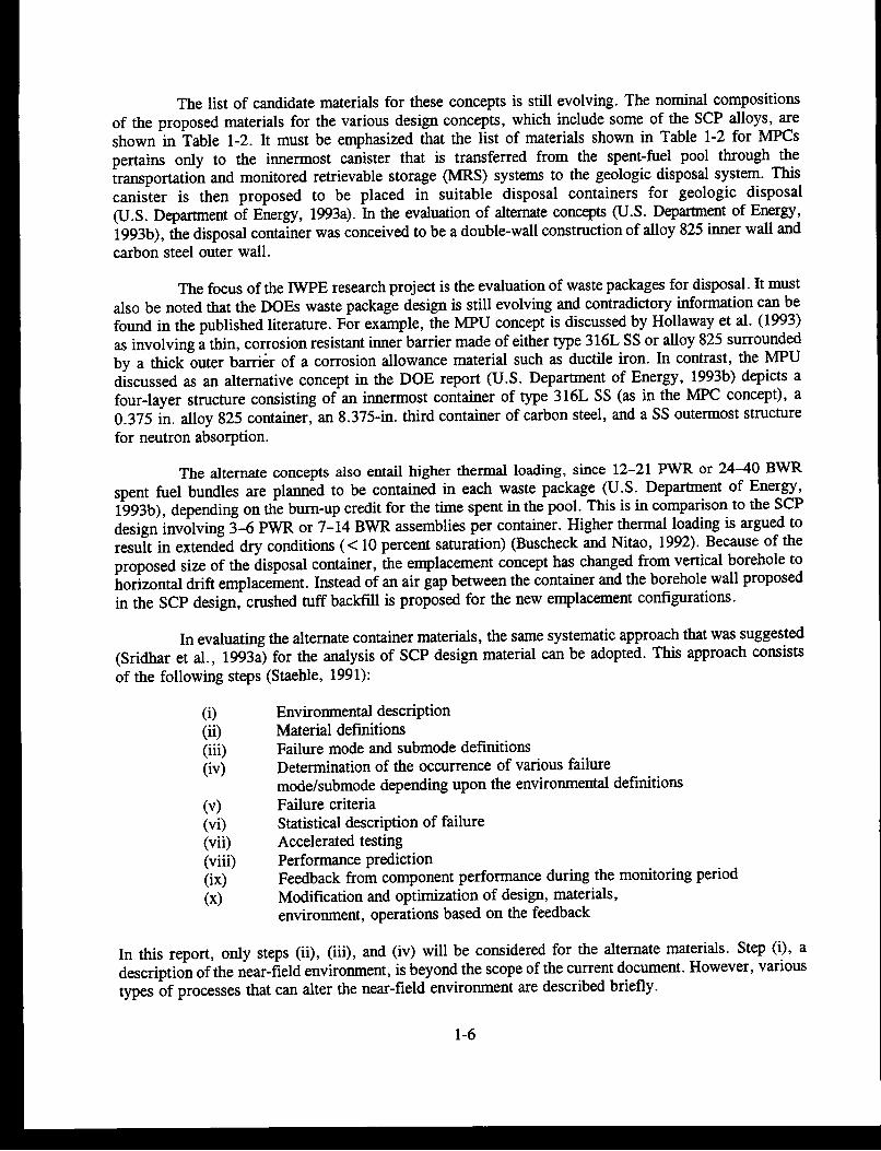
1-3 Schematic drawing of the currently proposed large MPU that can contain 16 PWR
assemblies (U.S. Department of Energy, 1993b) .......... ............... 1-5
2-1 Distribution of various elements in iron. Some of the industrially important alloyingelements and impurities are indicated by shaded areas ...... ............... 2-2
2-2 Dependence of DBTT at 80 Joules as a function of grain boundary P. A model alloywith nominal composition of A533-B was aged at temperatures 375 to 600 0C
(Vatter et al., 1993) .2-62-3 Effect of graphite shape on the mechanical properties of cast irons .2-1024 Effect of temperature on the corrosion rate of iron in water containing dissolved
oxygen in open and closed systems (Speller, 1951) ...................... 2-13
2-5 Corrosion rate of iron as a function of sodium chloride concentration at ambienttemperature (Uhlig and Revie, 1985). IPY = Inch per year ................. 2-14
2-6 Oxide film thickness on low carbon steel as a function of time at 100, 150, 200, and
250 'C (Szklarska-Smialowska and Jurek, 1976) ........................ 2-18
2-7 Parabolic growth of oxide film thickness for low carbon steel at 250, 300, and 350 'C(Szklarska-Smialowska and Jurek, 1976) ............................. 2-19
2-8 Potential pH diagrams determined by cyclic polarization of carbon steel at 50 0C(Marsh et al., 1985) ......................................... 2-24
2-9 Schematic diagram of current flow for reactive and nonreactive pit walls (Beaverset al., 1987a) ............................................... 2-27
2-10 Current density distribution with time for iron undergoing pitting corrosion in a 1 mM
NaCI + 1 mM Na2 SO4 solution (Isaacs, 1987) ......................... 2-29
2-11 Pit number density and pit depth on low carbon steel at 100 0C in 0.006 N NaCl +
0.009 M Na2SO 4. Open symbols represent solution deaerated with Ar/5 %H2. Filled
symbols for solutions deaerated with argon containing 200 ppm 02 as an impurity
(Bhakta and Solomon, 1987) .................................... 2-302-12 Pit number density versus pit depth at 200 'C. Solution deaerated with Ar/5%H2
(Bhakta and Solomon 1987) ..................................... 2-30
2-13 Relationship between pH-potential ranges for SCC of carbon steel in variousenvironments and the stability regions for solid and dissolved species on the Pourbaixdiagram for iron in water at 25 'C. Adopted and modified from Ford (1983) ... ... 2-31
2-14 Observed crack velocities and current densities associated with bare surfaces forcarbon steel in various environments. Adopted and modified from Parkins (1980) . . . 2-32
2-15 Polarization curves at two sweep rates and slow strain rate test results for mild steelin 1N Na2CO3 + 1N NaHCO 3 at 90 'C (Sutcliffe et al., 1972) .... .......... 2-34
2-16 Effect of temperature on the SCC of mild steel in slow strain rate tests at variouspotentials in 1N Na2CO3 + 1N NaHCO3 (Sutcliffe et al., 1972) .............. 2-35
vi

FIGURES (cont'd)
Figure Page
2-17 Effects of various alloying additions on the SCC of a ferritic steel in IN Na2CO3 +IN NaHCO3 at 75 'C and various potentials (Parkins et al., 1981) .2-36
2-18 Domain of SCC susceptibility of low alloy steels in high temperature water in termsof temperature, oxygen concentration, and strain rate (Lenz and Wieling, 1986) .... 2-37
2-19 Effect of calculated crack tip hydrogen concentration on gaseous hydrogen inducedcrack growth in A533-B steel at various temperatures (Anzai et al., 1992) Vh = crackvelocity; a: max. crack length; tf = time to failure; e = strain rate; C a m calculatedrack tip hydrogen concentration ..................... 2-40
2-20 Preheat temperature necessary to prevent cracking in 460 MPa yield strength steelsversus diffusible hydrogen content (Yurioka and Suzuki, 1990) .... .......... 2-43
2-21 Post-weld heat treatment conditions to avoid hydrogen embrittlement of various gradesof steel weldments (Yurioka and Suzuki, 1990) ......................... 2-44
2-22 Typical pressure-temperature diagram for hydrogen attack of carbon steels (Nelson,1966) ................................................... 2-44
3-1 Effect of cold-work on the kinetics of aging (sensitization) of wrought type 316 SS at575 and 670 0C (Advani et al., 1991) . .......................... 3-3
3-2 Typical compositional ranges of weld metal for AISI 300 series SS plotted on aSchaeffler diagram. The calculation of chromium and nickel equivalents is shown inTable 3-2 ...... 34
3-3 Effect of aging at different temperatures and time on the impact energy of type 316SS welds shown in terms of a normalized impact energy versus Larson-Millerparameter for different weld filler metal composition (Smith and Farrar, 1993) ... ... 3-6
3-4 Activation energy for the formation of ce' phase for CF-3, CF-8M type castings atdifferent temperatures (Chung and Chopra, 1989) ........ ................ 3-7
3-5 Changes in the room temperature Charpy V-notch impact properties as a result ofaging for various time periods and temperatures. Drawn from data of Hodge andAhluwalia (1993) .......... 3-9
3-6 Effect of aging at various temperatures and time periods on the microstructures ofalloys C-4, C-276, and C-22. Data for all three alloys are combined (Hodge andAhluwalia, 1993) ........................................... 3-10
3-7 Effect of short aging time on room temperature hardness of cold-rolled and solutionannealed alloy C-276 (Sridhar et al., 1980) ........................... 3-11
3-8 Element segregation pattern in quenched weld metal of alloy C-4 between the dendritecenter (DC) and the interdendritic (ID) areas. Specimens were welded autogenouslyusing gas tungsten arc welding (GTAW) process (Cieslak et al., 1986a) ... ...... 3-12
3-9 Results of long-term tests on alloy 825 in a solution containing 1,000 ppm Cl-,85 ppm HC03-, 20 ppm So42-, 10 ppm NO3-, and 2 ppm P at 95 'C at two appliedpotentials of 200 mVSCE and 0 mVSCE. Mill-finished surfaces were exposedinitially ... 3-13
vii

FIGURES (cont'd)
Figure Page
3-10 Visual observations of localized corrosion on alloy C-276 subjected to either cyclicpolarization tests or immersion tests in natural environments as a function of chlorideand temperature (Postlethwaite et al., 1988) .3-15
3-11 Effect of Ni on the critical SCC temperature of Fe-Ni-Cr-Mo alloys in 20.4-percentMgCl2 solution deaerated with nitrogen. Adopted and modified from Kolts (1982) ... 3-19
3-12 Effect of potential and pH on the environmentally assisted cracking of alloy C-276 asmeasured in slow strain rate tests in a simulated granitic solution at 80 'C (Helie andPlante, 1986) .3-20
3-13 A schematic diagram showing two types of galvanic coupling between the outer steelbarrier and the inner alloy barrier. The orientation of the waste package is notindicated in this figure. .............. 3-21
3-14 The hydrogen permeation current in alloy C-276 when galvanically coupled to AISI1010 carbon steel in 0.005N H2SO4 at 83 'C. Area ratio was 1:1. Alloy C-276 was20 sAr thick (Armacanqui and Harasyn, 1990) ......................... 3-21
3-15 Effect of low-temperature aging on the hydrogen induced cracking of alloy C-276(Sridhar et al., 1980) ......................................... 3-23
3-16 Threshold stress intensity factor versus dissolved hydrogen concentration for alloy 718(18% Cr, 18% Fe, 3% Mo, 5% Nb, 1% Ti, 0.04% C) (Hicks and Altstetter,1992) ................................................... 3-23
viii

TABLES
Table Page
1-1 Nominal chemical compositions of candidate container alloys in the DOE SCP design(U.S. Department of Energy, 1988) ................................. 1-2
1-2 Nominal chemical compositions of candidate container alloys in alternate conceptualdesigns. For simplicity only, important alloying elements are listed .... ......... 1-7
2-1 Composition ranges of some typical steel that may be used as overpacks in themulti-barrier approach .............. 2-3
2-2 Typical range of mechanical properties of carbon steels and cast irons that are likelyto be used as overpacks ............... 2-3
2-3 Typical secondary carbides and nitrides formed in plain carbon steels at lowtemperatures ....... 2-5
2-4 Typical microstructures of various cast irons as a function of grade and processinghistory .2-7
2-5 Typical compositions of cast irons .2-82-6 Composition of groundwaters used for material evaluation in different repository
sites . 2-212-7 Typical weld metal hydrogen content for various welding processes (Yurioka and
Suzuki, 1990) ........ 2-42
3-1 Calculated diffusion coefficients of chromium from sensitization kinetics as a functionof applied strain for type 316 SS (Advani et al., 1991) ...... ............... 3-2
3-2 Chromium and nickel equivalents used in various approaches to predict weld metalferrite content. Extracted from Smith and Farrar (1993) ..... ............... 3-5
3-3 SCC of mill annealed alloy 825 in boiling MgCI2 solutions. Tests performedaccording to Standard Practice American Society for Testing and Materials G 36 usingtwo different types of condensers (Chiang and Streicher, 1985) .... ........... 3-18
4-1 Summary of performance issues related to various material classes in alternateconceptual designs ........... 4-2
lx

ACKNOWLEDGMENTS
This report was prepared to document work performed by the Center for Nuclear Waste Regulatory
Analyses (CNWRA) for the Nuclear Regulatory Commission (NRC) under Contract No. NRC-02-93-005.
The activities reported here were performed on behalf of the NRC Office of Nuclear Regulatory
Research, Division of Regulatory Applications. The report is an independent product of the CNWRA and
does not necessarily reflect the views or regulatory position of the NRC. The authors acknowledge the
critical reviews provided by F. Lyle, P. Nair, and B. Sagar, the editorial assistance of C. Cudd, C. Gray,
and B. Garcia, and the work of A. Ramos throughout the preparation of the document.
x

EXECUTIVE SUMMARY
The list of candidate container materials for disposal of high-level nuclear waste (HLW) has undergonesignificant changes over the past 2 to 3 yr. In the Site Characterization Plan (SCP) of the U.S.Department of Energy (DOE), six metallic alloys were identified as candidate materials for single-wallcontainers. These alloys included three austenitic alloys and three copper-base alloys.The reference single-wall container concept identified in the SCP has been revised in the present Advanced Conceptual Design(ACD) phase to a multiwall concept in which a thin-walled corrosion resistant alloy is surrounded looselyby a thick-walled corrosion allowance material. The candidates for the corrosion resistant inner containerare type 316L stainless steel (SS), alloy 825 (22 percent Cr, 42 percent Ni, 3 percent Mo, 2 percent Cu),alloy C-4 (62 percent Ni, 16 percent Cr, 16 percent Mo), and titanium (grade 12). The leading candidatefor the corrosion allowance outer container is carbon steel, although no grade has been specified as yet.A more recent change in the DOE strategy with respect to spent fuel handling is the use of multipurposecanisters (MPCs) as the baseline design for waste package. The MPC is conceived to be a container madeof an austenitic alloy, either type 316L SS or alloy 825, that will be loaded with spent fuel and sealwelded at the plant site. The design is expected to minimize radiation exposure to workers duringhandling in the transportation, interim storage, and eventual disposal systems. The MPC will be placedin suitable overpacks depending upon the functions it has to perform during a particular stage in the HLWsystem. In the transportation and interim storage stages, the overpacks are conceived to be made ofthick-walled steel or cast iron. In the disposal stage, the overpack could be either a thick steel, single-wallcontainer or a multiwall container as discussed previously. As an alternative to the MPC, which will havethe same overpack throughout the three stages are also under consideration. Currently, the MPC is themore vigorously championed of the two alternatives. The purpose of this report is to examine the issuesrelated to the performance of candidate materials for these proposed alternative designs. While the focusis the performance in the repository, the possibilities of microstructural changes in the MPC prior todisposal are also considered, as they can influence the containment capabilities. In the current report, theperformance of MPC internals such as the basket is not considered. Criticality conditions are also notconsidered in this report.
MECHANICAL PROPERTIES
The mechanical integrity of the MPC and overpack made from type 316L SS is dictated by the phasetransformations in the weld metal ferrite. The ferrite in the weld metal can transform to ot', a brittle,high-chromium intermetallic in the 200-300 'C temperature range. In cast SS components used in reactorsystems, which possess higher ferrite content than weldments of type 316L SS, long-term aging in therange of 400-500 'C has been to shown to result in a reduction in fracture toughness. Similar data ontype 316L weldments are not currently available. Long-term exposure of type 316L SS base metal totemperatures in the range of 500-700 'C can result in the formation of a, X, and Laves phases. Althoughthese temperatures are higher than the maximum allowable temperature (350 0C) of the waste package,the storage and disposal time periods are much longer than the current reactor experience base. In thecase of alloy 825, a potential embrittling mechanism is the formation of a phase. However, insufficientdata exist at present to draw any conclusions regarding the mechanical integrity of an MPC or overpackmade from this alloy. The mechanical properties of the C-4 class of alloys, a distant possibility at thistime for overpacks, can be affected by the precipitation of long-range ordered Ni2Cr regions. While thisis not expected to affect the properties of annealed alloys at repository temperatures for hundreds ofyears, it can be accelerated in welded regions or local regions of plastic deformation that can occur duringrepository operation.
xi

In the case of carbon steel overpacks, the DOE currently has not specified a grade. However, pressure
vessel grades of steel have been shown to embrittle upon exposure to temperatures in the range of
375-600 0C due to the segregation of phosphorus to the grain boundaries. This is exacerbated by large
grains found in the heat affected zone (HAZ) of a weld. Since phosphorus (P) is present in most
commercial grades of wrought and cast steels, this is a potential failure mode that deserves to be
investigated in more detail. Of special importance in this regard is the tremendous variability in the
fracture toughness reported for components made from the same nominal grade of pressure vessel steel.
The weathering steels typically have higher P, and, hence the embrittlement due to P segregation may
become even more significant than for the pressure vessel grades.
ENVIRONMENTAL EFFECTS
In terms of environmental effects, the disposal overpacks must be considered first as they form the
primary barrier to groundwater contact with the spent fuel. The outer steel or cast iron overpack is
nominally considered to be a corrosion allowance type of material with predictable uniform corrosion
rates. However, under mildly alkaline conditions that may be present at the Yucca Mountain repository
site, localized corrosion may occur. Current information suggests that the localized corrosion may
broaden with time and not propagate deeply as in the case of the more corrosion resistant materials. Stress
corrosion cracking (SCC) is another possibility in the presence of bicarbonate and carbonate and under
mildly oxidizing conditions. However, if the formation of high-concentration brine due to evaporative
processes is projected, the tendency toward localized corrosion and SCC will be mitigated. SCC of
pressure vessel steels has also been shown to occur in high purity, oxygenated water in the temperature
range of 100-288 'C, with the crack velocity decreasing to a low value at 100 'C. There is a lack of data
for SCC in these environments at repository relevant temperatures and for microstructural conditions
arising from castings and welds. Hydrogen induced cracking of the carbon steel is considered both in
terms of lattice hydrogen (hydrogen embrittlement) and hydrogen reaction with carbon (hydrogen attack).
The hydrogen embrittlement tendency decreases with an increase in temperature and may not be an
important failure mode at repository temperatures, unless high hydrogen concentrations are shown to
occur. The hydrogen attack, however, may be important because it does not require external stresses.
Current data, which involve high hydrogen fugacities and durations of up to 10,000 hr, are inadequate
to judge whether hydrogen attack can occur on a given grade of steel in the repository environment. The
potential for hydrogen attack may be further enhanced in cast iron or ductile iron because of the higher
carbon activity.
The localized corrosion of type 316L SS and alloy 825 overpacks can be predicted in terms of their
repassivation potential in comparison to the corrosion potential. Several field and laboratory studies are
cited which indicate the applicability of repassivation potential generated by short-term tests for longer-
term prediction. If a concentrated brine is predicted to occur at the surface, alloy 825 may not be
significantly better in localized corrosion resistance than type 316L SS. However, galvanic coupling with
a carbon steel outer barrier may be beneficial to the localized corrosion resistance of the corrosion
resistant alloys such as type 316L SS. C-4 type alloys are more resistant to localized corrosion than alloy
825, although concentrated MgCl2 brine tests for long time periods indicate a possibility of localized
corrosion in this environment. The repassivation potentials measured in the laboratory do not correspond
to the ranking of these C-4 type alloys in long-term field performance. Hence, the technique of
repassivation potential measurement for the C-4 type alloys will need to be evaluated further.
xii

Type 316L SS is well known to undergo SCC in chloride containing environments. Alloys 825 and C-4have significantly higher resistance to SCC due to their higher Ni content. However, there is insufficientdata to eliminate SCC as a failure mode for these alloys. The high nickel alloys, such as alloy C-4, havebeen shown to fail by hydrogen embrittlement, especially when they have been aged at low temperatures(200-500 0C) to induce long-range ordering. Hydrogen embrittlement occurs more at low temperaturesthan at repository temperatures. Alloy 825 is more resistant to hydrogen embrittlement than alloy C4.Hydrogen attack is less likely for these alloys than for carbon steel because of the stability of carbides.
Based on the review to date, recommendations for further study are made including: (i) evaluation of thelow-temperature embrittlement of type 316L SS and alloy 825 due to intermetallic precipitation, (ii)evaluation of the embrittlement susceptibility of carbon-steel due to P segregation during storage anddisposal, (iii) a determination of hydrogen concentration due to corrosion reactions as well as galvaniceffects on both carbon steel and corrosion resistant alloys, (iv) evaluation of the potential for localizedcorrosion and SCC of carbon steel, (v) evaluation of the possibility of hydrogen induced cracking ofcarbon steel and corrosion resistant alloys under repository conditions, and (vi) investigations of the effectof high temperatures on the type and extent of microbial activity and the resultant influence on corrosion.
xiii

1 INTRODUCTION
One of the objectives of the Integrated Waste Package Experiments (IWPE) research project is to assistthe Nuclear Regulatory Commission (NRC) in the assessment of waste package materials and designsselected by the U.S. Department of Energy (DOE), in terms of their compliance with the regulatoryrequirements set out in 10 CFR 60.112 and 60.113. Of special importance in the assessment of wastepackage designs and materials is the performance requirement for containment stated in 10 CFR60.113(a)(ii)(A). In evaluating compliance with this performance requirement, several key technicaluncertainties (KTUs) have been identified including: (i) prediction of criticality events in the wastepackages; (ii) prediction of release path parameters (such as size, shape, and distribution of penetrationsof waste packages); (iii) extrapolation of short-term laboratory and prototype test results to predictlong-term performance; (iv) prediction of thermomechanical effects on the performance of wastepackages; and (v) prediction of environmental effects on the performance of waste packages. Several ofthese KTUs are being addressed in the IWPE project for the candidate alloys cited in the DOE SiteCharacterization Plan (SCP) (U.S. Department of Energy, 1988). The SCP design consists of asingle-wall container of 12.5 mm (0.5 in.) thickness placed vertically in a partially lined borehole withan air gap between the container and the borehole. The candidate container materials consist of threeFe-Ni-Cr-Mo alloys (types 304L and 316L stainless steel (SS), and alloy 825) and three copper-basedalloys (oxygen-free copper, Cu-30 percent Ni, and Cu-8 percent Al bronze). The nominal chemicalcompositions of these alloys are shown in Table 1-1. Among the candidate alloys, alloy 825 has beenconsidered to be the most promising (Farmer et al., 1988) for the proposed repository at YuccaMountain.
1.1 ALTERNATE CONCEPTUAL DESIGNS & MATERIALS
Minimization of worker exposure to radiation during the overall waste handling process,consideration of longer-life containers, and the approaching deadlines for waste acceptance by the DOEhave spurred alternate waste package conceptual designs (Short et al., 1992). In the Advanced ConceptualDesign (ACD) phase, three alternate design concepts have been discussed:
* Robust container concept (Doering, 1993)* Multipurpose canister (MPC) concept (U.S. Department of Energy, 1993a,b)* Multipurpose unit (MPU) concept (Hollaway et al., 1993)
The robust container concept is shown in Figure 1-1. It consists of a 1.25-cm (0.5-in.) thick innercontainer encased in a 8.9-cm (3.5-in.) thick outer container. While the design shown in Figure 1-1 isvisualized in terms of containing a large MPC, similar double-container designs can also be used tocontain bare spent fuel assemblies inside a SS basket. The MPC is the current baseline design.
The MPC has been conceived in terms of two reference designs: (i) a large MPC shown inFigure 1-2 has an estimated total weight of 125 metric tons and can contain up to 21 pressurized waterreactor (PWR) fuel assemblies or 40 boiling water reactor (BWR) fuel assemblies, and (ii) a mediumMPC that has an estimated total weight of 75 metric tons with a maximum capacity of 12 PWR/24 BWRassemblies. Additionally, for reactor sites that are unable to handle the above weights, a small, 25-tonMPC, with a capacity for 2 PWR/4 BWR assemblies, has also been discussed. The current proposeddesign of the MPC consists of a SS canister 1.46 m (57.63 in.) in outer diameter (O.D.), 5 m (200.5 in.)long, and 3.5-cm (1.375-in.) wall thickness. These design details should be viewed as provisional, since
1-1

M- =- 0- M-
Table 1-1. Nominal chemical compositions of candidate container alloys in the DOE SCP design (U.S. Department of Energy,
1988)
Weight Percent
Alloy UNS No. C, max . Cr Cu Fe Mo Ni Others
304L SS S30403 0.03 19.0 _ Bal. _ 10.0 Mn: 2.0 max.S: 0.03 max.P: 0.045 max.
316L SS S31603 0.03 17.0 - Bal. - 12.0 Mn: 2.0 max.S: 0.03 max.P: 0.045 max.
Alloy 825 N08825 0.05 21.5 2.0 29.0 3.0 42.0 Ti: 1.0 max.S: 0.03 max.
Mn: 1.0 max.
CDA 102 C10200 - - 99.95 - - - _
min.
CDA 715 C71500 _ - Bal. 0.7 _ 31
CDA 613 C61300 _ _ Bal. 2.5 _ - Al: 6.8Sn: 0.35

Figure 1-1. Schematic diagram of a proposed design for robust waste package as a standalonecontainer or a disposal overpack for a large MPC containing 21 PWR assemblies (U.S. Departmentof Energy, 1993b)
detailed specifications may change as a result of a new request for proposal (RFP) that will be issued byDOE. While the details of the processing sequence by which the canister body will be manufactured arenot available, one method of fabricating large-diameter vessels such as these is three-roll forming (ASMInternational, 1988).The combination of cylinder height and plate thickness involved in the MPC wouldrequire intermediate annealing operations (ASM International, 1988). The processing is usually completedby longitudinal welding and post-weld annealing. The ends of the canister consist of a thick steel shieldplug, a SS cover plate, and a SS closure head. Automated welding has been chosen to be the closuremethod of choice for the canister ends (U.S. Department of Energy, 1993b). However, details of theclosure technique in terms of welding process, welding parameters, and filler metal composition have notbeen presented. The spent fuel assemblies will be contained in baskets made of SS sheet with a neutronabsorber such as borated aluminum sandwiched between the basket walls.
The MPU designs are much more preliminary in nature. The proposed MPU design (Hollawayet al., 1993; U.S. Department of Energy, 1993b) shown in Figure 1-3 consists of a 7.6-cm (3-in.) thickinner canister made of alloy 825 surrounded by a ductile cast iron outer container that is 25.4 cm (10 in.)thick. The large MPU, weighing 120 tons, is designed to contain 16 PWR/37 BWR assemblies.Alternatively, a small MPU, weighing 25 tons and containing 2 PWR/4 BWR assemblies, has also beenproposed for those sites that cannot handle the large MPUs.
1-3

Neutron Absorber in Each Wallof Cell Sandwiched BetweenCell and Along Perimeter of CellArrangement (typ. 21 Cells)
(2) Options of HeatPath (From Grid toOuter Wall)
SECTION "A-A"Arrangement of 21 PWR
SNF Assemblies inMultipurpose Rail Canisters
ELEVATION VIEW
SNF Assemblies inMultipurpose Rail Canisters
Figure 1-2. Schematic drawing of the currently proposed large MPC that cancontain 21 PWR assemblies (U.S. Department of Energy, 1993b)
1-4

SECTION VIEW "A-A"
ELEVATION VIEW
Figure 1-3. Schematic drawing of the currently proposed large MPU that cancontain 16 PWR assemblies (U.S. Department of Energy, 1993b)
1-5
The list of candidate materials for these concepts is still evolving. The nominal compositionsof the proposed materials for the various design concepts, which include some of the SCP alloys, are
shown in Table 1-2. It must be emphasized that the list of materials shown in Table 1-2 for MPCs
pertains only to the innermost canister that is transferred from the spent-fuel pool through thetransportation and monitored retrievable storage (MRS) systems to the geologic disposal system. This
canister is then proposed to be placed in suitable disposal containers for geologic disposal(U.S. Department of Energy, 1993a). In the evaluation of alternate concepts (U.S. Department of Energy,
1993b), the disposal container was conceived to be a double-wall construction of alloy 825 inner wall andcarbon steel outer wall.
The focus of the IWPE research project is the evaluation of waste packages for disposal. It must
also be noted that the DOEs waste package design is still evolving and contradictory information can be
found in the published literature. For example, the MPU concept is discussed by Hollaway et al. (1993)
as involving a thin, corrosion resistant inner barrier made of either type 316L SS or alloy 825 surroundedby a thick outer barrier of a corrosion allowance material such as ductile iron. In contrast, the MPU
discussed as an alternative concept in the DOE report (U.S. Department of Energy, 1993b) depicts a
four-layer structure consisting of an innermost container of type 316L SS (as in the MPC concept), a
0.375 in. alloy 825 container, an 8.375-in. third container of carbon steel, and a SS outermost structurefor neutron absorption.
The alternate concepts also entail higher thermal loading, since 12-21 PWR or 24-40 BWR
spent fuel bundles are planned to be contained in each waste package (U.S. Department of Energy,1993b), depending on the burn-up credit for the time spent in the pool. This is in comparison to the SCP
design involving 3-6 PWR or 7-14 BWR assemblies per container. Higher thermal loading is argued to
result in extended dry conditions (< 10 percent saturation) (Buscheck and Nitao, 1992). Because of the
proposed size of the disposal container, the emplacement concept has changed from vertical borehole to
horizontal drift emplacement. Instead of an air gap between the container and the borehole wall proposed
in the SCP design, crushed tuff backfill is proposed for the new emplacement configurations.
In evaluating the alternate container materials, the same systematic approach that was suggested
(Sridhar et al., 1993a) for the analysis of SCP design material can be adopted. This approach consists
of the following steps (Staehle, 1991):
(i) Environmental description(ii) Material definitions(iii) Failure mode and submode definitions(iv) Determination of the occurrence of various failure
mode/submode depending upon the environmental definitions(v) Failure criteria(vi) Statistical description of failure(vii) Accelerated testing(viii) Performance prediction(ix) Feedback from component performance during the monitoring period(x) Modification and optimization of design, materials,
environment, operations based on the feedback
In this report, only steps (ii), (iii), and (iv) will be considered for the alternate materials. Step (i), a
description of the near-field environment, is beyond the scope of the current document. However, varioustypes of processes that can alter the near-field environment are described briefly.
1-6

Table 1-2. Nominal chemical compositions of candidate container alloys in alternate conceptual designs. For simplicity only,important alloying elements are listed.
-!I
Conceptual Weight Percent| Design Alloy UNS No. C, max. Cr Cu Fe Mo W Ni
MPC1 316L SS S31603 0.03 17.0 - Bal. - 12.0(Transportation and disposalouter cask materials not Alloy 825 N08825 0.05 21.5 2.0 29.0 3.0 42.0included)
MPU 2 Alloy 825, N08825 0.05 21.5 2.0 29.0 3.0 42.0inner wall
Ductile _ 3.3 - - Bal. -
Iron, outer (Si:2.5)wall
Robust Waste Package3 Alloy 825 N08825 0.05 21.5 2.0 29.0 3.0 42.0(only inner container Alloy N10276 0.01 15.5 5.5 16.0 4.0 57.0materials shown) C-276*
Alloy C-4 N06455 0.01 16.0 - 3.0 15.5 64.5max
Alloy N06022 0.015 21.5 3.0 13.0 3.0 56.0C-22*
Ti-12 0.04 - _ 0.3 0.3 0.8(Balance max
l _ _ _ _ _ _ _ _ _ _ _ _ _ _ _ _ _ _ _ _ _ _ _ _ _ _ T ita n iu m )
1_U.S. Department of Energy, 1993a; 2 - Holloway et al., 1993; 3 - Doering, 1993* - Alloys reviewed here because of similarity to alloy C-4

1.2 ENVIRONMENTAL CONSIDERATIONS
It is well known that water extracted from the J-13 well located in the saturated zone of the
Yucca Mountain site, has been used as the reference groundwater for experimental studies
(Glassley, 1990), assuming that its composition is close to that of the vadose water in the unsaturated
zone in the Topopah Spring tuff. However, the J-13 water has a range of composition for various species
(Glassley, 1990) in which the prevailing ionic species are HCO3 and Na+. Other anions, such as Cl-,F-, So4
2 -, and NO3 -, are present at lower concentrations. The silicon content of the water, in the form
of silicic acid, is relatively high. Waters from other wells in the vicinity of Yucca Mountain have similar
chemical compositions, but differences in pH and ion concentration ratios are considered to be significant(Kerrisk, 1987).
Of greater importance to all localized corrosion processes is the evolution of the environmental
composition as a result of the emplacement of the waste packages in the repository. These changes in theenvironmental composition can occur by the following processes.
* Rock-water interactions over long periods of time and modified by the increase intemperature: Modeling efforts in this area (Pabalan and Murphy, 1991) have shown that,as the temperature increases, the bicarbonate concentration will decrease due to CO2
volatilization resulting in a concomitant increase in pH. In many of the reported SCC
experiments, J-13 water conditioned by contact with crushed tuff at the test temperature has
been used. It can be presumed, however, that the concentration should be extremelydependent on the mineralogical composition of the rock and the temperature and also, unless
equilibrium conditions were rapidly established, on the duration of the conditioning processand the volume ratio of the rock to the water. The evolution of J-13 water in contact withcrushed tuff at 50 and 90 'C and under -y-irradiation was evaluated experimentally by
Westerman et al. (1987). The autoclaves were continuously purged with air and were open
to the atmosphere via 9 m of outlet tubing. After each period of testing, the solution wasreplaced with fresh J-13 water. Fresh rock was replaced after each test period up to10 months and not thereafter. Unfortunately, no systematic variations in the concentrationsof any species were found. The pH at the end of each period was higher than the initial pH
of the J-13 water reported (7.1-7.6), which is consistent with the model predictions (Pabalan
and Murphy, 1991). The Cl- and SO42-were generally much higher than found in the
initial J-13 water that was used by the investigators. These results were corroborated by themeasurement of high conductivity at the end of each period. The authors reported that themeasurements of high ionic concentrations were reproducible.
A further confirmation of the increase in concentration of ionic species due to rock-waterinteractions has been presented by Abraham et al. (1986). When synthetic J-13 water was
heated in the presence of crushed tuff to boiling temperatures (100 °C) under refluxingconditions, it was shown (Abraham et al., 1986) that the concentration of several anions andcations, such as So 4
2 -, N03-7 Cl-, Na+, K+, and Ca2 +, increases significantly with time.
Detailed solution analyses were carried out after various time periods of testing.
Interestingly, reaction of boiling distilled water with tuff produced an initial increase in Cl-to about 160 ppm which, upon further treatment with new distilled water, decreased to a
steady value of about 20 ppm, more than three times the 6-ppm concentration reportednominally for J-13 water.
1-8

In contrast to the above experiments, a review of rock-water interaction experimentsperformed at Lawrence Livermore National Laboratories (LLNL) (Knauss et al., 1990;Oversby, 1985; Glassley, 1990) indicated no significant changes from the initial J-13 valuesfor chloride, fluoride, nitrate, and sulfate. These experiments were conducted as essentiallyclosed systems. In the results reported by Oversby (1985), the pH increased to about 9 after70 days at 150 'C, whereas, a slight decrease in the dissolved bicarbonate content wasobserved. This was attributed to the gradual exsolution of CO2 from the solution through thepores in the polytetrafluoroethylene (PTFE) liner. Knauss et al. (1990) used an impermeablegold-bag, and, hence, did not observe any increase in pH during the course of theirexperiments. A slight decrease in the pH (measured at 25 0C) was noted and attributed tothe precipitation of Ca and Mg carbonates which have retrograde solubility. The mostsignificant compositional change was the dissolution of silicon from the tuff.
Changes due to occluded regions such as crevices: It has been well established thatconcentration of anionic species such as chloride can increase greatly in regions such ascrevices, while pH can decrease due to hydrolysis of cationic species such as Fe2 , Cr3 ,and Ni2+ (Turnbull, 1983; Alavi and Cottis, 1987; Luo et al., 1992; Sridhar and Dunn,1994). Additionally, highly reducing conditions may be created in occluded regions due tothe rapid depletion of oxygen and slow rediffusion from the bulk. The radiolysis reactionsin acidic reducing solutions may be significantly different from those in the bulk oxidizingsolutions (Spinks and Woods, 1990).
* Changes due to repeated/episodic evaporation and re-wetting of container: This processhas been modeled recently by Walton (1993), who predicted that a saturated salt solutionlayer can form on the container surface leading to a stabilization of aqueous conditions wellabove the boiling point of pure water. Experimental measurements of Beavers et al. (1992)have shown increases in anionic concentrations linearly proportional to the number of boil-down and refill cycles. However the relationship of these procedures to actual conditions inthe repository is not clear. Westerman et al. (1987) performed boil-down tests in autoclavesat 200 'C and 1,000 psig with 7 days in liquid and 1 day under dry conditions. The dryperiod was achieved by reducing the pressure. The reported concentration of chloride andsulfate after 15 and 50 boil-down cycles were higher than initial values, but not high enoughin proportion to the number of boil-down cycles if complete evaporation is assumed.
* Changes due to radiolysis: The -y dose rate from spent fuel containers is expected to be ashigh as 0.1 Mrad/hr and, typically, about 0.01 Mrad/hr (Reed and van Konynenburg, 1991).The dose rate from glass waste is expected to be somewhat less, about 0.005 Mrad/hr(van Konynenburg, 1986). Some of the early field evidences of the effects of radiolysis oncorrosion and SCC were observed in the Spent Fuel Test-Climax Program (Patrick, 1986).Corrosion of the carbon steel liners exposed to spent-fuel containers and cracking of Ni-Feextensometer connecting rods were noted. In the latter case, laboratory simulation of SCCof Ni-Fe specimens in groundwater environments was achieved only upon addition of anoxidizing salt, CuCl2 . In addition to galvanic effects due to coupling with coppercomponents, it is possible that radiolysis of the groundwater environment increased theconcentration of oxidizing species, thus raising the corrosion potential high enough to causecorrosion and cracking.
1-9

Experimental investigations of chemical and electrochemical effects of y-radiation have beenreported by van Konynenburg (1986), Glass et al. (1986), Kim and Oriani (1987), and Reedand van Konynenburg (1991). van Konynenburg (1986) interpreted the experimental resultsrelated to reaction of various types of glasses with water and water reacted with tuff. Themajor species present as a result of -y-radiation of water in contact with air were nitrite andnitrate. The ratio of nitrite to nitrate was dictated by the presence of catalytic surfaces suchas tuff and ionic species in the water such as bicarbonate. In the absence of tuff rock andionic species in water, the nitrite/nitrate ratio was close to 1. This is presumably due to theoxidation of nitrite to nitrate by the hydrogen peroxide that is formed in the water as a resultof radiolysis. In the presence of catalysts that promote decomposition of hydrogen peroxide,the nitrite concentration increased. While the hydrogen peroxide concentration was notreported, van Konynenburg (1986) speculated that it would have been quite low. Reed andvan Konynenburg (1990, 1991) reported that, in a moist-air system (at relative humiditiesof 15 percent at 90 'C), nitrites and nitrates were the main species as a result of radiolysisand copper specimens under these conditions formed hydrated cupric nitrates. In the100 percent relative humidity environment, only Cu2O and CuO were found on copperspecimens. Irradiation experiments by Yunker (1990) on various copper alloys under100 percent relative humidity conditions at 95 'C have resulted in the formation of mainlyCuO. Yunker reported estimated concentrations of NO2 - in the gas phase of moist airmixtures exposed to irradiation but did not report any observation of nitrate corrosionproducts on copper specimens. Colloidal Fe(EI) compounds, thought to be from the reactionof SS vessels with the moist environment, have also been reported in these investigations(van Konynenburg, 1986). In situations where the aqueous phase is predominant (Glass etal., 1986) or where the aqueous phase is in contact with an inert gas such as argon (Kim andOriani, 1987), the formation of H202 and 02 in the solution is more likely, although onlyindirect evidence for this has been provided. Unfortunately, the effect of radiolysis onenvironments within occluded regions such as crevices and cracks has not been studiedsystematically.
Changes due to repository construction: The presence of engine fluids and large amountsof grouting may cause formation of organic acids in the former case and alkaline conditionsin the latter. Microbial colonies can either be introduced or promoted due to the presenceof nutrients from repository construction (Geesey, 1993).
The foregoing discussion indicates that considerable uncertainty exists concerning theenvironment adjacent to the waste packages. Therefore, in discussing the performance of alternate wastepackage concepts and materials, a range of environmental conditions must be considered.
1-10

2 CARBON STEEL AND CAST IRON MATERIALS
2.1 THERMAL STABILITY
As mentioned in the previous chapter, carbon steel (either wrought or cast) and ductile cast ironare candidates for use as single-layer overpacks for the disposal of MPC or as part of a multibarrierdisposal overpack. This section provides selected background information about carbon steels and ductileiron, chemical compositions, classification of the types of these materials, manufacturing/fabricationparameters affecting cast and wrought product properties, degradation modes relevant to the wastepackage performance under repository relevant conditions, and, to a lesser extent, issues related towelding of these materials.
Steels are the most widely used category of engineering materials, primarily because they canbe manufactured inexpensively in large quantities. They also provide a wide range of mechanicalproperties from moderate yield strength levels of 200-300 MPa with excellent ductility to yield strengthsexceeding 1,400 MPa, and fracture toughness levels as high as 110 MPa-m 1 /2. According to theAmerican Iron and Steel Institute (AISI) (1985, 1986), steel is considered to be carbon steel when nominimum content is specified for chromium, cobalt, niobium, molybdenum, nickel, titanium, tungsten,vanadium, or zirconium, or any other element to be added to obtain a desired alloying effect; when thespecified minimum for copper does not exceed 0.40 percent; or when the maximum content specified forany of the following elements does not exceed the percentages noted: [manganese, 1.65; silicon, 0.60;copper, 0.60 (American Iron and Steel Institute, 1985, 1986)]. There are two major groups of alloyingelements, those that occupy interstitial sites and those that occupy substitutional sites in the crystal latticeof iron. Figure 2-1 indicates various elements in the periodic table that form substitutional- orinterstitial-solid solution with iron.
Commercial plain carbon steels, which are in principle binary alloys of carbon and iron, alwayscontain a large number of both types of alloying elements. Some are added intentionally to producespecific desired properties while others are introduced inadvertently via metal production and processing.Examples of undesirable elements are nitrogen (from air), sulfur (from coke), phosphorous (from ores),and hydrogen (from pickling during processing or moisture from rusted scrap). Steels can be classifiedby a variety of means depending on: (i) composition, (ii) manufacturing methods, (iii) finishing method,(iv) product form, (v) deoxidation practice, (vi) microstructure, (vii) required strength level, and(viii) quality descriptors. Low-carbon steels contain •0.30 percent carbon. The largest category of thisclass of steel is flat-rolled products (sheet or strip) usually in the cold-rolled and annealed condition. Thecarbon content for these high-formability steels is very low, typically 0.10 percent carbon, with<0.4 percent Mn. For structural plates and sections, the carbon content could be up to 0.30 percent, withmanganese up to 1.5 percent. Medium-carbon steels are similar to low-carbon steels except that thecarbon content is in the 0.30-0.60 percent range and the manganese from 0.60-1.65 percent. Increasingthe carbon content to -0.5 percent with increase in manganese content allows medium-carbon steels tobe used in the quenched and tempered condition. High-carbon steels range in carbon from0.60-1.00 percent and manganese from 0.30-0.90 percent.
2.1.1 Wrought Steels
At present, the DOE has not specified a particular grade of wrought carbon steel for overpacks.In the past, the AISI 1020 grade of plain carbon steel had been discussed as a likely candidate for
2-1

H He
Li Be X F g~ Ne
3 22±2')+ +)+ 2 2 3 3Na Mg AL V CL Ar
KCa Fc g .e 2+) Zng G a G e Se B~ Br K r
Rb Sr Y Zr Nb E Tc Ru Rh Pd Ag Cd In S . Te I Xe
-3 3 3? 2 222 2 2+) 2+) 3 3 3 3 333
Cs Ba La Hf Ta W Re Os Ir Pt Au Hg TI Pb . Po0 At Rn
3 3 3? 2? 2 2 2 2 2+) 2+) 2 3 3 3 3? 3 3
Fr Ra Ac Th Pa U Np Pu Am Cm Bk Cf3 3 3? 3? 3? 3 3? 3? 3? 3? 3? 3?
1 Interstitial Elements2 Substitutional Elements3 Practically No Solubility
+) Complete Solubility at Certain Temperatures.
Figure 2-1. Distribution of various elements in iron. Some of the industrially
important alloying elements and impurities are indicated by shaded areas.
containers (McCright, 1988). In the basalt repository program, the American Society for Testing and
Materials (ASTM) A216, grade WCA cast steel was examined (Ahn and Soo, 1984; Beavers et al.,
1987b) as a candidate container material. Ductile iron has been proposed as a candidate transportation
overpack (and possibly storage and disposal overpacks), although it has not been approved by the NRC
for this purpose (U.S. Department of Energy, 1993b). If wrought steels are specified for overpacks, it
may be one of a number of pressure vessel grades of steel because of the number of years of experience
gained with these steels in the reactor pressure vessels and other components. Weathering steel (ASTM
A242, A588) has also been discussed as a possible multibarrier waste package component (Van Luik et
al., 1993). While weathering steels which contain some copper as an alloying element are superior to
plain carbon steels in their resistance to atmospheric corrosion, they do not offer any particular advantage
under conditions of total or partial immersion in an aqueous environment (Schumaker, 1979). Because
of their higher P content certain grades of weathering steel (ASTM A242) maybe more susceptible to
aging embrittlement. Hence, these steels are not considered further in this report.
Some of the pressure vessel grades that are currently used in the reactor pressure boundaries
are listed in Table 2-1, along with the chemical composition limits for cast carbon steels and ductile iron.
It must be noted that, for the ductile iron, ASTM does not list composition limits, letting the property
specifications dictate the composition. The composition listed in Table 2-1 for the ductile iron is a typical
composition for such a class. Typical mechanical properties of these steels are listed in Table 2-2.
2-2

Table 2-1. Composition ranges of some typical steel that may be used as overpacks in themultibarrier approach
Chemical Composition, Weight Percent
Grade C_ Cr Ni Mo Mn P.I S | Si'
A302-B1 0.25 0.4-0.7 0.45-0.6 1.15-1.5 0.035 0.035 0.15-0.40
A533-B2 0.25 0.4-0.7 0.45-0.6 1.15-1.5 0.035 0.035 0.15-0.40
A5363 3.6-3.8 0.03-0.07 0.05-0.2 0.01-0.1 0.15-1.0 0.03 0.002 1.8-2.8
A216-WCA4 0.25 0.5 max 0.5 max 0.2 max 0.7 0.04 0.045 0.6
* maximum1 Normalized2 Water quenched and tempered3 Ductile iron casting. Chemical composition not specified in ASTM.4 Carbon steel casting
, ~ --
Table 2-2. Typical range of mechanical properties of carbon steels and cast irons that are likelyto be used as overpacks
Minimum Room Temperature Tensile Properties
Ultimate Tensile | PercentYield Strength Strength Percent Reduction
Grade MPa (Ksi) MPa(Ksi) Elongation in Area
A302-B 310 (45) 515 (75) 19 1
A533-B, Class 1 345 (50) 550 (80) 18 1
A216-WCA 205 (30) 415 (60) 24 1 35 11
A536 Grade 60-40-18 276 (40) 414 (60) 18 1 11
2-3

Although, the discussion in this chapter is confined to plain carbon steels, references are made to othertypes of steels for comparison purposes.
Residual elements usually enter steel products from raw materials used to produce pig iron orfrom scrap steel used in steel making. Sulfur and phosphorus are usually considered deleterious to themechanical properties of steels; therefore, for most grades restrictions are placed on the allowableamounts of these elements. The amounts of sulfur and phosphorous are invariably reported in the analysesof both carbon and alloy steels. Other residual elements typically exert a lesser influence than sulfur andphosphorus on the properties of steel. Generally, the intermediate phases that are of industrial significancein the Fe-base alloys are metastable phases. Some of the phases observed in Fe-C and Fe-N alloys aregiven in Table 2-3. Lowering of carbon content reduces the temperature at which the second phaseprecipitate start to form. Below 250 CC, relatively less stable e-carbides or coherent a'-carbides areformed (Leslie, 1961a,b; Phillips, 1963).
Grain boundaries, dislocations, radiation defects in a-Fe, and stacking faults in 'y-Fe areenergetically favorable for segregation of alloying elements. Segregation of metalloid elements such asphosphorus to grain boundaries is important for the understanding of grain-size dependence of mechanicalproperties and temper embrittlement (Newhouse, 1972), while segregation of interstitials such as C andN to dislocations can explain strain age embrittlement. Of greatest importance to the mechanical stabilityof overpacks will be the temper embrittlement of steel due to repository thermal history. The closestanalogy to this situation is the aging of reactor pressure vessels. The effect of thermal aging on themechanical properties of pressure-vessel steels listed in Table 2-1 has been reviewed recently by Vatteret al. (1993) in relation to their performance as reactor pressure boundaries. The central issue is theincrease in Charpy V-notch, ductile to brittle transition temperature (DBTT) as a result of long-termexposure to temperatures of about 300 'C during the operating life of the nuclear plants. The essentialembrittling mechanism is the segregation of phosphorus to the prior austenitic grain boundaries. This isshown in Figure 2-2 for a model low-alloy steel doped with phosphorus, where the increase in DBTT,which is a measure of the embrittlement, is proportional to the grain boundary phosphorus concentration.
The deleterious effects of phosphorus are enhanced by large grain sizes such as those found inthe heat affected zones (HAZs) of weldments, quenching temperature, and the presence of other alloyingelements, notably copper (Vatter et al., 1993). Sulfur did not have an effect similar to that of phosphorus.These authors emphasize the paucity of long-term data (most current data on the embrittlement have beenarrived at by aging for a maximum of 20,000 hr at higher-than-service temperatures). They have alsoattempted modeling the aging process in terms of equilibrium segregation of phosphorus to the grainboundaries. Since phosphorus will be present in all steels including the non pressure vessel grades, andthe steel overpacks are expected to experience temperatures in the 200-300 'C for much longer periodsthan present-day nuclear reactor vessels, this phenomenon is of great importance in the performance ofwaste packages. A particularly important question in this respect is the tremendous variability in theimpact properties of fabricated components cited by Vatter et al. (1993). This is due to variations inminor alloying elements, and the range of microstructures (e.g., grain sizes) that can be produced byfabrication and post-weld heat treatment operations.
Strain aging occurs in low-carbon steels deformed certain amounts and then aged, whichproduces an increase in strength and hardness but a loss in ductility (Baird, 1963; Garofalo and Smith,1955; Wilson and Russell, 1960; Sridhar et al., 1993c; Kim and Kang, 1993). The degree ofdeformation, or cold work, is important. Generally, about a 15 percent reduction in thickness providesthe maximum effect. The resulting brittleness varies with the aging temperature and time. Aging at room
2-4

Table 2-3. Typical secondary carbides and nitrides formed in plain carbon steels at lowtemperatures
Phase Composition Nucleation Sites | Formation Temperatures
cementite Fe3C dislocations, grain b.1 > 200 0C
E-carbide2 Fe2 -3C matrix, dislocation <250 0C
a'-carbide2 Fe8 C matrix < 100 'C
- '-nitride 3 Fe4N dislocations, grain b.1 >250 0C
a'-nitride Fe8N matrix <300 0C
1 only at high temperatures2 there is not complete certainty about these structures3 in stable equilibrium with -y'Fe
temperature is very slow, requiring several months to obtain maximum embrittlement. As the agingtemperature is increased, the time for maximum embrittlement decreases. In low-carbon steels, strainaging is caused by the interstitial solute atoms, namely. carbon and nitrogen. These interstitial atoms havehigh diffusion coefficients in iron and high interaction energies with dislocations. Strain aging below100 'C is due to carbon, because of the higher solubility of nitrogen (Stephenson and Cohen, 1961).Strain aging due to nitrogen is a result of the nitrogen which is not tied up with strong nitride formers,(i.e., aluminum, titanium, zirconium, vanadium, or boron). The strain-age embrittlement degradationmode could be relevant to the high-level nuclear waste (HLW) package in the areas of local deformationsuch as due to rock fall. In the reactor pressure vessel area, strain-aging of quenched and tempered A508class 3 steel in the temperature range of 150 to 340 'C has been shown to reduce fracture toughness inthe upper shelf region (Sridhar et al., 1993c; Kim and Kang, 1993). However, this embrittlement modeis not considered a life-limiting failure mechanism for the waste package. On the other hand, the effectof plastic deformation on the kinetics of phosphorus segregation to grain boundaries and eventual temperembrittlement may be important and needs further consideration.
Welding of low-carbon steels is readily achieved using most commercial techniques. Preheatingand, less frequently, post-weld stress relieving may be necessary, particularly for large section sizes(>25 mm thickness), depending on the carbon content. The final microstructure of the weldment incarbon steels is determined by the cooling rate from the peak temperature. Because the alloy level incarbon is low, the major physical properties of the steel are not affected by welding. Therefore, thetemperature gradient (base metal preheat, interpass temperature control) and heat input become the majorparameters in weld metal microstructural evolution. A slower cooling rate decreases shrinkage stress,prevents excessive hardening, and allows time for hydrogen diffusion. However, slower cooling tendsto increase grain size and later temper embrittlement (Vatter et al., 1993).
2-5

Monolaver Coveraae (%)an .
60 I-
401 ................................ t.
201-
I I I I I
0
.++i +
A, la. . ...
-
-60-40 -20 0 20 40 60 80 100120140160180200DBT7 (80J) C
Figure 2-2. Dependence of DBTr at 80 Joules as a function of grain boundary P.
A model alloy with nominal composition of A533-B was aged at temperatures375 to 600 0C (Vatter et al., 1993).
2.1.2 Ductile Iron
The term cast iron identifies a large family of ferrous alloys. Cast irons are multicomponent
ferrous alloys that solidify with a eutectic. They contain major (iron, carbon, silicon), minor
(<0.1 percent), and often alloying (>0.1 percent) elements. Cast iron has higher carbon and silicon
contents than steel. The high silicon content stabilizes the graphite rather than the metastable cementite.
In ductile cast iron, also known as nodular iron or spheroidal-graphite (SG) iron, graphite is present as
spheres (nodules). The additives, such as cerium, introduced in the molten iron before casting lead to the
development of graphite spheres rather than flakes. The spherical shape is beneficial in terms of
increasing the ductility because of the minimization of stress raisers. The correspondence between
commercial and microstructural classification, as well as the final processing stage in obtaining common
cast irons, is given in Table 2-4.
Typical compositions of unalloyed ductile iron are shown in Table 2-5. Ductile iron can also
be alloyed with small amounts of nickel, molybdenum, or copper to improve its strength and
hardenability. Larger amounts of silicon, chromium, nickel, or copper can be added for improved
resistance to corrosion, oxidation, or abrasion, or for high-temperature applications. The discussion in
this chapter is confined to unalloyed ductile cast iron. In cast irons the principal alloying element are
carbon and silicon.
2-6

Table 2-4. Typical microstructures of various cast irons as a function of grade and processinghistory
I Commercial J I I IDesignation Carbon-Rich Phase MatrixaFracture Final Structure
Gray iron Lamellar graphite P Gray Solidification
Ductile iron Spheroidal graphite F, P, A Silver-gray Solidification orHeat Treatment
Compacted Compacted vermicular F, P Gray Solidificationgraphite iron graphite l
White ironb Fe3C P, M White Solidification andHeat Treatment
Mottled iron Lamellar graphite + Fe3C P Mottled Solidification
Malleable iron Temper graphite F, P Silver-gray Heat Treatment
Austempered Spheroidal graphite At Silver-gray Heat Treatmentductile iron l
a F, ferrite; P, pearlite; A, austenite; M, martensite; At, austempered (bainite);b White iron is not usually heat treated, except for stress relief and to continue austenitetransformation
A number of processing and post-casting heat treatments alter the properties of ductile iron andcould have considerable influence on the design of the waste package for HLW. These parameters,discussed in this section, include chemical composition, graphite shape (morphology), section size,cooling rate, post-casting heat treatment, and welding (Jenkins and Forrest, 1990).
Carbon, silicon, and manganese have the most significant influence on the properties of castirons. Carbon influences the fluidity of the molten iron and controls the shrinkage characteristics of thecast metal. The size and number of graphite nodules formed during solidification are also influenced bythe amount of carbon, the number of graphite nuclei, and the choice of inoculation practice. Silicon isa powerful graphitizing agent and increases the fluidity of the melt. Within the normal composition limits,increasing amounts of silicon promote structures that have progressively greater amounts of ferrite.Increasing the amount of ferrite reduces the yield strength and tensile strength but increases the elongationand impact strength. Manganese acts as a pearlite stabilizer and increases strength, but reduces ductilityand machinability. Nickel is frequently used to increase strength by promoting the formation of finepearlite and to increase hardenability, especially for surface-hardening applications or for producingaustempered ductile iron. Copper is used as a pearlite former for high strength with good toughness andmachinability. Molybdenum is used to stabilize the structure at elevated temperatures. The amount mustbe controlled because of the tendency of molybdenum to segregate to the cell boundaries as stablecarbides.
2-7

0
Table 2-5. Typical compositions of cast irons
Composition, Percent
Type TCa Mn _Si Cr Ni _Mo Cu _P S Ce [MgGray iron 3.25- 0.50- 1.80- 0.05- 0.05- 0.05- 0.15- 0.12 0.15 _
3.50 0.90 2.30 0.45 0.20 0.10 0.40 max max
Malleable iron 2.45- 0.35- 1.40- 0.04- 0.05- 0.03- 0.03- 0.03 0.05- - -
2.55 0.55 1.50 0.07 0.30 0.10 0.40 max 0.07
Ductile iron 3.60- 0.15- 1.80- 0.03- 0.05- 0.01- 0.15- 0.03 0.002 0.005- 0.03-3.80 1.00 2.80 0.07 0.20 0.10 1.00 max max 0 .20b 0.06
a TC, Total carbonb Optional
00

The presence of graphite in ductile cast iron in the shape of spheroidal nodules instead of sharpflakes such as those found in gray cast iron is caused by the addition of magnesium (or magnesium andcerium) to the molten iron, resulting in a fivefold to sevenfold increase in the strength of the cast metal.Figure 2-3 shows the influence of graphite morphology on the stress-strain curve of several types ofirons. Shapes that are intermediate between a true nodular form and a flake form yield mechanicalproperties that are inferior to those of ductile iron with a true nodular graphite. The size and uniformityof distribution of graphite nodules also influences properties, but to a lesser degree than graphite shape.
2.1.3 Section Size
The variable chiefly affected by section size is the cooling rate-which in turn affects both thesize of the graphite nodules and the microstructure of the matrix. Heavier sections cool at a slower rateleading to the formation of larger and fewer graphite nodules during solidification. Bainite and martensiteare not typically found in as-cast structures, but can be introduced by heat treatment subsequent to thecasting. The resulting product, Austempered Ductile Iron (ADI), has a matrix that exhibits a combinationof acicular (bainitic) ferrite and stabilized austenite. In order to minimize the deleterious effects ofsegregation in medium- and thick-section ADI castings, the graphite nodules count must be maintainedas high as possible, ideally at a level > 150 nodules/mm 2. Like the chemical composition, the coolingrate can significantly influence the as-cast structure and therefore the mechanical properties. The coolingrate of a casting is primarily a function of its section size. Increasing the cooling rate will: (i) refine bothgraphite size and matrix structure leading to increase in the strength and hardness, and (ii) increase thechilling tendency which will also result in an increase in hardness, but will decrease the ductility.However, ductile iron exhibits significantly lower section size sensitivity compared to gray iron, becauseSG is less affected by cooling rate than flake graphite.
It is anticipated that if ductile iron is used for fabricating waste packages it will be cast into theshape of the waste package and then given appropriate post-casting heat treatment to tailor the propertiesto the design specification. Factors that are likely to have significant effect on the mechanical and physicalproperties of the waste package include the chemical composition, graphite shape, section size, coolingrate, heat treatment, and welding. Sufficient information exists in the literature to assess qualitatively theinfluence of these variables on the design parameters, but more detailed infornation related to thechemical composition of the steel and its fabrication history would be necessary to assess their effects onperformance under repository conditions.
A difficulty, related to the use of ductile iron for waste packages envisioned at this time is theheat-to-heat variability. Therefore, the use of commercial grade ductile iron could lead to waste packagecontainers with widely variable characteristics that may eventually result in an extremely wide range inthe failure times of the waste package. This situation, therefore, calls for use of a waste package gradeductile iron with very tightly controlled composition. The fabrication of such iron would also require avery tight process control to keep the performance variability in an anticipated quantity of 70,000 wastepackages to within the design requirements. The potential design-life limiting degradation modes that needto be addressed for ductile iron are phosphorus segregation induced embrittlement, graphite morphologychanges leading to mechanical and physical property changes, and hydrogen damage both due to the highsolubility of hydrogen in iron and the possibility of interaction of the gas with carbon.
2-9

A^^ A . - IecV
. - -eroidal
_ r~
r1n IJbV Ur_
300 - 43.5.
2 / CompactedU) 240 - - - 35 <I>
o 1~~~~~~~~~~.~c
CD 180 2- 60
120 - - - 17.5
60 0
0 0.1 0.2 0.3 0.4 0.5
Strain, %
Figure 2-3. Effect of graphite shape on the mechanical properties of cast irons
2.2 CORROSION
The corrosion of carbon steels and cast irons in many environments has been extensively
studied. Most investigations pertaining to the corrosion of these materials are application specific and not
directly useful in predicting the long-term performance of steels and cast irons in a HLW repository.
Despite this limitation, some of these investigations can provide useful information such as oxidation rates
as a function of temperature. Uniform corrosion rates, gathered by atmospheric corrosion testing, are only
useful in predicting the minimum corrosion rate in the absence of aggressive environmental conditions.
Investigations carried out in marine environments can be useful for making predictions under less
favorable conditions. However, key differences between marine applications and HLW disposal such as
temperature, radiation, and biological activity again limit the use of this data for long-term prediction in
a repository environment.
Within the last 10-12 yr, investigations have been conducted to evaluate the use of carbon steels
and cast irons for HLW containers. Long-term experimental data, which have previously been used to
evaluate the accuracy of atmospheric corrosion model predictions, are lacking for repository
environments. The effect of environmental variables, such as groundwater composition, temperature, and
degree of aeration, on the type and rate of corrosion have only been investigated in short-term tests.
2-10

These short-term studies have been conducted for proposed repositories in basalt, salt, granite, and tuffenvironments. Many attempts of long-term prediction have been made as a result of these investigations.
The most important factor in making long-term performance predictions is correctly identifyingwhether the material will undergo uniform or localized corrosion. In the case of uniform attack, if thecorrosion rate can be measured in relatively short-term tests, then long-term performance prediction maybe straightforward. However, due to the extremely long time frames involved, a high degree of cautionshould be exercised in ruling out the possibility of localized corrosion. Performance predictions forcombinations of materials and environments leading to localized attack are considerably more difficult.Under these conditions, successful lifetime estimation requires knowledge of the localized corrosionpropagation rates, as well as relatively accurate estimations of the initiation times.
2.2.1 Effect of Environmental Factors on Uniform Versus Localized Corrosion
The range of possible repository environments makes it necessary to determine under whichconditions a container will undergo uniform corrosion or localized attack. Uniform corrosion rates forcast irons and steels in neutral and slightly alkaline water are dependent on the rate of reduction ofoxygen in aerated solutions, shown as Eq. (2-1), and the rate of reduction of hydrogen ion, Eq. (2-2),in deaerated acidic solutions. In aerated acidic solutions the corrosion rate is controlled by the reductionof hydrogen ion Eq. (2-2) and dissolved oxygen shown as Eq. (2-3).
02 + 2H2 0 + 4e 4 40H- (2-1)
2H' + 2e 4 H2 (2-2)
4H+ + 02 + 4e 4H 2 0 (2-3)
°2The limiting current density, iL, which defines the maximum uniform corrosion rate (Akashi et al.,1990) of iron in aerated solutions where reaction Eq. (2-1) limits the corrosion rate may be calculatedby:
.02 Z FDO2 C02 (2-4)IL d
where z is the number of electrons transferred in the reaction, F is the Faraday constant(96,500 coulombs/equivalent), D is the diffusion coefficient of dissolved species, C is the bulkconcentration of dissolved species, and d is the thickness of the diffusion layer. At 25 'C with 8.1 ppm°2' the corrosion rate is 0.2 mm/yr. The rate is observed to decrease with time to 0.1 mm/yr or less dueto the formation of a corrosion product film limiting the diffusion of 02- The accessibility of oxygen tothe metal surface and therefore, the area available for the cathodic reaction is one of the main factorslimiting the corrosion rate, as well as the conductivity of the aqueous solution.
2-11

In the absence of dissolved 02 in solutions where the pH is < 5, the equation becomes:
.H+ zFDH+CH+ (2-5)'L = d
Under these conditions, the corrosion rate increases as the pH of the solution decreases. In deaerated
solutions having a pH above 5, the cathodic reaction is the reduction of water (Turnbull and Gardner,1982), shown as Eq. (2-6).
2H2 0 + 2e -b H2 + 20H (2-6)
At lower pH values, the corrosion rate of iron increases as a result of the dissolution ferrous
oxide film, leaving the iron surface in direct contact with the acid environment. In terms of Eq. (2-4),
of the decreasing the pH increases the dissolution of the ferrous oxide film which, in turn, results in a
decrease in d, the thickness of the diffusion layer. In acidic solutions, the reduction of hydrogen ions also
occurs at a rapid rate. Thus, in aerated acidic solutions the corrosion rate of steels and cast iron is very
high. At 25 'C, increasing the pH to values between 10-14 results in a decrease in the corrosion rate due
to the onset of passivity. In this pH region, the formation of protective oxide film is favored.Investigations of oxides on mild steel in oxygenated water (Misawa et al., 1971; Szklarska-Smialowska,1986) have shown that -y-FeOOH initially formed on the surface at room temperature. With time, this
film is converted to a mixture of -y-FeOOH and Fe3 04 . In addition, Fe(OH)2 has also been reported to
form under these conditions. Increasing the temperature to 50-100 0C favors the formation of Fe3O4,
since at temperatures around 100 'C, Fe(OH)2 decomposes to Fe3O4 + H2. In concentrated alkali
solutions (pH> 14) at room temperature, the passivity is disrupted due to the formation of soluble
HFeO2 -, resulting in an increased corrosion rate (Pourbaix, 1974).
The uniform corrosion rate is also a function of temperature (Uhlig and Revie, 1985). Increasing
the temperature causes a linear increase in the corrosion rate of iron in water. Beyond 75 0C, the
corrosion rate in an open system decreases in the temperature range of 75-100 0C. The observed decrease
in the corrosion rate at elevated temperatures is a result of the decreased solubility of oxygen in solutionas the temperature is increased. On the other hand, in a closed system, where the oxygen concentrationis not allowed to decrease, the corrosion rate continues to increase with temperature. A plot of corrosionrate as a function of temperature for open and closed systems is shown in Figure 2-4.
In natural groundwater, the composition of the dissolved species along with the temperature and
material characteristics will determine both form and rate of corrosion. For groundwater in the pH range
of 4-10, sodium chloride and calcium carbonate can have an important effect on the uniform corrosion
rate which is controlled by the reduction reaction kinetics. As the sodium chloride concentration is
increased, the solubility of 02 decreases and the amount of dissolved oxygen in solution is reduced. The
relative uniform corrosion rate of iron as a function of sodium chloride concentration is shown in
Figure 2-5 (Uhlig and Revie, 1985). Initially, the corrosion rate is shown to increase with the salt
concentration. The maximum uniform corrosion rate occurs at approximately 3-percent sodium chloride.
The initial increase in the corrosion rate in spite of the decrease in the concentration of dissolved oxygen
is believed to be a result of a change in the protective properties of the oxide film. In low conductivity
solutions the reduction of oxygen and the subsequent formation of OH- occur very close to the location
of the anodic reaction producing Fe2+. The close proximity of the anodic and cathodic reactions results
in the formation of Fe(OH)2 on the surface of the metal which acts as a diffusion barrier for oxygen.
Greater solution conductivity caused by the addition of sodium chloride allows for a larger separation of
2-12

0.03
Closed System 01,J0.02
CZ
0
0.01 Open System-/o
0~~
0 20 40 60 80 100 120 140 160 180Temperature, (OC)
Figure 24. Effect of temperature on the corrosion rate of iron in watercontaining dissolved oxygen in open and closed systems (Speller, 1951)
anodic and cathodic sites. The increased distance required for the subsequent reaction results in someportion of the Fe(OH)2 actually being formed in solution instead of on the metal substrate. Furtherincreases in the sodium chloride concentration sufficiently reduce the concentration of dissolved oxygento cause a decrease in the corrosion rate.
In addition to an oxide film, another effective dissolved oxygen diffusion barrier can be createdby the formation of a CaCO3 scale on the metal surface. The conditions under which such scales can formare defined by the saturation index (Langelier, 1936). Precipitation of calcium carbonate scales can alsooccur on nonmetallic surfaces such as colloidal silica and organic particles (Uhlig and Revie, 1985).Scales formed on these other surfaces will not provide a diffusion barrier for oxygen transport to themetal.
Localized corrosion of steels can occur when the environmental conditions allow breakdown ofa passive film formed on the metal surface. The formation of a passive film on iron and carbon steels isfavored at alkaline pH values. Other species in solution such as carbonate and bicarbonate can alsopromote passivation at near neutral pH values. Aggressive ions such as halides (X-) and sulfate, whenpresent in sufficient quantity, induce breakdown of the passive film and thus initiate localized corrosion.The breakdown potential, Ebr, in alkaline environments has been related (Davies and Brook, 1992; Birdet al., 1988) to a competitive adsorption of hydroxyl and halide ions present described by the equation:
2-13

co)
.0
o Sa)
0 3 5 1 0 15 20 25 30
Conc NaCI (wt.%)
Figure 2-5. Corrosion rate of iron as a function of sodium chloride concentrationat ambient temperature (Ublig, and Revie 1985). IPY = Inch per year.
Ebr[= A + Blog [ ] ] (2-7)
For constant pH, oxidizer concentration, and halide concentration, the breakdown potentialincreases as the halide species changes from chloride to bromide to iodide. The presence of other ionssuch as sulfate can also decrease the pit initiation potential while anions such as borate inhibit pitting andincrease the pitting potential.
In addition to the environment, alloying additions to the material have a pronounced effect onthe formation and stability of the passive films. A study of localized corrosion potentials withexperimental heats of steel alloyed with Ni, Cr, Cu, and Al was conducted to determine the mechanismby which these alloying additions alter the corrosion behavior of steels (Gainer and Wallwork, 1980). Apotentiometer was used to measure the corrosion potential at multiple locations on the steel surface andEnergy Dispersive X-ray (EDX) analysis was used to determine the distribution of the alloying additions.The results indicated that the alloying additions act either to decrease the activity of pit initiation sites orincrease the corrosion activity of nonactive regions, eliminating cathodic sites and thereby promotinguniform attack. All steels contained pearlite, the amount of which depended on the carbon content andalloying additions. However, carbon did not influence the pitting behavior of the materials. Additions ofCr and Al were found to reduce the mean potential resulting in a lower uniform corrosion rate, butlocalized attack was observed. Copper and nickel additions reduce the magnitude of the potential rangemeasured on the surface of the material in different ways. The addition of nickel increased the potential
2-14

of the matrix resulting in larger uniform corrosion rates but reduced the tendency of pitting comparedto mild steel. In contrast, copper reduced the sulfide activity and to a lesser extent the matrix activity.The reduction of the anodic potential levels of the sulfide inclusions reduces the possibility of pittingattack. Thus, compared to mild steel, the degree of pitting attack increases with the addition of Cr andAl and decreases with the addition of Ni and Cu.
The presence of a well formed oxide tends to delay the onset of pitting (Szklarska-Smialowska,1986). It should be noted, however, that pitting will eventually occur at potentials above a criticalpotential if the appropriate concentration of chloride or some other aggressive species is available. Onthe other hand, a poorly formed oxide film and the presence of inclusions at the surface of the materialprovide the necessary pit nucleation sites. Inclusions may also contribute to growth provided they are notetched out in the process. Spherically shaped inclusions can easily be etched out during corrosion leavinga relatively large open depression incapable of functioning as an occluded cell. For this reason,spherically shaped inclusions are less detrimental than irregularly shaped inclusions(Szkarska-Smialowska, 1986; Ives and Srivastava, 1987). Four categories of inclusions have beenidentified. Type I inclusions, such as homogeneous sulfides, are anodic to the steel matrix and hence areattacked selectively. Type II inclusions are multiphase inclusions in which one of the phases is selectivelyattacked and the metal is cathodic. Type III inclusions are cathodic to the metal matrix. Type IIIinclusions are not attacked but the metal matrix surrounding the inclusion is anodic and is locallyattacked, nucleating a potential pit site. The type IV inclusion is neither anodic nor cathodic to the metalmatrix in the bulk solution. However, a poor mechanical bond between the inclusion and the metal matrixresults in the formation of a crevice during heating and cooling cycles or metal working operations.Localized corrosion occurs as a result of this crevice formed between the inclusion and the metal matrix.For iron base materials, the Type I and Type II inclusions are the most common.
The galvanic corrosion of mild steel coupled to platinum, copper, brass, or 304 SS in0.001-25-percent sodium chloride solutions at ambient temperature has been shown (Tsujino and Miyase,1982) to follow the equation:
[ AC~ (2-8)P = PO |1 + c|(28
where P is the corrosion rate with coupling, PO is the corrosion rate without coupling, AC is the area ofthe cathode, and Aa is the area of the anode. The maximum corrosion rate was found to occur at aconcentration of 1 percent NaCl. The addition of NaCl increases the conductivity of the solution which,in turn, tends to increase the corrosion rate. Lower penetration rates at higher concentrations of NaCl aredue to the decrease in the dissolved oxygen concentration. The current density for the cathode approachesthe limiting current density for the reduction of oxygen and is independent of the area ratio. Crevicecorrosion rates of galvanically coupled mild steel and alloy 600 in 0.001-M HC1 have also been shownto be dependent on the reduction of oxygen (McKubre et al., 1983). Galvanic corrosion currents as highas 12-14 iA/cm2 have been recorded (Kolts et al., 1987) in CO2 environments between steels withslightly different compositions.
Passivation of steel is possible in aerated environments and environments containing CO2(Kolts et al., 1987). However, in deaerated environments, passive films on iron can be reduced allowingthe metal to undergo active corrosion. The presence of hydrogen at high pressures has been shown tolower the pitting potential of the passive films (Pyun et al., 1992). Hydrogen in the oxide is believed tocombine with the oxygen and form hydroxyl ions which are more easily displaced by aggressive ions such
2-15

as Cl-. Aging of the hydrogen charged passive films results in an increase in the pitting potential,approaching that of uncharged passive films, due to an egress of the hydrogen from the oxide. Thisobservation has been compared to the observed increase in the pitting potential when passive films grownin the absence of Cl- are aged.
Localized corrosion of low carbon steels can also have detrimental secondary effects such asthe production of hydrogen. While hydrogen can be liberated during uniform corrosion, the presence oflocalized corrosion increases the rate of hydrogen generation due to local acidic conditions (Simpsonet al., 1985). The hydrogen produced may then promote other forms of material degradation such ascracking or reduce the stability of passive films. Pits initiating from MnS inclusions have been shown toinitiate cracks in ASTM A502 C12 carbon steel in water with dissolved 02 at 100-150 'C (Choi et al.,1982). Cracks initiating from smooth unpitted regions of the samples were only observed at highertemperatures.
2.2.2 Atmospheric Corrosion Studies
Atmospheric corrosion studies of carbon steels and cast iron materials are typically carried outunder ambient conditions. The location in which the study is conducted dictates the severity of the test.Coastal environments with high average relative humidities combined with the presence of chloride, andindustrial environments, which often experience acidified precipitation as a result of airborne pollution,are more corrosive than rural environments. The results of 8-yr (Townsend and Zoccola, 1982) and 16-yr(Shastry et al., 1988) atmospheric corrosion studies for copper bearing low alloy steels ASTM A-242Type-1 and ASTM A 588-grade B have shown that the corrosion loss of the materials followed theequation:
C = AtB (2-9)
where C is the corrosion loss, t is time, and A and B are constants that depend on the location andmaterial. Another study (Legault and Preban, 1975) of Mo, Cu, and Ni additions also found this equationto describe the corrosion rate of the materials. The value of A was the deciding factor in determining theshort-term performance whereas B was significant for long-term exposures. In a study of welded andunwelded specimens in industrial plant atmospheres (Mishra and Das, 1987), A, again identified as thesignificant short-term parameter, was described as a measure of the inherent reactivity of the metalsurface to produce an oxide corrosion product in a short-term exposure. The value of B, on the otherhand, was determined to be a measure of the oxide film properties to resist transport processes withinthe corrosion product film.
Additional results of this study indicate that welded specimens, corroded faster in the weldedareas than on unwelded areas. The method of welding was also found to significantly alter the corrosionrates of the materials. Gas welded (probably oxyfuel gas welded) specimens corroded at a faster rate thanspecimens welded using a shielded metal arc method. This result was thought to be due to the increasedinclusion content of the gas welds. Cold rolled specimens corroded at a faster rate than hot rolled materialof the identical composition due to the increased dislocation density and an increase in the number ofpoint defects.
An analysis of 38 atmospheric corrosion tests (McCuen, and Albrecht, 1994) conducted in rural,marine, and industrial environments for periods ranging from 3.5-23 yr indicated that the logarithmic
2-16

power model, shown as Eq. (2-9), tends to underpredict the short-term and long-term corrosionpenetration and overestimate the corrosion at intermediate times. Numerical power models are of the sameform as Eq. (2-9) with the exception that the coefficients are fitted numerically with a nonlinear leastsquares method directly to the actual values of the variables and not the logarithm of the variables. Thesolutions are optimized until the overall bias becomes zero. These models performed somewhat betterthan the logarithmic power models but still tended to underpredict the long-term corrosion damage.Constant intercept power-linear models of the form:
Pi = botI for t < tc (2-10)
P2 = b2 + b3t for t > tc (2-11)
were no worse than the logarithmic power and numerical power models and were usually found to fitlong-term data better than the previous models. Predictions of the corrosion damage using a constantintercept power-linear model are much greater than the damage predicted by the power models even fortimes as short as 10 yr in aggressive environments. Extrapolations to longer times resulted in much largerdifferences in the predictions from each of the models.
The corrosion product film formed in atmospheric corrosion has been characterized in order todetermine why some films are apparently more protective than others. The composition of the corrosionproduct films are similar for atmospheric and aqueous conditions. Differences in the corrosion protectionprovided by the surface films are apparently related to the adhesiveness of the films to the metal substrate.Steels containing Cu or P (Misawa et al., 1971) tend to form a continuous A-FeOOH layer. Mild steelswithout these alloying additions tend to form a mixed oxide containing A-FeOOH and also Fe3 04 with(x, A, or -y-FeOOH. The a and y forms of FeOOH have large needle shaped grains and, as a result, theoxide contains many pores that serve as paths for water and 02. Later investigations (de Meybaum andAyllon, 1980) confirmed that the composition of the corrosion product films was secondary in importanceto the uniformity of the corrosion product layer.
The rate of thermal oxidation at various temperatures has also been investigated(Szklarska-Smialowska and Jurek, 1976) for iron-base materials. For films formed below 200 'C, therate of oxidation follows the logarithmic law. The film formed under these conditions is predominantlymagnetite (Fe304 ). At temperatures above of 250 'C, the rate of oxidation becomes parabolic. Underthese conditions the film formed near the oxide metal interface is magnetite with an outer layer ofhematite (a-Fe2 03 ). The hematite layer formed under these conditions is not homogeneous andconsequently provides little protection to the underlying metal from further oxidation. Graphicalrepresentations of thermal oxidation rates under logarithmic and parabolic control are shown in Figures2-6 and 2-7.
2.2.3 Corrosion in Seawater
The corrosion of steels and cast iron materials in seawater has also received considerableattention. Typically these tests are carried out for several months to many years. The overall corrosionrate is usually highest during the initial exposure and then decreases for long-term exposures. A studyof carbon steel in Cochin Harbor (Ravindran and Gopalakrishna Pillai, 1984) reported the initial corrosionrate to be 0.41 mm/yr, but this decreased to 0.10 mm/yr after 270 days. Corrosion rates for grey and
2-17

A A.-tVV
* 1000Co 150 0 CA 200 0 Co 250 °C
300-
*~200-
FE
100 j
I l l l l l lI I l
10 100 1000
Time, Minutes
Figure 2-6. Oxide film thickness on low carbon steel as a function of time at100, 150, 200, and 250 0C (Szklarska-Smialowska and Jurek, 1976)
nodular cast iron fall in the range of 0.06-0.2 mm/yr depending on the time and location of exposure(El-Dahshan et al., 1988; Escalante and Iverson, 1978; Shalaby et al., 1992). High silicon cast iron has
been shown to suffer from pitting and interdendritic attack in stagnant water (Shalaby et al., 1992).
Similar measurements for carbon steels have yielded corrosion rates of 0.08-0.3 mm/yr (El-Dahshan et
al., 1988; Escalante and Iverson, 1978; Shalaby et al., 1992). Pitting penetration rates for these materials
have been determined in a case study of desalination plants (El-Dahshan et al., 1988). For clean carbon
steel, the penetration rate was 0.4-0.8 mm/yr. The presence of a mill scale increased the penetration rate
to 0.5-1.0 nun/yr. Cast iron materials performed better with penetration rates of 0.1-0.3 mm/yr.
Several factors have been shown to alter the corrosion rate of carbon steels and cast irons duringexposure in seawater. Corrosion rates tend to increase with flow velocity (Shalaby et al., 1992). The
increased corrosion rate under flowing conditions are a result of increased oxygen transport to the metal
surface and abrasion by particles in solution (Uhlig and Revie, 1985). Corrosion rates for carbon steel
piles were found to be greater by a factor of two on areas of the test pile that were continuously above
water compared to the region always below water (Escalante and Iverson, 1978). Similarly, the region
of the pile continuously below the sea floor was found to have the lowest corrosion rate by a factor of5. These results are not surprising since the rate of oxygen reduction is dependent on the concentrationof oxygen in the system. The concentration of dissolved oxygen in seawater is highest in the thin water
films that form on the steel piles above the splash zone and lowest in sub sea bed location.
2-18

x105A 250 0C
10 0 [ 300 0C/ *~~~~~~ 350 °C
8
< 6
4
2I
0 100 200 300 400 500 600
Time, Minutes
Figure 2-7. Parabolic growth of oxide film thickness for low carbon steel at250, 300, and 350 0C (Szldarska-Smialowska, and Jurek, 1976)
X-ray diffraction (Sasaki et al., 1992) of corrosion products formed on low carbon steel inaerated and deaerated synthetic seawater at 80 'C indicated that for both cases Mg6FeCO3(OH)16 -4H20is formed. With increased time the corrosion products change to Fe3Q4. Pitting-like corrosion wasobserved to occur with prolonged exposure in deaerated conditions. Localized corrosion increased withthe degree of aeration.
The results of galvanic studies (Scully and Hack, 1984) using HY-80 steel and alloy 625indicated that the couple potential was -640 to -680 mVSCE. The corrosion current was 7-9 ,tA/cm2
giving a carbon steel corrosion rate of 0.17-0.19 mm/yr. The results of another test (Hack and Taylor,1979) using HY-130 steel and a variety of cathode materials such as Ti alloys, 304, and 316 SSconcluded that the corrosion rate of steel coupled to these materials was unacceptably high even for shortdurations. Tests conducted using a medium carbon chromated steel bolt in a HY-130 steel panel suggestedthat steel was unacceptable for long-term exposures.
2.2.4 Corrosion in Repository Environments
The corrosion of carbon steel and, to a lesser extent, cast iron, under simulated repositoryconditions, has received limited study. The conditions encountered by the waste package in a nuclear
2-19

waste repository are greatly dependent on the location and design of the facility. The anticipated nominal
groundwater composition for repository sites in the United States in basalt, granite, salt, and tuff
environments are summarized in Table 2-6. European repository programs have also identified and
characterized the groundwater most likely to intrude into various repository sites (Accary, 1985). As
discussed in the previous section, the concentration of dissolved species in groundwater may become
greater due to evaporation of the water on the container surface. Increasing the number of fuel assemblies
within each waste package or raising the areal power density within the repository will further increase
the evaporation rate. Containers that are not shielded may also alter the groundwater by radiolysis.
Therefore, for a given repository location, the conditions to which the waste package will be exposed may
vary with time. Initially the conditions may be hot and dry causing the surface of the waste package to
oxidize. Wet oxidation or corrosion in a steam environment may occur if water intrudes into the
repository and then evaporates. With time, the waste container surface will cool to below the boiling point
of water increasing the possibility of aqueous corrosion.
As mentioned in Chapter 1, all of the repository studies have indicated that the groundwater
most likely to contact the waste package contains varying amounts of aggressive species such as chloride
and sulfate. The concentration of these species is highest in salt repositories and lowest in the
groundwater associated with tuff repositories. In addition to the aggressive species, there are also
passivating species such as carbonate and bicarbonate. In the passive state, the corrosion rate of steel and
cast iron materials decreases by several orders of magnitude. However, localized corrosion such as pitting
or crevice corrosion is possible in the presence of chloride, when iron based materials are in the passive
state. Borate, a known inhibitor of localized corrosion of steels in chloride environments, may possibly
be present in significant concentrations in a salt repository.
2.2.4.1 Uniform Corrosion Studies
Investigations of the corrosion rates of unalloyed steels and cast irons in reducing granitic
groundwaters (Simpson et al., 1985) have indicated that, without the presence of bicarbonate, the uniform
corrosion rate of these materials decreased with time. The highest corrosion rate reported, measured by
hydrogen generation, was 0.0065 mm/yr at 50 'C. A decrease in the corrosion rate was observed at
80 and 140 'C. Since the system used in these tests was closed, the authors speculated that a change in
the nature of the oxide film was the reason for the decrease in the corrosion rate.
Statistically designed autoclave tests (Anantatmula, 1985) in simulated Grande Ronde basalt
groundwater with 75 percent basalt and 25 percent bentonite indicated that the corrosion of AISI 1020
steel was lower at 250 'C than at 100 'C. The lower corrosion rate was attributed to the formation of
an iron- and silicon-rich clay on the surface of the steel. This strongly adherent layer was formed by a
reaction between the steel surface and the basalt-bentonite packing material. No localized corrosion was
observed. The pH at the end of testing was measured to be in the range of 6.7-8.8. The corrosion rate
under oxic conditions was 0.23 mm/yr and under anoxic conditions was 0.024 mm/yr.
Polarization tests conducted at 95 'C in simulated J-13 water have shown that if the chloride
concentrations are increased by a factor of 1,000, carbon steel and other SS can undergo localized
corrosion. However, the results of tests (Wilde and Wilde, 1993) in simulated J-13 water with
1,000 times the concentration of all the constituents evaporated to dryness, baked for 24 hr and then
rehydrated, indicated that the polarization behavior of AISI 1020 steel, 316L SS, alloy C-22, and
platinum was similar. A breakaway potential of 600 mVSCE was observed for all materials. This was
attributed to the oxidation of some dissolved species (presumably oxygen evolution) in solution. Post-test
2-20

Table 2-6. Composition of groundwaters used for material evaluation in different repository sites
I I PB~i, PermianPermian Basin |
J-13, Basalt, Brine A, Grande Ronde Basin Brine Q-Brine, mg/l BrineSpecies ppm ppm ppm Basalt, ppm PBB1, ppm at 55 °C PBB3, ppm|
Na+ 51 360 42,000 25 123,000 7,100 23,000
| K+ 4.9 3.4 30,000 1.9 40 31,800 10,000
Ca 2+ 14 2.8 600 1.3 1,600 - 15,000
Mg 2+ 2.1 0.03 35,000 0.4 130 91,900 53,000
Ba2+ 0.003 400 _
HCO3 120 a 700 70 30 _
S04 2- 22 175 3,500 108 3,200 14,400 160
Cl- 7.5 310 190,000 148 191,000 297,300 210,000
NO3 5.6 _
F- 2.2 33.4 37
SiO2 66.4 b 65.1 _
Other PO43 -. 0.12 B0 3
3 -: 1,200 Sr 2+: 5 C0 32 -: 0.27 Br-: 32 Satd. 02: 3.7 Br-: 2,400
Sr 2+: 0.05
pH 7.1 9.8 6.5 9.8-10 4.9
a 18.1 PPM total organic carbon as HCO3- and Co 32 -
b 35.5 mg/l Si

examination revealed the presence of a CaCO3 film on the surface of all specimens and no localized
corrosion. The formation of the calcium carbonate scale was believed to protect the underlying material
from localized corrosion. The authors point out that arbitrarily increasing the concentration of chloride
in order to simulate the effects of evaporation concentration without increasing the concentration of the
other components in this groundwater may lead to results inconsistent with actual repository conditions.
Autoclave tests (Westerman et al., 1984) of 1025 wrought steel, cast mild steel, ductile cast
iron, as well as low alloy steels containing chromium and molybdenum have been conducted in a
simulated permian basin salt brine containing high chloride concentrations at a pH of 7.0. The results of
these tests indicated that the uniform corrosion rate increased for specimens held at 150 0C versus
specimens at 110 'C. The corrosion product film in these tests was determined to be Fe3Q4. Anhydrite,
(Anhydrous CaSO4) was also found on the specimen surfaces. Spalling of the corrosion product films was
also observed. The corrosion rate of all specimens, determined by weight loss measurements, was
observed to decrease with time of exposure in the range of 3-7 months. The maximum corrosion rates
at 3 and 7 months were 0.028 and 0.012 mm/yr, respectively, under oxic conditions where the brine
contained 1.5-ppm dissolved oxygen. Under an anoxic condition in which the brine contained 0.5-ppm
dissolved oxygen, the corrosion rates were 0.008 and 0.005 mm/yr at 3 and 7 months, respectively.
Extension of these data to 1,000-yr results in a corrosion penetration of 25 mm. This extrapolation
assumes that localized corrosion does not occur and any time dependent changes in the conditions of
exposure do not cause large increases in the corrosion rate in the 1,000 yr after emplacement. For
irradiation levels of 2 x 10³ rad/hr, the corrosion rate in anoxic brine at 150 'C is equivalent to
unirradiated conditions. Increasing the irradiation levels to 1 x 10⁵ rad/hr resulted in corrosion rates of
0.125 nim/yr after 7 months exposure.
A later series of tests (Westerman et al., 1984; Westerman et al., 1986) in brines using 1025
and ASTM A216 grade WCA steel indicated that the corrosion rate was strongly dependent on the
concentration of Mg2 + in the brine. The uniform corrosion rate was observed to increase from <0.025 to
>0.40 mm/yr by increasing the Mg2+ concentration from 0-0.46 percent. Additional increases in the
Mg2+ concentration did not result in such sharp increases in the corrosion rate. Further examination
revealed that, in solutions containing 1.5 percent Mg2 +, the corrosion product formed on ASTM A216
grade WCA steel contained 5-7 percent Mg and was an Fe-Mg hydroxide. The resulting film was an
ineffective oxygen diffusion barrier resulting in increased attack. Apparently, Mg interfered with the
Fe(OH)2 to Fe3O4 conversion (Westerman and Pittman, 1985). The pH of the Mg2+-containing brines
is lower than brines that do not contain Mg2+ due to hydrolysis. While it is possible that the increase in
acidity may be a factor in the observed increased corrosion rate, no control tests using acidified brines
without Mg2 + were conducted. The evaluation of several heat treatment schedules indicated that the
corrosion rates increased to 0.75 mm/yr when austenized and then exposed to a high-Mg brine
environment. This suggests that welding operations may decrease the corrosion resistance in these
environments.
European studies (Smialos et al., 1990) have also investigated the corrosion performance of low
carbon steel, cast steel, nodular cast iron, and high silicon cast iron in brines with low- and high-Mg
contents. Corrosion rates for low carbon steel and cast steel in low-Mg brines were reported to be
0.005-0.020 mm/yr at 90 'C and 0.025-0.040 mm/yr at 170 'C. For high-Mg brines the corrosion rate
increased to 0.050-0.060 mm/yr at 90 'C and 0. 100-0.130 mm/yr at 170 'C.
2-22

2.2.4.2 Localized Corrosion
Localized corrosion of low carbon steels, mild steels, and cast iron materials has been reportedas a possibility in salt, basalt, granite, and tuff repositories should the waste containers come in contactwith the groundwater closest to the repository horizon. The initiation and propagation of localizedcorrosion have been examined in simulated repository environments. Detailed studies have been conductedon several materials in order to determine the effect of each of the different species dissolved in thegroundwaters.
Results of 5-yr tests of A216/WCA steel exposed to a high Mg-Na-K chloride concentratedbrine [Waste Isolation Pilot Plant (WIPP) brine A] at 80-100 'C indicated that all specimens of thismaterial underwent significant uniform corrosion (Sorensen and Molecke, 1992). In addition, many ofthe specimens suffered severe localized attack in the form of crevice corrosion. The frequency of attackfor the welded specimens was reported to be much higher than for unwelded specimens. The authorsindicated that with time, sodium chloride and some other unnamed minerals would precipitate out leavingan increasingly magnesium rich brine. Within months, the specimens would be exposed to a near-solidhot salt instead of brine. In addition to some ambiguity with regard to the test environment, there areinsufficient data given to calculate the corrosion rate or the penetration depth of the localized attack.
Carbon steels and cast irons have been observed to undergo localized corrosion in the low-Mgbrine at a pH of 6 (Smialos et al., 1990). The localized corrosion observed here was not in the form ofpits in the classic sense of passive film breakdown but rather preferential attack on various areas of thespecimen that were attributed to imperfections in the steel. Maximum penetrations in low-Mg brines were0.030-40 mm/yr at 90 'C and 0.120-0.150 mm/yr at 170 'C. This preferential attack was not observedin high-Mg brines. The corrosion rate was not affected by welding or exposure to radiation sources.
Cast steel containing Cr and Mo, as well as ductile iron specimens, have been shown to undergocrevice attack in Grande Ronde basalt groundwater at 150 and 250 0C (Nelson et al., 1984). Under adose rate of 3 x 10⁵ rad/hr the corrosion rate was reported to increase 2-3 times with respect to that of
nonirradiated conditions. Studies (Thompson, and Beavers, 1990; Beavers et al., 1987b) investigating theeffects of the different dissolved species of groundwater present in basalt repositories have indicated thatcarbon steel had an active-passive behavior in this environment. An increased chloride concentrationtended to decrease the pitting and repassivation potentials indicating more severe pitting conditions.Conversely, increasing the carbonate concentration shifted Ep and Erp to more noble values indicating aregion of increased passivity. The corrosion potential was shown to shift to more active values with theaddition of nitrate.
Pitting corrosion of carbon steels and cast iron materials has been observed under conditionspossible in granite repositories (Simpson et al., 1985; Marsh et al., 1985). Several studies have developedexperimentally determined potential-pH diagrams to define areas in which the localized corrosion of thesematerials can occur. The regions of passivity, pitting, and uniform corrosion have been shown in thesediagrams to be dependent on the concentration of bicarbonate and chloride. The potential-pH diagramsdeveloped by Marsh et al. (1985) are shown in Figure 2-8. It may be seen from Figure 2-8 determinedby cyclic polarization tests at 50 'C, that at low bicarbonate concentrations the corrosion of carbon steelis uniform. A region of passivity was observed after the bicarbonate concentration was increased by afactor of 10. Pitting of the material was observed in 0.001 M HCO3-/CO3
2 - + 10 ppm Cl- at a pHof 9.2 and a potential of -600 mVSCE. Increasing the chloride concentration shifted the regions ofpassivity and pitting to lower potentials and higher pH values. For well buffered systems, the type of
2-23

(a) 0.0001M HC0j / C032 (a) 0.001 M HCO5 / C032---- I
-200 - -200
10 ppm CrPting,/
,'100 ppm orI /
I 1OO ppm Cl'i ' L Passioty
-400 _ -400 _
-6001
awC)C/)
E
C000L
-800
-1000
GeneralCorrosion
StableI I I
6 7 8 9 10 11pH
-800
-1O000C/)Ci6
E
Coirosion
-600 General
StableI I I I
Al-200 f
400I
-600
(c) 0.01 M HC0S / C032i //10 ppm* Pitting ,'Clo
I I,' 00 ppm
-~~~~I /I 000 ppmGeneral -C Passvi
Corrosion
StableI I I I I
6 7 8 9 10 11pH
-r
coC
a-S
-200
-400
-6001
6 7 8 9 10 11pH
(d) 0.1 M HCO5 / C032/
Ptttlng1000 ppm cr
Geea PassivityGeneralCorrosion
StableI I I1 I
6 7 8 9 10 11pH
-800
-1000
-800
-1000
Figure 2-8. Potential pH diagrams determined(Marsh et al., 1985)
by cyclic polarization of carbon steel at 50 'C
corrosion may shift from localized attack to uniform corrosion as the chloride concentration is increased.Such observations have been reported by Simpson et al. (1985) who observed localized attack at pH 8.5and pH 10 in 80-800 ppm Cl- but uniform corrosion in 8,000 ppm Cl- in the same pH range. A similarstudy (Kosaki and Komada, 1993) has reported that steel is in the passive state in 1 mM HCO3-, but thepitting potential was above the stability line of water corresponding to oxygen evolution. Increasing theCl- concentration was observed to lower the pitting potential within the stability limits for water.Increasing the temperature reduced the pH for passivity. Low-carbon steel was found to be passive at80 'C, in the presence of 10 ppm Cl- but at pH 8.6; at 50 'C the minimum pH for passivity was 9.5.The presence of bicarbonate and chloride may also be relevant to groundwaters in tuff and basaltrepositories.
Investigations by Nakayama and Akashi (1992a,b), using mild steel in solutions containing1 mM HCO3 - + 10 ppm Cl-, showed that the addition of bentonite as a buffer material could alter thepH of the groundwater. They reported a critical pH for passivity of 9.4 at 20 'C. This value wasobserved to decrease with increasing temperature and increase with higher chloride concentrations. Therepassivation potential for crevice corrosion was measured in these solutions by first initiating crevicecorrosion and then reducing the potential at a rate of 0.167 mV/s until passivation for a minimum of 2 hrwas observed. The results indicated that, in the pH range of 10-11 without the addition of bentonite, therepassivation potential for crevice corrosion, Er crevw was in the range of -0.8 to -0.6 VSCE. This was
2-24

well below the pit initiation potential, Ep, of -0.2 VSCE. A similar value of Er,crev was obtained (Kosakiand Komada, 1993) under comparable conditions. The addition of bentonite was observed to lower thepit initiation potentials to -0.7 VSCE. Bentonite-solution ratios had less of an effect on the Er,crev. Adecrease of 80 mV was observed for Er,crev as the bentonite solution ratio was changed from 0 to 0.1.The decrease in the Ep was believed to be a result of the bentonite particles acting as crevice formers.Similar observations were also made in seawater/bentonite systems (Sasaki et al., 1992). The criticalpotentials were approximately the same for both aerated and deaerated conditions (Nakayama and Akashi,1992b). No crevice corrosion was initiated on specimens potentiostatically held at Er crev for times up to4 X 106 sec. However, crevice corrosion was initiated within 106 sec on specimens held 50 mV anodicto Er crev. Increasing the potential resulted in faster initiation times.
The corrosion behavior of several steels including AISI 1020, ASTM A-36, 9Cr-lMo, andnodular cast iron, has been investigated for use as borehole liners in water representative of a tuffrepository (McCright and Weiss, 1985). All of the materials showed some evidence of crevice attack andseveral specimens showed localized attack on uncreviced regions as well. The maximum corrosion ratefor a 1,500-hr test was found to occur at 70-80 'C, where the concentration of dissolved oxygen wasbetween 4.5 and 3.3 ppm. For AISI 1020 carbon steel, the maximum corrosion rate, determined byweight loss for a 1,500-hr test, was 0.53 mm/yr. In comparison, the corrosion rate measured bypolarization resistance was 0.84 mm/yr. The highest pitting corrosion rate was measured to be 1.0 mm/yrat 90 'C. The highest measured crevice corrosion rate was 0.6 mm/yr at 100 'C, corresponding to acrevice factor of 1.98. The corrosion rates measured in long-term boiling J-13 water without air spargingwere reported to decrease with time. At 3,000 hr, the general corrosion rate was 0.042 mm/yr in theliquid phase and 0.026 mm/yr in the vapor phase. However, the maximum crevice corrosion rates werefound to be 0.26 mm/yr in solution and 0.331 mm/yr in the vapor phase giving crevice factors of 6.25and 16.3, respectively. Similar observations were reported for a 5,000-hr test for both AISI 1020 andASTM A-36. Crevice corrosion rates in the vapor phase are quite significant since, a repository isexpected to have a mean temperature above the boiling point of water for several hundred years. It ispossible that groundwater coming in contact with the waste containers will evaporate and produce asignificant amount of vapor in this time frame.
The effect of oxidation of container materials in a dry environment on the corrosionperformance in aqueous conditions is also of significance in an unsaturated hot repository. One study(Jurek and Szklarska-Smialowska, 1976) indicated that the pitting potential for specimens oxidized atdifferent temperatures did not change. However, the number of pits for specimens oxidized andsubsequently held above the pit initiation potential in a borate buffer with 0.1 M Cl- at 20 'C for 20 mindecreased with the time of oxidation up to 150 CC. At 200 'C, the number of pits was not found to bea function of oxidation time. At 250 OC, hematite forms over the magnetite film and the number of pitsincreases rapidly. For specimens thermally oxidized at 300-400 'C, the number of pits decreases withoxidation time and the pits observed are very shallow. There was no relationship between the electronicproperties and the corrosion behavior of the films. Instead, it was determined that breakdown mainlydepends on the structure of the films. The outer layer of the film was determined to be more importantthan the inner layer. If the outer film is discontinuous or has cracks, then Cl- and H+ can concentratewithin the defects of the outer layer and promote breakdown of the inner film. Oxide films formed at250 'C were found to be more susceptible to breakdown in the aqueous environment. Films formed at100-200 'C were less susceptible to breakdown as evidenced by the fewest number of pits. However,the pits on these specimens, which were covered with a magnetite film, were the largest and deepest. Forhigh temperature oxides formed at 300-400 'C, the breakdown of the porous film tends to result ingeneral corrosion rather than pitting corrosion.
2-25

The formation of pits and crevice corrosion on low carbon steel and cast iron materials in
simulated repository environments means that the container lifetime will depend upon the time required
for the localized attack to penetrate the container wall. An investigation (Beavers et al., 1987) into the
pit propagation rate for AISI 1020 steel in basalt groundwater at 25 'C was conducted using reactive and
nonreactive wall geometries, schematically shown in Figure 2-9. These tests were conducted by
constructing artificial pits of different aspect ratios and measuring the current with a zero resistance
ammeter. The pits were filled with a 0.1-N HCI-Fe3O4 paste on the basis that after 6-month exposuresof carbon steel to basalt groundwater, pits were found to contain Fe30 4 and had a pH of < 3. After130 hr the current density of the nonreactive wall geometry had reached a steady value of 40 tzA/cn 2
which corresponds to a corrosion rate of 0.470 mm/yr. For the reactive wall pits, the current densitydecreased from 12 to 0.4 1LA/cm2 corresponding to 0.0047 mm/yr. The uncoupled potential between the
reactive wall boldly exposed surface and the pit specimens was a few millivolts. For the nonreactive wall
pits, the potential difference was on the order of 70 mV. The current was observed to decrease for
smaller pit diameter/depth ratios (deeper pits) for both reactive wall and nonreactive wall pits. The
corrosion current increased by a factor of 8 with the presence of a mill scale on the boldly exposed
surface. In this case, the open circuit potential of the boldly exposed surface shifts by + 100 mV resultingin a larger driving force for pitting. In all cases, nonreactive wall geometries tended to overestimate thepit propagation rate.
An empirical relationship of pit propagation rate for carbon steel in 0.1 M HCO3 and1,000 ppm Cl- was determined to be Pmax=8.35t0_46 where P is in millimeters and t is in years (Marsh
et al., 1985). For a 1,000-yr lifetime, the maximum pit depth would be 200 mm. The question arises
whether or not pits grown to these depths would continue to propagate. The IR drop for such large pits
may prohibit their further propagation in favor of the initiation of new pits. A similar relationship,
P.=0.746t° 37, has been reported for wrought steels in field service (Accary, 1985).
A long-term study (Marsh et al., 1988) of localized corrosion of Carbon 20 steel (0.173% C,
0.06% S, 0.75% Mn, 0.02% S, 0.02% P) under potentiostatic control in 0.1 M NaHCO3 + 1,000 ppmCl- at 90 0C for periods up to 10,000 hr found that the pit propagation rate followed an unlimitedexponential distribution function of the form:
1 [NPAx] (2-12)
In the above equation, x is the pit depth, xO is the beginning of the measured size distribution and not
necessarily the minimum pit depth, and b is a scale parameter characterizing the spread of the
distribution. N is the number of pits measured on a sample of area, a. PA (x) is the probability of a pit
exceeding a depth of x on a waste container of area A. The experimentally measured pit density, in terms
of number of pits per unit area, given as N/a, was not observed to vary outside of an order of magnitudewithin the range of measurements taken. The value of xO was observed to follow the relationship:
xO = 9.5 x 10⁻⁵ t (2-13)
where t is time in hours.
The value of b was determined to vary with time according to the expression:
2-26

Reactive
Nonreactive
Figure 2-9. Schematic diagram of current flow for reactive and nonreactive pit walls (Beavers et al.,1987a)
b = 77.6t 0-° 38 (2-14)
With increasing time, the value of b decreases. This, in turn, increases the breadth of the pit distribution,which was observed during the investigation. It is interesting that xO, which effectively is an unevengeneral corrosion front, does not decrease with time. This behavior is attributed to the inability of thematerial to maintain a protective passive film due to the acidic conditions created by the presence of alarge number of pits.
Using a probability of 10-4, the corrosion allowance for the waste container may be calculatedto be 160 mm assuming that the conditions for pitting corrosion are possible for a period of 125 yr. Thegeneral corrosion front, taken as xO, can be calculated to advance 104 mm in the same time period. It isuncertain if such high propagation rates could be maintained without the use of potentiostatic control.Thus, the authors suggest the calculations show a worst case scenario for this time frame.
Current and pH distribution as a function of time for pits on iron in dilute chloride and sulfatesolutions using a scanning vibrating electrode indicate that the pits are initiated at very discrete sites(Isaacs, 1987). The distribution of current density for iron pitting under these conditions as a functionof time is shown in Figure 2-10. Initially, the anodic areas are very small and a large area acting as a
2-27

cathode exists. After 2 hr, both the number of anodic sites and the current density increase. With
extended times, the area of the anodic sites become very large and the area of cathodic sites is reduced.
At this point, the current density of the large anodic area is very low, and that of the smaller cathodic
area is much higher. Repassivation of the pits is not observed but, alternatively, the pits are observed to
spread laterally which significantly decreases the pit propagation rate. Measurements of local pH values
with a 0.2-mm antimony probe indicated that the solution over anodic regions had pH values < 6 and
cathodic areas had pH values > 10.
The distribution of pit depths was determined to be a function of both temperature and specimen
orientation in dilute chloride and sulfate solutions at pH 8.0 following autoclave exposure for 48 hr at
100 and 200 'C (Bhakta and Solomon, 1987). Plots of pit number density versus pit depth are shown in
Figures 2-11 and 2-12. The deepest pits, determined by sectioning, were found on vertical faces at
100 'C. At 200 'C, the pit depth and the pit number density decrease for all surface orientations. The
presence of 200 ppm dissolved 02 resulted in deeper pits.
2.3 STRESS CORROSION CRACKING AND HYDROGEN-ASSISTEDCRACKING
2.3.1 Stress Corrosion Cracking
Stress corrosion cracking (SCC) of low- and medium-strength (<690 MPa) ferritic steels occurs
in a variety of environments, as reviewed among others by Parkins (1977), Ford (1983), and Kowaka
(1990). For alloys that are not normally considered passive, such as carbon and low-alloy steels, SCC
occurs in environments which lead to the formation of passive films. This is illustrated in Figure 2-13,
in which the potential pH ranges for SCC of carbon steels in acidic and alkaline nitrate (NO3 ), acidic
phosphate (H 2 PO4 -/HP0 42-), bicarbonate/carbonate (HCO31/C0 3
2 -), and caustic (OH-) solutions are
superimposed on a Pourbaix diagram for the Fe/H 20 system at 25 'C. Severe susceptibility to cracking
is encountered when a thermodynamically stable or metastable protective film (magnetite, ferrous
phosphate, or ferrous carbonate) is formed, but if ruptured, stable soluble species (Fe2+, HFeO2 -) can
be generated. Figure 2-13 includes environments associated with species usually present in groundwaters,
with the exception of phosphates. No attempt has been made to incorporate anion concentrations and
temperature as variables in the potential-pH plot. It should be noted, however, that SCC of low- and
medium-strength ferritic steels occurs in relatively concentrated solutions (> 1 M) and at temperatures
ranging from 50 'C to the boiling point of the solutions. Figure 2-13 was originally presented by Ford
(1983), but modified here to include the range of cracking in alkaline nitrate solutions that was first
reported by Parkins and Usher (1962), confirmed under anodic polarization by Hoar and Galvele (1970)
and later observed in storage tanks of radioactive waste from defense reprocessed spent fuel (Donovan,
1977; Ondrejcin, 1979; Ondrejcin et al., 1979).
Crack propagation rates have been measured and correlated with measurements of current
density on bare surfaces produced in the same solutions and at the same potentials by fast straining,
scratching, or fast sweep rate polarization to demonstrate that SCC is promoted by anodic dissolution in
all the environments described above. As compiled by Parkins (1980) and shown in Figure 2-14, crack
propagation rates can range from 10-6 mm/s for phosphate solutions to 2.0 x 10⁻³ mm/s for acidic
nitrate solutions. The line indicates the faradaic relationship between current density and crack velocity.
The trend in crack propagation rates for the various environments is in semiquantitative agreement with
the cracking severity which increases in the sequence phosphate < carbonate < hydroxide < nitrate
(Parkins et al., 1981).
2-28

Er=
9.121,h 0
t 1 4 . 0 3~~4..3h
Figure 2-10. Current density distribution with time for iron undergoing pittingcorrosion in a 1 mM NaCI + 1-mM Na2SO4 solution (Isaacs, 1987)
2-29

1
-1400 -v..5.. .- w
C.): 1200 -
04z>1000 Il 0,/1.1 - Vertical Face
.- i l j \ . ...Top Face O,0 - Bottom Face
- 800 - Top FaceBottom Face
*~600-Ez 400 -kX 200 0
0 100 200 300 400 500
Pit Depth (glm)
Figure 2-11. Pit number density and pit depth on low carbon steel at 100 -C in 0.006 N NaCi +
0.009 M Na2SO4 . Open symbols represent solution deaerated with ArI5% H2. Filled symbols for
solutions deaerated with argon containing 200 ppm 02 as an impurity. (Bhakta and Solomon, 1987)
cmJE
0z
U,C1._a)c
D
Ez
._
1600
1400
1200
1000
800
600
400
Vertical Face
ottain Face
I',I
4 ', ,TopFace''4
U f .4-
* - Vertical Face
* - Bottom Face
# - Top Face
2001
1U0 100 200 300 400 500
Pit Depth (gm)
Figure 2-12. Pit number density versus pit depth at 200 OC. Solution deaerated with Ar/5% H2.
(Bhakta and Solomon, 1987)
2-30

1.0
-1.0 Fe Fe
0 7 14pH 2500
Figure 2-13. Relationship between pH-potential ranges for SCC of carbon steel in variousenvironments and the stability regions for solid and dissolved species on the Pourbaix diagram foriron in water at 25 'C. Adopted and modified from Ford (1983).
In the environments considered in Figure 2-13, SCC is intergranular with the exception ofphosphate solutions in which transgranular cracking has been observed (Parkins et al., 1978), althoughthe predominance of intergranular cracking was reported by Flis (1979). Parkins et al. (1978) used a0.23 percent carbon steel, whereas Flis (1979) tested Armco iron (0.011-percent carbon), which may bethe reason for the difference in crack morphology.
A data point for the SCC of a ferritic steel containing nickel as a single alloying element(6-percent Ni) in MgCl2 solution is included in Figure 2-14 for comparison. Ferritic steels with the singleaddition of nickel are susceptible to transgranular cracking in chloride solutions when the nickel contentis above 1 percent Ni (Poulson and Parkins, 1973). It should be emphasized, however, that ferritic steelsof strength lower than 690 MPa are not usually susceptible to cracking in chloride-containing solutions.On the contrary, high-strength steels are extremely susceptible to environmentally assisted cracking inchloride solutions (Kowaka, 1990; Ciaraldi, 1992), but the susceptibility is related to hydrogenembrittlement. The same embrittlement process is the cause of cracking in the presence of H2S, as widelyreported for failures in sour gas wells. Cracking also occurs in moist mixtures of CO and CO2(Figure 2-14), but CO is only found in coal combustion process and similar industrial applications inwhich incomplete oxidation of carbon or hydrocarbons occur.
2-31

1 -3
Eo- _ Ferritic Ni-Steel in MgCI 2
o HA
0
104 <l ~~~~~~~~~~~~~~~~~~~~~I I10-610- 3 10-2 1o-1 1
Current Density on Bare Surface, A/cm2
Figure 2-14. Observed crack velocities and current densities associated with bare surfaces for carbon
steel in various environments. Adopted and modified from Parkins (1980).
Of all the species involved in the SCC of carbon and low-alloy steels, as summarized before,
carbonate/bicarbonate anions may be present in a tuff repository environment at a sufficiently high
concentration to promote cracking within the appropriate pH range. It is interesting to note that in the
case of carbonate cracking of pipeline steel, the environment that promoted cracking was formed by
dissolution of CO2 present in the soil in the alkaline solutions formed on the pipeline surface as a result
of cathodic protection (Payer et al., 1979).
The nitrate concentration in the groundwater is similar to that of chloride, but evaporation
processes may lead to high concentrations. However, it appears that high pHs are required to induce
cracking in nitrate solutions. Although the formation of nitrate can be considered possible in humid air
in the presence of -y-radiation (Reed and van Konynenburg, 1991), the design of the waste package with
a carbon steel overpack will presumably provide enough shielding to suppress the formation of oxidized
nitrogen species at the outer surface. In principle, the risk of caustic cracking can be precluded because
pH values greater than 9.5, or at the most 10.0, are not expected in the near-field environment. The
concentration of phosphate is negligible in the groundwater, and, therefore, even in the presence of
evaporation processes that may raise the concentration, it is difficult to anticipate concentrations in the
molar range as required for cracking to occur (Flis, 1979).
2-32

The cracking of carbon steels in carbonate/bicarbonate solutions has been extensivelyinvestigated. As shown in Figure 2-15, SCC occurs in a narrow potential range of less than 200 mV ina IN Na2CO3 + 1N NaHCO3 solution at 90 'C, as indicated by the percentage in the reduction in areaat fracture (Sutcliffe et al., 1972). The potential range for cracking corresponds to that at which a currentpeak is observed in the fast sweep rate polarization curve and a substantial current decay, correspondingto the beginning of passivation, in the slow sweep rate curve. It was noted that SCC also occurs at thesame temperature in solutions with different ratios and concentrations of C0 3
2 - and HCO3 -, down toa total carbonate (CO3
2 - + HCO-3) concentration of 0.25 N, covering the pH range indicated inFigure 2-13. However, no cracking was observed in solutions containing Na2CO3 alone in which the pHis well above 9.5, suggesting that cracking is inhibited at high pHs. Caustic cracking takes place in highlyconcentrated hydroxide solutions in which the pH is well above 14 at temperatures higher than 70 'C.
The effect of temperature on the SCC in carbonate/bicarbonate solutions is shown in Figure 2-16(Sutcliffe et al., 1972). The percentage of reduction in area at fracture increases and the potential rangefor cracking decreases with decreasing temperature, indicating the SCC becomes less severe at lowertemperatures. Arrhenius' plot of crack velocities as a function of the inverse of absolute temperature givesan apparent activation energy of about 46 U/mole, which is equivalent to that obtained from the currentdensity on bare surfaces (Parkins, 1975a). SCC in carbonate/bicarbonate solutions is inhibited in differentdegrees by several anionic species. The inhibiting power increases in the following order: Na2SiO3
< NaH2PO4 < Na2CrO4 (Parkins, 1975b). It is unfortunate that silicates, which are abundant at thepotential repository site, are not very efficient inhibitors for the cracking in carbonate/bicarbonatesolutions.
In most of the experimental studies conducted in the environments described above, and inparticular in carbonate/bicarbonate solutions, steels with carbon contents ranging from 0.04-0.30 percenthave been used, representing a wide variety of product forms, including cold- and hot-rolled plates andround bars, tubular products, and in minor proportion steel castings. In general, increases in carboncontent within that range have a beneficial effect on the resistance to SCC for carbon steels in theas-rolled or annealed condition, although pure iron is extremely resistant to cracking, which leads to amaximum in susceptibility around 0.03 percent carbon. This trend is affected by heat treatment (Parkinset al., 1973). Very low carbon steels are made more resistant by quenching, while in higher carbon steels( > 0.1 percent carbon) the opposite effect is observed as compared to the behavior of annealed material.Subsequent tempering at sufficiently high temperatures (>500 'C) increases the resistance to SCC ofhigher carbon steels but decreases the resistance of steels with very low carbon content (- 0.05 percentcarbon). Prolonged tempering times result in the maximum resistance to cracking being moved to lowertemperatures. In the quenched and tempered steels the crack path is intergranular but following the prioraustenite grain boundaries. High resistance to cracking is associated with lower crack velocities and atendency for multiple branching to develop along ferrite lath boundaries (Parkins et al., 1973).
Alloying elements also have an important effect on the SCC susceptibility incarbonate/bicarbonate solutions. This is clearly illustrated in Figure 2-17. The addition of varioustransition metals has a beneficial effect that increases in the order Ni < Mo < Cr < Ti, as evaluatedby the increase in the time to failure ratio in 1N Na2CO3 + 1N NaHCO3 solution at 75 'C within thepotential range of maximum susceptibility for the plain carbon steel (0.26 percent carbon) (Parkins et al.,1981). The effect of alloying elements was quantitatively expressed using a multiple regression equationby defining the stress corrosion index (SCI) as an integrated area in the time-to-failure ratio versuspotential plot (Figure 2-17). The index was normalized by adopting as a unit an area defined by 20 mVfor the potential range and 0.05 for the time-to-failure ratio. The time-to-failure ratio is the quotient
2-33

70
I1000- A_ 60 =10 D01
l1-4 _}N Na2CO3 + 1N NaHCO3E ee00 10
a '| 104 - 10009mV/miC
~~~ 10-2 ®~~~~~~~~~D 20 mV/min-C(D3 10°3 1 ,1 20 mWmin
*0 10-21
-1.1 -1.0 -0.9 -0.8 -0.7 -0.6 -0.5 -0.4 -0.3 -0.2 -0.1 0
Potential, VSCE
Figure 2-15. Polarization curves at two sweep rates and slow strain rate test results for mild steel
in IN Na2 CO3 + iN NaHCO 3 solution at 90 'C (Sutcliffe et al., 1972)
between the time to failure in solution and that in an inert environment (e.g., oil). The expression for the
SCC in carbonate solutions is:
SCI = 41 - 17.3 (%Ti) - 7.8 (%Mo) - 5.6 (%Cr) - 4.6 (%Ni) (2-15)
in which the effect of minor alloying elements, such as Mn, Al, and Si, was removed from the equation
because the t ratio (coefficient divided by the standard deviation of the coefficient) was < 2, indicating
that their influence is marginal. Although the effect of carbon is not included in this equation, Parkins
et al. (1981) indicated that cracking resistance increases with increasing carbon content, at least above
0.03-percent carbon.
Residual stresses resulting from fabrication processes, in particular welding, are among the
predominant mechanical factors to be considered for assessing the possible incidence of SCC on the
performance of HLW containers. Although no studies on the beneficial effect of stress relief has been
reported in the open literature for the case of SCC in carbonate/bicarbonate solutions, it is likely that
post-weld heat treatments are beneficial for preventing SCC in these solutions as in nitrate and caustic
solutions (Parkins, 1985). Although temperatures as low as 400 'C have an effect through partial stress
relief, optimum resistance to SCC can only be restored by heating around 650 'C, a temperature at which
full stress relief can be attained (Parkins, 1985). While full stress relief treatment of a large container or
2-34

860
co 50-
@ 40 - 1N NaQCO +1N NaHCO3
Cc 30 A 2500o El 5000o 30 VN < 0750C
z 20 _ S o/ V 900C
-0.70 -0.65 -0.60 -0.55 -0.50
Potential, VSCE
Figure 2-16. Effect of temperature on the SCC of mild steel in slow strain rate tests at variouspotentials in iN Na2CO3 + IN NaHCO3 solution (Sutcliffe et al., 1972)
overpack should not be difficult since it is customarily applied to large pressure vessels, heat treatmentafter closure requires additional consideration in the case of HLW containers. For example, stressrelieving of steel at 650 'C may cause severe sensitization of austenitic SS components. Probably, partialstress relief will be used or application of local heating in the closure (welded) area. In the last case,unfavorable redistribution of residual stresses may become a matter of concern.
At the beginning of the 1980s, transgranular cracking of carbon steel in high-temperature(150-280 0C) high-purity water in the presence of dissolved oxygen concentrations of about 0.15 ppmwas first observed in laboratory experiments (Weinstein, 1982; Mizuno et al., 1984). Research activelycontinued in the following years in this apparently innocuous environment as a result of the implicationsof this finding on the integrity of nuclear pressure vessels. Work conducted in that period revealed thatpressure vessel steels were susceptible to cracking in oxygenated water at elevated temperatures (Choiet al., 1982). Transgranular SCC (TGSCC) of ASTM A508-2 steel was observed in pure watercontaining 1- or 8-ppm oxygen in the temperature range extended from 100-288 'C. However, TGSCConly occurred at 200 'C in the presence of 0.1-ppm oxygen. The susceptibility to SCC increased withincreasing oxygen content, but exhibited a maximum as a function of temperature at 250 'C. In thetemperature range of 100-150 'C, transgranular cracks initiated from corrosion pits formed in areasadjacent to MnS inclusions.
2-35

1.0
0.9 \
0.8 0N
0.7 -
0.6-
0.5 I-0.60 -0.65 -0.70 -0.75
Potential, VSCE
Figure 2-17. Effects of various alloying additions on the SCC of a ferritic steel in IN Na2 CO3 +
IN NaHCO3 solution at 75 'C and various potentials (Parkins et al., 1981)
The results described previously as well as many other investigations were summarized by Lenz
and Wieling (1986) in the plot shown in Figure 2-18. The range of TGSCC is defined in the
three-dimensional (3D) plot in terms of temperature, oxygen concentration, and strain rate. It is evident
that TGSCC occurs at very low oxygen concentrations at 250 0C, which is the isotherm corresponding
to the highest susceptibility. The susceptibility to cracking decreases abruptly at temperatures close to
100 'C, even at very low strain rates. The role of strain rate is emphasized in this plot because
medium-strength, low-alloy steels used for pressure vessels and piping in high temperature water systems
seem to be susceptible to TGSCC when tested at low extension rates, but not under constant loading
conditions. Hickling and Blind (1986) have reviewed several cases of field failures in which these
conditions were considered to be relevant. Cracks located in the HAZ of fillet welds or a nozzle weld
were detected in feedwater tanks containing water with approximately 1-ppm oxygen at 180 CC and 10
bar pressure. Other failure cases were observed in thin-walled piping, mostly in the HAZ of welds.
Extensive investigations on the SCC of pressure vessel steels have been conducted and
summarized by Speidel and Magdowski (1988). They conducted fracture mechanics tests using precracked
compact tension (CT) specimens and double cantilever beam (DCB) specimens of ASTM A533 Gr B steel
(yield strength 500 MPa) at temperatures ranging from 100-288 'C. TGSCC was observed in water
containing 8 ppm oxygen at 288 'C with crack velocities in the range of 10-8_10-7 m/s for the plateau
region of the crack velocity versus stress intensity curve. A threshold stress intensity of 20-30 MPanY2
2-36

Figure 2-18. Domain of SCC susceptibility of low alloy steels in high temperature water in termsof temperature, oxygen concentration, and strain rate (Lenz and Wieling, 1986)
was determined at the same temperature. The crack velocity decreased to 10-11 m/s when thetemperature was decreased to 100 'C, which is close to the temperature expected at atmospheric pressureunder repository conditions. High pressures, unlikely to be found under repository conditions, arerequired at temperature above 150 'C to maintain a liquid phase. Magdowski and Speidel (1988) haveconducted a similar study using steam turbine rotor steels in which the yield strength ranged from600-1,200 MPa. For these materials, in which cracking is intergranular, they have demonstrated thatcrack propagation rate increased with increasing yield strength. Also, cracking was observed at 100 0Ceven at very low oxygen concentrations. These two observations tend to suggest that for medium strengthsteels (yield strength below 680 MPa), increasing resistance to SCC should be expected with decreasingstrength. However, insufficient data exist at temperatures around 100 'C to evaluate the behavior ofpressure vessel steels as a function of other environmental variables, such as oxygen concentration orpotential. On the other hand, slow strain rate testing of pressure vessel steels conducted at 250-288 0Chave demonstrated that a critical potential exist below which no TGSCC occurred (Hurst et al., 1986).No such data exist at lower temperatures (< 150 0C), probably due to the fact that it is difficult to initiatecracking under such temperature conditions.
McCright and Weiss (1985) conducted a limited number of tests using bent beam specimens(four-point loading) of nodular cast iron, 9Cr-lMo steel, and AISI 1020 steel fabricated from weldedplates. Nine specimens of each material were exposed for 9,000 hr to J-13 well water at 90 'C. None
2-37

of the AISI 1020 specimens failed, whereas failure of six 9Cr-lMo steel specimens and of one nodular
cast iron specimen occurred. Failure was related to intergranular cracking in the weld area and was
attributed to hydrogen embrittlement as a result of the presence of martensite.
Pitman (1987) evaluated the susceptibility to SCC of ASTM A216 Grade WCA, a cast mild
steel, in brine environments containing 5.4 M of chloride anions at temperatures ranging from 90 to
200 'C. No cracks were found in U-bend tests conducted at 90, 150, and 200 'C for 3 months, including
tests conducted at 150 'C with welded specimens. Welded and as-cast modified wedge-opening-loading
(WOL) specimens did not exhibit crack growth during a 6-month-period exposure in brine at 150 'C.
Although decreases in elongation and reduction in area were observed with respect to those in air in slow
strain rate tests conducted in brine at 150 'C, no SCC was reported. No cracking was observed in slow
strain rate tests conducted at 150 'C under irradiation (1 x 10³ rad/hr). The results of these tests, even
though limited to open circuit conditions, seem to confirm the resistance of carbon steels to cracking in
concentrated chloride solutions.
There is lack of relevant data for the materials of interest in the temperature range around
100 'C. Although the cracking of pipeline steels on the presence of carbonate/bicarbonate solutions is
well documented, there are no data for cast steels. The same argument is valid in the case of the cracking
in pure water, with the additional complication that in this case not even a good phenomenological
characterization of the cracking of pressure vessel steels exist at 100 'C. It appears, however, that in both
types of environments the presence of welds and the associated HAZ is a matter of additional concern.
The appropriate closure methods should be thoroughly evaluated to avoid increasing risk of SCC under
the environmental conditions present in the repository.
2.3.2 Hydrogen-Assisted Cracking Phenomena
2.3.2.1 Terminology
The literature on the hydrogen embrittlement of iron-base alloys is vast and the reader is
referred to a number of books and proceedings of conferences devoted to this subject (Staehle et al.,
1977; Interrante and Pressouyre, 1982; Oriani et al., 1985; Moody and Thompson, 1990; Gangloff and
Ives, 1990). There does not seem to be a single, widely accepted terminology for the various types of
hydrogen-assisted cracking processes. The following definitions are adopted for various types of
hydrogen-assisted cracking phenomena (ASM International, 1987; NACE International, 1993):
* Hydrogen Damage: A general term for the embrittlement, cracking, blistering, and hydride
formation that can occur when hydrogen is present in some metals.
* Hydrogen Embrittlement: A process resulting in a decrease in toughness or ductility due
to the presence of hydrogen. Internal hydrogen embrittlement occurs due to the entry of
hydrogen from the molten metal which then becomes supersaturated upon solidification.
Environmental hydrogen embrittlement results from hydrogen absorbed in solid metal either
from gaseous sources or electrochemical reactions. The term, as currently accepted,
encompasses hydrogen-induced cracking (HIC), hydrogen blistering, hydrogen-assistedcracking, and hydrogen-stress cracking (HSC).
2-38

* Hydrogen-Induced Cracking: According to NACE and ASM guidelines (ASM, 1987;NACE, 1993), this term is no longer accepted as a standard usage. However, this term hasbeen in common usage especially in the oil and gas industry. As it was used originally, itreferred to a form of hydrogen embrittlement in which stepwise cracking was caused by thepresence of internal hydrogen.
* Hydrogen Blistering: This term is no longer accepted in standard usage. It referred toanother form of hydrogen embrittlement in which blisters formed below the surface due toaccumulation of molecular hydrogen causing excessive internal pressure.
* Hydrogen Stress Cracking: This term refers to hydrogen embrittlement that occurs due tocathodically generated hydrogen and the presence of tensile stresses leading to subcriticalcrack growth.
* Hydrogen Attack: This term has not been included in either the ASM or the NACEdocuments. However, it will be used as such in this report because of its wide usage for aspecific phenomenon. This term refers to cracking due to the reaction of hydrogen thatenters from the environment with the carbon from the second phase particles in steel to formhigh-pressure methane bubbles at defect sites in the metal.
* Hydriding: This is another term not included in the ASM and NACE documents. Itcommonly refers to the reaction of hydrogen with the parent metal, such as zirconium andtitanium, to form brittle hydrides.
2.3.2.2 Hydrogen Embrittlement
There is complete agreement in the literature that higher temperatures (100 'C or above) leadto a lower tendency to cracking by this mechanism. While the microscopic/atomistic mechanism for theembrittlement phenomenon may still be under debate (Birnbaum, 1990), the lessening of embrittlementwith temperature is believed to be due to a decrease in accumulation of hydrogen at defect sites and sitesof high triaxial stresses. Based on equilibrium segregation theory (McLean, 1958), the concentration ofhydrogen at a defect site can be estimated to be:
CD =~.0*(Eb) (2-16)CD = CO . e RT)(-6
where CD is the concentration at the defect site, C0 is the concentration in the lattice, and Eb is thebinding energy of hydrogen to the defect. It must be noted that Eq. (2-6) assumes that the concentrationsare < < 1. Since the binding energy is a positive term, Eq. (2-6) indicates a decrease in concentrationof hydrogen at higher temperatures. This does not mean, however, that hydrogen embrittlement can bedisregarded as a failure mode for carbon steels. Recent study by Anzai et al. (1992) showed thathydrogen-induced crack growth of A533-B steel can occur at temperatures as high as 165 'C, providedsufficient hydrogen exists at the crack tip. Their results are shown in Figure 2-19. The data in this figurewere obtained by exposing specimens to gaseous hydrogen at various pressures and conducting constantextension rate tests. The crack tip hydrogen concentration was calculated from the hydrogen partialpressure in the gas by using the following equation:
2-39

x1 0-4
8.0-£ ct = 1.3 x 10⁻³ s-1, Low Sulfur
PVh = a/ff
U,
E0
6.0
4.0_
95 OC
125 0C
11I I
I,A
0 t
a: Max. HACLength
40 HAC. 0 No HAC150 OC
II
I2.01-
165 0C 190 0CA * A I I IA.{X ._ _ _ _ 2
U-
0.2 0.4 0.6 0.8 1.0 1.2 1.4 1.6
Clam (ppm)
Figure 2-19. Effect of calculated crack tip hydrogen concentration on gaseoushydrogen induced crack growth in A533-B steel at various temperatures (Anzaiet al., 1992). Vh = crack velocity; a: max. crack length; tf = time to failure;e = strain rate; C.. = calculated crack tip hydrogen concentration.
- H VTRT
(2-17)1
C g = K p e
where C. is the crack-tip concentration, Ko is the Sievert's law constant for hydrogen, p is the hydrogenpartial pressure, AHc is the partial molar enthalpy, a. is the yield strength of the steel, V is the partialmolar volume of atomic hydrogen, R is the gas constant, and T is the absolute temperature. Somewhatsimilar response of hydrogen embrittlement to temperature and hydrogen fugacity was indicated forhigh-strength steels of the 4340 and 4130 types by Wei and Gao (1985), who examined a much widertemperature range. Hence, the possibility of hydrogen embrittlement due to atomic hydrogen depends onthe anticipated hydrogen fugacity at the overpack surface in the repository. If one assumes that theradiation shielding due to the 3-in.-thick MPC in combination with the 10-in.-thick steel is effective, thehydrogen fugacity depends mainly on the corrosion rate. In the tests done for hydrogen gas generationin steel containers in the WIPP site (Telander and Westerman, 1993), the partial pressure of hydrogengas generated due to the corrosion process in anoxic brine at 30 'C was measured to be about 80 psig(0.55 MPa) after 24 months. Telander and Westerman did not measure the hydrogen absorbed in thesteel. Ahn and Soo (1984) also measured hydrogen in the vapor space of an autoclave where cast iron
2-40

of type ASTM A216-WCA was tested in basaltic groundwater at 150 'C; they conducted corrosion testsunder nonirradiated and -y-irradiated (1.36x10⁶ rad/hr) conditions and noted that mole percent ofhydrogen in the extracted gases from the autoclave increased with test time. The concentration ofhydrogen in the gas was also higher for the irradiated condition, perhaps indicating the effect ofradiolysis. However, due to problems with the pressure transducer, the total pressure measurements areunreliable and the fugacity of hydrogen cannot be estimated accurately. Ahn and Soo (1984) did notmeasure the absorbed hydrogen in the metal samples. Hence, the current experimental results do notpermit an estimation of the hydrogen concentration likely to be present in steel overpacks due toenvironmental effects under the anticipated Yucca Mountain repository conditions.
Hydrogen can also enter from welding processes and cause either blistering due to molecularhydrogen formation or cracking from atomic hydrogen. The atomic hydrogen embrittlement due to weldgenerated hydrogen, also called delayed hydrogen cracking because of its tendency to occur a certain timeperiod after welding, will be briefly reviewed in this section. This review is excerpted from a moreextensive review published by Yurioka and Suzuki (1990). Typical weld metal hydrogen content forvarious types of welds is shown in Table 2-7 (Yurioka and Suzuki, 1990). It can be seen from Table 2-7that the hydrogen generated from the gas metal arc welding process is about 1.6 mg/1,000 g of depositedmetal, which is quite low. However, submerged arc welding and shielded metal arc welding both givesignificantly higher hydrogen concentration in the weld metal. It has been shown that the hydrogen in themetal or generated during the welding process segregates toward the weld and is higher under the lastpass in the weld (Yurioka and Suzuki, 1990). Preheating the base plate reduces the extent of segregationof hydrogen. The hydrogen embrittlement tendency of a weldment is not only determined by the weldingprocess and filler metal, but also by preheating of the base metals, the type of restraint on the weldment,the post-weld heat treatment, and the base metal composition. Preheating temperature, in addition to itseffect on hydrogen segregation, determines the cooling rate after welding and the residual stressesgenerated. The effect of weld hydrogen content on the preheat necessary to prevent cracking for amedium-strength steel is shown in Figure 2-20. The preheat necessary to prevent cracking for a varietyof C-Mn steels has also been evaluated by Hart and Jones (1982). The decay heat of the spent fuel canbe used to preheat the steel overpacks before closure welding either at the plant site or at subsequentoperations. The effect of post-weld heat treating temperature on hydrogen cracking susceptibility of avariety of steels is shown in Figure 2-21 (Yurioka and Suzuki, 1990). Again, it can be seen that for theA533-B steel, the decay heat can be sufficiently high to prevent hydrogen cracking.
From the brief review of the hydrogen embrittlement of the steel weldments, this mode offailure does not seem to be an important one.
2.3.2.3 Hydrogen Attack
Hydrogen attack occurs when hydrogen entering the metal reacts with carbon in the carbide toform methane gas at internal defects (e.g., at grain boundaries) resulting in crack nucleation due tointernal pressure. Steels exposed to high pressure hydrogen in the temperature range of 300-600 'Cretain their mechanical properties for days or even months and then suffer rapid deterioration of ductility.After the onset of this embrittlement, grain boundary methane bubbles, which coalesce into cavities, arenoted. If the steel continues to operate under these conditions, the grain boundary cavities grow resultingin cracking or loss of strength due to complete decarburization. It must be noted that the cracking processoccurs due to internal pressurization, and as such does not require external loading. However, externaltensile stresses have been found to aid in the crack nucleation process. This cracking phenomenon wasstudied originally with respect to cracking of components in various hydrogenation processes (Nelson,
2-41

Table 2-7. Typical weld metal hydrogen content for various welding processes (Yurioka andSuzuki, 1990)
Hydrogen Contentml/100 g
Process Weld Filler D*__jR_ * |M*_| U*
Shielded Metal Basic, lime coated (dried at 70 OC) 9.7 0.9 Hg FM
Arc Weld(SMAW) Rutile (from stock) 24.8 6.4 Hg FM
Acid (from stock) 18.9 7.4 Hg FM
Low H, E9018-M filler (dried at 6.6 - Hg DM300 0C)
Cellulosic, E8010-G (as-received) 54.0 - Hg DM
Submerged Arc Fused (4 days after dried) 4.5 - GC DMWeld (SAW)
Agglomerated (4 days after dried) 7.0 - GC DM
Gas Metal Arc Ar-20% CO2 (1.6 mm dia., 28V) 1.8 - GC DMWeld (GMAW)
*- DRM
UDMFM
Diffusible HydrogenResidual Hydrogen (by vacuum extraction at 650 0C)Method of Measurement:Hg: Mercury displacement
Gc: Gas chromatographyLocationper deposited weld metalper fused weld metal
1 ml/100 g assuming standard pressure and temperature = 8.9x 10⁻⁴ g of H/1,000 g ofmetal
1949, 1965), and regions of cracking in terms of pressure and temperature were delineated inFigure 2-22. The Nelson curves are used in American Petroleum Institute (API) standards for steelsinvolved in high pressure hydrogen service in the temperature range of 300-600 'C.
The process of methane bubble nucleation preceding cavity growth has been modeled asinvolving the following steps (Vitovec, 1982):
H2 (gas)H (adsorbed)H (dissolved)
2H (adsorbed on surface)-> H (dissolved in metal)-. Diffusion to reaction site
2-42

2001-00
' 150Ca(D
0 0E
CD
a)L..
0. 50
C),ra-o
SAW3.0 kJ mm- 1
-0-
F-/
SMAW-1.7 kJ mm-1Pcm = 0.235y - Grooves gO
, # SMAW1.7 kJ mm 1
Pcm = 0.212y - Groove
I-
I I I IL..
l.10.1 0.5 1 5 10 50 100Weld Metal Hydrogen, mR/1009 DM
Figure 2-20. Preheat temperature necessary to prevent cracking in 460 MPa yieldstrength steels versus diffusible hydrogen content (Yurioka and Suzuki, 1990)
MeXC (metal carbide)C (dissolved)2H (dissolved)C (dissolved)C (adsorbed) +2H 2
-I x * Me + C (dissolved)-O Diffusion to reaction site-I H2 (desorbed at reaction site)
3 C (adsorbed at reaction site)--O CH4
Generally, the adsorption and transport of hydrogen to reaction site is not considered to be rate limitingat the temperatures (above 300 0C) and pressures (several MPa) involved. However, the source of surfacehydrogen may be an important rate limiting process in the repository environment. At high temperaturesand low pressures of hydrogen, the methane is essentially in equilibrium with the carbide and hencebubble nucleation is essentially limited by the supply of hydrogen (external hydrogen fugacity) (Shewmon,1976). This is indicated by the vertical part of the Nelson curve (Figure 2-22). At low temperatures andhigh hydrogen pressures, the nucleation of bubbles is governed by the diffusion of carbon from thecarbide to the reaction site. This is then indicated by the horizontal part of the Nelson curve. While theNelson curve was generated for plain-carbon steels of older vintages, more modern, alloyed steels havebeen shown to have better resistance mainly due to more stable carbides and refined grain size(Sundararajan and Shewmon, 1980; Vitovec, 1982; Masaoka et al., 1982). This is indicated inFigure 2-22, for various additions of Cr and Mo. However, large grain sizes present in the HAZ of
2-43

Temperature of Post-Weld Heating, °CA40 300 250 200 Iso 100 50
C4-
coa
0Iir_a0
75
0
10 No racki IfA5
1
1.5 2.01 ,000/T,K-1
2.5 3.0
Figure 2-21. Post-weld heat treatment conditions to avoid hydrogen embrittlementof various grades of steel weldments (Yurioka and Suzuki, 1990)
HYDROGEN PARTIAL PRESSURE100 15C 2C: 40. 80D kgf/Cml' ass
F1500
1400
mW 13W
ICD
eccmu 1100lu
rocODD
5CD700
4EC
400
muI-.
IL
0 50D 1ow 1500 2D00 2500 30DD 13 CD pSi abs
HYDROGEN PARTIAL PRESSURE
Figure 2-22. Typical pressure-temperature diagram for hydrogen attack of carbonsteels (Nelson, 1966)
2-44

weldments can increase the severity of hydrogen attack (Masaoka et al., 1982). The incubation time forbubble formation has been related to temperature and pressure by:
t, = kPH2 e(RT) (2-18)
where p is the hydrogen pressure and Q is an activation energy usually derived empirically.
For the repository environmental considerations, hydrogen pressure is expected mainly fromcorrosion reactions since radiolysis will be minimal due to shielding of -y radiation. While the current dataon hydrogen attack of low-alloy steel may indicate lack of concern with respect to hydrogen attack (regionbelow the Nelson curve), hydrogen attack cannot be ruled out as a possibility for several reasons: (i)much longer time frames are involved (Nelson curves were concerned with only time frames of the orderof a decade), (ii) the presence of large grains due to welding may increase the susceptibility to hydrogenattack, and (iii) the ductile iron is considered as a possible disposal overpack. Ductile iron has muchhigher carbon content and the presence of silicon may increase the activity of carbon, which is animportant factor in the low-temperature region. However, no data on hydrogen attack of ductile iron isavailable.
2.4 MICROBIALLY INFLUENCED CORROSION
The potential for microbially influenced corrosion (MIC) of the candidate and alternate containermaterials for the proposed Yucca Mountain repository site was examined in detail in a previous report(Geesey, 1993). The environmental conditions expected outside the waste packages, in terms of thegeology, hydrology, water chemistry, radiation, temperature, and moisture content were described andfollowed by a detailed discussion on the characteristics of microbial life in subsurface environments. Theubiquitous nature of many microorganisms was noted, indicating that some of them have survived, andeven grown, under extreme temperature conditions or under the high radiation fields encountered in thecore of nuclear power reactors. Microorganisms tend to form biofilms on many types of substrates as acomplex assemblage of distinct microbial species attached to the substrate through a matrix ofextracellular polymeric substances. The importance of microbial biofilms was emphasized in terms ofheterogeneous cell distribution and metabolism-driven chemical gradients at or near metal/solutioninterfaces which may lead to the occurrence of localized corrosion. The influence of biofilm formationin the modification of the corrosion potential established at a metal/solution interface was noted. Thisvariation may lead to the initiation of localized corrosion if the corrosion potential evolves to values abovea certain critical potential for that corrosion process.
Although bacteria, as a group of living microorganisms, can function over a wide range of wateractivity, pH, salinity, temperature, and oxygen concentrations, it was noted that a given species is limitedto a substantially narrower range of these parameters for growth. A variety of aerobic and anaerobicmicroorganisms known to be implicated in MIC were discussed emphasizing the type of metabolicproducts that their activity generates, as well as their nutrient requirements. By examining the energyrequirements to maintain microbial growth under repository conditions, it was concluded in the case ofa Swiss repository, that the main energy-producing reaction would be the corrosion of the steel containerand that the amount of energy available would be a greater limiting factor than the nutrient availability.
2-45

MIC manifests itself primarily as localized corrosion in the form of pitting corrosion. It was
emphasized that, during biofilm development, discrete microcolonies of distinct bacteria are found as a
heterogeneous and patchy distribution on the metal surface, occluding some areas and leaving others fully
exposed to the bulk aqueous phase. This uneven accessibility of the reducible species present in solution
to the metal surface (i.e., oxygen under aerobic conditions) leads to the formation of electrochemical cells
characterized by the physical separation of cathodic and anodic areas. The depletion of the cathodic
reactant (i.e., oxygen) in the occluded area under the biofilm enhances the anodic dissolution of this area,
promoting acidification as a result of the hydrolysis of the metal cations, increasing the concentration of
aggressive anions (i.e., chloride) and fostering the oxidative dissolution of detrimental species from the
metal (i.e., sulfur species from MnS inclusions). In turn, these physicochemical processes tend to increase
even more the rate of localized anodic dissolution. The localized environments in these occluded areas
are far more complex in the case of MIC than those present under abiotic conditions in crevices or
beneath deposits. This complexity is the result of the multiple biochemical reactions associated with the
generation of metabolic products through bacterial activities. For these reasons, it is emphasized that
inclusion of appropriate controls to account for all other abiotic corrosion reactions is a necessary
requirement for the experimental demonstration of microbial involvement in a given corrosion process.
An extensive literature exists on MIC of steels in soil under aerobic and anaerobic conditions.
The roles of anaerobic sulfate reducing bacteria (SRB), aerobic sulfur-oxidizing bacteria, and
iron-oxidizing and iron-reducing bacteria in the corrosion of mild steel were discussed with special
consideration of environmental factors, such as, salinity, temperature, pH, and water potential, as well
as mechanistic interpretation of the different steps in the electrochemical corrosion process. Under
anaerobic conditions, corrosion of carbon steel in most of the cases is mediated by SRB. The potential
for stress corrosion cracking and hydrogen embrittlement of steels in the presence of certain
microorganisms that generate molecular hydrogen as a by-product of their metabolism was also evaluated.
The section on steels was completed with a review of some publications dealing with studies conducted
in Switzerland and the United Kingdom on microbial corrosion of steel containers.
Because the alternate designs involve thick overpacks, radiation is less likely to be a disruptive
force for microbial growth. Hence, the effect of temperature on the type and extent of microbiological
activity must be the focus of future research. The presence of carbon steel overpack which may supply
the energy as a result of corrosion processes and the nutrient supply from repository operations make
MIC a potentially important failure mode that needs future research.
2-46

3 STAINLESS STEELS AND NICKEL-BASED ALLOYS
Previous Center for Nuclear Waste Regulatory Analyses (CNWRA) reports reviewed various failureprocesses in this class of alloys. The pitting and crevice corrosion behavior of these alloys was reviewedby Cragnolino and Sridhar (1991). However, this review was limited to the SCP candidate alloys and tothe relatively low chloride environment then thought to represent the near-field environment. The SCCbehavior of SCP design candidate alloys was reviewed by Cragnolino and Sridhar (1992). This again wasessentially confined to relatively low chloride environments. The hydrogen embrittlement susceptibilityof these alloys was reviewed briefly by Sridhar et al. (1991). The microbially influenced corrosion ofthese alloys has been reviewed by Geesey (1993). The objectives of this chapter are: (i) to review thoseaspects of the behavior of this class of alloys not reviewed before, and (ii) to extend, where necessary,the scope of previous reviews.
3.1 THERMAL STABILITY
Since the MPCs and overpacks are expected to be dry during storage and the initial disposalperiod, the effect of long-term aging on mechanical properties, at temperatures in the range of200-350 'C, is examined first. The maximum allowable fuel cladding temperature is 350 0C. The effectof aging on corrosion and environmental cracking is examined in the next section.
3.1.1 Thermal Stability of Multipurpose Canister Materials
3.1.1.1 Wrought Materials
As mentioned in Chapter 1, the MPC has become an important component of the DOE overallwaste management system. These MPCs are anticipated to be transported to the MRS site where they willbe stored under dry conditions until a disposal facility becomes available. The effect of thermal exposuresduring storage on the mechanical properties of the MPC is considered first. Further thermal exposureduring disposal is also evaluated as well as additional effects due to corrosion during the disposal period.
Under the currently proposed design, the main candidate material for the MPCs is type 316L SS(U.S. Department of Energy, 1993a,b). A proposed alternate MPC material is alloy 825 (Table 1-2). TheMPCs will be sealed by circumferential welding, although the details of the welding processes have notbeen specified. The thermal stability of wrought type 316L SS has been reviewed by Gordon (1977) andBullen and Gdowski (1988). It has been shown (Weiss and Stickler, 1972) that aging of type 316 and316L SS in the temperature range of about 500-950 0C resulted in the precipitation of M23C6
(M=Cr,Fe,Mo) carbides and the intermetallic phases, X, a, and 7 (also known as Laves phase).Electrolytic phase extraction in a methanol + HCl mixture and subsequent chemical analysis revealed thatthe X and a phases were enriched in Cr and Mo whereas the i7 phase was enriched in Mo. These authorsalso showed that the presence of higher carbon in the alloy (type 316 versus type 316L SS) retarded theformation of the intermetallic phase but accelerated the formation of the carbide. They indicated thataging at 650 'C resulted in considerable loss of impact toughness of wrought type 316L SS. The loss ofimpact toughness followed the precipitation of M23C6 carbide.
Cold-working prior to aging accelerated the precipitation of carbides and intermetallic phasesin type 316 SS (Weiss and Stickler, 1972). Advani et al. (1991) also found that cold-working prior toaging increased the kinetics of precipitation in type 316 SS. They did not measure the effect of
3-1

Table 3-1. Calculated diffusion coefficients of chromium from sensitization kinetics as afunction of applied strain for type 316 SS (Advani et al., 1991)
Strain Percent [ Calculated Chromium Diffusivity, cm2 /s
0 50 exp (-76,000/RT)
2 20 exp (-74,000/RT)
6 0.3 exp (-65,000/RT)
10 0.3 exp (-64,000/RT)
16 0.1 exp (-62,000/RT)
Diffusivity of Cr (Literature): 0.08 exp (-58,711/RT) - Stawstrom and Hillert (1969)for 18-8 type SS1.6 exp (-66,2697/RT) - Pruthi et al. (1977) for alloy 6000.27 exp (-58,711/RT) - Williams and Faulkner, (1987) for type 310 SS
precipitation on mechanical properties, but quantified it in terms of a degree of sensitization (DOS) usingan electrokinetic potential reactivation (EPR) technique. The effect of cold-work and aging time on EPRDOS is shown in Figure 3-1. Advani et al. (1991) found that the sensitization in this material aroseessentially from the precipitation M23C6 which is consistent with the observation of Weiss and Stickler(1972) that high carbon alloys show slower precipitation of intermetallic phases. Assuming that thesensitization kinetics is determined by chromium diffusion, these authors calculated the activation energyfor Cr diffusion as a function of prior cold-work (plastic strain). This is shown in Table 3-1. Thediffusivity of chromium in austenite reported in the literature is also shown in Table 3-1. It can be seenthat cold-work reduces the pre-exponential term and the activation energy. However, the diffusivity valuereported in the literature corresponds more closely to that calculated for the cold-worked alloy.
The effect of aging on the mechanical properties of wrought alloy 825 has not been reportedto any useful extent in the literature. A somewhat similar material, alloy 800 (31 percent Ni comparedto 42 percent Ni in alloy 825, no molybdenum or copper as compared to 3 percent Mo and 2 percent Cuin alloy 825), has been examined by Matthews (1976). He has shown that aging at 650 'C for 8,000 hrresulted in a 30 percent reduction in tensile elongation and 60 percent reduction in Charpy V-notchtoughness. It is anticipated (Cragnolino and Sridhar, 1993), based on d-band energy calculations, that thepresence of Mo in alloy 825 would increase the susceptibility to the precipitation of a phase. Hence,further examination of low-temperature aging on the fracture toughness of alloy 825 is needed.
3.1.1.2 Weld Metal
Of greater importance to the structural integrity of the MPC is the fracture toughness of thecircumferential welds. It is well known that in welding austenitic alloys such as types 304L and 316L SS,a certain amount of ferrite is needed in the weld fusion zone in order to prevent hot cracking (Brooks andThompson, 1991). Additionally, a primary ferrite solidification mode also minimizes hot-crackingsusceptibility (Brooks and Thompson, 1991). The amount of ferrite in the weld fusion zone and the
3-2

E 4 U 7 7 *'E "' IE. 2% AE 4'0 1 4', 2Y tv o@f
~ / ~2% ,. AA
4' ;- 30 A30 100 4 810 0~~~. 0
20 ~~~~~W 20
Cumulative Time at 575C, hr Cumulative Time at 670C, hr
Figure 3-1. Effect of cold-work on the kinetics of aging (sensitization) of wrought type 316 SS at
575 and 670 °C (Advani et al., 1991)
solidification mode are primarily controlled by the ratio of ferrite stabilizing elements (chromium
equivalence) to the austenite stabilizing elements (nickel equivalence). The terms chromium equivalence
and nickel equivalence arose from a consideration of the Fe-Cr-Ni ternary phase diagram where Crstabilizes the body centered cubic (bcc) ferrite phase whereas nickel stabilizes the face centered cubic (fcc)
austenite phase. For multicomponent systems undergoing nonequilibrium solidification, it is not possibleto develop phase diagrams and many empirical regression relationships have been established (Figure 3-2
and Table 3-2) that delineate the regions of stability (at room temperature) of ferrite, austenite, andmartensite in terms of a plot of chromium equivalents versus nickel equivalents. Typically, the ferrite
content of AISI 300 series weld metal ranges from 3-9 percent. This ferrite can transform to a varietyof carbides and intermetallic phases upon subsequent exposure to service temperatures (Smith and Farrar,1993). It is important to note that, as a general rule, the kinetics of these deleterious phasetransformations in the ferrite phase is more rapid than in the austenite phase because of greater diffusivityof substitutional elements in the more open ferrite lattice. The formation of deleterious phases is furtherexacerbated because, during the solidification of the weld, alloying elements such as Cr and Mo, whichare responsible for the carbide and intermetallic precipitates, segregate to the ferrite. The mechanicalintegrity of the MPC may be determined by the changes in the fracture toughness of the weakest link that
is the circumferential weld. Hence, the kinetics of phase transformation of the weld need careful
examination.
3-3

so/ 19Cr-12Ni-3Mo25 Austenite
1 6Cr-8Ni-2Mo~20-
Q ro i \4\ XA|MD 1 8Cr-1 2Ni-2 MoCr15W A+F
.2 10 100
Martensite A+M+F 18Cr-8Ni5
M+F Ferrite
0 5 10 15 20 25 30 35 40
Chromium Equivalent
Figure 3-2. Typical compositional ranges of weld metal for AISI 300 series SS plotted on aSchaeffler diagram. The calculation of chromium and nickel equivalents is shown in Table 3-2.
The phase transformations of the ferrite phase of the austenitic SS weld have been reviewed bySmith and Farrar (1993). In essence, the type of phases that form upon aging at temperatures rangingfrom 500-900 0C are no different from that outlined for the austenitic wrought metal in the previoussection. These include the M23C6 type carbide and the intermetallic phases, x, a, and 1 (also known asLaves phases). Gill et al. (1989) have examined the kinetics of precipitation in the temperature range of500-900 'C and tensile property change in type 316L bead-on-plate weld and found that the a phaseformed the predominant constituent of the precipitates and grew at the expense of M23C6. As in the caseof the wrought material, the propensity of the weld metal to forming these phases can be limited byjudicious selection of weld metal composition. For example, restricting the molybdenum and silicon andincreasing the carbon content of the weld consumable have been shown to retard a-phase precipitation(Smith and Farrar, 1993).
It has been shown that carbide precipitation has significantly less effect on mechanical propertiesof the weld than intermetallic precipitation (Smith and Farrar, 1993). Attempts have been made to predictthe effect of aging on the mechanical property of type 316 SS welds in terms of a Larson-Miller typeparameter as shown in Figure 3-3 (Smith and Farrar, 1993).This is based on aging experiments in therange of 500-900 'C. The data shown in Figure 3-3 indicate, for example, that for a 50 percent reductionin fracture toughness, the weld metal has to be exposed to 300 'C for 8.2 X 10¹⁵ yr. The plot of thechange in mechanical property as a function of Larson-Miller parameter has no mechanistic justification,
3-4

Table 3-2. Chromium and nickel equivalents used in various approaches to predict weld metalferrite content. Extracted from Smith and Farrar (1993).
Approach J Source Equivalent Relationship (weight percent)
Schaeffler Weld Metal Creg %Cr + %Mo + 1.5%Si + 0.5%Nb
Nieg %Ni + 0.5%Mn + 30%C
DeLong et al. Weld Metal Creq %Cr + %Mo + 1.5 %Si + 0.5%Nb
l Nieq %Ni + 0.5 %Mn + 30%C + 30%N
Guiraldenq Casting Creq %Cr + 2%Mo + 1.5%Si + %Nb + 4%Ti
Nieq %Ni + 30%C + 30%N
Hull Casting Creq %Cr + 1.21%Mo + 0.48%Si + 0.14%Nb+ 2.2%Ti + 2.27%V + 2.48%Al +0.72%W + 0.21%Ta
Nieq %Ni + 0.11%Mn - 0.0086(%Mn) 2
+24.5%C + 18.4%N+ 0.44%Cu + 0.41 %Co
unlike the case of creep rate for which it was originally devised (Larson and Miller, 1952). For example,the Larson-Miller parameter under ideal circumstances must be equal to the activation energy divided bygas constant. This is certainly not the case for the data in Figure 3-3 where the activation energy isexpected to be that for Cr diffusion. Another factor that argues against the use of Larson-Miller parameteris the dependence of fracture toughness on specific weld filler metal compositions and ferrite content. Forexample, in cast SS such as CF-8M (cast equivalent to the wrought type 316 SS) which contains muchhigher volume fractions of ferrite, much faster reduction in toughness to values below the acceptable limithas been predicted (Jaske and Shah, 1989).
It is interesting to note that aging at temperatures below 500 °C for type 316/316L SS weldshas not been investigated. In contrast, the SS castings of equivalent compositions, CF-3M and CF-8M,have been examined after aging in the temperature regime of 280-400 °C (Jaske and Shah, 1989; Chungand Chopra, 1989; Chung, 1992). In these alloys, a', a high-chromium phase formed by the spinodaldecomposition of the ferrite, is the main cause for lowered toughness. The spinodal decomposition occursby the segregation of Cr in zones spaced about 8 atoms apart and is affected by the precipitation of a Ni-and Si-rich phase termed the G-phase (Chung and Chopra, 1989). The activation energy of toughnessreduction after aging at these temperatures has been found to vary from 18 to 55 kcal/mole. It has beenspeculated that this is due to the effect of temperature dependent activation energy dictated by G-phasekinetics (Chung and Chopra, 1989). It is important to note that the spinodal decomposition does not occurat temperatures higher than about 400 °C, as shown in Figure 34. Jaske and Shah (1989) have used atime-temperature parameter which they also termed P, but which is different from the Larson-Millerparameter, to predict toughness decrease in this temperature regime. Because the CF-8M type castingscontain higher ferrite volume fraction than type 316L welds, they are more likely to suffer from a'precipitation.
3-5

Weld
BW 11 m1
1.0 do 0 BW 130
LD0-9 _ 0 + ° v BW 150 -17Cr-8Ni-2Mo(D -5 ~4~ 0~ 0BW 1501
< >> 0.8 - 0D ,00 0 BW 17SI0.8 I BW 18 A]
_ / 0.7 o a BW 19A 19Cr-12Ni-3Mom% ~v °0 BW20v 18Cr-12Ni-2Mo
0.6 -0 Model
WS 0.5 - 0
a 0.4EA
-~0.3
a)A' 0.2co AE 0.1 y v0
4 5 6 7 8 9 10 11
P=T (5.81 + log t) x 10-3
Figure 3-3. Effect of aging at different temperatures and time on the impactenergy of type 316 SS welds shown in terms of a normalized impact energy versusLarson-Miller parameter for different weld filler metal composition (Smith andFarrar, 1993)
The effect of aging on the weld metal toughness of the alloy 825 weldments is not known.
Because significant segregation of Cr and Mo do occur to the interdendritic spaces of the weld metal, it
may be expected that the weld metal may be more prone to the precipitation of or phase. More information
is needed in this area. The effect of plastic strain on the weld metal transformation kinetics is expected
to be the same as in the case of the wrought materials, but has not been studied in any of the alloy
systems previously discussed.
Finally it must be emphasized that all the discussion in this and previous sections pertained to
mechanical property data at room temperature and not at the anticipated repository temperatures. There
are virtually no toughness data at temperatures in the range of 100-300 'C. The ferrite phase may have
a ductile-brittle transition in this temperature range if a significant amount of a ' phase precipitates.
However, even with the presence of a at' phase. DBTT may occur at a much lower temperature, in which
case, brittle fracture may not occur at repository temperatures. In addition to impact toughness data, other
toughness measures, such as critical stress intensity factor (K1c) or J-integral (J1C), are necessary for
design purposes.
3-6

i40 yr
so 15 o4~ / jC- f / jg~s ~ 3yr10 7 Gha) ~8 3yr
104 7 4.i yr
0 IE Spinodal
1 oDecoposition
1 - Effiective ActivationEnergy = Qs - Q
500 475 400 350 3000C101 II I I 1 I I I I
1.3 1.4 1.5 1.6 1.7 1.8
1/T (10-3 K-1)
Figure 34. Activation energy for the formation of or' phase for CF-3, CF-8Mtype castings at different temperatures (Chung and Chopra, 1989)
3.1.2 Thermal Stability of Disposal Overpack (Container) Materials
3.1.2.1 Wrought Materials
The carbon steel overpacks are examined in Chapter 2. A potential alternative is the use ofrobust waste packages (Doering, 1993) where a corrosion resistant inner liner is surrounded by a thickcarbon steel outer liner, both together surrounding an MPC. As shown in Table 1-2, alloys 825 and C4are being considered as candidate Ni-base alloys for the inner liner. Alloy 825 has already beenmentioned in the previous section. Alloy C4 (Table 1-2) is a Ni-Cr-Mo alloy in the C-family of alloysthat was designed specifically for thermal stability towards g-phase precipitation (Hodge and Kirchner,1976). Alloys in this class, which include alloy C-22 being used in the lWPE project as a CNWRAreference material, are prone to the formation of M6C type carbide and intermetallic phases such as u,a, P, and Laves (Raghavan et al., 1982). The resistance of alloy C-4 to g-phase and M6 C-type carbideformation is provided by a reduction of tungsten content, control of iron, reduction of carbon, andaddition of the stabilizing element titanium (Hodge and Kirchner, 1976). However, the reduction oftungsten entails a penalty in localized corrosion resistance. Newer alloys such as alloy 59 (Heubner andK6hler, 1992) seek to remedy this deficiency by reducing the tungsten and iron contents and increasingthe chromium content.
All the alloys in the Ni-Cr-Mo alloy class suffer from an ordering transformation which occursin the temperature range of 200-550 'C. The ordering transformation in this system has been studied in
3-7

great detail by Tawancy (1981), Raghavan et al. (1981), and Hodge and Ahluwalia (1993). The ordering
in this temperature regime involves an initial short-range ordering followed by a long-range ordering. The
long-range ordering in these alloys follows the same type of crystallographic modifications found in pure
Ni 2Cr- (Klein et al., 1970) and involves formation of an orthorhombic crystal structure from the (420)
or the (220) planes of the parent fcc phase. Long-range ordering does not seem to occur in alloys that
contain > 10 percent iron as an alloying element (Kargol and Ladna, 1982). It has been shown (Klein et
al., 1970) that six orientations of this orthorhombic structure with respect to the parent fcc lattice are
possible. Because of the definite orientation requirements, a twinning type deformation mode is preferred
over dislocation slip. This increases the work hardening rate and contributes to increased susceptibility
to SCC and hydrogen embrittlement. The kinetics of ordering in alloy C-276 is increased by prior
cold-working (Sridhar et al., 1980) and alloy C4 appears to order as much as alloy C-276 (Tawancy et
al. 1983). The effect of aging at lower temperatures for longer time periods on the mechanical properties
of alloy C4 has been reported by Hodge and Ahluwalia (1993) and shown in Figure 3-5. It is not clear
whether the embrittlement observed due to aging at 538 0C is due to precipitation of M6C-type carbide
or A2 B-type long-range ordering. The microstructural changes under these aging conditions are reported
in Figure 3-6 (Hodge and Ahluwalia, 1993). The solid lines indicate approximate time-temperature
condition under which long-range ordering (A2B phase) and M6C-type carbide occur. Based on these
data, Hodge and Ahluwalia concluded that long-range ordering in alloy C-4 or related alloys is not likely
under repository thermal conditions for the required containment periods (300-1,000 yr).
Several caveats must be offered for the above conclusion regarding the possibility of long-range
ordering under repository thermal conditions. Cold-work prior to aging can increase the kinetics of aging
markedly. This is illustrated in Figure 3-7 for alloy C-276 under various cold-rolled conditions (Sridhar
et al., 1980). Local areas of cold-work on the containers may occur, for example, due to rock
impingement, mechanical damage during handling, or on areas where surface defects such as weld spatter
have been mechanically ground. Cold-working in the form of residual strains can also occur from the
cylinder rolling operation. The aging kinetics can also be altered in the weld where there are regions of
higher Cr and Mo. Data reported by Matthews (1976) suggest that aging for 8,000 hr at 649 OC did not
result in a significant drop in tensile ductility of weldment of alloy C4. Unfortunately, the data are too
sparse to make any conclusion with confidence. The temperature is also too high for long-range ordering
to occur.
Exposure to temperatures in the range of 200-500 'C not only results in long-range ordering
in the Ni-Cr-Mo alloys but also grain boundary segregation of metalloid elements such as phosphorus
(Berkowitz and Kane, 1980). As an additional complication, there appears to be coupling between the
phosphorus content and ordering in the Ni2Cr alloy system (Lehman and Kosel, 1985) as higher P content
results in a faster ordering reaction. However, the effect of grain boundary segregation on mechanical
property, exclusive of environmental effects, has not been studied in any detail.
3.1.2.2 Weldment
Unlike the case of austenitic SS, the Ni-base alloys solidify as fully austenitic welds. However,
because of the high alloy content in the Ni-Cr-Mo type alloys and the rapid weld thermal cycles,
significant segregation of Cr and Mo occurs in the weld, attended by solid state transformation to
intermetallic phases. The welding metallurgy of alloys C4, C-22, and C-276 has been studied by Cieslak
et al. (1986a,b) and Flasche and Ahluwalia (1993). Alloy C4 was found to be the least likely of the three
C-type alloys to form intermetallic phases. The transformation sequences for the three alloys in their
autogenous welds are shown in Eq. (3-1). In all the alloys, Cieslak et al. (1986a,b) found a significant
3-8

400
360 FM C-276, C-4, C-220 320 , ,_ _
0 2800 Xvi_240
o 200160 "I N. 1]~~~~~~~~ 260 0C
SW 120 N Nco V 482 0 C
M 0 ~~~~~~~~~~~638 0CC) 80
40 - - ..
0 20,000 40,000 60,000
Aging Time, Hours
Figure 3-5. Changes in the room temperature Charpy V-notch impact properties as a result of aging
for various time periods and temperatures. Drawn from data of Hodge and Ahluwalia (1993).
segregation of alloying elements between the dendrite center (DC) and interdendritic (ID) areas
(Figure 3-8). As expected, the segregation of Mo was more than that of Cr because of its greater atomic
size and slower diffusivity. While the segregation has been shown to have significant effect on corrosion,the effect on mechanical properties is unknown. Further studies of the effect of low-temperature aging
of weldments are needed for these materials.
C-4
L -L+ -y - L+-y+TiC - -y+TiC
C-276L - L+-y - L+,y+P > Py+P -- -y+P+IA (3-1)
C-22L - L+ - L+-y+o -y+a -> yy+a+P - y+a+P+
3-9

600
550 -- 0 -550L A ~-' -i y+M 6 C+A 2 B500 +A2B 'y+A2B 7+A2B = ~M6 CA400 -7 Q i+A 2B i~7+A 21
a :~~~~~~~~~-y~~~+AqB
0 450 - 7 +A Allysy Mx. En 2B400 _A 2a, U ~~~C-22350 10 +7 +YEC4
a)C-7
t300 -- 7co As C-4 & 0-276 -- +- 7
250 -+ All Three Alloys Max. Expected Temperature in Container
200-
150 1 0 Years 1 00 Years
I I I I I t102 103 104 105 106
Aging Time (Hours)
Figure 3-6. Effect of aging at various temperatures and time periods on the microstructures of alloysC4, C-276, and C-22. Data for all three alloys are combined (Hodge and Ahluwalia, 1993).
3.2 ENVIRONMENTAL EFFECTS
3.2.1 Localized Corrosion
Many aspects of the localized corrosion (pitting and crevice corrosion) of SCP candidate alloysand alternate alloys were reviewed in previous reports (Cragnolino and Sridhar, 1991; Sridhar et al.,1993b). The experimental studies on localized corrosion in the IWPE project have focused on theapplicability of repassivation potential to long-term prediction of the occurrence of localized corrosion.The results generated thus far, essentially on type 316L SS and alloy 825, confirm other literaturefindings that repassivation potential is a conservative parameter for predicting their susceptibility tolocalized corrosion in the long term (Sridhar and Cragnolino, 1993). However, comparison of short-termlaboratory data to field experience with these alloys has not been attempted, the main hindrance beingthe lack of corrosion potential data in many field tests or in-service components. A limited attempt ismade here to compare the performance of alloys in those field tests where some information was availableor the corrosion potential can be estimated. With respect to alternate austenitic materials (the C-typealloys) for the overpacks, the following issues are addressed: (i) the types of available laboratory data onlocalized corrosion, (ii) the applicability of repassivation potential concept and test technique to thesetypes of alloys, and (iii) the comparison of laboratory test data to field experience.
3-10

0O0) =
O o ° 44 5 , 20000(no
CC 42100 OC
40 C\700 oC
38 0 - 50% Cold-worked0- Cold-worked 50% Plus Annealed
1100 OC,15 Minutes
55 500 00
(D -3: as 53 -
I0 52 30
52 I ' ' ' '
0 1 2 1 0 30 50 70 90Time (Hours)
Figure 3-7. Effect of short aging time on room temperature hardness ofcold-rolled and solution annealed alloy C-276 (Sridhar et al., 1980)
In long-term tests conducted at the CNWRA under potentiostatic conditions, alloy 825 hasexhibited crevice corrosion if maintained 100 mv above the repassivation potential measured in short-termtests. When maintained at a potential 100 mv below the repassivation potential, no localized corrosionhas been observed in about 6 months. This is shown in Figure 3-9. These specimens were removed from
the solution once a month and observed visually at 70 x. The mill-finished surfaces, which are depletedin Cr (Dunn et al., 1993), show a high corrosion rate initially, but then passivate once the Cr-depletedlayer is dissolved. After about 5 months, the specimen at 200 mVscE showed crevice corrosion at thespecimen-holder interface, while no visual evidence of localized corrosion has been observed to-date on
the specimen held at 0 mVSCE.
Bernhardsson and Mellstrbm (1983) reported failure due to pitting of alloy 825 compressorcoolers on a gas lift platform. The environment was chlorinated seawater at 42 'C and failure took place
after 4 months (minimum penetration rate estimated to be about 5 mm/yr). The repassivation potential
for alloy 825 in 0.5-M chloride (the approximate concentration of chloride in seawater is 0.55 M) at
20 'C is 60 mVsCE (Sridhar and Dunn, 1994). Since the repassivation potential is expected to decreasewith an increase in temperature and the corrosion potential in chlorinated seawater has been measured
to be around 200 mVSCE (Shaw et al., 1993), this in-service failure is consistent with the use of
repassivation potential as a determining factor for localized corrosion. In stagnant, aerated 3 percent NaCl
solution at 60 'C, Bernhardsson and Mellstrbm (1983) found that type 316L SS underwent crevice
3-11

70 U - .bNi E. Fe
60 0.4
050 -) 4o 0.A00.3 - 2 3
a_40 -DC ID (Z ~~~~~~~~~~~~DC ID
.2m 30 AO 0. 2
~20 -Cr T10 - 4--~~~~~~~~ 0.1 T
10 MO0 I I II 0.0 I I I I I
0 1 2 3 4 5 6 7 8 9 10 0 1 2 3 4 5 6 7 8 9 10
Position (Microns) Position (Microns)
(a) (b)
Figure 3-8. Element segregation pattern in quenched weld metal of alloy C4 between the dendritecenter (DC) and the interdendritic (ID) areas. Specimens were welded autogenously using gastungsten arc welding (GTAW) process (Cieslak et al., 1986a).
corrosion after 2 months while alloy 825 did not. Although these are still relatively short-term tests, theresults are consistent with even shorter-term repassivation potential values. For example, Okayama et al.(1987) report a value of -360 mVSCE for repassivation potential of type 316 SS and - 100 mV for alloy825 in 3 percent NaCi at 80 'C and is expected to be slightly higher at a lower temperature. Thecorrosion potential in aerated chloride solution at 95 'C has been reported to be about -280 mVSCE andis anticipated to increase slightly with a decrease in temperature due to higher solubility of oxygen.Again, from these values of corrosion and repassivation potentials, the observed crevice corrosion of type316L SS and absence of crevice corrosion in alloy 825 in aerated NaCi is not surprising.
Protection against corrosion in highly oxidizing pulp and paper bleach plant washer fluids usingcontrolled potential has been reported (Lalibert: and Garner, 1981). In this case, the material is typicallya type 317L SS and the corrosion potential in chlorine washers are in the range of 100-500 mVSCEdepending upon residual chlorine. This is far higher than the potential at which crevice corrosion wasobserved in potentiostatic tests (considered to be roughly equal to the repassivation potential). For type317L SS in this environment (typically 1,000-5,000 ppm Cl- and pH 2) the repassivation potential wasmeasured to be about -30 mVSCE. In these cases, cathodic protection by maintaining the potential at-500 mVSCE has resulted in successful performance of the washer drums for over 10 yr.
In filtered, natural seawater (mean temperature 25.2 °C), Kain (1993) observed crevicecorrosion on type 316L SS after 60 days, but no crevice corrosion on alloy 59 (61 percent Ni, 22 percent
3-12

1.00E-3
1 00E-4
E q1UE (a)6
1.OOE-7
1.00E-1
Time in seconds
1.00E-3
C.) 1.00E-5
2-6 1 F sE-5
O Alloy 825eAlloy 826
1 .OOE-9 1,000 ppm Clp, pH 8.2, 96 C CSCE i MSC
1.OOE-10 -
O.OE+O 4.OE+6 8.OE+6 1.2E+7 1.6E+7 2.OE+7Time in Seconds
Figure 3-9. Results of long-term tests on alloy 825 in a solution containing 1,000 ppm C1-, 85 ppmHCO3-, 20 ppm so42-, 10 ppm NO37, and 2 ppmn F at 95 °C at two applied potentials of200 MVSCE and 0 mVSCE. Mill-f(ished surfaces were exposed initialy.
3-13

Cr, 15 percent Mo). Slight crevice corrosion was observed on alloy C-276. He measured a corrosion
potential in the range of 200-300 mVscE. In natural seawater, microbiologically enhanced cathodicreduction of oxygen is believed to be responsible for the high corrosion potentials. Again, the observed
crevice corrosion of type 316L SS is consistent with the measured repassivation potential at thistemperature of 0 mVSCE (Asphahani, 1980). A large number of Fe-Ni-Cr-Mo alloys were tested innatural, filtered seawater at 30 'C for 30 days by Hack (1982). The specimens were fitted with crevice
washers of PTFE. In this limited duration test, alloys C-276 and 625 suffered no localized corrosion,
while type 316 SS and alloy 825 suffered significant crevice corrosion. The repassivation potential for
alloy 825 in 0.5 M Cl- is -60 mVSCE (Sridhar and Dunn, 1994) which is lower than the corrosion
potentials reported for these alloys in natural seawater. An evaluation of all the published data on the
repassivation potentials of alloy 825 and type 316/316L SS indicates that if the chloride concentrationbecomes higher than approximately 0.5 M, alloy 825 may not be significantly better than type 316L SS
in localized corrosion resistance (Sridhar et al., 1993b).
Postlethwaite et al. (1988) have conducted both cyclic polarization and natural immersion tests
on alloys C-276 and 625 in various chloride solutions. They report on the visual observation of localized
corrosion on the specimens after these tests as a function of chloride concentration and test temperature(Figure 3-10). The authors did not report repassivation potentials or corrosion potentials. Okayama et al.
(1987) report a repassivation potential for alloy C-276 in 3 percent NaCl at 80 'C of -20 mVSCE while
the corrosion potential under aerated conditions is expected to be about -280 mVSCE. Hence, the lackof observation of localized corrosion by Postlethwaite et al. (1988) in 3 percent NaCl at temperatures up
to 140 'C is consistent with the available data. It must also be noted that the cyclic polarization testsperformed to date at the CNWRA on alloy C-22 in solutions containing up to 4M Cl- (about 23 percent
NaCl) and 95 'C have indicated no localized corrosion. From Figure 3-10, this would suggest that alloy
C-22 is superior to alloy C-276 in localized corrosion resistance, an observation corroborated by fieldexperience.
Laboratory studies of the effect of alloying elements on the repassivation potential in a 3-percent
NaCl solution at 80 'C have been reported by Okayama et al. (1987). This remains one of the most
extensive and systematic studies of the repassivation potential as a function of alloying elements.However, some of the conclusions of this report contradict previously reported data and may point to the
effect of test technique. For example, the repassivation potential reported by these authors for alloy 625is slightly lower than that for alloy 825, although most localized corrosion data published to date based
on both laboratory and field experience would suggest the opposite (e.g., Hack, 1982). Okayama et al.
(1987) also report that they could not initiate localized corrosion on alloy C-276 in 3 percent NaCl at
80 'C and hence used concentrated HCl to initiate localized corrosion prior to measuring repassivationpotential in 3 percent NaCl. Use of a similar procedure on alloy C4 (in which they were able to initiatepits in NaCl solution) did not seem to alter the repassivation potential.
However, the repassivation potentials Okayama et al. (1987) report for these alloys
(-20 mVSCE for alloy C-276 and 0 mVSCE for alloy C4) are surprisingly low, suggesting that these
alloys would readily suffer localized corrosion in this environment if moderately oxidizing conditions are
present. However, 1-yr tests in NaCl brine under y irradiation (Smialos et al., 1990) did not indicate
susceptibility to localized corrosion for alloy C4. Hence, the test technique for measuring the
repassivation potential, and the application of this potential to predict the performance of highly alloyed
materials such as alloy C4, need further evaluation. Long-term exposure studies on alloy C4 and other
austenitic SS have also been performed in salt repositories for time periods of up to 5 yr (Smialos et al.,
1990; Schwartzkopf et al., 1992; Sorensen and Molecke, 1992). Unfortunately, in none of these tests
were the corrosion potentials measured, nor were independent measurements of repassivation potential
3-14

200
0
100
200
0 150
100
Crevice Corrosion+ Pitting
- . 0 ~~~'A
-. *Crevice Corrosion
_ ~* 0
o .. * * 0Passivation Maintained "
0 0 0
_ O O O 0
200
0
-A A Alloy 625
Crevice Corrosion-A A + Pitting A
-L - - - A A
- *4.4 A
-* Crevice Corrosion
_~~ 0
W ~Passivation Maintained
- 9.%I II 11 119 I I 1 1 [li 10
1OO-
0 1 10NaCI/wt%
02 02.4 - >- Crevice.4 s Corrosion
% *7 60
Passive < 14 14 14 14
28 '28. 28 28 140 0 4 0 0
14 14la 0
0 14 '4Q
Closed Cell ° 141
Air SpaceContinuously 90
AeratedI I , ,II fill I I I, ii
200
0 1 10
NaCI/wt%
@ _ *3 03 Alloy 625
-4 - * Crevice 6
Corrosion
14 1 14 140 ' 0 140 0
% -14
Passive 9-O14 140 14
014P -_ 5-
Closed Cell 018 14-6 -4'x
Air Space O18 180320
Continuously 2900Aerated
I I I fi l I I,,,111 ,1 I
0150
100
0 1NaCI/wt%
10 0 1NaCl/wt%
10
Figure 3-10. Visual observations of localized corrosion on alloy C-276 subjected to either cyclicpolarization tests or immersion tests in natural environments as a function of chloride andtemperature (Postlethwaite et al., 1988)
3-15

carried out. Hence, it is difficult to incorporate these findings in the current long-term predictive scheme.
Nevertheless the findings of these investigations can be important in considering the effect of
environments arising from evaporative concentration of groundwater, as modeled by Walton (1993).
In laboratory tests of alloy C-4 specimens immersed in Q-brine (see Table 2-7 for composition
of Q-brine) at 90 'C and with a specimen surface/volume ratio of 1 cm2/5 ml for 1 yr, Smialos et al.
(1990) found pitting and crevice corrosion at y dose rate of 10 Gy/hr (1,000 rad/hr) and higher. The rate
of pit growth was found to increase from 20 ,um/yr at 10 Gy/hr to 1 mm/yr at 1,000 Gy/hr. No localized
corrosion was observed in the unirradiated solution (saturated oxygen concentration was 3.7 ppm at
25 0C). Since the corrosion potential in the irradiated solution is expected to be much higher than in the
unirradiated and aerated solutions, the observation of localized corrosion is in qualitative agreement with
the findings of Postlethwaite et al. (1988) on alloy C-276. In another series of tests in the Asse salt mine
(Smialos et al. 1990), specimens of alloy C4 were placed on the borehole wall and heated to a maximum
temperature of 210 'C while subjected to e radiation from a Co-60 source. No localized corrosion was
observed in tests lasting 700 days. The lower corrosion rate can be attributed to the high temperature
(above the boiling point) and the small volume of the migrating brine. In a later test, Schwartzkopf et al.
(1992) reported that cast steel explosively clad with alloy C-4 and exposed to Q-brine in in situ heater
tests in the Asse salt mine showed extensive but shallow pits on alloy C4 after 18 months. The maximumdepth of pits was about 15 gm.
Sorensen and Molecke (1992) reported results of coupon tests conducted over a 5-yr period in
WIPP brine at 90 'C. They did not measure corrosion potential of the specimens, but found localized
corrosion and SCC on type 304L SS, localized corrosion on type 316L SS, and no corrosion on alloy 625
(a Ni-21.55Cr-9 percent Mo-3.5 percent Nb alloy).
3.2.2 Stress Corrosion Cracking
There is an extensive literature on SCC of SS and nickel-base alloys which has been reviewed
by many authors in books and proceedings of specialized conferences. An updated review of this vast
literature is out of the scope of this report. Information on SCC relevant to the Yucca Mountain
repository conditions is presented in this section as a continuation of a previous review on the subject
(Cragnolino and Sridhar, 1992). Particular consideration is given to Fe-Ni-Cr-Mo alloys with a high
nickel content because they were not included in the previous report which was essentially confined to
the candidate alloys listed in the SCP.
As discussed previously (Sridhar et al., 1993a,b), one of the species found in groundwater that
may play an important role in the degradation of Fe-Ni-Cr-Mo alloys under repository conditions is the
chloride anion. Indeed, SCC of Fe-Ni-Cr-Mo alloys in the presence of chloride anions was the main topic
in the previous review on SCC (Cragnolino and Sridhar, 1992). It was concluded that both types 304L
and 316L SS are significantly more susceptible to SCC than alloy 825. Most of the data reviewed refer
to types 304 and 316 SS rather than the low-carbon grades, but it was concluded that the differences
associated with the carbon content are not significant for materials in the mill- or solution-annealedcondition. Although there are data indicating that type 316 SS is more resistant to cracking in chloride
solutions than type 304 SS, the difference in the behavior of these two materials was considered marginalfor container applications.
3-16

Among the SS, only duplex and some superferritic SS offer significantly more resistance to SCC
in chloride solutions (Sedriks, 1992) than the austenitic alloys currently considered as candidate container
materials. However, duplex and ferritic SS are not being considered for containers and therefore the
alternate materials are essentially limited to single phase Fe-Ni-Cr-Mo alloys with a sufficiently high
nickel content. The beneficial effect of nickel on the SCC resistance of Fe-Ni-Cr alloys was originally
established by Copson (1959) for Fe-18Cr-xNi alloys in boiling (145 'C) 42 percent MgCI2 using wirespecimens under constant loading. Alloys containing more than 45 percent Ni did not fail in 30 days
testing. Speidel (1981) confirmed these results in terms of KIscc and crack velocity using fracture
mechanics specimens of commercial alloys exposed to 22-percent NaCI solution at 105 'C. However,Staehle et al. (1970) found that commercial alloys containing 32-53 percent Ni, among them alloy 825,
fail in boiling (155 'C) 45 percent MgCl2 after more extended exposure times than that for type 304 SS.
The failure time was about 10 times longer for alloy 825 than that for the SS. The susceptibility to SCC
of alloy 825 has been confirmed by conducting slow strain rate tests in 40 percent MgCl2 at 120 'C(Cragnolino et al., 1994). The elongation to failure was found to be about 6-8 times greater than that for
type 316L SS under the same experimental conditions, which include a strain rate of 2.7x10- s-1.
Transgranular cracking was observed on the fracture surface, accompanied by numerous secondarycracks. These comparative observations indicate that even though alloy 825 is far more resistant to SCCthan austenitic SS of the 300 series, it is still susceptible in concentrated chloride solutions.
Chiang and Streicher (1985) also evaluated the SCC susceptibility of alloy 825 in boiling MgCl2solutions using U-bend specimens, as shown in Table 3-3. Cracking occurred more readily with a
finger-type condenser, presumably as a result of air intrusion into the flask. However, the addition of
oxygen did not affect the failure time with the Allihn condenser at the intermediate temperature. On the
other hand, no cracking was observed in the 50-percent MgCl2 solution at the highest temperature tested
(170 'C) and this was attributed to the decrease in the oxygen content of the solution as a result of
increasing temperature and salt concentration. It is apparent from these results that more studies are
necessary to evaluate the effect of potential, rather than oxygen content alone, on the SCC of alloy 825in concentrated chloride solutions.
SCC occurs in alloys with higher Ni contents only at higher temperatures, as shown in
Figure 3-11, in which the critical cracking temperature for several Ni-base alloys is plotted as a functionof the Ni content for tests conducted in 20.4 percent MgCl 2 (Kolts, 1982). Tests were conducted for aweek in autoclaves using two-point bend specimens which were examined visually at the end of that
period. Figure 3-11 also includes some superaustenitic SS for comparison. In general, the criticaltemperature at which SCC was observed depends mainly on the nickel content and not in the chromiumand molybdenum contents. No significant effect of cold-work up to 50 percent was observed on the SCC
susceptibility. The higher SCC resistance of alloy C-276 and C-4 with respect to alloy 825 is clearly
shown in the figure. On the other hand, commercial nickel and alloy 600 are resistant to SCC at about285 'C. It is worthwhile to note, however, that alloy 600 is susceptible to intergranular SCC in deaerated
pure water above 300 'C. Tests were also conducted in CaCl 2 and NaCl solutions at the same totalchloride ion concentration. The crack morphology was transgranular in all environments tested. It was
found that the severity of the environment increases in the sequence CaCl2 < NaCl < MgCl2, which
is in disagreement with other observations (Latanision and Staehle, 1969) indicating that NaCl is the leastsevere of the three environments as a result of the higher pH of its solution.
Limited studies have been conducted on the behavior of high nickel-base alloys under simulatedrepository conditions. Helie and Plante (1986) conducted potentiostatic slow strain rate tests of alloys 625,
C-276, and C-4 in simulated brines and in simulated groundwaters as found in contact either with granite
3-17

Table 3-3. SCC of mill annealed alloy 825 in boiling MgCl 2 solutions. Tests performedaccording to Standard Practice American Society for Testing and Materials G-36 using twodifferent types of condensers (Chiang and Streicher, 1985).
Time to failure, hr
Finger r Allihn Condenser Allihn CondenserMgCl2 wt% Temperature 0C Condenser No purge Oxygen purge
42 145 155 1,100
45 155 _ 80 80
50 170 50(a) I ,ooo(a)
(a) no cracking
or clay at 90 and 170 'C. They found that all the alloys were susceptible to SCC at potentials lower thanthe corrosion potential in acidified solutions derived from those environments, with the exception of theargillaceous solutions. As an example, Figure 3-12 shows the results obtained at 90 'C with alloy C-276in an acidified granitic solution in which the chloride concentration was 0.5 M. The corrosion potentialof alloy C-276 in a neutral granitic solution was found to be -0.29 VSCE, suggesting that cracking mayoccur if localized acidification is promoted under crevice conditions. Cracking was found to be even moresevere in the simulated brine which contained approximately 27 percent MgCl2 . Since cracking onlyoccurred at cathodic potentials, hydrogen embrittlement rather than anodic SCC seems to be the causeof the environmentally assisted cracking. These results, however, indicate a susceptibility higher thanexpected if comparisons in terms of chloride concentration and temperature are made with other resultspublished in the literature. The information provided by Helie and Plante (1986) regarding theexperimental conditions is limited. For example, cathodic current densities corresponding to the appliedpotentials are not provided. Without additional information, any comparative discussion of the data is notpossible.
Although it is not an environment directly related to the conditions expected at the proposedYucca Mountain repository site, the addition of thiosulfate (S2032-) anion to chloride containing solutionsillustrates the possibility of having metastable sulfur oxyanions that may enhance SCC susceptibility ofnickel-base alloys. Thiosulfate can be generated as an intermediate product in the biological reduction ofsulfate by sulfate-reducing bacteria (Cragnolino and Tuovinen, 1984). Tsujikawa et al. (1993) havesuggested that chloride solutions containing thiosulfate can be used to simulate brines saturated with H2 S,which are typical of sour gas and oil wells. Tests were conducted in 20-percent NaCl solution with thepH adjusted to 4.0 and the addition of 0.001-0.1 M of S2032- using the slow strain rate technique orconstant loading conditions at 75 'C. Under constant loading or dynamic straining alloy 825 was foundto be resistant to SCC whereas type 316L SS failed by transgranular cracking. Cold-worked specimensexhibited the same trend as the annealed ones under constant loading conditions.
Additional information on the SCC of nickel-base alloys in other environments, including hightemperature water and concentrated chloride solutions containing H2S and CO2, has been reviewed indetail by Sridhar and Cragnolino (1992). Resistance to SCC for the Fe-Ni-Cr-Mo alloys with high nickel
3-18

300
00
a,
a)D-
cm00
CZ.O0.=1500
t a* 012 13
0*10 11
0 08 9
0 0@- 1 6 7
_ @0* 4,52 3
1: M-53 2: 904L 3: SAN 284: 800 5: 20CB-3 6: 8257:718 8: C-276 9: C-4
10: B 11: B-2 12: 60013: 200
I I I 1 -I I I I I1WU
10 20 30 40 50 60 70 80 90 100
Nickel Content, Weight Percent
Figure 3-11. Effect of Ni on the critical SCC temperature of Fe-Ni-Cr-Mo alloys in 20.4-percent
MgCl2 solution deaerated with nitrogen. Adopted and modified from Kolts (1982).
content (>40 percent) increases with increasing molybdenum content in the sulfide containing
environments, whereas in high temperature water the behavior improves with increasing chromium
content.
From the information available it can be concluded that the increase in the nickel content of
Fe-Ni-Cr-Mo alloys introduces a significant improvement in the resistance to SCC in hot concentrated
chloride solutions. Alloy 825 seems to be far more resistant to cracking than type 316L SS in
concentrated acidic chloride solutions, at least at temperatures around 120 'C. At higher temperatures
and in the presence of other aggressive species, such as reduced sulfur compounds, alloy 825 becomes
susceptible to transgranular cracking.
3.2.3 Hydrogen Embrittlement/Damage
The literature on the effects of hydrogen on materials, even for a narrow class of materials such
as Fe-Ni-Cr-Mo alloys, is vast. A critical review of the literature on this topic is beyond the scope of this
report. The sources of hydrogen and the hydrogen embrittlement susceptibility, under anticipated
repository conditions, of SCP design candidate Fe-Ni-Cr-Mo alloys have been reviewed earlier (Sridhar
et al., 1991). These sources are reviewed here with respect to the corrosion resistant inner layer of a
multiple barrier waste package system. A review of hydrogen effects on carbon steel under anticipated
repository conditions is provided in Chapter 2. Essentially, three sources of hydrogen can be expected:
3-19

n n3
No Cracks
I2* * 0
Cracks
* *. 0
-300 -200 -100 0Potential, mVSCE
Figure 3-12. Effect of potential and pH on the environmentally assisted crackingof alloy C-276 as measured in slow strain rate tests in a simulated graniticsolution at 80 0C (Helie and Plante, 1986)
(i) Galvanic coupling between the carbon steel/cast iron outer barrier and the inner corrosionresistant alloy barrier can cause the latter to be cathodically polarized and be subject tohydrogen evolution and ingress. In this case, a breach in the outer barrier is assumed andthe influx of groundwater contacts both barriers. The area ratio that controls the galvaniccurrent density is uncertain, depending upon the extent of wetting by the aqueous phaseand the degree of contact between the two barriers. The worst case scenario from thepoint of view of hydrogen charging of the inner barrier occurs if the two barriers are inintimate contact, and the area of the steel is much larger than that of the alloy. This isillustrated in Figure 3-13(a). On the other hand, this scenario is also most beneficial interms of protection from localized corrosion. In the other extreme, groundwater can fillthe annular space of the two loosely fitting barriers as shown in Figure 3-13(b). In thiscase, the extent of galvanic effect will be less because the area ratio will be close to one.The effect of galvanic coupling between alloy C-276 and carbon steel on the intake ofhydrogen is shown in Figure 3-14 where the hydrogen permeation rate is indicative ofthe dissolved concentration of hydrogen concentration in the alloy (Armacanqui andHarasyn, 1990). It should be noted that the permeation current increases markedly uponthe addition of NaCI which leads to pitting of the carbon steel.
(ii) Radiolysis of the aqueous environment within a pit or a crevice can result in theformation of hydrogen free radicals. This has been discussed previously (Sridhar et al.,
3-20

Steel
Alloy
Steel
Alloy
IPo��Pit
Liquid Film
. . . - \ \ 7 . 7 7 7: - i g . E -: g S;
Ground Water(a) (b)
Figure 3-13. A schematic diagram showing two types of galvanic coupling between the outer steelbarrier and the inner alloy barrier. The orientation of the waste package is not indicated in thisfigure.
ccJE
I20
0.IM
E0a.
100 200 300 400Time of Galvanic Coupling (minutes)
500
Figure 3-14. The hydrogen permeation current in alloy C-276 when galvanically coupled to AISI1010 carbon steel in 0.005N H2SO4 at 83 'C. Area ratio was 1:1. Alloy C-276 was 20 pm thick(Armacanqui and Harasyn, 1990).
3-21

1991). However, the thick-walled containers in the proposed MPC/MPU designs are
expected to minimize radiolysis of the external environment. Hence this is not expectedto be an important source of hydrogen.
(iii) Microbiologically influenced generation of hydrogen has been shown to occur on carbonsteel (Walch et al., 1989; Ford et al., 1990), but not on other substrates.
Generally, the hydrogen embrittlement susceptibility of Fe-Ni-Cr-Mo alloys goes through a
minimum at intermediate Ni content. This has been especially well illustrated for the Ni-Fe binary system
under cathodically charged hydrogen (Sridhar and Cragnolino, 1992). Minimum embrittlement was
observed in the range of 40-50 percent Ni. In commercial alloys, type 304L SS (10 percent Ni) is more
susceptible to hydrogen embrittlement than type 316L SS (12 percent Ni) and alloy 825 (42 percent Ni),
but alloy C-4 (64 percent Ni) is more susceptible than alloy 825. The data generated in the IWPE
program are consistent with this trend (Sridhar et al., 1991). Hence, for the candidate materials for MPC
(type 316L SS and alloy 825), hydrogen embrittlement may not be an important failure mode warranting
detailed investigation at present. In the case of welded type 316L SS, the occurrence of ferrite in the weld
as mentioned in Section 3.1 may affect its tendency to be embrittled by hydrogen. Unfortunately, this is
an area that has received scant attention.
The essential questions related to the hydrogen embrittlement of Ni-Cr-Mo alloys (such as alloy
C-4) are the roles of microstructure and temperature. Coupled to these questions is the effect of test
technique. Some of these aspects have been discussed in previous reviews (Sridhar et al., 1991; Sridhar
and Cragnolino, 1992). It has been well established that short- and long-range ordering greatly
exacerbates the hydrogen embrittlement of alloys C-276, C4, and C-22. This is illustrated in Figure 3-15
for alloy C-276 (Sridhar et al., 1980). This effect is especially severe for cold-worked material. As
mentioned before, the low-temperature aging of these alloys also produces segregation of phosphorus to
grain boundaries and the increased embrittlement has been attributed to the segregation of phosphorus
(Berkowitz and Kane, 1980). However, even in the ordered condition, the hydrogen embrittlement
susceptibility of C-type alloys decreases markedly with an increase in temperature and no significant
embrittlement is noted in relatively short-term tests above about 100 'C (Sridhar et al., 1991). This
suggests that even for the Ni-Cr-Mo alloys, hydrogen embrittlement may not be an important failure
mode under repository thermal conditions. The main uncertainty in this conclusion relates to the test time,
since test data for time periods longer than 1 yr have not been reported. As mentioned previously, the
results from Helie and Plant (1986) contradict this general trend and may need further investigation.
As indicated for hydrogen embrittlement of carbon steel at high temperatures, the mechanistic
basis for the lowering of hydrogen embrittlement susceptibility relates to the temperature dependence of
the accumulation of hydrogen at trap sites. This has been demonstrated by Hicks and Altstetter (1992)
for two Ni-base alloys (625 and 718) and a precipitation hardenable SS. The data for alloy 718 are
presented in Figure 3-16. Hence, further evaluation of the temperature effect of embrittlement of these
alloys must be made in terms of critical hydrogen concentration/fugacity.
3-22

Crack Extencion For.e, G (kN/m)
O X ~~~~~~.
70 a0 90 100 110 120 130 140
Streec letenreity Fector, K< (MNrrr31 2
)
Figure 3-15. Effect of low-temperature aging on the hydrogen-induced crackingof alloy C-276 (Sridhar et al., 1980)
16 0 i
LE
a-
0
>0._
05
0rna,0D8RI-
IN 718
1201
100
60
40
O = O C
o = 25 °C0 = 50 0C0 =75 °CI = 1000 I
20
0 5 10 15 20 25 30 35 40
Dissolved Hydrogen Content (ppm Weight)
Figure 3-16. Threshold stress intensity factor versus dissolved hydrogenconcentration for alloy 718 (18% Cr, 18% Fe, 3% Mo, 5% Nb, 1% Ti, 0.04% C)(Hicks and Altstetter, 1992)
3-23

4 SUMMARY AND RECOMMENDATIONS
4.1 SUMMARY
The candidate materials for HLW disposal containers have undergone significant changes sincethe SCP design. One important change in the direction of the DOE waste package program is theconsideration of MPC a baseline design in the waste handling, transportation, interim storage, anddisposal systems. It is also proposed that either unique or common overpacks will be used fortransportation, storage, and disposal. Hence, various performance issues related to MPC candidatematerials and appropriate disposal overpacks are considered in this report. The critical performance issuesrelated to various classes of materials and components of waste packages are summarized in Table 4-1.
4.1.1 Carbon Steels and Cast Irons
The performance issues with respect to carbon steel and cast irons are divided into mechanicalembrittlement, corrosion, and environment assisted cracking (SCC and hydrogen effects). The mechanicalembrittlement can arise from long-term exposure to temperatures in the 200-300 'C range. Thefundamental mechanism for such an embrittlement is phosphorus segregation to the grain boundaries. Theliterature on reactor pressure vessel steels was reviewed for this purpose, where the rise in ductile-brittletransition temperature was correlated to the grain boundary phosphorus concentration. It has also beenshown in the literature that large grain sizes such as in the HAZs of weldments may exacerbate theembrittlement due to P segregation. The data for cast irons and ductile iron are sparse in this regard.Hence, it is recommended, that the relevance of this mechanism of embrittlement be examined more fullyfor the types of steel that may be proposed for disposal and transportation overpacks.
Corrosion of carbon steel and cast irons has been well characterized for many applications andenvironments. The long-term atmospheric corrosion tests of these materials have enabled the predictionof the corrosion allowance necessary for the lifetime of an engineered structure. The accuracy oflong-term predictions appears to be enhanced by the use of more complex power-linear equations incomparison to simple logarithmic power functions. Accurate long-term prediction of the corrosionallowance is possible because the conditions during exposure remain constant with the exception of somesmall seasonal variations.
Corrosion rates in aqueous solutions, both with and without the presence of a passive film, arecontrolled by the cathodic reaction. In solutions that do not contain aggressive anions, the corrosion ratefor steels and cast irons decreases with the presence of a passive film. Increasing the thickness of thepassive film decreases the corrosion rate. Variations in the stability, stoichiometry, and structure of oxidesformed both in solution and as a result of thermal exposure, have been shown to be responsible for therange of protection afforded by the passive films.
For solutions containing aggressive ions, the regions of immunity, passivity, and localizedcorrosion may be represented by potential pH. These diagrams may be calculated on the basis ofthermodynamic data for pure elements or experimentally determined. The conditions for the localizedcorrosion of carbon steels and cast irons in aqueous environments containing bicarbonate and chloridehave been examined by these means. The apparent possibility of localized corrosion in several proposedrepository sites has led several investigators to study the propagation of pits in simulated groundwaters.These investigations have concluded that reactive wall pit models were found to better represent actual
4-1

0- 0 0 N 0-
Table. 4-1. Summary of performance issues related to various material classes in alternate conceptual designs
Component Materials Critical Performance Issues
MPC Type 316L SS 1. Thermal aging leading to low fracture toughness in duplex weld metal dueto a' precipitation
2. Sensitization due to thermal aging of base metal and weld metal3. Localized corrosion and SCC
Alloy 825 1. Thermal aging of base metal and weldment in terms of a phaseprecipitation and embrittlement
2. Sensitization due to thermal aging3. Localized corrosion and SCC4. Hydrogen embrittlement due to galvanic effects
Single-Layer Wrought Steel 1. Thermal aging leading to increase in DBTT due to P segregation.Overpack Exacerbated by weld, HAZ
2. Hydrogen embrittlement and hydrogen attack3. SCC in HCO3J/C0 3
2 - environment4. MIC5. Occurrence of localized corrosion
Cast Steel/Ductile Iron 1. Thermal aging effect on DBTT (no published data)2. Same environmental effects as wrought steel3. MIC
Alloy 825 Same effects as in MPC
Alloy C-4 1. Hydrogen embrittlement due to galvanic effect and thermal aging2. Embrittlement due to long-term aging of welds - M6C, Ni2Cr LRD3. Prediction of localized corrosion

inservice pitting data than nonreactive wall pit models. In addition, empirically derived pit propagationrate equations have been used to calculate the necessary corrosion allowance for the waste package. Theseequations are similar in form to those used to describe atmospheric corrosion. Other investigations haveconcluded that crevice corrosion will occur prior to pitting corrosion.
Despite the extensive investigation of carbon steel and cast irons for use in a wide variety ofapplications including that of HLW disposal, there are several uncertainties about the performance of
these materials under repository conditions. As stated above, the pit propagation rates in solutions thatfavor the formation of passive films have been studied. Crevice propagation rates have not been examinedwith sufficient detail to allow comparison to pit propagation rates. Pitting and crevice corrosion in vaporhas only received limited study. Corrosion in the vapor phase may be significant in a hot repository. Thelimited data that are available suggest that the rate of both uniform corrosion and crevice corrosiondecreases with time. However, the ratio of crevice corrosion to uniform corrosion increases with time.As a result the material allowance must be based on accurate knowledge of the crevice corrosionpropagation rate. Bentonite, a proposed buffer material to surround the HLW packages for geologicdisposal, has been shown to increase the pH of the groundwater and facilitate the initiation of crevicecorrosion on carbon steel. The presence of extensive cementations material from repository constructioncan also increase the pH. At present, it is unknown whether the results of interactions between otherpossible backfill materials such as crushed tuff will cause detrimental changes in water chemistry. Inaddition, the nature and severity of the crevice formed by the contact of crushed tuff with the wastecontainer surface is unknown.
The initiation and propagation of pitting and crevice corrosion on steel or cast iron outer
barriers will be a function of the unique set of conditions specific to the repository design and location.Most investigations have not focused on the effects of dry oxidation on the localized corrosion rate. Dryoxidation may be relevant in a hot repository located above the water table. During the first severalhundred years, the heat generated by radioactive decay of spent fuel may create conditions under whichonly dry oxidation may occur. With sufficient areal mass loading, the temperature of the carbon steel orcast iron container will be above 250 'C, causing oxidation of the material at a parabolic rate. As aresult, water intruding into the repository will contact waste containers with a thick oxide scale formedover a period of perhaps several hundred years. Oxides formed under dry oxidation at 250 'C has beenshown to be more susceptible to breakdown than oxides formed at either higher or lower temperatures.In addition, the presence of a mill scale or a thick oxide film has been shown to increase the pitpropagation rate. Calculations of the material allowance needed from the measured corrosion rate aftersubjecting the test materials directly to aqueous, or in a few cases, vapor environments for relatively shortterms, may significantly underpredict the material necessary requirements.
The localized corrosion of carbon steel in salt brines has been speculated to be a result ofimpurities in the metal. Information on the initiation, propagation, and repassivation of localized corrosionin this environment is scarce. Several investigators have proposed an upper limit on pit depth as a resultof the increasingly large IR drop. However, it is unclear if this will be a limiting factor for localizedcorrosion along inclusion stringers.
Variations on the initiation and propagation of localized corrosion as a result of welding, and
to a lesser extent other fabricating operations have been reported. The type of welding process used hasalso been shown to have a significant effect on the corrosion rate. Assuming the waste package will beclosed by welding, detailed investigations of localized corrosion processes for the proposed materials andwelding operations are warranted. Galvanic and thermal effects adjacent to the welded regions may be
4-3

equally important to long-term performance. The nature of these effects will be specific to the type ofmaterial and closure method selected.
A consequence of the localized corrosion of the carbon steel or cast iron outer container willbe the generation of hydrogen and locally acidic conditions. While hydrogen can be liberated duringuniform corrosion, the rate of hydrogen evolved is much larger during localized corrosion. Detrimentaleffects on the corrosion resistant inner barriers of the waste containers, caused by the local alteration inthe environment, have received very little attention. It may be concluded from this review that there areseveral unresolved issues surrounding the use of carbon steel or cast irons as a corrosion allowance outerbarrier for HLW disposal containers. The performance of these materials will be dictated by the locationand design of the repository as well as the intrinsic characteristics of the selected material. Resolution ofthese uncertainties may be achieved through focused investigations for a location and design specificfacility. Such investigations should reveal the time dependent environmental effects on the propagationof any relevant localized corrosion processes and advance the capability of long-term performancepredictions.
SCC of carbon steel may arise out of contact with a mildly alkaline environment containingbicarbonate and carbonate, but not carbonate alone. Anionic species such as silicate, chromate, andmonohydrogenphosphate act as inhibitors of SCC, but, of these, only silicates are present in repositoryenvironments. Stress relief heat treatments have a beneficial effect on welded structures. Cracking hasalso been observed in oxygenated high-purity water at temperatures ranging from 100-288 0C. Crackstend to initiate in the area close to welds, within the HAZ. There is a lack of data for cast steels, bothin high temperature water and in carbonate/bicarbonate solutions.
Carbon steels are well known to suffer hydrogen induced cracking. Cracking due to atomichydrogen depends upon the hydrogen fugacity and temperature, with higher hydrogen fugacity requiredto crack at higher temperatures. Cracking due to the reaction of hydrogen with carbon (hydrogen attack)is dictated by Nelson type pressure-temperature diagrams, and depends upon the alloying elements,temperature, and hydrogen fugacity. While the anticipated repository temperatures are relatively low forhydrogen attack, the current database extends only for relatively short periods of time (10,000 hr).Further evaluation of models relevant to this damage process is necessary. The most important sourceof hydrogen is the corrosion of steel. Other sources such as radiolysis and microbiologically influencedgeneration of hydrogen are less important because of the thickness of the steel overpacks and the hightemperatures. Welding-generated hydrogen is believed to be less important because of the highpre-welding and post-welding temperatures anticipated due to decay heat. The large grain sizes in wroughtsteel weldments are believed to be detrimental to hydrogen embrittlement, and may indicate a similarproblem for cast steel and ductile iron. However, there is a paucity of data on the cast steel and ductileiron. The data on hydrogen evolution on these alloys due to corrosion or radiolysis are insufficient tocalculate the hydrogen fugacity or the dissolved hydrogen concentration.
4.1.2 Type 316L Stainless Steel
One important issue in the performance of type 316L SS MPC is the embrittlement ofcircumferential welds. Minimization of hot-cracking requires that these welds solidify as primary ferriteresulting in a duplex (ferrite-austenite) microstructure at room temperature. The presence of ferrite atrepository temperature may result in the precipitation of embrittling a and a' phases which reduce thefracture toughness of the material. Current data indicate that the latter is of greater concern under
4-4

repository thermal conditions.The precipitation of oL' has been examined in great detail with respect toSS castings (such as CF-8M) used in nuclear power reactors. However, it has not received much attentionin the weldments of type 316L SS. The long-term prediction methodology used in cast SS aging andembrittlement can be applied in this case. The embrittlement of MPC welds has implications in its use
as a sealed canister of spent fuel in various waste handling systems.
The long-term low-temperature sensitization of type 316L SS has been examined before interms of carbide precipitation. However, the effects of a and Laves phases upon long-term aging atrepository temperatures have not been examined. The formation of these phases can be accelerated by
the presence of cold-work or ferrite in the welds.
The susceptibility of type 316L SS to SCC in chloride solutions is well known and is not
reviewed in this report. The possibility of hydrogen entry and embrittlement through galvanic contact withthe outer carbon steel overpack has been examined. It is suggested that the high repository temperaturescombined with relatively low anticipated hydrogen concentrations make this failure mechanism alow-probability one. Unlike the case of carbon steels, hydrogen attack is also less likely because of thestability of the carbides.
The susceptibility of type 316L SS to localized corrosion was examined in terms of the
applicability of repassivation potential to long-term prediction. Several cases from other waste disposalprograms, marine, pulp and paper, and pollution control industries, were examined and the findings were
shown to be consistent with repassivation potential being a conservative parameter for long-termprediction of localized corrosion.
4.1.3 Alloy 825
This alloy has been considered both in terms of MPC and disposal overpack. The compositionof alloy 825 is such that a phase precipitation, an embrittling process, is expected, but has not beenshown by relatively short-term studies conducted thus far. Further investigation that is currently underwayin the IWPE project (Task 3) is expected to shed some light on this. Unlike the case of type 316L SS,
the weld metal does not contain any ferrite, but does have zones of higher Cr and Mo. These zones mayprecipitate a phase faster than the base metal. Unlike the case of the lower iron-containing alloys suchas alloy C4, alloy 825 has not been shown to undergo long-range ordering. However, it is not knownwhether this is a kinetic limitation or a fundamental electronic limitation.
Alloy 825 is more resistant than type 316L SS towards SCC and hydrogen embrittlement. It
appears that in alloy 825, concentrated chloride solutions, and temperatures above 120 0C are requiredto promote SCC. In the IWPE project (Task 2), the environmental and mechanical conditions requiredto promote cracking are being investigated. In particular, the relationship between repassivation potentialfor crevice corrosion and the conditions for SCC initiation should be determined. Alloy 825 is moreresistant to hydrogen embrittlement than the high nickel alloys such as alloy C4. However, it is
susceptible to localized corrosion and its resistance to localized corrosion in concentrated chloride
environments such as seawater is only slightly better than that of type 316L SS. Examples of localizedcorrosion of alloy 825 in a variety of chloride containing environments have been cited in this report.
Their behavior is consistent with the repassivation potential measured in appropriate environments inshort-term tests being the critical potential. Galvanic coupling of alloy 825 with carbon steel is expectedto lower the corrosion potential and mitigate the tendency towards localized corrosion.
4-5

4.1.4 Alloy C-4 and Related Alloys
While alloy C4 is being considered in connection with the disposal overpack, related alloyssuch as alloys C-276 and C-22 were also evaluated. The main precipitation reaction that may be ofconcern in terms of repository thermal conditions is the long-range ordering of the Ni2Cr type. Presenceof cold-work may increase the kinetics of ordering of these alloys. While this ordering reaction has beenshown to be detrimental towards hydrogen embrittlement resistance, data on fracture toughness areinsufficient to make any conclusion regarding the long-term mechanical stability of these alloys.
These alloys are highly resistant to localized corrosion and SCC in chloride environments.However, in MgCl2 brines, crevice corrosion has been observed on alloy C-4. The data on repassivationpotential of these alloys are sparse and the available data are conflicting with the data on long-termperformance. Hence, the method of obtaining repassivation potential and the applicability of this conceptto these alloys needs further evaluation. The role of surface Cr depletion may become more significantin these alloys than in alloy 825 and needs further investigation.
These alloys are more susceptible to hydrogen embrittlement than alloy 825, especially in thelong-range ordered condition. Galvanic coupling with carbon steel has been shown to generate significantamounts of dissolved hydrogen. However, the essential question is the hydrogen embrittlementsusceptibility under relatively high temperatures anticipated in the repository. It is anticipated that underthe repository thermal conditions, hydrogen embrittlement may not be an important failure mode, but thisconclusion is based on relatively short-term data.
4.2 RECOMMENDATIONS
The present review, while not exhaustive, indicates several areas where further experimentalinvestigation will be necessary. These are divided into thermomechanical embrittlement and environmentalrelated processes. However, this division is arbitrary and there are many areas of synergism. Further,in the case of steel overpacks, a clear material specification is not available at this time and efforts shouldbe focused on a more detailed evaluation of existing data. The recommendations are listed under severalkey technical uncertainties (KTUs) although in some cases, more than one KTUs may be applicable.
Prediction of Thernomechanical Effects
* The low-temperature embrittlement of type 316L weldments due to a ' precipitation must beexamined in light of similar studies on duplex SS castings of similar composition but higherferrite content. The changes in room temperature toughness must be related to toughness atrepository/MPC temperatures.
* The effect of phosphorus segregation to grain boundaries of cast steels/irons onembrittlement must be explored in comparison with the already widely available data onwrought, low-alloy steels.
Prediction of Environmental Effects
* The hydrogen concentration and fugacity due to corrosion or microbial reactions of steel orcast iron in repository environments must be quantified to evaluate the possibility of
4-6

hydrogen embrittlement or attack. The type and extent of microbial action must be
investigated with repository relevant conditions, if carbon steel is specified as an overpack.
* The effect of repository environmental conditions on the localized corrosion and SCC ofcarbon steels or cast irons should be evaluated further.
* The sensitization studies of type 316L SS and alloy 825 should be extended to an evaluationof r and Laves phase (for the former).
* The galvanic effect between carbon steel and the corrosion resistant alloys must be studiedwith a focus not only on localized corrosion, but also hydrogen evolution and permeation
in the corrosion-resistant alloy. The possibility of hydrogen embrittlement of thecorrosion-resistant alloys at repository temperatures must be explored.
* The SCC resistance of cast iron and cast steels in carbonate/bicarbonate environments shouldbe studied, if these are specified as disposal overpacks.
* The effect of relatively high temperature on the type and extent of microbial activities and
their effect on corrosion and cracking must be investigated.
Extrapolation of Short-Term Laboratory Results
* The applicability of repassivation potential and the measurement techniques must beexamined for the alloy C-4-type high Ni alloys.
4-7

5 REFERENCES
Abraham, T., H. Jain, and P. Soo. 1986. Stress Corrosion Cracking Tests on High-Level WasteContainer Materials in Simulated Tuff Repository. NUREG/CR-4619. Washington, DC:Nuclear Regulatory Commission.
Accary, A. 1985. Corrosion Behavior of Container Materials for Geological Disposal of High-LevelRadioactive Waste. EUR 9836 EN. Luxembourg: Commission of the European Communities.
Advani, A.H., L.E. Murr, D.G. Atteridge, and R. Chelakara. 1991. Mechanisms of deformation-inducedgrain boundary chromium depletion (sensitization) development in type 316 stainless steels.Metallurgical Transactions A. 22A(12): 2,917-2,934.
Ahn, T.M., and P. Soo. 1984. Container Assessment-Corrosion Study of High-Level Waste ContainerMaterials. Quarterly Progress Report July-September 1984. Washington, DC:Nuclear Regulatory Commission.
Akashi, M., T. Fukuda, and H. Yoneyama. 1990. A corrosion localization assessment of the mild steelused for nuclear waste package. Symposium Proceedings of Scientific Basis for Nuclear WasteManagement XIII. V.M. Oversby and P.W. Brown, eds. Pittsburgh, PA: MaterialsResearch Society 176: 525-532.
Alavi, A., and R.A. Cottis. 1987. The determination of pH, potential, and chloride concentration incorroding crevices on 304 stainless steel and 7475 aluminum alloy. Corrosion Science 27(5):443-451.
American Iron and Steel Institute. 1985. Plates; Rolled Floor Plates: Carbon, High Strength Low Alloy,and Alloy Steel Products Manual. Washington, DC: American Iron and Steel Institute.
American Iron and Steel Institute. 1986. Alloy, Carbon and High Strength Low Alloy Steels: Semifinishedfor Forging; Hot Rolled Bars and Cold Finished Bars, Hot Rolled Deformed and Plain ConcreteReinforcing Bars: Steel Products Manual. Washington, DC: American Iron and Steel Institute.
Anantatmula, R.P. 1985. Effect of Grande Ronde Basalt groundwater composition and temperature onthe corrosion of low-carbon steel in the presence of basalt-bentonite packing. SymposiumProceedings of Scientific Basis for Nuclear Waste Management VIII. C.M. Jantzen, J.A. Stone,and R.C. Ewing, eds. Pittsburgh, PA: Materials Research Society 44: 273-278.
Anzai, H., J. Kuniya, and I. Masaoka. 1992. Evaluation of hydrogen-assisted cracking behavior oflow-alloy steel in the range 95 'C to 350 'C. Metallurgical Transactions 23A: 1,291-1,298.
Armacanqui, M.E., and D.E. Harasyn. 1990. Galvanic currents and hydrogen permeation currentscaused by galvanic coupling. Corrosion 46(5): 320-321.
ASM International. 1987. Metals Handbook. Materials Park, OH: ASM International 9(13): 1-14.
5-1

ASM International. 1988. Forming and Forging. Metals Handbook. Metals Park, OH: ASM International19(14): 616-623.
Asphahani, A.I. 1980. Localized corrosion of high performance alloys. Materials Perfornance 19(8):9-21.
Baird, J.D. 1963. Strain aging of steel-A critical review. Iron and Steel 36: 186-457.
Beavers, J.A., N.G. Thompson, and A.J. Markworth. 1987a. Pit propagation of carbon steel ingroundwater. Advances in Localized Corrosion: Proceedings of the Second InternationalConference on Localized Corrosion. H.S. Isaacs, U. Bertocci, J. Kruger, and S. Smialowska,eds. Houston, TX: NACE International: 165-174.
Beavers, J.A., N.G. Thompson, A.J. Markworth, H.J. Cialone, B.S. Majumdar, and J.K. McCoy.1987b. Long-Term Performance of Container Materials for High-Level Waste.NUREG/CR-4955. Washington, DC: Nuclear Regulatory Commission.
Beavers, J.A., N.G. Thompson, and C.L. Durr. 1992. Pitting, Galvanic, and Long-Term CorrosionStudies on Candidate Container Alloys for the Tuff Repository. NUREG/CR-5709.Washington, DC: Nuclear Regulatory Commission.
Berkowitz, B.J., and R.D. Kane. 1980. The effect of impurity segregation on the hydrogen embrittlementof a high-strength nickel base alloy in H2S environments. Corrosion 36(1): 24-29.
Bernhardsson, S., and R. Mellstrom. 1983. Performance of a highly alloyed stainless steel in marineenvironments. Paper No. 72. CORROSION/83. Houston, TX: NACE International.
Bhakta, P., and A.A. Solomon. 1987. Pitting corrosion of low-carbon steel nuclear waste canisters.Advances in Localized Corrosion: Proceedings of the Second International Conference onLocalized Corrosion. H.S. Isaacs, U. Bertocci, J. Kruger, and S. Smialowska, eds.Houston, TX: NACE International: 445-451.
Bird, H.E.H., B.R. Pearson, and P.A. Brook. 1988. The breakdown of passive films on iron. CorrosionScience 28(1): 81-86.
Birnbaum, H.K. 1990. Mechanisms of Hydrogen-Related Fracture of Metals. Environment InducedCracking of Metals. R.P. Gangloff and M.B. Ives, eds. Houston, TX: NACE International:21-29.
Brooks, J.A., and A.W. Thompson. 1991. Microstructural development and solidification crackingsusceptibility of austenitic stainless steel welds. International Materials Reviews 36(1): 16-44.
Bullen, D.B., and G.E. Gdowski. 1988. Survey of Degradation Modes of Candidate Materials forHigh-Level Radioactive Waste Disposal Containers. Volume 1. Phase Stability. UCID-21362.Livermore, CA: Lawrence Livermore National Laboratory.
5-2

Buscheck, T.A., and J.J. Nitao. 1992. The impact of thermal loading on repository performance atYucca Mountain. Proceedings of the Third Annual International High-Level Radioactive WasteManagement Conference. La Grange Park, IL: American Nuclear Society: 1,003-1,017.
Chiang, Y-L., and M.A Streicher. 1985. The effect of condenser design on stress corrosion cracking of
stainless steels in boiling chloride solutions. Paper No. 353. CORROSION/85. Houston, TX:NACE International.
Choi, H., F.H. Beck, Z. Szklarska-Smialowska, and D.D. MacDonald. 1982. Stress corrosion cracking
of ASTM A508 Cl 2 steel in oxygenated water at elevated temperatures. Corrosion 38(3):136-144.
Chung, H.M. 1992. Aging and life prediction of cast duplex stainless steel components. International
Journal of Pressure Vessel & Piping 50: 179-213.
Chung, H.M., and O.K. Chopra. 1989. Accelerated aging embrittlement of cast duplex stainlesssteel-Activation energy for extrapolation. Proceedings of the Fourth International Symposiumon Environmental Degradation of Materials in Nuclear Power Systems-Water Reactors.D. Cubicciotti, ed. Houston, TX: NACE International: 3-47-3-65.
Ciaraldi, S.W. 1992. Stress-corrosion cracking of carbon and low-alloy steels (yields strengths less than1,241 MPa). Stress-Corrosion Cracking. Materials Performance and Evaluation. R.H. Jones,
ed. Materials Park, OH: ASM International: 41-61.
Cieslak, M.J., T.J. Headley, and A.D. Romig. 1986a. The welding metallurgy of Hastelloy alloys CA,
C-22, and C-276. Metallurgical Transactions A 17A: 2,035-2,047.
Cieslak, M.J., G.A. Knorovsky, T.J. Headley, and A.D. Romig. 1986b. The use of new PHACOMPin understanding the solidification microstructure of nickel base alloy weld metal. MetallurgicalTransactions A 17A: 2,107-2,116.
Copson, H.R. 1959. Effect of composition on stress corrosion cracking of some alloys containing nickel.Physical Metallurgy of Stress Corrosion Cracking. T.N. Rhodin, ed. New York, NY:Interscience Publishers: 247-269.
Cragnolino, G., and N. Sridhar. 1991. A Review of Localized Corrosion of High-Level Nuclear Waste
Container Materials-I. CNWRA 91-004. San Antonio, TX: Center for Nuclear WasteRegulatory Analyses.
Cragnolino, G., and N. Sridhar. 1992. A Review of Stress Corrosion Cracking of High-Level NuclearWaste Container Materials-I. CNWRA 92-021. San Antonio, TX: Center for Nuclear WasteRegulatory Analyses.
Cragnolino, G., and N. Sridhar. 1993. Long-Term Stability of High-Level Nuclear Waste ContainerMaterials I-Thermal Stability of Alloy 825. CNWRA 93-003. San Antonio, TX: Center forNuclear Waste Regulatory Analyses.
5-3

Cragnolino, G., and 0. Tuovinen. 1984. The role of sulphate-reducing and sulphur-oxidizing bacteriain the localized corrosion of iron-base alloys-A review. International Biodeterioration 20:9-26.
Cragnolino, G., D. Dunn, and N. Sridhar. 1994. Unpublished results from IWPE project. San Antonio,TX: Center for Nuclear Waste Regulatory Analyses.
Davies, J.A., and P.A. Brook. 1992. The breakdown of passivity on mild steel. Corrosion Science 33(2):315-316.
de Meybaum, B.R., and E.S. Ayllon. 1980. Characterization of atmospheric corrosion products onweathering steels. Corrosion 36(7): 345-347.
Doering, T.W. 1993. Robust waste package concept (multibarrier). Proceedings of the Fourth AnnualInternational High-Level Radioactive Waste Management Conference. La Grange Park, IL:American Nuclear Society: 551-557.
Donovan, J.A. 1977. Factors controlling nitrate cracking in mild steel. Proceedings of the Conferenceon Environmental Degradation of Engineering Materials. M.R. Louthan and R.P. McNitt, eds.Blacksburg, VA: Virginia Polytechnic Institute and State University: 185-198.
Dunn, D.S., N. Sridhar, and G.A. Cragnolino. 1993. The effect of surface conditions on the localizedcorrosion of a candidate high-level nuclear waste container material. Corrosion Control forLow-Cost Reliability. Proceedings of the 12th International Corrosion Congress. Houston, TX:NACE International SB: 4,021-4,030.
El-Dahshan, M.E., F.M. Al-Habdan, and F.A. Abdulaleem. 1988. Case study of corrosion indesalination plants. Key Engineering Materials. Tenth International Congress on MetallicCorrosion. Aedermannsdorf, Switzerland: Trans Tech Publications: 735-743.
Escalante, E., and W.P. Iverson. 1978. The protection of steel piles by nonmetallic coatings in seawater.Materials Performance 17(10): 9-15.
Farmer, J.C., R.D. McCright, and J.N. Kass. 1988. Survey of Degradation Modes of CandidateMaterials for High-Level Radioactive-Waste Disposal Containers. UCID-21362.Livermore, CA: Lawrence Livermore National Laboratory.
Flasche, L.H., and H.S. Ahluwalia. 1993. Localized corrosion of the unmixed zone in nickel-base alloyweldments. Proceedings of the 12th International Corrosion Congress. Houston, TX: NACEInternational: 4: 2,907-2,925.
Flis, J. 1979. Stress corrosion cracking of Armco iron in phosphate solutions. Corrosion Science19: 151-164.
Ford, F.P. 1983. Stress corrosion cracking of iron-base alloys in aqueous environments. Treatise onMaterials Science and Technology Volume 25. Embrittlement of Engineering Materials.C.L. Briant and S.K. Banerji, eds. New York, NY: Academic Press: 235-274.
5-4

Ford, T.E., P.C. Searson, T. Harris, and R. Mitchell. 1990. Investigation of microbiologically producedhydrogen permeation through palladium. Journal of Electrochemical Society 137(4):1,175-1,179.
Gainer, L.J., and G.R. Wallwork. 1980. Effect of alloy element additions on the pitting corrosion ofmild steel. Corrosion 36(7): 348-355.
Gangloff, R.P., and M.B. Ives, eds. 1990. Environment Induced Cracking of Metals. Houston, TX:NACE International.
Garofalo, F., and G.V. Smith. 1955. The effect of time and temperature on various mechanicalproperties during strain aging of normalized low carbon steels. Transactions of the AmericanSociety for Metals 47: 957-983.
Geesey, G. 1993. A Review of the Potentialfor Microbially Influenced Corrosion of High-Level NuclearWaste Containers. CNWRA 93-014. San Antonio, TX: Center for Nuclear Waste RegulatoryAnalyses.
Gill, T.P.S., M. Vijayalakshmi, P. Rodriguez, and K.A. Padmanabhan. 1989. On microstructure-property correlation of thermally aged type 316L stainless steel weld metal. MetallurgicalTransactions A 20A(6): 1,115-1,124.
Glass, R.S., G.E. Overturf, R.A. van Konynenburg, and R.D. McCright. 1986. Gamma radiation effectson corrosion-I. Electrochemical mechanisms for the aqueous corrosion processes of austeniticstainless steels relevant to nuclear waste disposal in tuff. Corrosion Science 26(8): 577-590.
Glassley, W.E. 1990. Geochemical Interactions. Presentation to the Nuclear Waste Technical ReviewBoard. January 18-19, 1990. Livermore, CA: Lawrence Livermore National Laboratory.
Gordon, G.M. 1977. Physical metallurgy of Fe-Cr-Ni alloys. Stress Corrosion Cracking and HydrogenEmbrittlement of Iron Base Alloys. R.W. Staehle, J. Hochman, R.D. McCright, andS.E. Slater, eds. Houston, TX: NACE International: 893-945.
Hack, H.P. 1982. Crevice corrosion behavior of 45 molybdenum-containing stainless steels in seawater.Paper No. 65. CORROSION/82. Houston, TX: NACE International.
Hack, H.P., and D.W. Taylor. 1979. Seawater corrosion of fasteners in various structural materials.Reviews on Coatings and Corrosion. Tel-Aviv, Israel: Scientific Publications Division, FreundPublication House: 177-210.
Hart, P.H.M., and A.R. Jones. 1982. The prediction of safe welding conditions for C-Mn steels. CurrentSolutions to Hydrogen Problems in Steels. C.G. Interrante and G.M. Pressouyre, eds.Materials Park, OH: ASM International: 137-141.
Helie, M., and G. Plante. 1986. HLW container corrosion in geological disposal conditions. SymposiumProceedings of Scientific Basis for Nuclear Waste Management IX. L.O. Werme, ed.Pittsburgh, PA: Materials Research Society: 50: 445-452.
5-5

Heubner, U., and M. Kbhler. 1992. Das zeit-temperatur-ausscheidungs- und das zeit-temperatur-sensibilisierungs-verhalten von hochkorrosions bestandigen nickel; -chrom-molybdan-legierungen. Werkstoffe und Korrosion 43: 181-190.
Hickling, J., and D. Blind. 1986. Strain-induced corrosion cracking of low-alloy steels in LWRsystems-Case histories and identification of conditions leading to susceptibility.Nuclear Engineering and Design 91: 305-330.
Hicks, P.D., and C.J. Altstetter. 1992. Hydrogen-enhanced cracking of superalloys. MetallurgicalTransactions 23A: 237-249.
Hoar, T.P., and J.R. Galvele. 1970. Anodic behavior of mild steel during yielding in nitrate solutions.Corrosion Science 10: 211-224.
Hodge, F.G., and R.W. Kirchner. 1976. An improved Ni-Cr-Mo Alloy for corrosion service.Corrosion 32(8): 332-336.
Hodge, F.G., and H.S. Ahluwalia. 1993. The influence of long-term low temperature aging on theperformance of candidate high-nickel alloys for the nuclear waste repository. Proceedings ofthe 12th International Corrosion Congress. Houston, TX: NACE International SB:4,031-4,046.
Hollaway, W.R., R. Rozier, D.A. Nitti, and J.R. Williams. 1993. A multi-purpose unit concept tointegrate storage, transportation, and the engineered barrier system. Proceedings of the FourthAnnual International High-Level Radioactive Waste Management Conference. La GrangePark, IL: American Nuclear Society: 1: 824-831.
Hurst, P., P. Banks, G. Pemberton, and A.S. Raffel. 1986. Stress corrosion behavior of A533B andA508-III steels and weldments in high temperature water environments. Proceedings of theSecond International Symposium on Environmental Degradation of Materials in Nuclear PowerSystems-Water Reactors. La Grange Park, IL: American Nuclear Society: 645-656.
Interrante, C.G., and G.M. Pressouyre, eds. 1982. Current Solutions to Hydrogen Problems in Steels.Materials Park, OH: ASM International.
Isaacs, H.S. 1987. The pitting of iron in dilute chloride and sulfate solutions. Advances in LocalizedCorrosion: Proceedings of the Second International Conference on Localized Corrosion.H.S. Isaacs, U. Bertocci, J. Kruger, and S. Smialowska, eds. Houston, TX: NACEInternational: 221-226.
Ives, M.B., and S.C. Srivastava. 1987. Nonmetallic inclusions as sites for the initiation of localizedcorrosion in steels. Advances in Localized Corrosion: Proceedings of the Second InternationalConference on Localized Corrosion. H.S. Isaacs, U. Bertocci, J. Kruger, and S. Smialowskaeds. Houston, TX: NACE International: 295-302.
5-6

Jaske, C.E., and V.N. Shah. 1989. Life assessment procedure for LWR cast stainless steel components.Proceedings of the Fourth International Symposium on Environmental Degradation of Materialsin Nuclear Power Systems-Water Reactors. D. Cubicciotti, ed. Houston, TX: NACEInternational: 3-66-3-83.
Jenkins, L.R., and R.D. Forrest. 1990. Ductile iron, in properties and selection: Irons, steels, andhigh-performance alloys. ASM Handbook. Metals Park, OH: ASM International: 1(10).
Jurek, J., and Z. Szklarska-Smialowska. 1976. Susceptibility of the oxide film formed on steel in air at100-400 'C to local breakdown in borate buffer solutions containing Cl- anions. Corrosion32(8): 309-312.
Kain, R.M. 1993. Seawater testing to assess the crevice corrosion resistance of stainless steels and relatedalloys. Proceedings of the 12th International Corrosion Congress. Houston, TX: NACEInternational 3B: 1,889-1,900.
Kargol, J.A., and B. Ladna. 1982. The roles of ordering and impurity segregation on the hydrogenassisted crack propagation in nickel base alloys. Scripta Metallurgica 16: 191-195.
Kerrisk, J.F. 1987. Groundwater Chemistry at Yucca Mountain, Nevada, and Vicinity. LA-10929-MS.Los Alamos, NM: Los Alamos National Laboratory.
Kim, I.S., and S.S. Kang. 1993. Temperature and loading rate dependence of deformation and fracturecharacteristics of the SA508 pressure vessel steel in the upper shelf region. Proceedings of theSixth International Symposium on Environmental Degradation of Materials in Nuclear PowerSystems-Water Reactors. R.E. Gold and E.P. Simonen, eds. Pittsburgh, PA: The Minerals,Metals, and Materials Society (TMS): 139-144.
Kim, Y.J., and R.A. Oriani. 1987. Corrosion properties of the oxide film formed on grade 12 titaniumin brine under gamma radiation. Corrosion 43(2): 85-97.
Klein, H.J., C.R. Brooks, and E.E. Stansbury. 1970. The establishment of long-range order in Ni2Crusing electron microscopy. Physica Status Solidi 38: 831-836.
Knauss, K.G., T.J. Wolery, and K.J. Jackson. 1990. A new approach to measuring pH in brines andother concentrated electrolytes. Geochimica et Cosmochimica Acta 54: 1,519-1,523.
Kolts, J. 1982. Temperature limits for stress corrosion cracking of selected stainless steels and nickel-base alloys in chloride-containing environments. Paper No. 241. CORROSION/82.Houston, TX: NACE International.
Kolts, J., J. Murali, and M.W. Joosten. 1987. Polarization behavior of steel and selectedcorrosion-resistant alloys in laboratory environments containing CO2. Advances in LocalizedCorrosion: Proceedings of the Second International Conference on Localized Corrosion.H.S. Isaacs, U. Bertocci, J. Kruger, and S. Smialowska, eds. Houston, TX:NACE International: 453-458.
5-7

Kosaki, A., and H. Komada. 1993. Corrosion life-time assessment of carbon steel and stainless alloysfor geological disposal facility. Proceedings of the Fourth Annual International High-LevelRadioactive Waste Management Conference. La Grange Park, IL: American Nuclear Society1: 1,754-1,760.
Kowaka, M. 1990. Metal Corrosion Damage and Protection Technology. New York, NY:Allerton Press: 149-287.
Lalibertd, L.H., and A. Garner. 1981. Corrosion protection of bleach plant washers by electrochemicalpotential control. Tappi, The Journal of the Technical Association of Pulp and Paper Industry64(1): 47-51.
Langelier, W.F. 1936. The analytical control of anti-corrosion water treatment. Journal of the AmericanWater Works Association 1,500-1,521.
Larson, F.R., and J. Miller. 1952. A time temperature relationship for rupture and creep stresses.Transactions of the American Society Mechanical Engineers 74: 765-771.
Latanision, R.M., and R.W. Staehle. 1969. Stress corrosion cracking of iron-nickel-chromium alloys.Fundamental Aspects of Stress Corrosion Cracking. R.W. Staehle, A.J. Forty, andD. van Rooyen, eds. Houston, TX: NACE International: 214-300.
Legault, R.A., and A.G. Preban. 1975. Kinetics of the atmospheric corrosion of low-alloy steels in anindustrial environment. Corrosion 31(4): 117-122.
Lehman, L.P., and T.H. Kosel. 1985. The influence of phosphorus on the kinetics of ordering in Ni2Cr.High-Temperature Ordered Intermetallic Alloys. C.C. Koch, C.T. Liu, and N.S. Stoloff, eds.Pittsburgh, PA: Materials Research Society 39: 147-154.
Lenz, E., and N. Wieling. 1986. Strain-induced corrosion cracking of low-alloy steels in LWRsystems-Interpretation of susceptibility by means of a three dimensional (T, E, dissolvedoxygen) diagram. Nuclear Engineering and Design 91: 331-344.
Leslie, W.C. 1961a. The quench-aging of low-carbon iron and iron-manganese alloys: An electrontransmission study. Acta Metallurgica 9: 1,004-1,022.
Leslie, W.C. 1961b. The control of annealing texture by precipitation in cold-rolled iron. Transactionsof American Institute of Mining. Metallurgical and Petroleum Engineers (AIME) 221: 752-758.
Liu, S., and J.E. Indacochea. 1990. Weldability of steels, in properties and selection: Irons, steels, andhigh-performance alloys. ASM Handbook. Metals Park, OH: ASM International: 1(10).
Luo, J.L., Y.C. Lu, and M.B. Ives. 1992. The use of microelectrodes to determine the local conditionswithin active pits. Paper No. 233. CORROSION/92. Houston, TX: NACE International.
Magdowski, R.M., and M.O. Speidel. 1988. Clean steels for steam turbine rotors-their stress corrosioncracking resistance. Metallurgical Transactions A 19A: 1,583-1,596.
5-8

Marsh, G.P., K.J. Taylor, I.D. Bland, C. Westcott, P.W. Tasker, and S.M. Sharland. 1985. Evaluationof the localized corrosion of carbon steel overpacks for nuclear waste disposal in graniteenvironments. Symposium Proceedings of Scientific Basis for Nuclear Waste Management IX.
L.W. Werme, ed. Pittsburgh, PA: Materials Research Society: 59: 421-428.
Marsh, G.P., I.D. Bland, and K.J. Taylor. 1988. Statistical study of pit propagation in carbon steelunder nuclear waste disposal conditions. British Corrosion Journal 23: 157-164.
Masaoka, I., I. Takase, and S. Ikeda. 1982. Criteria for hydrogen attack of 1/2Mo steel and Cr-Mo steelweldments at high temperature and pressure. Current Solutions to Hydrogen Problems in Steels.C.G. Interrante and G.M. Pressouyre, eds. Materials Park, OH: ASM International: 249-255.
Matthews, S.J. 1976. Thermal Stability of Solid Solution Strengthened High Performance Alloys. ReportNo. 8979. Kokomo, IN: Haynes International, Inc.
McCright, R.D. 1988. An Annotated History of Container Candidate Material Selection. UCID-21472.Livermore, CA: Lawrence Livermore National Laboratory.
McCright, R.D., and H. Weiss. 1985. Corrosion behavior of carbon steels under tuff repositoryenvironmental conditions. Symposium Proceedings of Scientific Basis for Nuclear Waste
Management VIII. C.M. Jantzen, J.A. Stone, and R.C. Ewing, eds. Pittsburgh, PA: MaterialsResearch Society: 44: 287-294.
McCuen, R.H., and P. Albrecht. 1994. Composite modeling of atmospheric corrosion penetration data.
Application of Accelerated Corrosion Tests to Service Life Prediction of Materials. ASTM STP
1194. G. Cragnolino and N. Sridhar, eds. Philadelphia, PA: American Society for Testing andMaterials: 65-102.
McKubre, M. C.H., S.C. Leach, and L.E. Eiselstein. 1983. Crevice Corrosion of Lattice Support Alloys
in Secondary Environments of Nuclear Steam Generators. EPRI NP-3045. Palo Alto, CA:Electric Power Research Institute.
McLean, D. 1958. Grain Boundaries in Metals. Oxford, England: Clarendon Press.
Misawa, T., T. Kyuno, W Suetaka, and S. Shimodaira. 1971. The mechanism of rusting and the effectof Cu and P on the rust formation of low alloy steels. Corrosion Science 11: 35-48.
Mishra K.G., and C.R. Das. 1987. Corrosion of welded steel specimens in industrial steel plant
atmospheres. British Corrosion Journal 22(3): 195-198.
Mizuno, T., S. Pednekar, Z. Szklarska-Smialowska, and D.D. Macdonald. 1984. Corrosion and stresscorrosion cracking of carbon steels in oxygenated, high purity water at elevated temperatures.Proceedings of the International Symposium on Environmental Degradation of Materials inNuclear Power Systems-Water Reactors. Houston, TX: NACE International: 395-422.
Moody, N.R., and A.W. Thompson, eds. 1990. Hydrogen Effects on Materials Behavior.Warrendale, PA: The Minerals, Metals & Materials Society.
5-9

NACE International. 1993. Use of Corrosion Resistant Alloys for Resistance to Environmental Crackingin Oilfield Environments. Draft NACE Publication IF192. Houston, TX: NACE International.
Nakayama, G., and M. Akashi. 1992a. The critical condition for the initiation of localized corrosion ofmild steels in contact with bentonite used for nuclear waste package. Symposium Proceedingsof Scientific Basis for Nuclear Waste Management XV. C.G. Sombret, ed. Pittsburgh, PA:Materials Research Society: 257: 415-422.
Nakayama, G., and M. Akashi. 1992b. Critical conditions for initiation of localized corrosion of mildsteels in contact with bentonite used in geological disposal packages of nuclear waste.Symposium Proceedings of Scientific Basisfor Nuclear Waste Management XVI. C. G. Interranteand R.T. Pabalan, eds. Pittsburgh, PA: Materials Research Society: 294: 329-334.
Nelson, G.A. 1949. Hydrogenation Plant Steels. Proceedings of the American Petroleum Institute29M(III): 163-172.
Nelson, G.A. 1965. Operating limits and incubation times for steel in hydrogen service. Proceedings ofthe American Petroleum Institute 45M(III): 190-195.
Nelson, G.A. 1966. When to use low alloy steel for hydrogen service. Hydrocarbon Proceedings 45(5):201-204.
Nelson, J.L., R.E. Westerman, and F.S. Gerber. 1984. Irradiation-corrosion evaluation of metals fornuclear waste package applications in grande ronde basalt groundwater. Symposium Proceedingsof Scientific Basis for Nuclear Waste Management VII. G.L. McVay, ed. Pittsburgh, PA:Materials Research Society: 26: 121-128.
Newhouse, D.L. 1972. Temper Embrittlement of Alloy Steels. ASTM STP 499. Philadelphia, PA:American Society for Testing and Materials.
Okayama, S., Y. Uesugi, and S. Tsujikawa. 1987. The effect of alloying elements on the repassivationpotential for crevice corrosion of stainless steels in 3 % NaCI solution. Corrosion Engineering36: 157-168.
Ondrejcin, R.S. 1979. Stress corrosion cracking test with slow strain rate and constant current. StressCorrosion Cracking-The Slow Strain Rate Technique. ASTM STP 665. G.M. Ugiansky andJ.H. Payer, eds. Philadelphia, PA: American Society for Testing and Materials: 203-221.
Ondrejcin, R.S., S.P., Rideout, and J.A. Donovan. 1979. Control of stress corrosion cracking in storagetanks containing radioactive waste. Nuclear Technology 44: 297-306.
Oriani, R.A., J.P. Hirth, and M. Smialowski, eds. 1985. Hydrogen Degradation of Ferrous Alloys.Park Ridge, NJ: Noyes Publications.
Oversby, V.M. 1985. The Reaction of Topopah Spring Tuff with J-13 Water at 150 'C-Samples fromDrill Cores USW G-1, USW GU-3, USW G-4, and UE-25h#1. UCRL-53629. Livermore, CA:Lawrence Livermore National Laboratory.
5-10

Pabalan, R.T., and W. Murphy. 1991. Geochemical modeling. Report on Research Activities for
Calendar Year 1990. W.C. Patrick, ed. NUREG/CR-5817. Washington, DC: Nuclear
Regulatory Commission: 2-24-2-25.
Parkins, R.N. 1975a. Stress corrosion cracking of ferritic steels. NATO Advanced Study Institute on
Stress Corrosion Cracking. Copenhagen, Denmark: North Atlantic Treaty Organization: 1-26.
Parkins, R.N. 1975b. Inhibition of structurally dependent localized corrosion processes. Proceedings of
the Fourth European Symposium on Corrosion Inhibitors. Ferrara, Italy: University of Ferrara:
595-614.
Parkins, R.N. 1977. Environmental aspects of stress corrosion cracking in low strength ferritic steels.
Stress Corrosion Cracking and Hydrogen Embrittlement of Iron Base Alloys. R.W. Staehle,
J. Hochman, R.D. McCright, and J.E. Slater, eds. Houston, TX: NACE International:
601-624.
Parkins, R.N. 1980. Predictive approaches to stress corrosion cracking failure. Corrosion Science 20:
147-166.
Parkins, R.N. 1985. Prevention and control of stress corrosion cracking-An overview. Paper No. 348.
CORROSION/85. Houston, TX: NACE International.
Parkins, R.N., and R. Usher. 1962. The effect of nitrate solutions in producing stress corrosion cracking
in mild steel. Proceedings First International Congress on Metallic Corrosion. London, U.K.:
Butterworths: 296-302.
Parkins, R.N., P.W. Slattery, W.R. Middleton, and M.J. Humphries. 1973. Effects of quenching and
tempering upon the stress corrosion cracking of ferritic steels. British Corrosion Journal 8:
117-123.
Parkins, R.N., N.J.H. Holroyd, and R.R. Fessler. 1978. Stress corrosion cracking of C-Mn steel in
phosphate solutions. Corrosion 34: 253-262.
Parkins, R.N., P.W. Slattery, and B.S. Poulson. 1981. The effects of alloying additions to ferritic steels
upon stress corrosion cracking resistance. Corrosion 37: 650-664.
Patrick, W.C. 1986. Spent Fuel Test-Climax: An Evaluation of the Technical Feasibility of Geologic
Storage of Spent Nuclear Fuel in Granite. Final Report UCRL-53702. Livermore, CA:
Lawrence Livermore National Laboratory.
Payer, J.H., W.E. Berry, and R.N. Parkins. 1979. Application of slow strain rate technique to stress
corrosion cracking of pipeline steel. Stress Corrosion Cracking. The Slow Strain Rate
Technique. G.M. Ugiansky and J.H. Payer, eds. ASTM STP 665. Philadelphia, PA: American
Society for Testing and Materials: 222-234.
Phillips, V.A. 1963. An electron microscopic study of quench-aging and strain aging in a dilute Fe-C-N
alloy. Transactions of the American Society for Metals. 56: 600-617.
5-11

Pitman, S.G. 1987. Evaluation of the susceptibility of ASTM A216 Grade WCA mild steel to stresscorrosion cracking in simulated salt repository environments. Symposium Proceedings ofScientific Basis for Nuclear Waste Management X. J.K. Bates and W.B. Seefeldt, eds.Pittsburgh, PA: Materials Research Society: 84: 239-249.
Postlethwaite, J., R.J. Scoular, and M.H. Dobbin. 1988. Localized corrosion of molybdenum-bearingnickel alloys in chloride solutions. Corrosion 44(4): 199-203.
Poulson, B.S., and R.N. Parkins. 1973. Effects of Ni additions upon the stress corrosion of ferritic steelsin a chloride environment. Corrosion 29: 414-422.
Pourbaix, M. 1974. Atlas of Electrochemical Equilibria in Aqueous Solutions. Houston, TX: NACEInternational.
Pruthi, D.D., M.S. Anand, and R.P. Agarwala. 1977. Diffusion of chromium in Inconel 600. Journalof Nuclear Materials 64: 206-2 10.
Pyun, S.I., C. Lim, and R.A. Oriani. 1992. The role of hydrogen in the pitting of passivating films onpure iron. Corrosion Science 33(3): 437-444.
Raghavan, M., B.J. Berkowitz, and J.C. Scanlon. 1981. Analytical microscopic analysis of precipitatesin hastelloy alloy C-276. 39th Annual Meeting of the Electron Microscopy Society of America.G.W. Bailey, ed. Baton Rouge, LA: Claitor's Publishing Division: 280-281.
Raghavan, M., B.J. Berkowitz, and J.C. Scanlon. 1982. Electron microscopic analysis of heterogeneousprecipitates in Hastelloy C-276. Metallurgical Transactions A 13A: 979-984.
Ravindran, K., and A.G. Gopalakrishna Pillai. 1984. Observations of the inter-relation of marinecorrosion and fouling in a tropical environment. Marine Corrosion and Fouling, MarineBiology, 6th International Congress. Athens, Greece: National Technical University ofAthens: 6: 370-383.
Reed, D.T., and R.A. van Konynenburg. 1990. Progress in evaluating the corrosion of candidatehigh-level waste container metals in irradiated air-steam mixtures. Proceedings of the TopicalMeeting on Nuclear Waste Packaging-Focus '91. La Grange Park, IL: American NuclearSociety: 185-192.
Reed, D.T., and R.A. van Konynenburg. 1991. Corrosion of copper-based materials in irradiatedmoist-air systems. Symposium Proceedings of Scientific Basis for Nuclear Waste ManagementXIV. T.A. Abrajano, Jr. and L.H. Johnson, eds. Pittsburgh, PA: Materials Research Society212: 317-325.
Sasaki, N., H. Ishikawa, T. Teshima, and K. Fujiwara. 1992. Effects of dissolved oxygen content onthe propagation of localized corrosion of carbon steel in synthetic seawater. MechanicalBehavior of Materials-VI. New York, NY: Pergamon Press: 627-632.
Schumaker, M., ed. 1979. Seawater Corrosion Handbook. Parkridge, NJ: Noyes Data Corporation.
5-12

Schwartzkopf, W., E. Smialos, and R. Koster. 1992. In-situ corrosion on cast-steel high-level waste
containers plated with titanium/nickel alloys. Symposium Proceedings of Scientific Basis for
Nuclear Waste Management XV. C.G. Interrante and R.T. Pabalan, eds. Pittsburgh, PA:
Materials Research Society: 257: 423-430.
Scully, J.R., and H.P. Hack. 1984. Galvanic corrosion prediction using long and short term polarization
curves. Paper No. 34. CORROSION/84. Houston, TX: NACE International.
Sedriks, A.J. 1992. Stress-corrosion cracking of stainless steels. Stress-Corrosion Cracking. Materials
Performance and Evaluation. R.H. Jones, ed. Materials Park, OH: ASM International: 91-130.
Shalaby, H.M., S. Attari, W.T. Riad, and V.K. Gouda. 1992. Erosion-corrosion behavior of some cast
alloys in seawater. Corrosion 48(3): 206-217.
Shastry, C.R., J.J. Friel, and H.E. Townsend. 1988. Sixteen-year atmospheric corrosion performance
of weathering steel in marine, rural, and industrial environments. Degradation of Metals in the
Atmosphere. ASTM STP 965. S.W. Dean, Jr. and T.S. Lee, eds. Philadelphia, PA:
American Society for Testing and Materials: 5-15.
Shaw, B.A., P.J. Moran, and P. Gartland. 1993. Crevice corrosion of a nickel-based superalloy in
natural and chlorinated seawater. Proceedings of the 12th International Corrosion Congress.
Houston, TX: NACE International 3B: 1,915-1,928.
Shewmon, P.G. 1976. Hydrogen attack of carbon steel. Metallurgical Transactions 7A: 279-286.
Short, D.W., D.L. Ruffner, and L.J. Jardine. 1992. Engineered barrier system and waste package design
concepts for a potential geologic repository at Yucca Mountain. Proceedings of the Topical
Meeting on Nuclear Waste Packaging-Focus'91. La Grange Park, IL: American Nuclear
Society: 113-124.
Simpson, J.P., R. Schenk, and B. Knecht. 1985. Corrosion rate of unalloyed steels and cast irons in
reducing granitic groundwaters and chloride solutions. Symposium Proceedings of Scientific
Basis for Nuclear Waste Management IX. L.W. Werme, ed. Pittsburgh, PA: Materials Research
Society: 50: 429-436.
Smialos, E., W. Schwartzkopf, R. Koster, B. Fiehn, and G. Halm. 1990. Corrosion Testing of Selected
Packaging Materials for Disposal of High-Level Waste Glass in Rock Salt Formations.
KfK 4723 (EUR-13672). Karlsruhe, Germany: Kernforschungszentrum Krlsruhe GmbH.
Smith, J.J., and R.A. Farrar. 1993. Influence of microstructure and composition on mechanical
properties of some AISI 300 series weld metals. International Materials Reviews 38(1): 25-51.
Sorensen, N.R., and M.A. Molecke. 1992. Summary of the WIPP materials interface interactions
test-Metal corrosion. Workshop on In-situ Tests on Radioactive Waste Forms and Engineered
Barriers. Corsendok. Belgium. SAND92-1921C. Albuquerque, NM: Sandia National
Laboratories.
5-13

Speidel, M.O. 1981. Stress corrosion cracking of stainless steels in NaCl solutions. MetallurgicalTransactionsA 12A: 779-789.
Speidel, M.O., and R.M. Magdowski. 1988. Stress corrosion cracking of nuclear reactor pressure vesseland piping steels. International Journal of Pressure Vessels and Piping 34: 119-142.
Speller, F.N. 1951. Corrosion, Causes and Prevention. 3rd Edition. New York, NY: McGraw-Hill.
Spinks, J.W.T., and R.J. Woods. 1990. Introduction to Radiation Chemistry. 3rd Edition. New York,NY: John Wiley & Sons.
Sridhar, N., and G.A. Cragnolino. 1992. Stress-corrosion cracking of nickel-base alloys.Stress-Corrosion Cracking. Materials Performance and Evaluation. R.H. Jones, ed.Materials Park, OH: ASM International: 131-179.
Sridhar, N., and G.A. Cragnolino. 1993. Applicability of repassivation potential for long-term predictionof localized corrosion of alloy 825 and type 316L stainless steel. Corrosion 49(11): 885-894.
Sridhar, N., and D.S. Dunn. 1994. Effect of applied potential on changes in solution chemistry insidecrevices on type 304L stainless steel and alloy 825. Paper No. 347. CORROSION/94.Houston, TX: NACE International.
Sridhar, N., J.A. Kargol, and N.F. Fiore. 1980. Effect of low-temperature aging on hydrogen-inducedcrack growth in a nickel-base superalloy. Scripta Metallurgica 14: 1,257-1,260.
Sridhar, N., B.E. Wilde, C. Manfredi, S. Kesavan, and C. Miller. 1991. Hydrogen Absorption andEmbrittlement of Candidate Container Materials-I. CNWRA 91-008. San Antonio, TX:Center for Nuclear Waste Regulatory Analyses.
Sridhar, N., J.C. Walton, G.A. Cragnolino, and P.K. Nair. 1993a. Engineered Barrier SystemPerformance Assessment Codes (EBSPAC) Progress Report-October 1, 1992, throughSeptember 25, 1993. CNWRA 93-021. San Antonio, TX: Center for Nuclear Waste RegulatoryAnalyses.
Sridhar, N., G.A. Cragnolino, and D.S. Dunn. 1993b. Experimental Investigations of LocalizedCorrosion of High-Level Waste Container Materials. CNWRA 93-004. San Antonio, TX:Center for Nuclear Waste Regulatory Analyses.
Sridhar, G., J. Hong, Y. Zou, J.C. Britt, and K.L. Murty. 1993c. Dynamic strain aging and radiationeffects in A490 Steel. Proceedings of the Sixth International Symposium on EnvironmentalDegradation of Materials in Nuclear Power Systems-Water Reactors. R.E. Gold andE.P. Simonen, eds. Pittsburgh, PA: The Minerals, Metals, and Materials Society (TMS).145-152.
Staehle, R.W. 1991. Combining design and corrosion for predicting life. Life Prediction of CorrodibleStructures. R.N. Parkins, ed. Houston, TX: NACE International. To be published.
5-14

Staehle, R.W., J.J. Royuela, T.L. Raredon, E. Serrate, C.R. Morin, and R.W. Farrar. 1970. Effect of
alloy composition on stress corrosion cracking of Fe-Cr-Ni base alloys. Corrosion 26: 451 -486.
Staehle, R.W., J. Hochmann, R.D. McCright, and J.E. Slater, eds. 1977. Stress Corrosion Cracking and
Hydrogen Embrittlement of Iron Base Alloys. Houston, TX: NACE International.
Stawstrom, C., and M. Hillert. 1969. An improved depleted-zone theory of intergranular corrosion of
18-8 stainless steel. Journal of the Iron and Steel Institute 207(1): 77-85.
Stephenson, E.T., and M. Cohen. 1961. The effect of prestraining and retempering on AISI type 4340.
Transactions of the American Society for Metals. 54: 72-83.
Sundararajan, G., and P.G. Shewmon. 1980. The hydrogen attack of high strength low alloy steels.
Metallurgical Transactions 1lA: 509-516.
Sutcliffe, J.M., R.R. Fessler, W.K. Boyd, and R.N. Parkins. 1972. Stress corrosion cracking of carbon
steel in carbonate solutions. Corrosion 28: 313-320.
Szklarska-Smialowska, Z. 1986. Pitting Corrosion of Metals. Houston TX: NACE International:
201-236.
Szklarska-Smialowska, Z., and J. Jurek. 1976. Ellipsometric studies on iron oxide film growth at
100-350 0C. Corrosion 32(7): 294-296.
Tawancy, H.M. 1981. Long-term aging characteristics of some commercial nickel-chromium-
molybdenum alloys. Journal of Materials Science 16: 2,883-2,889.
Tawancy, H.M., R.B. Herchenroeder, and A.I. Asphahani. 1983. High-performance alloys of the Ni-Cr-
Mo-W system. Journal of Metals 35: 37-43.
Telander, M.R., and R.E. Westerman. 1993. Hydrogen Generation by Metal Corrosion in Simulated
Waste Isolation Pilot Plant Environments: Progress Report for the Period November 1989
Through December 1992. SAND92-7347. Albuquerque, NM: Sandia National Laboratories.
Thompson, N.G., and J.A. Beavers. 1990. Effect of groundwater composition on the electrochemical
behavior of carbon steel: A Statistical Experimental Study. Corrosion in Natural Waters.
ASTM STP 1086. C.H. Baloun, ed. Philadelphia, PA: American Society for Testing and
Materials: 101-121.
Townsend, H.E., and J.C. Zoccola. 1982. Eight-year atmospheric corrosion performance of weathering
steel in industrial, rural, and marine environments. Atmospheric Corrosion of Metals.
ASTM STP 767. S.W. Dean, Jr. and E.C. Rhea, eds. Philadelphia, PA: American Society for
Testing and Materials: 45-59.
Tsujikawa, S., A. Miyasaka, M. Ueda, S. Ando, T. Shibata, T. Haruna, M. Katahira, Y. Yamane,
T. Aoki, and T. Yamada. 1993. Alternative for evaluating sour gas resistance of low-alloy
steels and corrosion-resistant alloys. Corrosion 49: 409419.
5-15

Tsujino, B., and S. Miyase. 1982. The galvanic corrosion of steel in sodium chloride solution. Corrosion38(4): 226-230.
Turnbull, A. 1983. The solution composition and electrode potential in pits, crevices, and cracks.Corrosion Science 23(8): 833-870.
Turnbull, A., and M.K. Gardner. 1982. Electrochemical polarization studies of BS 4360 50D steel in3.5% NaCl. Corrosion Science 22(7): 661-673.
Uhlig, H.H., and R.W. Revie. 1985. Corrosion and Corrosion Control. New York, NY: John Wiley andSons.
U.S. Department of Energy. 1988. Site Characterization Plan for the Yucca Mountain Site, NevadaResearch and DevelopmentArea, Nevada. DOE/RW-0199. Washington, DC: U.S. Departmentof Energy.
U.S. Department of Energy. 1993a. MPC Implementation Program Conceptual Design Phase. VolumeI-MPC Conceptual Design Swnmary Report. DOC ID: A20000000-00811-5705-00001. WBS:3.1.07. Washington, DC: U.S. Department of Energy, Office of Civilian Radioactive WasteManagement.
U.S. Department of Energy. 1993b. A Preliminary Evaluation of Using Multi-Purpose Canisters Withinthe Civilian Radioactive Waste Management System. Revision 0. CRWMS M&O Document No.AOOOOOOOO-AA-07-00002. Vienna, VA: TRW Environmental Safety Systems, Inc.
van Konynenburg, R.A. 1986. Radiation Chemical Effects in Experiments to Study the Reaction of Glassin an Environment of Gamma-Irradiated Air, Groundwater, and Tuff. UCRL-53719.Livermore, CA: Lawrence Livermore National Laboratory.
Van Luik, A., D. Stahl, and D. Harrison. 1993. Progress in waste package and engineered barriersystem performance assessment and design. Symposium Proceedings of Scientific Basis forNuclear Waste Management XVI. C.G. Interrante and R.T. Pabalan, eds. Pittsburgh, PA:Material Research Society: 294: 663-674.
Vatter, I.A., C.A. Hippsley, and S.G. Druce. 1993. Review of thermal ageing data and its applicationto operating reactor pressure vessels. International Journal of Pressure Vessel and Piping 54:31-48.
Vitovec, F.H. 1982. Modeling of hydrogen attack of steel in relation to material and environmentalvariables. Current Solutions to Hydrogen Problems in Steels. C.G. Interrante andG.M. Pressouyre, eds. Materials Park, OH: ASM International: 236-241.
Walch, M., T.E. Ford, and R.Mitchell. 1989. Influence of hydrogen-producing bacteria on hydrogenuptake by steel. Corrosion 45(9): 705-709.
Walton, J.C. 1993. Effects of evaporation and solute concentration on presence and composition of waterin and around the waste package at Yucca Mountain. Waste Management 13: 293-301.
5-16

Wei, R.P., and M. Gao. 1985. Chemistry, microstructure and crack growth response. HydrogenDegradation of Ferrous Alloys. R.A. Oriani, J.P. Hirth, and M. Smialowski, eds.Park Ridge, NJ: Noyes Publications.
Weinstein, D. 1982. BWR Environmental Cracking Margins for Carbon Steel Piping. EPRI NP-2406.Palo Alto, CA: Electric Power Research Institute.
Weiss, B., and R. Stickler. 1972. Phase instabilities during high temperature exposure of 316 austeniticstainless steel. Metallurgical Transactions A 3A(4): 851-866.
Westerman, R.E., and S.G. Pittman. 1985. Corrosion of candidate iron-base waste package structural
barrier materials in moist salt environments. Symposium Proceedings of Scientific Basis forNuclear Waste Management VIII. C.M. Jantzen, J.A. Stone, and R.C. Ewing, eds.Pittsburgh, PA: Materials Research Society: 44: 279-285.
Westerman, R.E., J.L. Nelson, S.G. Pitman, and W.L. Kuhn. 1984. Evaluation of iron-base materialsfor waste package containers in a salt repository. Symposium Proceedings of Scientific Basis forNuclear Waste Management VIL. G.L. McVay, ed. Pittsburgh, PA: Materials Research Society26: 427-436.
Westerman, R.E., J.H. Haberman, S.G. Pitman, and J.S. Perrin. 1986. Corrosion of iron-base wastepackage container materials in salt environments. Proceedings of the 1986 Joint ASME/ANSNuclear Power Conference, Session: High-Level Radioactive Waste Disposal and Storage
Containers I. La Grange Park, IL: American Nuclear Society: 174-178.
Westerman, R.E., S.G. Pitman, and J.H. Haberman. 1987. Corrosion Testing of 304L Stainless Steel in
Tuff GroundwaterEnvironments. UCRL-21005. Livermore, CA: Lawrence Livermore NationalLaboratory.
Wilde, M.H., and B.E. Wilde. 1993. Some observations on the mechanism of corrosion to beencountered in nuclear waste repositories located in tuffaceous rock. Corrosion Science 34(3):433-443.
Williams, P.I., and R.G. Faulkner. 1987. Chemical volume diffusion coefficients for stainless steelcorrosion studies. Journal of Materials Science 22: 3,537-3,542.
Wilson, D.V., and B. Russell. 1960. The contribution of precipitation in low carbon steels.Acta Metallurgica 8: 468-479.
Yunker, W.H. 1990. Corrosion Behavior of Copper-base Materials in a Gamma-irradiated Environment,Final Report. WHC-EP-0188. Richland, WA: Westinghouse Hanford Co.
Yurioka, N., and H. Suzuki. 1990. Hydrogen assisted cracking in C-Mn and low-alloy steel weldments.International Materials Reviews 35(4): 217-251.
5-17