Logic Networks Based on Immunorecognition Processes
6
Logic Networks Based on Immunorecognition Processes Guinevere Strack, † Soujanya Chinnapareddy, † Dmytro Volkov, ‡ Jan Hala ´mek, † Marcos Pita, † Igor Sokolov,* ,‡,§ and Evgeny Katz* ,†,§ Department of Chemistry and Biomolecular Science, Department of Physics, and Nanoengineering and Biotechnology Laboratories Center (NABLAB), Clarkson UniVersity, Potsdam, New York 13699 ReceiVed: June 15, 2009 The biochemical system logically processing biochemical signals using immune-specific and biocatalytic reactions was designed, and the generated output signals were analyzed by AFM and optical means. Different patterns of immune signals resulted in the formation of various interfacial structures followed by biocatalytic reactions activated by the next set of biochemical inputs. The developed approach to multisignal biosensing allows qualitative evaluation of the biochemical information in terms of YES-NO, providing the base for novel molecular-level logic analysis of complex patterns of biochemical signals. Application of AFM to read out the structures generated on the interface could potentially lead to substantial miniaturization of the immune logic systems. Introduction Biomolecular computing, 1 being a subarea of unconventional chemical computing, 2 is aiming at the chemical information processing using biochemical means instead of electronics. Biomolecular components of the information processing systems can include proteins/enzymes, 3 DNA, 4 RNA, 5 and whole biological cells. 6 Two different branches of the biocomputing systems are developing in different directions. One is aiming at competing with traditional electronic computation using advantages of parallel computing performed by numerous biomolecules (usually represented by DNA computing). 4 This is expected to solve complex combinatorial problems faster and more effectively than conventional computers. 7 Another direc- tion is not aiming at any complex computation but rather creating a “smart” information processing interface between biological and electronic systems, operating as a logic informa- tion preprocessing unit. Biocomputing logic gates and their networks were functionally integrated with conducting elec- trodes, 8 Si-based chips, 9 and even complex bioelectronic devices (e.g., biofuel cells) 10 to process multiple biochemical signals and to logically control the states of the electronic systems. Alternatively, biomolecular computing units can interface biological systems and signal-responsive materials functioning as “smart” chemical actuators. 11 Systems of even moderate complexity could effectively process several biochemical signals according to the built-in “program”. This research direction was pioneered recently and based on the application of enzyme- catalyzed reactions. 12 Various logic gates (AND, OR, XOR, NOR, INHIB, etc.) were developed based on solely enzymatic systems. Experimental and theoretical work has demonstrated the possibility to scale up their complexity, reaching enzyme logic networks composed of several concatenated logic gates operating in a concerted way and processing multiple biochemi- cal signals. 13,14 The biochemical networks could demonstrate robust error-free operation upon appropriate optimization of their components and interconnections. 14 However, the limit of the biocomputing network complexity is set by the cross-reactivity of the enzyme-catalyzed reactions. Only enzymes belonging to different biocatalytic classes (oxidases, dehydrogenases, per- oxidises, hydrolases, etc.) could operate in a single “soup” without significant cross-reactivity. If chemical reasons require the use of cross-reacting enzymes in the system, they must be compartmentalized using patterning on surfaces or microfluidic devices. Application of more selective biomolecular interactions would be an advantage to make biocomputing systems more specific to various input signals and less cross-reactive in the chemical signal processing. The present paper represents the first attempt to develop logic gates and their networks based on immune recognition processes, assuming their high selectivity and specificity, which would allow further increase of the complexity of the biocomputing information processing. It should be noted that there is a major difference of the developed approach from what has already been called “im- munologic” in relation to the analysis of data obtained in immune-responsive sensors (for example, ELISA readers). 15 Each sensitive element of an immunosensor is responsible for the detection of a single antibody or antigen. The information collected from multiple sensitive elements of the immune sensors is processed by means of special algorithms imple- mented in regular digital computers. Here we propose to join multiple sensitive elements into one single element, which will be responsive to multiple inputs either antibodies or antigens and even other enzyme-sensitive “inputs”. The information coming from multiple signals is processed through a built-in logic directly on the molecular level. This logic can be implemented via reading optical outputs 12-14 (UV-VIS absor- bance spectra or fluorescent signal) or force signatures 16 (by means of atomic force microscopy, AFM). 17 Both approaches are demonstrated in the present work. It is worth mentioning that there is an intriguing feature of using the AFM method of detection. Using AFM, we demonstrated that in our method the affinity of the antibodies can reliably be detected on the area as small as ∼3 µm 2 . This can lead to substantial miniaturization of the immune logic systems. The developed immune logic can * To whom correspondence should be addressed. Fax: 1-315-268-6610. Tel.: 1-315-268-2375. E-mail: [email protected] (I.S.); Tel.: 1-315- 268-442. E-mail: [email protected] (E.K.). † Department of Chemistry and Biomolecular Science. ‡ Department of Physics. § Nanoengineering and Biotechnology Laboratories Center. J. Phys. Chem. B 2009, 113, 12154–12159 12154 10.1021/jp905620c CCC: $40.75 2009 American Chemical Society Published on Web 08/11/2009
Transcript of Logic Networks Based on Immunorecognition Processes

Logic Networks Based on Immunorecognition Processes
Guinevere Strack,† Soujanya Chinnapareddy,† Dmytro Volkov,‡ Jan Halamek,† Marcos Pita,†
Igor Sokolov,*,‡,§ and Evgeny Katz*,†,§
Department of Chemistry and Biomolecular Science, Department of Physics, and Nanoengineering andBiotechnology Laboratories Center (NABLAB), Clarkson UniVersity, Potsdam, New York 13699
ReceiVed: June 15, 2009
The biochemical system logically processing biochemical signals using immune-specific and biocatalyticreactions was designed, and the generated output signals were analyzed by AFM and optical means. Differentpatterns of immune signals resulted in the formation of various interfacial structures followed by biocatalyticreactions activated by the next set of biochemical inputs. The developed approach to multisignal biosensingallows qualitative evaluation of the biochemical information in terms of YES-NO, providing the base fornovel molecular-level logic analysis of complex patterns of biochemical signals. Application of AFM to readout the structures generated on the interface could potentially lead to substantial miniaturization of the immunelogic systems.
Introduction
Biomolecular computing,1 being a subarea of unconventionalchemical computing,2 is aiming at the chemical informationprocessing using biochemical means instead of electronics.Biomolecular components of the information processing systemscan include proteins/enzymes,3 DNA,4 RNA,5 and wholebiological cells.6 Two different branches of the biocomputingsystems are developing in different directions. One is aimingat competing with traditional electronic computation usingadvantages of parallel computing performed by numerousbiomolecules (usually represented by DNA computing).4 Thisis expected to solve complex combinatorial problems faster andmore effectively than conventional computers.7 Another direc-tion is not aiming at any complex computation but rathercreating a “smart” information processing interface betweenbiological and electronic systems, operating as a logic informa-tion preprocessing unit. Biocomputing logic gates and theirnetworks were functionally integrated with conducting elec-trodes,8 Si-based chips,9 and even complex bioelectronic devices(e.g., biofuel cells)10 to process multiple biochemical signalsand to logically control the states of the electronic systems.Alternatively, biomolecular computing units can interfacebiological systems and signal-responsive materials functioningas “smart” chemical actuators.11 Systems of even moderatecomplexity could effectively process several biochemical signalsaccording to the built-in “program”. This research direction waspioneered recently and based on the application of enzyme-catalyzed reactions.12 Various logic gates (AND, OR, XOR,NOR, INHIB, etc.) were developed based on solely enzymaticsystems. Experimental and theoretical work has demonstratedthe possibility to scale up their complexity, reaching enzymelogic networks composed of several concatenated logic gatesoperating in a concerted way and processing multiple biochemi-cal signals.13,14 The biochemical networks could demonstrate
robust error-free operation upon appropriate optimization of theircomponents and interconnections.14 However, the limit of thebiocomputing network complexity is set by the cross-reactivityof the enzyme-catalyzed reactions. Only enzymes belonging todifferent biocatalytic classes (oxidases, dehydrogenases, per-oxidises, hydrolases, etc.) could operate in a single “soup”without significant cross-reactivity. If chemical reasons requirethe use of cross-reacting enzymes in the system, they must becompartmentalized using patterning on surfaces or microfluidicdevices. Application of more selective biomolecular interactionswould be an advantage to make biocomputing systems morespecific to various input signals and less cross-reactive in thechemical signal processing. The present paper represents thefirst attempt to develop logic gates and their networks basedon immune recognition processes, assuming their high selectivityand specificity, which would allow further increase of thecomplexity of the biocomputing information processing.
It should be noted that there is a major difference of thedeveloped approach from what has already been called “im-munologic” in relation to the analysis of data obtained inimmune-responsive sensors (for example, ELISA readers).15
Each sensitive element of an immunosensor is responsible forthe detection of a single antibody or antigen. The informationcollected from multiple sensitive elements of the immunesensors is processed by means of special algorithms imple-mented in regular digital computers. Here we propose to joinmultiple sensitive elements into one single element, which willbe responsive to multiple inputs either antibodies or antigensand even other enzyme-sensitive “inputs”. The informationcoming from multiple signals is processed through a built-inlogic directly on the molecular level. This logic can beimplemented via reading optical outputs12-14 (UV-VIS absor-bance spectra or fluorescent signal) or force signatures16 (bymeans of atomic force microscopy, AFM).17 Both approachesare demonstrated in the present work. It is worth mentioningthat there is an intriguing feature of using the AFM method ofdetection. Using AFM, we demonstrated that in our method theaffinity of the antibodies can reliably be detected on the area assmall as ∼3 µm2. This can lead to substantial miniaturizationof the immune logic systems. The developed immune logic can
* To whom correspondence should be addressed. Fax: 1-315-268-6610.Tel.: 1-315-268-2375. E-mail: [email protected] (I.S.); Tel.: 1-315-268-442. E-mail: [email protected] (E.K.).
† Department of Chemistry and Biomolecular Science.‡ Department of Physics.§ Nanoengineering and Biotechnology Laboratories Center.
J. Phys. Chem. B 2009, 113, 12154–1215912154
10.1021/jp905620c CCC: $40.75 2009 American Chemical SocietyPublished on Web 08/11/2009

further be complemented by the enzymatic logic12-14 mentionedabove. An example involving glucose oxidase is demonstratedhere.
Experimental Section
Chemicals and Reagents. Glucose oxidase (GOx) fromAspergillus niger type X-S (E.C. 1.1.3.4), -D-(+)-glucose(99.5% GC), antinitrotyrosine IgG from rabbit (anti-NT), 2,4-dinitrophenyl modified human serum albumin (DNP-HSA; ∼35DNP species per protein), bovine serum albumin (BSA),3,3′,5,5′-tetramethylbenzidine (TMB), 3-nitro-L-tyrosine ethylester hydrochloride, N-(3-dimethylaminopropyl)-N′-ethylcarbo-diimide hydrochloride (EDC), and (4-(2-hydroxyethyl)-1-pip-erazineethanesulfonic acid (HEPES) were purchased fromSigma-Aldrich. Antidinitrophenyl IgG polyclonal (anti-DNP)from goat was purchased from Oxford Biomedical. Mouse originIgG against goat immunoglobulin and IgG specific against rabbitIgG, both labeled with HRP (antigoat-IgG-HRP and antirabbit-IgG-HRP, respectively), were purchased from Jackson Immuno.All commercial chemicals were used as supplied without furtherpurification. The nitrotyrosine-BSA conjugate (NT-BSA; ∼60NT species per protein) was prepared via standard carbodiimidecoupling (see Supporting Information for details). Ultrapurewater (18.2 MΩ · cm) from a NANOpure Diamond (Barnstead)source was used in all of the experiments.
Preparation of the Logic Gate’s “Machinery” and Defini-tion of the Input Signals. The 96 well polystyrene ELISAmicrotiter plates (VWR) served as the immuno-based logicsystem, with each well functioning as a digital processingreservoir. The antigen conjugate mixtures (DNP-HSA andNT-BSA), in the protein ratio of 1:1 (10 µg ·mL-1 eachconjugate), were prepared in 0.05 M carbonate buffer, pH 9.6,deposited on the ELISA plate (100 µL per well) and incubatedovernight at 4 ( 2 °C to adsorb on the surface of the well. Theexcess antigen was removed by washing each well four timeswith 300 µL of phosphate-buffered saline (PBS) with Tween-20 (PBST) (137 mM NaCl, 2.7 mM KCl, 10 mM Na2HPO4,and 1.76 mM KH2PO4, pH ) 7.4 with 0.05% (v/v) Tween-20).The blocking step (to prevent nonspecific adsorption of antibod-ies) was accomplished via the addition of 300 µL of blockingsolution (10 mg ·mL-1 BSA dissolved in PBS) to each antigen-coated well. The excess BSA was removed after 1 h ofincubation at 25 ( 2 °C by washing each well four times withPBST, yielding the antigen-functionalized surface. The primaryantibodies, anti-DNP and anti-NT, were applied as input signals(A and B signals, respectively) to the antigen-functionalizedsurface. The absence of the antibodies was considered as thelogic input 0, while their optimized concentrations of 2 µg ·mL-1
for anti-DNP and 0.1 µg ·mL-1 for anti-NT were defined as logicinput 1. For further protection against the nonspecific bindingof the antibodies to the well surface, 1 mg ·mL-1 BSA in PBSTwas added to the antibody solutions. The input signals (antibodysolutions, 100 µL) were applied in all four combinations toseparate wells 0,0; 0,1; 1,0; and 1,1 (where the first notationcorresponds to signal A and the second to signal B) and reactedwith the modified surface for 1 h at 25 ( 2 °C. Afterward, thesurfaces of the wells were washed again with the PBST solution.After reacting the antigen-functionalized wells with the antibodysignals, the surface was treated with a mixture of secondaryantibodies, antigoat-IgG-HRP and antirabbit-IgG-HRP (0.05µg ·mL-1 each antibody), with 1 mg ·mL-1 BSA in PBST buffer(100 µL) for 1 h at 25 ( 2 °C. After the incubation, the platewas washed four times with the PBST solution to remove theexcess secondary antibodies. The generated surface was used
to analyze optical output signals in the presence of GOx, 3.6units ·mL-1, and TMB, 41.6 µM, in 50 mM citrate buffer, 300µL, pH 5.0, (being parts of the logic system “machinery”), whileglucose and O2 were applied as additional input signals (C andD signals, respectively). The absence of glucose and O2 wasconsidered as the input signal 0, while 1 mM glucose and O2
in equilibrium with air were defined as the input signal 1. Forthe experiments done in the absence of oxygen (signal D is 0),the reaction solution contained also Na2SO3, 100 mM, as anoxygen-depleting agent. Absorbance of the biocatalyticallyoxidized TMB was measured at λ ) 655 nm after reacting for20 min using a BIO RAD Model 680 ELISA microplate reader.
Atomic Force Microscopy. A Nanoscope IIIa MultiMode(Digital Instruments/Veeco, Inc., Santa Barbara, CA) atomicforce microscope (AFM) was used in the present study. Astandard cantilever holder for operation in liquids was employed.To collect sufficient statistics, the force-volume mode ofoperation was utilized, providing information about both thesurface topography and the force curves simultaneously. Theforce curves were collected over at least five areas of 1 µm2
each. The AFM probe moved up and down during the forcecollection with a frequency of 2 Hz. The AFM software usedwas version 5.12, release 4. A JV scanner was used. The samplesfor analysis were prepared on the cut 6 mm bottoms of afunctionalized polystyrene microtiter plate. The plate bottomswere cleaned via ultrasonication in ultrapure water for 15 min.The water was replaced, and the sonication was repeated twomore times. The modification procedure of the plate bottomswas congruous with the previously described steps. All forcemeasurements were performed in PBS.
Results and Discussion
The biomolecular logic system based on immune-selectiverecognition of input signals was designed similarly to a standard“sandwich”-type immunosensor on a commercial ELISA plate,using a mixed thin film of two different antigens, as shown inScheme 1. Two antigens, 2,4-dinitrophenyl (DNP) and 3-nitro-L-tyrosine (NT) bound to the carrier proteins HSA and BSA,respectively, were physically adsorbed on polystyrene wells ofan ELISA plate. The surface functionalized with the mixed filmof antigens, DNP-HSA and NT-BSA, was reacted with thefirst set of the biomolecular input combinations. The corre-sponding primary antibodies, anti-DNP and anti-NT, wereapplied as the input signals. Their absence was considered asthe logic 0 input signal, while their optimized concentrations,2 and 0.1 µg ·mL-1 for anti-DNP and anti-NT, respectively, weredefined as the 1 logic inputs. The biomolecular input signalswere applied in four different combinations, 0,0; 0,1; 1,0; and1,1, where the first digit corresponds to the anti-DNP input(signal A) and the second digit means the anti-NT input (signalB). After this step, four different surface structures weregenerated corresponding to the absence of both antibodies, thepresence of one of them (anti-DNP or anti-NT), or thepresence of both of them. All possible configurations orig-inating from this step were further reacted in a similar waywith a mixture of secondary antibodies labeled with abiocatalytic tag (antigoat-IgG-HRP, 0.05 µg ·mL-1, andantirabbit-IgG-HRP, 0.05 µg ·mL-1) specific to the primaryantibodies on the surface.
To demonstrate the reading of the above signals, we usedeither force or optical measurements. The former were done bymeans of AFM. Apart from the straightforward detection of thephysical presence of the attached molecules, the AFM allowedus to test the surface homogeneity of the assembled molecular
Logic Networks Based on Immunorecognition Processes J. Phys. Chem. B, Vol. 113, No. 35, 2009 12155

structure. This is important because we are dealing with anintrinsically heterogeneous system of different molecules,including two different antigens assembled on a surface.Moreover, the assembly of molecule layers is heterogeneous innature. Defects and domains are intrinsic to this process. Here,we used AFM to test each step of the molecular “machinery”assembling described above, over five randomly chosen areasof 1 µm2 each. The molecular response was analyzed with 256points equally distant within each 1 µm2 area. The results ofthese measurements are shown in Figure 1.
There are four cases analyzed with the AFM generated uponapplication of 0,0; 0,1; 1,0; and 1,1 input signal combinations.In principle, the force dependences could be analyzed in termsof the grafting density and the length of the attachedmolecules.16,17 However, this is beyond the scope of the presentwork and will be published elsewhere. To identify the presenceof the molecular layers, we can quantitatively define it as anAFM tip-surface distance when the molecular layer producesthe “resistance” force of, say, 0.5 nN. It should be noted thatthis threshold number is taken to be almost arbitrary. However,it approximately corresponds to the thickness of a brush layerif we use the brush model.16 Secondly, this definition is sufficient
to unambiguously detect the presence of antibodies with theAFM. Figure 2 shows the averages and standard distributionsof the thickness of the molecular layers averaged over threeareas for each of the four cases shown in Figure 1. One canconclude that these thicknesses are statistically significantlydifferent (at p > 0.08 level, ANOVA test). Because the signalcorresponding to the presence of antibodies shown in Figure 2is the average over three areas of 1 µm2 each, one can concludethat the signal can be detected from an area as small as 3 µm2.
Analyzing the output signals presented in Figure 2, one cansee that for the cases of the 0,1 and 1,0 input combinations, theoutput signals follow the response pattern expected for the ORlogic gate activated by the immune signals A and B. In thecase of 1,1, the response can obviously be defined as YES aswell. In principle, one could define this signal as a separateresult/output. However, this would imply a much richer logicthan binary. This is beyond the scope of the present approach.It is worth noting that the output signal in the case of 1,1 inputsis not a trivial doubling of the number of antibodies. As wasdescribed above, the total density of antigens stays the samefor all four cases. As such, the nature of a quite high outputsignal for the 1,1 input combination is not entirely clear.
SCHEME 1: Assembling and Operation of the Immune Enzyme Logic System Activated by Four Input Signals
12156 J. Phys. Chem. B, Vol. 113, No. 35, 2009 Strack et al.

Below, we demonstrate the use of optical methods. It wasinteresting to make a further step and implement enzymaticlogic in addition to the demonstrated immune-based logic.Then, GOx, 3.6 mg ·mL-1, and TMB, 41.6 µM, were addedto the solutions in all wells, being parts of the logic network“machinery”. At this point, the biomolecular logic systemwas ready to accept the next set of biochemical input signals,glucose (input C) and O2 (input D). The absence of themwas considered as the logic value 0, while the optimizedconcentration of glucose, 1 mM, and soluble O2, being inequilibrium with air, were defined as the logic value 1. Thewhole biomolecular system, which accepts four input signals,anti-DNP (A), anti-NT (B), glucose (C), and O2 (D), can berepresented by an equivalent logic circuitry composed of threeconcatenated logic gates, Scheme 2. Immune-selective inputsignals A and B applied to the antigen-functionalized surfaceresult in the attachment of the biocatalytic tag (HRP) only ifat least one of the primary antibodies is bound to the surface(combinations of the input signals A and B: 0,1; 1,0; 1,1),while in the absence of the both primary antibodies (inputsignal combination 0,0), the biocatalytic tag is not bound tothe antigen film. Considering the appearance of the biocata-lytic HRP tag as the output signal of the gate (consistent
with the AFM measurements described above), the first logicoperation made on the system resembles the Boolean ORoperation. Operating in parallel, GOx produces H2O2 as theoutput signal only in the presence of the both reacting inputsglucose and O2 (input signal combination 1,1), while in theabsence of either of them or both of them (input signalcombinations 0,1; 1,0; 0,0), the biocatalytic system staysmute. Thus, the response of the system to the inputscorresponds to the Boolean AND logic operation. The nextreaction step, when TMB is biocatalytically oxidized to yieldthe optical output signal (absorbance increase at λ ) 655nm), Figure 3, proceeds only when the intermediate outputsignals from the preceding OR/AND logic gates have a valueof 1,1 (in other words, in the presence of the HRP biocatalytictag and H2O2), thus resembling the final AND logic operation,Scheme 2.
Figure 1. Force dependences measured over the surfaces of different molecular assembles. Each force curve is an average of approximately 200force curves measured over an area of 1 µm2. Force dependences are shown for five different areas for each case.
Figure 2. The average molecular thickness calculated for differentinput combinations. The average was done over five areas, 1 µm2 each.The dash line shows the threshold separating the digital 0 and 1 outputsignals produced by the system.
SCHEME 2: Logic Network Composed of ConcatenatedGates Activated by Antibodies and Enzyme SubstratesUsed As Input Signals
Logic Networks Based on Immunorecognition Processes J. Phys. Chem. B, Vol. 113, No. 35, 2009 12157
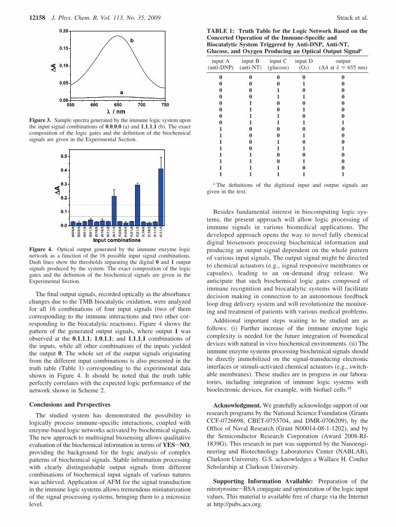
The final output signals, recorded optically as the absorbancechanges due to the TMB biocatalytic oxidation, were analyzedfor all 16 combinations of four input signals (two of themcorresponding to the immune interactions and two other cor-responding to the biocatalytic reactions). Figure 4 shows thepattern of the generated output signals, where output 1 wasobserved at the 0,1,1,1; 1,0,1,1; and 1,1,1,1 combinations ofthe inputs, while all other combinations of the inputs yieldedthe output 0. The whole set of the output signals originatingfrom the different input combinations is also presented in thetruth table (Table 1) corresponding to the experimental datashown in Figure 4. It should be noted that the truth tableperfectly correlates with the expected logic performance of thenetwork shown in Scheme 2.
Conclusions and Perspectives
The studied system has demonstrated the possibility tologically process immune-specific interactions, coupled withenzyme-based logic networks activated by biochemical signals.The new approach to multisignal biosensing allows qualitativeevaluation of the biochemical information in terms of YES-NO,providing the background for the logic analysis of complexpatterns of biochemical signals. Stable information processingwith clearly distinguishable output signals from differentcombinations of biochemical input signals of various natureswas achieved. Application of AFM for the signal transductionin the immune logic systems allows tremendous miniaturizationof the signal processing systems, bringing them to a microsizelevel.
Besides fundamental interest in biocomputing logic sys-tems, the present approach will allow logic processing ofimmune signals in various biomedical applications. Thedeveloped approach opens the way to novel fully chemicaldigital biosensors processing biochemical information andproducing an output signal dependent on the whole patternof various input signals. The output signal might be directedto chemical actuators (e.g., signal responsive membranes orcapsules), leading to an on-demand drug release. Weanticipate that such biochemical logic gates composed ofimmune recognition and biocatalytic systems will facilitatedecision making in connection to an autonomous feedbackloop drug delivery system and will revolutionize the monitor-ing and treatment of patients with various medical problems.
Additional important steps waiting to be studied are asfollows: (i) Further increase of the immune enzyme logiccomplexity is needed for the future integration of biomedicaldevices with natural in vivo biochemical environments. (ii) Theimmune enzyme systems processing biochemical signals shouldbe directly immobilized on the signal-transducing electronicinterfaces or stimuli-activated chemical actuators (e.g., switch-able membranes). These studies are in progress in our labora-tories, including integration of immune logic systems withbioelectronic devices, for example, with biofuel cells.18
Acknowledgment. We gratefully acknowledge support of ourresearch programs by the National Science Foundation (GrantsCCF-0726698, CBET-0755704, and DMR-0706209), by theOffice of Naval Research (Grant N00014-08-1-1202), and bythe Semiconductor Research Corporation (Award 2008-RJ-1839G). This research in part was supported by the Nanoengi-neering and Biotechnology Laboratories Center (NABLAB),Clarkson University. G.S. acknowledges a Wallace H. CoulterScholarship at Clarkson University.
Supporting Information Available: Preparation of thenitrotyrosine-BSA conjugate and optimization of the logic inputvalues. This material is available free of charge via the Internetat http://pubs.acs.org.
Figure 3. Sample spectra generated by the immune logic system uponthe input signal combinations of 0,0,0,0 (a) and 1,1,1,1 (b). The exactcomposition of the logic gates and the definition of the biochemicalsignals are given in the Experimental Section.
Figure 4. Optical output generated by the immune enzyme logicnetwork as a function of the 16 possible input signal combinations.Dash lines show the thresholds separating the digital 0 and 1 outputsignals produced by the system. The exact composition of the logicgates and the definition of the biochemical signals are given in theExperimental Section.
TABLE 1: Truth Table for the Logic Network Based on theConcerted Operation of the Immune-Specific andBiocatalytic System Triggered by Anti-DNP, Anti-NT,Glucose, and Oxygen Producing an Optical Output Signala
input A(anti-DNP)
input B(anti-NT)
input C(glucose)
input D(O2)
output(∆A at λ ) 655 nm)
0 0 0 0 00 0 0 1 00 0 1 0 00 0 1 1 00 1 0 0 00 1 0 1 00 1 1 0 00 1 1 1 11 0 0 0 01 0 0 1 01 0 1 0 01 0 1 1 11 1 0 0 01 1 0 1 01 1 1 0 01 1 1 1 1
a The definitions of the digitized input and output signals aregiven in the text.
12158 J. Phys. Chem. B, Vol. 113, No. 35, 2009 Strack et al.

References and Notes
(1) (a) Shao, X. G.; Jiang, H. Y.; Cai, W. S. Prog. Chem. 2002, 14,37–46. (b) Saghatelian, A.; Volcker, N. H.; Guckian, K. M.; Lin, V. S. Y.;Ghadiri, M. R. J. Am. Chem. Soc. 2003, 125, 346–347. (c) Ashkenasy, G.;Ghadiri, M. R. J. Am. Chem. Soc. 2004, 126, 11140–11141.
(2) (a) De Silva, A. P.; Uchiyama, S. Nat. Nanotechnol. 2007, 2, 399–410. (b) Credi, A. Angew. Chem., Int. Ed. 2007, 46, 5472–5475. (c) Pischel,U. Angew. Chem., Int. Ed. 2007, 46, 4026–4040.
(3) (a) Sivan, S.; Lotan, N. Biotechnol. Prog. 1999, 15, 964–970. (b)Sivan, S.; Tuchman, S.; Lotan, N. Biosystems 2003, 70, 21–33. (c)Deonarine, A. S.; Clark, S. M.; Konermann, L. Future Generation ComputerSystems 2003, 19, 87–97. (d) Ashkenazi, G.; Ripoll, D. R.; Lotan, N.;Scheraga, H. A. Biosens. Bioelectron. 1997, 12, 85–95. (e) Unger, R.; Moult,J. Proteins 2006, 63, 53–64.
(4) (a) Stojanovic, M. N.; Stefanovic, D.; LaBean, T.; Yan, H. InBioelectronics: From Theory to Applications; Willner, I., Katz, E., Eds.;Wiley-VCH: Weinheim, Germany, 2005; pp 427-455. (b) Saghatelian, A.;Volcker, N. H.; Guckian, K. M.; Lin, V. S. Y.; Ghadiri, M. R. J. Am. Chem.Soc. 2003, 125, 346–347. (c) Ashkenasy, G.; Ghadiri, M. R. J. Am. Chem.Soc. 2004, 126, 11140–11141.
(5) Win, M. N.; Smolke, C. D. Science 2008, 322, 456–460.
(6) Simpson, M. L.; Sayler, G. S.; Fleming, J. T.; Applegate, B. TrendsBiotechnol. 2001, 19, 317–323.
(7) Xu, J.; Tan, G. J. J. Comput. Theor. Nanosci. 2007, 4, 1219–1230.
(8) (a) Zhou, J.; Tam, T. K.; Pita, M.; Ornatska, M.; Minko, S.; Katz,E. ACS Appl. Mater. Interfaces 2009, 1, 144–149. (b) Privman, M.; Tam,T. K.; Pita, M.; Katz, E. J. Am. Chem. Soc. 2009, 131, 1314–1321. (c)Pita, M.; Katz, E. J. Am. Chem. Soc. 2008, 130, 36–37.
(9) Kramer, M.; Pita, M.; Zhou, J.; Ornatska, M.; Poghossian, A.;Schoning, M. J.; Katz, E. J. Phys. Chem. B 2009, 113, 2573–2579.
(10) (a) Tam, T. K.; Pita, M.; Ornatska, M.; Katz, E. Bioelectrochemistry2009, doi: 10.1016/j.bioelechem.2009.03.008. (b) Amir, L.; Tam, T. K.;Pita, M.; Meijler, M. M.; Alfonta, L.; Katz, E. J. Am. Chem. Soc. 2009,131, 826–832.
(11) (a) Tokarev, I.; Gopishetty, V.; Zhou, J.; Pita, M.; Motornov, M.;Katz, E.; Minko, S. ACS Appl. Mater. Interfaces 2009, 1, 532–536. (b)Motornov, M.; Zhou, J.; Pita, M.; Tokarev, I.; Gopishetty, V.; Katz, E.;Minko, S. Small 2009, 5, 817–820. (c) Pita, M.; Kramer, M.; Zhou, J.;Poghossian, A.; Schoning, M. J.; Fernandez, V. M.; Katz, E. ACS Nano2008, 2, 2160–2166. (d) Motornov, M.; Zhou, J.; Pita, M.; Gopishetty, V.;Tokarev, I.; Katz, E.; Minko, S. Nano Lett. 2008, 8, 2993–2997. (e) Pita,M.; Minko, S.; Katz, E. J. Mater. Sci.: Mater. Med. 2009, 20, 457-462.
(12) (a) Strack, G.; Pita, M.; Ornatska, M.; Katz, E. ChemBioChem 2008,9, 1260–1266. (b) Baron, R.; Lioubashevski, O.; Katz, E.; Niazov, T.;Willner, I. Org. Biomol. Chem. 2006, 4, 989–991. (c) Baron, R.; Liouba-shevski, O.; Katz, E.; Niazov, T.; Willner, I. J. Phys. Chem. A 2006, 110,8548–8553. (d) Baron, R.; Lioubashevski, O.; Katz, E.; Niazov, T.; Willner,I. Angew. Chem., Int. Ed. 2006, 45, 1572–1576.
(13) (a) Strack, G.; Ornatska, M.; Pita, M.; Katz, E. J. Am. Chem. Soc.2008, 130, 4234–4235. (b) Niazov, T.; Baron, R.; Katz, E.; Lioubashevski,O.; Willner, I. Proc. Natl. Acad. Sci. U.S.A. 2006, 103, 17160–17163.
(14) (a) Privman, V.; Strack, G.; Solenov, D.; Pita, M.; Katz, E. J. Phys.Chem. B 2008, 112, 11777–11784. (b) Privman, V.; Arugula, M. A.;Halamek, J.; Pita, M.; Katz, E. J. Phys. Chem. B 2009, 113, 5301–5310.
(15) (a) Crowther, J. R. ELISA: Theory and Practice; Humana Press:Totowa, NJ, 1995. (b) Crowther J. R. The ELISA Guidebook; Humana Press:Totowa, NJ, 2000.
(16) Pita, M.; Cui, L.; Gaikwad, R. M.; Katz, E.; Sokolov, I. Nano-technology 2008, 19, 375502.
(17) (a) Sokolov, I. In Cancer NanotechnologysNanomaterials forCancer Diagnosis and Therapy; Nalwa, H. S., Thomas Webster, T., Ed.;American Scientific Publishers: Los Angeles, CA, 2007: pp 43-59. (b)Iyer, S.; Gaikwad, R. M.; Subba-Rao, V.; Woodworth, C. D.; Sokolov, I.Nat. Nanotechnol. 2009, 4, 389–393. (c) Sokolov, I. Appl. Surf. Sci. 2003,210, 37–42. (d) Sokolov, I.; Iyer, S.; Subba-Rao, V.; Gaikwad, R. M.;Woodworth, C. D. Appl. Phys. Lett. 2007, 91, 023902.
(18) Tam, T. K.; Strack, G.; Pita, M.; Katz, E. J. Am. Chem. Soc. 2009,131, in press (DOI: 10.1021/ja9048459).
JP905620C
Logic Networks Based on Immunorecognition Processes J. Phys. Chem. B, Vol. 113, No. 35, 2009 12159