Viscous fluid universe filled with stiff fluid in general relativity
Upload
independentCategory
view
1download
0
Local field enhancement for high 2d order nonlinear
conversion from periodic Ag-coaxial nano-structures
filled by lithium niobate
Elsie Barakat,∗ Maria-Pilar Bernal, and Fadi Issam Baida
Département d’Optique P.M. Duffieux, Institut FEMTO-ST UMR 6174 CNRS Université de
Franche–Comté, 16 route de Gray, 25030 Besançon Cedex, France
E-mail: [email protected]
Abstract
Coaxial nano-patterned lithium niobate embedded in silver enable a large electromagnetic
confinement in the small volume cavities. The nonlinear material filling these cavities is at
the origin of high 2d order nonlinear conversion where no phase matching is needed. Doubly
resonant optical spectrum of the linear response is required in order to boost this phenomenon
providing a promising and stable SH device tailored for any desired wavelength. The struc-
ture is fabricated using E-beam lithography, dry etching and chemical mechanical polishing.
We report a SHG enhancement factor of 26 from 120nm thick nano-structured LiNbO3 com-
pared to 500µm un-patterned x−cut LiNbO3 wafer at λpump = 1550nm. The enhancement,
which comes exclusively from the nano-structured LiNbO3, is experimentally and theoreti-
cally demonstrated. A comparison between the SHG generated from an embedded structure
and that from three types of metallic sub-wavelength apertures is shown. The embedded struc-
ture shows strongest SH signal. Analysis of strong dependence of the SHG intensity on the in-
cident polarization with a home-made Three Dimensional Non-Linear Finite Difference Time
∗To whom correspondence should be addressed
1
Domain 3D-NL-FDTD algorithm including the nonlinear polarization shows good agreement
with the experimental data.
Introduction
Since the first nonlinear effect was experimentally observed by Franken et al.,1 shortly after the
demonstration of the first laser, nonlinear optics has been a growing field of research in recent
decades. Nonlinear optical phenomena occur when the response of a material system to an applied
field depends in a nonlinear behavior on the strength of the optical field. In the case of SHG, the in-
tensity of the light generated at the second frequency increases as the square of the intensity of the
applied laser light having small nonlinear efficiencies. Nevertheless, for other desired and poten-
tially new commercial devices, small light inducing nonlinear effects is required.2 This means that
the use of high-power incident light is less appropriated. For this reason, part of the research on
nonlinear phenomena is oriented to meta-materials3,4 where local field enhancement is exploited
and plays a significant role in increasing the nonlinear responses. SHG devices could potentially
be used as ultra-compact frequency converters in integrated photonic circuits. In addition, and as
it will be shown later, the polarization of light traveling through a nonlinear medium is sensitive
to its optical properties thereby, the study of polarization becomes a powerful tool in spectroscopy
for example.5
In a series of recent experiments, enhanced SHG signals were indeed observed in sub-wavelength
metallic nano-structures. Several shapes have been suggested for second order nonlinear op-
tics, such as T-shapes,6 G-shapes7 and many other nano-structures8–10 exploiting the strong field
enhancement and sub-wavelength confinement where a localized electric field enhancement is
achieved. This local field is attributed to the Extra-Ordinary Transmission (EOT) first reported
by Ebbesen11 and pursued by other authors.12–15 The EOT phenomena can be further obtained
by either the surface plasmon11 or guided mode excitation.16 In the first case, and due to the par-
ticularities of the evanescent wave, the electric field enhancement only occurs on and arround the
2
metal-dielectric interface. The guided mode, however, when excited at its cutoff frequency inside
the cavities, presents a small group velocity leading to a high confinement of the electric field over
all the cavity volume depending on the electromagnetic distribution of the guided mode. One of
the most suitable geometries for EOT generated by guided mode is the Annular Aperture Arrays
(AAA)17 made by silver where transmission can attend 95%.18 The T E11 guided mode is at the
origin of the enhanced transmission through the structure when illuminated at normal incidence. Its
corresponding cutoff wavelength depends on the geometrical parameters of the structure in particu-
lar the inner and the outer radii (λT E11 = f (Ro+Ri)). Furthermore, the ability of AAA structures to
support the T E11 mode and its harmonic resonant modes allows an efficient generation and propa-
gation of the harmonic fields when the apertures are filled with nonlinear material. While the metal
constituents lead to a strong localized field, nonlinearity is provided by the embedded nonlinear
material. In this work, lithium niobate is going to be the used nonlinear material. Our choice is
influenced by its multiple ways to modify its optical properties such as electro-optic, acousto-optic
and piezo-electric effects so that multi-functional micro-devices can be conceived. Moreover, this
active device is fabricated on the same substrate leading to the realization of integrated photonic
circuits. The combined effect of guided field enhancement and a strong nonlinear material opens
up new routes for the control of light matter interaction at the nanometer scale.
Few works have already proposed such kind of interaction between the EOT, and a nonlinear
material. For instance, SHG enhancement in a GaAs photonic crystal was reported by Osgood
group;19 the signal was 0.11 times as intense as that from z−cut lithium niobate. In a later work, a
periodic arrangement of sub-wavelength slits milled in Ag and filled with GaAs20 shows enhanced
conversion efficiency for SHG but the enhancement factor was not quantified. Note that the exci-
tation of the T E11 guided mode is not sufficient to enhance the SHG, a second mode located at the
harmonic wavelength is required in order to transmit the SH field outside the cavity.
In this work, guided modes inside the slits are also at the origin of the expected enhancement.
Nevertheless, the principle is completely different from what is proposed here because the excited
mode in the slits has no cutoff frequency and the expected enhancement remains well below what
3
one might expect with a frozen mode (guided mode at its cutoff frequency). We apply the con-
cept of a coupling confined field to lithium niobate as nonlinear material and we demonstrate an
enhancement factor of the generated second order nonlinear signal of up to ≈ 26 compared with
an un-patterned LiNbO3 surface. This result is 250 order of magnitude higher than that reported
by Osgood group.19 The geometrical parameters of the silver AAA are chosen here to have double
resonance due to the excitation of the T E11 -like mode at, first, its cutoff wavelength and, second,
at the harmonic of the fundamental mode i. e. Fabry-Perot (FP) resonance.
Results and discussion
The sample is fabricated on double face polished x-cut LiNbO3. First the LiNbO3 substrate is
coated with 280nm of positive tone PMMA - photoresist (PR). The coaxial shape on PR is de-
fined using E-beam lithography. After development, 100nm of chromium are deposited on the
patterned sample in order to form a metallic etch mask after liftoff. Reactive ion etching is used to
an-isotropically etch 120nm of LiNbO3. After etching, 300nm thick layer of silver is then evapo-
rated. Finally 180nm of silver are eliminated by Chemical Mechanical Polishing (CMP) until the
patterned LiNbO3 surface is reached. A scanning electron microscope (SEM) image of the final
structure is shown in Figure 1, along with a schematic of the structure. The square array pitch is
300nm, the coaxial inner and outer radii are 65nm and 135nm respectively. The distance between
two coaxial apertures is therefore 30nm and the gap width is 70nm. We have chosen silver because
it is less absorbent than other metals at the wavelength of telecommunication.21
As the transmission spectrum of such structure depends on its geometrical features, we have
chosen the design parameters so that its presents a double resonance: one at the pump wavelength
corresponding to the cutoff wavelength of the T E11 guided mode and the second at the first Fabry-
Perot (F-P) harmonic of the same mode for the SHG signal. A detailed analysis of the effect of the
geometrical parameters on the optical response of the given structure are described elsewhere.22,23
By exciting the T E11 guided mode, the group velocity almost vanishes and, as a consequence, the
4
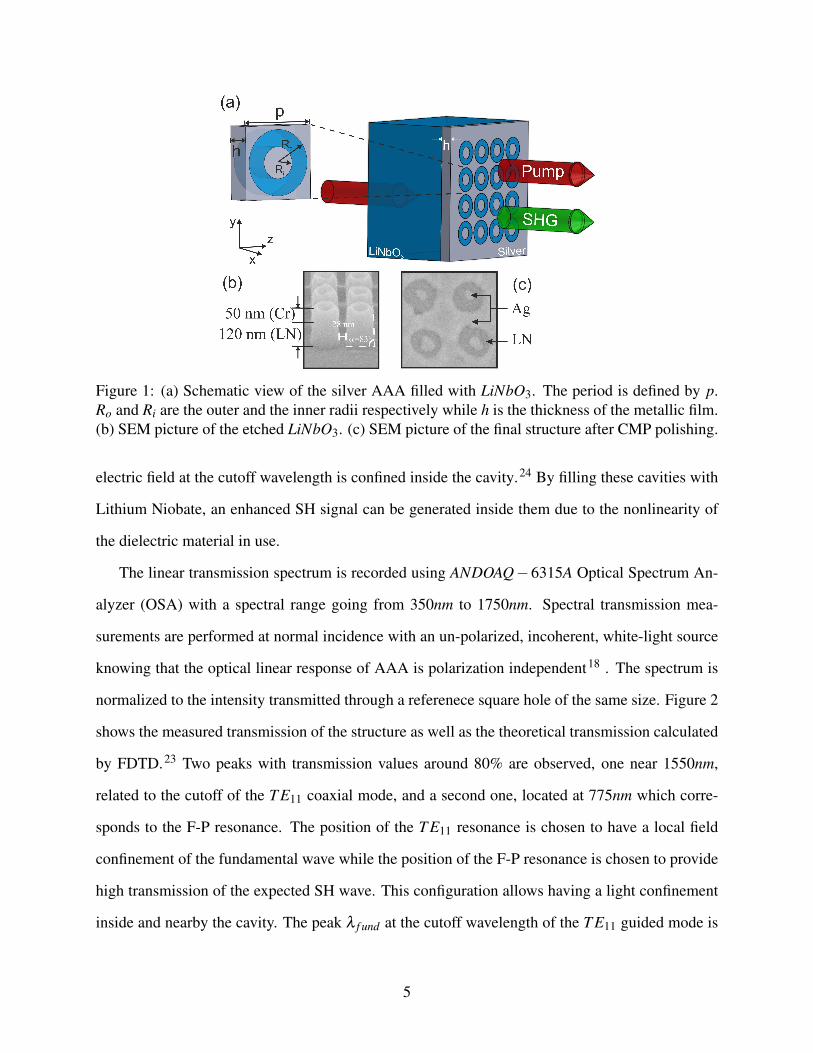
Figure 1: (a) Schematic view of the silver AAA filled with LiNbO3. The period is defined by p.Ro and Ri are the outer and the inner radii respectively while h is the thickness of the metallic film.(b) SEM picture of the etched LiNbO3. (c) SEM picture of the final structure after CMP polishing.
electric field at the cutoff wavelength is confined inside the cavity.24 By filling these cavities with
Lithium Niobate, an enhanced SH signal can be generated inside them due to the nonlinearity of
the dielectric material in use.
The linear transmission spectrum is recorded using ANDOAQ−6315A Optical Spectrum An-
alyzer (OSA) with a spectral range going from 350nm to 1750nm. Spectral transmission mea-
surements are performed at normal incidence with an un-polarized, incoherent, white-light source
knowing that the optical linear response of AAA is polarization independent18 . The spectrum is
normalized to the intensity transmitted through a referenece square hole of the same size. Figure 2
shows the measured transmission of the structure as well as the theoretical transmission calculated
by FDTD.23 Two peaks with transmission values around 80% are observed, one near 1550nm,
related to the cutoff of the T E11 coaxial mode, and a second one, located at 775nm which corre-
sponds to the F-P resonance. The position of the T E11 resonance is chosen to have a local field
confinement of the fundamental wave while the position of the F-P resonance is chosen to provide
high transmission of the expected SH wave. This configuration allows having a light confinement
inside and nearby the cavity. The peak λ f und at the cutoff wavelength of the T E11 guided mode is
5
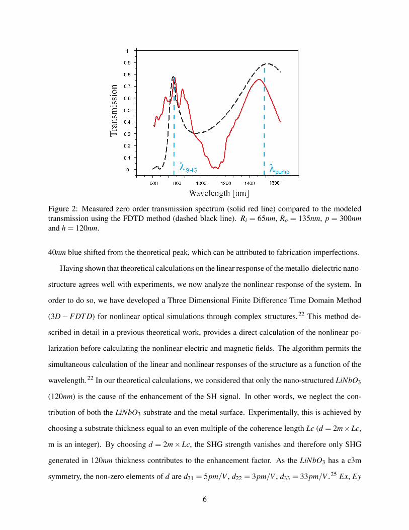
Figure 2: Measured zero order transmission spectrum (solid red line) compared to the modeledtransmission using the FDTD method (dashed black line). Ri = 65nm, Ro = 135nm, p = 300nmand h = 120nm.
40nm blue shifted from the theoretical peak, which can be attributed to fabrication imperfections.
Having shown that theoretical calculations on the linear response of the metallo-dielectric nano-
structure agrees well with experiments, we now analyze the nonlinear response of the system. In
order to do so, we have developed a Three Dimensional Finite Difference Time Domain Method
(3D−FDT D) for nonlinear optical simulations through complex structures.22 This method de-
scribed in detail in a previous theoretical work, provides a direct calculation of the nonlinear po-
larization before calculating the nonlinear electric and magnetic fields. The algorithm permits the
simultaneous calculation of the linear and nonlinear responses of the structure as a function of the
wavelength.22 In our theoretical calculations, we considered that only the nano-structured LiNbO3
(120nm) is the cause of the enhancement of the SH signal. In other words, we neglect the con-
tribution of both the LiNbO3 substrate and the metal surface. Experimentally, this is achieved by
choosing a substrate thickness equal to an even multiple of the coherence length Lc (d = 2m×Lc,
m is an integer). By choosing d = 2m×Lc, the SHG strength vanishes and therefore only SHG
generated in 120nm thickness contributes to the enhancement factor. As the LiNbO3 has a c3m
symmetry, the non-zero elements of d are d31 = 5pm/V , d22 = 3pm/V , d33 = 33pm/V .25 Ex, Ey
6
and Ez are the electric field vectors along x, y and z direction respectively. Since the d33 component
is the highest nonlinear coefficient, the relationship linking the dominant component (the two other
components of the vector are not zero) of the SH nonlinear polarization PNL to the electric field at
the pump wavelength is given by:25
PzNL = d31E2
x +d31E2y +d33E2
z (1)
Which means that the z field (// to the c.a.) plays a significant role in the contribution of
the corresponding polarization component and thus in the observed SH signal. In case of z−cut
wafer, the longitudinal component of the electric field (Ez(ω); component along the crystal axis)
at the pump wavelength is very weak and the contribution of PzNL is negligible. On the other
hand, for both x and y LiNbO3 wafer cuts, Ez(ω), the electric field component perpendicular to
the surface parallel to the crystal axis, is maximal. Therefore, the contribution of the d33 remains
significant leading to a high enhancement factor if the impinging light propagates along the optical
axis. Consequently, in order to obtain the highest SH strength, the predominant component of
the fundamental electric field should be multiplied by the d33 element of the simplified nonlinear
tensor thereby we choose x-cut wafer for our study.
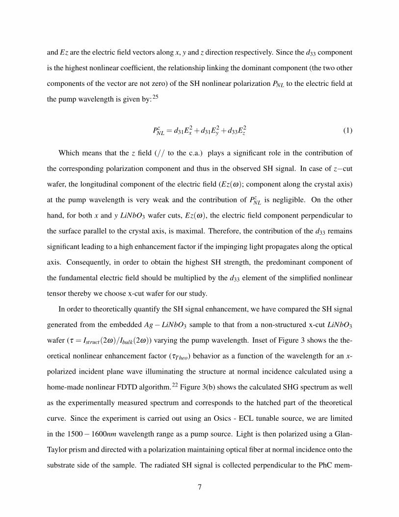
In order to theoretically quantify the SH signal enhancement, we have compared the SH signal
generated from the embedded Ag− LiNbO3 sample to that from a non-structured x-cut LiNbO3
wafer (τ = Istruct(2ω)/Ibulk(2ω)) varying the pump wavelength. Inset of Figure 3 shows the the-
oretical nonlinear enhancement factor (τT heo) behavior as a function of the wavelength for an x-
polarized incident plane wave illuminating the structure at normal incidence calculated using a
home-made nonlinear FDTD algorithm.22 Figure 3(b) shows the calculated SHG spectrum as well
as the experimentally measured spectrum and corresponds to the hatched part of the theoretical
curve. Since the experiment is carried out using an Osics - ECL tunable source, we are limited
in the 1500− 1600nm wavelength range as a pump source. Light is then polarized using a Glan-
Taylor prism and directed with a polarization maintaining optical fiber at normal incidence onto the
substrate side of the sample. The radiated SH signal is collected perpendicular to the PhC mem-
7
brane through a SPCM−AQR photon counter having a detection width of 700nm, 350−1050nm,
insuring that only SH radiation is detected.
Figure 3: SHG enhancement factor measured as a function of the wavelength, results correspondto the hatched part of the theoretical curve displayed in the inset. τ is defined by the SHG signalgenerated from the embedded structure is compared to that generated from un-patterned x−cutLiNbO3.
Several characteristic features of the SHG spectrum from the embedded structure can be no-
ticed. First, both theoretical and experimental results show a resonant peak at λSHmax = 750nm,
25nm blue-shifted from the half of the T E11 guided mode cutoff wavelength. The observed blue
shift is explained by surface plasmon resonance coupling to the T E11 guided mode, this fact is
numerically demonstrated by increasing the structure periodicity imposing the surface plasmon to
be located far from the transmission peak of the guided mode. In this latter case, the nonlinear
signal maximum is located at exactly half the fundemental wavelength. This phenomeneon is dif-
ferent from what described by Fan et al.19 where he attributed the shift phenomeneon to the point
dipole radiation. Second, both theory and experiment show that the SHG for the nano-patterned
LiNbO3 structure for an incident polarization parallel to the c. a. is ≈ 26 times enhanced with re-
spect to that from the x-cut bulk lithium niobate with no phase matching. This result is remarkable
especially taking into account that the thickness of the active NL material is only 120nm for the
embedded structure. In addition, this thin structure does not require complicated phase matching
8
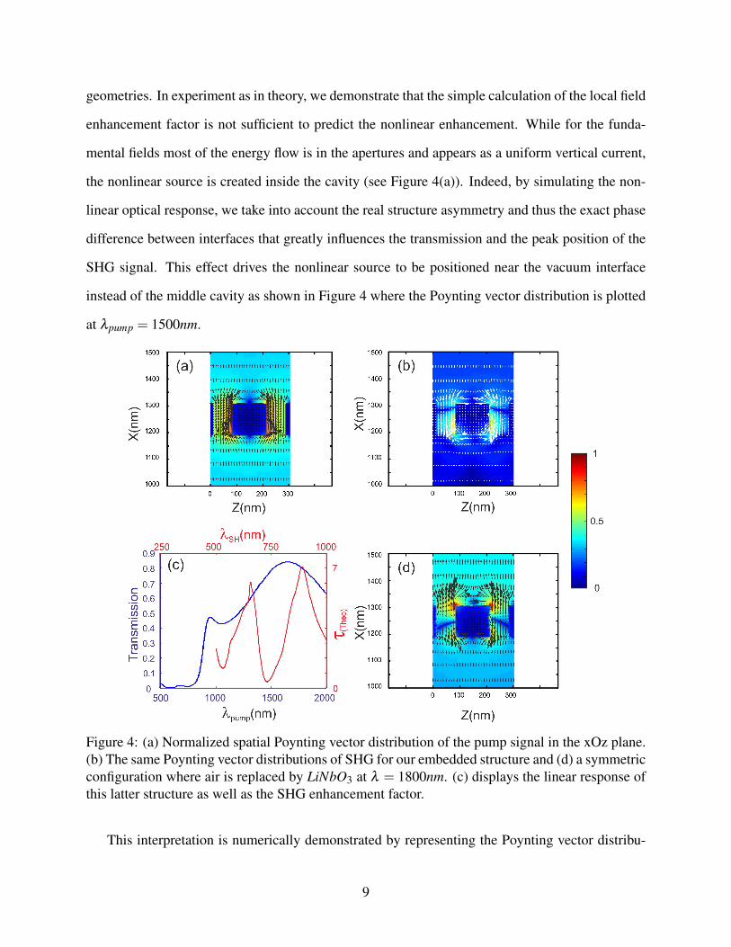
geometries. In experiment as in theory, we demonstrate that the simple calculation of the local field
enhancement factor is not sufficient to predict the nonlinear enhancement. While for the funda-
mental fields most of the energy flow is in the apertures and appears as a uniform vertical current,
the nonlinear source is created inside the cavity (see Figure 4(a)). Indeed, by simulating the non-
linear optical response, we take into account the real structure asymmetry and thus the exact phase
difference between interfaces that greatly influences the transmission and the peak position of the
SHG signal. This effect drives the nonlinear source to be positioned near the vacuum interface
instead of the middle cavity as shown in Figure 4 where the Poynting vector distribution is plotted
at λpump = 1500nm.
Figure 4: (a) Normalized spatial Poynting vector distribution of the pump signal in the xOz plane.(b) The same Poynting vector distributions of SHG for our embedded structure and (d) a symmetricconfiguration where air is replaced by LiNbO3 at λ = 1800nm. (c) displays the linear response ofthis latter structure as well as the SHG enhancement factor.
This interpretation is numerically demonstrated by representing the Poynting vector distribu-
9
tions for a symmetric embedded structure where the vacuum medium is replaced by LiNbO3. As
we can see from Figure 4, the nonlinear source is generated at almost the middle of the cavity
having comparable transmitted and reflected SH energy. However, a residual asymmetry persists
and is attributed to the propagation direction of the pump beam that breaks the symetry of the
problem. Figure 4 shows the linear transmission (blue curve) of the symmetrical structure as well
as the enhancement factor (red curve). One can see from the enhancement factor spectrum the
coupling between the plasmon resonance and the T E11 guided mode, this coupling leads to a small
enhancement factor (τT heo = 7 at λ = 1800nm).
In what follows, we will focus on the polarization dependence of the SHG process. As one can
see from Eq. (1), the intensity of SHG depends on both the wafer cut in use and the polarization
of the pumping light. When a linearly polarized light excites the sample, the highest SHG strength
is excited when the d33 component is oriented parallel to the crystal axis. This property, related to
the nonlinear anisotropic tensor of LiNbO3, is at the origin of the polarization dependence of the
SHG process.
Let α denote the angle between incident electric field and the Oz axis in the yOz plane. The
nonlinear polarization angular dependence has a cosine square dependence (PNL ∝ cosα2.I(ω)),
whereas in the case of a z-cut LiNbO3, this polarization dependence is more complicated and the
SHG strength is two order of magnitude smaller.22
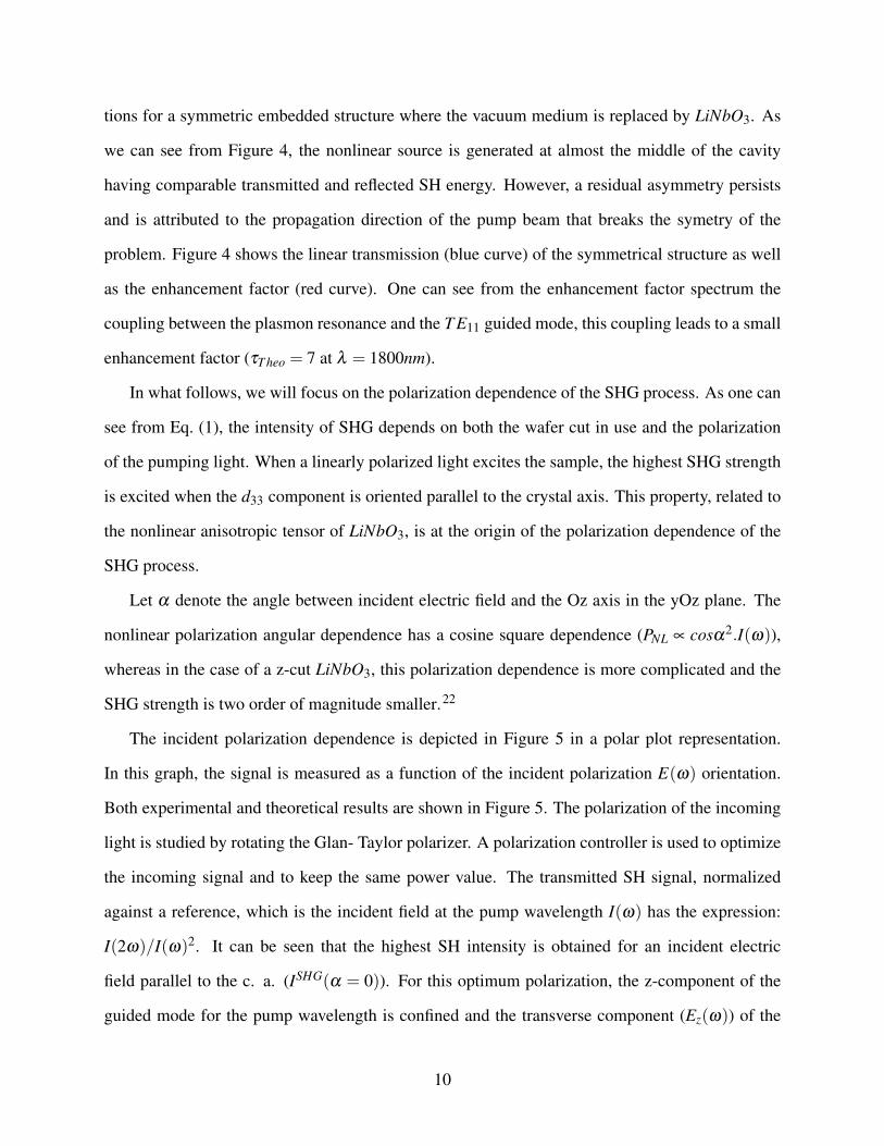
The incident polarization dependence is depicted in Figure 5 in a polar plot representation.
In this graph, the signal is measured as a function of the incident polarization E(ω) orientation.
Both experimental and theoretical results are shown in Figure 5. The polarization of the incoming
light is studied by rotating the Glan- Taylor polarizer. A polarization controller is used to optimize
the incoming signal and to keep the same power value. The transmitted SH signal, normalized
against a reference, which is the incident field at the pump wavelength I(ω) has the expression:
I(2ω)/I(ω)2. It can be seen that the highest SH intensity is obtained for an incident electric
field parallel to the c. a. (ISHG(α = 0)). For this optimum polarization, the z-component of the
guided mode for the pump wavelength is confined and the transverse component (Ez(ω)) of the
10
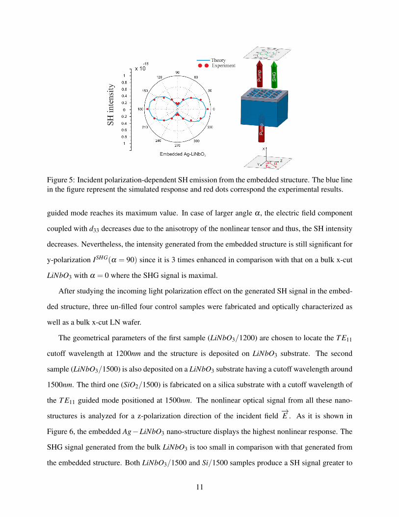
Figure 5: Incident polarization-dependent SH emission from the embedded structure. The blue linein the figure represent the simulated response and red dots correspond the experimental results.
guided mode reaches its maximum value. In case of larger angle α , the electric field component
coupled with d33 decreases due to the anisotropy of the nonlinear tensor and thus, the SH intensity
decreases. Nevertheless, the intensity generated from the embedded structure is still significant for
y-polarization ISHG(α = 90) since it is 3 times enhanced in comparison with that on a bulk x-cut
LiNbO3 with α = 0 where the SHG signal is maximal.
After studying the incoming light polarization effect on the generated SH signal in the embed-
ded structure, three un-filled four control samples were fabricated and optically characterized as
well as a bulk x-cut LN wafer.
The geometrical parameters of the first sample (LiNbO3/1200) are chosen to locate the T E11
cutoff wavelength at 1200nm and the structure is deposited on LiNbO3 substrate. The second
sample (LiNbO3/1500) is also deposited on a LiNbO3 substrate having a cutoff wavelength around
1500nm. The third one (SiO2/1500) is fabricated on a silica substrate with a cutoff wavelength of
the T E11 guided mode positioned at 1500nm. The nonlinear optical signal from all these nano-
structures is analyzed for a z-polarization direction of the incident field−→E . As it is shown in
Figure 6, the embedded Ag−LiNbO3 nano-structure displays the highest nonlinear response. The
SHG signal generated from the bulk LiNbO3 is too small in comparison with that generated from
the embedded structure. Both LiNbO3/1500 and Si/1500 samples produce a SH signal greater to
11
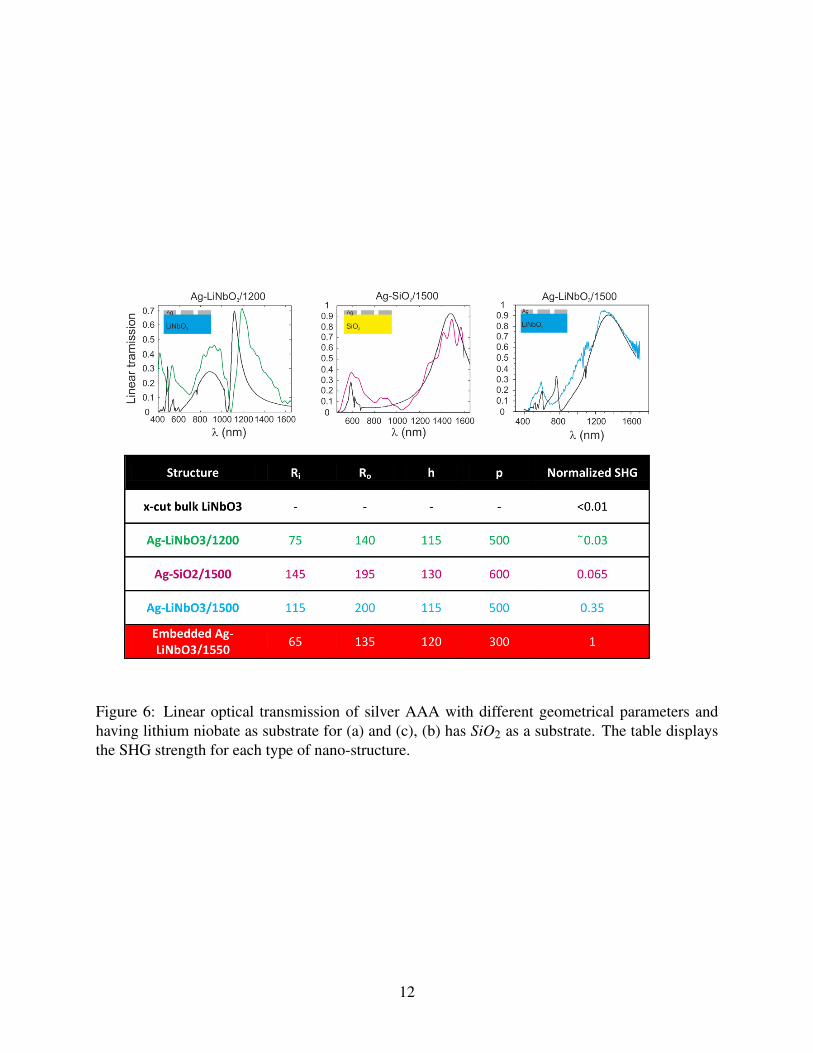
Figure 6: Linear optical transmission of silver AAA with different geometrical parameters andhaving lithium niobate as substrate for (a) and (c), (b) has SiO2 as a substrate. The table displaysthe SHG strength for each type of nano-structure.
12
that from LiNbO3/1200 demonstrating once again that the location of the T E11 cutoff wavelength
at the pump frequency is essential to considerably enhance the SHG signal. Moreover, by locating
the F-P resonance on the harmonic wavelength, the SH generated inside the cavity propagates and
can be transmitted outside the apertures.
In summary, we have experimentally observed an extraordinary enhanced SHG signal from
coaxial shape nano-structured lithium niobate combined with silver. The importance of choosing
the AAA structure is the ability to control separately the position of each resonance allowing us to
work at any desired wavelength. The SHG generated in far field is 26 times higher than that from x-
cut un-patterned LiNbO3. These results have been confirmed by nonlinear numerical simulations.
The linear response of the device shows a double resonance, one at the T E11 cutoff wavelength
and a second one at the harmonic wavelength. While the metal constituents lead to a strong lo-
calized field, nonlinearity is provided by the embedded LiNbO3. The experimental results show
excellent agreement with our calculations. These results also demonstrate that full understanding
of the nonlinear optical properties of nano-structures requires consideration of not only the local
field distribution at the pump wavelength but also the wafer cut of LiNbO3 in use and the polar-
ization properties of the incoming light. The relative strengths of the SHG signals with different
polarization combinations can be understood from the anisotropic behavior of the nonlinear tensor
of the lithium niobate material. To conclude, we have performed comparative studies of SH signal
in meta-materials with different parameters and established the largest nonlinear response in the
embedded Ag−LiNbO3.
Acknowledgement
We thank Cedric Villebasse from the IEF (Insitut d’Electronique Fondamentale) who trained the
author to use the CMP (Chemical Mechanical Polishing) machine in order to fabricate our device.
We also thank Roland Salut from ”la Central de Technologie MIMENTO, FEMTO-ST” for helpful
discussions and technical advice in device fabrication.
13
References
(1) Franken, P. A.; Hill, A. E.; Peters, C. W.; ; Weinreich, G. Phys. Rev. Lett. 1961, 7, 118–119.
(2) Menzel, R. Photonics Linear and Nonlinear Interactions of Laser Light and Matter; Springer,
2002.
(3) Smith, D. R.; Pendry, J. B.; Wiltshire, M. C. K. Science 2004, 305, 788.
(4) Enkrich, C.; Wegener, M.; Linden, S.; Burger, S.; Zschiedrich, L.; Schmidt, F.; Zhou, J. F.;
Koschny, T.; Soukoulis, C. M. Phys. Rev. Lett. 2005, 95, 203901.
(5) Kliger, D. S.; Lewis, J. W.; Randall, C. E. In Polarized light in Optics and Spectroscopy;
Inc., A. P., Ed.; Harcourt Brace Jovanovich publishers, 1990.
(6) Canfield, B. K.; Husu, H.; Laukkanen, J.; Bai, B.; Kuittinen, M.; Turunen, J.; ; Kauranen, M.
Nano Lett. 2007, 7, 1251–1255.
(7) Mamonov, E. A.; Murzina, T. V.; Kolmychek, I. A.; Maydykovsky, A. I.; Valev, V. K.; Sil-
hanek, A. V.; Ponizovskaya, E.; Bratkovsky, A.; Verbiest, T.; Moshchalkov, V. V.; ; Akt-
sipetrov, O. A. Opt. Lett. 2011, 36, 3681–3683.
(8) Zhou, R.; Lu, H.; Liu, X.; Gong, Y.; ; Mao, D. J. Opt. Soc. Am. B 2010, 27, 2405–2409.
(9) Klein, M. W.; Enkrich, C.; Wegener, M.; Linden, S. Science 2006, 313, 5786.
(10) Zeng, Y.; Hoyer, W.; Liu, J.; Koch, S. W.; ; Moloney, J. V. Phys. Rev. B 2009, 79, 235109–
235118.
(11) Ebbesen, T.; Lezec, H.; Ghaemi, H.; Thio, T.; ; and, P. W. Nature (London) 1998, 391, 667–
669.
(12) López-Rios, T.; Mendoza, D.; Garcia-Vidal, F. J.; Sánchez-Dehesa, J.; Pannetier, B. Phys.
Rev. Lett. 1998, 81, 665.
14

(13) Liu, H.; Lalanne, P. Nature (London) 2008, 452, 728–731.
(14) Baida, F.; Labeke, D. V.; Granet, G.; Moreau, A.; Belkhir, A. Appl. Phys. B 2004, 26, 1–8.
(15) Lezec, H. J.; Degiron, A.; Devaux, E.; Linke, R. A.; Martin-Moreno, L.; Garcia-Vidal, F. J.;
Ebbesen, T. W. Science 2002, 297, 5582.
(16) Baida, F. I.; Labeke, D. V. Phys. Rev. B 2003, 67, 155314–155317.
(17) Baida, F.; Labeke, D. V. Optics Commun. 2002, 209, 17–22.
(18) Poujet, Y.; Salvi, J.; Baida, F. I. Opt. Lett. 2007, 32, 2942–2944.
(19) Fan, W.; Zhang, S.; Panoiu, N.-C.; Abdenour, A.; Krishna, S.; Osgood, R. M.; Malloy, K. J.;
Brueck, S. R. J. Nano Lett. 2006, 6, 1027–1030.
(20) Vincenti, M. A.; de Ceglia, D.; Roppo, V.; Scalora, M. Opt. Express 2011, 19, 2064.
(21) Park, S.; Ju, J. J.; Kim, J. T.; su Kim, M.; Park, S. K.; Lee, J.-M.; Lee, W.-J.; ; Lee, M.-H.
Opt. Express 2009, 17, 697.
(22) Barakat, E.; Bernal, M.-P.; Baida, F. I. Opt. Express 2012, 20, 16258–16268.
(23) Barakat, E.; Bernal, M.-P.; Baida, F. I. Opt. Express 2010, 18, 6530–6536.
(24) Baida, F. I.; Belkhir, A.; Labeke, D. V. Phys. Rev. B 2006, 74, 205419.
(25) Shen, Y. R. The Principles of Nonlinear Optics; Wiley Interscience, 1984.
15
Copyright © 2022 FDOKUMEN