LLC+u ultrasonic water level control - SPX Cooling ...
12
LLC+u ultrasonic water level control INSTALLATION - OPERATION - MAINTENANCE Z1079969 ISSUED 10/2018 READ AND UNDERSTAND THIS MANUAL PRIOR TO OPERATING OR SERVICING THIS PRODUCT. user manual
-
Upload
khangminh22 -
Category
Documents
-
view
1 -
download
0
Transcript of LLC+u ultrasonic water level control - SPX Cooling ...
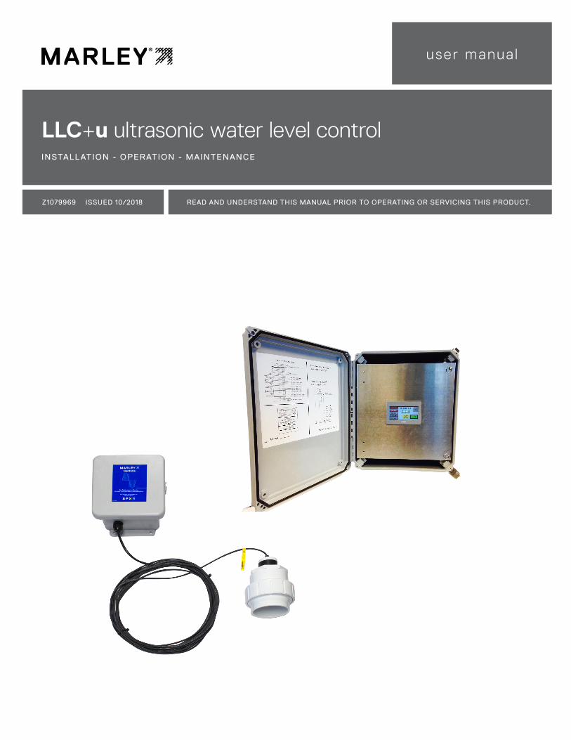
LLC+u ultrasonic water level controlINSTALLATION - OPERATION - MAINTENANCE
Z1079969 ISSUED 10/2018 READ AND UNDERSTAND THIS MANUAL PRIOR TO OPERATING OR SERVICING THIS PRODUCT.
user manua l

2
contents
System Diagram ..........................................................................................................4
Description ...................................................................................................................4
Programming ................................................................................................................6
Operation ......................................................................................................................9
Water Makeup Function ............................................................................................9
HAND-OFF-AUTO Switch ........................................................................................9
Troubleshooting ........................................................................................................10
Field Wiring - Parts List ..........................................................................................11
This manual contains vital information for the proper installation and operation of the LLC+u controls. Carefully read the manual be-fore installation or operation and follow all instructions. Save this manual for future reference.
Note
Indicates presence of a hazard which can cause severe personal injury, death or substantial property damage if ignored.
Indicates special instructions on installation, operation or mainte-nance which are important but not related to personal injury hazards.
Warning
Note
The following defined terms are used throughout this manual to bring attention to the presence of hazards of various risk levels, or to important information concerning the life of the product.

3
introduction
These instructions are intended to assure that field connections are completed properly and the control system operates for the maximum time possible. Since product warranty may depend on your actions, please read these instructions thoroughly prior to operation.
If you have questions about the operation and/or maintenance of this control system and you do not find the answers in this manual, please contact your Marley sales representative.
Hazard of electrical shock or burn. Be sure to turn off power to the panel before servicing. If working on equipment out of site of panel disconnect, lockout using standard lockout procedure.
Safety First
The Marley control system uses UL listed components installed in accordance with the National Electric Code. The location of the cooling tower and field installation of the control system can affect the safety of those responsible for installing, operating or maintaining the tower and controls. However, since SPX Cooling Technologies does not control the tower location, or field installation, we cannot be responsible for addressing safety issues that are affected by these items.
The following safety issues should be addressed by those responsible for installation, maintenance or repair of the tower and controls:
• Access to and from the control panel (including the customer supplied main disconnect/branch circuit protection.)
• Proper grounding of electrical control circuits.
• Sizing and protection of branch circuits feeding the control panel.
• Qualification of persons who will install, maintain and service the electri-cal equipment.
These are only some of the safety issues that may arise in the design and installation process. Marley strongly recommends that you consult a safety engineer to be sure that all safety considerations have been addressed.
Other safety issues are addressed in literature supplied with your tower. You should closely review the literature prior to installing, maintaining or repairing your tower.
Warning
Warning

4
description
The Liquid Level Control systems are used to accomplish five different functions:
• Water Makeup • High Water Alarm
• Low Water Alarm • High Water Cutoff
• Low Water Cutoff
The most common application of a water level control system is water makeup. The system regulates the amount of water in the tower basin and keeps it within normal operating levels. This makeup system is used to control a remotely installed water solenoid valve. When the water level drops below a prescribed, preset level, the solenoid valve is energized by the control system to fill the basin to its proper level.
LLC+u Control Panelwith Display
Sensor
30'-0 Lead 4-20mA level signal
High and low cut-off dry contacts
High and low alarm dry contacts
MU powered with 120V
EthernetSolenoid
Pump
Pump
BMS
StillingChamber
Basin Floor
6amp 120/1/60Utility Supply
JunctionBox
Extensionif required
Display
SYSTEM DIAGRAM
LLC Components Optional Field Components—by others
High and low water alarms can be utilized to give warn-ings associated with abnormal operating water levels. To provide indication of these types of alerts, the control sys-tem provides dry contacts to interface with various digital control systems or can be connected to user supplied alarm indicators to signal when corrective action is required.
Low-water cutoffs are commonly used to protect pumps from operating without sufficient water. When used in unattended operating environments, the low-water cutoff is configured to shut the pump off, thus preventing costly repairs. Dry contacts can be wired directly in series with pilot duty controls or to digital control systems to initiate the shutdown of protected equipment during low-water situations.

5
description
Route incoming power cable from the bottom of the enclosure up into the top (line) side of the main circuit breaker.
Circuit breaker powers a remote solenoid.
H-O-A selector switch for makeup solenoid circuit.
If a makeup solenoid circuit is provided, connect the solenoid wires here at points 4A and 2A. This circuit provides 120 VAC power for the solenoid.
Seal field-added conduit holes with silicone or expanding foam to create a vapor barrier to prevent water vapor inside the enclosure.
4 - 2 0 m A o u t p u t s i g n a l representing actual water level for remote BMS monitoring.
Connect alarm and/or cutoff control wiring to the grey terminal points.
Ultrasonic sensor wiring.
Selector Switch Operation
HAND: position: Solenoid will energize. OFF: position: Solenoid is de-energized
AUTO: Solenoid will operate depending on water level in relation to water probe height.

6
programming
SCREEN LAYOUT
Red indicates the relay inside the control panel has been energized.
LEVEL IN INCHES–actual water level in the cold water basin
GOTO SETUP–use to program sensor heights and setpoint levels. Default password is 1492
INFO–use to see programmed levels
Requires field programming
1. Measure and program the distance between sensor and water basin floor
2 Program the water level setpoints
3. Operate WATER MAKE UP selector switch to operate solenoid valve circuit
The WATER MAKE UP selector switch controls the makeup solenoid circuit
HAND position–manually energizes remote makeup solenoid
OFF position–no power to remote makeup solenoid
AUTO position–ultrasonic makeup water level sensor activated
Note

7
programming
Feeder breaker powers the remote solenoid.
Main circuit breaker powers the control panel
PROGRAMMING STEPS
Power ON the control panel circuits by moving the switches on the two circuit breakers to the up position.
Measure the distance from the bottom of the ultrasonic sensor to the basin floor.
Access the program by pressing GOTO SETUP
Press the light blue screen cell under ENTER PASSWORD bringing up a yellow keypad then enter password 1492 (factory default password) and press ENT to access the setup screens.
BOTTOM OF SENSORTO BASIN FLOOR
1"
CIRCUIT PROTECTION
➠

8
programming
Press the light blue screen cell to right of SENSOR HEIGHT to bring up a yellow keypad then enter the sensor height in inches. Sensor height is from bottom of the sensor to basin floor (or bottom of PVC tubing in case of an external stilling chamber.
Press the NEXT button to enter additional programming screens.
On each screen, enter the water level setpoint values by pressing the light blue cell and entering a value on the yellow keypad then press ENT to save.
Recommended levels are unique for every cooling tower and are available from your Marley sales representative.
When finished press GO TO MAIN to return to main screen.
On the main screen are view actual water level and relay actions. The reac-tion time is purposely slow to allow time for the system to react and refresh the screens.

9
operation
OperationThe LLC+u water level control system consists of an ultrasonic sensor placed to measure the water level in the cold water basin. The senor is typically located inside the cooling tower or on some cooling towers in an external chamber. A PLC with HMI touch screen is used to program water level heights and offers a visual indication of the water level. Internal relays with form "C" contacts are used as switches, one for each water setpoint.
Programming is accomplished in the field based on recommended cooling tower water level heights. Contact your Marley sales representative for recom-mended setpoint levels. The sensor is programmed with a height from sensor to bottom of the basin floor. Individual setpoint levels are programmed for high cutoff, high alarm, makeup, low alarm and low cut off.
Alarm set point may be used to complete a remote BMS alarm circuit. Cut off set point may be used to shut of a circulating pump.
A 4-20mA output is provided for BMS remote monitoring of water level
Water Makeup FunctionThe circuitry for water makeup in the LLC+u control panel provides an inde-pendent circuit breaker for direct connection to a 110-120VAC water solenoid valve. This added feature allows customer installation without having to provide an additional power circuit to energize the solenoid. The solenoid is connected to terminals 2A and 4A as represented on the control’s specific wiring diagram.
Purpose and Function of the HAND-OFF-AUTO SwitchLocated on the right side of the control’s enclosure is a HAND-OFF-AUTO switch. This switch is used primarily at cooling tower startup and in maintenance procedures where the tower basin is empty or has been drained. When the tower’s basin needs to be manually filled, the switch is placed in the HAND position. This selection bypasses the probe assembly’s feedback and directly energizes the solenoid valve connected to the water supply. Once the cooling tower basin is filled, the switch is placed in the AUTO position to allow the adjusted ultrasonic sensor to monitor and sustain the proper operating level. Placing the switch in the OFF position completely interrupts any monitoring or fill action normally provided by the LLC+u control panel. Normal tower operation depends upon the HAND-OFF-AUTO switch being positioned in the AUTO mode at all times.

10
troubleshooting
The control panel has been factory tested before shipment and most issues lie outside of the control panel e.g. proper field wiring connections to the control panel.
In an effort to troubleshoot the system, please check the following:
• The two circuit breakers must be energized with operating handles in the up position
• The unit requires programming in the field. See programming instruc-tions in this manual. The ultrasonic sensor head does not require any field programming.
• Check water make up selector switch position.
• Confirm the two sensor wires are oriented and correctly connected at terminal points in the control panel assuring the terminal connection does not land on the insulation of the sensor wire. Strip back just enough wire insulation so you can see some copper wire exposed assuring a metal-to-metal connection.
• The sensor wire is a four wire plus shielded cord. The red and black wires connect to terminal points 24 and 13. The shield connects to ground. Always refer to the as-built wiring diagram on the inside door panel for current connection points. Tape back the white and green wires that are not used.
• If sensor wires were extended in the field, check to make sure the exten-sion wires were numbered correctly and connections secure.
• Assure no external power wiring from other devices run in parallel with the sensor wiring. Follow best practice wiring for power and instrumentation wiring placements.
Checking the power circuit for the makeup solenoid
• Rotate the WATER MAKE UP selector switch to the HAND position. The solenoid should energize allowing makeup water to flow into the cooling loop. Inside the control panel is a single-pole circuit breaker, which must be in the ON position to power the circuit.

11
field wiring - parts list
Part Number Description
2599336 120 VAC Ultrasonic LLC+u Control Panel
2588880 DL10 Ultrasonic sensor only with 30 ft cable (no junction box or fittings)
2586100DL10 Ultrasonic sensor with 30 ft cable, junction box and 3" union slip fitting for round PVC stilling
chamber located external to the cooling tower
2599330DL10 Ultrasonic sensor with 30 ft cable, junction box and 3" threaded fitting for square metal stilling
chamber located internal to the cooling tower
2586086 100 ft 4-18 AWG PVC cable
2586087 150 ft 4-18 AWG PVC cable
2586088 200 ft 4-18 AWG PVC cable
120 VAC LINE VOLTAGE
2 POLE6AMP
HO
T
GN
D
NEU
TRA
L
Wiring diagram is typical. Refer to wiring diagram on inside of the enclosure door for actual as-built wiring diagram, which may include project specific options.
Wire 120 VAC incoming voltage supply to line side (top) of the main 2 pole circuit breaker CB1 and CB2
Wire 120 VAC remote makeup solenoid to terminal points 2A and 4A
Wire alarm and cutoff circuits to terminal points 5 through 22 as needed
Wire ultrasonic sensor:
• Red to terminal point +24
• Black to terminal point 13
• Shield to GND (Do not ground shield any other location, only at the LLC+u control panel)
• The white and green sensor wires are not used.
Wire 4-20mA output signal representing the water level in basin from points 4-20+ and 4-20- to customers BMS system.

Z1079969 | ISSUED 10/2018
©2018 SPX COOLING TECHNOLOGIES | ALL RIGHTS RESERVED
In the interest of technological progress, all products are subject to design
and/or material change without notice.
LLC+u water level controlUS E R MAN UAL
SPX COOLING TECHNOLOGIES, INC.
7401 WEST 129 STREET
OVERLAND PARK, KS 66213 USA
913 664 7400 | [email protected]
spxcooling.com