Liquiphant M/S with electronic insert FEL57 + Nivotester ...
40
Point level measuring system Products Solutions Services Special Documentation Liquiphant M/S with electronic insert FEL57 + Nivotester FTL325P Functional Safety Manual SD01508F/00/EN/03.17 71386529 CH1 CH1 [Ex ia] CH1 CH2 CH2 CH3 CH3 [Ex ia]
-
Upload
khangminh22 -
Category
Documents
-
view
3 -
download
0
Transcript of Liquiphant M/S with electronic insert FEL57 + Nivotester ...
Point level measuring system
Products Solutions Services
Special DocumentationLiquiphant M/S with electronicinsert FEL57 + NivotesterFTL325PFunctional Safety Manual
SD01508F/00/EN/03.1771386529
CH1
CH1
[Ex ia]
CH1
CH2
CH2
CH3
CH3
[Ex ia]

Liquiphant M/S with electronic insert FEL57 + Nivotester FTL325P
2 Endress+Hauser
Table of contents
Declaration of conformity . . . . . . . . . . . . . . . . . . . . . 3General . . . . . . . . . . . . . . . . . . . . . . . . . . . . . . . . . . . . 5Other safety-related characteristic values . . . . . . . . . . . . . 5Useful lifetime of electrical components . . . . . . . . . . . . . . 12
Certificate . . . . . . . . . . . . . . . . . . . . . . . . . . . . . . . . 13
Document information . . . . . . . . . . . . . . . . . . . . . . 14Document function . . . . . . . . . . . . . . . . . . . . . . . . . . . 14Symbols used . . . . . . . . . . . . . . . . . . . . . . . . . . . . . . . 14Supplementary device documentation . . . . . . . . . . . . . . . 15
Permitted devices types . . . . . . . . . . . . . . . . . . . . . 16SIL label on the nameplate . . . . . . . . . . . . . . . . . . . . . . 17
Safety function . . . . . . . . . . . . . . . . . . . . . . . . . . . . 18Definition of the safety function . . . . . . . . . . . . . . . . . . . 18Restrictions for use in safety-related applications . . . . . . . 18
Use in safety instrumented systems . . . . . . . . . . . . 21Device behavior during operation . . . . . . . . . . . . . . . . . . 21Device configuration for safety-related applications . . . . . . 21Proof-testing . . . . . . . . . . . . . . . . . . . . . . . . . . . . . . . 25
Life cycle . . . . . . . . . . . . . . . . . . . . . . . . . . . . . . . . . 32Requirements for personnel . . . . . . . . . . . . . . . . . . . . . 32Installation . . . . . . . . . . . . . . . . . . . . . . . . . . . . . . . . . 32Operation . . . . . . . . . . . . . . . . . . . . . . . . . . . . . . . . . 32Maintenance . . . . . . . . . . . . . . . . . . . . . . . . . . . . . . . 32Repair . . . . . . . . . . . . . . . . . . . . . . . . . . . . . . . . . . . . 32Modification . . . . . . . . . . . . . . . . . . . . . . . . . . . . . . . . 33Decommissioning . . . . . . . . . . . . . . . . . . . . . . . . . . . . 33
Appendix . . . . . . . . . . . . . . . . . . . . . . . . . . . . . . . . 34Structure of the measuring system . . . . . . . . . . . . . . . . . 34Commissioning or proof test report . . . . . . . . . . . . . . . . . 36Further information . . . . . . . . . . . . . . . . . . . . . . . . . . . 37Version history . . . . . . . . . . . . . . . . . . . . . . . . . . . . . . 37
Liquiphant M/S with electronic insert FEL57 + Nivotester FTL325P
Endress+Hauser 3
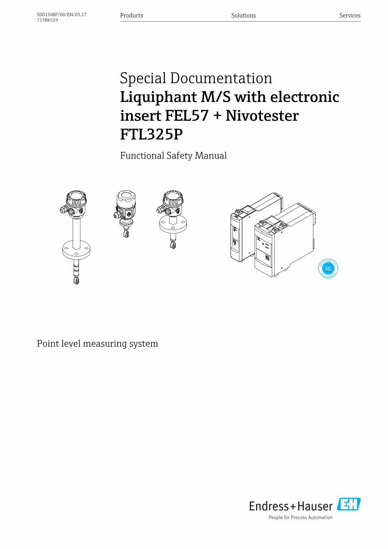
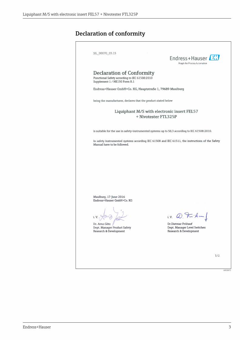
Declaration of conformity
A0028072
Liquiphant M/S with electronic insert FEL57 + Nivotester FTL325P
4 Endress+Hauser
A0028073

Liquiphant M/S with electronic insert FEL57 + Nivotester FTL325P
Endress+Hauser 5
General The components can be operated as different versions:• Version II (→ 6)
One Liquiphant with a 1-channel Nivotester, for the activation of an actuator or a safety-relatedPLC via switching contacts, for instance
• Version III (→ 7)One Liquiphant with a 3-channel Nivotester, switching contacts are switched in series
• Version IV (→ 8)Two Liquiphant devices with a 3-channel Nivotester, switching contacts are switched in series
• Version V (→ 10)Three Liquiphant devices with a 3-channel Nivotester; evaluation is performed in a safety-relatedPLC, for example
• Version VI (→ 12)Three Liquiphant devices with a 3-channel Nivotester, only channel 1 has a SIL-specificmonitoring function. Channels 2 and 3 are used for level control of the same level (e.g. Δs). Thislevel control may not then be considered as a safety measure as part of functional safety accordingto EN 61508.
NOTICEMeasuring another, independent level (e.g. in a second tank)‣ The remaining channels may not be used for other levels.
Other safety-relatedcharacteristic values
Please note the following for the tables below:• A common cause factor β = 10 % has been assumed in the calculations indicated below.• For multi-channel systems, the PFDavg values already contain common cause failures for the
specific wiring scheme.• The PFDavg values only apply to the particular wiring scheme for which the values have been
calculated. They are not a suitable basis for making calculations for other wiring schemes.The use of NC contacts instead of NO contacts, in particular, is not permitted for operationaccording to SIL specifications.
• The wiring scheme indicates the number of devices and the circuitry of the level relaycontacts (open when required (demand mode)).
• If there are several devices in a wiring scheme, all the devices have the same settings shown.• The tables show safety-related values and wiring options for the measuring system.• FIT = Failure in Time, 1 FIT = 10-9 l/h.
Liquiphant M/S with electronic insert FEL57 + Nivotester FTL325P
6 Endress+Hauser
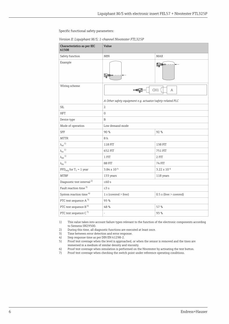
Specific functional safety parameters:
Version II: Liquiphant M/S; 1-channel Nivotester FTL325P
Characteristics as per IEC61508
Value
Safety function MIN MAX
Example
Wiring schemeACH1
A Other safety equipment e.g. actuator/safety-related PLC
SIL 2
HFT 0
Device type B
Mode of operation Low demand mode
SFF 90 % 92 %
MTTR 8 h
λsd 1) 118 FIT 138 FIT
λsu 1) 652 FIT 751 FIT
λdd 1) 1 FIT 2 FIT
λdu 1) 88 FIT 74 FIT
PFDavg for T1 = 1 year 3.84 x 10⁻⁴ 3.22 x 10⁻⁴
MTBF 133 years 118 years
Diagnostic test interval 2) ≤60 s
Fault reaction time 3) ≤3 s
System reaction time 4) 1 s (covered > free) 0.5 s (free > covered)
PTC test sequence A 5) 93 %
PTC test sequence B 6) 48 % 57 %
PTC test sequence C 7) - 93 %
1) This value takes into account failure types relevant to the function of the electronic components accordingto Siemens SN29500.
2) During this time, all diagnostic functions are executed at least once.3) Time between error detection and error response.4) Step response time as per DIN EN 61298-2.5) Proof test coverage when the level is approached, or when the sensor is removed and the tines are
immersed in a medium of similar density and viscosity.6) Proof test coverage when simulation is performed on the Nivotester by activating the test button.7) Proof test coverage when checking the switch point under reference operating conditions.

Liquiphant M/S with electronic insert FEL57 + Nivotester FTL325P
Endress+Hauser 7
Version III: Liquiphant M/S; 3-channel Nivotester FTL325P, CH2 and CH3 in series
Characteristics as per IEC61508
Value
Safety function MIN MAX
Example
Wiring scheme
A
B C
A
(1oo2)
CH2 CH2
CH3 CH3
CH1 CH1
A Other safety equipment e.g. actuator/safety-related PLCB Possibility 1C Possibility 2; 1oo2 assessment
SIL 2
HFT 0
Device type B
Mode of operation Low demand mode
SFF 95 % 96 %
MTTR 8 h
λsd 1) 128 FIT 149 FIT
λsu 1) 856 FIT 954 FIT
λdd 1) 1 FIT 2 FIT
λdu 1) 56 FIT 43 FIT
PFDavg for T1 = 1 year 2.46 x 10⁻⁴ 1.88 x 10⁻⁴
MTBF 110 years 100 years
Diagnostic test interval 2) ≤60 s
Fault reaction time 3) ≤3 s
System reaction time 4) 1 s (covered > free) 0.5 s (free > covered)
PTC test sequence A 5) 95 %
PTC test sequence B 6) 63 % 70 %
PTC test sequence C 7) - 95 %
1) This value takes into account failure types relevant to the function of the electronic components accordingto Siemens SN29500.
2) During this time, all diagnostic functions are executed at least once.3) Time between error detection and error response.4) Step response time as per DIN EN 61298-2.5) Proof test coverage when the level is approached, or when the sensor is removed and the tines are
immersed in a medium of similar density and viscosity.6) Proof test coverage when simulation is performed on the Nivotester by activating the test button.7) Proof test coverage when checking the switch point under reference operating conditions.
Liquiphant M/S with electronic insert FEL57 + Nivotester FTL325P
8 Endress+Hauser
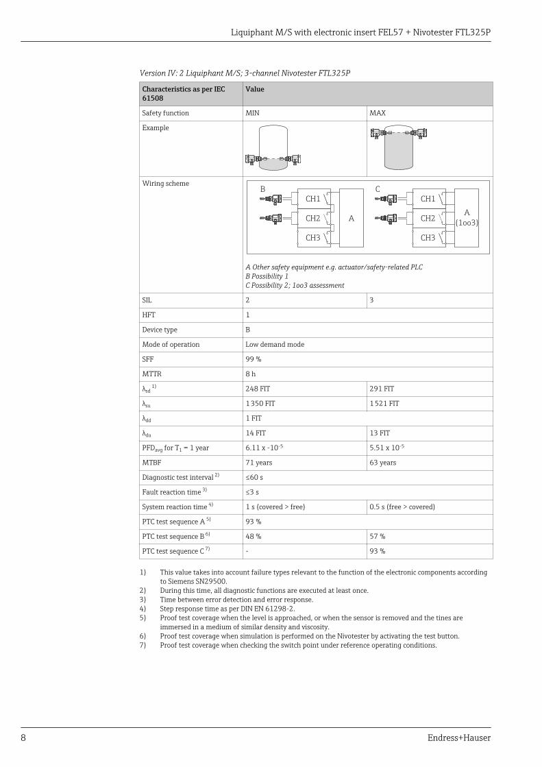
Version IV: 2 Liquiphant M/S; 3-channel Nivotester FTL325P
Characteristics as per IEC61508
Value
Safety function MIN MAX
Example
Wiring scheme
A
B C
A
(1oo3)CH2 CH2
CH3 CH3
CH1 CH1
A Other safety equipment e.g. actuator/safety-related PLCB Possibility 1C Possibility 2; 1oo3 assessment
SIL 2 3
HFT 1
Device type B
Mode of operation Low demand mode
SFF 99 %
MTTR 8 h
λsd 1) 248 FIT 291 FIT
λsu 1 350 FIT 1 521 FIT
λdd 1 FIT
λdu 14 FIT 13 FIT
PFDavg for T1 = 1 year 6.11 x -10-5 5.51 x 10⁻⁵
MTBF 71 years 63 years
Diagnostic test interval 2) ≤60 s
Fault reaction time 3) ≤3 s
System reaction time 4) 1 s (covered > free) 0.5 s (free > covered)
PTC test sequence A 5) 93 %
PTC test sequence B 6) 48 % 57 %
PTC test sequence C 7) - 93 %
1) This value takes into account failure types relevant to the function of the electronic components accordingto Siemens SN29500.
2) During this time, all diagnostic functions are executed at least once.3) Time between error detection and error response.4) Step response time as per DIN EN 61298-2.5) Proof test coverage when the level is approached, or when the sensor is removed and the tines are
immersed in a medium of similar density and viscosity.6) Proof test coverage when simulation is performed on the Nivotester by activating the test button.7) Proof test coverage when checking the switch point under reference operating conditions.

Liquiphant M/S with electronic insert FEL57 + Nivotester FTL325P
Endress+Hauser 9
The failure rates are based on an analysis in accordance with DIN EN 61508-6: 2011-02, TableD.4, "Using the β-factor to calculate the probability of failure in an E/E/PE safety-related systemdue to common cause failures". The calculation gives a β-factor of 10 %. This factor is based onthe failure rates indicated above. If additional measures are implemented during installation toprevent common cause errors as defined in Table D.1, the β-factor can possibly be reduced to5 %. Possible measures are:• Sensors installed in a physically separate location• Cable routed separately between the Liquiphant and Nivotester• Separate protection from environmental influences: impact, sunshine, EMC protection and/or
overvoltage• Use of different sensor materials, and combination of high-temperature and normal version

Liquiphant M/S with electronic insert FEL57 + Nivotester FTL325P
10 Endress+Hauser
Version IV: 3 Liquiphant M/S; 3-channel Nivotester FTL325P
Characteristics as per IEC61508
Value
Safety function MIN MAX
Example
Wiring scheme
A
(2oo3)CH2
CH3
CH1
A Other safety equipment e.g. actuator/safety-related PLC; 2oo3 assessment
SIL 2 3
HFT 1
Device type B
Mode of operation Low demand mode
SFF 99 %
MTTR 8 h
λsd 1) 366 FIT 430 FIT
λsu 1 556 FIT 1 812 FIT
λdd 1 FIT
λdu 16 FIT 15 FIT
PFDavg for T1 = 1 year 7.03 x -10-5 6.35 x 10⁻⁵
MTBF 59 years 51 years
Diagnostic test interval 2) ≤60 s
Fault reaction time 3) ≤3 s
System reaction time 4) 1 s (covered > free) 0.5 s (free > covered)
PTC test sequence A 5) 93 %
PTC test sequence B 6) 48 % 57 %
PTC test sequence C 7) - 93 %
1) This value takes into account failure types relevant to the function of the electronic components accordingto Siemens SN29500.
2) During this time, all diagnostic functions are executed at least once.3) Time between error detection and error response.4) Step response time as per DIN EN 61298-2.5) Proof test coverage when the level is approached, or when the sensor is removed and the tines are
immersed in a medium of similar density and viscosity.6) Proof test coverage when simulation is performed on the Nivotester by activating the test button.7) Proof test coverage when checking the switch point under reference operating conditions.

Liquiphant M/S with electronic insert FEL57 + Nivotester FTL325P
Endress+Hauser 11
The failure rates are based on an analysis in accordance with DIN EN 61508-6: 2011-02, TableD.4, "Using the β-factor to calculate the probability of failure in an E/E/PE safety-related systemdue to common cause failures". The calculation gives a β-factor of 10 %. This factor is based onthe failure rates indicated above. If additional measures are implemented during installation toprevent common cause errors as defined in Table D.1, the β-factor can possibly be reduced to5 %. Possible measures are:• Sensors installed in a physically separate location• Cable routed separately between the Liquiphant and Nivotester• Separate protection from environmental influences: impact, sunshine, EMC protection and/or
overvoltage• Use of different sensor materials, and combination of high-temperature and normal version
Liquiphant M/S with electronic insert FEL57 + Nivotester FTL325P
12 Endress+Hauser
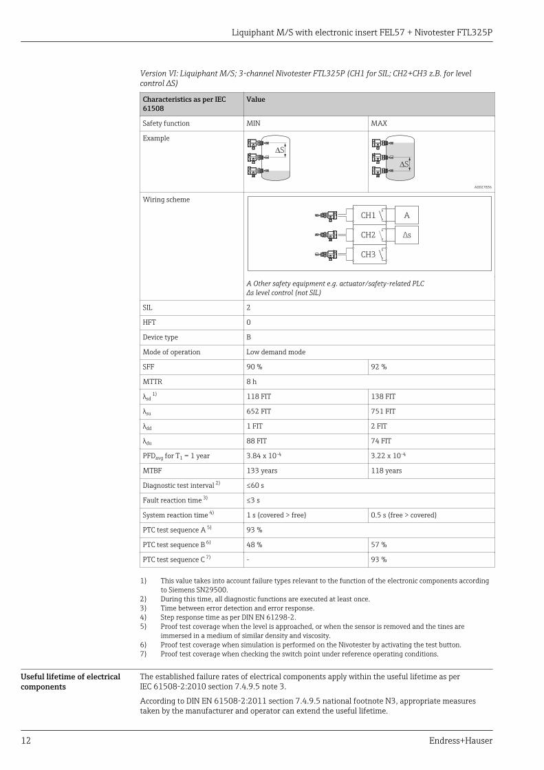
Version VI: Liquiphant M/S; 3-channel Nivotester FTL325P (CH1 for SIL; CH2+CH3 z.B. for levelcontrol ΔS)
Characteristics as per IEC61508
Value
Safety function MIN MAX
Example
DS
DS
A0027836
Wiring scheme
A
∆sCH2
CH3
CH1
A Other safety equipment e.g. actuator/safety-related PLCΔs level control (not SIL)
SIL 2
HFT 0
Device type B
Mode of operation Low demand mode
SFF 90 % 92 %
MTTR 8 h
λsd 1) 118 FIT 138 FIT
λsu 652 FIT 751 FIT
λdd 1 FIT 2 FIT
λdu 88 FIT 74 FIT
PFDavg for T1 = 1 year 3.84 x 10⁻⁴ 3.22 x 10⁻⁴
MTBF 133 years 118 years
Diagnostic test interval 2) ≤60 s
Fault reaction time 3) ≤3 s
System reaction time 4) 1 s (covered > free) 0.5 s (free > covered)
PTC test sequence A 5) 93 %
PTC test sequence B 6) 48 % 57 %
PTC test sequence C 7) - 93 %
1) This value takes into account failure types relevant to the function of the electronic components accordingto Siemens SN29500.
2) During this time, all diagnostic functions are executed at least once.3) Time between error detection and error response.4) Step response time as per DIN EN 61298-2.5) Proof test coverage when the level is approached, or when the sensor is removed and the tines are
immersed in a medium of similar density and viscosity.6) Proof test coverage when simulation is performed on the Nivotester by activating the test button.7) Proof test coverage when checking the switch point under reference operating conditions.
Useful lifetime of electricalcomponents
The established failure rates of electrical components apply within the useful lifetime as perIEC 61508-2:2010 section 7.4.9.5 note 3.
According to DIN EN 61508-2:2011 section 7.4.9.5 national footnote N3, appropriate measurestaken by the manufacturer and operator can extend the useful lifetime.
Liquiphant M/S with electronic insert FEL57 + Nivotester FTL325P
Endress+Hauser 13
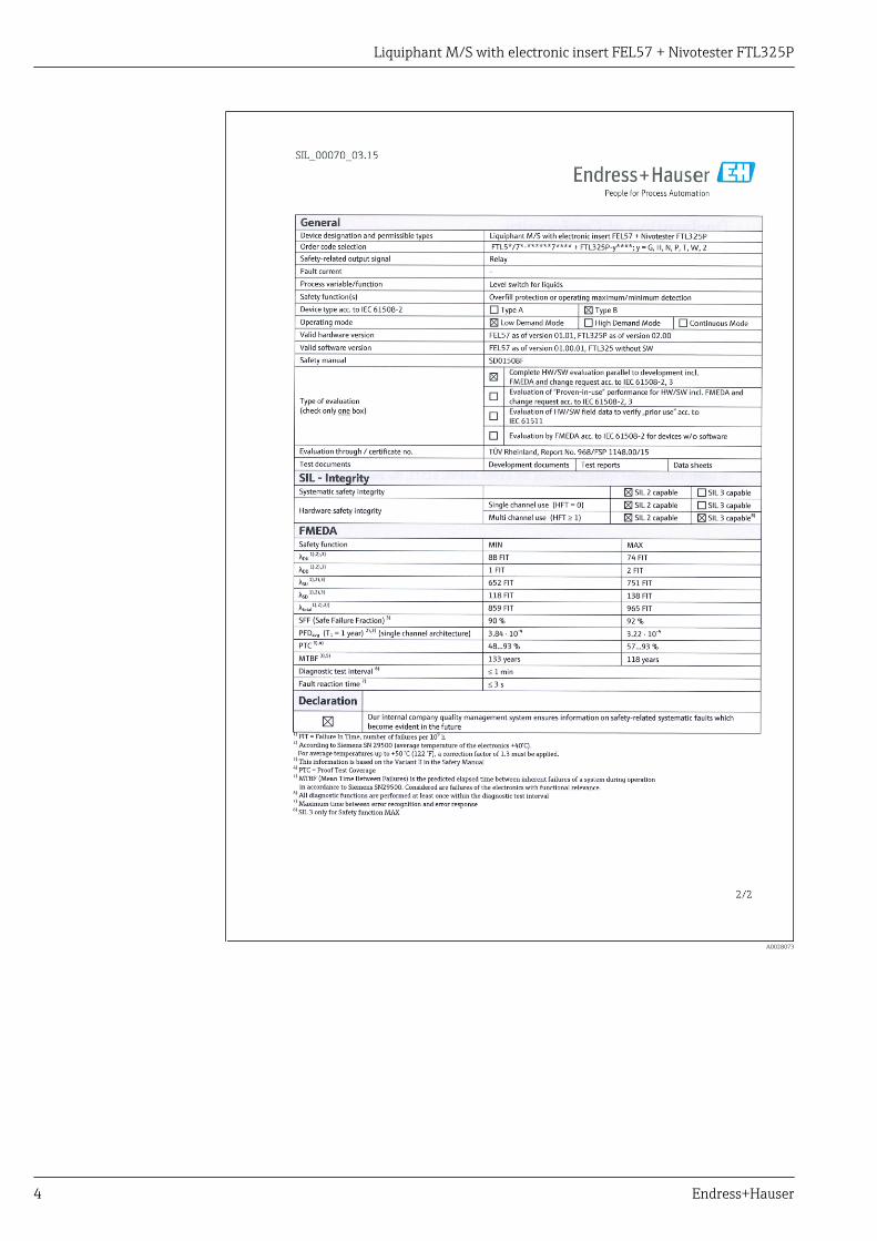
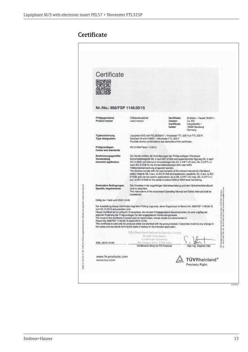
Certificate
A0028061
Liquiphant M/S with electronic insert FEL57 + Nivotester FTL325P
14 Endress+Hauser
Document information
Document function The document is part of the Operating Instructions and serves as a reference for application-specificparameters and notes.
• General information about functional safety: SIL• General information about SIL is available:
In the Download Area of the Endress+Hauser Internet site: www.de.endress.com/SIL
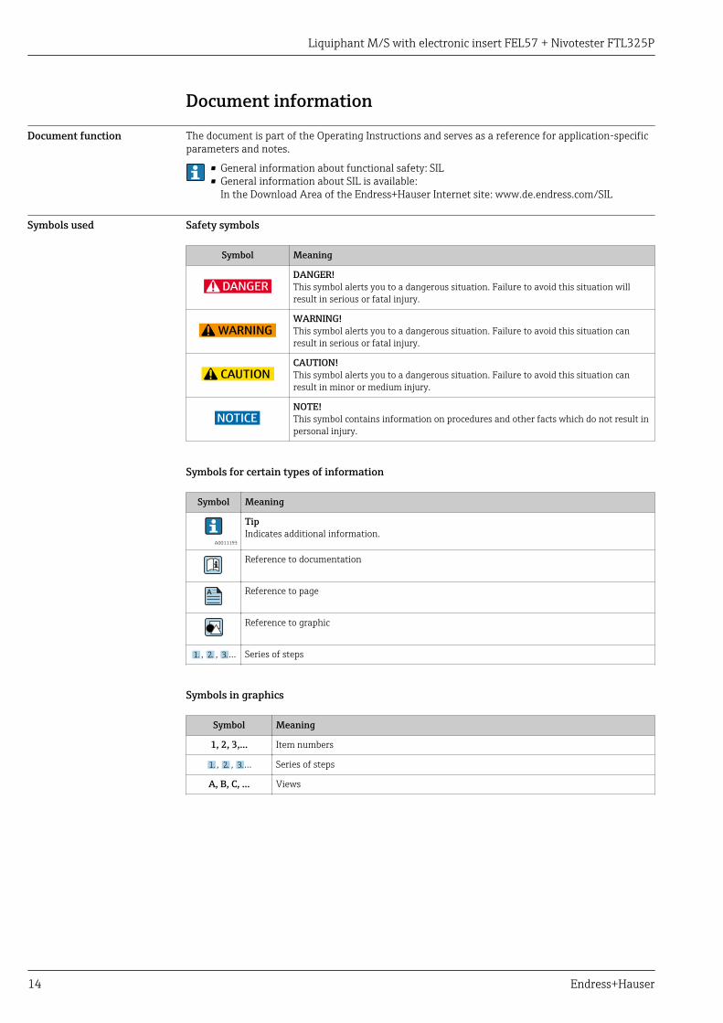
Symbols used Safety symbols
Symbol Meaning
DANGER
DANGER!This symbol alerts you to a dangerous situation. Failure to avoid this situation willresult in serious or fatal injury.
WARNING
WARNING!This symbol alerts you to a dangerous situation. Failure to avoid this situation canresult in serious or fatal injury.
CAUTION
CAUTION!This symbol alerts you to a dangerous situation. Failure to avoid this situation canresult in minor or medium injury.
NOTICE
NOTE!This symbol contains information on procedures and other facts which do not result inpersonal injury.
Symbols for certain types of information
Symbol Meaning
A0011193
TipIndicates additional information.
Reference to documentation
A Reference to page
Reference to graphic
1. , 2. , 3.… Series of steps
Symbols in graphics
Symbol Meaning
1, 2, 3,... Item numbers
1. , 2. , 3.… Series of steps
A, B, C, ... Views

Liquiphant M/S with electronic insert FEL57 + Nivotester FTL325P
Endress+Hauser 15
Supplementary devicedocumentation
Liquiphant M FTL50, FTL50H, FTL51, FTL51H, FTL51C
Documentation Comment
Technical Information:• TI00328F/00 (FTL50, FTL50H, FTL51, FTL51H)• TI00347F/00 (FTL51C)
The documentation is available on the Internet:→ www.endress.com
Operating Instructions:• KA00143F/00 (FTL50, FTL51)• KA00163F/00 (FTL50, FTL51 1))• KA00144F/00 (FTL50H, FTL51H)• KA00164F/00 (FTL50H, FTL51H 1))• KA00162F/00 (FTL51C)• KA00165F/00 (FTL51C 1))
• The document is provided with the device.• The documentation is available on the Internet:
→ www.endress.com
Safety instructions depending on the selected option"Approval".
Additional safety instructions (XA, ZE) are supplied withcertified device version.Please refer to the nameplate for the relevant safetyinstructions.
1) with T13 aluminum housing/separate connection compartment
Liquiphant S FTL70, FTL71
Documentation Comment
Technical Information:TI00354F/00
The documentation is available on the Internet:→ www.endress.com
Operating Instructions:• KA00172F/00• KA00173F/00 1)
• The document is provided with the device.• The documentation is available on the Internet:
→ www.endress.com
Safety instructions depending on the selected option"Approval".
Additional safety instructions (XA, ZE) are supplied withcertified device version.Please refer to the nameplate for the relevant safetyinstructions.
1) with T13 aluminum housing/separate connection compartment
Nivotester FTL325P
Documentation Comment
Technical Information:TI00350F/00
The documentation is available on the Internet:→ www.endress.com
Operating Instructions:• KA00167F/00 (1-channel)• KA00168F/00 (3-channel)
• The document is provided with the device.• The documentation is available on the Internet:
→ www.endress.com
Safety instructions depending on the selected option"Approval".
Additional safety instructions (XA, ZE) are supplied withcertified device version.Please refer to the nameplate for the relevant safetyinstructions.
This supplementary Safety Manual applies in addition to the Operating Instructions, TechnicalInformation and ATEX Safety Instructions. The supplementary device documentation must beobserved during installation, commissioning and operation. The requirements specific for theprotection function are described in this Safety Manual.

Liquiphant M/S with electronic insert FEL57 + Nivotester FTL325P
16 Endress+Hauser
Permitted devices typesThe details pertaining to functional safety in this manual relate to the device versions listed belowand are valid as of the specified firmware and hardware versions. Unless otherwise specified, all thefollowing versions can also be used for protective systems. A modification process according toIEC 61508 is applied for device changes.
Valid device versions for safety-related use: Liquiphant M FTL50, FTL50H, FTL51, FTL51H, FTL51C
Ordering feature Designation Option
010 Approval All
020 Process connection All
030 Probe length; type All
040 Electronics; output 7 FEL57; SIL 2-wire PFM
050 Housing; cable entry All
060 Additional options All
570 Service All
580 Test, certificate All
600 Sensor design All
895 Marking All
• Valid firmware version: 01.00.01 and higher• Valid hardware version: 01.01 and higher
Valid device versions for safety-related use: Liquiphant S FTL70, FTL71
Ordering feature Designation Option
010 Approval All
020 Process connection All
030 Probe length All
040 Electronics; output 7 FEL57; SIL 2-wire PFM
050 Housing; cable entry All
060 Additional options All
070 Application All
570 Service All
580 Test, certificate All
600 Sensor design All
895 Marking All
• Valid firmware version: 01.00.01 and higher• Valid hardware version: 01.01 and higher
Liquiphant M/S with electronic insert FEL57 + Nivotester FTL325P
Endress+Hauser 17
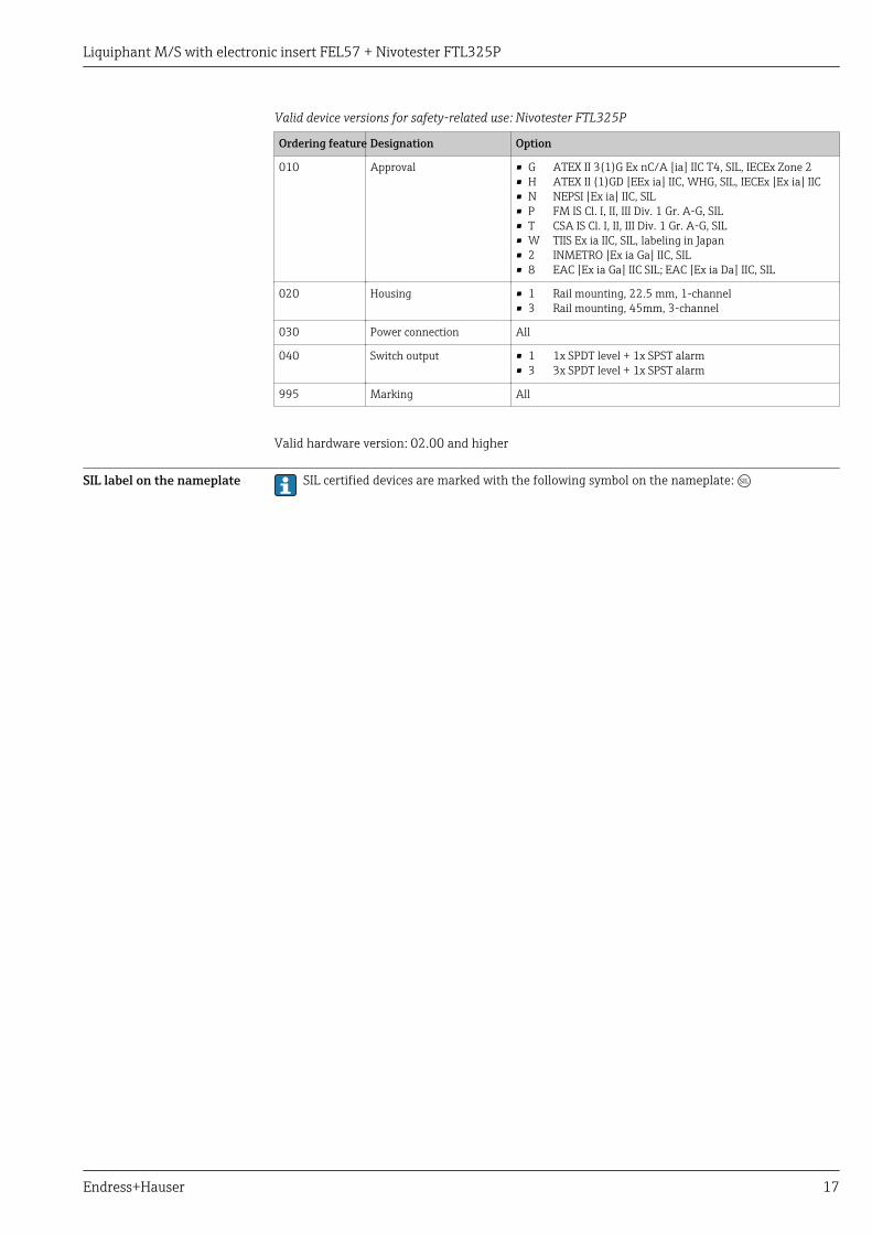
Valid device versions for safety-related use: Nivotester FTL325P
Ordering feature Designation Option
010 Approval • G• H• N• P• T• W• 2• 8
ATEX II 3(1)G Ex nC/A [ia] IIC T4, SIL, IECEx Zone 2ATEX II (1)GD [EEx ia] IIC, WHG, SIL, IECEx [Ex ia] IICNEPSI [Ex ia] IIC, SILFM IS Cl. I, II, III Div. 1 Gr. A-G, SILCSA IS Cl. I, II, III Div. 1 Gr. A-G, SILTIIS Ex ia IIC, SIL, labeling in JapanINMETRO [Ex ia Ga] IIC, SILEAC [Ex ia Ga] IIC SIL; EAC [Ex ia Da] IIC, SIL
020 Housing • 1• 3
Rail mounting, 22.5 mm, 1-channelRail mounting, 45mm, 3-channel
030 Power connection All
040 Switch output • 1• 3
1x SPDT level + 1x SPST alarm3x SPDT level + 1x SPST alarm
995 Marking All
Valid hardware version: 02.00 and higher
SIL label on the nameplate SIL certified devices are marked with the following symbol on the nameplate:
Liquiphant M/S with electronic insert FEL57 + Nivotester FTL325P
18 Endress+Hauser
Safety function
Definition of the safetyfunction
The measuring system's safety functions are:• Maximum point level monitoring (overfill protection)• Minimum point level monitoring (dry run protection)
For information on the choice of operating mode (MIN or MAX detection), see → 21.
Restrictions for use in safety-related applications
• The measuring system must be used correctly for the specific application, taken into account themedium properties and ambient conditions. Carefully follow instructions pertaining to criticalprocess situations and installation conditions from the Operating Instructions. The application-specific limits must be observed.
• The specifications from the Operating Instructions must not be exceeded, (→ 15).
Density of the medium
Operation is only permitted with liquids:• Depending on the configured density setting, the density of the liquid must be as follows:
– if the switch position is > 0.7 the density must be over 0.7 g/cm³ (common water- and oil-basedliquids).
– if the switch position is > 0.5 the density must be over 0.5 g/cm³ (e.g. liquefied gas, isopentane,petroleum ether).
• The gas phase above the liquid may not exceed a maximum permitted density value. Themaximum possible gas density depends on the temperature and the device.
LCAUTIONGas density is exceeded!"Free" state is not detected and "Covered" is always signaled.‣ The gas density may not be exceeded.

Liquiphant M/S with electronic insert FEL57 + Nivotester FTL325P
Endress+Hauser 19
1.000
0.100
0.010
ρ [g/cm³]
0.001+300
+527
-60
-76
+60
+140
+120
+248
+180
+356
+240
+464
±0
+32
[°C]T
[°F]
1.1
2.1
1.2
2.2
A0026840
1.1 Liquiphant M; density switch position 0.7 g/cm³1.2 Liquiphant S; density switch position 0.7 g/cm³2.1 Liquiphant M; density switch position 0.5 g/cm³2.2 Liquiphant S; density switch position 0.5 g/cm³
• There is no minimum density for the gas phase. Operation in a vacuum is permitted!• There is no maximum density for the liquid.• For more information on the levels of diagnostic coverage, refer to IEC 61508-2:2010
Appendix A.2, Comment 2 and Table A.1.
Buildup (only for minimum detection)
The device may only be used in media that do not tend to cause buildup. Buildup is considered to beany deposits with a thickness of over 0.5 mm (0.02 in). Buildup can have the effect that the demandmode of the safety function is not detected and the device will not switch as intended.
Buildup from 0.5 mm (0.02 in) is detected with low diagnostic coverage.
Solid particles - heterogeneous mixtures (only for minimum detection)
The medium may not contain solid particles with a diameter greater than 5 mm (0.2 in). Solidparticles lodged between the tines of the tuning fork can have the effect that the demand mode ofthe safety function is not detected and the device will not switch as intended.
Lodged solid particles are detected with low diagnostic coverage.
Hydrogen diffusion (only Liquiphant S - high temperature)
If there is a danger of hydrogen diffusion, the device may not be used if the following conditionsapply simultaneously. Hydrogen entering the device damages the sensor to the extent that thedemand mode of the safety function is not detected and the device does not switch as intended.• Not over +180 °C (+356 °F) and simultaneously• Not over 64 bar (928 psi)
The error is not detected by the diagnostics system.

Liquiphant M/S with electronic insert FEL57 + Nivotester FTL325P
20 Endress+Hauser
Wall distance
The distance between the tuning fork of the device and the wall of the vessel containing medium(e.g. tank, pipe) must be at least 10 mm (0.39 in).
Corrosion
The device may only be used in media to which the wetted parts used are resistant. Corrosion canhave the effect that the demand mode of the safety function is not detected and the device will notswitch as intended.
Corrosion is detected with low diagnostic coverage.
If coated sensors are used, measures must be taken to ensure there is no damage during installationand operation.
Abrasion
The device may not be used or cleaned in abrasive media. Material removal can have the effect thatthe demand mode is not detected.
Abrasion is detected with low diagnostic coverage.
Flow velocity
In the case of flowing media, the flow velocity in the area around the tuning fork may not exceed5 m/s. Higher flow velocities can have the effect that the demand mode is not detected and thesensor signals that it is free (uncovered).
External vibration
In systems exposed to strong external vibrations, e.g. in the 400 to 1 200 Hz range (accelerationspectral density >1 (m/s²)²/Hz) or ultrasound with cavitation, the safety function must be verified bysimulating a demand mode prior to operation. Accidental switchings may sporadically occur if astrong frequency from an external source is superimposed on the frequency of the tuning fork.
EMC compatibility
The device is certified in accordance with IEC 61326-3-2 and is therefore suitable for safety-related,industrial applications in a specified electromagnetic environment. If the specified electromagneticambient conditions are exceeded, the switch status might not be reliably detected. An unshieldedcable up to 1 000 m (3 281 ft) long can be used between the devices in these environmentalconditions. Electromagnetic interference immunity can be further improved by using shielded cables.
Mounting the Liquiphant M FTL51 with sliding sleeve
Particular care is required when mounting the device with a pipe extension in conjunction with asliding sleeve. The operator must implement appropriate measures is to ensure that the switch pointis not tampered with or that any tampering is reliably detected.
Liquiphant M/S with electronic insert FEL57 + Nivotester FTL325P
Endress+Hauser 21
Use in safety instrumented systems
Device behavior duringoperation
Behavior of device during power-up
The behavior of the device during power-up is described in the relevant Operating Instructions(→ 15).
Device behavior in safety function demand mode
The safety-related output signal consists of one switching contact per channel:Channel 1: terminal 4 and 5With the 3-channel Nivotester, also:• Channel 2: terminal 22 and 23• Channel 3: terminal 26 and 27
The switching contacts work with quiescent current safety; they are closed in the GOOD state.
The switching contacts are de-energized in the following situations:• In demand mode• If a fault is detected• If the supply voltage fails
Behavior of device in event of alarms and warnings
The behavior of the device if alarms or warnings occur is described in the relevant OperatingInstructions (→ 15).
Device configuration forsafety-related applications
The device configuration may not be changed if SIL operation is in progress.
Recommendation: perform a proof test after configuring to ensure that the safety function isworking correctly.
Configuring the Liquiphant
LCAUTIONThe permitted contact values of the relays may not be exceeded‣ The operator must take suitable measures to ensure that the permitted contact values of the
relays (U ≤ 253 VAC 50/60 Hz, I ≤ 2 A, P ≤ 500 VA at cos φ ≥ 0.7 or U ≤ 40 VDC, I ≤ 2 A, P ≤ 80W) are not exceeded (e.g. current limiter, fuse).
LCAUTIONThe protective function can be impaired‣ After commissioning the measuring system, changes to the settings can impact the protective
function.
Liquiphant M/S with electronic insert FEL57 + Nivotester FTL325P
22 Endress+Hauser
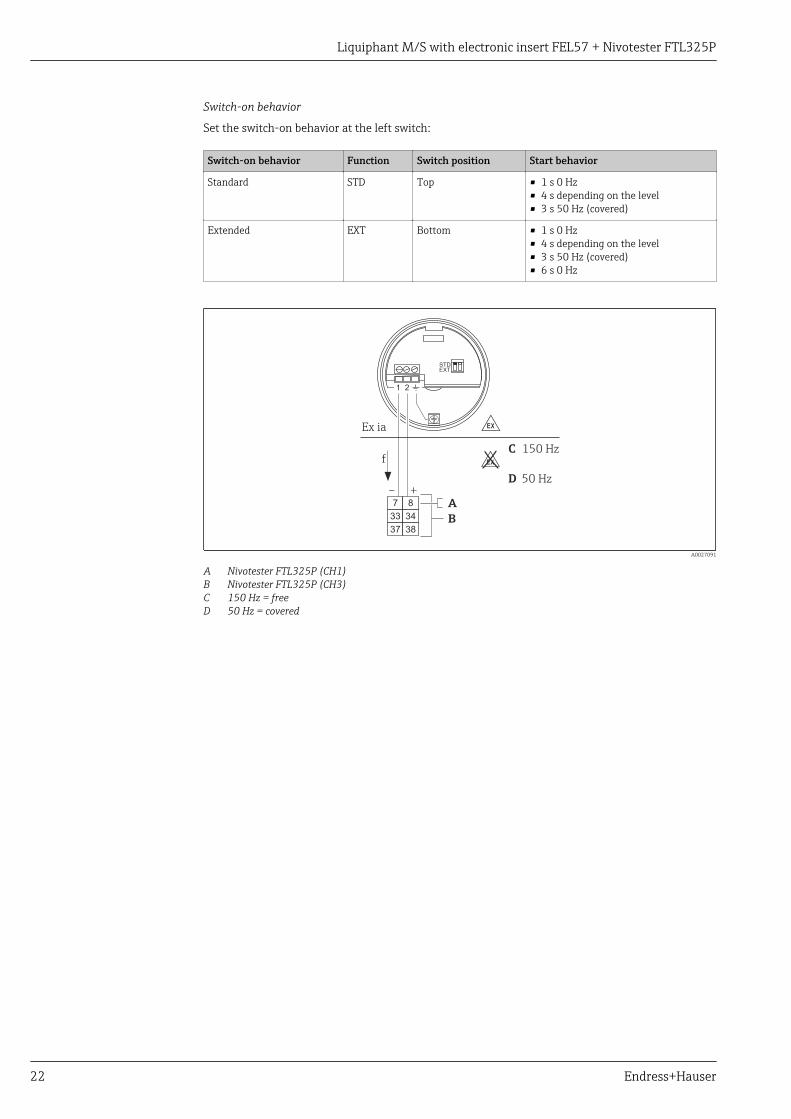
Switch-on behavior
Set the switch-on behavior at the left switch:
Switch-on behavior Function Switch position Start behavior
Standard STD Top • 1 s 0 Hz• 4 s depending on the level• 3 s 50 Hz (covered)
Extended EXT Bottom • 1 s 0 Hz• 4 s depending on the level• 3 s 50 Hz (covered)• 6 s 0 Hz
Ex ia
STDEXT
1 2
C 150 Hz
50 HzD
f
+–
7 8
33 34
37 38
A
B
-
.
A0027091
A Nivotester FTL325P (CH1)B Nivotester FTL325P (CH3)C 150 Hz = freeD 50 Hz = covered

Liquiphant M/S with electronic insert FEL57 + Nivotester FTL325P
Endress+Hauser 23
Density
Set the density at the right switch:
Liquid density Function Switch position Comment
>0.7 kg/dm³ >0.7 Top(See A in the graphic below)
Standard setting;Always use if possible
>0.5 kg/dm³ >0.5 Bottom(See B in the graphic below)
Special settings;Extremely light liquids (e.g.: liquefied natural gas)
U= 0 V
B
A
ρ
ρ
1
1
2
2
A0026156
A Standard setting (density >0.7 kg/dm³)A1 1 l (0.264 gal) or 1 dm³ (61.02 in³)A2 >0.7 kg (1.54 lbs)B Special setting (density >0.5 kg/dm³)B1 1 l (0.264 gal) or 1 dm³ (61.02 in³)B2 >0.5 to 0.7 kg (1.10 to 1.54 lbs)

Liquiphant M/S with electronic insert FEL57 + Nivotester FTL325P
24 Endress+Hauser
Configuring the Nivotester
Switch
Channel 1 Fault message Channel 2 1) Channel 3 1) MODE 1)
Mode of operation Version 1 2 2 1
MIN II MIN With Not applicable
III None MIN MIN 2
IV With 2
V 3
VI 1
MAX II MAX With Not applicable
III None MAX MAX 2
IV With 2
V 3
VI 1
1) Only for 3-channel Nivotester FTL325P
CH1
[Ex ia]
1 2
ON
1
1 2
ON
CH1
2
MA
XM
IN
A0026315
1 Operating and display element, 1-channel Nivotester FTL325P
1 DIL switch: MAX/MIN position (1), fault on/off position (2)2 Light emitting diodes (LEDs)

Liquiphant M/S with electronic insert FEL57 + Nivotester FTL325P
Endress+Hauser 25
1
2
3
4
ON
1 2
ON
CH1
CH2
[Ex ia]
1
3
1
2
3
4
ON
CH2CH2CH3CH3
2
1
MIN
MA
X
MIN
MA
X
1 2
ON
CH1
MA
XM
IN
2
5
1 2
3
4
ON
1
2
3
4
A0026422
2 Operating and display element, 3-channel Nivotester FTL325P
1 DIL switch: MAX/MIN position (1), fault on/off position (2)2 Light emitting diodes (LEDs)3 DIL switch: MAX/MIN position4 Switch for functions: Δs, e.g. pump control (1), two level relays (2), individual channels (3)5 Light emitting diodes (LEDs)
Proof-testing Check the operativeness and safety of safety functions at appropriate intervals! The operator mustdetermine the time intervals.
The values and figures in the "Additional safety-related characteristic values" section can be used tothis end, → 5. The check must be carried out in such a way that it is proven that the protectivesystem functions perfectly in interaction with all components.
Proof-testing can be performed as follows:• Test sequence A:
Approach the level or remove and immerse in a medium of similar density and viscosity.• Test sequence B:
Activate simulation by pressing the test button on the Nivotester.• Test sequence C
Check the switch point under reference operating conditions
NOTICEEnsuring correct device sealing!‣ You must also check and ensure that all cover seals and cable entries are sealing correctly.
Liquiphant M/S with electronic insert FEL57 + Nivotester FTL325P
26 Endress+Hauser
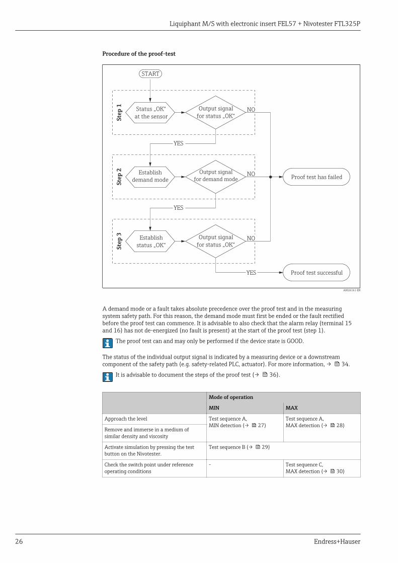
Procedure of the proof-test
START
YES
YES
YES
NO
NO
NO
Proof test has failed
Proof test successful
Output signal
for status „OK“
Output signal
for demand mode
Output signal
for status „OK“
Ste
p 1
Ste
p 2
Ste
p 3
Status „OK“
at the sensor
Establish
demand mode
Establish
status „OK“
A0026161-EN
A demand mode or a fault takes absolute precedence over the proof test and in the measuringsystem safety path. For this reason, the demand mode must first be ended or the fault rectifiedbefore the proof test can commence. It is advisable to also check that the alarm relay (terminal 15and 16) has not de-energized (no fault is present) at the start of the proof test (step 1).
The proof test can and may only be performed if the device state is GOOD.
The status of the individual output signal is indicated by a measuring device or a downstreamcomponent of the safety path (e.g. safety-related PLC, actuator). For more information, → 34.
It is advisable to document the steps of the proof test (→ 36).
Mode of operation
MIN MAX
Approach the level Test sequence A,MIN detection (→ 27)
Test sequence A,MAX detection (→ 28)
Remove and immerse in a medium ofsimilar density and viscosity
Activate simulation by pressing the testbutton on the Nivotester.
Test sequence B (→ 29)
Check the switch point under referenceoperating conditions
- Test sequence C,MAX detection (→ 30)

Liquiphant M/S with electronic insert FEL57 + Nivotester FTL325P
Endress+Hauser 27
test sequence A, MIN detection
• Approach the level or• Remove and immerse in a medium of similar density and viscosity
Step 11. Raise the level or immerse the tuning fork of the sensor that has been removed into the
medium until the tuning fork is fully covered. If it is not possible to do this with the original medium, a medium of a similar density and
viscosity must be used.2. Check the status of the safety contacts.
Version
Terminal II III IV V VI
4+5 Closed Not applicable Closed Closed Closed
22+23 Not applicable Closed Closed Closed Not applicable
26+27 Not applicable Closed Closed Closed Not applicable
If one or more safety contacts are open, a fault has occurred in the safety path. The proof testhas not been passed and must be aborted.
Step 21. Lower the level or remove the tuning fork of the sensor that has been removed out of the
medium until the tuning fork is completely free.2. After immersing the fork (plus a response time of approx. 2 s), check the status of the safety
contacts.
Version
Terminal II III IV V VI
4+5 Open Not applicable Open Open Open
22+23 Not applicable Open Open Open Not applicable
26+27 Not applicable Open Open Open Not applicable
If one or more safety contacts are closed, a fault has occurred in the safety path. The proof testhas not been passed and must be aborted.
Step 31. Re-install the sensor that was removed.2. Restore the GOOD state by fully covering the tuning fork.3. After immersing the fork (plus a response time of approx. 1 s), after the voltage is restored as
part of standard switch-on behavior (→ 22) (plus a response time of approx. 9 s) or afterthe voltage is restored as part of extended switch-on behavior (→ 22) (plus a response timeof approx. 45 s), check the status of the safety contacts.
Version
Terminal II III IV V VI
4+5 Closed Not applicable Closed Closed Closed
22+23 Not applicable Closed Closed Closed Not applicable
26+27 Not applicable Closed Closed Closed Not applicable
If one or more safety contacts are open, a fault has occurred in the safety path. The proof testhas not been passed and must be aborted.
Liquiphant M/S with electronic insert FEL57 + Nivotester FTL325P
28 Endress+Hauser
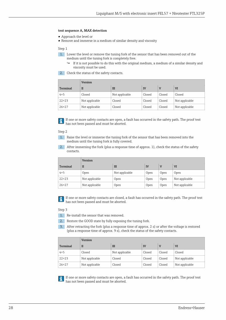
test sequence A, MAX detection
• Approach the level or• Remove and immerse in a medium of similar density and viscosity
Step 11. Lower the level or remove the tuning fork of the sensor that has been removed out of the
medium until the tuning fork is completely free. If it is not possible to do this with the original medium, a medium of a similar density and
viscosity must be used.2. Check the status of the safety contacts.
Version
Terminal II III IV V VI
4+5 Closed Not applicable Closed Closed Closed
22+23 Not applicable Closed Closed Closed Not applicable
26+27 Not applicable Closed Closed Closed Not applicable
If one or more safety contacts are open, a fault has occurred in the safety path. The proof testhas not been passed and must be aborted.
Step 21. Raise the level or immerse the tuning fork of the sensor that has been removed into the
medium until the tuning fork is fully covered.2. After immersing the fork (plus a response time of approx. 1), check the status of the safety
contacts.
Version
Terminal II III IV V VI
4+5 Open Not applicable Open Open Open
22+23 Not applicable Open Open Open Not applicable
26+27 Not applicable Open Open Open Not applicable
If one or more safety contacts are closed, a fault has occurred in the safety path. The proof testhas not been passed and must be aborted.
Step 31. Re-install the sensor that was removed.2. Restore the GOOD state by fully exposing the tuning fork.3. After retracting the fork (plus a response time of approx. 2 s) or after the voltage is restored
(plus a response time of approx. 9 s), check the status of the safety contacts.
Version
Terminal II III IV V VI
4+5 Closed Not applicable Closed Closed Closed
22+23 Not applicable Closed Closed Closed Not applicable
26+27 Not applicable Closed Closed Closed Not applicable
If one or more safety contacts are open, a fault has occurred in the safety path. The proof testhas not been passed and must be aborted.

Liquiphant M/S with electronic insert FEL57 + Nivotester FTL325P
Endress+Hauser 29
test sequence B
Activate simulation by pressing the test button on the Nivotester.
Step 1
‣ Check the status of the safety contacts.
Version
Terminal II III IV V VI
4+5 Closed Not applicable Closed Closed Closed
22+23 Not applicable Closed Closed Closed Not applicable
26+27 Not applicable Closed Closed Closed Not applicable
If one or more safety contacts are open, a fault has occurred in the safety path. The proof testhas not been passed and must be aborted.
Step 21. Press and hold the test button on the Nivotester.2. Check the status of the safety contacts.
Version
Terminal II III IV V VI
4+5 Open Not applicable Open Open Open
22+23 Not applicable Open Open Open Not applicable
26+27 Not applicable Open Open Open Not applicable
If one or more safety contacts are closed, a fault has occurred in the safety path. The proof testhas not been passed and must be aborted.
Step 31. Release the test button on the Nivotester.2. After releasing the button (plus a response time of approx. 9 s), check the status of the safety
contacts.
Version
Terminal II III IV V VI
4+5 Closed Not applicable Closed Closed Closed
22+23 Not applicable Closed Closed Closed Not applicable
26+27 Not applicable Closed Closed Closed Not applicable
If one or more safety contacts are open, a fault has occurred in the safety path. The proof testhas not been passed and must be aborted.
Liquiphant M/S with electronic insert FEL57 + Nivotester FTL325P
30 Endress+Hauser
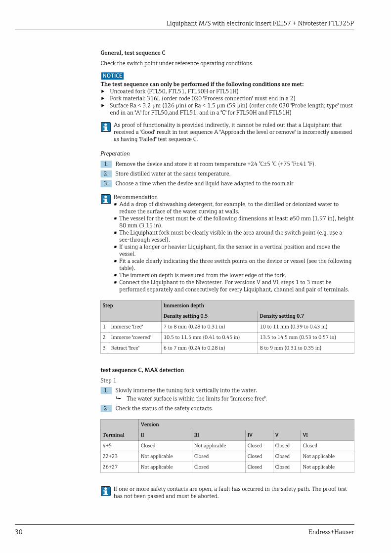
General, test sequence C
Check the switch point under reference operating conditions.
NOTICEThe test sequence can only be performed if the following conditions are met:‣ Uncoated fork (FTL50, FTL51, FTL50H or FTL51H)‣ Fork material: 316L (order code 020 "Process connection" must end in a 2)‣ Surface Ra < 3.2 µm (126 µin) or Ra < 1.5 µm (59 µin) (order code 030 "Probe length; type" must
end in an "A" for FTL50,and FTL51, and in a "C" for FTL50H and FTL51H)
As proof of functionality is provided indirectly, it cannot be ruled out that a Liquiphant thatreceived a "Good" result in test sequence A "Approach the level or remove" is incorrectly assessedas having "Failed" test sequence C.
Preparation
1. Remove the device and store it at room temperature +24 °C±5 °C (+75 °F±41 °F).2. Store distilled water at the same temperature.3. Choose a time when the device and liquid have adapted to the room air
Recommendation• Add a drop of dishwashing detergent, for example, to the distilled or deionized water to
reduce the surface of the water curving at walls.• The vessel for the test must be of the following dimensions at least: ø50 mm (1.97 in), height
80 mm (3.15 in).• The Liquiphant fork must be clearly visible in the area around the switch point (e.g. use a
see-through vessel).• If using a longer or heavier Liquiphant, fix the sensor in a vertical position and move the
vessel.• Fit a scale clearly indicating the three switch points on the device or vessel (see the following
table).• The immersion depth is measured from the lower edge of the fork.• Connect the Liquiphant to the Nivotester. For versions V and VI, steps 1 to 3 must be
performed separately and consecutively for every Liquiphant, channel and pair of terminals.
Step Immersion depth
Density setting 0.5 Density setting 0.7
1 Immerse "free" 7 to 8 mm (0.28 to 0.31 in) 10 to 11 mm (0.39 to 0.43 in)
2 Immerse "covered" 10.5 to 11.5 mm (0.41 to 0.45 in) 13.5 to 14.5 mm (0.53 to 0.57 in)
3 Retract "free" 6 to 7 mm (0.24 to 0.28 in) 8 to 9 mm (0.31 to 0.35 in)
test sequence C, MAX detection
Step 11. Slowly immerse the tuning fork vertically into the water.
The water surface is within the limits for "Immerse free".2. Check the status of the safety contacts.
Version
Terminal II III IV V VI
4+5 Closed Not applicable Closed Closed Closed
22+23 Not applicable Closed Closed Closed Not applicable
26+27 Not applicable Closed Closed Closed Not applicable
If one or more safety contacts are open, a fault has occurred in the safety path. The proof testhas not been passed and must be aborted.

Liquiphant M/S with electronic insert FEL57 + Nivotester FTL325P
Endress+Hauser 31
Step 21. Slowly further immerse the tuning fork vertically into the water.
The water surface is within the limits for "Immerse covered".2. After immersing the fork (plus a response time of approx. 1 s), check the status of the safety
contacts.
Version
Terminal II III IV V VI
4+5 Open Not applicable Open Open Open
22+23 Not applicable Open Open Open Not applicable
26+27 Not applicable Open Open Open Not applicable
If one or more safety contacts are open, a fault has occurred in the safety path. The proof testhas not been passed and must be aborted.
Step 31. Slowly retract the tuning fork vertically from the water.
The water surface is within the limits for "Retract free".2. After retracting the fork (plus a response time of approx. 1 s), check the status of the safety
contacts.
Version
Terminal II III IV V VI
4+5 Closed Not applicable Closed Closed Closed
22+23 Not applicable Closed Closed Closed Not applicable
26+27 Not applicable Closed Closed Closed Not applicable
If one or more safety contacts are open, a fault has occurred in the safety path. The proof testhas not been passed and must be aborted.

Liquiphant M/S with electronic insert FEL57 + Nivotester FTL325P
32 Endress+Hauser
Life cycle
Requirements for personnel The personnel for installation, commissioning, diagnostics, repair and maintenance must meet thefollowing requirements:• Trained, qualified specialists must have a relevant qualification for this specific function and task• Are authorized by the plant owner/operator• Are familiar with federal/national regulations• Before beginning work, the specialist staff must have read and understood the instructions in the
manuals and supplementary documentation as well as in the certificates (depending on theapplication)
• Follow instructions and comply with basic conditionsThe operating personnel must meet the following requirements:• Are instructed and authorized according to the requirements of the task by the facility's owner-
operator• Follow the instructions in this manual
Installation The installation of the device is described in the relevant Operating Instructions (→ 15).
As the application conditions affect the reliability of the measurement, please pay attention to thenotes in the Technical information and Operating Instructions (→ 15).
Operation Mandatory settings and information for the safety function (→ 21).
Maintenance Maintenance information, .
Alternative monitoring measures must be taken to ensure process safety during configuration,proof-testing and maintenance work on the device.
Repair Repair means a one-to-one replacement of components. Repairs on the devices must always becarried out by Endress+Hauser. Safety functions cannot be guaranteed if repairs are carried outby anybody else.
Exceptions:
Qualified personnel may replace the following components on the condition that original spare partsare used and the relevant Installation Instructions are observed:
Component Installation Instructions Checking the device after repair
Electronic insert EA01030F/00 Proof-testing, see the "Proof-testing" section(→ 25) 1)
Housing cover T13 • EA01049F/00 (electronics)• EA01049F/00 (inspection
glass)• EA01050F/00 (connection)
Housing cover F13 EA01046F/00
Housing cover F15 EA01034F/00
Housing cover F16 EA01035F/00
Housing cover F17 EA01036F/00
Housing cover F27 EA01047F/00
Cover seal F15 KA00620F/00
1) Additional country-specific regulations and tests must be observed.
In the event of failure of a SIL-labeled Endress+Hauser device, which has been operated in aprotection function, the "Declaration of Contamination and Cleaning" with the corresponding note"Used as SIL device in protective system" must be enclosed when the defective device is returned.Please refer to the "Return" section of the relevant Operating Instructions → 15.

Liquiphant M/S with electronic insert FEL57 + Nivotester FTL325P
Endress+Hauser 33
Modification Modifications are changes to devices with SIL capability already delivered or installed.
Modifications to devices with SIL capability are usually performed in the Endress+Hausermanufacturing center.
Modifications to devices with SIL capability onsite at the user's plant are possible following approvalby the Endress+Hauser manufacturing center. In this case, the modifications must be performed anddocumented by an Endress+Hauser service technician.
Modifications to devices with SIL capability by the user are not permitted.
Decommissioning For detailed information on decommissioning, see the relevant Operating Instructions → 15

Liquiphant M/S with electronic insert FEL57 + Nivotester FTL325P
34 Endress+Hauser
Appendix
Structure of the measuringsystem
System components
The measuring system's devices are displayed in the following diagram (example):
CH1
CH1
[Ex ia]
CH1
CH2
CH2
CH3
CH3
[Ex ia]
1 2 3
A0025771
1 Liquiphant M/S2 1-channel Nivotester FTL325P3 3-channel Nivotester FTL325P
Description of use as a protective system
The sensor's tuning fork vibrates at its intrinsic frequency. The vibration frequency decreases as thedensity increases. This change in the frequency causes the current signal to change. There is a choiceof two operating modes:• Minimum detection• Maximum detection
MIN detection
The measuring system is used to protect against a level that is too low (e.g. pump dry runningprotection, protection against emptying or protection against insufficient filling).
In normal operation, the tuning fork is covered by liquid and the measuring system reports the"GOOD" state. If the tuning fork is free, the device assumes the safe state and signals thedemand mode.
MAX detection
The measuring system is used to protect against a level that is too high (e.g. overfill prevention).
In normal operation, the tuning fork is not covered by liquid and the measuring system reportsthe "GOOD" state. If the tuning fork is covered, the device assumes the safe state and signals thedemand mode.
The switch point depends on the installation. It is in the area of the tuning fork, see the followingdiagram.

Liquiphant M/S with electronic insert FEL57 + Nivotester FTL325P
Endress+Hauser 35
A B C
38
(1
.5)
38
(1
.5)
18
(0
.71
)
18
(0
.71
)
7 (
0.2
8)
7 (
0.2
8)
A0026065
3 Dimensions: mm (in)
A Installation from aboveB Installation from belowC Installation from the side
For information about the switch point under reference operating conditions, please refer to theTechnical Information, → 15.
Correct installation is a prerequisite for safe operation of the device.

Liquiphant M/S with electronic insert FEL57 + Nivotester FTL325P
36 Endress+Hauser
Commissioning orproof test report
Report
System-specific data
Company
Measuring point/TAG no.
Facility
Device type/Order code
Serial no. Liquiphant(en)
Serial no. Nivotester
Name
Date
Signature
Operating mode, density range and version (please tick appropriate box)
Mode of operation MIN safety
MAX safety
Density switch Setting >0.7
Setting >0.5
Version II One Liquiphant on one channel (1oo1)
III One Liquiphant (1oo1), output relay CH2 and CH3 switched in series (1oo2)
IV Two Liquiphant devices (1oo2), output relay CH1, CH2 and CH3 switched in series(1oo3)
V Three Liquiphant devices, evaluation e.g., by PLC (2oo3)
VI Three Liquiphant devices, 1 x SIL, 2 x level control (∆s)
Commissioning or proof test report
Test sequence A Approach the level
Remove and immerse in a medium of similar density and viscosity
B Perform simulation on Liquiphant by pressing test button 1)
Perform simulation on Nivotester by pressing test button
C Check the switch point under reference operating conditions. 2).
Version
Test step Terminal
II III IV V VI Actual value
Step 1 4+5 3)
(GOOD state) 22+23 3) 4)
Switch is closed 26+27 3) 4)
Step 2 4+5 3)
(demand mode) 22+23 3) 4)
Switch is open 26+27 3) 4)
Step 3 4+5 3)
(GOOD state) 22+23 3) 4)
Switch is closed 26+27 3) 4)
Liquiphant M/S with electronic insert FEL57 + Nivotester FTL325P
Endress+Hauser 37
System-specific data
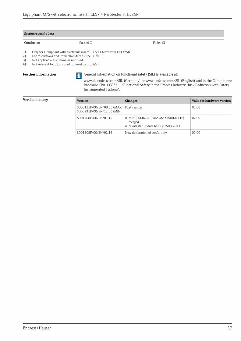
Conclusion Passed Failed
1) Only for Liquiphant with electronic insert FEL58 + Nivotester FLT325N.2) For restrictions and immersion depths, see → 303) Not applicable as channel is not used.4) Not relevant for SIL, is used for level control (∆s).
Further information General information on functional safety (SIL) is available at:
www.de.endress.com/SIL (Germany) or www.endress.com/SIL (English) and in the CompetenceBrochure CP01008Z/11 "Functional Safety in the Process Industry- Risk Reduction with SafetyInstrumented Systems".
Version history Version Changes Valid for hardware version
SD00111F/00/EN/08.06 (MAX)SD00231F/00/EN/12.06 (MIN)
First version 01.00
SD01508F/00/EN/01.15 • MIN (SD00231F) and MAX (SD00111F)merged
• Nivotester Update to IEC61508-2011
02.00
SD01508F/00/EN/02.16 New declaration of conformity 02.00


www.addresses.endress.com
*71386529*71386529