
INSERT MODEL IMAGE
29
JCB ELECTRIC COMPACT EXCAVATOR 19C-1E Quick Start Guide INSERT MODEL IMAGE
-
Upload
khangminh22 -
Category
Documents
-
view
3 -
download
0
Transcript of INSERT MODEL IMAGE

JCB ELECTRIC COMPACT EXCAVATOR19C-1E
Quick Start Guide
INSERT MODEL IMAGE

2
DISCLAIMER
19C-1E
This Quick Reference Guide is to provide quick and simple information to the Operator and does not include any health and safety aspects. In addition, because of our continual development of machines, features described in this Quick Reference Guide may differ from those on your machine. No errors and omissions can be entirely ruled out.
This Quick Reference Guide DOES NOT replace the Operators Manual. You MUST read ALL the disclaimers and safety and other instructions in the Operators Manual before initially operating this product. Accordingly, no legal claims can be entertained on the basis of the data, illustrations or descriptions in this Quick Reference Guide.
This machine should not be operated by any person who isn’t appropriately qualified or had the appropriate training.
Operation of this machine without periodic maintenance could cause it to malfunction. For more information please contact your JCB Dealer.
WARNING: This machine uses a 48V electrical powertrain system. DO NOT work on this machine unless you are suitably trained, competent and authorised to carry out work in a safe and controlled manner.
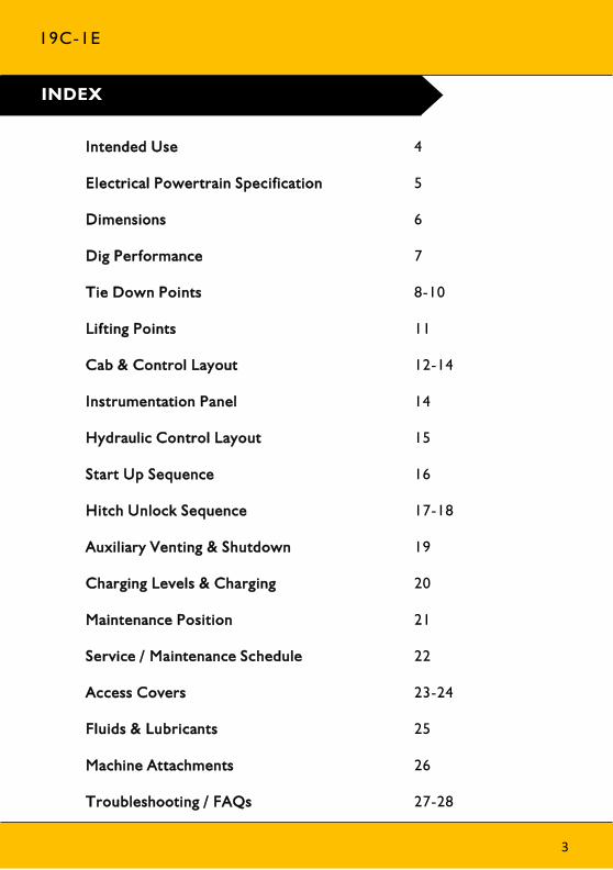
INDEX
19C-1E
Intended Use
Electrical Powertrain Specification
Dimensions
Dig Performance
Tie Down Points
Lifting Points
Cab & Control Layout
Instrumentation Panel
Hydraulic Control Layout
Start Up Sequence
Hitch Unlock Sequence
Auxiliary Venting & Shutdown
Charging Levels & Charging
Maintenance Position
Service / Maintenance Schedule
Access Covers
Fluids & Lubricants
Machine Attachments
Troubleshooting / FAQs
4
5
6
7
8-10
11
12-14
14
15
16
17-18
19
20
21
22
23-24
25
26
27-28
3

General
• Machine Type – Compact Excavator
• Self propelled machine with a tracked undercarriage
• 360° revolving upper structure with boom, dipper, bucket and slew mechanism
Intended Use
• Machine intended to be used in normal conditions as detailed in the operators manual
• With bucket fitted, machine work cycle consists of digging, elevating, slewing and discharging of materials
• Applications include earthmoving, road construction, building and construction, landscaping and indoor areas etc.
• Can be used for object handling if fitted with relevant parts and systems
• Not intended for use in mining and quarrying applications, demolition, forestry and any explosive atmospheres
• Must not be used for forestry, used with attachments of unknown weight, used on surfaces with unknown stability – list not exhaustive
• PPE may be required in certain applications/environments e.g. high silica concentration or asbestos
• The machine should not be operated by any person without appropriate qualifications, training or experience of using this type of machine
• Prior to use, the machines suitability should be considered with regards to the intended applications and any hazards which may be present
INTENDED USE
19C-1E
4
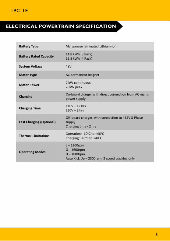
ELECTRICAL POWERTRAIN SPECIFICATION
19C-1E
5
Battery Type Manganese laminated Lithium-ion
Battery Rated Capacity14.8 kWh (3 Pack)19.8 kWh (4 Pack)
System Voltage 48V
Motor Type AC permanent magnet
Motor Power7 kW continuous20kW peak
ChargingOn-board charger with direct connection from AC mains power supply
Charging Time110V – 12 hrs230V – 8 hrs
Fast Charging (Optional)Off-board charger, with connection to 415V 3-Phase supplyCharging time <2 hrs
Thermal LimitationsOperation: -10oC to +46oCCharging: -10oC to +40oC
Operating Modes
L – 1200rpmG – 1600rpmH – 1800rpmAuto Kick Up – 2300rpm, 2 speed tracking only

Please see operator manual for full details.
Description 19C-1E
A Sprocket idler centres mm 1218
B Track length on ground mm 1220
C Undercarriage overall length – rubber mm 1578
Undercarriage overall length – steel mm 1578
D Kingpost clearance mm 409
E Tail swing radius mm 1103
F Overall width of superstructure mm 996
G Height over cab mm 2324
H Ground clearance mm 162
J Track gauge – Retracted mm 750
Track gauge – Extended mm 1110
K Width over tracks – Retracted mm 980
Width over tracks – Extended mm 1330
L Transport length- 950mm dipper mm 3860
Transport length – 1,100mm dipper mm 3862
Transport length – 1,344mm dipper mm 3815
M Track height mm 367
N Counterweight clearance mm 434
Operating weight* kg 1862
* Standard machine specification, please see data plate for specific machine weight
19C-1E
DIMENSIONS
Fig.1
6
Please see operator manual for full details.
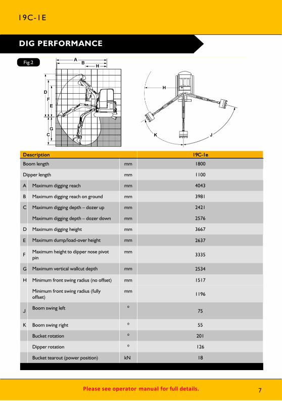
Description 19C-1e
Boom length mm 1800
Dipper length mm 1100
A Maximum digging reach mm 4043
B Maximum digging reach on ground mm 3981
C Maximum digging depth – dozer up mm 2421
Maximum digging depth – dozer down mm 2576
D Maximum digging height mm 3667
E Maximum dump/load-over height mm 2637
F Maximum height to dipper nose pivot pin
mm 3335
G Maximum vertical wallcut depth mm 2534
H Minimum front swing radius (no offset) mm 1517
Minimum front swing radius (fully offset)
mm1196
JBoom swing left ⁰
75
K Boom swing right ⁰ 55
Bucket rotation ⁰ 201
Dipper rotation ⁰ 126
Bucket tearout (power position) kN 18
19C-1E
DIG PERFORMANCE
Fig.2
7
Please see operator manual for full details.
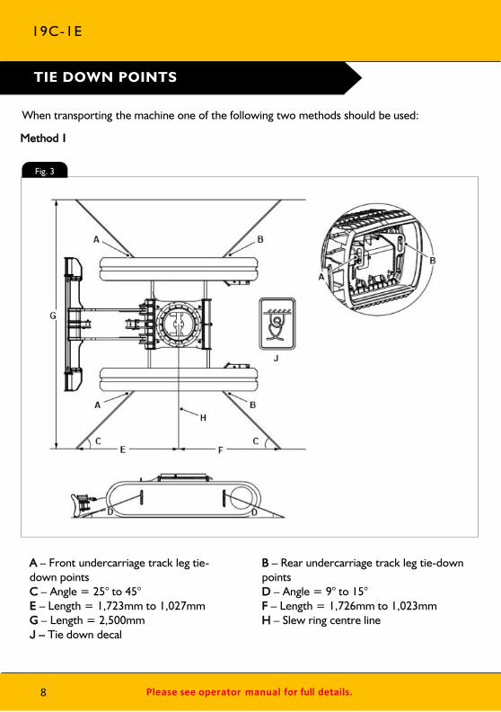
TIE DOWN POINTS
When transporting the machine one of the following two methods should be used:
Method 1
A – Front undercarriage track leg tie-down pointsC – Angle = 25° to 45°E – Length = 1,723mm to 1,027mmG – Length = 2,500mmJ – Tie down decal
B – Rear undercarriage track leg tie-down pointsD – Angle = 9° to 15°F – Length = 1,726mm to 1,023mmH – Slew ring centre line
19C-1E
Fig. 3
8

Please see operator manual for full details. 9
TIE DOWN POINTS
Method 2
A – Front slew spine tie-down pointC – Angle = 35° to 46°E – Angle = 9° to 15°G – Length = 2,720mm to 1,943mmJ – Slew ring centre line
B – Rear slew spine tie-down pointD – Angle = 45° to 50°F – Length = 2,499mm to 1,846mmH – Length = 2,500mmK – Tie down decal
19C-1E
Fig. 4
Please see operator manual for full details.
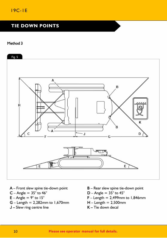
TIE DOWN POINTS
Method 3
A – Front slew spine tie-down pointC – Angle = 35° to 46°E – Angle = 9° to 15°G – Length = 2,282mm to 1,670mmJ – Slew ring centre line
B – Rear slew spine tie-down pointD – Angle = 35° to 45°F – Length = 2,499mm to 1,846mmH – Length = 2,500mmK – Tie down decal
19C-1E
Fig. 5
10
Please see operator manual for full details.
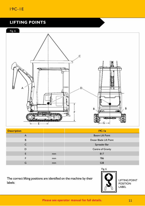
Description 19C-1e
A Boom Lift Point
B Dozer Blade Lift Point
C Spreader Bar
D Centre of Gravity
E mm 817
F mm 786
G mm 528
The correct lifting positions are identified on the machine by their labels:
Fig. 6
LIFTING POINTPOSITION LABEL
LIFTING POINTS
19C-1E
vA
E
F
D
C
G
B B
Fig. 6
11
Please see operator manual for full details.
CAB & SWITCH PANEL
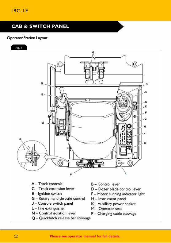
A – Track controlsC – Track extension leverE – Ignition switchG – Rotary hand throttle controlJ – Console switch panelL – Fire extinguisherN – Control isolation leverQ – Quickhitch release bar stowage
Operator Station Layout
19C-1E
B – Control leverD – Dozer blade control leverF – Motor running indicator lightH – Instrument panelK – Auxiliary power socketM – Operator seatP – Charging cable stowage
Fig. 7
12
Please see operator manual for full details.
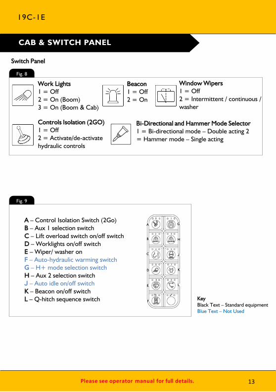
KeyBlack Text – Standard equipmentBlue Text – Not Used
CAB & SWITCH PANEL
19C-1E
A – Control Isolation Switch (2Go)B – Aux 1 selection switchC – Lift overload switch on/off switchD – Worklights on/off switchE – Wiper/ washer onF – Auto-hydraulic warming switchG – H+ mode selection switchH – Aux 2 selection switchJ – Auto idle on/off switchK – Beacon on/off switchL – Q-hitch sequence switch
A
B
C
D
E
F
G
H
J
K
L
Work Lights1 = Off2 = On (Boom) 3 = On (Boom & Cab)
Beacon1 = Off2 = On
Controls Isolation (2GO)1 = Off2 = Activate/de-activate hydraulic controls
Window Wipers1 = Off2 = Intermittent / continuous / washer
Bi-Directional and Hammer Mode Selector1 = Bi-directional mode – Double acting 2 = Hammer mode – Single acting
Switch Panel
Fig. 9
Fig. 8
13
Please see operator manual for full details.
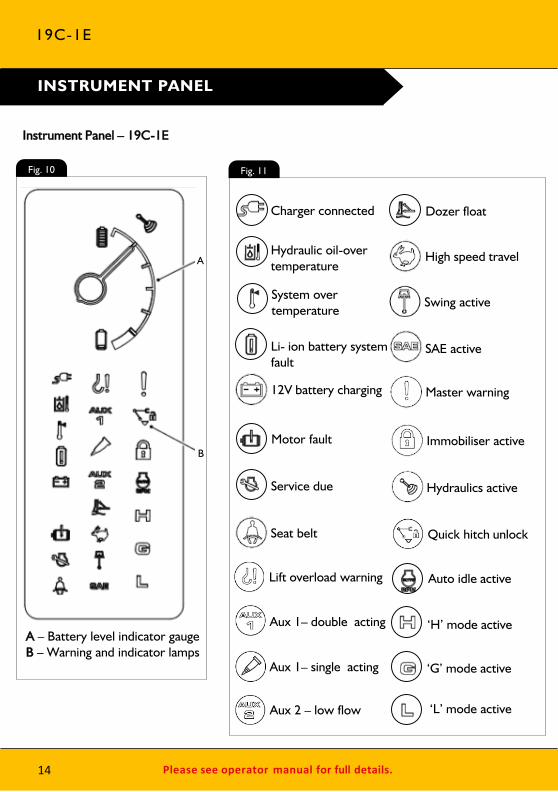
INSTRUMENT PANEL
A – Battery level indicator gaugeB – Warning and indicator lamps
Master warning
Immobiliser active
Hydraulics active
Lift overload warning
12V battery charging
Quick hitch unlockSeat belt
High speed travel
SAE active
Aux 1– double acting
Aux 2 – low flow
Aux 1– single acting
Swing active
Instrument Panel – 19C-1E
19C-1E
14
A
B
Charger connected
Hydraulic oil-over temperature
System over temperature
Li- ion battery system fault
Motor fault
Service due
Dozer float
Auto idle active
‘H’ mode active
‘G’ mode active
‘L’ mode active
Fig. 11Fig. 10
Please see operator manual for full details.
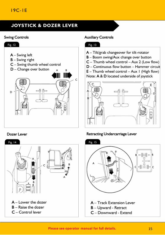
A – Tilt/grab changeover for tilt-rotator B – Boom swing/Aux change over buttonC – Thumb wheel control – Aux 2 (Low flow)D – Continuous flow button – Hammer circuit E – Thumb wheel control – Aux 1 (High flow)Note: A & D located underside of joystick
A – Swing leftB – Swing rightC – Swing thumb wheel controlD – Change over button
A – Lower the dozerB – Raise the dozerC – Control lever
A – Track Extension LeverB – Upward - RetractC – Downward - Extend
19C-1E
JOYSTICK & DOZER LEVER
Swing Controls Auxiliary Controls
Dozer Lever Retracting Undercarriage Lever
A B
C
D A
B
C
D
E
B
A
C
A
B A
B
C
B B
CC
Fig. 13
Fig. 15Fig. 14
Fig. 12
15

Please see operator manual for full details.
1 2 3
4 5 6
7 8
Raise Pod Arm
Ensure the hydraulic isolation lever (left hand arm rest) is in the raised position.
Engage Seat Belt
Engage seat belt (A) into latch (B) before starting machine.
Power Machine On
Disarm Immobiliser Start Motor Lower LH Arm Rest
Press 2 GO Button Operate Machine
Insert key in to ignition switch, and turn to position I. The instrument panel will illuminate.
If fitted, disarm by entering PIN code using the switch panel buttons. Confirm code by pressing the tick button. Note: switch panel buttons will all be illuminated red and instrument panel will display a padlock symbol if immobiliser is fitted and armed
Lower the LH arm rest to activate the hydraulics.Note: If 2 GO enabled go to step 8, if not go to step 9
A – HandleB – LH arm rest
If enabled press 2 GO button (A) to activate hydraulics. Instrument panel will illuminate (B) when active.
All controls are now active and the machine is now ready to use.
START UP SEQUENCE
A – HandleB – LH arm rest
19C-1E
16
A
B
A
B
AB
AB
Turn key in ignition switch to position III and hold until the motor running indicator light illuminates.
Please see operator manual for full details.
1 2 3
4 5 6
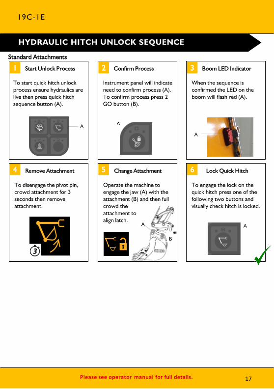
To start quick hitch unlock process ensure hydraulics are live then press quick hitch sequence button (A).
Start Unlock Process Confirm Process
Instrument panel will indicate need to confirm process (A). To confirm process press 2 GO button (B).
Boom LED Indicator
When the sequence is confirmed the LED on the boom will flash red (A).
Remove Attachment Change Attachment Lock Quick Hitch
To disengage the pivot pin, crowd attachment for 3 seconds then remove attachment.
Operate the machine to engage the jaw (A) with the attachment (B) and then full crowd the attachment to align latch.
To engage the lock on the quick hitch press one of the following two buttons and visually check hitch is locked.
Standard Attachments
HYDRAULIC HITCH UNLOCK SEQUENCE
19C-1E
A A
A
A
B
A
17
Please see operator manual for full details.
1 2 3
4 5
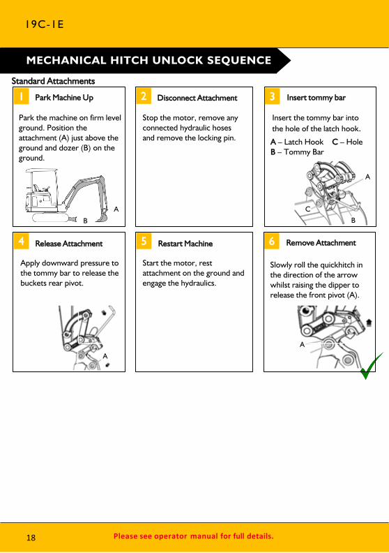
Park the machine on firm level ground. Position the attachment (A) just above the ground and dozer (B) on the ground.
Park Machine Up Disconnect Attachment
Stop the motor, remove any connected hydraulic hoses and remove the locking pin.
Insert tommy bar
Insert the tommy bar into the hole of the latch hook.
Release Attachment Restart Machine
Apply downward pressure to the tommy bar to release the buckets rear pivot.
Start the motor, rest attachment on the ground and engage the hydraulics.
Standard Attachments
MECHANICAL HITCH UNLOCK SEQUENCE
19C-1E
18
A – Latch Hook C – Hole B – Tommy Bar
6 Remove Attachment
Slowly roll the quickhitch in the direction of the arrow whilst raising the dipper to release the front pivot (A).
A
A
B
C
A
A
B
AB
Please see operator manual for full details.
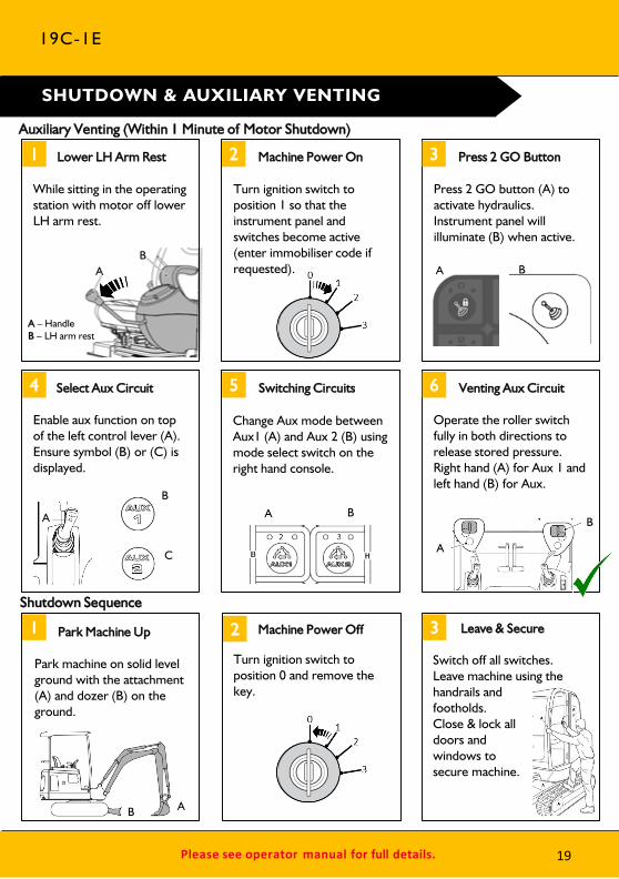
Shutdown Sequence
Auxiliary Venting (Within 1 Minute of Motor Shutdown)
1 2 3
4 5 6
While sitting in the operating station with motor off lower LH arm rest.
Lower LH Arm Rest Machine Power On
Turn ignition switch to position 1 so that the instrument panel and switches become active (enter immobiliser code if requested).
Press 2 GO Button
Press 2 GO button (A) to activate hydraulics. Instrument panel will illuminate (B) when active.
Select Aux Circuit Switching Circuits Venting Aux Circuit
Enable aux function on top of the left control lever (A). Ensure symbol (B) or (C) is displayed.
Operate the roller switch fully in both directions to release stored pressure. Right hand (A) for Aux 1 and left hand (B) for Aux.
A – HandleB – LH arm rest
1 2 3Park Machine Up Leave & Secure
Park machine on solid level ground with the attachment (A) and dozer (B) on the ground.
Switch off all switches. Leave machine using the handrails and footholds. Close & lock all doors and windows to secure machine.
SHUTDOWN & AUXILIARY VENTING
Change Aux mode between Aux1 (A) and Aux 2 (B) using mode select switch on the right hand console.
19C-1E
A B
A
B
C
A B
A
B
B A
19
Machine Power Off
Turn ignition switch to position 0 and remove the key.

Please see operator manual for full details.
CHARGING LEVELS & CHARGING
The machine is charged using the plug on the right hand side, as viewed from the rear of the machine. Note: there is no requirement for the machine power switch to be turned ON whilst charging.
Note: Only use the Genuine JCB Charge Cable supplied with the machine. Use an appropriate grounded industrial supply with correct AC (alternating current) input voltage.
If at any time a fault occurs when charging, the status LED light in Fig. 17 (A) illuminates red, unplug the charging cable and repeat the above steps. If further issues occur, unplug the charging cable and contact your local JCB Dealer. If there is a fault with the power supply the status LED will alternate green and red.
19C-1E
A – Battery full charge indicatorB – Low battery indicator
A – Charge indicator LEDB – Operating Status
C – Charging socketD – Charge cable
Fig. 16
Fig. 17
20
1) Connect the charge lead to the mains supply outlet and to the machine inlet
2) Depress the reset button on the inline RCD*3) Green status LED light will illuminate at charge
inlet (See (A) in Fig. 17)1) LED light will pulse when charging2) LED light will hold green when plugged
in and not charging4) Machine instrument panel will illuminate and
display state of charge*for 230V AC mains supply, when using 110V AC, an RCD is not provided

1. Park the machine on solid, level groundI. Release the two track leversII. Set the hand throttle dial to the idle position
2. Lower the dozer blade
3. Lower the excavator so the attachment is flat on the ground
4. Discharge the hydraulic pressure (see aux venting operation)
5. Isolate the controls and remove power switch key
Please see operator manual for full details.
A – Attachment flat on the groundB – Dozer blade lowered to ground
MAINTENANCE POSITION
19C-1E
Fig. 18
21
Please see operator manual for full details.
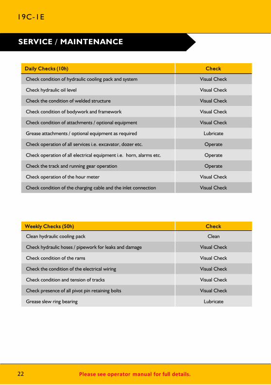
Daily Checks (10h) Check
Check condition of hydraulic cooling pack and system Visual Check
Check hydraulic oil level Visual Check
Check the condition of welded structure Visual Check
Check condition of bodywork and framework Visual Check
Check condition of attachments / optional equipment Visual Check
Grease attachments / optional equipment as required Lubricate
Check operation of all services i.e. excavator, dozer etc. Operate
Check operation of all electrical equipment i.e. horn, alarms etc. Operate
Check the track and running gear operation Operate
Check operation of the hour meter Visual Check
Check condition of the charging cable and the inlet connection Visual Check
Weekly Checks (50h) Check
Clean hydraulic cooling pack Clean
Check hydraulic hoses / pipework for leaks and damage Visual Check
Check condition of the rams Visual Check
Check the condition of the electrical wiring Visual Check
Check condition and tension of tracks Visual Check
Check presence of all pivot pin retaining bolts Visual Check
Grease slew ring bearing Lubricate
22
SERVICE / MAINTENANCE
19C-1E
Please see operator manual for full details.
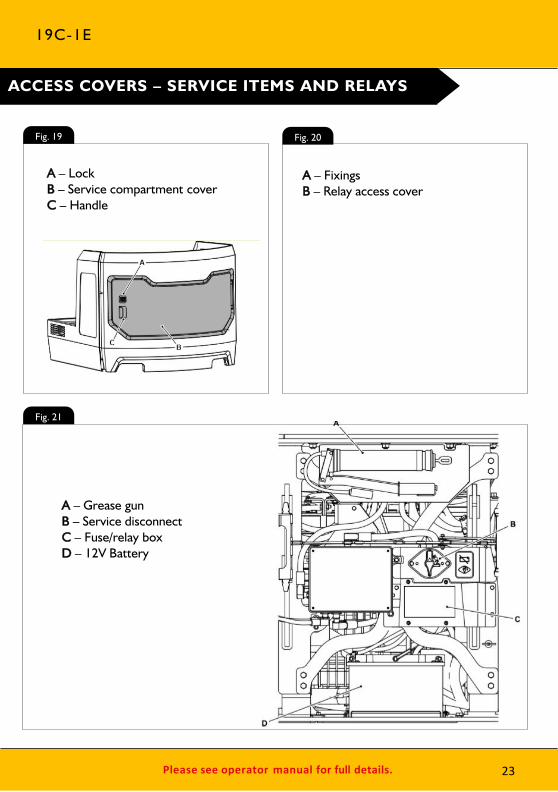
ACCESS COVERS – SERVICE ITEMS AND RELAYS
A – Grease gunB – Service disconnectC – Fuse/relay boxD – 12V Battery
A – LockB – Service compartment coverC – Handle
A – FixingsB – Relay access cover
19C-1E
Fig. 19 Fig. 20
Fig. 21
23

Please see operator manual for full details.
ACCESS COVERS – FLUID LEVELS AND FILL
A – Hydraulic tank filler capB – High voltage batteries charging pointC – Hydraulic oil level indicator
19C-1E
24
A – Hydraulic compartment coverB – Lock
Fig. 22
Fig. 23
Please see operator manual for full details.
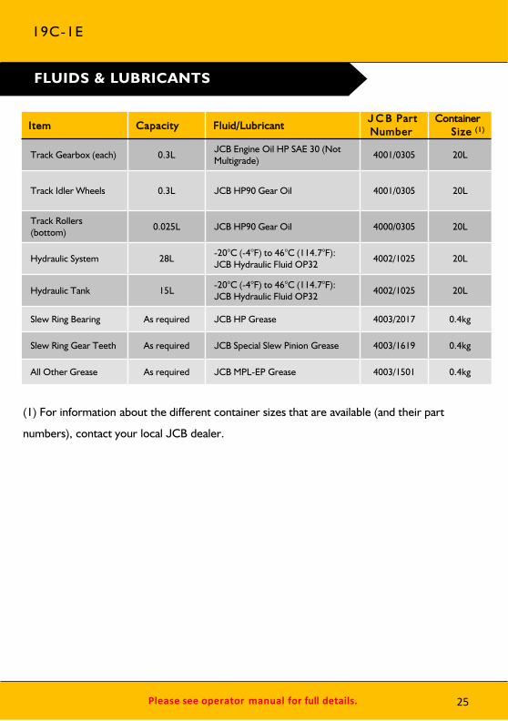
Item Capacity Fluid/LubricantJ C B Part Number
Container Size (1)
Track Gearbox (each) 0.3LJCB Engine Oil HP SAE 30 (Not Multigrade)
4001/0305 20L
Track Idler Wheels 0.3L JCB HP90 Gear Oil 4001/0305 20L
Track Rollers (bottom)
0.025L JCB HP90 Gear Oil 4000/0305 20L
Hydraulic System 28L-20°C (-4°F) to 46°C (114.7°F):JCB Hydraulic Fluid OP32 4002/1025 20L
Hydraulic Tank 15L-20°C (-4°F) to 46°C (114.7°F):JCB Hydraulic Fluid OP32
4002/1025 20L
Slew Ring Bearing As required JCB HP Grease 4003/2017 0.4kg
Slew Ring Gear Teeth As required JCB Special Slew Pinion Grease 4003/1619 0.4kg
All Other Grease As required JCB MPL-EP Grease 4003/1501 0.4kg
FLUIDS & LUBRICANTS
19C-1E
25
(1) For information about the different container sizes that are available (and their part
numbers), contact your local JCB dealer.

Please see operator manual for full details.26
DescriptionWeight
(kg) I n t en ded U s eH y d ra u l i c
R e q u i r eme n t s
Mechanical Quickhitch 13.7 Quick change of attachments None
Hydraulic Quickhitch 22 Quick change of attachments Quickhitch circuit
Bucket GP 150mm 20.2General excavation / Bulk loading
loose materialNone
Bucket GP 230mm 22.2General excavation / Bulk loading
loose materialNone
Bucket GP 300mm 24.4General excavation / Bulk loading
loose materialNone
Bucket GP 400mm 28.7General excavation / Bulk loading
loose materialNone
Bucket GP 460mm 30.3General excavation / Bulk loading
loose materialNone
Grading / Ditching Bucket 760mm
36.8Grading, finishing, landscaping &
DitchingNone
Grading / Ditching Bucket 1000mm
44.9Grading, finishing, landscaping &
DitchingNone
Earth Drill – 1500Nm 63.8 Drilling 160mm – 900mm holes 1x Hi-Flow aux service
Breaker – HM012T 107 Breaking up tarmac, concrete, rock 1x single acting aux service
Breaker –HM100Q 129 Breaking up tarmac, concrete, rock 1x single acting aux service
MACHINE ATTACHMENTS
19C-1E
ATTACHMENT WEIGHTS ARE A GUIDE ONLY, ALWAYS CHECK YOUR OWN ATTACHMENTS
Description I n t en ded U s e
110V Charging Cable Charging from a 110V supply (IEC60309 110V 16A)
230V Charging Cable Charging from a 230V supply (IEC60309 230V 16A)
Type E, F (Shuko) 230V Charging Cable Charging from a 230V supply (Type E, F (Shuko) 230V 16A)
ADDITIONAL ATTACHMENTS

Please see operator manual for full details.
Issue / FAQ Resolution / Answer
My machine will not start Ensure the service disconnect is turned on. Verify the start up sequence has been followed (Page 16).
If machine still will not start contact dealer
I can’t activate the Hydraulics Here are some of the possible reasons:
• When the machine hydraulics are live and you lift the left hand pod you will need to re-select ‘2-GO’ when the pod is returned to the down position.
• The left hand pod is in the raised position.• There is a fault on the keypad.• Motor isn’t switched on.• If there is an error on the machine and an error code is
displayed on the LCD screen – which would inhibit the hydraulics.
If hydraulics still won’t activate contact dealer
Why is there an audible buzzer in the cab when I’m lifting a large load?
The lift overload warning system has detected a load that is near the limits of the machine, reduce load to prevent machine overturning.
Can I disable the lift overload warning indicator when not object handling?
To disable lift overload warning indicator when not object handling, press button ‘C’ on the switch panel (refer to page 13).
500hrs Greasing - Does it matter if greased every day?
No, there is no impact on life of the pivot pins or bushes
TROUBLESHOOTING / FAQ’S
19C-1E
27
Please see operator manual for full details.
Issue / FAQ Resolution / Answer
500hrs Greasing - Do the bushes need to be replaced at 500hrs?
No, just grease and continue work
500hrs Greasing - After the first 500hrs do the bushes then need greasing daily?
No, the bushes wont need greasing until the next 500hrs
500hrs Greasing - Without daily greasing what cleans all the dirt out of the bush?
Machine is fitted with one way seals stopping dirt entering the bush but allowing old grease out when greasing
How do I switch from ISO to SAE control patterns?
The control pattern change-over switch is located under the operator station. • Position 1 = SAE • Position 2 = ISOAlways refer to the in cab display for confirmation of control pattern selection.
How do I activate continuous auxiliary flow?
To activate constant flow, select right hand finger button on the right hand joystick. Please refer to page 15 for joystick control layout.
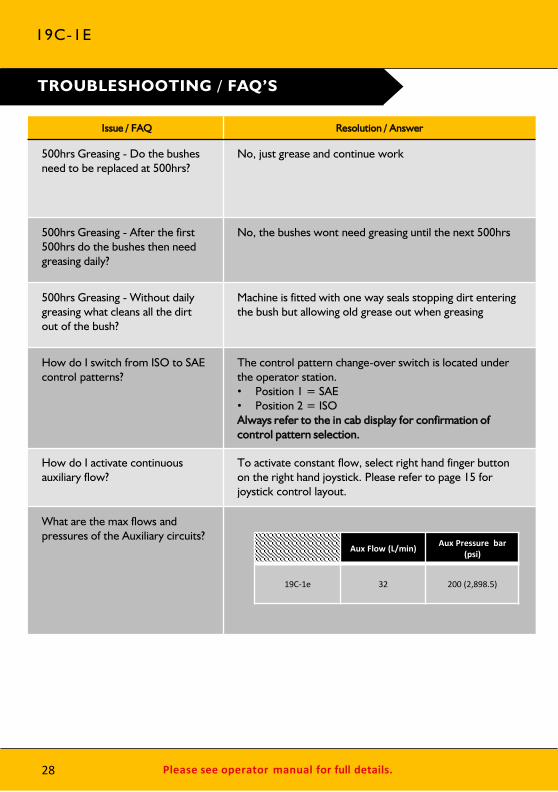
What are the max flows and pressures of the Auxiliary circuits?
28
TROUBLESHOOTING / FAQ’S
19C-1E
Aux Flow (L/min) Aux Pressure bar
(psi)
19C-1e 32 200 (2,898.5)
All rights reserved. No part of this publication may be reproduced, stored in a retrieval system, or transmitted in anyform or by any other means, electronic, mechanical, photocopying or otherwise, without prior permission from J C BSales. All references in this publication to operating weights, sizes, capacities and other performance measurements areprovided for guidance only and may vary dependant upon the exact specification of the machine. They should nottherefore be relied upon in relation to suitability for a particular application. Guidance and advice should always besought from your J C B Dealer’. J C B reserves the right to change specifications without notice. Illustrations andspecifications shown may include optional equipment and accessories.
J C B Sales Limited, Rocester, Staffordshire, United Kingdom ST14 5JP Tel: +44 1889 590312 Email: [email protected]
Download the very latest information on this product range at: www.jcb.com
The J C B logo is a registered trademark of J C Bamford Excavators Ltd. ©2009 J C B Sales.