Linear High Gain Dual Band Notch Scanning Beam Circularly ...
14
Linear High Gain Dual Band Notch Scanning Beam Circularly Polarized Electronically Steerable Smart Antenna Array for 2.4 GHz W-lan and 5.8 GHz UHF RFID Reader Application Without any Central Null using Buttler-Matrix Beam-former Formulation. Author:Joyanto Roychoudhary, Department of Electronics and Communication Engineering, B.P.Poddar Institute Of Management and Technology, 137, VIP Road,Poddar Vihar,Kol-700 052. Email:[email protected] Abstract: An antenna Array is subjected to the same measurable parameters as any antenna but these parameters change as the array is scanned. In other words, we can say that the array characteristics become a response to the periodic environment and the resulting array parameters have to be determined as a function of scan. As far as the individual isolated elements in the array are concerned, they behave very differently when embedded in an array, still the elements determine the array polarization, fundamental bandwidth and gross features of the array radiation pattern and the inter-element mutual-coupling within the array lattice. The only condition imposed by the array is that the spacing between the elements need to be small enough to avoid the grating lobes or “blindness”. In this paper we propose a circularly polarized scanning beam array which has dual band notching characteristics in the 2.4 GHz and 5.8 GHz range. This array is able to scan the whole 0-360° of angular space providing enormous spacio-temporal angular diversity and has a high gain of over 15dBi. The axial ratio has been plotted as a function of frequency in the X-band (8-12 GHz) and it has been found that the array provides an axis ratio of 1:2(major axis=0.8; minor axis=0.4) i.e. Perfect polarization ellipse at 5.8 GHz. Also the array is able to notch two different frequencies for “WLAN” as well as “UHF RFID Reader” application in the 2.4 and 5.8 GHZ band. At the end of the paper a Buttler Matrix formulation of a Multi-Beam Beam Former Array is carried out and simulated. Simulation Results substantiate with experimental and theoretical outcomes. Keywords: Scanning beam, Beam former, UHF, RFID, notch, Buttler Matrix, axial ratio. I. Introduction: I.[a]. Electronic Scanning and the Phased Array The potential for increased target handling capacity available in “Track While Scan” radars is limited by the requirement to steer the radar antenna mechanically. Existing mechanical scanning methods are comparatively slow and require large power concern in order to respond rapidly enough to deal with large numbers of high speed manoevearing targets. With mechanically scanned systems, optimum radar beam positioning patterns can reduce reaction times and increase target capacity. With ESA, the radar beams are positioned almost instantaneously and completely without the inertia, time lags, and vibration of mechanical systems. Since the numerical superiority of adversaries is expected to remain large, electronic scanning can offset that advantage. The fundamental principles underlying the concept of electronic beam steering are derived from electromagnetic radiation theory employing constructive and destructive interference. IEEE-SEM, Volume 10, Issue 6, June-2019 ISSN 2320-9151 182 Copyright © 2019 IEEE-SEM Publications
-
Upload
khangminh22 -
Category
Documents
-
view
0 -
download
0
Transcript of Linear High Gain Dual Band Notch Scanning Beam Circularly ...
Linear High Gain Dual Band Notch Scanning Beam Circularly Polarized
Electronically Steerable Smart Antenna Array for 2.4 GHz W-lan and 5.8
GHz UHF RFID Reader Application Without any Central Null using
Buttler-Matrix Beam-former Formulation.
Author:Joyanto Roychoudhary, Department of Electronics and Communication Engineering, B.P.Poddar Institute Of Management and Technology,
137, VIP Road,Poddar Vihar,Kol-700 052. Email:[email protected]
Abstract:
An antenna Array is subjected to the same measurable parameters as any antenna but these parameters change as the array is
scanned. In other words, we can say that the array characteristics become a response to the periodic environment and the
resulting array parameters have to be determined as a function of scan. As far as the individual isolated elements in the array
are concerned, they behave very differently when embedded in an array, still the elements determine the array polarization,
fundamental bandwidth and gross features of the array radiation pattern and the inter-element mutual-coupling within the
array lattice. The only condition imposed by the array is that the spacing between the elements need to be small enough to avoid
the grating lobes or “blindness”. In this paper we propose a circularly polarized scanning beam array which has dual band
notching characteristics in the 2.4 GHz and 5.8 GHz range. This array is able to scan the whole 0-360° of angular space
providing enormous spacio-temporal angular diversity and has a high gain of over 15dBi. The axial ratio has been plotted as a
function of frequency in the X-band (8-12 GHz) and it has been found that the array provides an axis ratio of 1:2(major
axis=0.8; minor axis=0.4) i.e. Perfect polarization ellipse at 5.8 GHz. Also the array is able to notch two different frequencies for
“WLAN” as well as “UHF RFID Reader” application in the 2.4 and 5.8 GHZ band. At the end of the paper a Buttler Matrix
formulation of a Multi-Beam Beam Former Array is carried out and simulated. Simulation Results substantiate with
experimental and theoretical outcomes.
Keywords: Scanning beam, Beam former, UHF, RFID, notch, Buttler Matrix, axial ratio.
I. Introduction:
I.[a]. Electronic Scanning and the Phased Array
The potential for increased target handling capacity available in “Track While Scan” radars is limited by the
requirement to steer the radar antenna mechanically. Existing mechanical scanning methods are comparatively slow and
require large power concern in order to respond rapidly enough to deal with large numbers of high speed manoevearing
targets.
With mechanically scanned systems, optimum radar beam positioning patterns can reduce reaction times and
increase target capacity. With ESA, the radar beams are positioned almost instantaneously and completely without
the inertia, time lags, and vibration of mechanical systems. Since the numerical superiority of adversaries is
expected to remain large, electronic scanning can offset that advantage.
The fundamental principles underlying the concept of electronic beam steering are derived from electromagnetic
radiation theory employing constructive and destructive interference.
IEEE-SEM, Volume 10, Issue 6, June-2019 ISSN 2320-9151
182
Copyright © 2019 IEEE-SEM Publications

Methods of Beam Steering:
Previously the literature discusses about the theory required to compute the relative phase shift between adjacent
radiating elements in order to position the beam of an array-type antenna to a specific angle off of the antenna
boresight axis. In practice there are three methods of accomplishing this phase difference.
Time Delay Scanning
The employment of time delay as a means of achieving the desired phase relationships between elements allows
greater flexibility in frequency utilization than other methods. However, in practice the use of coaxial delay
lines or other means of timing at high power levels is impractical due to increased cost, complexity, and weight.
Frequency Scanning
One of the simpler methods of phased-array radar implementation is frequency scanning. This method is also
relatively inexpensive The length of the serpentine wavelength line (l) is chosen such that for some centre
frequency, f0, the length of signal travel between elements is an integral number of wavelengths, or
= n (n = any integer greater than zero)
where
0 = wavelength in the serpentine line at frequency f0.
Phase Scanning
In a phase-scanned radar system, the radiating elements are fed from a radar transmitter through phase-shifting
networks or "phases." The aim of the system is again to position the beam at any arbitrary angle, at any time. In
this case the means of accomplishing the phase shift at each element is simply to shift the phase of the incoming
energy to each element. These phases are adjustable over the range 0 to + 2 radians. The task of the system is to
compute the phase shift required for each element, and set each phase to the proper value to accomplish the
desired beam offset.
Fig.1. Electronically Scanned Arrays.
IEEE-SEM, Volume 10, Issue 6, June-2019 ISSN 2320-9151
183
Copyright © 2019 IEEE-SEM Publications
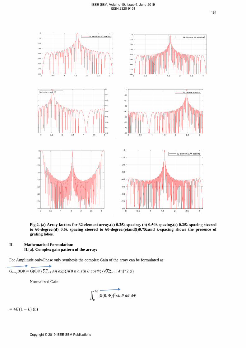
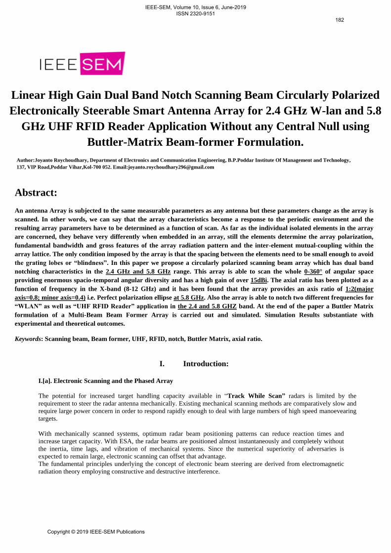
Fig.2. (a) Array factors for 32-element array.(a) 0.25λ spacing. (b) 0.50λ spacing.(c) 0.25λ spacing steered
to 60-degree.(d) 0.5λ spacing steered to 60-degree.(e)and(f)0.75λand λ-spacing shows the presence of
grating lobes.
II. Mathematical Formulation:
II.[a]. Complex gain pattern of the array:
For Amplitude only/Phase only synthesis the complex Gain of the array can be formulated as:
Garray(θ,Φ)= G(θ,Φ) ∑ ∑
(i)
Normalized Gain:
∬
(ii)
IEEE-SEM, Volume 10, Issue 6, June-2019 ISSN 2320-9151
184
Copyright © 2019 IEEE-SEM Publications
Where L=antenna loss factor.
Βn=An/exp(jψn) ; ψn= -K0 (n-1) a sin θ0.(iii)
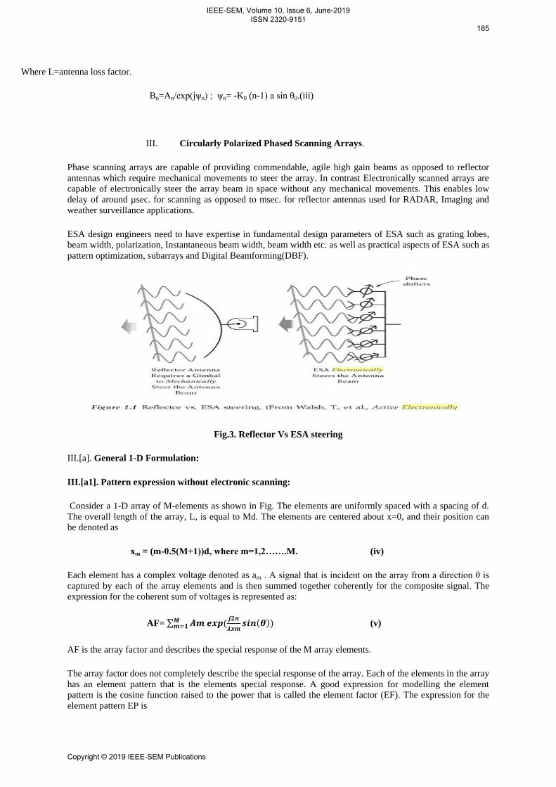
III. Circularly Polarized Phased Scanning Arrays.
Phase scanning arrays are capable of providing commendable, agile high gain beams as opposed to reflector
antennas which require mechanical movements to steer the array. In contrast Electronically scanned arrays are
capable of electronically steer the array beam in space without any mechanical movements. This enables low
delay of around µsec. for scanning as opposed to msec. for reflector antennas used for RADAR, Imaging and
weather surveillance applications.
ESA design engineers need to have expertise in fundamental design parameters of ESA such as grating lobes,
beam width, polarization, Instantaneous beam width, beam width etc. as well as practical aspects of ESA such as
pattern optimization, subarrays and Digital Beamforming(DBF).
Fig.3. Reflector Vs ESA steering
III.[a]. General 1-D Formulation:
III.[a1]. Pattern expression without electronic scanning:
Consider a 1-D array of M-elements as shown in Fig. The elements are uniformly spaced with a spacing of d.
The overall length of the array, L, is equal to Md. The elements are centered about x=0, and their position can
be denoted as
xm = (m-0.5(M+1))d, where m=1,2…….M. (iv)
Each element has a complex voltage denoted as am . A signal that is incident on the array from a direction θ is
captured by each of the array elements and is then summed together coherently for the composite signal. The
expression for the coherent sum of voltages is represented as:
AF= ∑
(v)
AF is the array factor and describes the special response of the M array elements.
The array factor does not completely describe the special response of the array. Each of the elements in the array
has an element pattern that is the elements special response. A good expression for modelling the element
pattern is the cosine function raised to the power that is called the element factor (EF). The expression for the
element pattern EP is
IEEE-SEM, Volume 10, Issue 6, June-2019 ISSN 2320-9151
185
Copyright © 2019 IEEE-SEM Publications

EP=
(iv).
In real applications, the EP does not go to 0 at θ =90°. An ESA, in its installed environment or in a measurement
range, will be subject to diffraction and reflections near the edges of the array that will modify the EP near the
edges.
F(θ) =
. ∑
(vii)
III.[b]. Pattern expression with Electronic Scanning:
Scanning the beam of the array requires adjusting the phase or time delay of each element in the array. By
rewriting the equation in eq. (iv) above and expanding the complex voltage at each element the resulting eq.
becomes
AF = am
(viii) (v)
F(θ) =
.∑
(ix)
Fig.4. (a) plot of scan vs tilt angle.(b) Frequency vs. impedence of scanning array.(c) Beamwidth as a
function of scan angle and frequency at k=1.(d) Plot of grating lobes.(e) and (f) Array pattern squint.
IEEE-SEM, Volume 10, Issue 6, June-2019 ISSN 2320-9151
186
Copyright © 2019 IEEE-SEM Publications
IV. Beam former configurations using FPGA, DSP, etc.
The FPGA technology has lately become an attractive alternative for implementation of a wide range of DSP
applications. Here we discuss an implementation of radar phase array antenna system. The final implementation
of this beam former is to be used in a demonstrator of such a radar system. The critical component of the digital
beam former when both throughput and chip area is considered is the complex multiplication. Here a bit-serial
complex multiplier based on distributed arithmetic has been identified as a suitable structure for implementation
in an FPGA circuit.
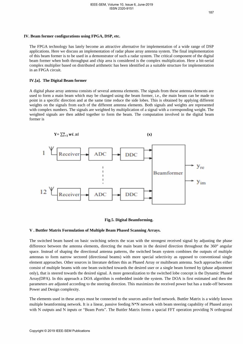
IV.[a]. The Digital Beam former
A digital phase array antenna consists of several antenna elements. The signals from these antenna elements are
used to form a main beam which may be changed using the beam former, i.e., the main beam can be made to
point in a specific direction and at the same time reduce the side lobes. This is obtained by applying different
weights on the signals from each of the different antenna elements. Both signals and weights are represented
with complex numbers. The signals are weighted by multiplication of a signal with a corresponding weight. The
weighted signals are then added together to form the beam. The computation involved in the digital beam
former is
Y= ∑ (x)
Fig.5. Digital Beamforming.
V . Buttler Matrix Formulation of Multiple Beam Phased Scanning Arrays.
The switched beam based on basic switching selects the scan with the strongest received signal by adjusting the phase
difference between the antenna elements, directing the main beam in the desired direction throughout the 360° angular
space. Instead of shaping the directional antenna patterns, the switched beam system combines the outputs of multiple
antennas to form narrow sectored (directional beams) with more special selectivity as opposed to conventional single
element approaches. Other sources in literature defines this as Phased Array or multibeam antenna. Such approaches either
consist of multiple beams with one beam switched towards the desired user or a single beam formed by (phase adjustment
only), that is steered towards the desired signal. A more generalization to the switched lobe concept is the Dynamic Phased
Array(DPA). In this approach a DOA algorithm is embedded inside the system. The DOA is first estimated and then the
parameters are adjusted according to the steering direction. This maximizes the received power but has a trade-off between
Power and Design complexity.
The elements used in these arrays must be connected to the sources and/or feed network. Buttler Matrix is a widely known
multiple beamforming network. It is a linear, passive feeding N*N network with beam steering capability of Phased arrays
with N outputs and N inputs or “Beam Ports”. The Buttler Matrix forms a spacial FFT operation providing N orthogonal
IEEE-SEM, Volume 10, Issue 6, June-2019 ISSN 2320-9151
187
Copyright © 2019 IEEE-SEM Publications

beams when N is a power of 2. A Buttler Matrix feed array can scan the entire 360° angular space and the appropriate beam
can be selected by an RF switch. A Buttler Matrix also has the capability of beam steering by exciting the beam ports with
amplitude and Phase weights followed by a variable uniform phase taper. A total of N/2*log2 N hybrids and N/2 *
log2(N-1) fixed phase shifters are used to form the network. The hybrids can be either 90° or 180° 3-dB hybrids, depending
upon the symmetrical distance of the beams towards the broadside or whether one of the beams is to be in the broadside
boresight direction.
A Buttler-Matrix serves two functions:
(a) Distribution of RF signal to radiating antenna elements.
(b) Orthogonal beamforming and beam steering.
Fig.6. (a) Buttler Matrix Beamforming Array.(b) Window function(Amplitude distribution) of a 43-
element array.
IEEE-SEM, Volume 10, Issue 6, June-2019 ISSN 2320-9151
188
Copyright © 2019 IEEE-SEM Publications

Fig.7.(a) Smart antenna.(b) Coverage pattern for switched beam and adaptive array.(c) Multiple-
beamforming.(d) A 4*4 Buttler Matrix.(e) Orthogonal beams of an 8*8 Buttler Matrix.
VI. RADIO FREQUENCY IDENTIFICATION(RFID)
Radio-frequency identification (RFID) technology enables remote and automated gathering and sending of
information between RFID tags or transponders and readers using a wireless link. Using RFID, the exchange of
data between tags and readers is rapid, automatic and does not require direct contact or line of sight.
When a Card (tag) is brought near the RFID reader, it tries to communicate with the tag, receives the data and
decodes it. Finally, it sends the data over the TX line. The UART module in MCU receives the data and thus used
for further applications. By employing RFID, much secured entry systems can be developed without incurring huge
costs. These are the reasons of excessive use of RFID technology.
IEEE-SEM, Volume 10, Issue 6, June-2019 ISSN 2320-9151
189
Copyright © 2019 IEEE-SEM Publications

Fig. 8(a) RFID module.(b) Frequency range of RFID.(c) Working principle of RFID.(d) Active and
Passive RFID tags.(e) Types of RFID tags.
VII. Results:
In the initial part of the paper a 100-element antenna array gain was synthesized using Genetic Algorithm. The
optimized gain obtained after applying Meta-Heuristics to the problem Space was obtained to be -19.17dBi.. It
took about 15 minutes to complete the simulation over a 1-GHz Quad-Core Pentium processor with RAM
expanded to 8GB.The algorithmic parameters are:
Posize=500
Mutrate=0.10
No. of bits=10
No. of generations=10000
The designed array antenna was applied at the loadside of an X-band(8-12 GHz) microwave test bench and the
antenna gain was estimated. It was observed that the optimization results substantiates with the experimental
outcome. Also the return loss at the measured VSWR of 1.5 was calculated. A typical return loss value of an
ESA is -13dB and experimentally it was found out to be -13.97dB which is far excellent.
10-Jun-2019 14:31:09
optimized function is testfunction
popsize = 300 mutrate = 0.10 # par = 43
#generations=1000 best cost= 0.11
Calculated Gain=-20*log(best cost)=-19.17dBi.
best solution or array co-efficients(Amplitude only):
0.17595 0.01173 0.13099 0.21603 0.10948 0.21408 0.044966 0.053763 0.025415 0.8739
0.021505 0.19355 0.40567 0.77126 0.9912 0.46334 0.30596 0.71554 0.24438 0.032258
0.3304 0.11437 0.066471 0.21505 0.91789 0.44966 0.0029326 0.012708 0.12805 0.041056
0.40469 0.63539 0.93646 0.13587 0.083089 0.30401 0.42033 0.5826 0.82502 0.54936
IEEE-SEM, Volume 10, Issue 6, June-2019 ISSN 2320-9151
190
Copyright © 2019 IEEE-SEM Publications
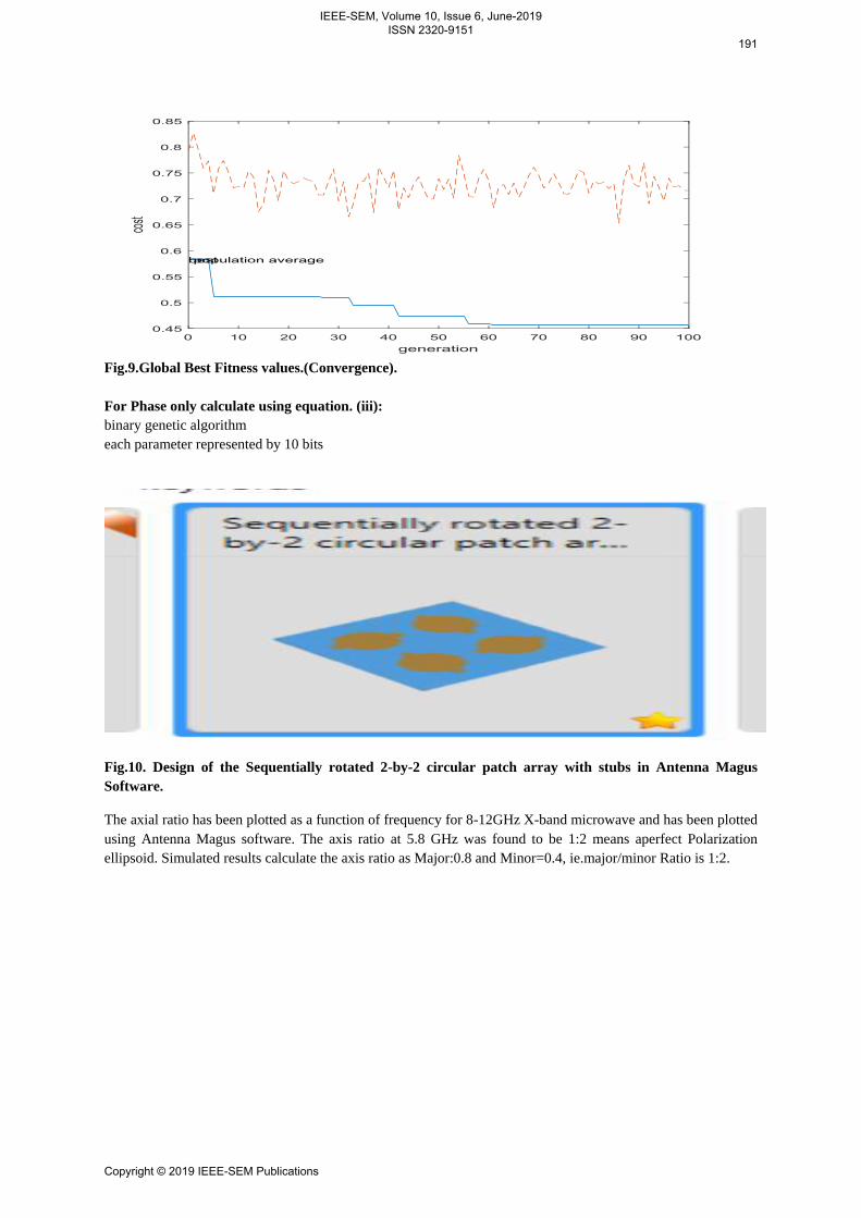
Fig.9.Global Best Fitness values.(Convergence).
For Phase only calculate using equation. (iii):
binary genetic algorithm
each parameter represented by 10 bits
Fig.10. Design of the Sequentially rotated 2-by-2 circular patch array with stubs in Antenna Magus
Software.
The axial ratio has been plotted as a function of frequency for 8-12GHz X-band microwave and has been plotted
using Antenna Magus software. The axis ratio at 5.8 GHz was found to be 1:2 means aperfect Polarization
ellipsoid. Simulated results calculate the axis ratio as Major:0.8 and Minor=0.4, ie.major/minor Ratio is 1:2.
IEEE-SEM, Volume 10, Issue 6, June-2019 ISSN 2320-9151
191
Copyright © 2019 IEEE-SEM Publications

The first fig. below shows the plot of axial ratio vs Normalized frequency for a scanning array. The second
figure shows the Polarization ellipse and the third fig. shows the scanning beam beamforming simulation for
Buttler-Matrix formulation of Electronically steered Arrays. Both second and third figures are plotted using
MATLAB 2019a Phased Array Antenna System toolbox.
VIII. Acknowledgement:
Our special thanks are due for the outrageous help given to us by the Lab Assistants for the design and
experimental simulation and testing of the antenna array in the college premises and the departmental
Microwave Laboratory of ECE departmentand also the recent inaugurated R&D lab. Also last but not
the least I thank all the faculties and staff of B.P.Poddar Institute Of Management and Technology here
at Kolkata without which our work could not achieve a grand success.
IEEE-SEM, Volume 10, Issue 6, June-2019 ISSN 2320-9151
192
Copyright © 2019 IEEE-SEM Publications

IX. References:
[1] Woodward, P. M., and J. D. Lawson, „„The Theoretical Precision with Which an ArbitraryRadiation Pattern
May Be Obtained from a Source of Finite Size,‟‟J. AIEE,Vol. 95,Pt. 3, September 1948, pp. 362–370.
[2] Ricardi, L. J., „„Adaptive Antennas,‟‟ Ch. 3 inAntenna Engineering Handbook,R. C. Johnson and H. Jasik,
(eds.), New York: McGraw-Hill, 1984, 1961.
[3] Klein, C. E., „„Design of Shaped Beam Antennas Through Minimax Gain Optimization,‟‟IEEE Trans. on
Antennas and Propagation,Vol. AP-32, No. 9, September 1984,pp. 963–968.
[4] Galindo-Israel, V., S. W. Lee, and R. Mittra, „„Synthesis of Laterally Displaced ClusterFeed for a Reflector
Antenna With Application to Multiple Beams and Contoured Pat-terns,‟‟IEEE Trans. on Antennas and
Propagation,Vol. AP-26, No. 2, March 1978,pp. 220–228.
[5] Thomas, D. T., „„Multiple Beam Synthesis of Low Sidelobe Patterns in Lens Fed Arrays,‟‟IEEE Trans. on
Antennas and Propagation,Vol. AP-26, No. 6, November 1978,pp. 883–886.
[6] Butler, J., and R. Lowe, „„Beam Forming Matrix Simplifies Design of Electronically ScannedAntennas,‟‟Elect.
Design,Vol. 9, April 12, 1961, pp. 170–173
[7] Shelton, J. P., and K. S. Kelleher, „„Multiple Beams from Linear Arrays,‟‟IEEE Trans. onAntennas and
Propagation,Vol. AP-9, March 1961, pp. 154–161.
[8] Allen, J. L., „„A Theoretical Limitation on the Formation of Lossless Multiple Beams inLinear Arrays,‟‟IRE
Trans.,Vol. AP-9, July 1961, pp. 350–352.
[9] Kahn, W. H., and H. Kurss, „„The Uniqueness of the Lossless Feed Network for aMultibeam Array,‟‟IEEE
Trans. on Antennas and Propagation,Vol. AP-10, January1962, pp. 100–101.
[10] White, W. D., „„Pattern Limitation in Multiple Beam Antennas,‟‟IRE Trans.,Vol. AP-10,July 1962, pp. 430–
436.
[11] Stein, S., „„Cross Couplings Between Feed Lines of Multibeam Antennas Due to BeamOverlap,‟‟IEEE Trans.
on Antennas and Propagation,Vol. AP-10, September 1962,pp. 548–557.
[12] Johansson, J. F.,Theoretical Limits for Aperture Efficiency in Multi-Beam Antenna Sys-tems,Research Report
#161, Dept. of Radio and Space Systems, Chalmers University ofTechnology, Gothenburg, Sweden, August 1978.
[13] Dufort, E. C., „„Optimum Low Sidelobe High Crossover Multiple Beam Antennas,‟‟IEEETrans. on Antennas
and Propagation,Vol. AP-33, No. 9, September 1985, pp. 946–954.
[14] Butler, J. L., „„Digital, Matrix, and Intermediate Frequency Scanning,‟‟ Ch. 3 inMicrowaveScanning
Antennas,R. C. Hansen, (ed.), Los Altos, CA: Peninsula Publishing, 1985.
468Special Array Feeds for Limited Field-of-View and Wideband Arrays
[15] Levy, R., „„A High Power x-Band Butler Matrix,‟‟Military Microwaves: MM-82,England:Microwave
Exhibitors and Publishers, Ltd., 1992.
[16] Blass, J., „„The Multidirectional Antenna: A New Approach to Stacked Beams,‟‟1960 IREInternational
Convention Record,Pt. 1, pp. 48–50.
[17] Sletten, C. J., „„Multibeam and Scanning Reflector Antennas,‟‟ Ch. 7 inReflector andLens Antennas: Analysis
and Design Using Personal Computers,C. J. Sletten, (ed.),Norwood, MA: Artech House, 1988.
[18] McGrath, D. T., „„Constrained Lenses,‟‟ Ch. 6 inReflector and Lens Antennas: Analysisand Design Using
Personal Computers,C. J. Sletten, (ed.), Norwood, MA: Artech House,1988.
[19] Lee, J. J., „„Lens Antennas,‟‟ Ch. 16 inAntenna Handbook: Theory, Applications, andDesign,Y. T. Lo and S.
W. Lee, (eds.), New York: Van Nostrand Reinhold, 1988.
[20] Rotman, W., and R. F. Turner, „„Wide Angle Microwave Lens for Line Source Applica-
tions,‟‟IEEETrans.onAntennasandPropagation,Vol.AP-11,1963,pp. 623–632.
[21] Archer, D., „„Lens Fed Multiple Beam Arrays,‟‟Microwave Journal,October 1975,pp. 37–42.
[22] Ajioka, J. S., and J. L. McFarland, „„Beamforming Feeds,‟‟ Ch. 19 inAntenna Handbook:Theory, Applications,
and Design,Y. T. Lo and S. W. Lee, (eds.), New York: Van NostrandReinhold, 1988.
[23] Rusch, W. V. T., et al., „„Quasi Optical Antenna Design and Applications,‟‟ Ch. 3 inTheHandbook of Antenna
Design,A. W. Rudge, et al., (eds.), Vol. 1, London, England: PeterPeregrinus, 1982.
[24] Lo, Y. T., „„On the Beam Deviation Factor of a Parabolic Reflector,‟‟IEEE Trans. onAntennas and
Propagation,Vol. AP-8, 1960, pp. 347–349.
[25] Ruze, J., „„Lateral Feed Displacement in a Paraboloid,‟‟IEEE Trans. on Antennas andPropagation,Vol. AP-13,
September 1965, pp. 660–665.
[26] Imbriale, W., et al., „„Large Lateral Feed Displacement in a Parabolic Reflector,‟‟IEEETrans. on Antennas and
Propagation,Vol. AP-22, No. 6, November 1974, pp. 742–745.
[27] Rusch, W. V. T., and A. C. Ludwig, „„Determination of the Maximum Scan-Gain Contoursof a Beam-
Scanning Paraboloid and Their Relation to the Petzval Surface,‟‟IEEE Trans.on Antennas and Propagation,Vol.
AP-21, March 1973, pp. 141–147.
[28] Sletten, C. J., „„Reflector Antennas,‟‟ Ch. 16 inAntenna Theory, Part 2,R. E. Collin andF. J. Zucker, (eds.),
New York: McGraw-Hill, 1969.
IEEE-SEM, Volume 10, Issue 6, June-2019 ISSN 2320-9151
193
Copyright © 2019 IEEE-SEM Publications

[29] Tang, R., „„Survey of Time-Delay Steering Techniques,‟‟Phased Array Antennas: Proc.1970 Phased Array
Antenna Symp.,Dedham, MA: Artech House, 1972, pp. 254–260.
[30] Mailloux, R. J., and P. Blacksmith, „„Array and Reflector Techniques for Airport PrecisionApproach
Radars,‟‟Microwave J.,October 1974, pp. 35–64.
[31] Vendik, G. G., „„Synthesis of a Linear Array with Non-Mechanical Beam Swinging,‟‟ (inRussian),Izvestiya
Vuzov-Radiotekhnika,Vol. 3, No. 1, January 1960, pp. 77–86.
[32] Kantorovitch, M. I., and V. Yu. Petrun‟kin, „„On the Minimum Number of Elements inan Antenna with
Electrical Beam Swinging,‟‟ (in Russian),Radiotekhnika & Electronika,Vol. 6, No. 12, December 1961, pp. 1982–
1988.
[33] Patton, W., „„Limited Scan Arrays,‟‟Phased Array Antennas: Proc. 1970 Phased ArraySymp.,A. A. Oliner and
G. A. Knittel, (eds.), Dedham, MA: Artech House, 1972,pp. 254–270.
[34] Stangel, J., „„A Basic Theorem Concerning the Electronic Scanning Capabilities of Anten-nas,‟‟URSI
Commission VI, Spring Meeting,June 11, 1974.
[35] Borgiotti, G. V., „„Degrees of Freedom of an Antenna Scanned in a Limited Sector,‟‟IEEEG-AP Int.
Symp.,1975, pp. 319–320.
[36] Mailloux, R. J., „„An Overlapped Subarray for Limited Scan Applications,‟‟IEEE Trans.on Antennas and
Propagation,Vol. AP-22, No. 3, May 1974, pp. 487–489.
8.3 Wideband Scanning Systems469
[37] Mailloux, R. J., and G. R. Forbes, „„An Array Technique with Grating-Lobe Suppressionfor Limited Scan
Application,‟‟IEEE Trans. on Antennas and Propagation,Vol. AP-21,No. 5, September 1973, pp. 597–602.
[38] Mailloux, R. J., L. Zahn, A. Martinez, and G. Forbes, „„Grating Lobe Control in LimitedScan Arrays,‟‟IEEE
Trans. on Antennas and Propagation,Vol. AP-27, No. 1,January 1979, pp. 79–85.
[39] Tsandoulas, G. N., and W. D. Fitzgerald, „„Aperture Efficiency Enhancement in Dielec-trically Loaded
Horns,‟‟IEEE Trans. on Antennas and Propagation,Vol. AP-20, No. 1,January 1972, pp. 69–74.
[40] Mailloux, R. J., „„Synthesis of Spatial Filters With Chebyshev Characteristics,‟‟IEEETrans. on Antennas and
Propagation,Vol. AP-24, No. 2, March 1976, pp. 174–181.
[41] Franchi, P. R., and R. J. Mailloux, „„Theoretical and Experimental Study of Metal GridAngular Filters for
Sidelobe Suppression,‟‟IEEE Trans. on Antennas and Propagation,Vol. AP-31, No. 3, May 1983, pp. 445–450.
[42] Skobelev, S. P., „„Methods of Constructing Optimum Phased-Array Antennas for LimitedField of View,‟‟IEEE
Antennas and Propagation Magazine,Vol. 40, No. 2, April 1998,pp. 39–49.
[43] Mailloux, R. J., and P. R. Caron, „„A Class of Phase Interpolation Circuits for ScanningPhased Arrays,‟‟IEEE
Trans. on Antennas and Propagation,Vol. AP-18, No. 1, January1970, pp. 114–116.
[44] Skobelev, S. P., and A. S. Vyazigin, „„Forming Flat-Topped Element Patterns in AntennaArrays of Two-Mode
Waveguides,‟‟Electronics Letters,Vol. 29, No. 22, July 1993,pp. 1326–1327.
[45] Vyazigin, A. S., and S. P. Skobelev, „„Analysis and Optimization of an Array of Dual-Mode Waveguides with
Slotted Elements of Coupling,‟‟ (in Russian),Radiotekhnika,No. 1, 1996, pp. 30–32.
[46] Wheeler, H. A., „„Antenna System Having Modular Coupling Network,‟‟ U.S. Patent No.4143379, Int. Cl.H
01Q 3/26, 1979.
[47] Lopez, A. R., „„Array Antenna System,‟‟ U.S. Patent No. 4321605, Int. Cl.H 01 Q 21/00,1982.
[48] Dufort, E. C., „„Constrained Feeds for Limited Scan Arrays,‟‟IEEE Trans. on Antennasand Propagation,Vol.
AP-26, May 1978, pp. 407–413.
[49] Kachwalla, Z., „„A Limited-Scan Linear Array Using Overlapping Subarrays,‟‟Journal ofElectrical and
Electronics Engineering,Vol. 3, No. 2, June 1983, pp. 126–131
.[50] Skobelev, S. P., „„Analysis and Synthesis of an Antenna Array with Sectoral Partial Radia-tion
Patterns,‟‟Telecommunications and Radio Engineering,Vol. 45, November 1990,pp. 116–119.
[51] Herd, J., „„Conformal Multi-Beam Antenna with Subarray Digital Beamforming,‟‟BostonChapter IEEE AP-S
Society Presentation,September 8, 2004.
[52] Lewis, L. R., A. Hessel, and G. H. Knittel, „„Performance of a Protruding-DielectricWaveguide Element in a
Phased Array,‟‟IEEE Trans. on Antennas and Propagation,Vol. AP-20, November 1972, pp. 712–722.
[53] Skobelev, S.P., and L. L. Mukhamedov, „„Analysis of Waveguide Antenna Arrays withProtruding Dielectric
Elements,‟‟IEEE Trans. on Antennas and Propagation,Vol. AP-41,May 5, 1993, pp. 574–581.
[54] Skobelev, S. P., „„Analysis of Waveguide Arrays with Protruding Dielectric Elements byUsing the Method of
Volume Integral Equations,‟‟Proceedings of URSI InternationalSymposium on Electromagnetic Theory,Vol. II,
Pisa, Italy, May 23–27, 2004,pp. 679–681.
[55] Manwarren, T. A., and A. R. Minuti,Zoom Feed Technique Study,RADC-TR-74-56,Final Technical Report,
1974.
[56] Stangel, J., and Ponturieri, „„Random Subarray Techniques,‟‟IEEE G-AP Int. Symp.,December 1972.
470Special Array Feeds for Limited Field-of-View and Wideband Arrays
[57] Mailloux, R. J., S. G. Santarelli, and T. M. Roberts, „„Irregular Shaped Subarrays forTime Delay Control of
Planar Arrays,‟‟Antenna Application Symposium,September 2004.
IEEE-SEM, Volume 10, Issue 6, June-2019 ISSN 2320-9151
194
Copyright © 2019 IEEE-SEM Publications

[58] Shelton, J. P., „„Multiple Feed Systems for Objectives,‟‟IEEE Trans. on Antennas andPropagation,Vol. AP-13,
November 1965, pp. 992–994.
[59] Hill, R. T., „„Phased Array Systems, A Survey,‟‟Phased Array Antennas: Proc. 1970 PhasedArray Symp.,A. A.
Oliner and G. A. Knittel, (eds.), Dedham, MA: Artech House, 1972.
[60] Mailloux, R. J., „„Periodic Arrays,‟‟ Ch. 13 inAntenna Handbook: Theory, Applications,and Design,Y. T. Lo
and S. W. Lee, (eds.), New York: Van Nostrand Reinhold, 1988
.[61] Assali, R. N., and L. J. Ricardi, „„A Theoretical Study of a Multi-Element Scanning FeedSystem for a
Parabolic Cylinder,‟‟IRE Trans. PGAP,1966, pp. 601–605.
[62] Winter, C. E., „„Phase Scanning Experiments with Two Reflector Systems,‟‟Proc. IEEE,Vol. 56, 1968, pp.
1984–1999.
[63] Tang, C. H., „„Application of Limited Scan Design for the AGILTRAC-16 Antenna,‟‟20thAnnual USAF
Antenna and Research and Development Symp.,Univ. of Illinois, 1970.
[64] Howell, J. M., „„Limited Scan Antennas,‟‟IEEE AP-S Symp. Dig.,1974.
[65] Mailloux, R. J., „„Hybrid Antennas,‟‟ Ch. 5 inThe Handbook of Antenna Design,Vol. 1,A. W. Rudge, et al.,
(eds.), Vol. 1, London, England: Peter Peregrinus, 1982.
[66] Rudge, A. W., and M. J. Whithers, „„Beam Scanning Primary Feed for Parabolic Reflectors,‟‟Elect.
Letters,Vol. 5, 1969, pp. 39–41.
[67] Fitzgerald, W. D.,Limited Electronic Scanning with a Near Field Cassegrainian System,ESD-TR-71-271,
Tech. Rept. #484, Lincoln Laboratory.
[68] Fitzgerald, W. D.,Limited Electronic Scanning with a Near Field Gregorial System,ESD-TR-71-272, Tech.
Rept. #486, Lincoln Laboratory.
[69] McNee, F., H. S. Wong, and R. Tang, „„An Offset Lens-fed Parabolic Reflector for LimitedScan
Applications,‟‟IEEE AP-S Int. Symp. Record,1975, pp. 121–123.
[70] Bird, T. S., J. L. Boomers, and P. J. B. Clarricoats, „„Multiple Beam Dual Offset ReflectorAntenna with an
Array Feed,‟‟Elect. Letters,Vol. 14, 1978, pp. 439–441.
[71] Dragone, C., and M. J. Gans, „„Imaging Reflector Arrangements to Form a Scanning BeamUsing a Small
Array,‟‟Bell System Technical J.,Vol. 58, No. 2, 1979, pp. 501–515.
[72] Chang, D. C. D., and K. C. Lang, „„Preliminary Study of Offset Scan-Corrected ReflectorAntenna
System,‟‟IEEE Trans. on Antennas and Propagation,Vol. AP-32, No. 1, January1984, pp. 30–35.
[73] Rao, J. B. L., „„Bicollimated Gregorian Reflector Antenna,‟‟IEEE Trans. on Antennasand Propagation,Vol.
AP-32, No. 2, February 1984, pp. 147–154.
IEEE-SEM, Volume 10, Issue 6, June-2019 ISSN 2320-9151
195
Copyright © 2019 IEEE-SEM Publications