libra 2019_corretto copia - myGate
26
Garage door opener 02/2019
-
Upload
khangminh22 -
Category
Documents
-
view
0 -
download
0
Transcript of libra 2019_corretto copia - myGate
Garage door openerAccionador para puertas seccionales y basculantesMotorisation pour portes de garage sectionelles et basculantesGarage door opener
02/2
019

rev02_19

CONTENTS
Do not allow children to play with the automated garage door. Watch out the door operation and keep the area clear until the door is completely opened or closed. Check the automation operation regularly, in particular, check that cables, springs and fixing brackets do not show signs of wear, damage or unbalance.Do not use the automation if repairing or maintenance is needed. Incorrect assembly or improper use may cause serious injury!
KEEP THIS MANUAL IN A SAFE PLACE
Adapter for overhead doors ...........................................................
E)F) Radio transmitter coding ........................................................ G) Electrical wiring diagram ..........................................................
Manual release ...............................................................................
Maintenance ...................................................................................
Photocell wiring ..............................................................................
Trouble shooting ............................................................................
D) Rail assembly ............................................................................
Certificate of compliance ................................................................Disposal ..........................................................................................
A) Components .......................................................................... B) Technical data and main features .......................................... C) Safety tips and preliminary checks .........................................
p.1p.2p.4
. p.5Programming ......................................................................... p.8
p.13
p.14. p.15
.. p.16... p.18
.. p.19... p.20
... p.21p.... 22
rev02_19

11
Description Quantity
Rail
1
4
6
1
1
1
1
8
1
1
2
1
1
1
3
1
Transmitter
Bent door arm
Door opener
User's manual
Rail mounting bracket
Front wall fixing bracket
Mounting bracket
Support bracket
Hex-head nut and screw 6x80
Pin 8x25
Door fixing bracket
Hex-head tapping screw 6x15
Screw anchor 6x80
Hex-head nut and screw 8x20
Split pin 3x20
Description
Cogwheel
A. COMPONENTSThe kit includes door opener, rail and fittings as shown below:
Quantity
1
Rail (1 m bars)Door mounting bracketChainManual release stringTrolley
11
31
1
A. EL KIT ENCLUYE
DESCRIPCIÓN CANTITAD
Motor con cuadro eléctronico integrado
Manual de instalación
Mando
Brazo de tracción
Tirante de sujeción techo
Escuadra tirante
Soporte “U”
Soporte dintel
Soporte puerta
Tornillo autorroscante 6x15
Tornillo con tuerca 6x80
Eje 8x 25
Horquilla 3x20
Piñon
Anclaje a expansión 6x80
Tornillo con tuerca 8x20
Raíl Brazo recto para puerta Cadena Cuerda para desbloqueo manual Tren de arrastre
DESCRIPCIÓN CANTITAD
rev02_19

22
S
P
B. TECHNICAL DATA AND MAIN FEATURES
Courtesy light
S = Transmitter coding
Adjustments, start-stop, open
Adjustments, start-stop, close
Display
P = Programming
B1. MAIN FUNCTIONSDoor operation:
Motor
Self-diagnosis (see p.20)
Alert system
Power cut
Safety devices
Automatic closing
Maintenance recall
Safety features
Give a start command using the transmitter. The courtesy light automatically goes on and goes off after 2.5 minutes.
Slowdown in opening and closing ensure maximum noiseless long lasting operation.
The LED display allows full monitoring on operation and faults.
If door remains opened, an alarm will sound within 10 minutes. The alarm stops when the door is closed (see p.10)
In case of power failure the door can me manually released (see p.7)
Photocells, safety edges, key switches, emergency push buttons can be wired (see p.15)
Automatic closing can be adjusted between 30 and 240 seconds.
After 2000 working cycles, an alert sound will be sent to remind the user maintenance is needed (see p.11)
Obstacle detection in closing and opening (see p.9); safety devices inputs (p.15). If photocells or safety edges fail, the opener will automatically set to "dead man" mode.
B. TECHNICAL DATA AND MAIN FEATURES
B1. MAIN FEATURES
Tirante de sujeción techo
Soporte “U”
Soporte dintel
Soporte puerta
Anclaje a expansión 6x80
Tornillo con tuerca 8x20
B. CARACTERÍSTICAS TÉCNICAS Y FUNCIONES
Luz de cortesía
Tecla para memorizar el mando
Tecla ajustes
Pantalla digital
Tecla ajustes
B1. FUNCIONES PRINCIPALESACTIVAR EL EQUIPO El equipo se pone en marcha por un impulso del mando. La luz de cortesía se
eciende automáticamente y se apaga después de 3 minutos.
MOTOR La deceleración en cierre y en apertura garantizan silenciosidad y durabilidad.
AUTODIAGNÓSTICO La pantalla digital permite monitorar el funcionamiento y el estado de fallos. F = intervención antiaplastamiento, H = Humedad
SEÑAL PUERTA ABIERTA Si la puerta se detiene abierta hay un dispositivo de alarma que empieza a sonar y se apaga solo cuando la puerta esté cerrada.
FALTA DE CORRIENTE
FOTOCÉLULAS
El desbloqueo manual permite abrir la puerta también en caso de falta de alimentación (parráfo D3).
Es posible conectar un juego de fotocélulas al cuadro de maniobra (parráfo E4).
B.
B1.
2,5
7
15
12
rev02_19
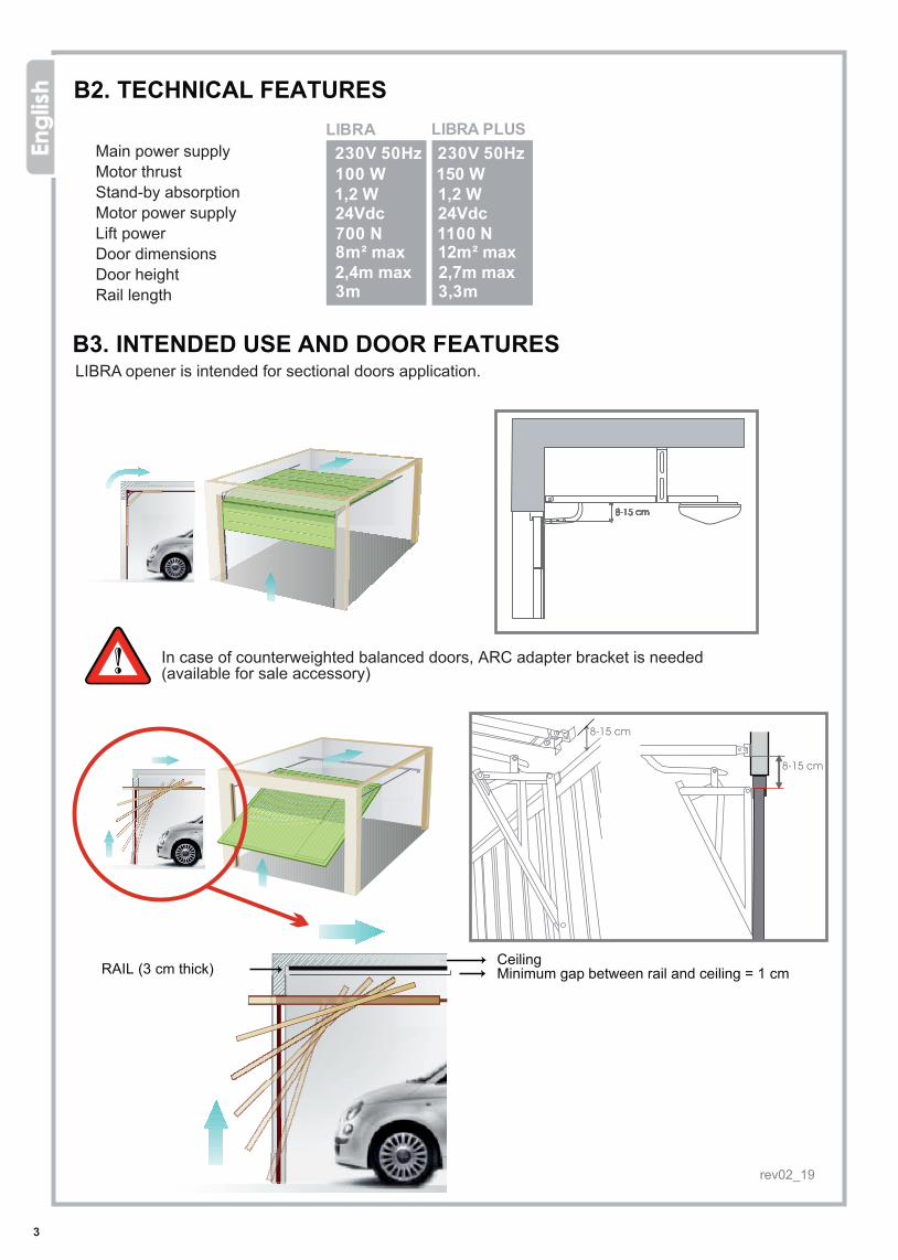
8m² max
230V 50Hz
1,2 W
2,4m max3m
3
100 W
700 N24Vdc
230V 50Hz
1,2 W
3,3m
12m² max
150 W
1100 N24Vdc
2,7m max
LIBRA LIBRA PLUS
B2. TECHNICAL FEATURES
RAIL (3 cm thick) CeilingMinimum gap between rail and ceiling = 1 cm
Main power supply Motor thrustStand-by absorptionMotor power supply Lift powerDoor dimensions Door heightRail length
B3. INTENDED USE AND DOOR FEATURESLIBRA opener is intended for sectional doors application.
In case of counterweighted balanced doors, ARC adapter bracket is needed (available for sale accessory)
B2. TECHNICAL DATA
Main power supplyMotor power supplyLifting power
Motor thrustStand-by absorption
Door dimensionsDoor heightRail length
B3. INTENDED USE, GARAGE DOOR TYPE AND APPLICATIONSLibra garage door opener is intended for sectional doors automation.
In case of counterweights balanced garage doors, an adapter bracket is needed.ARC adapter bracket can be purchased as optional accessory.
ceilingrail gauge = 3 cm minimum distance between
rail and ceiling = 1 cm
Luz de cortesía
B2. CARACTERÍSTICAS TÉCNICAS
Alimentación de redAlimentación motorFuerza de tracciónPotencia motor Potencia consumida en reposo Dimensiones puerta Altura puertaLongitud del raíl
B3. CARACTERÍSTICAS DE LA PUERTAEl motor es destinado para instalación de puertas de techo seccionales
Para puertas basculantes o debordantes es indispensable utilizar el accesorio opcional ARC - brazo adaptador.
TechoRaíl (espesor 3 cm) Distancia mínima en el puncto más alto (1 cm)
Tension principaleTension moteurForce en tractionPuissance moteurConsommation en stand-bySurface porteHauteur porteLongueur rail
B2.
B3. CARACTERISTIQUES DE LA PORTE ET CONSEILS D’INSTALLATIONL'automatisme pour porte de garage LIBRA est destiné à la motorisation de portes sectionelles.
En cas de porte de garage à contrepoids il est nécessaire installer aussi le bras adaptateur pour porte à contrepoids ARC, disponible en option.
plafondépaisseur rail = 3 cm distance minimum = 1 cm
(point de hauteur maxi)
LIFT UP LIFT UP plus
LIFT UP
rev02_19

4
C. SAFETY TIPS AND PRELIMINARY CHECKS
Before installing the automation, remove all unnecessary packaging and accessories;Check that door opens and closes easily and that mechanical parts are in good condition and correctly balanced;When installing make sure the manual release string is left less than 1,8 m length;Fixed start commands must be within the door area but safely far from moving parts, at minimum height of 1,5 m from ground. Visible permanent warnings of entrapment must be fitted.The emergency release system must be clearly permanently visible; Once installation is complete, make sure the opener is properly adjusted and reverses during closing if an obstacle is encountered at least 40 mm from ground;Make sure door does not obstruct public sidewalks or roads during operation;Once installation is completed, make sure the opener stops during opening if an obstacle is encountered. Put a 20 kg load in the centre of the door on the lower side to test the reaction of the system.
CAREFULLY FOLLOW MOUNTING INSTRUCTIONS.AN IMPROPER INSTALLATION MAY CAUSE SEVERE INJURIES!
C. RAIL ASSEMBLYC. MONTAJE DEL RAIL
1) Abrir el embalaje y disponer el rail al piso
2) Insertar los juntos dejando los topes a la vista
Tope
Junto
Tope Tope Tope
Junto
3) Utilizar una llave a tubo Ø 10 para atornillar la tuerca
4) Ajustar la distancia según el dibujo
rev02_19
5
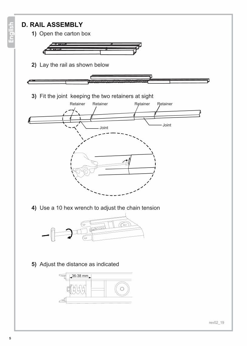
D. RAIL ASSEMBLY1) Open the carton box
2) Lay the rail as shown below
3) Fit the joint keeping the two retainers at sightRetainerRetainer RetainerRetainer
Joint Joint
4) Use a 10 hex wrench to adjust the chain tension
5) Adjust the distance as indicated
D. INSTALLATION
Junto
D. MONTAJE DEL EQUIPO
CUMPLIR CON TODAS LAS INSTRUCCIONES YA QUE PERSONAS Y OBJETOS PUEDEN SER PERJUDICADOS GRAVEMENTE.
Comprobar que la puerta abra y cierre facilmente sin fricciones y que los herrajes
El cable de desembrago manual debe ser facilmente alcanzable y estar a una altura
Instalar los comandos fijos cerca de la puerta pero suficientemente lejos de su rayo de
Colocar avisos bien visibles para señalizar el riesgo de quedar atrapados durante el
Bien señalizar el sistema de desembrago manual. Cuando la instalación esté terminada inicializar una maniobra para comprobar el correcto
de sentido si la puerta se topa con un obstáculo
Comprobar que el equipo impida o detenga el movimiento de apertura al cargar almenos inferior de la puerta.
estén propios
inferior a 1,8 m
funcionamiento y a una altura superior a 1,5m.
funcionamiento de la puerta.
funcionamiento del equipo incluído el cambiode 40 mm desde el suelo.
20 kg, colocandolos al centro del borde
HERRAMIENTAS NECESARIAS
D.
rev02_19
36-38 mm
12
3
4
1
2 3
456
78
9
9 10
11
136
66
613
14
121212 12
6
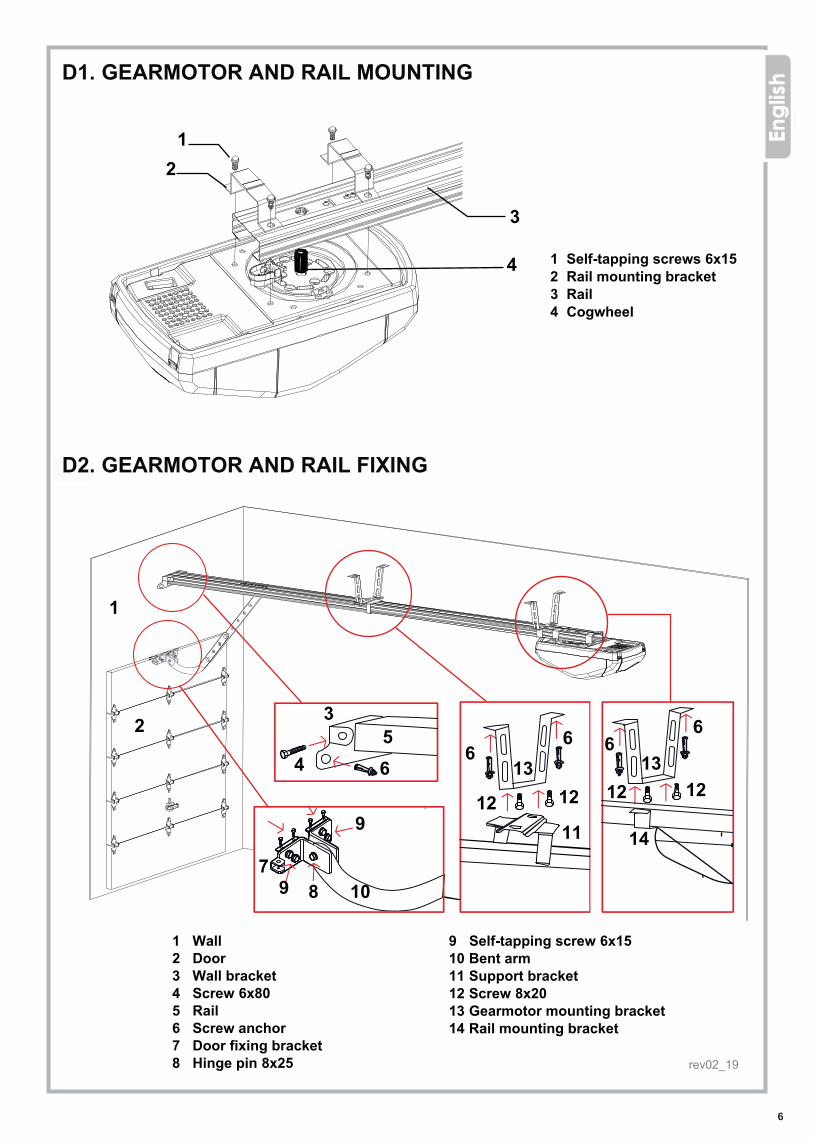
1 Self-tapping screws 6x15 2 Rail mounting bracket3 Rail4 Cogwheel
9 Self-tapping screw 6x1510 Bent arm11 Support bracket12 Screw 8x2013 Gearmotor mounting bracket 14 Rail mounting bracket
1 Wall2 Door3 Wall bracket4 Screw 6x805 Rail6 Screw anchor 7 Door fixing bracket8 Hinge pin 8x25
D1. GEARMOTOR AND RAIL MOUNTING
D2. GEARMOTOR AND RAIL FIXING
1 Driving screws 6x152 “U” bracket3 Rail4 Pinion
9 Driving screw 6x1510 Bent door arm11 Support bracket12 Screw 8x2013 Mounting bracket14 “U” bracket
1 Front wall2 Door3 Front wall fixing bracket4 Screw 6x805 Rail6 Rawlplug7 Door fixing bracket8 Inserted pin 8x25
D1. CONEXIÓN DEL MOTOR AL RAIL
1 Tornillos autorroscantes 6x152 Soporte “U”3 Raíl4 Piñon
D2. INSTALACIÓN DEL MOTOR Y DEL RAIL AL TECHO
1 Pared 2 Puerta3 Soporte dintel4 Tornillo 6x805 Raíl6 Anclaje a expansión 6x80
7 Soporte puerta Tirante de sujeción techo 8 Eje 8x259 Tornillo autorroscante 6x1510 Brazo curvo puerta11 Escuadra tirante12 Tornillo 8x20
1314 Soporte «U»
9 Vis autofilecteuse 6x1510 Bras courbe pour porte11 Étrier de support12 Vis 8x2013 Patte de soutien motorisation14 Patte à “U”
1 Linteau2 Porte3 Patte de fixation au linteau4 Vis 6x805 Rail6 Vis tamponnée7 Patte de fixation à la porte8 Cheville 8x25 rev02_19
7
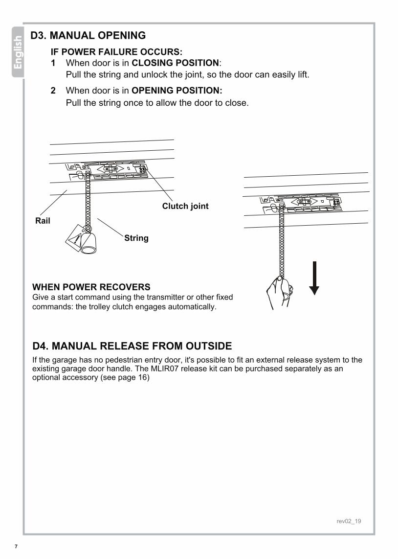
D3. MANUAL OPENINGIF POWER FAILURE OCCURS: 1 When door is in CLOSING POSITION: Pull the string and unlock the joint, so the door can easily lift.
2 When door is in OPENING POSITION: Pull the string once to allow the door to close.
String
Clutch jointRail
WHEN POWER RECOVERSGive a start command using the transmitter or other fixed commands: the trolley clutch engages automatically.
D4. MANUAL RELEASE FROM OUTSIDEIf the garage has no pedestrian entry door, it's possible to fit an external release system to the existing garage door handle. The MLIR07 release kit can be purchased separately as an optional accessory (see page 16)
D3. EMERGENCY RELEASE
In case of garage doors with one access only (doors with external opening handle), you may also consider the installation of a release system from outside.The external release kit MLIR07 can be purchased for this purpose as optional accessory (see pag.16)
D4. MANUAL RELEASE FROM OUTSIDE
D3. DESBLOQUEO MANUAL DE LA PUERTAEN CASO DE FALTA DE ALIMENTACIÓN
1. Si la puerta está CERRADA:Tirar la cuerda, desbloquear y abrir la puerta. 2. Si la puerta está ABIERTA: Solo tirar la cuerda una vez para cerrar la puerta.
Raíl
Cuerda
Embrague
CUANDO SE RESTABLEZCA EL SUMINISTRO ELÉCTRICOPulsar el mando o un dispositivo de apertura fijo: la fricción del tren de arrastre se embraga automáticamente.
Si el garaje no tiene otro acceso colocar un sistema de desbloqueo manual exterior conectado al tirador existiente. El kit de desbloqueo exterior MLIR07 es disponible como accesorio opcional (parráfo DESBLOQUEO MANUAL EXTERIOR).
D4. DESBLOQUEO MANUAL DESDE EL EXTERIOR
D3.
Si votre garage ne possède que un seul accès, vous pouvez envisager l'installation d'un systéme de deverrouillage relié à la poignée exterieure de la porte.Dans ce cas le kit pour débrayage de l'exterieur MLIR07 est disponible en achat comme accessoir otpionel (voir page 16)
D4. DÉBRAYAGE MANUEL DE L’EXTERIEUR
rev02_19

8
E1. SETTING THE LIMIT SWITCH IN OPENING
E2. SETTING THE LIMIT SWITCH IN CLOSING
E. PROGRAMMINGPress “P” and hold for 8 seconds, to start programming. Once adjustments are done, press “P” and hold for 8 seconds again to save the settings and gou out of the programming mode.
PRELIMINARY COMMISSIONINGa) Lock the clutch and gently move the door to closing position.b) Power the garage door opener: the courtesy light turns on, the display
shows a "0" rotating clockwise and the control unit "beeps" once.
Press “P” and hold for 8 seconds
The control unit beeps and shows “1”
Press “P”, “1” starts flashing
Press and hold “+” ...until the door reaches the desired opening position
Press “P” to save
Press “+” to set “2” Press and hold “-”...Press “P”, “2” starts flashing
...until the door reaches the desired closing position
Press “P” to save
E. PROGRAMACIÓNANTES DE EMPEZAR: 1) Embragar la fricción del tren de arrastre y cerrar suavemente la puerta 2) Alimentar, la luz se enciende, la central eléctronica hace un “ ” y en la pantalla beep sale “ ”. 0
Cuando la programación esté ultimada y la central no reciba comandos durante más de 2 minutos, todos los ajustes se pierden y vuelven a los valores de fábrica. Para hacer el reset quitar la alimentación y restaurarla.
E1. REGULACIÓN FINAL DE CARRERA EN APERTURA
Apretar en “ ” P8 segundos
La central hace un “ “ y visualiza “ ”beep 1
Pulsar “ ”, la pantalla Pparpadea “ ” 1
Apretar en “ ” +y mantener
La puerta abre hasta llegar a la apertura ideal
Pulsar “ ” para Pmemorizar
Apretar en “ ” -hasta ver “ ”2
Pulsar “ ”, la pantallaPparpadea “ ” 2
Apretar en “ ” y -mantener
La puerta abre hasta llegar al cierre
Pulsar “ ” para Pmemorizar
E2. REGULACIÓN FINAL DE CARRERA EN CIERRE
La con�guración ajustada se pierde si se utiliza para regular el �nal de carrera en cierre.
La con�guración ajustada se pierde si se utiliza para regular el �nal de carrera en abertura.
rev02_19
9
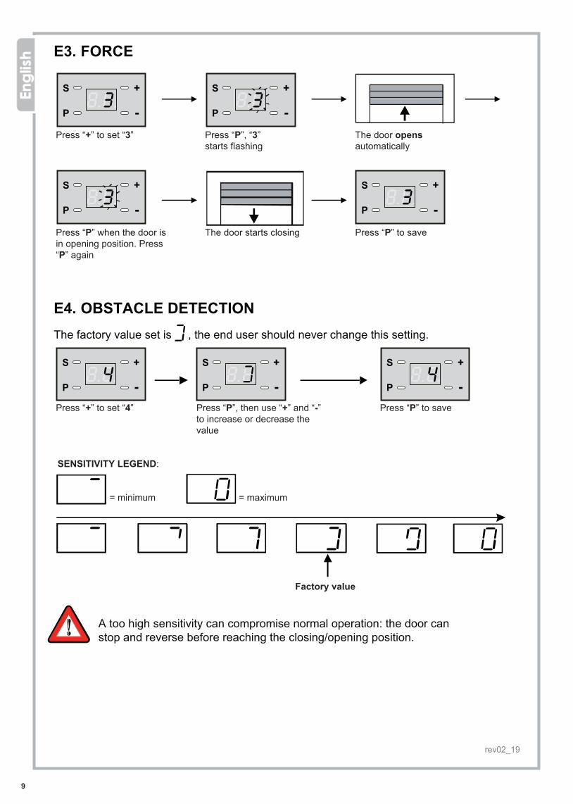
E3. FORCE
Press “+” to set “3” Press “P”, “3” starts flashing
The door opens automatically
Press “P” when the door is in opening position. Press “P” again
The door starts closing Press “P” to save
E4. OBSTACLE DETECTIONThe factory value set is , the end user should never change this setting.
Press “+” to set “4” Press “P”, then use “+” and “-” to increase or decrease the value
Press “P” to save
SENSITIVITY LEGEND:
= minimum = maximum
Factory value
A too high sensitivity can compromise normal operation: the door can stop and reverse before reaching the closing/opening position.
E4. PHOTOCELLS SETTING
This garage door opener is pre-set to be used alone but we recommend the installation of at least one set of safety photocells.To wire the photocells remove the existing jumper on connectors and follow wiring diagram. Press again to move further on the programming menu."-"
E3. REGULACIÓN DE FUERZA
Apretar en “ ” -hasta ver “ ”3
Pulsar “ ”, la pantalla Pparpadea “ ” 3
La puerta abre automáticamente
La puerta se detiene. Apretar en “ ” dos vecesP
La puerta cierra Pulsar “ ” para Pmemorizar
Ultimado el ciclo de maniobra, apretar en “ ”, la pantalla visualiza “ ”, + 1pulsar “ ” hasta ver “ ” para salir de la programación.P 0
E4. FOTOCÉLULAS
Apretar en “ ” hasta -ver “ ”4
Pulsar “ , la pantallaP”parpadea“ ” 1
Apretar en “ ”, la central +hace un “ ”. Las fotocélulas beep
habilitadashan sido
Apretar en “ ” la central -hace un doble “ ”.beepLas fotocélulas han sido inhabilitadas.
Pulsar “ ” para memorizar.P
Habilitar esta función solo si se desea montar fotocélulas.Para conectar las fotocélulas, quite el puente y siga el esquema de conexión.Para desactivarlas siga la procedura
E3. REGLAGE DE LA FORCE MOTEUR
E4. PROGRAMMATION DES PHOTOCELLULES
Cette motorisation est réglée d'usine pour une mise en service immediate, toutefois
rev02_19

10
Preimpostazione di fabbrica
E5. OPENING SPEEDThe factory value set is “2”, setting “1” the opening speed slightly increases.
Press “+” to set “5” Press “P” and use “+” and “-” to change the value
Press “P” to save
E6. DOOR OPENED ALERTThis function beeps within 10 minutes if the door is left open. The factory setting is "0" (function deactivated); to activate it, set “1”.
Press “+” o “-” to set “6” Press “P” and use “+” e “-” to activate or deactivate the function
Press “P” to save
La puerta cierra
E5. TEST FOTOCÉLULASNota: Hacer el test si hay fotocélulas.soloPara hacer el test no es necesario salir de la programación.
Apretar en “ ” -hasta ver “ ”5
Pulsar “ ”, la pantalla Pparpadea “ ” 5
La puerta abre
Cortar el rayo de las fotocélulas.“ ” confirma Aque el conexionado está bien.Si “ ” no sale, comprobar el conexionado. A
Pulsar “ ” para Pmemorizar
E6. REGULACIÓN FUNCIÓN ANTIAPLASTAMIENTODe fábrica viene con un valor y se requiere mantenerlo posiblemente sin alteraciones.
Apretar en “ ” -hasta ver “ ”6
Pulsar “ “,salePApretar en “ ” +y bajar o subir el nivel de sensibilidad
Pulsar “ ” para Pmemorizar
SENSIBILIDAD: = POCO SENSIBLE = MUY SENSIBLE
Valor de fábrica
Si se pone un valor demasiado alto, entonces demasiado sensible, la puerta puede trabajar de forma incorrecta (p. ej: La puerta invierte el recorrido).
rev02_19
11
0
2
1
4
3
5
7
6
8
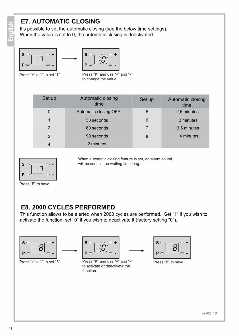
E7. AUTOMATIC CLOSINGIt's possible to set the automatic closing (see the below time settings).When the value is set to 0, the automatic closing is deactivated.
Press “+” o “-” to set “7” Press “P” and use “+” and “-” to change the value
Set up Automatic closing time
Automatic closing OFF
30 seconds
60 seconds
90 seconds
2 minutes
2,5 minutes
3 minutes
3,5 minutes
4 minutes
When automatic closing feature is set, an alarm sound will be sent all the waiting time long.
Press “P” to save
E8. 2000 CYCLES PERFORMEDThis function allows to be alerted when 2000 cycles are performed. Set “1” if you wish to activate the function, set “0” if you wish to deactivate it (factory setting "0").
Press “+” o “-” to set “8” Press “P” and use “+” and “-” to activate or deactivate the function
Press “P” to save
E7. REGULACIÓN FUNCIÓN ALARMA PUERTA ABIERTA De fábrica la función viene inhabilitada “OFF”.
Apretar en “ ” -hasta ver “ ”7
Pulsar “ ”P Pulsar “+” para habilitarinhabilitar
Pulsar “P” para memorizar
Pulsar “-” para
E8. REGULACIÓN CIERRE AUTOMÁTICODe fábrica la función viene inhabilitada.
Apretar en “ ” -hasta ver “ ”8
Pulsar “ ” hasta Pver “ ” y habilitar0
Apretar en “ ” hasta ver+“ ” y habilitar el tiempo1de cierre
Regular el tiempo de cierre automático según el esquema siguiente: por ejemplo 8 corresponde a 240 segundos y es el tiempo máximo que se puede ajustar.
Pulsar “P” para memorizar
Set up Automatic closing time
rev02_19
12
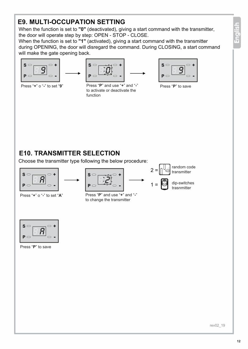
Press “+” o “-” to set “9” Press “P” and use “+” and “-” to activate or deactivate the function
Press “P” to save
Press “+” o “-” to set “A” Press “P” and use “+” and “-” to change the transmitter
Press “P” to save
E9. MULTI-OCCUPATION SETTINGWhen the function is set to "0" (deactivated), giving a start command with the transmitter, the door will operate step by step: OPEN - STOP - CLOSE. When the function is set to "1" (activated), giving a start command with the transmitter during OPENING, the door will disregard the command. During CLOSING, a start command will make the gate opening back.
E10. TRANSMITTER SELECTIONChoose the transmitter type following the below procedure:
RADIO TRANSMITTERS SELECTIONPlease follow this procedure to select the radio transmitter you are using:
Press "P", the displayshows the model ofradio transmitter selected
In case press "+" or "-" to change the selection of the radio transmitter model
Shows "2"=
Shows "1"=
random code radiotransmitter model
radio transmitter withdip-switches
Press "-" key to select "A"
Press "P" to save the settings
E9. HABILITACIÓN CONTADOR DE MANIOBRASDe fábrica la función viene inhabilitada.Para habilitar la función al alcanzar los 2000 ciclos:
Apretar en “ ” -hasta ver “ ”9
Pulsar “ ”,sale “ ”P 00 = función desactivada
Apretar en “ ”, sale “ ”+ 11 = función activada
Apretar en “ “ -sale “ ”=0 función desactivada
Pulsar “ ” para Pmemorizar
Para apagar la alarma quitar la alimentación y restaurarla.
Eligir el tipo de mando según la procedura siguiente:
E10. SELECCIÓN DEL MANDO
Pulsar ” para “Pvisualizar el tipo de mando
Apretar en “+” o “-“ para seleccionar el tipo de mando
Apretar en “ ” -hasta ver “ ”A
Pulsar “ ” para Pmemorizar
E11. MEMORIZACIÓN DE AJUSTES
Pulsar ” y apretar“P8 segundos
Apretar en “ ” +hasta ver “ ”1
Sale “ ” = operación 0exitosa
Es indispensable memorizar los ajustes según la procedura arriba. Caso contrario se perderán.
"2"=
"1"=
mando codígo fijo
mando con dip-switches
SELECTION DE LA TELECOMMANDESélectionner le modèle de télécommande utilisée par la procédure suivante:
Pressez "P": l’écranaffiche le modèle detélécommande sélectionnée
Affiche "2"=Affiche "1"=
télécommande à codesrandom télécommande àdip-switches
Pressez "-" pourfaire apparaître "A"
Si nécessaire presser "+" ou "-" pourchanger la télécommande sélectionnée
Pressez "P" poursauvegarder la sélection
A
B
C
Appare "2"=Appare "1"=
telecomando a codicerandom MYKEYtelecomando adip-switches TX4334A
B
C
Appare "2"=Appare "1"=
telecomando a codicerandom EXCITEtelecomando adip-switches PILOT
rev02_19
random codetransmitter
dip-switchestrasnmitter
A
B
C
13
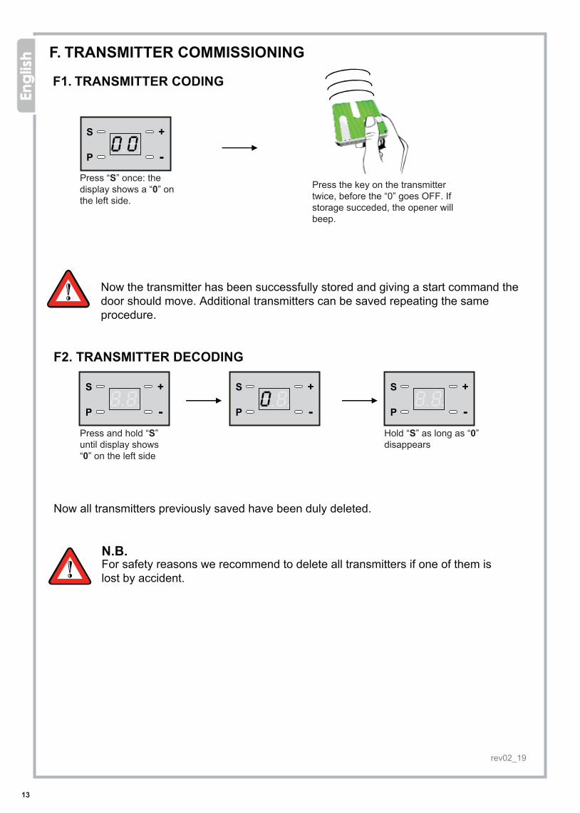
F. TRANSMITTER COMMISSIONING
F1. TRANSMITTER CODING
F2. TRANSMITTER DECODING
Press “S” once: the display shows a “0” on the left side.
Now the transmitter has been successfully stored and giving a start command the door should move. Additional transmitters can be saved repeating the same procedure.
Press and hold “S” until display shows “0” on the left side
Hold “S” as long as “0” disappears
Now all transmitters previously saved have been duly deleted.
N.B.For safety reasons we recommend to delete all transmitters if one of them is lost by accident.
Once the radio code has been correctly stored, you will hear a "beep".
F. MEMORIZACIÓN DE MANDOSF1. MEMORIZACIÓN CÓDIGOS RADIO
Apretar en “ ” S en la hasta ver “ ”0
izquierda de la pantalla
Pulsar el mando 2 veces antes que “ ”0desaparezca. En caso de éxito seguirá un “ ”.beep
El mando ha sido memorizado. Inicializar una maniobra de apertura. Si la puerta abre,otros mandos pueden ser memorizados.
F2. BORRADO DE MANDOS
Apretar en “ ” hasta Sver “ ” en la izquierda 0de la pantalla
Apretar en “ ” hasta queS “” desaparezca0
Si se pierde aun solo mando es recommendable borrar todos los codígos memorizados.
Pressez un bouton de la télécommande radio deux fois avant que le ‘0' disparaît de l’écran.A la mémorisation du code de la télécommande vous entendrez un "bip".
Press the key on the transmitter twice, before the “0” goes OFF. If storage succeded, the opener will beep.
rev02_19

14
-
-BB
U+
AC
24VM
OT-G
ND
+D
ISPLAYE-LO
CK
STAN
DB
YH
OLZER
TRIP-SW
LIGH
T
WIRING DIAGRAM
START CABLED COMMANDSBLINKER
AERIAL WIRE PHOTOCELLOR SAFETY EDGE (N.C. contacts)
(FA
CTO
RY
WIR
ING
)
Mic
rosw
itch
plug
Flas
hing
Lig
htou
tput
Enco
der
plug
G.ESQUEMA DE CONEXIÓNSa
lida
luz
inte
rmite
nte
Alim
enta
ción
trans
form
ador
Entra
datra
nsfo
rmad
or
Luz
de
cort
esía
RED
230V
Salid
atra
nsfo
rmad
orCo
nexi
ónde
tier
raEn
trad
am
otor
Cone
xión
pant
alla
Foto
célu
las
Con
tact
ofo
tocé
lula
sST
ART
Sort
ieCl
igno
tant
Bor
nes
pour
mic
roBorn
espo
ur e
ncod
er
Réc
epte
ur
rev02_19
15
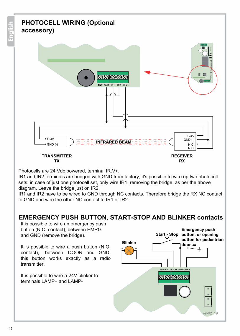
PHOTOCELL WIRING (Optional accessory)
TRANSMITTERTX
RECEIVERRX
INFRARED BEAM
Photocells are 24 Vdc powered, terminal IR.V+.IR1 and IR2 terminals are bridged with GND from factory; it's possible to wire up two photocell sets: in case of just one photocell set, only wire IR1, removing the bridge, as per the above diagram. Leave the bridge just on IR2.IR1 and IR2 have to be wired to GND through NC contacts. Therefore bridge the RX NC contact to GND and wire the other NC contact to IR1 or IR2.
EMERGENCY PUSH BUTTON, START-STOP AND BLINKER contactsIt is possible to wire an emergency push button (N.C. contact), between EMRG and GND (remove the bridge).
It is possible to wire a push button (N.O. contact), between DOOR and GND; this button works exactly as a radio transmitter.
It is possible to wire a 24V blinker to terminals LAMP+ and LAMP-
Blinker
Start - StopEmergency push button, or opening button for pedestrian door
CONEXIÓN DE FOTOCÉLULAS(Accesorios opcionales)
Radar fotocélulas
La interrupción del rayo de fotocélulas en cierre detiene de inmediato el movimiento de la puerta. En apertura no causa ningun efecto.
Radar photocellules
rev02_19
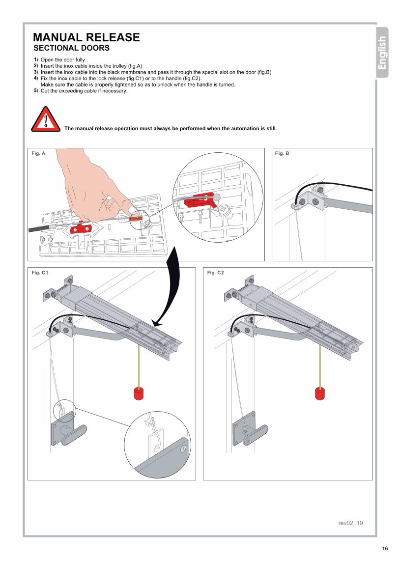
Fig. A Fig. B
Fig. C1 Fig. C2
16
1) 2) 3) 4)
5)
MANUAL RELEASESECTIONAL DOORS
Open the door fully.Insert the inox cable inside the trolley (fig.A)Insert the inox cable into the black membrane and pass it through the special slot on the door (fig.B)Fix the inox cable to the lock release (fig.C1) or to the handle (fig.C2). Make sure the cable is properly tightened so as to unlock when the handle is turned.Cut the exceeding cable if necessary.
The manual release operation must always be performed when the automation is still.
MANUAL RELEASE KITDESBLOQUEO MANUAL EXTERIORPUERTAS SECCIONALES1) Abrir la puerta por completo2) (figIntroducir el cable en acero en su alojamiento dentro del tren de arrastre .A ).3) (figInsertar el cable en la vaina de protección y pasarlo por el agujero del soporte de fijación puerta . )B4) Fijar e l cable de acero al desbloqueo de la cerradura (fig. ) o al tirador realizando un pequeño agujero en la empuñadura (fig. )C C25) Cortar eventualmente el cable en exceso
ATENCIÓN: Desbloquear manualmente solo cuando el equipo no esté en función
KIT DE DÉBRAYAGE MANUEL
rev02_19

Manuale di installazioneFig. A Fig. B
Fig. C Fig. D1 Fig. D2
17
1) 2) 3)
4) 5)6)
OVERHEAD DOORS (Adapter PARC01 available as optional)
Open the door fully.Insert the inox cable inside the trolley (fig.A)Cut the breaket (useless in case of overhead doors) as shown in fig. B and fix it on the door, beside the adapter.Insert the inox cable into the black membrane and pass it through the special slot on the door (fig.C)Fix the inox cable to the lock release (fig.D1) or to the handle (fig.D2). Make sure the cable is properly tightened so as to unlock when the handle is turned.Cut the exceeding cable if necessary.
The manual release operation must always be performed when the automation is still.
COUNTERWEIGHTED doors (with adaptor arm PARC01)1) Open the door wide.2) Place the thin steel cable with end-ball in the pulling trolley (Fig. A).3) Cut the anchoring door bracket (not used in case of counterweights balance door with adaptor arm) as shown in Fig. B
and fix the bracket on the door beside the adapter arm.4) Thread the steel cable into the rubber sheath and insert it in the eyelets of the anchoring door bracket (Fig. C).5) Fasten the steel cable directly to the lock catch (Fig. D1) or to the door’s handle by piercing it (Fig. D2). Make sure that the steel cable’s tension is suitable to operate the release when twisting the handle.6) In case, cut the extra cable away.
Perform the manual release operation only when the door is not moving.
PUERTAS BASCULANTES (con adaptador opcional PARC01)1) Abrir la puerta por completo2) (figIntroducir el cable en acero en su alojamiento dentro del tren de arrastre . )A3) Cortar el soporte de fijación puerta segun la fig. y fijarlo en la puerta a lado del adaptadorB4) Insertar el cable en la vaina de protección y pasarlo por e l agujero del soporte de fijación puerta (fig. )C
Fijar el cable de acero al desbloqueo de la cerradura (fig. C) o al tirador realizando un pequeño agujero en la empuñadura (fig. D2). 5)
Cortar e ventualmente el cable en exceso6)El cable debe tener la tensión correcta para accionar el t irador de desbloqueo.
ATENCIÓN:
Desbloquear manualmente solo cuando el equipo no esté en función
Portes à CONTREPOIDS (avec bras adaptateur PARC01)1) Ouvrir complètement la porte.2) Positionner le câble en acier en acier avec la petite boule dans le chariot d’entraînement (Fig. A).3) Découper la patte de fixation à la porte (pas utilisée dans le cas de portes à contrepoids avec bras adaptateur)
comme indiqué (Fig. B) et fixer la patte sur la porte à coté du bras adaptateur. 4) Introduire le câble en acier dans la gaine et le faire passer dans les œillets de la patte de fixation à la porte (Fig. C).5) Fixer le câble en acier directement au loquet de la serrure (Fig. D1) ou bien à la poignée de la porte en la perçant (Fig. D2). Assurez-vous que le câble soit suffisamment en tension pour déclencher le déverrouillage lorsqu’on tourne la poignée.6) Si nécessaire, couper le câble superflu.
Ne pas débrayer la porte manuellement pendant le mouvement.
rev02_19

Fig.D Fig.E
Fig.F Fig.G Fig.H
Fig.I Fig.L Fig.M
18
1)
2) 3) 4) 5) 6)
7) 8)
9)
drive arm
ARM ADAPTER FOR OVERHEAD GARAGE DOORS OPTIONAL ACCESSORY AVAILABLE FOR SALE
The ARC adapter arm is designed for counterweight spring overhead doors (fig.D) and looks like fig.E.
DRIVE ARM REPLACEMENTPrepare the trolley for drive arm replacement (fig.F).The drive arm is supplied with the automation LIBRA.Unscrew the 5 screws that fix the trolley (fig.G).The trolley when opened looks like fig.H. The drive arm is placed in the highlighted joint. To remove it, simply lift it from the seat. Make sure the string for manual release is fitted inside the gap (fig.I)Place the boomerang bracket provided witht the arm adapter, leaving the string through as shown in fig.LTighten the 5 screws and fix the bracket to the trolley (fig.M)
ARC ADAPTER ARM MOUNTINGFit the adapter arm to the boomerang bracket (fig.N)Fix the adapter arm ARC in the center of the door, with the upper edge of the fixing plate at the height of the upper edge of the plate.
Fix the lower side of the fixing plate to the door frame (fig.O). Check the frame is strong enough, otherwise proper support must be provided.
Check the gap between the upper edge of the door and the rail of the automation is between 8 and 15 cm (fig.P)
Programm the door operator and check the correct operation of the system and the arm.
boomerang bracket
ARC arm adapter
ADAPTER BRACKET FOR COUNTERWEIGHT-BALANCED DOORS
The use of ARC adapter is recommended in case of counterweight-balanced or spring-balanced garage doors (A). The adapter is supplied ready to install as shown in the picture (B):
HOW TO REPLACE THE ORIGINAL STRAIGHT PULLING BRACKET WITH BOOMERANG BRACKET1) Slide the driving trolley gently so that you can easily remove the straight pulling bracket originally supplied with the LIBRA opener (C). 2) Unscrew the 5 fixing screws of the trolley (fig. D).3) Open the trolley as shown in fig. E. The pulling bracket is fitted in the trolley. You just need to lift it to remove it from its slot.4) Before inserting the boomerang bracket, make sure that the release strap get properly into the hollow (F).5) Insert the boomerang bracket, the release strap shall appear on the trolley as shown in the picture (G).6) Fix the boomerang bracket to the driving trolley using the 5 available screws (H).
HOW TO FIX THE ADAPTER ARC7) Close the door and join the ARC adapter together with the boomerang bracket (I).8) Fix the ARC adapter in the middle of the door, with the upper edge of the fixing plate aligned with the door’s upper limit. Fix the
lower part of the plate on the door’s frame (K). Make sure that frame is sturdy enough to bear the weight of the adapter, if not please provide the door with a suitable support for the bracket fixing.
9) Perform a standard opening-closing cycle and check that both door and adapter move properly and smoothly.
Make sure that distance between the upper edge of the door and the opener’s rail remains between a 8 to 15 cm range.
INSTALLATION GUIDELINES FOR USE WITH LIBRA GARAGE DOOR OPENER
provide
ARC adapter
boomerang bracket
straight pulling bracket
BRAZO DE TRACCIÓN PARA PUERTAS BASCULANTESEl brazo de tracción ARC (fig. E) e stá diseñado para puertas basculantes con contrapesos o resortes (fig. D).
SUSTITUCIÓN DEL BRAZO DE TRACCIÓN:
1) F Preparar el tren de arrastre para sustituir el brazo de tracción (fig. )2) G Desatornillar los 5 tornillos que aseguran el tren (fig. )3) HEl brazo de tracción es ubicado dentro del tren de arrastre (fig. ). Para sacarlo simplemente levantarlo4) I Asegurarse de que la cuerda de desbloqueo esté insertada en el acanalado (fig.)5) LColocar el soporte a bumerán suministrado junto al brazo de tracción dejando pasar la cuerda segun el dibujo (fig. ).6) MAtornillar los 5 tornillos y fijar el soporte al tren (fig. ).
FIJACIÓN DEL BRAZO DE TRACCION “ARC”:7) NConectar el brazo al soporte a bumerán (fig. )8) Fijar el brazo ARC al centro de la puerta. El borde superior del soporte deberá colocarse a la altu ra del borde superior de la puerta.
Fijar la parte inferior del soporte al marco de la puerta (fig. ). Comprobar que la estructura de la puerta sea robusta de otra manera renforzarla.O
ATENCIÓN: Entre el raíl y el borde superior de la puerta debe pasar una distancia entre 8 y 15 cm (fig. )P
9) Inicializar una maniobra completa y comprabar el correcto funcionamiento del equipo.
(Accesorios opcionales)
Soporte a bumerán
Brazo adaptador
Brazo de tracción
LIFT UP
rev02_19

Fig. N Fig. O
19
Fig. P
MAINTENANCEa) The LIBRA and LIBRA PLUS automation models for garage doors are low environmental
impact products. Under normal use, just a minimal maintenance is required.b) Before starting the operation check that drive sytem slides fluently (unlock the trolley
clutch, open and close the door manually).c) Periodically check that door opens and closes at the correct heights and that springs have
sufficient thrust to lift the door. Lubricate mechanical gears regularly if necessary.
If power failure occurs the door will behave as follows:
During blackout the door stops
When power is restored, give a start command with the transmitter.The door starts closing.
Reaches the limit switch in closing and stops.
In case of power cut, the door can be opened and closed manually, just unlocking the trolley clutch (pag.7).
MANTENIMIENTO a) Los equipos LIBRA y LIBRA PLUS están diseñados con un bajo impacto ambiental y por un uso residencial necesitan de muy poco mantenimiento. b) Antes de poner el equipo en marcha comprobar que el sistema de tracción deslize facilmente (desenganchar la fricción del tren de arrastre, entonces abrir y cerrar la puerta manualmente) c) Comprobar periódicamente que la puerta abra y cierre conformemente las alturas ajustadas y que los resortes siempre empurren suficientemente para levantar la puerta. Lubricar regularmente los engranajes mécanicos.
INTERRUPCIÓN DEL SUMINISTRO ELÉCTRICOEn caso de falta de corriente la puerta actua de la manera siguiente:
1. La puerta se detiene 2. Cuando el suministro se restaure apretar en el mando, la puerta cierra
3. Según los ajustes la puerta llega al final de carrera en cierre y se detiene
En caso de falta de corriente, es posible desbloquear la puerta desenganchando la fricción del tren de arrastre (parráfo D3 y D4)
LIFT UP LIFT UP PLUS
rev02_19

20
Display Fault
THE AUTOMATION DOES NOT WORK, THE DISPLAY IS OFF
THE DOOR DOES NOT MOVE
THE CHAIN TURNS BUT THE DOOR DOES NOT MOVE
THE ALARM KEEPS ON SOUNDING
THE DOOR DOES NOT OPEN NOR CLOSES, STUCKS WHEN CLOSING
THE DOOR DOESNOT WORK PROPERLY
THE DOOR DOES NOT MOVE OR DOES NOT COMPLETE THE CYCLE
THE DOOR DOES NOT MOVE, OR STOPS, OR REVERSES
THE DOOR STREAKS WHEN OPERATING
THE CHAIN LOSTTENSION AND IT'SNOISY
THE DOOR REMAINS OPENED
TROUBLE SHOOTINGThe control unit is integrated with self-diagnostic feature. Any possible faults will be detected and alerted through the display. Here below the list of most common faults and solutions.
Cause
• Check the power supply.
• Fuses can be possibly burnt.
• No transmitter has been stored
• Check the transmitter battery charge
• The trolley's clutch may be unlocked
• The chain has come out the cogwheel
Solution
Check the power supply.
Replace the fuses.
Replace the battery.
Lock the clutch (p.7)
Properly lubricate the part between the rail and the clutch.• Friction between rail and clutch due to waste
Fix the bolt properly on the spring, hold the chain in place and lubricate it.
• Chain tension reduction due to extendeduse without regular lubrication
Follow the installation instructions (p. 5)
Check photocells wiring (p. 15)• Incorrect photocell wiring
Check the safety microswitch is not crushed.Release the microswitch that may have been trapped.
• Crushed safety microswitch
• Incorrect photocell wiring
• Permanent obstacle within the photocellarea
Check photocell operation and wiring again (p.15)
Clear the photocell area.
• Microswitch operating - simple warning
• Possible humidity traces in the electronicsand wires
• Possible oxide traces in motor's wires• Photocell short circuit• Fautly microswitch
Remove humidity (qualified personnel only) Check motor's wiring
Check photocell's wiring (p.15) Check microswitch' wiring
• Faulty door frame or incorrectly installed• Faulty motor or motor not wired• Faulty encoder or not wired
Check the mechanical conditions of the door.Check the adjustment of springs and counterweights. Adjust the force settings, p.9 E3.
Reposition the chain on the cogwheel.
• 2000 cycles have been performed
Set limit switches again (p. 8).• Unproper setting
Adjust counterweights and springs.• Incorrect balancing of counterweights orsprings
Follow the installation instructions (p. 18)• Incorrect installation of the boomerangbracket (for overhead doors only)
• The door is left opened since a while and thealarm function is activated
Close the door.Switch the power off and then on again.
Store a new remote control.Incorrect transmitter selection, review procedure.
• The distance of the tension springhas not been adjusted
TROUBLESHOOTING
Error Causa SoluciónEl equipo no funciona Llamar a un instalador-Falta de alimentación
-Fusible quemadoLa puerta no se mueve
El alcance del mando es debil Batería débil
-El mando no ha sido memorizado-Batería agotada
-Memorizar el mando-Sustituir la bateria
Sustituir la batería
La alarma sigue sonando
La puerta abre o cierra de forma incorrecta La puerta actua de forma incorrecta y la pantalla visualiza “H”
-La puerta se detuvo abierta demasiado tiempo
Llamar a un instalador y reparar el resorte. Ajustar el nivel antiaplastamiento hasta que “F” desaparezca
Cerrar la puertaQuitar la alimentación y restaurarla-Los 2000 ciclos han sido alcanzados
-Batería agotada
Ajuste errado Reprogramar la central
Problema de humedad en la centraleléctronica
Llamar a un instalador y secar lacentral
La puerta se detiene de repente actua a saltos y la pantalla visualiza “F”
-El resorte de tracción se tuerce-La puerta detuvo un obstáculo-Alimentación instable
La puerta chirria al abrirse ocerrarse
-Roce entre el rail y la fricción debido al desgaste
Lubricar correctamente o encerar la parte entreel rail y la fricción
La cadena hace ruido -Aflojamiento de la cadena debido a la utilización prolongada sin lubricación adecuada
Fijar correctamente el perno sobre el resorte, mantener la cadena en su sitio y lubricarla
Peligro de descarga eléctrica. Sólo un técnico profesional puede intervenir en los cables y componentes del cuadro eléctronico.Risque d'électrocution, seul un professionnel peut intervenir sur la carte rev02_19

rev02_19
EU DECLARATION OF CONFORMITY
The manufacturer:
address:
declares that
The product type: models: and accessories:
PROTECO S.r.l.
Via Neive, 77 – 12050 Castagnito (CN) – ITALIA
LIBRA garage door openerLIBRA, LIBRA PlusSK3000, SK3300, MYKEY/TX4334
is built to be integrated into a machine or to be assembled with other machinery to create a machine under provisions of 2006/42/EC Machinery Directive.
It complies with the essential requirements of EU directives:
2014/30/UE (EMC)2014/53/UE (RED)RoHS2 2011/65/CE2014/35/UE (LVD)
The product also complies, for the applicable parts, to the following directives and standards:EN12453, EN12604EN55014-1, EN55014-2, EN61000-6-1, EN61000-6-3EN 60335-1, EN 60335-2-103, EN 60335-2-95
The manufacturer declares that the commissioning of the machinery is not permitted until the machine,which this product is incorporated into, has been identified and declared conformantto the 2006/42/EC Machinery directive.
Castagnito, May 27 th 2019
Marco GalloManaging Director
This compliance declaration combines the content of separate compliance declarations for any product mentioned; a copy of the original compliance declaration of each product can be asked anytime to PROTECO Srl.

DISPOSAL
Do not dispose of in nature
Some components may contain hazardous waste.They must, thus, be removed and turned into licensed firms for their disposal.Before acting always check the local laws on the matter.
22
0173/210132
346/4192300WhatsApp
CHIAMACI!Il nostro servizio assistenza è a tua disposizione per
qualsiasi chiarimento sul prodotto, sull’installazione o sulla garanzia:
Per qualsiasi chiarimento sul prodotto,
assistenza durante l’installazione e informazioni sulla garanzia
GRAZIE PER AVER SCELTO Euromatic!
Il nostro Servizio Assistenza è a tua disposizione Lunedì-Venerdi, 8.30-12.00 13.30-17.00
CHIAMACI
Per un servizio più efficiente, prima di contattarci fai in modo di:- trovarti in prossimità dell’automazione
- avere a portata di mano il manuale di installazione e uso
0173/210132
346/4192300WhatsApp
rev02_19
Proteco srlVia Neive 77 12050 Castagnito+39 0173 210132 www.proteco.net
rev02_19