Leveling Barometric Trigonometric and Spirit - Forgotten Books
172
-
Upload
khangminh22 -
Category
Documents
-
view
1 -
download
0
Transcript of Leveling Barometric Trigonometric and Spirit - Forgotten Books


lomo. Boards. Price 60 Contl '
EMh.
Amp lyWh am when th e Subj ec t Demand s .
N6 . k—CHIMNEYS FOR FURNACES AND STEAM-BOILERS. By R. Armstrong, C .E . 3d Amer ican ed .
Revised andgartly rewritten, w ith an Ap ndix
onTheory of himneyDraught, by F. E . Ide M.E .
No . 2.—STEAM—BOILER EXPLOSIONS. By Zemh Colburn .
New edition, revised by Prof. R . H . Thurston .Wo . 3 .— PRACTICAL DESIGNING OF RETAINING-WALLS.
Fourth edltion . By Prof.W. Cain .
No . 4.— PROPORTIONS OF PINS USED IN BRIDGES" By
Chas . E . Bender,C .E . 2d edition, with appendix.
BUILDINGS. By W.F. Butler.
Second ec ition, re~edited and enlarged by JamesL. Green leaf. C. E .
No. 6.—ON THE DESIGNING AND CONSTRUCTION OF
STORAGE RESERVOIRS. ByArthur Jacob,A.
B . Second edition, revised,Wi th additions by E.
Sherman Gould .
NO. 7.—SURCHARGED ANDDIFFERENT FORMS OF RETvAINING-WALLS. By James S . Tate, C .E .
No . 8.-A TREATISE ON THE COMPOUND ENGINE . ByJohn Turnbull, jun . Second ed ition,
revised byProf . S. W. Robinson .
NO. 9.-A TREATISE ON FUEL. By Arthur V. Abbott,
C .E . Founded on the originaltreatise of C. William S iemens, D .C .L.
0
No. 10.—COMPOUND ENGINES. Trans lated from the
French of A. Mallet . Second edi tion ,revised,
with resu lts of American Practice by Richard H.
Buel, C .E .
No. Ila-THEORY or ARCHES. By Prof. w.Allan.
No. 12.-THEORY OF VOUSSOIR ARCHES . Prof. W .
2‘ Cain . Second ed ition, revised and en arged .
No. m—GASES MET WITH IN COAL-MINES. By J. J.Atkinson . Third ed ition, revised and enlargedby Edward B . Wil l iams , jun .
h H‘RICTION OF AIR IN MINES. By J. J. Atkinson .
Second Am erican edition .
No . M KEWARCHES . By Prof. E .W. Hyde,C .E . Illustr .
No . 16 .—A GRAPHIC ME THOD FOR SOLVING CERTAIN
QUESTIONS IN ARITHMETIC OR ALGEBRA.
By Prof. G . L. Vose .
—WATER ANDWATER SUPPLY. By Prof . W . H.
Corfleld of the Un ivers ity Co llege, London.
Second American ed ition .
m—SEWERAGE AND SEWAGE PURIFICATION. By
M. N. Baker, Associate Ed ito r Engineeri ng News.”
Ne. 19.-STRENGTH OF BEAMS UNDER TRANSVERSE
LOADS . By Prof. W. Allan, author of “Theoryof Arches .
” Second ed it ion , revised .
No. 20.— BRID‘GE AND TUNNEL CENTRES . By John B.
McMas ter, C .E . Sec ond ed ition .
up. si .-SAFETY VALVES . Second Edition. By RichardH. Buel, C .E .
Ito. zz.—HIGH MASONRY DAMS.
’
By E . Sherman Gould,M. Am . Soc. C . E .
No . 23 .—THE FATIGUE OF METALS UNDER REPEATEDSTRAINS. With various Tables of Results andExperiments . From the German of Prof . Ludwigi
ngenburgh, with a Preface by S . H . Shreve,No. 24.— A PRACTICAL TREATISE ON THE TEETH OF
WHEELS . By Prof. S. W. Robinson . Secondedition, revised .
No . 25 .— ON THE THEORY AND CALCULATION OF CON
TINUOUS BRIDGES . ByR .M.Wilcox,Ph . D.
zit—PRACTICAL TREATISE ON THE PROPERTIESggdcog
'
filNUOUS BRIDGES. By Char les
n er,No . 27.-ON BOILER INCRUSTATION ANDCORROSION.
ByF. J . Rowan . New Ed . Rev. by F. E . 108 11.
No . 28 .—TRANSMISSION OF POWER BY WIRE ROPES.
Sec ond edit ion . By Albert W . Stahl,U .S .N.
No . 29.—STEAMINJECTORS. Translated from the French
of M . Leon Pochet.No . 30.
—TERRESTRIAL‘MAGNETISMAND THE MAG
NETISM OF IRON VESSELS. By Prof. Fairman Rogers .
No . 31 .—THE SANITARY CONDITION OF DWELLINGHOUSES IN -TOWN AND COUNTRY. ByGeorge E. Waring , jun.
No . 32.— CABLE-MAKING FOR SUSPENSION BRIDGES.
By W . H ildebrand , C .E .
No. 33.—MECHANICS OF VENTILATION . By George W.
Rafter, C .E . New and Revised Edit ion.
No .-FOUNDATIONS. By Prof . Ju les Gaudard , C .E.
Second ed ition . Trans lated trom the French .
Ne . 85.—THE ANEROIDBAROMETER : ITS CONSTRUOTION AND USE . Compi led by George W
_
Plympton . Eighth ed ition .
No . Sim-MATTER AND MOTION. By J. Clerk Maxwell,M.A. Second Amer ican ed ition .
No . 37.—GEOGRAPHICAL SURVEYING ITS USES,METHODS , AND RESULTS. By Frank DeYeaux Carpenter, C .E .
5 0. 88.—MAXIMUM STRESSES IN FRAMED BRIDGES.
By Prof. William Cain ,A.H. , C.E.
New and revised edition.

NO. fl -A HANDBOOK OF THE ELECTRO-MAGNETIOTELEGRAPH . By A . E. Loring.
No . fl —TRANSMISSION OF POWER BY COMPRESSEDAIR. By Robert Zahner, M .E. Second edition.
NO. lL—STRENGTH OF MATERIALS. By William Kent,C.E. ,Assoc. Edi tor, E ngineeri ngNews . Secon d Ed .
No . 42.—THEORY OF STEEL-CONCRETE ARCHES, AND OF
VAULTED STRUCTURES . By Prof .William Cain .
NO. fi —WAVE AND VORTEX MOTION. By Dr. ThomasCraig, of Johns Hopkins Un ivers ity.
No. u—TURBINE WHEELS. By Prof. w. P. Trowbridge,Columbia College . Second edition . Re vised.
No . 45.—THERMODYNAMICS . By Prof. H . T. Eddy.Univers ity of C inc innati .
No. 46.-ICE-MAKING MACHINES. From the French ofM . Le Doux. Revised by Prof. Denton.
No . 47.—LINKAGES THE DIFFERENT FORMS AND
‘
IiJSEIl
gOF ARTICULATED LINKS. By J. D . 0.
er 0 8 .
No. 48.—THEORY OF SOLID AND BRACED ARCHES
By W i ll iam Cain, C .E .
No . 49.—ON THE MOTION OF A SOLID IN A FLUID.
By Thomas Craig, Ph.D.
No. 50.—DWELLING-HOUSES : THEIR SANITARY CONSTRUCTION AND ARRANGEMENTS. By Prof.W. H . Co rfi eld .
NO. 5l.—THE TELESCOPE : ITS CONSTRUCTION, ETC .
By Thomas Nolan .
No. 58 .— IMAGINARY QUANTITIES. Translated from theFrench of M . Argand . By Prof. Hardy .
NO. 58.— INDUCTION COILS : HOW MADE AND HOWUSED . F ifth ed ition .
NO. fi —KINEMATICS OF MACHINERY. By Prof. Kennedy. With an introduc tion by Prof.Thurs to n .
No. 55.— SEWER GASES THEIR NATURE ANDORIGIN.
By A . de Varona. 2d ed . ,rev ised and en larged.
No . 56.—THE ACTUAL LATERAL PRESSURE OF EARTHWORK. By Benjam in Baker, M . Ins t . C .E .
l .’
57.— INCANDESCENT ELECTRIC LIGHTING . A
l o . tie—THE VENTILATION o r COAL—MINES.
Fairley,M.E . , and Ge o . J . Andr".
l o. aa—nAILROAD ECONOMICS OR, NOT
coum ta. By s.w. Robinson. C .E.S’

BAROMETRIC,TRIGONOMETRICANDSPIRIT.
IR A O . B A K E R , C . E
Pr of essor of C z'
m'
l E ngineer ing,
Un iver s ity of Illinois .
REPRINTED FROM V AN N OST RAND’S ENGINE E RING MAGAZINE.
S E C O N D E D I T I O N .
NEWYORKD. V AN NOSTRAND COMPANY,
23 MURRAY AND 27WARREN STREETS.
LBRARYFACULTYOFFORESTRY (Z
‘UNIVERSlTYOFTORONTO


PR E FAC E .
THE following pages were prepared asa part of the author’s lectures on Geodesy,given to succeeding classes in the Uni
versity of Illinois,and are now published
for the greater convenience of his stu
dents,and with the hope that they may
be useful to others . The author does
not claim that there is anything new or
original in this volume ; he has simply
condensed into a single book what here
tofore could be found only scatteredthrough many . The object was to give
all that was necessary for a thorough
comprehension of the principles involved
and an intelligent understanding of the
method of applying them . Acknowledgments have been made as far as the
source of information was known,but
as the lectures were prepared duringodds and ends of time
,and modified
111

from year to year,it is possible that
proper credit has not been given in all
cases . The demonstrations of the for
mula are ori ginal,but the resulting for
mula is left in that form which the best
authorities consider most desirable ; the
authority for the formula is always given .
The attempt has been made to point out
all the sources of error,and to give data
showing the degree of accuracy attain
able by each method .
The author trusts that this little vol
ume will be found to contain all of the
essential principles and facts respecting
those subj ects of which it treats,and
hopes that it may be serviceable to thosewho desire an understanding of those
subjects .
UNIVERSITY OF ILLINOIS,
Nov. 6, 1886 .

LE V ELIN G ;
BAROMETRIC, TRIGOIVOMETR/C, AND SPIRIT.
§ 1 .Hypsometry is that branch of ge
odesy which treats of the measurement of
heights,either absolute when referred to
the sea—level, or relative between any twopoints on the earth’s surface . There are
th ree principal and'
independent methods
in us e .
The first depends upon the law of
the decrease of pressure of the atm os
phere with an increase of altitude . This
method employs the barometer,and may
be called barometric leveling . The sec
ond depends upon the measurement of
the vertical angle and the horizontal
distance . It employs an angle ins tru
ment,the horizontal distance usually
being given by triangulation ; the elevation is
‘
then determined from the known
parts of a triangle,hence the name trigono5

6
metric leveling . The third cons ists inmeasuring the distance of two points
above or below a horizontal line . This is
o rdinary leveling, in which a leveling in
strument gives a visual horizontal line .
Notice that the second is the only one
appli cable when one or both stations is
inaccessible . These three methods will
be treated separately in succeeding chap
ters .
§ 2 . In a geodesic survey conducted to
determine the size and figure of the earth,
the vertical element is required,although
it is not nearly as important as the hori
zontal. For example,the profile of the
base must be determined so that the
measurement may be reduced to a level
line,and its elevation above the sea-level
mus t be known, that the measurement
may be reduced to the level of the sea ;in planning the triangulation
,at least the
approximate difference of level of the
vertices of the triangles is required to de
termine the height to which the signals
must be elevated that they may be visiblefrom the other stations .

7
When the object of the survey is a map ,the vertical element is more important ; if
the map is to serve as a basis of a geologi
cal or topographical survey,the vertical
element is equally as important as the
horizontal element,or perhaps more so .
If the map is to be useful in the prelim
inary examination for railroads,canals
,
river improvements,etc .
,the vertical
element becomes the most important .
3 . Of the three co-ordinates necessary
to completely determine a point— 1,verti
cal distance ; 2, horizontal distance ; and
3, direction— there is the greatest un certainty in the results for the vertical
distance . It is only very recently that
leveling has been done with an accuracy
that would compare favorably with other
geodesic Operations . This is partly dueto the fact that early geodesic Operationswere carried on for scientific objects
which did not involve the vertical ele
ment,and partly to the natural diffi cul
ties, which will be discussed presently .

CHAPTER I.
LEVELING WITH MERCURIAL BAROMETER.
§ 4 . Barometric Leveling in General.
The difference in height of two p lacesmay be determined by finding the difference of their depths below the top of the
atmosphere . The height of the atmos
phore above any point is determined by
weighing iti
This is done by trying how
high a column ofmercury or other liquid
the column of air above it will balance,
or by finding the pressure it will exert
against an elasti c box containing a
vacuum,or by observing the temperature
at which a liquid boils,ie
,by observing
the temperature at which the pressure of
the atmosphere just balances the tensionof the vapor . This gives rise to three
slightly different methods,according to
whether the ins trument is a mercurial
barometer,an aneroid
,
‘
or a thermo
barometer or boiling-point apparatus .
Barometri c leveling is specially adapted
to finding the difference of level between

9
points at cons iderable horizontal or ver
tical distance apart . Under these con
ditions it is the most speedy, but the
least accurate,of any of the methods of
leveling . It is very valuable in making
geographical surveys of large areas for
determ ining the elevation of stations to be
o ccupied by the topographer . It is also
well suited to making a reconnoissance
for a railroad,or for a scheme of triangula
tion .
ART . 1 . THE INSTRUMENT .
§ 5 . Description — There are two kinds
o f mercurial barometers, the cistern and
the syphon ; the former is the best and
most reliable for hypsometrical purposes .
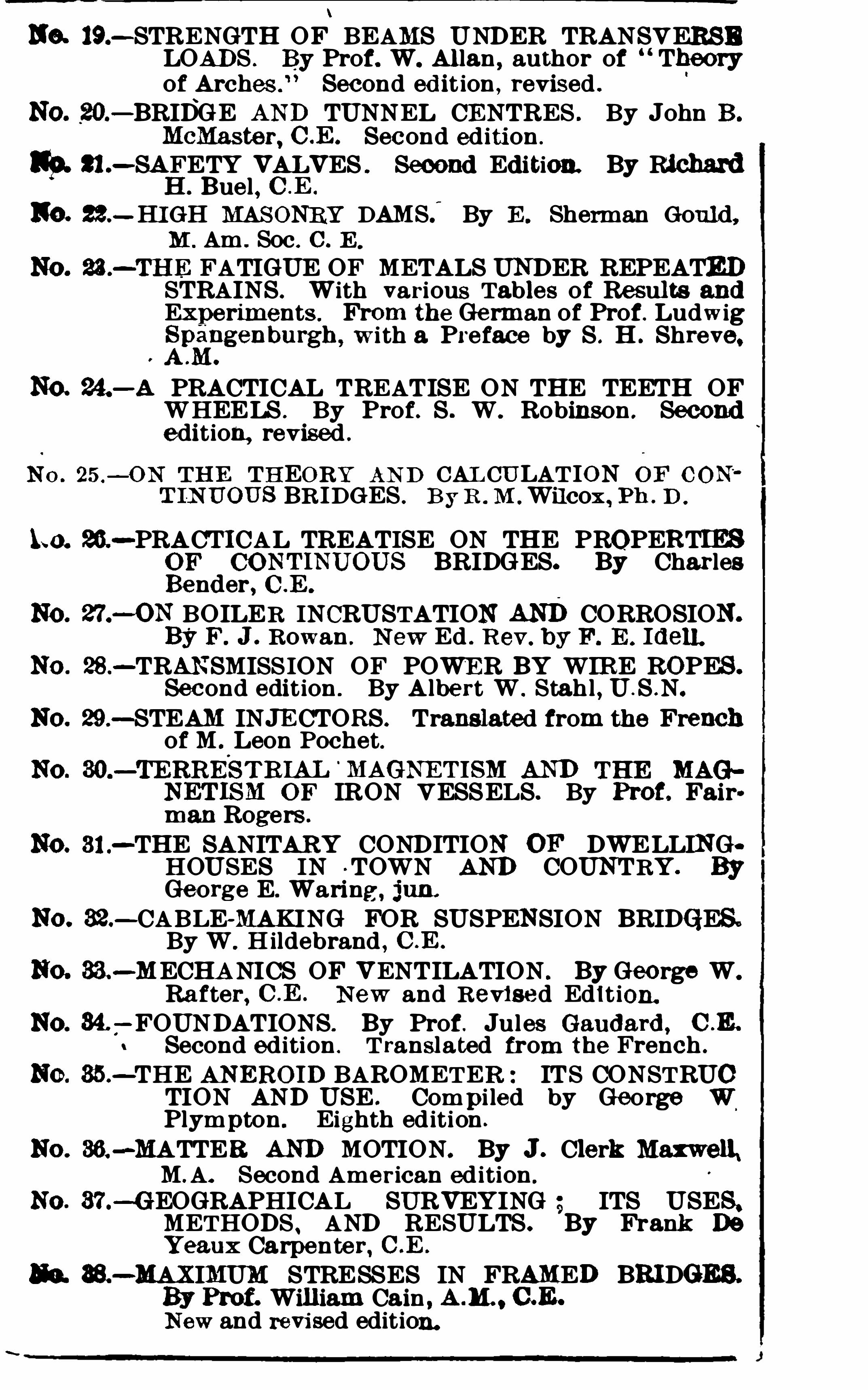
The general form of the cistern barome
ter needs no description ; Fig. 1 shows
the cistern and details at the lower end
Of the instrument .
“The cistern is made
up of a glass cylinder F,which allows the
surface of the mercury to be seen,and a
top plate G,through the neck of which
the barometer tube t passes , and to
which it is fastened by a piece of kid
leather,making a strong but flexible j oint .

1 1
To this plate, also , is attached a small
ivory point h,the extremity of which
marks the comm encement or zero of the
scale above . The lower part, containing
the mercury,in whi ch the end of the ba
rometer tube t is plunged, is formed of
two parts i j, held together by four
screws and two divided rings l m . To
the lower piece j is fastened the flexible
bag N,made of kid leather
,furnished in
the middle with a socket k, which rests
on the end of the adj usting screw 0 .
These parts,with the glass cylinder F,
are clamped to the flange B by means of
four large s crews P and the ring R ; on
the ring R screws the cap S, which covers
the lower parts of the cistern,and sup
ports at the end of the adjusting screw
0 . G,i, j, and k are of boxwood ; the
o ther parts of brass or German silver.The screw 0 serves to adjust the mercury
to the ivory point,and also
,by raising the
bag,so as to completely fill the cistern and
tube with mercury,to put the instrument
in condition for
Sm iths onian Mis . COL, Vol . I .
12
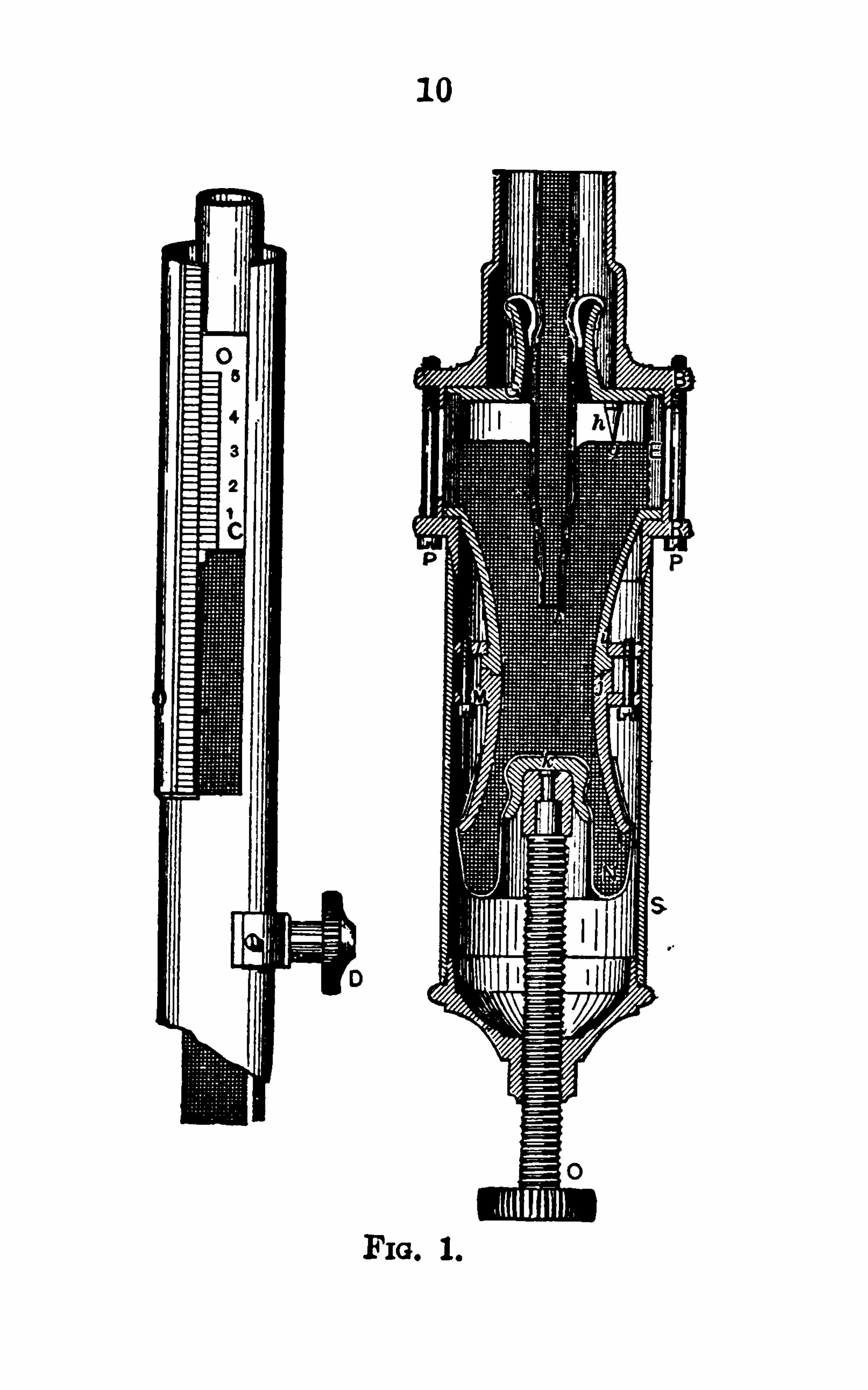
§ 6. Filling the Barometer .— It is no
slight matter to properly fill a barometer.It can best be done by the manufacturer
,
who has all the facilities ; but as it issometimes necessary for the observer to
refill it,the following hints are given .
Tubes require refilling owing to the
breaking of the glass or to the entrance of
a bubble of air.
The mercury should be chemically pure
and free from oxide ; otherwis e it will
adhere to the glass and tarnish . Moreover
,if it is not pure
,the height of the
barometric colunm will not be correct ;only mercury should be used which hasbeen purified by distillation . For the
best results, the mercury should be
boiled in the tube to expel moisture and
air ; but this can not always be done,and
fair results can be Obtained without boil
ing . The following des cription of the
method of filling is from Smithsonian
Report, 1859, page 440, and is recom
mended byWilliamson (p .
“The glass tube,which should be
clean and dry,must have its Open end

14
the several sides,when it will absorb
those minute portions of air,now greatly
e xpanded from removed atmosphericpressure
,that were not drawn at the first
gathering. The perfect freedom from air
is easily recogni zed by the sharp concus
sions with which the colunm beats agains t
the sealed end,when
,with a large vacuum
bubble,the horizontally held tube is
s lightly moved .
”
“A barometer so prepared will probably read lower by a few thousandths
than if the tube had been boiled,but in
a stationary barometer its error will prob
ably not soon change,and carrying on
horseback will be apt to improve it rather
than otherwise,as it is then carried with
the cistern uppermost, and the bubbles
will be jolted toward the open end .
”If
possible it should be compared with
a standard barometer.
§ 7. To fill a tube by bo iling, an
alcohol-lamp is needed,although it can
be done over a charcoal fi re . The lamp
being filled and put in order,begin to fi ll
Williamson on the Barometer, p . 140.

15
the tube by pouring in through the funnelas much warm mercury as will occupyabout fi ve inches ; then, holding the tube
with both hands above the mercury,
heat it gently,and let it boil from the
surface of the mercury downward to the
end of the tube,and then back again
,
chasing all of the bubbles of air upward .
A little practice will make this easy, the
tube being held a little inclined from the
horizontal,and constantly and rapidly
revolved,always in the same direction
,so
that every portion of the metal may be
heated gradually and xuniformly. Afterthis has been done
,let the tube coOl suf
fi ciently to admit of its being held by the
gloved hand,and then pour in enough
warm mercury to occupy several inches
more of the tube,which may
'
now be
held with both hands,one above and the
other below the heated portion. After
boil ing this thoroughly free from air,re
peat the same operation with more mer
c ury added,until the tube is filled to the
end . With care‘
and practice the mer
cury may be boiled entirely free from air

1 6
up to within an inch or less of the end of
the tube . A tube filled in this way mayhave
,in every respect
,as perfect a
vacuum as one prepared by a professional
instrument-maker .
”
8 . In extended barometri c Operations
in the field,a supply of extra tubes is
carried,to be used in case a tube is
broken . These tubes should be drawno ut-so as to be a little longer than they
are required to be when fitted into the
barometer . The open end should be cutoff to such a length that it shall always
be immersed and yet not interfere with
the rise of the lower part Of the cistern .When the instrument is finally put
together,the cork in the upper end of
the brass case should be adjusted soas to hold the closed end of the tubefi rmly.
*
§ 9. Cleaning the Barometer .
— It fre
quently happens that the mercury in thec istern becomes so dirty that the ivory
point,or its reflection in the mercury
,
can no longer be Seen ; this often occurs
W illiam son , p . 138 .

17
even though the barometer be in good condition in every other respect. The in
strument can be taken apart and cleaned
with safety and without changing in theslightest degree the zero of the ins tru
ment .
* Everything us ed in the Opera
tion must be clean and dry . Avoid blowing upon any of the parts
,as the moisture
from the breath is injurious .
“Screw up the adjusting screw at the
bottom until the mercury entirely fillsthe tube
,carefully invert
,place the in
strument firmly in an upright position,uns crew and take Off the brass cas ingwhich encloses the wooden and leather
parts of the cistern . Remove the screwsand lift off the upper wooden piece to
which the bag is attached ; the mercurywill then be exposed . By then inclining
the instrument a little,a portion of the
mercury in the cistern may be poured'
out into a clean vessel at hand to receiveit
,when the end of the tube will be ex
posed . This is to ~ be closed by the
gloved hand,when the ins trument can be
Wflliampon , p . 136.

1 8
inverted,the cistern emptied
,and the
tube brought again to the upright posi
tion . Great care must be taken not to
permit any mercury to pass out of the
tube . The long screws which fas ten the
glass portion of the cistern to the other
parts can then be taken off,the various
parts wiped with a clean cloth or hand
kerchief and restored to their former
position .
”
“If the old mercury is merely dusty
,or
dimmed by the oxide,the cleaning may
be effected by straining it through
chamois leather,or through a funnel
with a capillary hole at the end,of a size to
admit of the passage of but a small thread
Of the metal . Such a funnel is convenientlymade of letter-paper. The dus t
will adhere to the skin or paper and the
filtered mercury will present a clean and
bright appearance . If chemically imu
pure,it should be rej ected
,and fresh,
c lean mercury used . With such clean
mercury the cistern should‘
be filled as
nearly full as possible,the wooden por
ti ons put'
together and securely fastened
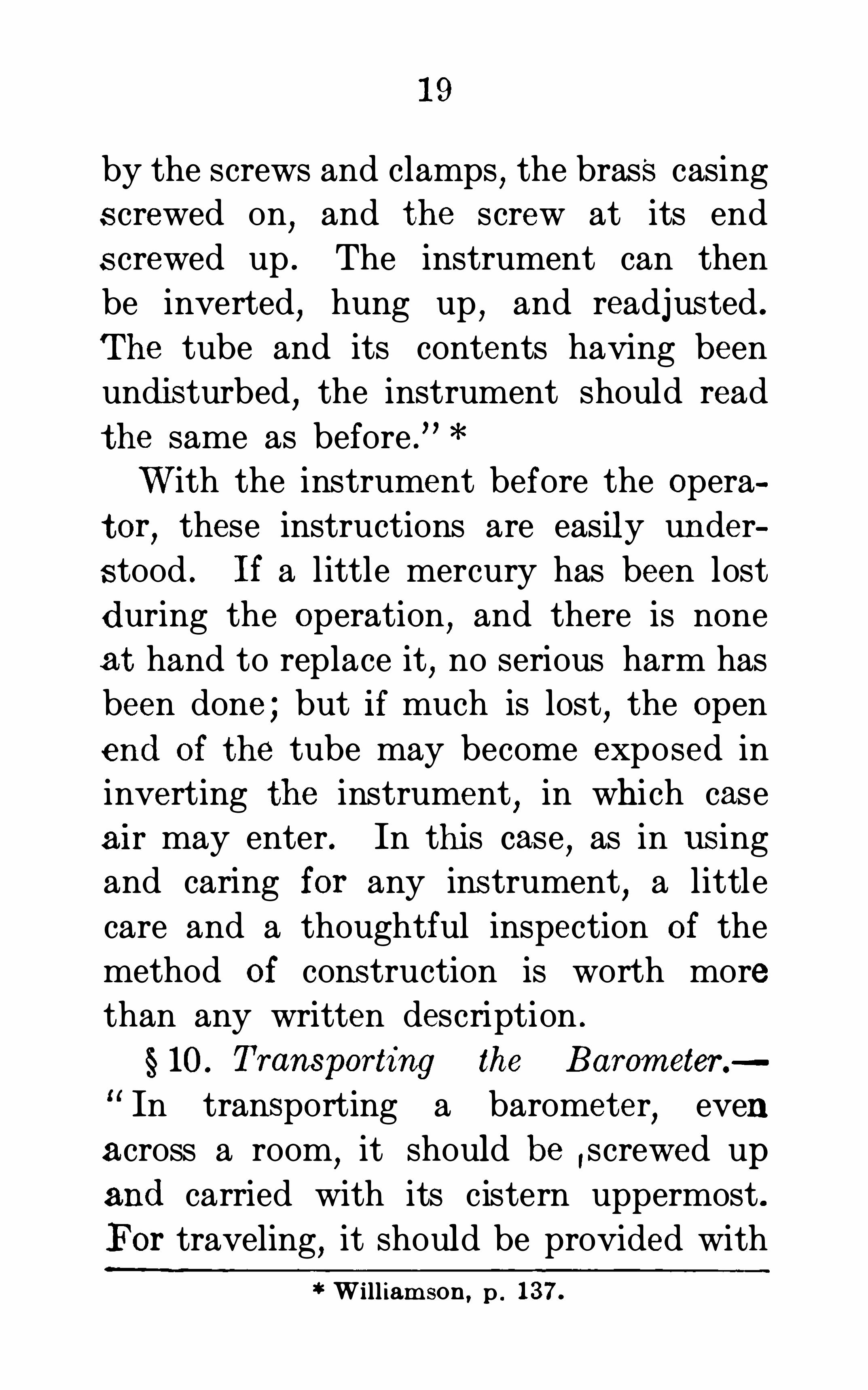
19
by the screws and clamps,the brass casing
s crewed on,and the screw at its end
s crewed up . The instrument can then
be inverted,hung up
,and readjus ted .
The tube and its contents having been
undis turbed,the instrument should read
the same as before .
”
With the instrument before the Opera
tor,these instructions are easily under
s tood . If a little mercury has been lost
during the Operation,and there is none
at hand to replace it, no serious harm has
been done ; but if much is lost, the Open
end of the tube may become exposed in
inverting the instrument,in whi ch case
air may enter. In this case,as in us ing
and caring for any ins trument,a little
care and a thoughtful inspection of the
method of cons truction is worth more
than any written description .
§ 10. Transporting the Barometer.
In transporting a barometer,even
across a room,it should be ,screwed up
and carried with its cistern uppermost .
For traveling,it should be provided with
William son, p . 137.

20
a wooden and leather case. In steam
boats or railroads it should be hung upby a hook in the stateroom or car. In
wheeled vehicles it should be carried byhand
,supported by a strap over the
shoulder, or held upright between the
legs ; but it should not be allowed to
rest on the floor of the,
carriage,for a
sudden jolt might break the tube. If
carried on horseback it should be strapped
over the shoulder of the rider,where it
is not likely to be injured,unless the
animal is subject to a sudden change of
gait . When about to be used it shouldbe taken from its case
,while screwed up
,
gently inverted and hung up,when it can
be unscrewed . While it has its cisternuppermost the tube is full
,is one solid
mass of metal and glass,and not easily
injured ; but when hung up, a sudden
j olt might send a bubble of air into the
vacuum at the upper end of the tube,and the instrument would be useless un
til repaired .
”
Williamson, p . 1 34 .

22
ing the final adjustment,tap the barome
ter a little just above the cistern, to destroy the adhesion of the metal to the
glass . Complete the contact of the mercury and the ivory point
,at the same time
being certain that the barometer hangsfreely
,i .e.
,vertically .
Next tap the barometer gently in the
neighborhood of the top of the mercury
column to destroy the adhesion of the
mercury ; this is very important, since
raising or lowering the mercury in the
previous Operation materially affects the
form of the upper surface . Then take
hOld lightly of the brass casing of the
barometer,not near the attached ther
m om eter,so as not to unnecessarily heat
either the cas e or the thermometer,and
by means of the mill-head screw near the
middle of the tube,bring the front and
back edge of the vernier into the same
horizontal plane with the top of the mer
cury in the tube,jus t touching it and
no more,and then remove the hand.
Move the eye about, and if, in any position
,a line of light can be seen between

23
the mercury and the vernier, the latter
must be moved down a little ; if there is no
line of light,but a large Space is ob
s oured,the vernier must be moved up a
little . As the top of the colunm is moreo r less convex
,when the adj ustment is
c orrectly made a small place is obscuredin the center
,when the light is seen on
e ither side .
Finally having adjusted the instrument
as above,it may be read at leisure . On
the best barometers the scale is usuallydivided to inches
,tenths
,and half-tenths
the vernier reads to one twenty-fi fth
of half-tenths ( 131—5X00 5) or two-thou
sandths
ART . 2 . THE THEORY.
A. COMMON OR STATICAL FORMULA.
§ 12. Fundamental Relations — Suppose
A and B,Fig. 2
,to represent two stations
,
and that it is required to determine the
vertical distance between them . A and Bare not necessarily in the same verticalline . Let C represent any point in A B
,
and D'
a point a small distance below 0.

24
Suppos e the pressure per square inch atDto be represented by P
,and the difference
in pressure between C and D by dP.
Let a=the of a cubic inch of air
-A
B
FIG . 2.
under the conditions of pressure,tempera
ture,etc .
,existing between -C and D; X =
the elevation Of A above B,in feet .
It is clear that the increase in pressurefrom C to D is equal to weight Of a colUmn of air between C and Dwhose crosssection is 1 sq . in . ; or,
adx= dP ( 1 )
§ 13. If a0= the weight of a cubic inch
of dry air at the sea-level in latitude 45°“
at the freezing poin t when the barome

25
ter stands at inches,and P
o= the
pressure under which aois determined
,
then by Boyle and Marriott’s ‘
law
azaozs P
Pa= a
0P0
(2)
IfHandH0 represent the heights of
the barometer assuming the temperatures
to be the same, corresponding to the
pressures P and P0 and m = the weight ofa cubic inch of mercury
,then
P Hm Hm3
P, Hem 29.92mU
P aOHm
029.92m
(4)
The weight of a cubic inch of air forany other temperature t is
aoHm 1
m + ct)
in which a is the coefficient Of expansion
Of air . For any latitude 95, (5) becomes
aOHm 1 1
29.92m ( 1 + cl) ( 1 cos . 2q5)very nearly. (6)

26
14 . Substituting the value of a from
(6) in and d for dP,we have
dz: 299 231 04 cl) (1+ cos .2g15)‘
d
%1-I
O
which integrated between the limitsH’andH
,,the heights of the barometer at
A and B respectively, gives
(1+ 00260 cos .
0
N log3 (7)
Assuming the mean Of the temperature
of the air at A and B to be the mean tem
perature Of the air between A and B,we
may put
tT 1
2
41
1
,T’ and T
1
being the temperatures of the air atAandB . Making this substitution and pas sing to common logarithms
,
X ft.= 5.74 log .g— j 1+ c
T
3T.
(1+ cos . 296) (8)This formula includes the principal
lations involved in determining difference

27'
of height with the barometer. The final;formula to be used in practice has been;
given differently by different investiga
to rs,according to the values chosen for
the constants,to the individual prefer
ence for one form over another,and to
the degree of refinement desired . A few
Of these special formulas will now be con
sidered briefly .
15. The Constanta— The value of
2—1, generally known as
the barometric coefficient,will
'
dependupon whose values of the dens ities of air
and mercury are used . Boit and Arago
found *gi = l0467, which makes the ba0
rometer coefficient ft.
meters) . Regnault’s values * which are
the most recent and probably the most
accurate,give feet Ine
ters) . Raymond (1803) found* the value
of the barometric coefficient by determin~
ing the value it should have to make theresults by the formula agree with those"
Sm ith,Miscel. Col Vol . I. , Pt . IV . , p . 9 .
the term

28
furnished by trigonometrical leveling. The
value obtained in this way is ft.
meters) ; but even under the mostfavorable circumstances
,the Observa
t ions,eight in all
,
* were too few to determine such a coefficient with sufficient accuracy . For reasons which will appear in
this and Chapter IV.,it is highly probable
that Raymond’s coefficient is the least
accurate,although it has been m ore . fre
quently used than either of the others .
The term 1+ is known as
the temperature term . 0 is the coeffi
cient of expansion of air,and is equal to
per 1° C . ; it is usually approxi
mated at If this value be sub
stituted,the temperature term becomes
2 (T+T) 11+
1000
TIand T’ are given in Fahr . degrees , it is
easily seen that the temperature termT,+T
’— 64
900
for centigrade degrees ; if
becomes 1+
U . S . C . G . Report , 188 1 . p . 235 .

30
X= 60158 .6
10H1 (1+ cos . 2q5) (9)
g'H’ X+ 52252
20886860
In which X is in feet and the tempera
tures in Fahrenheit degrees ; X in the
last term is the value Of the precedingpart oft he formula .
Since the entire correction for the
variation of gravity is always quite small,
and since at best the barometer can ber ead only to thousandths of an inch
,
which corresponds to about 10 ft. of alti
tude,the latitude term and also the term
for variation of gravity with the altitude
may be neglected without materially af
fecting the accuracy of the results . Far
ther on it will be shown that the appearance of extreme accuracy by retaining
these terms can be regarded only as a
mathematical illusion,inapplicable to any
real state. cf practice .
17. Babinet’s Formulas — The follow
ing formula by Babinet has no term for
at Sm ithsonian Misc el. COL. Vol . I , Part IV. (Guyot’sCo llection ) , p .

31
the variation of gravity . It is sometimes
c laimed * that the barometric coefficientwas adjus ted to meet this correction ;
‘
but
from the nature of the case this can not betrue
,except for some assumed mean.However
,notice that the coefficient is
larger than any previously given,see § 15.
The formula is,for X in feet
,and Fahren
heit degrees,
(T’+ T — 64)
IfH' andH, do not greatly difi er it canreadily be found that
H, H,—H’N log .H’
Making this substitution in (10) givesBabinet’s approximate formula
H,—H’ — 64)
X ft. 1+900
(11)
The error involved in the above formula is inappreciable for elevations lessthan feet.
”T
Ibid ., p . 9 . 7 Ibid ., p . 68 .

32
The following * is essentially the sameas Babinet’s approximate formula exceptthe form of the temperature term
H—H’ T,+ T
’1 10H
,+H'Jr 900
x4200
4 10 ft. ( 12)
X 54500
The last two terms show the degree Of
relian ce to be placed upon the result .
18 . Correction for Temperature ofBarometer —In all that has preceded
,it
has been assum ed that the two barome
ters were at the same temperature,which
assumption will rarely or never be true .
Therefore the heights of the barometer,
before being ins erted in the precedingformulas
,must be reduced to the corre
sponding heights which they would have
at a common temperature,or a term
must be included in the formulas them
selves to correct for the difference in tem
perature of the barometers . Both methods are employed .
The expansion of mercury for 1° F. is
U . S . C . G . Report, 1876, pp . 352-3 ; see alsoLee’s Table, p . 151 (3d

33
and that of brass,of which
the scales are generally made,is
104 ; the difference, the relative expan
sion ofmercury,is For the cen
tigrade scale this difference isHence if h' represents the height of thebarometer at the upper station
,reduced
to the temperature of the lower,and t’
,t,
the temperature of the barometers atthe upper and lower stations respectively
,
we haveh’ H’[1 — d(l’ (13)
in which d stands for one of the abovedifferences
,according to the kind of
thermometer used .
19. Ins tead Of reducing one barom
eter to the temperature of the other,
both may be reduced to any other tem
perature assumed as a standard; the
freezing point ofwater is generally chosen .
Equation (13) is still applicable, pro
vided t, be cons idered as representingthe temperature of melting ice (32
° F. or
and t’ the reading of the attachedthermometer The formula for redue
tion must now be applied to both read

34
i—ngs of the barometer . Numerous tables :
have been computed for facilitating thisreduction — see Guyot’s Collection
,3d
Edition,Group C
,pp . 61— 127 ; Group D,
pp, 30, 46, 53, etc . Lee’s Tables,3d Ed .
,
pp . 152—9 ;Williamson on the Use of theBarometer
,pp . 1—64 of the Appendix
,etc .
20. The correction for the difference
in temperature of the barometers may be
made by ins erting a term 1n the general’
formula Thus,in it is only neces
sary to multiplyH’ by [1 — d(t’ to
reduceH’ to the corresponding height atthe temperature of the lower barometer .
Making this correction, using Babinet’sbarometric coefficient 17) and approx
imating d (0 000896) at .0001,we get
Bailey’s Formula.
*
X ft . 60346 loggi 1+T'
+ Tl 64
900
1+ cos . 295
(14)
§ 21 . Correction forHumidity.
—In de
ducing the preceding formula,it was
as sum ed that the atmosphere was cOm
Guyot’s Collection ,D, p . 69 .
1 — t,)
35
posed exclusively of dry air ; really it isa mixtur e of air (oxygen and nitrogen) ,c arbonic acid
,and watery vapor . The
carbonic acid is very small and nearlyconstant
,and hence it need not be con
s idered here ; but the watery vapor is
both large and variable . If dry air and
aqueous vapor had even nearly the samedens ity under the same conditions
,the
presence of the latter would not affect the
problem ; but watery vapor is only fi ve
e ighths as dens e as dry air,and the
weight,a,of a unit Of volume Of the at
m osphere will depend upon the relativeamount of vapor which it contains . Ac
curate hypsometry accordingly demands
that some account shall be taken of the
aqueous contents of the atmosphere,and
a humidity term has been included in
many barometric formulas .
The introduction of a humidity term
in the barometric formula requires that
the hygrometric state of the air columnshall be known . Accordingly an Observa
tion with the hygrometer is made at eachs tation . For this purpose the wet bulb

36
hygrometer or psychrometer is generallypreferred
,because of its greater accuracy
and convenience ; knowing the readings
of the wet and dry bulb thermometers,
the barometric pressure due to the aqueous vapor in the air may be determinedfrom tables
,
* which are the results of
experiments . The observed heights of
the barometer may be corrected for thepressure of the aqueous vapor before sub
stituting them in the formula ; or the
Observed heights may be used uncor
rected,and the resulting altitude be mul
tiplied by afactor -to correc t for the hu
midity‘
. The latter method seems to be
generally preferred .
In a very general sens e,in temperate
climates near the sea—level the amount
of vapor in the atmosphere is from
to of an inch,or about one-hundredth
of the whole
§ 22 . Bessel was the first to proposethe introduction of a correction for theeffect of moisture . Plantamour
’s for
Williamson on the Barom eter,Table C, of theAppen
Guyot’s COL, Group B , pp . 46-72 ,pp . 102—6 .

38
in the stratum of air next to the surface
of the earth,which probably contains the
greatest amount of moisture,and which
is therefore least representative of the
vertical column between the two stations .
At any rate,the gain
,if there is any
,is
not sufficient to compensate for the extra
trouble in making the observations and
the undesirable complication of the for
mula ,
The question of the desirability of ap
plying a correction for the hygrometric
state Of the atmosphere is so intimately
connected with the phase discus sed indivision B of this article
,which imme
diately follows, that nothing farther need
be said here .
24 . Conclusion — The preceding donot comprise all the formulas which have
been proposed for barometric levelin g,
but include the more common ones,and
illustrate all the principles involved,ex
cept those discussed in division B . Someof the omitted formulas are approxim ate,some have empirically determined pres
sure coefficients,etc . Owing to the limi

39
tations discussed in the next division,it
matters comparatively little which of the
generally recognized barometric formulas
is used .
B . DYNAMICAL FORMULAS .
25. Defects of StaticalFormulas - Allthe formulas referred to above are depend
ent upon the assumption that the air is in
a state of statical equilibrium . If a con
dition of statical equilibrium were possi
ble,we might suppose that the whole
atmosphere was arranged in a system of
horizontal layers,each of. which would be
denser than the one above it and rarer
than the one below,each being uniform
throughout in temperature and humidity .
The temperature and hum idity might
vary from stratum to stratum uniformly,
or according to some more complicated
law .
The fundamental assumption in deducing the preceding class of formulas is : 1 ,that a difference of pressure is due only
to a difference of elevation ; 2, that the
temperature of the air varies uniformly

40
from one station to the other ; and 3, that
the temperature of the air between the
two stations is the same as that of the
vertical column between the horizontal
planes of the two points . The introduction of a correction for humidity involves
essentially the same assumptions as the
temperature term .
26. The air is never in a state of stat
ical equilibrium,but is perpetually uh
dergoing local changes of pressure,tem
perature, and humidity . For example,
the sun,which is the ultimate source of
all disturbances,shines only by day .While it shines a certain amount of heat
is imparted to the whole atmosphere,but
a much higher temperature is given to
the ground,and is communicated to the
contiguous layer of air . At night the atm osphere loses heat by radiation to space,but the ground loses it still more rapidly
and imparts its low temperature to the
lowest stratum of air . The lower strata,
therefore,have exceptional warmth by
day and exceptional coolness by night .
If the air is moist it intercepts a greater
41
quantity Of solar heat than if it is dry,so
that a less quantity reaches the ground,
while at night atmospheric moisture
checks radiation from the ground . The
power Of the earth’s surface to receive
or sto re or part with heat varies with its
character . Naked rocks and cultivated
fields,bare earth and gras s
,forest and
snow are affected very differently by the
heat rays of the sun ,and exert equally
diverse influences on the adj acent air,so
that one tract Of land is often in a con
dition to heat the air while an adj acent
tract is cooling it . Then,too
,the sun’s
heat is un equally distributed through theyear ; outside the tropics there is a pro
gressive accumulation of heat throughsummer and a progressive loss throughwinter . The ocean undergoes less change
of temperature than the land,and its rate
Of change is slower,so that there is fre
quent,and indeed almost continuous
,
contrast Of condition between it and thecontiguous land . As a result Of all these
influences,together with others that
might be enumerated,the equilibrium of

the air is constantly overthrown,and the
winds,which tend to readjust it
,are set
in motion .
The temperature of the air is continu
ally modified by external influences ; the
static order Of densities is broken and
currents are set in motion ; and the cir
culation and the inequalities of tempera
ture conspire to produce inequalities of
moisture . Every element of equilibrium
is thus set aside,and the air is rendered
heterogeneous in density,temperature
,
and composition .
”
27. A consideration Of these facts
will show the inaccuracy and insufficiency
of hypsometric formulas founded upon an
assumed state of static equilibrium . SomeOf the defects of statical formulas will be
considered in detail before discussing for
mulas which seek to overcome thes e diffi
culties .
28 . Gradient — Let A,B
,and C des
ignate three barometer stations . LetA’
,B’
,C’ designate points vertically above
each at which the pressure is the same or
G . K . G i lbert , in U . S. Geological Report for 1880—1 .

43
common . The plane passing through .
A’B’C’ is then a surface of equal pres
sure . If the air were in a state of equilibrium
,it would be a level plane
,but in
fact it will be inclined in some direction .
This inclination is called the barometric
gradient.
Instead of considering only three poin ts,
we can in imagination project through
the air a surface containing all points
which have the same pres sure . If the
atmosphere were at rest,this surface
would be a horizontal plane, but under
the actual conditions it is never a plane
and is ever undulating .
”For small areas
under ordinary conditions,this surface
would probably not differ much from a
plane .
Conceive another surface passed through
all points'
at which the pressure differs
from the preceding one by any constant
quantity . With atmospheric equilibrium
all such surfaces would be both level
and parallel,but in the actual case none
are level and no two are precisely parallel .When widely separated surfaces are com

44
pared,the variations from parallelism
are often so great that their inclinationsabove the same locality have Oppositedirections . The atmospheric gradient at
the surface Of the ground may therefore
differ greatly 1n amount and direction
from the simultaneous gradient at a con
siderable altitude above the same spot .
§ 29. The necessity Of considering thebarometer gradient is apparent when it
is remembered that the air is continuallyin a state Of motion
,as is shown in the
variation of the height of the barometer.For example
,if A and B are two stations
,
and the atmosphere at rest,then the sur
face of equal pressure,BC
,is a horizon
tal plane ; and AC is the difference of ele
vation which would be obtained by ap
plying any one of the preceding baro
metric formulas . If the air is not in
static equi librium,the pressure at A will
be greater or less than before,and the
surface of equal pressure may lie above
or below BC ; if the pressure at A is
greater then the average,the surface of
equal pressure is above C,say at E
,and

46
taneous and alike in amoun t,no error
would be produced by the barometer
gradient ; but these conditions are seldom
or never realized .
§ 30. The variations in atmosphericpressure
,and the consequent variations
of gradient,are so complicated that it is
impossible to trace the relation between
cause and effect ; but there are two varia
tions that are pretty well understood .
One has a daily period,and is caused by
the variation in the heating effect of thesun between day and night ; the second
has a yearly period,and is caused by the
variations of the sun’s heat at different
times of the year .
§ 3 1 . Diurnal Gradient. -It is a fact
fam i liar to meteorologists that the pres
sure Of the air everywhere undergoes a
daily oscillation . The gradient intro
duced by this daily change is called
diurnal gradient . The pressure has two
maxima and two min ima which are easily
distinguishable . Near the sea-level the
barometer attains its maximum about 9
or 10 A. M. In the afternoon there is a

47
minimum about 3 to 5 P. M. It thenrises until 10 to midnight, when it falls
again un til about 4 A. M.,and again rises
to attain its forenoon maximum ; the day
fluctuations are the larger.The daily oscillation is subj ect to varia
tions in character and magnitude . The
oscillation is greatest at the equator and
diminishes toward the poles,but is not the
same for all places of the sam e latitude .Within the United States it varies between40 and 120 thousandths of an inch .
Changes of altitude Often cause a markedvariation in the amoun t and character ofthe diurnal oscillation . The differencewhich pertains to latitude does not mate
rially affect the ordinary hypsometricproblem
,but the difference depending on
the altitude has a very important effect .32 . Annual Gradient— The annual
progress of the sun fromtropic to tropicthrows a preponderance of heat first on
one side Of the equator and then on the
other,which produces an annual cycle of
changes in the pressure and gives rise towhat has been called the annual gradi
48
ents . The amount of this variation is
quite small near the equator,but in
creases rapidly toward the poles ; atthe equator it rarely exceeds i Of an inch
per year , while in the polar regions it isOften as much as 2 or 3 inches in afewdays .
”
33 . Nou-periodic Gradients - In ad
dition to the diurnal and annual varia
tions in the pressure there are others due
to the same general cause,the heat of
the sun,but so modified by the local con
ditions— topography,the humidity
,winds
,
storms,etc .
— as to make it impossible to
discover the law of their action . Thesenon-periodic variations are much greaterin amount and more rapid in their actions
than either of the others .
§ 34 . Temperature Gradient. It has
just been explained that the variations
of pressure are due primarily to inequali
ties of temperature ; it will now be shownthat
,if differences of elevations are deter
mined by the '
formulas commonly used,
’ *Williamson , p . 68 .

49
the temperature is directly responsiblefor other and generally more serious
They arise from the difli culty
of determining the temperature of the
vertical column of air between the two
stations .

50
Let A and B (Fig. 4) be two stations
the difference Of elevation of which is to
be obtained from Observations of the
barometer and thermom eter made at
each . Let it be assumed that the pressure
Observed at B is the same as that at Cvertically over A and on . a -level with B.
To use the statical or comm on formulas,
the temperature of the column AC mustbe known ; in applying these formulas
it is assumed that the mean tempera
ture of this column is equal to the
mean of the temperatures Observed at
A and B .
How admis sible this assumption is
will appear at once when the mann er inwhich the air acquires and loses heat isrecalled . The body of the atmosphere
is heated directly by the sun and gives
off its heat by radiation into space . The
surface Of the earth is heated and cooledin the same mann er
,but many times
more rapidly,so that by day it is always
much warmer than the body Of the air,
and by night it is much cooler. A layer
of air next to the earth receives its warmth

51
from the earth,and is thereby caused to
differ widely in temperature from the
remainder of the atmosphere . Not only
is the greater part of the column inac
cessible to us,but that portion to which
our observations are restricted is the por
tion least representative of all.”
By measuring the difference Of eleva
tion of two points with the Spirit level
reversing the barometer formula,and
computing the temperature of the air
column,it has been found that in middle
latitudes the average daily range of the
temperature of the body Of the air is .
about and that of the superficial
layer,is from 10
° to 20° near the sea
shore,and from 20
° to 35° in the in
terior of continents . There is a stratum
of air near the surface (Fig. 3) whichoscillates daily through this wide range
,
while the temperature of the upper andlower portion of the column AC is re
latively constant . Therefore the mean
of the Observed temperatures absolutely
G ilbert in U . S . G . S . Report .
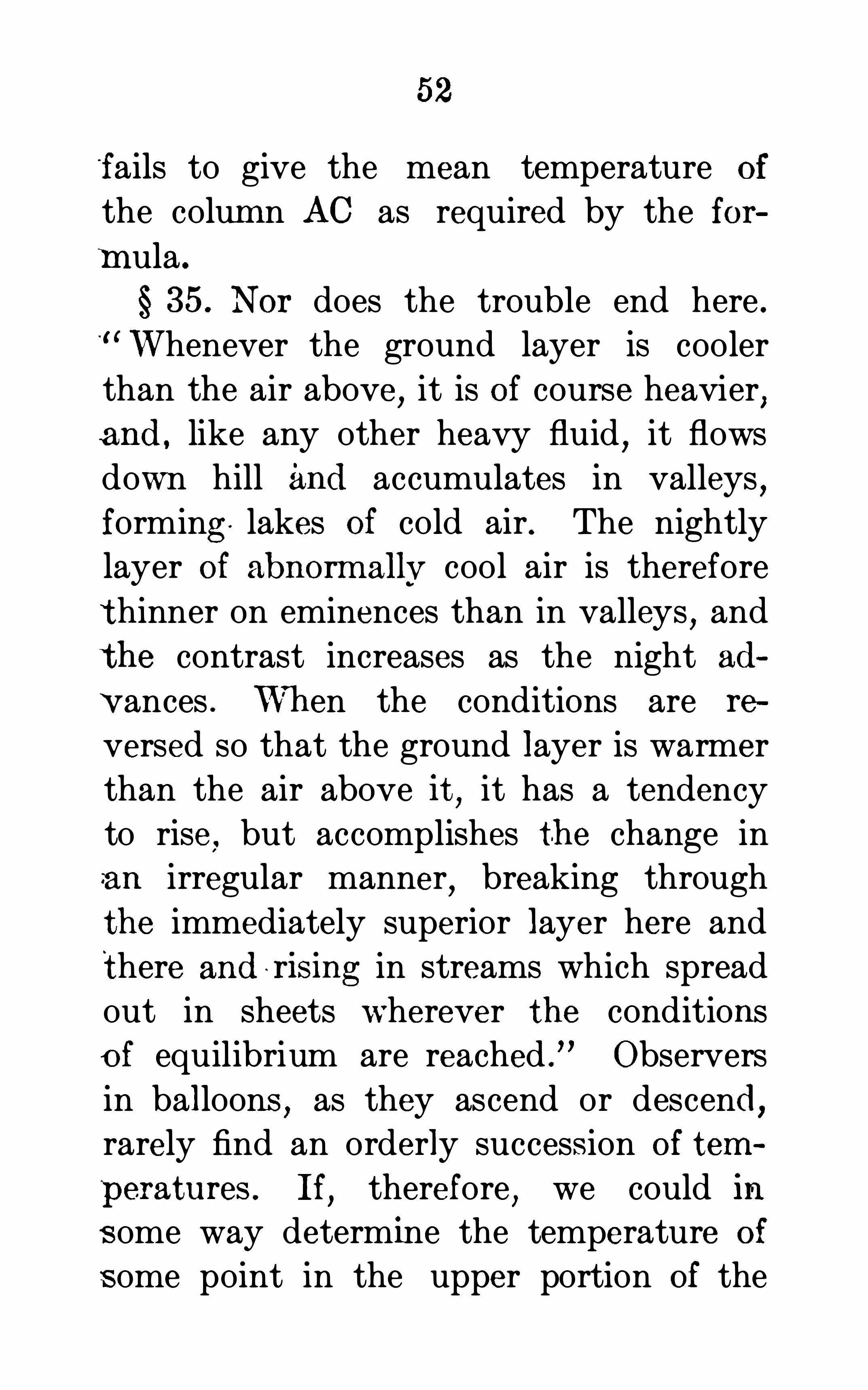
52
fails to give the mean temperature of
the colum n AC as required by the for
mula .
§ 35. Nor does the trouble end here .Whenever the ground layer is cooler
than the air above,it is of course heavier
,
and, like any other heavy fluid,it flows
down hill and accumulates in valleys,
forming lakes of cold air . The nightly
layer of abnormallv cool air is therefore
thinner on eminences than in valleys,and
the contrast increases as the night ad
V ances . Wh en the conditions are re
versed so that the ground layer is warmer
than the air above it,it has a tendency
to rise,but accomplishes the change in
an irregular manner,breaking through
the immediately superior layer here and
there and r ising in streams which spread
out in sheets wherever the conditions
o f equilibrium are reached .
”Observers
in balloons,as they ascend or descend
,
rarely find an orderly success ion of tem
peratures . If,therefore
,we could in
s ome way determine the temperature of
s ome point in the upper portion of the

54
state are still further increased by the
laws of condensation . At the surface of
the earth there is an almost continuouspassage of moisture from ground to air
,
only a part Of the total exhalation being
returned as dew. The daily circulation
incited by the heat of the sun carries the
moistened air upward and eventually the
water is returned to the earth in the form
of rain or snow,but the condensation
and succeeding precipitation are'
exceed
ingly irregular . W'henever,therefore
,a
current of air moves upward and its
temperature is lowered by rarefaction,a
point may be reached where the aecompanying vapor can no longer exist as
such,and is condensed to cloud or even
to rain or snow . On the other hand,
whenever a current Of air moves clown
ward,its capacity for moisture is in
creased,and it acquires a quasi-absorbent
power,so as to take up water from what
ever moist surface it touches .
”
The irregularities of humidity are
greater proportionallv than the associ
ated irregularities of temperature, but the

55
error in the. difference of altitude due tohumidity is less than that due to tem
perature, because humidity is a muchsmaller factor of hypsom etrlc problems .
§ 37. Ferrel’s For mula.
—Ferrel * has
deduced from a consideration of dvnam
ical principles,a barometric formula
which distinctly recognizes the “ defects,
as discussed above, Of formulas foundedupon a statical condition of the atmos
phere, and which indicates a method Of
remedying them . Although the formulais very‘ carefully and ingenious ly worked
out, yet it is pr obably of little use for
o rdinary hypsometrical work,since it
requires observations to be made for a
long time over a cons iderable area,to get
the data by which to compute corrections
for gradient, temperature, and humidity .Without the data for making these
reductions , this for mula is essentially the
same and has essentially the same defects
as the formulas depending upon a staticalcondition of the atm ospherefr
U . S . C . S . Re port , 188 1 , pp . 225—68 .
1‘Wm . Ferre .
l in U . S . C . G . S . Report, 188 1 , p . 243 .

56
38 . Gilbert’s Formata.
— Gilbert* has
developed a method for deter mining
heights with the barometer which does
not require Observations of the tempera.
ture and hum iditvof the air. His methodrequires simultaneous Obser vations of the
barometer at three stations,the verti
cal distance between two oi which is
known ; from the known difference between two of the stations and the Obser
vations at each, the actual density of the
air can be found ; then the true density
can be used to compute the difference of
elevation between either of thes e stations
and the third .
The method is most accurate when thethree stations are in the same vertical
and when the one whose elevation is
desired lies between the two,the differ
ence of whose elevations is known ; themethod is applicable
,but is less accurate
,
when the stations are not in the samevertical
,or when the one whose height is
sought lies either above or below the
other two .
~
In U . S . Geol . S . Report , 1880-1 .

57
One of the distinctive characteristics
of this method is that it Observes density
directly,whereas other methods Observe
temperature and moisture only and de
duce density . The only reason which has
ever existed for measuring the tempera
ture Of the air and the moisture in it has
been to ascertain its densitv. A second
distinctive feature is that this method
employs in its determination of dens ity a
column of air comparable in height with
the one to be measured and fairly
representative of it,while other methods
base their diagnosis of the column to be
measured on density determinations made
close to the ground,where
,as a rule
,the
conditions are not representative .
” It
will be show n presently that this method
also has serious defects .
§ 39. The formula for this method isdeduced as follows :
Let L,N,and U represent the altitudes
of the lower new,and upper stations re
spectively; let I, n,and u represent the
synchronous barometric readings at these

58
same stations corrected for temperatureof the instrument and instrum ental er
rors . Let E = the vertical base line,or
the known difference of altitude of the
upper and lower stations,E =U— L.
Let A= the required difference of alti
tude N — L,and let a=an approximate
value of A .
S ince E=U— L,
and A=N—L,B—A=U—N.
For convenience refer all vertical distances to the lower station as an origin .
If for the present we neglect the decrease in temperature and moisture with
an increase of the altidute, and assumethat the accidental or temporary varia
tions Of density due to temperature and
humidity are the same in both columns,
the following proportion may be made
The approximate the true heightheight of the Of the base
"
base line line,B
,
the approximate the true h’ghtheight of the of the newnew station station
,A.

59
The approxim ate height (length) Of the
base line,as deduced from the readings
of the barometer at the two stations is ,C (log . l— log . u) in whi ch 0 is the barometer constant . In the same way the
approximate height of the new station
above the lower is C (log . l— log . n) .
Substituting these values, the above proportion becomes
,
C (log . l— log . u) B
C (log . l— log . n) :A.
or a=Blog . l— log .
in which a islog . l— log . u
written instead Of A,owing to the neglect
of the variation of temperature andhumidity with the altitude .
40. The preceding equation would
give the correct result if the atmospheric
column were uniform in temperature,
and if its aqueous vapor were uniformly
distributed ; but since this is never thecase there must be added a term whichshall take account Of the variation Of
temperature and moisture with the altitude .

60
It is well known that in a general waythe temperature and moisture decrease
with the altitude ; but the exact law of
this variation has not yet been discovered .
Therefore,before the correction to be
added to equation (15) can be deter
mined,it will be necessary to assume
some law for this variation .
“If the air were of uniform dens ity,
and the element of temperature were introduced alone
,the high temperatures
at low altitudes would cause a dilation
there,and the low temperatures at high
altitudes would cause a contraction,and
the resulting distribution of densities
would be characterized by an increase
from below upward . If the air were of
uniform density and the element of vapor
distribution were introduced alone,the
greater per cent . of aqueous vapor (which
is a rarer gas than dry air) in the lower
strata,would cause them to be relatively
rare,and the resulting distribution of
densities would be characterized by anincrease from below Con
U . S . Geological Survey Report, 188 1 , p . 44 1 .

62
tween the lower and the new station is at
a point i above the lower. The vertical2
Bd18tance between these po1nts Is —
2—
2
The decrease of dens ity from the middle
point of the colum n A to the middle point
of the column B isE
;A
% ; that is , theB A
mean density of the column A is2D
greater than that of the column B .
In deducing the first te rm (15) of the
proposed formula,it was assumed that
the density as far as it depended upon
temperature and humidity was uniform
throughout both column s ; but we have
jus t shown that the element of the den
sity varies directly as the altitude ; con
sequently a term must be added to (15)to correct for ' the variation . It has j ustbeen shown that the mean dens ity of A isB— A
2Ddens ity of B is the unit or standard d en
sity cons equently,to express the dens ity .
greater than that of B . Themean

63
of A in terms of B,the density of A
,as
assumed in must be diminished byB — A
—
2DA .
Finally,the neglect of the variation of
density with temperature and humidity
assume too great a density for column A,
and since heights are inversely propor
tional to densities,that which makes the
density too great makes the height too
small ; therefore the height of A as de
duced from (15) must be increased by theB — A
quantlty2D
A .
Adding this term to (15) gives for the
height A of the new station,
log . l— log . u 2D (10)
Since the last term is.
always small,a
can be substituted for A,thereby making
the formula more convenient to compute .
42 . If the position of the new station
be referred to the upper station instead
of the lower,the above formula will re
main unchanged,except land n
,and land
uwill change places .

64
The formula is applicable,even though
the new station is'
not intermediate in
height between the other two . If the new
station is above both the others,the
quantity (B — A) then becomes minus, and
the last term is subtracted ; if the new
station is below both the other two,the
num erators of both fractions will be minus,and the result will be the sum of the two
terms .
*
43 . The quantity Dcan be found onlyby experim ent ; to find it
,observe the
barometer at all three stations,determine
A and B by a spirit-level,and compute D.
The experiments should cover a great
range of conditions so as to secure a fair
mean value . Unfortunately D has not
yet been determined from suffi ciently
varied conditions . The only value known
is one determined by Gilbert from Obser
vations at only two sets of stations,and
o ne Of them was not very satisfactory . In '
this way it was found that D= 245,000
feet .
The internal evidence of the observa
G ilbert , p . 442 .

65
tions from which this value is derived is
such that it is probable “its real value
will eventually be found to be somewhatsmaller than the one provisionally as
signed .
”
Happily,the last term is always rela
tively small, and hence any uncertainty
in the value of D will have only a smalleffect upon the final result . The uncer
tainty in the value OfD is the chief defectin this formula . Introducing . this value
ofD, (16) becomes
log . l— log . n A(B — A)A(m feet) — Blog . l— log . u(17)
log . l— log . n
+A(B — A)
log . l— log . u
(18)
44 . Reduction Tables — The use of
all the preceding formulas is very much
simplified by tables which facilitate their
application . Guyot’s Collection (Smith
sonian Miscellaneous Collection,Vol . 1)
contains tables for the application of allthe principal statical formulas The Ap
A (in meters) B
G ilbert , p . 502.

66
pendix ofWilliamson On the Use of theBarometer contains a series of tables forLa Place’s form of Plantamour
’s formula
with Regnault’s coefficient . The
same tables are also given in Lee’s Tables,
pp . 148— 182 . The U . S. Geological Sur
vey Report for 188 1 contains the only
table necessary in applying Gilbert’s for
mula .
Tables are useful where a great num
ber of observations are to be reduced ;but they generally contain an unneces
sary number of figures,and hold forth a
show of extreme accuracy which the na
ture of the observations themselves can
not justify.
45. In the succeeding article it will
be shown that statical formulas are gen
erally applied in such a way as to largely
eliminate the defects referred to in this
section . It is impossible to completely
eliminate the errors due to gradient,tem
perature, etc .
,and
,consequently
,differ
‘
ence of elevation cannot be determined
with precision by means of the barometer .
67
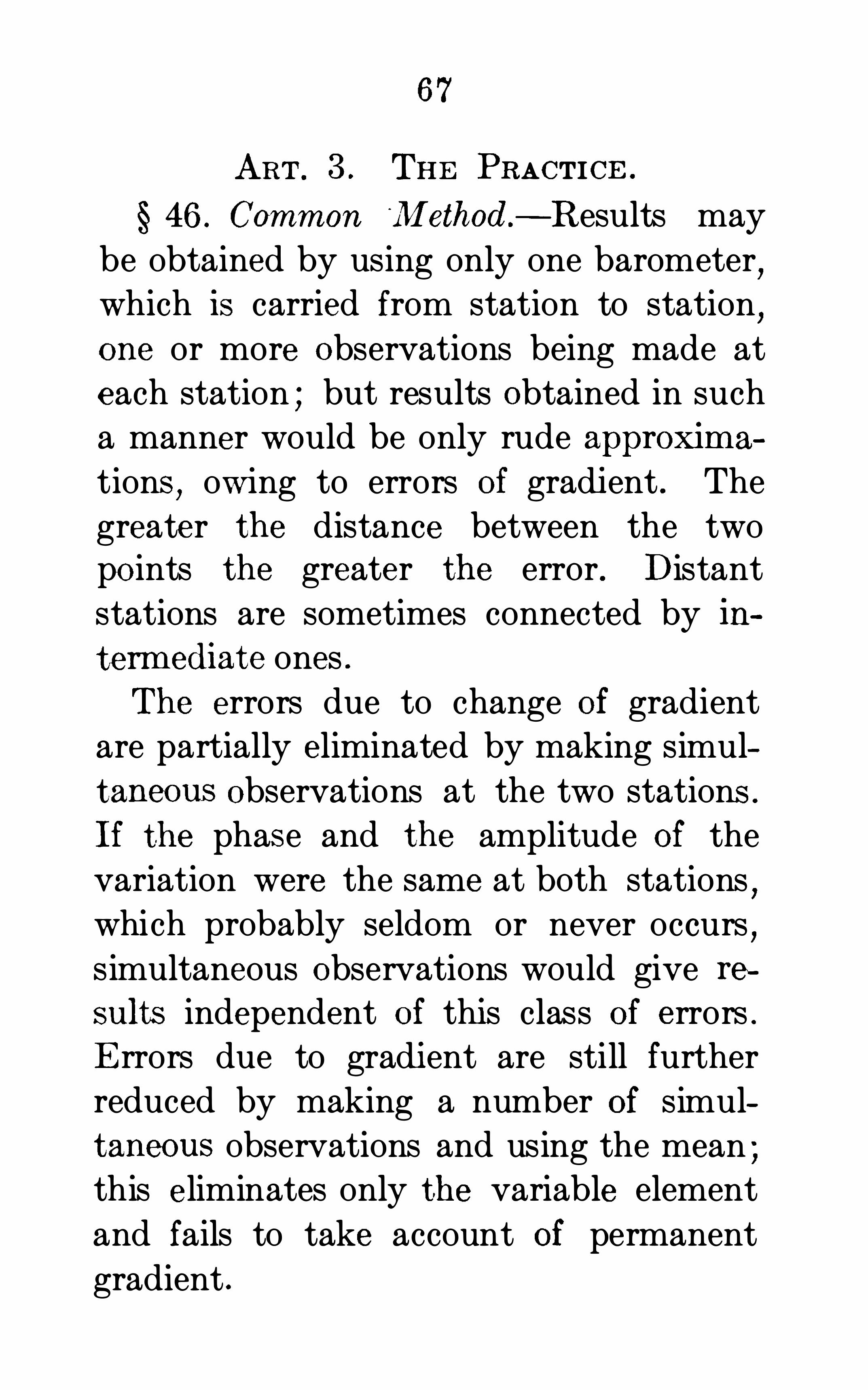
ART . 3 . THE PRACTICE .
§ 46 . Common‘
iMethod.
— Results may
be obtained by using only one barometer,
which is carried from station to station,
one or more Observations being made at
each station ; but results Obtained in such
a manner would be only rude approximations
,owing to errors of gradient . The
greater the distance between the twopo ints the greater the error . Distantstations are sometimes connected by in
term ediate ones .
The errors due to change Of gradient
are partially eliminated by making simul
taneous Observations at the two stations .
If the phas e and the amplitude Of the
variation were the same at both stations,
which probably seldom or never occurs,
simultaneous Observations would give re
sults independent of this class Of errors .
Errors due to gradient are still further
reduced by making a number of simul
taneous observations and using the mean ;this eliminates only the variable element
and fails to take account of permanent
gradient .

68
It is often recomm ended that the ob
servations be made at certain hours of the
day,at which time it is supposed the
diurnal and annual gradients are zero .
These times can only be determined from
experiment,and will vary with the state
of the atmosphere, the season, the local
ity,the elevation
,etc . The U . S. Coast
Survey recommend the followmg times,
subj ect to the preceding limitations .
They were probably deduced for the mid
dle Atlantic coast . The hours refer to
the middle of the month,other times
are to be determmed by interpolation .
1 P.M.
February. 10 A.M. and 4
8l‘ U
6
7
May 7 7
June .
July
August 7
September . 8 6
October 10
November.December. . .at no tim e.
Report, 1876. p . 349.

70
the Obj ect of both series being to ascertainthe nature of the diurnal variation of
pressure and temperature .
The barometric readings at the . basestations
,corrected for temperature of the
instruments,are plotted upon ruled paper
so as to exhibit their curve,and all read
ings shown by inspection to be influenced
by abrupt and violent atmospheric dis
turbances,such as thunder-storms
,are
discarded,their places being filled by
interpolations . From the corrected ob
servations at the base stations,a correc
tion is deduced,which
,being applied to
the several barometric readings,reduce
them to the daily mean ; applying this
correction eliminates at least part of theeffect of diurnal gradient .
Instead of determining the temperature
of the air column from the temperature
at the tim e of observing,the mean tem
perature of the day is used ; this can be
quite accurately determined at” tiie basestations
,but is only approximately
'
known
at the other stations . Notice that the
mean of the daily means will not be the

71
mean temperature of the vertical air
column .
The difference of altitude can then becomputed from the reduced barometricreadings and the mean daily temperature
,
by using any of the statical formulas ;Williamson hims elf used his translation
Of Plantamour’s formula
§ 49.Whitney’s Method —“From ob
servations made in connection with the
Geological Survey of California,a series
Of corrections were deduced for reducing
the barometric readings made at differ
ent hours of the day,of the different days
Of the different months , and for the differ
ent altitudes to the daily mean for the
year . These corrections can only be used
in the neighborhood in which the observations on which they were based were made .
Similar tables made for different cliinateswould differ materially from each other .
’
For tables constructed upon this principlefor the climates of Germany
,Philadelphia
,
and Greenwich, respectively, see Guyot’s
Collection,Group D
,3d Ed .
,pp . 80
,8 1 ,
93, 94 .

72
50. Plantamour’s Method.
—In the
hypsometri c survey of Switzerland,Plan
tamour made Simultaneous Observations
of the barometer,thermometer
,and psy
chrometer at Geneva,St. Bernard
,and at
the station whose height was to be deter
mined . The approximate difference of
altitude between the new station and
Geneva,and between it and St. Bernard
,
were computed by Plantamour’s formula
22) the difference of elevation between
Geneva and St. Bernard was also com
puted . The computed diffi erence of ele
vation between Geneva and St. Bernard
compared with the actual difference of
altitude,as determined by the spirit-level
,
gave a correction to be applied to thecomputed differences for the new sta
tions . The ingenious details of the com
putation are too complex to be described
here .
Marshall and Ruhlmann applied meth
ods somewhat similar to the above .
51 . Gi lbert’s .Method.
— This method,
Whee ler’s Geological Survey, Vol . II . , p . 522.

73
which has already incidentally been fullydescribed
,is somewhat Similar to the
above,but differs from them indeterm in
ing the height of the new station by the
sole means Of the observed pressures . Acomparison between it and the severalother methods seems to prove
'
that it is
the most accurate .
*
52 . Unfortunately all methods of elim
inating gradients involve considerabletime and expens e
,and even then do not
thoroughly accomplish the desired end,
all of which Shows that when great accuracy is desired the barometer Should bedispensed with altogether
,and the differ
ence of elevation determined by some
other means .
§ 53 . Sources of Error .
— The principal
sources Of error,as well as the means of
elim inating them,
‘have already inciden
tally been discussed,and need only to be
referred to here .
1 . Instrumental Errors,such as index
error,imperfection of the scale
,imper
G ilbert’s U . S . G . S . R eport, 188 1

74
feet adjustment for capillarity of the tube,
impure mercury, and errors in the at
tached thermometer .
The first is usually eliminated by anadjustment of the zero of the scale
,and
with a good instrument the others wouldbe inappreciable .
2 . Errors of Observation ,as inaccuracy
Of making contact between the ivory
point and the mercury,inaccuracy of the
reading itself,and the inaccuracy in deter
mining the temperature of the barometer .
Gilbert * from a comparison of 360 pairs
of observations made by the SignaService and the Geological Survey foundthe average error of Observation to be atrifle less than three-thousandths of an
inch . This difference does not involvethe personal error between two observers
,
which,for even expert Observers
,may be
nearly as much more .t3 . Errors due to Gradient, diurnal, an
nual,and abnormal
,and those due to
temperature and hum idity . The errors
Re po rt U . S . Geolog . Survey, 1880-1 . p . 542 .
1‘ U . S . C . 8 . Report. 1870, p . 79.

75
of this class may have ahn ost any value ;the various methods of partially elimi-w
nating them have already been discussed .
4 . Errors due to the Effect of theWind.
The wind may cause either a condensation or rarefaction Of the air in the room
in which the barometer is,or even in the
cistern of the barometer itself. This
effect will vary with the velocity of the
wind,with the position of the openings
with reference to the wind,etc . On
MountWashington,a wind of 50 miles
per hour caused the barometer to read . 13
of an inch too low . Its effect will vary as
the square of the velocity . It may benearly
,if not wholly
,eliminated by hav
ing two apertures,one each on the wind
ward and leeward side Of the inclosed
space .
*
A sim ilar effect Of the wind is caused
when the ins trument is read in the imm ediate
'
vicinity of any body which Ob~
structs the wind . For example,if the
barometer is observed on the windwardside of
'
a mountain,the reading will be
G ilbert ,U . S . Geolog. Survey Report, 1880—1 , p . 562.

76
too high ; if on the leeward, too low . The
only way to avoid this difficulty is in theselection of the stations ; but it is not
always possible so to avoid it .
54 . Limits of Precision — It is sometimes stated that “the barometer is the
most accurate instrument for determining differences of level .” It needs only a
moment’s reflection to see that this cannot be true The following results
,given
by Professor Guyot,are frequently quoted
as showing the great accuracy Of baro
metri c instruments
Mont Blanc, by barom eter, feetby spirit-level, feet
MountWashington , by barom eter, feet;by spirit-level, feet.
In No rth Carolina,by barom eter
, 6 701 feet;by Spirit
-level , feet.In North Carolina
,by barom eter
,feet :
by spiri t-level, feet.
These results are to be considered ex
ceptional, and only Obtained by numer
ous repetitions in various states of theatmosphere .
The difference of altitude computedfrom one or even several days’ Observa

78
tions is used,which was formerly sup
posed to b e attainable by this means .
The results.
by the barometer were Ob
tained by computing the difference of
altitude from monthly means Of the mean
of the daily Observations,and taking the
mean for the time stated .
*
Sacram ento and Summ it,
3 years’ observations, 24 ,ft. in ft.
Geneva and St. Be rnard,12 years’observations, 2 6 m et. in m et.
Portland and Moun tWashington ,
6 years’observations,
37 ft. in ft.
V eraCruz and City ofMexico,
1 year’s observation s, 5m et. in m et
56. For an m teresting comparison Of
the absolute,and also the relative
,errors
of the various methods,see Gilbert’s
Memoirs,Chapt . III
,in U. S. Geological
Report,1880— 1 .
For additional data concerning the aocuracy Of barometric leveling
,see U . S.
C . G. Survey Report,1870
,p . 88 ; do .
,
1871,p . 154— 75 ; do .
,1876
,p . 355—76.
U . S . C . S . Report, 188 1 . p. 254 .
79.
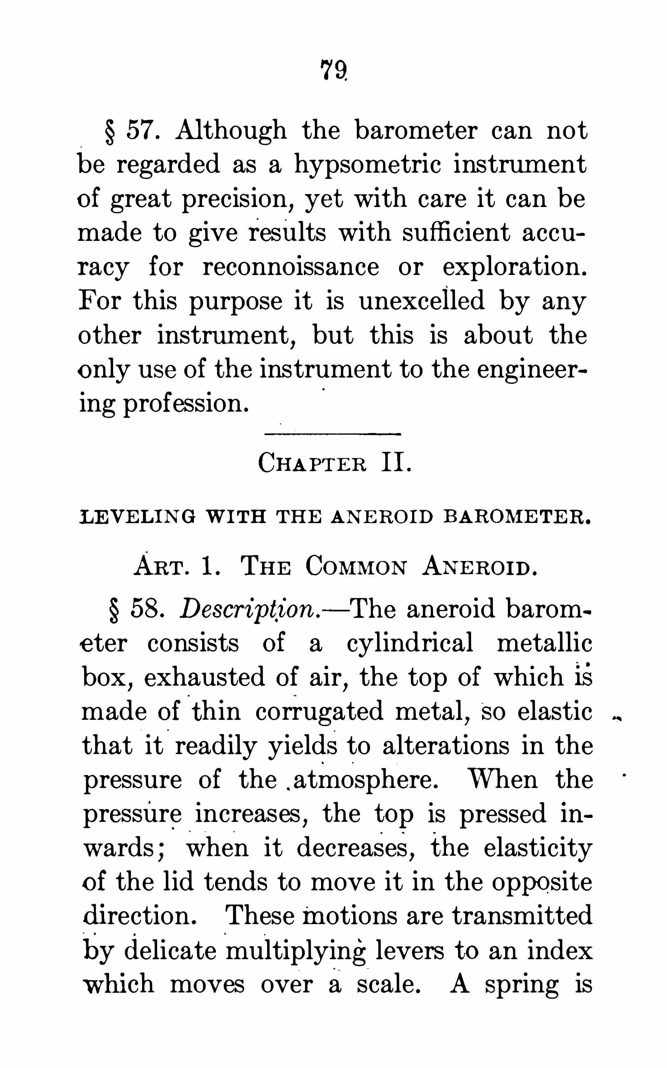
57. Although the barometer can not
be regarded as a hypsometric instrum ent
of great precision, yet with care it can be
made to give results with sufficient accuracy for reconnoissance or exploration .
For this purpose it is unexcelled by any
other instrum ent,but this is about the
only use of the instrument to the engineer
ing profession .
CHAPTER II.
LEVELING WITH THE ANEROID BAROMETER .
ART . 1 . THE COMMON ANEROID .
58 . Description — The aneroid barom
eter consists of a cylindrical metallic
box,exhausted of air
,the top of which is
made ofthin corrugated metal,SO elastic
that it readily yieldsto alterations in the
pressure of the atmosphere . When thepressure increases
,the top is pressed in
wards ; when it decreases, the elasticity
of the lid tends to move it in the opposite
direction . These motions are transmitted
by delicate multiplyinglevers to an indexwhich moves over a scale . A Spring is

80
sometimes ins erted between the two endsOf the vacuum chamber to reinforce the
elasticity of the corrugated ends . Some
times the vacuous box is not entirely exhansted
,the obj ect being that the enclosed
air may reinforce the spring,
“the air
gaining elasticity as the spring loses,with
in crease of altitude .
” It is at leastdoubtful whether the Spiral spring needs
assistance,and therefore whether the
air is of any benefit ; and it certainly in
troduces complications,owing to the
effect, of a change of temperature of the
enclosed air .
There are several forms of aneroids
which differ in the mechanism employed
to multiply the linear motion of the end
of the vacuous box and to convert it intoangular motion . Fig. 5 shows the mech
anism of a common form ; the outside case
and the front face of the vacuous box areremoved .
The instrument is graduated empirically by comparing its indications underdifferent pressures with those of a mer
curial barometer ; the scale is marked to


82
correspond to inches of the ordinary ba;
rometer colunm,the inches being divided
into tenths, "and the tenths usually into
four parts . At the back of the instrument is a little screw which presses agains tone end of the exhausted box
,by turn
ing this screw the index can be moved
over the scale,and the ins trument may
thus be made to.
agree at any time with astandard m ercurlalbarometer.
59. In many instruments there is an
additional scale Of. altitudes in feet gen
erally divided according to a table prepared for the purpose by Professor Airy .
Such a table could be prepared by usingany of the formulae discussed in the pre
ceding chapter by neglecting the correc
tions .
‘
Professor Airy used a formula
similar to and neglected the tem
peraturetern'
L When the aneroid has ascale of elevations engraved upon its facethe approximate difference of height is
Obtained by subtracting the reading infeet at the lower station from that at theupper.The use of such a scale leads only to

83
rough approximations,as it is based on
the assumption that certain differencesof pressure correspond at all heights withthe same differences of elevation . The
scale of elevations can only be correct atsome particular temperature, and hence
in general a temperature correction mus tbe applied . Some makers endeavor toeliminate this correction by making thescale movable .
“The movable scale is
uns cientific and inaccurate .
” The best
plan is to dispense with scales Of altitude,
whether fixed or movable,and calculate
the heights .
60. Defects — The aneroid is a veryconvenient instrument
,and for a Station
ary instrum ent where nice readings are
not required,it does very well ; but for
accurate hypsometrical results it is aninferior instrument . Its defects are1 . The elasticity Of the corrugated top
Of the vacuum chamber is affected by re
peated changes in pressure . This willproduce error in the scale readings .
2 . It is usually claimed that,in con
sequence of not completely exhausting

84
the vacuum box,the indications of the
aneroid become independent of the effectof changes of temperature of the instrument. The best that can be hoped foris that for small changes the temperaturecorrection is less than the error of observation . In instruments compensated for
temperature,the effect Of a
‘
change issometimes the same as that in the mer
curial barometer and sometimes the re
verse . The effect of the temperature on
any particular instrument can be deter
mined only by trial .
3 . The different spaces on the scale areseldom correct relative to each other
,
owing probably to errors Of observations
and graduation,and possibly to differ
ences of temperature and changes in elas
ticity. As a matter of fact,the scale is
often only a Scale of equal parts . The
barometer scale is more accurate thanthe elevation scale, since the latter has
all the inaccuracies due to the formula
by which it is graduated , in addition tothose of the instrument itself For accurate workthe aneroid should have a ther

86
somewhat ; that is, the ins trument runs
down . Before us ing the instrument,ex
perim ents should be made to determinethe range -of pressure to which it may beexposed before the Spring ceases to act .
In case an aneroid is to be used in ane levated regi on
,if there is a mercurial
barometer with the party,screw up th e
aneroid until the spring acts well and setit by the mercurial barometer
,SO that
there Shall be a difference of say one
or two inches between them .
§ 61 .
“With all these defects a goodaneroid 1s of much assistance on a survey
or reconnoissance in mountainous dis
tricts,
’on side trips of one or even severaldays’ duration
,when the instrument had
been previously. compared with a stand
ard mercurial barometer at various tem
peratures and in different elevations and
proper tables of corrections made . It is
evidently impo rtant that there should bea good attached thermometer . It should
be compared before and after it is usedin that way
,to ‘
see if the zero has notchanged in the meantime
,and if the

87
agreements are satisfactory the resultscan be relied upon .
”
62 . Formulae — From the readings of
the aneroid at two stations,the differ
ence of elevation may be d etermined by
any of the formulm of the preceding chap
ter,for any of the approxiinate formulas
are as accurate as the instrument . Amodification Of Babinet’s approximateformula (11) is most frequently used .
The following is a very common form :
H’ T— 55 XX 54
1
I l5450
10200
The last term is the supposed probableerror due to the varying dens ity of the
air column,and the preceding term that
due to the instrument itself. This formula is lim ited to difference Of heightsof about feet .
ART . 2 . THE GOLDSOHMIDT AN EROID .
63 . The comm on aneroid was in
vented by Vidi,of Paris
,in 1847
,and the
defects of its complex levers have long
William son on the Barometer.1' U . S . C . S . Report , 1876, p . 352.

88
been recognized . As early-asschmidt designed a form of aneroid which
FIG . 6.
to do away with the transmittingand multiplying mechanism of the Vidi

89
form . Figs . 6 and 7 are two views of oneof the latest forms of Goldschm idt’s ane
roids . Fig. 7 is a section through the com
FIG . 7
pound vacuum chamber ; the greater thenumber of boxes the larger the motion of
the index a. The relative position of the
movable index aand fixed point of refer
ence b is observed by the telescope L
(Fig. the distance being measured by

90
the micrometer M. The instrument is
very delicate 1n 1ts indications,but is lia
ble to serious disarrangement by ordinaryhandling . Different manufactures haves lightly different forms of the Goldschmidt
type,but all have essentially the same
defects— are not able to stand ordinaryuse .
It is doubtful if there is any advantagein an aneroid as complicated as that
shown in Figs . 6 and 7 ; it seems probable
that no form can be devised which shallbe both delicate in its indications and
able to stand rough handling . The chief
advantage Of the common aneroid is itsportability
,combined with moderate accu
racy. The mercurial barometer and the
aneroid supplement each other ; the first
is delicate and the second is portable . It
is doubtful if the two qualities can be combined in a Single instrument, or one Ob
tained more delicate or more reliable than
the mercurial barometer.

91
CHAPTER III .
LEVELING WITH THE THERMO-BAROMETER .
64 . Theory.
—When water is heated,
the elastic force . of the vapor produced
from it gradually Increases until it becomes equal to the incumbent weight Of
the atmosphere . Then,the pressure of
the atmosphere being overcome,the steam
escapes rapidly in large bubbles and the
water boils . Since the temperature atwhich water boils in the open air depends
upon the weight of the atmosphere col
umu above it, and as the0
weight of the
atmosphere decreases with the elevation,
it is Obvious that the higher the station,
the lower the temperature at which the
water will boil at that station . The tem
perature at which water boils under differ
ent pressures has been determined by ex
periment. It is then only necessary to
observe the temperature at each stationat which water boils
,and by referring

92
to tables Similar to the above,find the
corresponding height of the barometer,from which the difference Of elevation
may be computed by any of the formulae
previously given . Or the temperature
FIG . 8.
may be Observed at only one po int,and
by using the mean pressure at thelevel
,compute the absolute elevation.
Or, finally,if the effect Of ,
‘
variationsin temperature, moisture, pressure, etc

94
from pure water while boiling under at
mospheric pressure .
The general arrangement consists of a
closed vessel with a chimney with a combination of passageways for the exit of
the steam,somewhat like Fig. 8 . The
bulb of the thermometer is thus immersed
in a current of steam . The double pas
sageway is to prevent condensation on
the inner walls of the flue .
66. Defects — The chief difficulty is
in ascertaining with the necessary accuracy the true temperature Of boilin g
water ; an error of TI, Of a degree centi
grade would cause an error of 70 to 80
feet in the fi nal result . An observationof the boilin g-point
,differing by
Tl, of a
'
degree from the true temperature,ought
to be considered a good one . The accu
racy is dependent upon the accuracy and
sens itiveness of the thermometer,and is
affected by the quality of the glass Of the
thermometer,the form and substance of
the vessel containing the water,the purity
of the water,the place at which the bulb
of the thermomete r is placed,whether in

95
the current of steam or in the water,the
error of reading,displacement of zero
point,etc .
Even if the above errors did not exist,
this method would still be subject to all
the chances of error which affect the
measurements of heights by the barom
eter .
Nor is the thermo-barometer as con
venient as either the aneroid or mercurial
barometer,owing to the time required to
s tart a fire,boil the water
,make the Ob
servation, and wait for the instrument to
cool,and the difficulty of Obtaining pure
water . Also,altogether the apparatus
makes quite a load to be carried fromplace to place .
Since(the invention of the aneroid the
method ofmeasuring heights by the tem
perature Of boiling water has almost been
abandoned .

96
CHAPTER IV.
TRIGONOMETRIC LEVELING .
67. Principle.
— Trigonometric leveling consists in determining the differenceof level of two stations by means of themeasured angle of elevation or zenith dis
tance Of one and the known horizontal
distance between them . The horizontal
distance is usually given by triangular
tion .
This kind of leveling is peculiarly Suitable for finding the heights of the sta
tions of a triangulation survey,since the
extra labor required to measure the necessary vertical angles is but slight .
68 . Observations — The vertical angles
are measured at the same time and with
the same instrument as the horizontal
angles . The instrument should have twoopposite verniers or micrometer micro
scopes and a sensitive level in a plane
parallel to the vertical circle . It should
be carefully adjusted for collim ation, ver

98
as to obtain different conditions of the
atmosphere rather than to take any great
number of success ive Observations .
69. Refraction — Since the effect of
atmospheric refraction is to elevate oh
jects on the horizon,a correction for
refraction must be added to the zenith
distance as measured above . The uncer_
tainty as to the amount of this correction
is the great cause of inaccurate work in
trigonometrical leveling . Refraction is
so erratic in its character that no satis
factory method has yet been devised for
determining it . The best that can bedone is to Observe only when the refrac
tion has its least effect .
Therefore,since the accuracy of trig
onom etrical leveling is limited by our
knowledge Of the laws of atmospheric
refraction,it will be necessary to investi
gate that branch before proceeding with
tlie general subj ect .
ART . I . COEFFICIE NT OF REFRACT ION .
70. Defi nition — The angle of refrac
tion divided by the arc Of the earthfs

99
c ircumference,intercepted between the
observer and the station observed, is
called the coefi‘ici ent of refraction .
* That
is,if O= the angle at the center of the
earth subtended by the two stations,F=
the refraction angle and m = the coeffi
cient of refraction,then m
F.
-C canC
be found in are from the expression10
CPsin 1
1 1 7
between the two stations and p is the
radius.
of the earth .
71 . To Find the Coefiicient — The co
efficient of refraction may be found ineither of two ways
,viz . : I
,from recipro
cal zenith distances ; Or,II
,from the Ob
served zenith distances of two stations,
the relative altitudes of which have been
determined by the Spirit-level .
72 . I,ByReciprocalZenithDistances .
— In Fig. 9,if A and B denote the posi
in which 10 is the distance
In the reports of progress of the U . S . Lake Surveyand in Wright’s Adjustm ent of Obse rvations a defi nition is given which makes the coefficient of refractiontwice as large as the above . The defi nition as abowseem s to be the one m ore frequently used .

100
tions of the two stations,the angles which
the observers attempt to measurePAB and QBA. On account of the
FIG. 9.
fraction of the atmosphere, the of a
ray of light from B to A will not be astraight line
,but some curve more or less

102
r efraction which is found to exist, even at
the same moment,at two stations a few
‘miles apart . The observations should be
simultaneous or nearly so . Under these
conditions the coefficients at the two ends
of a line become equal ; i .e .
,in the pre
‘ceding formulae m’=m . The error in
this assumption will be greater as the
distance between the stations is greater ;it also increases very rapidly with the dif
ference in elevation .
Making this substitution (19) becomesI
mZ+Z
C
180(20)
73 . II,By zenith distances
,the difi er
ence of level being known — There are twocases : (1) single zenith distances and (2)reciprocal zenith distances .
(1) Measure the zenith distance of thes tation
,and from the known difference
o f level compute the true zenith distance ;the difference between the true and
c omputed zenith distances is the refrac
tion angle,which
,divided by the sub
tended angle,is the coefficient sought .
U . S.
'
C . G . Report , 188 2. p . 182 .

103
From Fig; 9,
CB AC h’ h
GB AC 2p+h’+h
tan . % (CAB CBA)tan . (CAB CBA)
CAB 180°
z — mc,
CBA z+mc 0 .
Substituting and reducing,h’— h
2m
p+hf
+hcot (2+mC — 750) tan . to
Developing tan . 5G by
tan . x= x+x
etc .
3
and substituting G=ij, we geth’— h= k cot .
~(Z4—mC —170)h’ h k2
1+2
+
p
Z+mC — w"= oot 1h
gh '
h’ -h k2
from which m can be found .
(2) Also CBA= 180° sub
stituting this value in remembering

104
that and Z+mC=Z0 and
solving as before we get
h’— h
k
h'— h kz
“T oZ0) 90
0
+ “ic
ZO— Z=F and Z
’
O
F F'
and finally mUand m
C
Struve,T Bauerfi end, and others have
deduced rational formulas for computing
the coefficient of refraction from the ob
served temperature and barometric pres
sure,but such formulas are of little utility
,
owing to the difficulty in the way of getting the temperature and pressure of the
atmosphere .
§ 74 . Laws of Refraction . Experi
ence has proved that the refraction is
greater and more variable at sunrise thanat any other hour of the day ; that it
gradually diminishes in both respects,
Z0) tan .
" 1
U . S . C . G . Report , 188 2, p . 183 .
1‘
British Ordnance Survey, p . 2 14 .

106
temperature,but increases with increas
ing atmospheric pressure ; in general itsvalue depends upon the law of the distribution of temperature with the height .
”
There is an irregular effect of refrac
tion,usually termed “boiling
,
” due to
varying dens ity of the atmosphere,which
causes the target to vibrate rapidly
through a small angle rarely exceedingbut whose effect cannot be calcu
lated .
For a table showing the diurnal variations of refraction see U . S . C . G. Re
port,1876, pp . 361—2 ; also U . S . C . G.
Report,1883
,pp . 295 and 310.
75. V alue of the Coeflicicnt
De Lambre,from observations in
France — 1
Begat’s Trait" de Geodes ie, in
France, for Summ er
Begat’s Trait" de Geodesie, in
Fran ce,forWinter
Begat’s Trait" de Geodes ie, in
fi an ce, for m ean
U. S . C . 8 . Report .

107
Bessel, from Operations in Prus3 1a — 3u u a
_ 3
Struve, Russia.
— 3
Corabeuf,
Mean ‘
from all observations inFrance
Chauvanet givesThe British Ord. Survey . .0.0768 i 0.0035
Do . for rays not crossing the sea.
crossing
U. S. C. S. in New England near the
— 5
U. S. C. S. in New England for
small elevations — 5
U . S. C. S. in New England between
primary stations .
— 5
U . S. C. S. in in terior of coun try .
— 7
U. S. Lake Survey in Central Illino is
1 . Chauvenet’s Prac tical Astronomy, Vol . 1 , p . 177 .
Davies and Peck’s Mathem atical Dictionary. p . 20.
Ordnance Survey, p . 512 .
U . S . Lake Survey Report , p . 428 .
U . S . C . R . 1868 .
Clarke’s Geodesy, p . 283.
U . S . C . S . 1868 , p . 62 .fl
Ofi
O‘
rh
OO
N
ART . 2 . TRIGONOMETRICAL LEVELING .
76. By Observed Angle ofElevation .
Let D,Fig. 10
,represent the position of
the observer,and E the station whose

1 08
elevation is to be determined . Let Athe observed angle expressed in secondsof arc ; k= the distance between the sta
tions .
The difference of level,dh
,is made up ofHF
,due to curvature
,and FE
,due to the "
angle of elevation. The angle of refrac
ktion EDB=mC=m The true
p are 1

1 10
The last term is plus for angles of elevation . The chief source of error in thisas in all other formulas for trigonomet
rical leveling 1s in m .
FIG. 1 1 .
77. By the observed zenith
of the sea Z= the measured zenith distance
,h
.
= the elevationsought . Then in Fig -
11

1 1 1
1 — cos . C
o+h°
2p sin .
2
£0 20 sin . $0 sin . C
cos . C 2 cos . 50 cos . C
p tan . %0 tan . C .
Since G is always small , assume tan . $0
tan . C, which, substituted above,
gives
h tan .
2 C.
To find C,noti ce that Z+mC+ (90— C)
therefore C=71
119
72 whi ch, sub
stituted in the above, gives
2Z— 90° ph= %p tan .
1 _ m mtan .
2
(Z (30)
78 . By the zenith distance observed at
one station — Let dh= the difference in
level between the two stations . The tri
sm . ABD
ABD=Z+mC— CBAD= 90°— (Z
U. S. C . S . Report , 1868. p . 127.

1 12
cos . (Z+mC — %C)dh=k
sin . (Z+mC— C)
79. By to
eliminate refraction — Let Z and Z’be
U . S . C . S . Report, 1868 . p . 126.

1 14
should be measured and made a part of
the record .
The correction to the zenith distancefor the difference in height of the target
and telescope above the ground may be'
computed by the formula : correction in
s econds= —.
j —7, in which d is the dif
k sm . 1
ference in height and k is the distancebetween stations .
§ 82 . Limits of Precision — Reciprocal
z enith distances measured at any two stations at the same moment of time
,or
under the same supposed condition of
atmosphere,give the best results When
reciprocal,but not simultaneous
,the ob
s ervations should be made on different
days,as in the case -of horizontal angles
,
in order to obtain as far as possible a
mean value of the difference between therespective angles and an average value of
the refraction . The same care should be
taken when -the zenith distance is measured at one station only .
The condition of the atmosphere andthe relative refraction may be so different

1 15
at stations situated more than twentymiles apart, that, as a general rule, the
difference of level determined even by re
c ipro cal observations cannot be relied
upon for the des ired degree of accuracy
at distances greater than about twenty
miles,unless a very large number of
measurements have been made,under
the most favorable circumstances . Notice
that the difference of height determined
by trigonometrical leveling depends upon
the coefficient multiplied by the square of
the distance,and that
,therefore
,there is
a lim it to the distance for which any as
sumed mean coefficient can be dependedupon for accurate results . The higher
the elevations,the more reliable the re
sults .
§ 83 . In the final report of the U . S .
Lake Survey (p . 544) it is stated that the
probable error of determining a differenceof level in Eastern Illinois by reciprocalzenith distances
,using 8 to 10 separate
meas urements,made on 2 to 6 days
,over
lines 16 to 20 miles long,was somewhat
less than 1 foot .

1 1 6
The U . S. C . G. S . Report,1876, p .
345,contains an account of trigonomet
rical leveling in California,over a line 14
miles long,in which the mean probable
error of reciprocal zenith distances,1 1
hourly observations on 5 successive days,
was meter in 600 meters ; for single
zenith distances the error was meters .
The same volume contains an account of
angular leveling in Georgia,in which
(p . 379) it is stated that the probable
error per line of about 20 miles is .487
meter orWof t he horizontal dis
tance .
Probably the above may be cons idered
as examples of the best work possible .

1 1 8
or English instrument is a type . The thirdincludes all instruments whose errorsof adjustment can be wholly eliminatedby a system of double observations . The
levels employed in geodesic leveling areof this class and are generally known aslevels of precision .
There is considerable variety in the
form of this class of levels,but only two
have been used to any cons iderable extent in this country— the Swiss or Kern
level,by the Lake Survey andMiss issippi
River Commission,and a modification of
the Vienn a or Stampfer level,by the Coast
and Geodetic Survey . The cons truction
of the two are similar,hence only the
latter will be described here . The formeris described in the final report of the U .
S . Lake Survey,p . 597
,and described
and illus trated in Jordon’s V erm essungs
kunde,vol . I.
,p . 404 .
§ 86 . U. S. Coast Survey Level— The
instrument is shown in Fig. The
telescope may be reversed end for end
and revolved about its Optical axis the
From U . S . C . S . Rep ort . 1879. p . 202.

1 1 9
two positions in which the horizontal
thread is horizontal,being definitely fixed
by proj ecting pins . The level can also
be reversed end for end independent of
the telescope . One end of the telescopeand level can be raised and lowered bythe micrometer screw . Near the m icrom
eter is a cam-hook,by which the weight
of the superstructure can be raised off
the micrometer during transportation .
Under the telescope are two false wyeson lever arms by which the telescope can
be raised out of the wyes for transporta
tion . The whole ins trum ent is secured
to the tripod head by a brass plate whichfits over the feet of the leveling screws .
The aperture of the telescope is 43 mm .
(1% inches nearly) , focal length 410 mm .
(165 inches nearly) , magnifying power
37. The value of one millimeter of thelevel scale is 1 .5 (1 inch= 37” .5 or
radius= 800 feet) . The diaphragm is
glas s and has two horizontal and one vertical line ruled upon it . The two horizontal lines
,are used as stadia hairs todetermine the length of sight .

120
Asmaller size of this instrument is alsoused . The weight of the larger one
,in
clusive of tripod,is 45 lbs . ; the smaller
weighs 23 lbs .
§ 87. The Rod — The rod used with
this instrument was a target rod made ofpine
,3” by stiffened by a strip fast
ened along the middle of each face . One
edge of the main strip has a self-reading
graduation to cm . upon it . Abrass strip,
graduated to cm .,is let into the side of
the strip ; it extends the whole length of
the rod,being
‘
fastened immovably at
the middle . Its temperature is determined by a thermometer let into the sideof the wood . The target
,which is moved
by an endless chain,carries a short ivory
scale,graduated to mm .
,which slides
over the brass strip ; the rod thereforereads to m illimeters . The foot of the
rod is a rounded piece of brass resting ina corresponding depression in the foot
p1ate .
* Ahandle and a disk level enablethe rodman to keep the rod vertical .
Would it not be better if the end of the rod werehollowed out to fi t a projection on the foot plate"


122
back and foresights . But to employ—the
check of double leveling (as will be de
s cribed presently) , a correction for inequal
ity must be applied to the rod reading .
The inequality of the collars can be de
termined by observations with a striding
level,exactly as the pivots of an astro
nom ical transit are examined ; cons e
quently it is unnecessary to describe the
method here (see Chavenet’s Practical
Astronomy,vol . II .
,p . 153
,or U . S. C .
G . S. Report,1880
,p . The correc
tion to be applied to the rod reading at the
d istance D will be d sin . in which
d is the pivot correction in seconds of
arc .
90. The absolute value, and the uniformity of the graduations of the rod
,the
coefficient of expans ion,the accuracy of
the thermometer,and the disk level
should be tested carefully The observer
should also know his ordinary inaccuracy
in performing the different parts of an
observation .
91 . Correction for Curvature and Re
fraction . Curvature — To compute the

123
correction for curvature,let AD
,Fig.
14,represent the line of apparent level
,
and AB the true level . DB is the correcti on for curvature . By GeometryAD2=DB(2BC+DB) . Neglecting DB
,
FIG . 14.
as it is very small in comparison with2BC
,and repres enting the length of
sight by k,and the radius of curvature
by p, then correction for curvature2
BDk
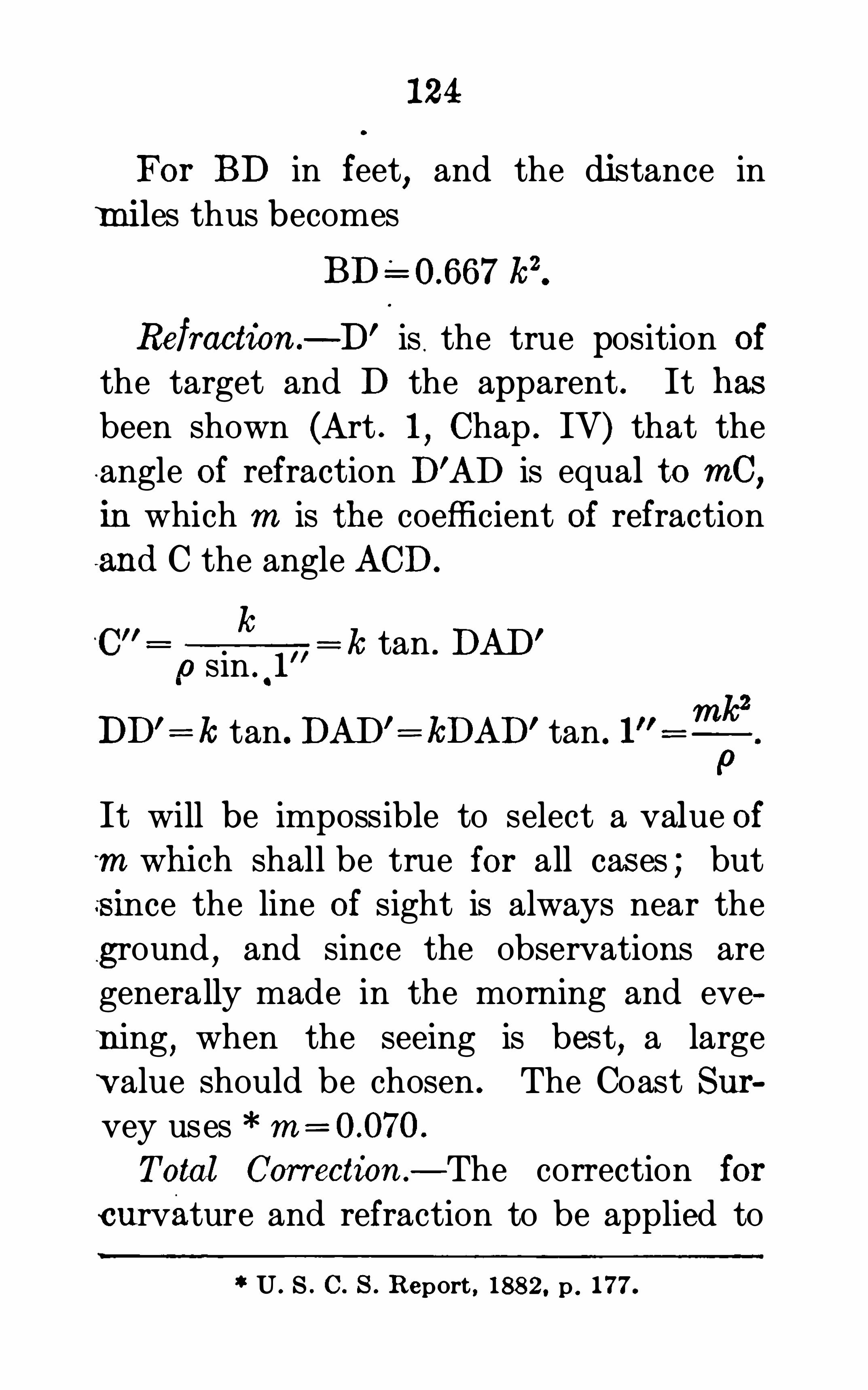
124
For BD in feet,and the distance in
m iles thus becomes
BD kz.
Refraction .— D’ is
.the true position of
the target and D the apparent . It hasbeen shown (Art . 1
,Chap . IV) that the
angle of refraction D’AD is equal to mC,
in which m is the coefficient of refractionand C the angle ACD.
h_
,o sin .
.1
DD'=k tan .DAD’= kDAD’tan . 1
= k tan . DAD’
mic2
P
It will be impossible to select a value of‘m which shall be true for all cas es ; buts ince the line of sight is always near the
ground, and since the observations aregenerally made in the morning and eve
n ing,when the seeing is bes t
,a large
value should be chosen . The Coast Survey uses m = o.070.
Total Correction — The correction for
curvature and refraction to be applied to
U . S . C . 8 . Report , 188 2, p . 177.

126
ment ; A,,A2, etc .,successive positions of
one rod ; and B1 ,B2, etc .
,successive posi
tions of the second rod .
I is the method of ordinary leveling,
and may be called single kveling with o ne
rod.
0
II is single leveling with two rods . By
the use of the two rods,less time inter
venes between the backsight and fore
sight ; it is therefore more accurate, asthere is not so much liability of change
in the plane of the line of sight . It is alsomore rapid than with a single rod . Thisis the method used on the U . S . Lake
Survey,* and the Mississippi River Surveys .TIII
,double leveling with one rod
affords a perfect check against errors of
adjustment and observation,since the dif
ference in reading of the two foresights
should be the same as the difference of
the two backsights following .
IV,double leveling with two rods
combines all the advantages of II and III.
Chief Engineer’s Report , U . S . A. , 1880, p . 2427.
1“Miss iss ippi R iver Comm iss ion Report , 188 1 .

127
It is the method used on the U . S . C .
G . Survey .
* The num erals adj acent to
the rods show the order in which they
are sighted upon .
V,duplicate leveling, is another method
sometimes us ed . Two rods are used,be
ing placed as in the figure . After havingobserved upon AI and B1 the instrument
is pulled up and reset a little to one side
and the two rods sighted upon again .
This method duplicates the work as far
as instrum ental errors are concerned,but
is not an independent check .
§ 93 . The Observation — After having
planted the tripod firmly and leveled the
instrument,read both ends of the bubble
,
estimating the fraction of a division ;next read the position of the two (or
three) wires on the rod ; then read thebubble again for a check to eliminate anychange . Reverse the level end for end
,
and turn the teles cope 180° about its
Optical axis , and repeat the operations
as above . The first reversal eliminates
any inequality in the lengths of legs of
* U . s . C . G . 8 . Report. 1879, p . 206.

1 28
the striding level ; the second eliminatesany error of collimation . The mean of
the several readings must be corrected forthe difference in position of the bubble
,
and for inequality of the collars .
Instead of reversi ng the level and
telescope at the same time,the observa
tions are sometimes made as follows
Read upon the rod,reverse the level
,and
read again ; .reverse the telescope and
read a third time,then reverse the level
and make a fourth reading . The first
method seems the better .
94 . If there is a milled head screwunder one end of the telescope
,the bub
ble can easily be brought to the middleeach time ; if there is not, it is better to
bring it nearly to the middle and apply a
correction . It is not enough to read only
one end,since the bubble is liable to
change its length with a change of posi
tion or temperature .
95. On the coast survey the method
of observing differs slightly from that
described above .
* E rrors of level and
U . S . C . 6: G . S . Re port, 1879, p . 206.

1 30
collimation are eliminated by reversingbubble and telescope on each backsightand foresight ; but each observation is ofa single wire on a target . The target isset but once for each station
,the differen
tial quantities being read by the micrometer under the eye end of the telescope .
This seems not to be as good a methodas the above ;
“there are two obj ections
aside from the time and labor required to
set the target . First,there is no suffi
cient check agains t errors in reading thepositions Of the target . Second
,the
micrometer is read for a central position
of the bubble,the telescope is then moved
to bisect the target and the screw read
again,therefore there is no check on the
stability of the instrument .
”
§ 96. Length of Sight — On the U . S.
C . G. Survey,the length of sight ranges
from 50 to 150 meters,according to con
dition of ground and weather,the aver
age being 1 10 meters,the distapce be
tween the two rods on the same side of
the instrum ent being 20 meters . On the
Lake Survey,* the maximum was 100
Final Report, p . 598 .

1 31
meters ; on the Prussian Land Survey,
since 1879,it has not exceeded 50 meters,
except for river crossings .
*
The attempt is always made to placethe instrument half way between the two
stations ; the rodman approximates thedistance by stepping
,and the instrument
man measures it by the stadia hairs . On
the Lake Survey,the difference between
corresponding back and foresights wasnot allowed to exceed 10 meters .
97. Sources ofError .
— Probably in noo ther kind of ins trumental engineering is
it as important to distinguish between
compens ating and cumulative errors,as
in leveling . For convenience in discussing them
,we shall classify errors of lev
eling as follows : 1,Instrumental Errors ;
2,Rod Errors ; 3, Errors of Observation ;and 4th
,Personal E rrors .
1 . Instrumental Errors — The principal instrumental error is due to the line
of sight not being parallel to the level,which may be caused by imperfect adjustment
,or unequal size of rings
,or
Wright’s Adjustm ent of Obse rvations . p . 375 .

1 32
bo th . If the telescope slide is not
straight,or does not fit snug
,it will
'
also
produce an error. Of course the instrument must be focused So as to eliminateparallax All of these errors are c limi
nated,whatever their value
,by set
ting the instrum ent midway between theturning points .
It has been found that appreciable er
rors are caused by the settlin g of the in
strument on its vertical axis,and of the
settling of the tripod legs into the
ground ; in spongy or clayey ground
the tripod legs are sometimes gradually lifted up . These errors
,though
small in themselves,are more im
portant than is generally supposed,
inasmuch as they are cumulative ;but probably they would be appreciableonly in precise leveling . They can be
eliminated by running the line in the op
posite direction .
A small source of error arises from thefact that the adhesion of the liquid to the
sides of the glass tube prevents the bubble from coming precisely to its true

1 34
inated by noticing the position of thebubble after setting the target
,and can
be still further reduced by shading theinstrum ent . The Indian Geodetic Survey proved conclusively that the error
was appreciable even when the instrument was shaded .
*
2 . Rod Errors — The principal rod er
ror is in not holding the rod vertical ; this
may be remedied by attaching a level or
by waving the rod . In waving the rod,
care must be taken that the front face isnot lifted by resting upon the back edge
when the rod is revolved backward .With telescoping target rods when extended
,the slipping of the upper piece
,
after the target has been pronounced correct and before the vernier has been read
,
is a source of error . The target itselfmay slip
,but this is not so probable
, be
cause of its less weight .
An other source of error is the settling of
the turning point,due
,in coarse or sandy
soil,to its own weight, or to the impact of
setting the rod upon it . The resulting
Jackson’s Aid to Survey Practice. p . 18 1 .
135
error is cumulative . The remedy in thefirst case is to use a long peg
,or to rest
the rod upon -a triangular plate with thecorners turned down slightly
,or with
Spikes on the under side . This foot
plate with a convex button attached,on
which to place the rod,is better than a
peg for all cases . Whatever the turningpoin t
,the rod should never be dropped
upon it .
Finally,another small rod error is the
error in the graduated length . This
affects only the total difference of eleva
tion between the two points . This is a
much more important . source of error
with the numerous home-made self-read
ing rods now in use,than with the rods
made by regular Instrument makers .
“An important source of error in spiritleveling
,and one very commonly over
looked,is the change in the length of the
leveling rod from variations of tempera
ture . It is quite possible that errors
from this source may largely exceed theerrors arising from the leveling itself.”
Wright’s Adjustm ent s of Observations, p. 372 .

136
3 . Errors of Observations — The prin
cipal error of observation is in reading
the position of the bubble ; even if the
bubble is kept in the middle,it is never
theless read . Everv leveler should
know the error on the rod corresponding
to a given distance of reading of the
bubble ; he then knows how accurate ly
he must .read the bubble for a given de
gree of accuracy in the results .
Another source of error is the movingof the bubble after being read
,and before
the sighting has been made . This move
ment of the bubble may be caused by itsbeing read before it has come to rest
,by
disturbing the instrum ent by steppingnear the tripod legs
,by turning the in
strument slightly in azimuth,or by raising
or lowering one end of the telescope in
focusing,or by the action of the sun or
wind . The bubble should be re—read
after the target is nearly adjusted,or
with a self-reading rod,after the reading
has been m ade and before the rodman is
signaled to move on . These two prob
ably constitute the chief sources of error
in leveling operations .

1 38
each hair and the mean used as the rod
reading . For a single observation,a tar
get rod is more accurate than a self-read
ing one ; but three observations as above
are probably more accurate than a singleobservation upon a target
,and can be
made in about the same time .When very long sights are required tobe taken with the level
,another source of
errormust be cons idered,viz .
,the curva
ture of the earth and refraction . Owing
to these two causes,a point 220 feet dis
tant appears about ft. too high ; this
error increases as the square of the distance . It is wholly eliminated if the instrument is always exactly half-way between the turning points . Refraction is
not always the same ; its mean effect wasused in finding the above correction .
Consequently,if there is abnormal re
fraction or a change of refraction be
tween sights,
or . a tremulousness or“boiling ” of the air
,small errors may
result . The only remedy is to shorten
the length of sight,or wait for better
atmospheric conditions . The atmosphere is

139
usually in the best condition for seeing justbefore sunrise and a little while before sunset
,although the refraction is then greater .
A cloudy day is better than a clear one .
There is a possibility of error in record
ing the observations and making the
computations,but in precise leveling
there are so many checks that there is no
,probability for serious error in this respect .4 . Personal Errors — The errors pre"
viously described are liable to occur withany observer ; they are due chiefly to the
instruments and to the nature of the work,
and would probably not materially differ
for equally skilled observers . We comenow to a class of errors which dependmainly upon inaccuracies peculiar to theindividual .With a target rod, errors of one foot
and one-tenth are not uncommon . Theonly check is for the rodman and observer
to read it independently and comparenotes ; but this is inconvenient and not
always possible . With a self-reading rodthis error is less liable to occur, especially
if three hairs are read .

140
Finally,each individual has errors
peculiar to hims elf,or to the work he is
doing . One may read a target higher or
lower than another of equal skill ; or
one observer in reading the position of
the bubble may have peculiar views as to
what constitutes the end of the bubble,
or he may habitually read the bubble so
as to get a distorted view of it throughthe glass tube ; errors from these causes
are compensating . Again,the target
may be better illum in ated on foresightsthan backsights
,as in working toward or
from the sun ; in this case the error will
be cumulative .With skillful observers, all such errorsare quite small and generally cancel them
selves . In fact,the errors here classed
as personal are possible rather than
demonstrated as actually occurring ; and
yet,there is nothing more certain than
that in any series of accurate observations,
there is a difference between the results
of different individuals . This difference
is known as personal equation . In long
lin es of accurate leveling,it has been

142
tion, as is done in India . It may be still
further increased by reading the back
sight first at each alternate time the in
strument is set up .
The effect of this class of errors may
be eliminated by each observer duplicatingthis work in the opposite direction un
der as nearly the same conditions as
possible .
§ 99. Limits of Precision —The prob
able error per unit of distance is gener
ally adopted as a convenient measure of
the precision reached . According to the
theory of probabilities,the final error of
a series of observations,afi ected only
by accidental errors,will vary as the
square root of the number of observations ; hence the error of leveling a num
ber of units of distance is assumed to
vary as the square root of the distance .
This as sumption would be true if accidental errors were the only ones made
,
and if the number of observations were
strictly proportional to the distance lev
eled, i .e.,if the length of sight were
constant ; but in the preceding article it

143
was shown that leveling is afi ected by anerror which is nearly proportional to the
distance . It has frequently been noticed
that,cons idered individually
,the errors of
a number of short lines were well within
the limits which were prescribed to varyas the square of the distance
, yet when
the sum for several lines were considered
the total discrepancy would exceed thelimit . In other words
,for a line leveled
in only one direction the error is not
s trictly proportional to the square root of
the distance One part of the error is
proportional to the square root of the
distance and another portion varies nearly
as the distance . Hence the shorter thedistance
,the easier to attain a limit pre
s cribed to vary as the square root of the
distance .
“According to the Geodetic As sociation of Europe
,levels of precision exe
outed of late years in Europe, show that
the probable error of a line of levels of
precision should never exceed
ft.

144
is tolerable, 2 dist . in km . is a fair
precision .
” The Coast Survey requires
Of late years the Coast Survey’s andMississippi River
,
Survey’s work are considerable within the limit of
2 kilom . The Missis sippi RiverCommission’s limit is
5"/kilom . ft. V miles ) .“The
limit on the British Ordnance Survey isft. per mile .
”
Results of leveling are often given of
apparently greater accuracy than the limit
above ; but regularity of result and even
ness of error is of more importance thanoccasionally small disagreement . It is
usually the latter that is recorded .
If the error was determined by dupli
eating the work in the same direction, and
especially if at the same‘
time,as by
methods III,IV
,or V
,the difference will
U . S . C . 8 . Report, 1882 , p . 522 .


CATALOGUEOF
"THE
SCIENTIFIC PUBLICATIONS
D. V AN NOSTRAND COMPANY,
23MURRAY STREET AND 27 WARREN STREET, N . Y.
A. B . C . C ODE . (See C lausen-Thue .)
AB B O T T (A. The E le c trical Transm iss ion ofEnergy. A Manual for the Design of E lectricalCircuits . Fourth edition, revised . Fully i l lus trated .
8vo , c loth $4 50
AB B O T (G e n’l HE NR Y The Defence of the
Seacoas t of the United States . Lectures del iveredbefore the U. S. Naval War College . 8vo , red c loth . 2 (fl
ADAMS (J . Sewers and Drains for PopulousDistricts . Em brac ing Ru les and Formulas for thedim ens ions and construction of works of San itaryE nginee rs . Fifth edition. 8vo , c loth .
AI . CODE . (See C lausen-Thue.)
AIRMAN (C . M., Manures and the Principles of Manuring.
ALE X ANDE R (J . Universal Dictionary ofWe ights andMeasures ,Anc1eni andModern , reducedto the Standards of the United States of Am erica .
New edition , enlarged . 8vo , c lothALE X ANDE R (S . Broke Down : What ShouldI Do" ARead Refe rence and Key to Locom otiveEnginee rs an Firem en RoundHouse Mach in ists,C onducto rs . TrainHands and Inspectors . With 5folding plates . 12m o ,
ALLE N (C . Tables for Earthwork Computation.BV O, cloth o o o o o o o o o o o o 0 o o o o o o o o o o o o o

D. V AN NOSTRAND COMPANY '
S
ANDE R SO N (J . The Pros tor’s Hand-book ;A Guide for the Pros tor at: Traveller in searchofMetal-bearing or ot er ValuableMinerals . Seventhedi tion, thoroughly revised and much enlarged . 8vo ,
ANDE R SO N (WILLIADI) . On the Convers ion ofHeat intoWork. A PracticalHand-book onHeatEngines . Third edi tion . Il lustrated . 12mo , cloth . 2 25
ANDE S (LO UIS) . Vegetable Fats and O ils ; theirPracticalPreparation
,Purification and Em ploym entforvarious purposes .
'
1 he irProperties . Adulte rationand Examinat ion . AHand-book for O ilManufacturets and Refi ners , Cand le , Soap and LubricatingOilManufacturers and the Oil and Fat Industry ineneral. Trans lated from the German . With 94lus trations . 8vo , clothAnimal Fats and Oils . The ir Practical Production,
Purifi cation and Uses for a greatvariety of purposes,the ir Properties, Fals ifi cation and Exam ination . AHand-book for Manufacturers of Oil and FatProducts , Soap and Cand le Makers , Agriculturis ts ,Tanners , etc . Trans lated by Charles Salte r. Wi th62 illus trations . 8vo , ne t 4 00
AR NOLD (Dr . Amm onia and Amm oniumCom pounds . A PracticalManual forManufacturers ,
ChemiSlS, Gas Engineers and Drysalters . Secondedition . 12m o, c loth . .
AR NOLD ArmatureWindings of DirectDynam os . Extens ion and Application of a Genera lWinding Rule . Trans lated from the original Ge rm anb Francis B. DeGress , M. E . With numerousustrations .
ATKINSON (PHILIP) . The E lem ents of E lectricLightin includin E lectric Generation . Measurem ent, to e , an Distribution . Ninth ed ition .
Fully revise and new m atte r added . Illus trated12111 0 , clothThe Elem ents of Dynam ic E lectricity and Mag
netism . Third edition . 120 i llustrations . l2mo ,o o o o o o o o o o o o o o

D. V AN NOSTRAND COMPANY’S
BAR NARD (F . A . P .) rt on Machinery andProcesses of the Industria Arts and Apparatus ofthe Exact Sciences at the Paris Un ivers al Expo sition, 1867. 152 il lustrations and 8 fold ing plates8vo , cloth
BAR NARD (JOHN The Naval Mi litiaman ’s
Guide . Full leather, pocket form .
BARWISE (SIDNE Y , M. D., Lo nd on ) . The Purifi cation of Sewage . Be in
ga brief acw unt of the
Scientific Principles of ewage Purification andthe ir Practical Appl icat ion . 12mo , cloth . Illustrated . 2 00
BAUME IST E R The C leaning and Sewage ofCities . Adapted from the German w ith perm iss ionof the author . By J. M. Goode l l , C . E . Se condedition , revised and corrected , together w ith anaddi tional appendix . 8vo , c loth. Illus trated . .
BEAUMO NT (R O B E R T ) . Color inWoven Design .With 32 Colored Plates and num erous original illustrations . Large 12m o
B EAUMO NT ,W. a n d DUG ALD CLE R K . Autocars andHorse less Carr iages .
BE CKWITH(AR THUR ) . Pottery . Observationson the Mater ials and Manufacture of Terra-Gotta ,Sto neware . Fire-Brick , Porce lain . Earthenware ,
Brick, Majol ica, and Encaustic T i les . 8vo , paper .Second edi tion .
BE BNTHSE N A Text-Book of Organic Chem istry . Trans lated by GeorgeM’
Gowan , P11 .D. FourthEnglish ed ition . Revised and extended by authorand trans lator . Illus trated . 12m o , cloth
BER T IN (L. Mar ine Boilers : Their Construction andWorking, dealing m ore e specially withTubu lous Bo i lers . Trans lated by Le sl ie S . Robe rtson ,U ward of 250 i llus trations . Preface by S irWi ll iamn ite . 8vo , cloth .
I IGGS (C .H. First Principles of E lectricityand Magnetism . Be in an attem pt to provide anE lementary Book fo r t ose intending to enter tue
profess ion of E lectrical Enginee ring. Second editionRmo, cloth. Illus trated

SCIENTIFIC PUBLICATIONS.
B INNS (CHAS. Manua l of Practical Potting.
Compiled by Expe rts . Third edi tion , revised an l
en larged . 8vo , c loth . . ne t 7 50
Ceram ic Technologygy; be ing som e aspects of Techn icai Science as appl ied to Potte ry Manufacture .
8vo , cloth ne t 5 00
B LAK E (W. Report upon the Precious Me tals .
Be ing S tatistical Notices of the Principal Gold andSi lver producing regions of the world ,
representedat the Paris Un iversal Expos ition . 8vo cloth
B LAK E SLE Y (T . Alternating Currents o f E lect ric ity. For the use of Studen ts and E ngine e rsThird edi tion , e n larged . 12111 0 , c loth
B LYTH(A .WYNTE R ,M. R . C . S. , F . C . Foodsthe ir Com pos ition and Ana lys is . A Manual for theuse of Analytical Chem is ts , w ith an Introductory E ssay on theHistory of Adul terations , w ith num eroustables and il lustrations . New ed it ion . . (In Press)Poisons : the ir Effects and Detection . AManual
for the use of Analvtlcal Chemis ts and Experts ,with an Introductory Essay on the growth ofModernToxicolo
gy . Third edition, revised and en larged.
8vo , c loB ODME R (G . Hydraul icMotors ; Turbines and
Pre ssure Eng ines , for the use of Engineers ,Manufac turers and Students . Second edition , revised andenlarged . With 204 i l lus trat ions . 12m o , c loth
B O ILE AU (J . T . A New and Comple te Se t ofTraverse Tables . Showing theDifi erence of Latitudeand Depar ture of every minute of the Quadrant andto fi ve place s of decimals . 8vc , cloth . .
B OT TO NE (S . E lectrical Ins trumentMakin forAm ateurs . A Practica lHand-book . With 48 1 lustrations . Fifth ed ition , revised . l2mo , c loth . .
E lectri c Bells , and all about them . A PracticalBook for PracticalMen With m or a than 100 1llustrations . 121110 , c loth Fourth edi tion
, revised anden largedThe Dynam o : How Made andHow Used . A
Book for Am ateurs . E ighth edition . 12mo , 1 00

D. V AN NOSTRAND COMPANY'
S
BOTT O NE (S . E lectro Motors : How Made andHowUsed . AHand-book for Am ateurs and PracticalMen . Second edition . 12mo , clo th .
B ONNE Y (G . The E lectro-Platers ’ Hand-book .
A Manual for Amateurs and Young Students onE lectro—Metallurgy . 60 il lustration
'
s, 12m o , c loth . . 1 20
W(R . A Treatise on Brac ing. With its application to Bridges and other Structures ofWood orIron . 156 il lus trations . 8vo ,
B OWSE R (Prof. E . A . An E lementary Treatiseon Analytic Geometry . Embracing Plane Geometry,and an In troduction to Geome try of three B imens ions . 12m o ,
cloth . Twenty firs t ed itionAn E lementary Treatiseyon the Differential and
Integra l Ca lculus . With num erous exam ples .
l2mo ,c loth . Seventeenth ed ition
An E lem entary Treatise on An alytic Mechan ics .
git"; num exous exam ples . 12m o , cloth . Fourteenthition o 0 0 0 0 0 0 0 0 0 0 0 0 0 0 0 0 0 0 0 00 0 0 0 0 0 00 0 0 0 0 0 0 0 0 0 0 .
-Ah E lementary Treatise on HydroMechanics .
gith num erous exam ples . 12mo , cloth Fifthitiou. .
A Treatise on Roofs and Bridges .With Num erousExe rcis es . E specially adapted for school use . 12mo ,
cloth . net 2 25
B OWIE (AUG . J ., Jun .,M. APrac ticalTreatiseonHydraulicMin ing in California.With De scriptionof the Use and Construction of Ditches , Flum es ,Wrought-iron Pipes and Dam s F low ofWater onHeavy Grades , and its Appl icab ili ty, underHighPressure , to Mining . Fifth edition . Small quarto,cloth. Illus trated “
BUR GH(N . P . ModernMarine E ngineering, appliedto Paddle and Screw Propuls ion . Cons is ting of 36colored p lates , 259 practical woodcut illustrations ,and 403 pages of descriptive m atter. The wholebe ing an expos ition of the present practice of Jam esWatt & Co . , J. & G . Rennie , R . Napier Sons , andother celebrated firm s . Thick quarto,haltmorocco. 10 00
n . V AN NOSTRAND COMPANY‘
S
on the m os t recent inves tigations . Illustrated withnum erous diagram s . pages . 8vo
,c loth. S ixth
editionHalf morocco
C LAR K D. (K INN E AR , C . Fuel its Combus tion and Economy, cons is ting of abridgem ents ofTreatise on the Combus tion of Coal . By C . W.Wi l liam s ; and the Economy of Fue l by T .
rasc'
Prideaux ith extens ive additions in rece n ttice in the Com bus tion and Economy o f Fue l . a
c
l
Coke ,Wood , Peat, Petroleum , etc . Four th edition
TheMechanical En ‘
neer’s Pocket-book of Tables ,
Form ulae , Rules an Data . AHandy Book ofReference for Dai ly Use in Engineering Practice .
16m o ,m orocco. SecondTramways . the ir Construction andWorking, embracing a com prehens ive his tory of the sys tem ,with accounts of the various m ode s of traction , adescription of the variet ies of rolling s tock, andam ple de ta i ls of Cost and Working Expenses .
Second edition . Re written and greatly enlarged ,with upwards of 400 illus trations . Thick 8vo . cloth . 9 00
The Steam Engine . ATreatise on Steam Enginesand ro ilers com pris ing the Principles and Practiceof the Com bus tion of Fuel , the Econom ica l Generation of Steam , the Construction of Steam Boilers ,andthe Principle s , Cons truction and Perform ance ofSteam Eng ines , Stationary, Portable , Locom otiveand Marine , exem pl ified in Engines and Bo i lers ofrecent date . figures in the text, and a se riesof folding plates drawn to scale . 2 vols . 8yo , c loth . 15 00
CLAR K (JACOB A new Sys tem of Laying OutRa i lway Turn-outs ins tant ly, by inspecuon fromTab les . 12mo , leathere tte ”
CLAUSE N-THU ’
TheA. B. C . UniversalCommerc ial E lectr ic Te legraph ic ( ode ; especiallyadapted for the use of Financiers ,Merchants , Shipowners , Brokers , Agent, etc . Four th edition . 8vo ,c loth .
Fifth edition of same
TheA1 Universal Comm ercialE lectric Te legraphicCode .
1(fi
ver pp . , and nearly 90 000 variat ions .
8v0 ’c ot 0 0 0 0 0 0 0 0 0 0 0 0 0 0 0 0 0 0 0 0 0 0 0 0 0 0 0 0 0 0 0

SCIENTIFIC PUBLICATIONS.
CLE EMANN (THO S . The Railroad Engineer 8Practice . Be ing a Short but Com plete Desc riptionof the Duties of
gthe Young Enginee r in the Prelim i
nary and Location Surveys and in Construction .
Fourth ed ition . Revised and enlarged . Illustrated12m o , cloth
CLE VE NGE R (S. A Treatise on the Method ofGovernment Surveying as prescribed by the U . S .
Congress and Commiss ioner of the General LandOffice , with comple te Mathem atical, Astronom icaland Practical Instructions for the use of the UnitedState s Surveyors in the fi e ld . 16m o ,m orocco
C O FF IN (P r o f. J . H. Navigation and NauticalAstronomy. Pre ared for the use of the U m. NavalAcademy . New d ition . Revised by ( ommanderCharles Be lknap. 52 woodcut il lustrations . 12mo ,
net.
C OLE (R . S M. A Treatise on PhotographicOptics . Be ing an account of the Principles ofOptics , so far as they apply to Photo aphy. 12mo ,
cloth, 103 illustrat ions and folding p ates
COLLINS (JAS. The priva te Book of UsefulAl loys , and Mem oranda for Goldsmi ths, Jewe lers,etc . 18mo , cloth
C OR NWALL (P ro f. H. Manual of Blow-pipeAnalysis , Quali tative and Quantitative . With aCom plete S
ys tem ofDeterm inativeMineralogy . 8vo ,c lothp Wit m any
CRAIG (B . We ights andMeasures . An Accoun tof the Decim al System , with Tab les of Convers ionfor Commercial and Sc ientific Uses . Square 32m o ,lim p cloth
CR O CKE R (F . E lectric Lighting. APrac ticalEx s itiou of the Art, foruse of Eng ineers ,
Students ,an others inte rested in the In s tallation or O rationof E lectrical Plants . Second edition . givised .
8vo , cloth . Vol . I . The Generating Plant .
Vo l . II. DistributingnSyys tem s and Lam ps Th ird
ed ition. 8vo, cloth lustrated .

D. V AN NOSTRAND COMPANY ’
S
C R U CK E R , (F . an d s . 8 . WHE E LE R . ThePractical Management of Dynamos and Motors .
Fourth ed ition ( twe lfth thousand) . Revised anden larged With a special chapte r byH. A . Fos te r .l2mo , cloth . Illus trated
C UMMING (LINNZE US'
,M. E lectricity treatedExperim ental ly . Fo r theuse of Schools and StudentsNew ed ition . 12mo , cloth .
DAV IE S (E . MachineryforMe tall iferousMines .
A Practical Treatise fo rMining E ngineers .Metallurgists andManage rs of Mines . With upwards of 400i l lustrations . Second ed ition , rewritten and e n
larged . 8vo,c loth ne t 8 00
DAY (CHAR LE S) . The Indicator and its Diagram sWith Chapters on Engine and Boiler TestinInclud ing a Table of Pis to n Cons tants compi le
dgy
W . H . Fowler. l2mo , cloth . 125 1llustrat10ns
DE R R (W. Block Signal Operation . A PracticalManual . Oblong, cloth
DIX O N (D. TheMachinis t’sand Steam Engineer’sPract ical Calculato r . A Compi lation ofUsefu l Rulesand Problem s arithm etically solved. together withGeneral Inform ation applicable to Shop8Too ls ,Mil lGearing, Pulleys and Shafts , Steam Bo i lers andEngines . Embracing valuable Tables and Instruction in Screw cutt ing, Valve and L in k Motion, etc16mo , ful l morocco, pocke t form .
DODD (G E O Dictionary ofManufactures ,Min ing,Mach inery,
and the Industrial Arts . Izmo, cloth 1 50
DO R R (B . The Surveyor’s Guide and PocketTable Book . 18mo , m orocco flaps . Fifth edition,revised, with a s econd appe nd ix
DR APE R (C . An E lemen ‘ary Te xt B ok ofLight, Heat and Sound, u ith Numer us Exam ples .
Fourth edition . 12m o , c lotn. Illuswated .
Heat and the Principles of Thermo-Dyram irs .With many il lus trations and numerical exam ples .
12mo, c loth

[ IE V A R [ YUAD'
I'M IV U 05 1 91 1 1 1555 .
No. 81. —WATER METERS : COMPARATIVE TESTS OF
ACCURACY, DELIVERY, E TC . Distinctivefeatures of the Worthington, Kennedy
,Siemens
,andHesse m eters. By Ross E . Browne.
No. 82 -THE PRESERVATION OF TIMBER BY THE USEOF ANTISEPTICS. By Samuel Bagster Boulton, C. E .
No. 83.-MECHANICAL INTEGRATORS. By Prof. Henry
S.H. SHAW, C. E .
84.—FLOWOFWATER IN OPEN CHANNELS, PIPES,CONDUITS, SEWERS, ETC . With Tables. By
P. J. F lynn, C . E
No. 85.-THE LUMINIFEROUS E THER. By Prof. do
No. 86.-HAND-BOOK OF MINERALOGY : DETERMINA
TION AND DESCRIPTION OF MINERALSFOUND IN THE UNITED STATES. By Prof.J. C. Foye. Fourth edition, revised .
NO . 87.—TREATISE ON THE THEORY OF THE CON
STRUCTION OF HELICOIDAL OBLIQUEARCHE S. ByJohn L. Culley, c . E.
No . 88 .—BEAMS AND GIRDERS. Prac tical Formulas fortheir Resistance. ByP.H. Philbrick.
No . 89.-MODERN GUN COTTON : ITS MANUFACTURE ,
PROPERTIES, AND ANALYSIS. By Lieut.John P.Wisser, U. S. A.
90.— ROTARY MOTION AS APPLIED TO THE GYRO
SCOPE. ByGen. J. G . Barnard.No. 91. LEVELING : BAROME TRIC TRIGONOMETRIC
ANDSPIRIT. ByProf. I. 0 . Baker.
No. 92.—PETROLEUM: ITS PRODUCTION AND USE . ByBoverton Redwood, F. I. C . , F. C. S.
No. 93.-RECENT PRACTICE IN THE SANITARY DRAINAGE
OF BUILDINGS. WithMemoranda on the Cos t ofPlum Work. Second edition, revised. ByW illiam Gerhard, C. E.
No. 94.—THE TREATMENT OF SEWAGE. By Dr. C. Meym ott Tidy.
No. 95.-PLATE GIRDER CONSTRUCTION. By IsamiHiroi,C. E . 2d edition, revised and enlarged.
No. 96.—ALTERNATE CURRENT MACHINERY. By C ris
bert Kapp,Assoc . M. Inst , C. E .
No. 97. THE DISPOSAL OF HOUSEHOLDWASTES. By
No. 98.—PRACTICAL DYNAMO BUILDING FOR AMATEURS.HOWTOWINDFOR ANY OUTPUT. By
No. 99—TRIPLE EXPANSION ENGINES AND ENGINETRIALS. By Osborne Re
giolds. Edited,
with notes, etc., by F. E . Idell,M.

No. 100 —HOWTO BECOME AN ENGINEER, or the Theoretical and Practical Tra ining neces sary in fi ttinfor the duties of the C ivi l Enginee r. By ProGeo .W. Plympto n .
No . 101 .—THE SEXTANT , and other Reflecting Mathscal Instrum ents . With Practical H ints foradjustm ent and use . By F. R. Bramard ,U. 8.
Navy.
No . 102.—THE GALVANIC CIRCUIT INVESTIGATEDMATHEMATICALLY . By Dr . G . S. Ohm , Ber
lin ,1827. Translated byWi l liam Francis . With
Preface and Notes by. the Edito r,Thomas D .
Lockwood,No . 103.
— THE MICROSCOPICAL EXAMINATION OFPOTABLE WATER . With Diagram s. ByGeo .W. Rafter.
No. 104.— VAN NOSTRAND’
S ‘TABLE BOOK FOR CIVILAND MECHANICAL ENGINEERS . Com p iledby Prof . Geo .W. Plym pton .
No. 105.—DETERMINANTS . An Introduction to the Studyof
,with Examples and Applications . By Prof.
G. A .Mil ler.No. 106.
—COMPRESSED AIR. Experim ents upon the'
Transm iss ion of Power by Com ressoaAi r inParis . (Pop ’
s Sys tem . ) By of . A . B.W.
Kennedy. e Transm iss ion and Distribution ofPower from Central Stations by Com pressed Air.
By Prof. W . C . Unwin .
No. 107.—AGRAPHICALMETHOD FOR SWING-BRIDGES .
A Rational and Easy Graphical Analys is of theStress es in Ordinary Sw ing-Bridges . With anIntroduction on the General Theory of GraphicalStatics . ByBenjam in F. La Rue . 4 Plates .
No. 108 .—SLIDE VALVE DIAGRAMS. A French Methodfor Cons tructing Slide Valve Diagram s . ByLlo dBankson , B .S. , Ass is tant Naval Cons tructor,S . Navy. 8 Folding Plates .
No. 100 — THE MEASUREMENT OF ELECTRIC CURRENTS. E lectricalMeasuring Instruments . ByJam es Swinburne . Mete rs for E lectrical Energy.
By C .H.Wordingham . Edited ,wi th Prefaceby T . Comm erford Martin . Folding Plate andnum erous Illustrations .
No. 110 —TRAN SITION CURVES . A Field-Book for EDeers , conta ining Ru les and Tables for La
Ffout Trans ition Curves . ByWalter G . Fox, 0 .
No . IIIP GAS-LIGHTING AND GAS-FITTING . Spec ifi cations and Ru les for Gas-Piping. Notes on the
advantages of Gas for Cooking andHeatin andUse fulHints to Gas Consumers . Second e itiorewritte n and enlarged. ByWm. PaulGear-tiC. E .
N0 . Ill—APRIME R ON THE CALCULUS. By E . Sherman

No .Mil— PHYSICAL PROBLEMS and the ir Solut ion . By A.
Bourgougn on , form erly As s is tant at BellevueHo sp ital.
No . 114 .—MANUAL OF THE SLIDE RULE . By F . A.Halsey
,of the American Machin ist.
No . 115.-'I‘RAV ERSE TABLES showing the d ifference of Lati~tude and Departur e for distances between 1 and 100and for Angles to Quarter Degrees between 1 degreeand 90 degrees. (Reprinted from Scribner’s PocketTable Book .
No . 1 16.—WORMAND SPIRAL GEARING’. Reprinted from
“Am erican Machinist .” By F. A .Hals ey .
No. 117.— PRACTICAL HYDROSTATICS AND FORMULAS
with Diagrams and Il lustrations . By E . ShermanGould, Mem . A . S. C . E .
No. 1 18 .— TREATMENT OF SEPTIC SEWAGE . wi th Tables .
By GeorgeW. Rafter,Mem . A . S . C . E .
No. 119 -LAY OUT OF CORLISS VALV E GEARS wi th Folding Plates and Diagram s . By Sanford A . Moss ,M.
S., Ph . D.
No. 120 — ART OF GENERATING GEAR TEETH. ByHowardA . Coombs . With Figures , Diagram s and FoldingPlates . Reprinted from the “Am er ican Ma drinis tl ’
No . PAL— CURRENT PRACTICE IN GAS ENGINE DESIGN .
ByH. Lee Koenig with Fold ingPlates .


PLEASE DO NOT REMOV ECARDS OR SLIPS FROMTHIS POCKET
UNIV ERSITY OF TORONTO LIBRARY
[016 s
Baker , Ira Os bo r n
Leveli ng 2d ed .