Long-term suppression of HIV-1C virus production in human ...

SSC02-X-6
Chen-Joe Fong 1 16th Annual AIAA/USUConference on Small Satellites
Lessons Learned of NSPO’s Picosatellite Mission: YamSat - 1A, 1B & 1C
Chen-Joe Fong, Albert Lin, Allen Shie, Marco Yeh, Wen-Chen Chiou, Ming-Hsien Tsai, Pei-Yi Ho, Chin-Wen Liu, Ming-Shong Chang, Hsu-Pan Pan, Steven Tsai, Chiuder Hsiao
National Space Program Office, Taiwan, R.O.C., http://www.nspo.gov.tw/ Tel: 886-3-578-4208x9202, E-mail: [email protected]
Chi-Hung Hwang
Precision Instrument Development Center, Taiwan, R.O.C.
Kuei-Shu Chang-Liao National Tsing-Hua University, Taiwan, R.O.C.
Lin-Kun Wang
National Cheng-Kung University, Taiwan, R.O.C.
Abstract
The YamSat is the first developed picosatellite in National Space Program Office’s (NSPO), Taiwan, R.O.C. It is scheduled to flight in the CubeSat launch in 2003. The rapid-prototyping system engineering different from the past formal discipline opens a new satellite development model in NSPO. The YamSat Test Readiness Review Meeting was successfully held in January 2002 and the environmental tests were completed by end March 2002. Besides the breadboard model and engineering test bed to prove of operation concept are built, three YamSats (1A, 1B, & 1C) instead of one are manufactured with slightly different configurations and purposes. The YamSat-1A is for flight with ambitious and novel R.O.C. made components, including 15 domestic organizations and companies’ participation. The YamSat-1B is basically for backup purpose and demonstration, whereas the YamSat-1C is for amateur communication experiment end-to-end field test, and for public education purpose. This new experience gives fruitful lessons learned and provides low cost space experimentation and education to the next built picosatellites in Taiwan’s universities. Detailed mission and lessons learned are addressed in this paper.
TABLE OF CONTENTS
1. Introduction 2. YamSat Program Overview 3. YamSat Design and Analysis 4. Integration and Test 5. ROC Made Component 6. Lessons Learned 7. Conclusions 8. Acknowledgements 9. References
INTRODUCTION
Following the world newly trend toward small-size satellites, NSPO is developing its first picosatellite, with a weight of 1 kg or less. Due to the advent of micro-electro-mechanical-systems (MEMS) technology or Micor- / Nano- Technology (MNT) in recent years, it becomes feasible to reduce the size of satellite and its components by an order of magnitude or more. In February 2000, the Stanford University OPAL micro satellite successfully deployed Aerospace’s Picosatellites in orbit1. Since then it opened a new era of picosatellite development and produces a new generation of CubeSat class
picosatellites which now being developed by a number of universities and organizations over the world. YamSat-1A, 1B & 1C, belong to the CubeSat class and is the first pico-satellite developed by NSPO, has a size of 10cm x 10cm x 10cm and contains MEMS technology micro-spectrometer payload and amateur communication payload as its Y-A-M mission.
YAMSAT PROGRAM OVERVIEW2 The origin of this YamSat program came from a series of lectures called “Spacecraft System Design” in early 2001 and was given by professor J. N. Juang, held in National Center for High-Performance Computing (NCHC), Taiwan, R.O.C. The target of YamSat’s mission life is 1 month and the design life is 2 months. The total dose is designed to meet 1k rad (Si) in one month under the shielding using 1mm thickness of aluminum side panels. The designed orbit is 650km altitude with 62 deg inclination angle based on the planned CubeSats launch program. There will be 14 or 15 revolutions per day and four contacts with Taiwan TT&C amateur ground station. Total contact time is between 400~800 sec and average contact time is 10 minutes. Table 1 shows the main characteristics of YamSat mission and Table 2 shows the current
SSC02-X-6
Chen-Joe Fong 2 16th Annual AIAA/USUConference on Small Satellites
YamSat development schedule.
Y-A-M mission The objectives of the YamSat program are “Y-A-M” and addressed hereafter. The first letter “Y” represents a vital and native yam, which is like the shape of the Taiwan Island. In this program we try to use as many as possible of ROC made components, for example, the solar cell, micro-controller, magnetic coil, antenna deployed mechanism, structure, … etc. The letter “Y” also means a team of NSPO young engineers to develop a low-cost, short scheduling, quick turn-around program capability and model. This includes conceptual feasibility study, program planning, program execution, components
procurement, system design and development, manufacture, assembly, integration, testing, ground station build-up and mission operation. The second letter “A” represents the amateur radio VHF communication payload used in the program. The Taiwan Amateur Satellite Association (TAMSAT) provides their technology support on both of the TT&C subsystem and the amateur communication experiment. YamSat also uses the newly-built amateur communication ground station. The amateur communication experiment will be presented to the worldwide amateur radio users. The third letter “M” represents the micro-spectrometer payload in which the diffraction device is based on the MEMS technology. The micro-spectrometer is used to measure the sunlight scattering spectrum from the atmosphere and is developed by the Precision Instrument Development Center Remote Sensing Lab (PIDC), Taiwan, R.O.C. YamSat-1A, 1B & 1C Besides the breadboard model and engineering test bed to prove of operation concept were built, three YamSats (1A, 1B, & 1C) instead of one were
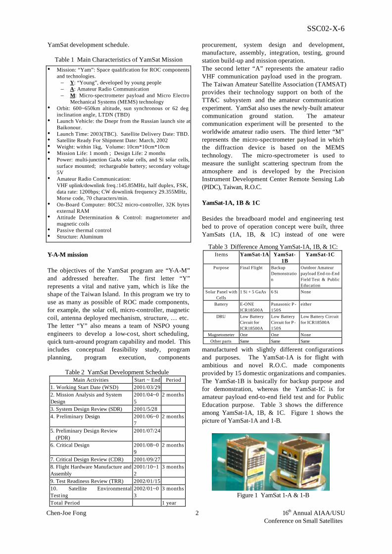
manufactured with slightly different configurations and purposes. The YamSat-1A is for flight with ambitious and novel R.O.C. made components provided by 15 domestic organizations and companies. The YamSat-1B is basically for backup purpose and for demonstration, whereas the YamSat-1C is for amateur payload end-to-end field test and for Public Education purpose. Table 3 shows the difference among YamSat-1A, 1B, & 1C. Figure 1 shows the picture of YamSat-1A and 1-B.
Table 1 Main Characteristics of YamSat Mission
• Mission: “Yam”: Space qualification for ROC components and technologies.
– Y: “Young”, developed by young people – A: Amateur Radio Communication – M: Micro-spectrometer payload and Micro Electro
Mechanical Systems (MEMS) technology • Orbit: 600~650km altitude, sun synchronous or 62 deg
inclination angle, LTDN (TBD) • Launch Vehicle: the Dnepr from the Russian launch site at
Baikonour. • Launch Time: 2003(TBC). Satellite Delivery Date: TBD. • Satellite Ready For Shipment Date: March, 2002 • Weight: within 1kg, Volume: 10cm*10cm*10cm • Mission Life: 1 month ; Design Life: 2 months • Power: multi-junction GaAs solar cells, and Si solar cells,
surface mounted; rechargeable battery; secondary voltage 5V
• Amateur Radio Communication: VHF uplink/downlink freq.:145.85MHz, half duplex, FSK, data rate: 1200bps; CW downlink frequency 29.355MHz, Morse code, 70 characters/min. • On-Board Computer: 80C52 micro-controller, 32K bytes
external RAM • Attitude Determination & Control: magnetometer and
magnetic coils • Passive thermal control • Structure: Aluminum
Table 2 YamSat Development Schedule Main Activities Start ~ End Period
1. Working Start Date (WSD) 2001/03/29 2. Mission Analysis and System Design
2001/04~05
2 months
3. System Design Review (SDR) 2001/5/28 4. Preliminary Design 2001/06~0
7 2 months
5. Preliminary Design Review (PDR)
2001/07/24
6. Critical Design 2001/08~09
2 months
7. Critical Design Review (CDR) 2001/09/27 8. Flight Hardware Manufacture and Assembly
2001/10~12
3 months
9. Test Readiness Review (TRR) 2002/01/15 10. Satellite Environmental Test ing
2002/01~03
3 months
Total Period 1 year
Table 3 Difference Among YamSat-1A, 1B, & 1C: Items YamSat-1A YamSat-
1B YamSat-1C
Purpose Final Flight Backup Demonstration
Outdoor Amateur payload End-to-End Field Test & Public Education
Solar Panel with Cells
1 Si + 5 GaAs 6 Si None
Battery E-ONE ICR18500A
Panasonic P -150S
either
DRU Low Battery Circuit for ICR18500A
Low Battery Circuit for P -150S
Low Battery Circuit for ICR18500A
Magnetometer One One None
Other parts Same Same Same
Figure 1 YamSat 1-A & 1-B

SSC02-X-6
Chen-Joe Fong 3 16th Annual AIAA/USUConference on Small Satellites
YAMSAT DESIGN & ANALYSIS
YamSat hardware configuration is shown in Figure 2. YamSat is controlled by an 80C52 micro-controller with the B-Dot attitude control mechanism and the amateur-band communications link. Its power subsystem consists of surface-mounted GaAs/Si solar cells and rechargeable batteries. The YamSat satellite is planned to be packed into a deployer device built by California Polytechnic State University, called "P-Pod". It can open its door and release its contents of pico-satellites like a pea pod into a low earth orbit. In a box with a size of only 10cm x 10cm x 10cm, YamSat contains a battery, a micro-spectrometer payload, a attitude control system with two magnetic coils and one magnetometer, and circuit boards for Telemetry Track and Command. The YamSat satellite are divided into eight subsystems – Payload, Structure, Command & Data Handling (C&DH), Tracking, Telemetry & Command (TT&C), Electrical Power, Attitude Determination and Control, Thermal Control and Flight Software. The design and analysis of each subsystem are described in the following sections. Payload - Micro-spectrometer The potential scientific capability of the micro-spectrometer is used to study the atmosphere condition from the unsual albedo value, e.g., volcanic
aerosol, by measuring the solar energy reflected from the Earth (Albedo); and to study the atmosphere elements by measuring the sunlight scattering spectrum from the atmosphere. Another goal of the micro-spectrometer is to demonstrate the engineering feasibility of using an optical system as a YamSat payload. The MEMS technology is used to meet the mass and power requirements. The functional block diagram of the micro-spectrometer is shown as Figure 3. All the electronic components and opto-mechanics parts are fitted onto one single 8cm x 8cm circuit board. A mini-aperture lens with F-number 2 is mounted on the +X axis panel to collect the light coming from +Z direction. For severe environment consideration, quartz made lens and optical fiber are selected. The collected light is guided to a CMOS detector through the diffraction device by a 30 cm optical fiber. The
102/122 Quartz-Quartz Fiber
CMOS Detector256 Pixels
MEMS DiffractionDevice
Pre -Amplifier
A/D
Single ChipMicro-Controller
BUS/Payload Interface
Power Line/ 5V
F#2Quartz Lens
Clock/Driving Line
8 Bits Serial Signal
Optical SubsystemElectronic Circuit
259 Bytes/1.172sec2400 bps
102/122 Quartz-Quartz Fiber
CMOS Detector256 Pixels
MEMS DiffractionDevice
Pre -Amplifier
A/D
Single ChipMicro-Controller
BUS/Payload Interface
Power Line/ 5V
F#2Quartz Lens
Clock/Driving Line
8 Bits Serial Signal
Optical SubsystemElectronic Circuit
259 Bytes/1.172sec2400 bps
Figure 3 Micro-Spectrometer Block Diagram
Figure 2 YamSat Hardware Configuration
+Y Panel •Battery •Magnetic Coil #2
-X Panel •Magnetometer •Magnetic Coil #1 •HF Antenna #2
-Z Panel •TT&C Board •VHF Antenna #2
+X Panel •Micro-Spectrometer •HF Antenna #1
-Y Panel •OBMU Board
+Z Panel •DRU Board •VHF Antenna #1
X
Y
Z

SSC02-X-6
Chen-Joe Fong 4 16th Annual AIAA/USUConference on Small Satellites
optical fiber is used as a light guider and the slit of spectrometer. The diffraction device is made by LIGA technology. The light is separated by the diffraction device and projected to a CMOS detector with 256 pixels. The detection spectrum range is within 380 nm - 780 nm. The spectrum resolution is 12 nm. The generation rate of science data is set to 259 bytes/1.172sec. The PIC16C76 is used as the controller. The science data
and status of health data are transmitted to the main on-board controller via UART interface at rate of 2400 bps. In order to convert digital signal corrected by micro-spectrometer into usable data, two kinds of spectral calibrations are performed and there are Spectral Register Calibration and Spectral Response Calibration. Figure 4 shows the calibration system set up. The purpose of Spectral Register Calibration is to allocate the CCD pixel into spectrum. Through
Spectral Response Calibration, the obtained gray level can be converted into irradiance. As for Spectral Responsible Calibration, the light source is first measured by a calibrated sensor, then under the same condition (current, temperature, etc.), the calibrated sensor is replaced by micro-spectrometer and perform the measurement again, see Figure 5 (a) and (b). Because the calibrated sensor and micro-spectrometer are different, a system transferring function need to be established to correlate the measurement data. Structure and Mechanism Subsystem (SMS ) The Structure and Mechanism Subsystem of the YamSat is designed, analyzed, and tested by NSPO SMS engineers, while the flight structure is contracted out and machined by the domestic manufacturer. The main requirements for SMS are defined according to YamSat size of 10cm X 10cm X 10cm. Total mass of the YamSat does not exceed 1 kg; Center of Gravity (CG) is located within 2 cm of the geometric center; and the actual location of the CG is known to within 10 mm accuracy. A kill switch (micro switch) is mounted to the exterior of the YamSat to turn off all power when the YamSat is compressed in the P-POD. The antenna deployment mechanism was designed and built by National Cheng Kung University. All YamSat structures are constructed with 7075 type aluminum in order to avoid thermal mismatching between the P-POD deployer and YamSat. All electrical components are mounted on the side panels. On the +Z panel, the center hole is for the lens of the
Figure 4 Spectral Calibration System Setup
Figure 5(a) Irradiance of Light Source measured by Calibrated Sensor
Figure 5(b) Irradiance of Light Source Calibrated by Micro-Spectrometer
(a)
(b) Figure 6 Finite Element Simulation Result
Monochromator
Standard DetectorLens
Fiber
MicroSpectrometer
……….
380 780
Response Cal.
Reg. Cal.
Broadband Light
Source
Monochromator
Standard DetectorLens
Fiber
MicroSpectrometer
……….
380 780
Response Cal.
Reg. Cal.
Broadband Light
Source
0.000E+00
5.000E-03
1.000E-02
1.500E-02
2.000E-02
2.500E-02
3.000E-02
3.500E-02
4.000E-02
4.500E-02
5.000E-02
380 420 460 500 540 580 620 660 700 740 780
Wavelength (nm)
Rad
ianc
e(W
/cm
^2/s
r)
1 5 10 25 50 100 150
200 250 300 350 400 450FL
0
20
40
60
80
100
120
140
160
180
200
380
404
428
452
476
500
524
548
572
596
620
644
668
692
716
740
764
Wavelength
Gra
y L
evel

SSC02-X-6
Chen-Joe Fong 5 16th Annual AIAA/USUConference on Small Satellites
micro-spectrometer. The other two holes are for flight jumpers and electrical test port. According to requirements of YamSat for quasi-static and dynamic loads, 3 load cases on the FEM of YamSat are applied. Load Case1: X=0, Y=15g, Z=15g; Load Case2: X=15g, Y=0, Z=15g; Load Case3: X=10.6g, Y=10.6, Z=15g. The finite element simulation analysis result is shown in Figure 6. The results for stress and dynamic analyses shows that all margin of safety are shown positive value and hence the design are acceptable. Command and Data Handling (C&DH) Subsystem Figure 7 shows the electrical block diagram of YamSat satellite. A domestic 80C52 micro-controller, Winbond’s W77IE58, is chosen as the main on-board controller. The device is originally designed for industrial grade and the operation temperature range is –40 oC to +85 oC. There is a 32k bytes internal flash ROM for the flight software. One 32K bytes SRAM chip, Winbond W24258, is used for the storage of the Status Of Health (SOH) data, science data and amateur communication message. Based on the radiation test, the CPU and RAM can endure 10 months radiation in this orbit. The W77IE58 provides two sets of serial ports: one is used for telecommand and telemetry interface with TT&C subsystem, and the other is used for science data path with the micro- spectrometer. The external power monitor and watchdog timer chip, MAX696, is used for safeguard purpose. There are three analog inputs from the 3-axis magnetometers, APL Model 113. There are two analog outputs for the magnetic coils to generate the magnetic torque. There are 5 bilevel commands to control the unit on/off and 8 bilevel telemetry to get the status of the units. There are 5 analog telemetry
channels for voltage, current, and temperature. There is one analog antenna deployment control to deploy two antennas, and one antenna deployed telemetry to avoid repeating deployment. Tracking, Telemetry & Command (TT&C) Subsystem The YamSat satellite provides telecommand / telemetry link margins of 6 dB at a BER of 1x10⁻⁶ and a data rate of 1200bps via FSK VHF band (145.85 MHz
)over 85% of a sphere centered at the Satellite. A RF
module in the YAESU VX-1R is used for the half duplex communication. The initialization, operation frequency setting, and receive/transmit switching are controlled by the flight software. The Satellite is designed to downlink science data, Status of Health (SOH) data and amateur communication message data via VHF downlink communications. The telemetry format follows AX.25 protocol and is compatible with the amateur ground stations. Two commercial omni pole antennas with -5 dBi gain for amateur radio communication are used. The antenna length is 7 cm for each. The transmitter output power is 0.5W and the receiver sensitivity is -140dBm. There is one CW transmitter to transmit SOH data and YamSat call sign via 29.355MHz. The CW antennas are loop antenna type and the total length are about 1/4 wave length. Electrical Power Subsystem (EPS) The EPS is designed to generate, store, regulate, and distribute the electrical energy necessary for the whole satellite. In addition, a deployment circuit is designed to deploy the antenna. The primary power of EPS is provided by five strings of TEC3i GaAs solar
Figure 7 YamSat Electrical Block Diagram
Micro-
Controller
80C52
D/A
Converter
OP
Amp.
Magnetic
Coil #1, #2
A/D
Converter
OP
Amp.
3-axis
Magneto-
meter
CW Generator
FSK
Modulator
FSK
DemodulatorReceiver
Transmitter
DiplexerCoupler
Micro-
Spectrometer
RAM
32KBytes
Solar Array
...
x 6Solar Array
...
x 6
DC/DC
Converter
Power
Distribution
Power
Monitor
& WDT
Temperature
Sensor
Current
Telemetry
Voltage
Telemetry
Bilevel
Output
Bilevel
Input
Fiber
Coupler
3.75V+5V, -5V
To Units
Rx
Rx
Bi
145.85MHz
145.85MHz
29.355MHz
BiCoupler
Battery
Micro-
Controller
80C52
D/A
Converter
OP
Amp.
Magnetic
Coil #1, #2
A/D
Converter
OP
Amp.
3-axis
Magneto-
meter
CW Generator
FSK
Modulator
FSK
DemodulatorReceiver
Transmitter
DiplexerCoupler
Micro-
Spectrometer
RAM
32KBytes
Solar Array
...
x 6Solar Array
...
x 6
DC/DC
Converter
Power
Distribution
Power
Monitor
& WDT
Temperature
Sensor
Current
Telemetry
Voltage
Telemetry
Bilevel
Output
Bilevel
Input
Fiber
Coupler
3.75V+5V, -5V
To Units
Rx
Rx
Bi
145.85MHz
145.85MHz
29.355MHz
BiCoupler
Battery
SSC02-X-6
Chen-Joe Fong 6 16th Annual AIAA/USUConference on Small Satellites
cells and one string of Si solar cells manufactured by a domestic vender, the Shihlin Electric & Engineering Corp for space proven. They are assembled and bounded space qualified, and the workmanship has been verified by inspection, adhesive test and electrical output test. Three ICR18500A rechargeable lithium-ion batteries manufactured by domestic vender, the E-One Moli Energy Corp are responsible for energy storage. Vacuum test of battery under status below 10-4 mbar for 7 hours has been applied that approves its qualification in space environment. A DC/DC converter is designed to transfer battery voltage level around 3.6V to 5V for use of other subsystems except the transmitter and receiver that utilize power directly from battery. An additional low battery voltage protection circuit is implemented for extending the battery life and protecting sensitive loads. In case of lower battery voltage than 3.17V, the protection circuit will also cut off the power supply to flight computer and automatically restart it after the battery is charged to 3.84V. The conversion efficiency is above 70% according to the loading and the output power can reach 4.13W to meet the maximum power requirement. EPS also provide power switching to loads by using solid state power switches for power distribution. Through the comprehensive performance test they have tested and meet the requirements. Five operation modes are designed for YamSat satellite and addressed as follows: (1) Launch Mode: During the launch, the battery and the solar arrays are disconnected from the satellite power bus by the kill switch. No power consumption during this mode. (2) Safe Mode: After separation, the battery and the solar arrays are connected to the satellite power bus. The On-Board Controller circuit (8052, RAM, AD/DA...), the CW Generator and the Receiver are powered ON. (3) Communication Mode: The transmitter is turned ON by uplink telecommand, then the SOH and science data are downlinked during 10 minutes contact time. After that, The transmitter is turned off by the period setting. (4) Imaging Mode: The Micro-Spectrometer is turned ON by uplink telecommand during the sun light. The duration is with 1 min. (5) Attitude Control Mode: The magnetometer and magnetic coils are turned ON by uplink telecommand
to stabilize the satellite. Flight Software Subsystem (FSW) The flight software development process follows waterfall approach iterative process through requirements definition, coding, testing, verification & validation (V&V). The overall flight software is considered as one CSCI which is divided into several CSCs such as mores code generation and transmission, b-dot attitude control algorithm, command reception and processing, AX.25 telemetry generation and transmission, anomaly detection and recovery…etc. The YamSat operation has some unique limitations due to hardware design architecture. For example, 1) command reception and telemetry transmission can’t activate simultaneously since T&C RF with half-duplex capability only; 2)
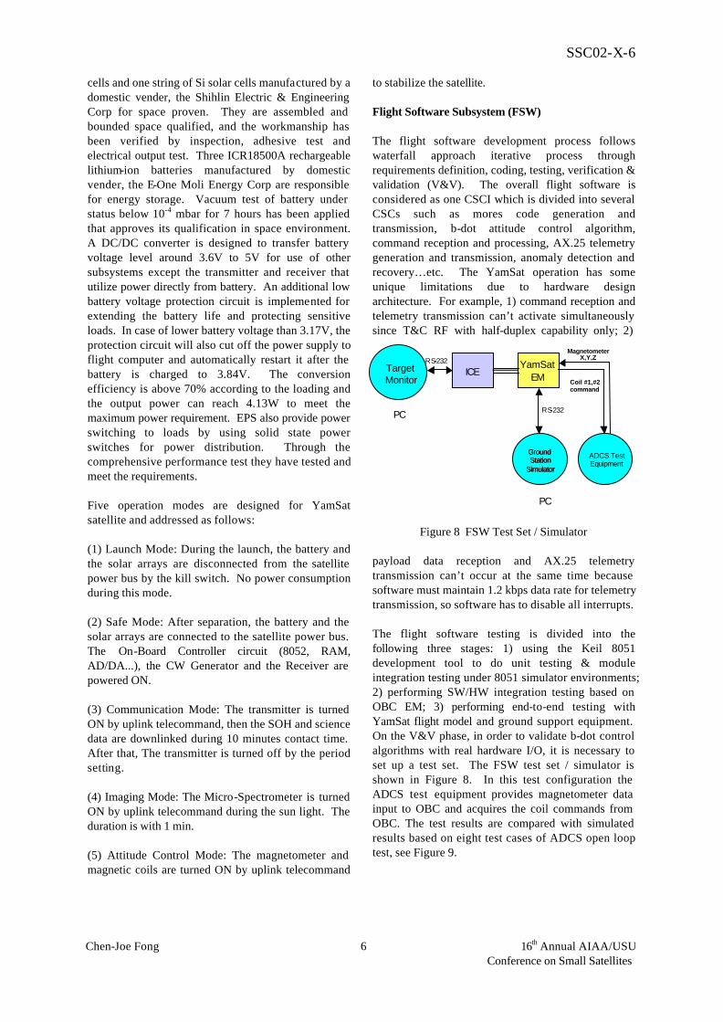
payload data reception and AX.25 telemetry transmission can’t occur at the same time because software must maintain 1.2 kbps data rate for telemetry transmission, so software has to disable all interrupts. The flight software testing is divided into the following three stages: 1) using the Keil 8051 development tool to do unit testing & module integration testing under 8051 simulator environments; 2) performing SW/HW integration testing based on OBC EM; 3) performing end-to-end testing with YamSat flight model and ground support equipment. On the V&V phase, in order to validate b-dot control algorithms with real hardware I/O, it is necessary to set up a test set. The FSW test set / simulator is shown in Figure 8. In this test configuration the ADCS test equipment provides magnetometer data input to OBC and acquires the coil commands from OBC. The test results are compared with simulated results based on eight test cases of ADCS open loop test, see Figure 9.
Figure 8 FSW Test Set / Simulator
ICE YamSat
EM
Ground Station
Simulator
RS - 232
Target Monitor
PC
PC
ADCS Test Equipment
Magnetometer X,Y,Z
Coil #1,#2 command
Ground Station
Simulator
-
RS - 232 -

SSC02-X-6
Chen-Joe Fong 7 16th Annual AIAA/USUConference on Small Satellites
Attitude Determination and Control Subsystem (ADCS) The attitude determination is performed via one 3-axis magnetometer while the attitude control is performed by 2 magnetic coils based on the B-dot control algorithm. Software simulator is used to simulate the dynamic response of ADCS. The design of the system is validated and modified before hardware implementation. The simulator composes of external disturbances, spacecraft bus, sensors, actuators and control system. The external disturbance sources include gravity-gradient torque, aerodynamic torque, solar-radiation torque and earth-magnetic torque. The gravity-gradient torque is very small for a typical CubeSat. The center of gravity offset is assumed to be 0.01 m for each axis , the atmospheric density is 6.0 x 10⁻¹⁴ kg/m3 at 650 km altitude; and the maximum value of the aerodynamic torque is 8.7 x 10⁻¹⁰ N-m. The solar radiation torque (Ts) is a product of force arm (rmp)
and solar-radiation Fs. The absorption and diffuse reflection coefficient are assumed to be 0.72 and 1.0 respectively. The maximum value of the solar radiation torque is 1.2 x 10⁻⁹ N-m. The residual magnetic dipole is assumed to be 0.001 Am2, the maximum value of the residual magnetic torque is 6.8x10⁻⁸ N-m for each axis. Moment of inertia are assumed to be Ixx = 0.00133, Iyy = 0.002, Izz = 0.00133 ,
Ixy = Iyz=Izx = 0, the magnetic moment of each X-axis
magnetic coil and Y-axis magnetic coil is 0.05Am2, the initial body rate is Vx=Vy=Vz=5 deg/sec. Figure 10 shows the simulation profile result of the YamSat rate. According to the simulation result the satellite will be steady in 120 minutes and rotates at two times the orbital rate at –Y axis. The ADCS open loop test are performed and the test result is consistent with the simulation result (see Figure 9), and therefore the result is adopted. Thermal Control Subsystem (TCS)3 The purpose of the satellite thermal control is to maintain each component within its specified
temperature range with required margins during all the mission phases. To reduce the power consumption, the thermal control is achieved through passive elements, such as insulation and surface finishes. The thermal analysis is based on the attitude control status that the negative Y-axis spin rate is 2 revolutions per orbit. The temperature requirements
for the key components are: (1) Battery: 0 to +45 °C for charge, -20 to +60 °C for discharge; (2) CPU: -40 to +85 °C; (3) Micro-Spectrometer: -20 to +40 °C; and (4) Magnetometer: -40 to +85 °C. A thermal isolator is introduced to connect the components to structure panels. (kscrew = 16.2 W/m-C, kisolator = 0.384 W/m-C). The capton tape is used on all internal surfaces of side panels. There is significant conduction heat loss from components to structure panels, and it may cause some unit temperatures, especially the battery, to become lower than their allowable temperature limits. The thermal isolators are designed for screws components to structure panels in order to avoid substantial conduction heat leak. The size of thermal isolator (including thickness t, and outer diameter D1) is studied in order to make battery worst cold case temperatures (Beta angle = 0 deg ) higher than its lower limit, i.e., 5 °C. More detailed design and analysis simulation result can be found in reference 3.
INTEGRATION AND TEST The YamSat Test Readiness Review (TRR) meeting was held on 15 January 2002. The primary objectives of this review is to update the satellite design result Figure 9 Test result and ADCS Open Loop Simulation
Result
-1
-0.8
-0.6
-0.4
-0.2
0
0.2
0.4
0.6
0.8
1
0 2000 4000 6000 8000 10000 12000 14000 16000 18000 20000time (sec)
S/C Y-axis projected on LVLH
XY
Z
-8
-6
-4
-2
0
2
4
6
8
0 2000 4000 6000 8000 10000 12000 14000 16000 18000 20000
time (sec)
S/C Rate : degree/S
Roll
Pitch
Yaw
Figure 10 Simulation Result of the YamSat Rate.
-2
- 1 . 5
-1
- 0 . 5
0
0 . 5
1
1 . 5
2
0 50 100 150 200 250 300
time (sec)
MAG Input Voltage
X
YZ
-3
-2
-1
0
1
2
3
0 50 100 150 200 250 300
time (sec)
MTQ Output Voltage
X
YZ
-2
-1.5
-1
-0.5
0
0.5
1
1.5
2
0 50 100 150 200 250 300
t ime (sec)
TEST CASE 6: MAG Output to YamSat
MAG X
MAG YMAG Z
-3
-2
-1
0
1
2
3
0 50 100 150 200 250 300
t ime (sec)
TEST CASE 6: MTQ Input from YamSat
MTQ X
MTQ Y
Simulation Result Test Result

SSC02-X-6
Chen-Joe Fong 8 16th Annual AIAA/USUConference on Small Satellites
since CDR; review the satellite flight units status; review the performance test result; review the environmental test plan and integration & test facility status; discuss the flight operation plan; and the most important, future development. Majority of YamSat integration and test activities are performed in NSPO’s I&T facility, e.g., comprehensive performance test (CPT), vibration test, thermal cycling, EMI/EMC test… etc. Due to the small size of the picosatellite, some test are performed by using other domestic test facilities, Table 4 shows the testing items and the testing facility provider information. Figure 11 shows the I&T schedule. Below we address some critical test activities. YamSat Thermal Cycling / Vacuum Test The thermal cycling and vacuum test are performed separately in order to simplify the rapid prototyping concept. The primary purpose of YamSat thermal cycling test is to provide a thermal environmental screening means to expose design, workmanship, material, and processing defects. In the test we have performed four hot and cold cycles for YamSat-1A satellite shown in Figure 12. The functional test is performed in the first and last cold and hot cycles to demonstrate all components are operation normally. The critical component for protoflight cold limit is
battery, where its temperature is -5°C, while for protoflight hot limit is spectrometer, where its temperature is 45°C.
Figure 12 YamSat Thermal Cycling Test
In order to control the YamSat thermal cycle test between the lower and upper limit temp erature of critical components, we performed a pretest to tune the thermal chamber setting temperature. From the pretest for YamSat-1B satellite test model, the tuning thermal chamber setting temperature is 40°C to let the critical component spectrometer reach its hot limit of 45°C while the cold end is -10°C to let the critical component battery to reach its cold limit of -5°C. The functional test was performed about 1.5 hours until the critical component reached its hot and cold limits for the first and last hot and cold cycles. From the four thermal cycles test for YamSat-1A satellite flight model as illustrated in Figure 12, the hot limit for thermal chamber setting temperature is 40°C while the measured critical component, spectrometer, reaches 44.8°C (within 2°C of spectrometer protoflight hot limit, 45°C). The cold limit for thermal chamber setting temperature is –10°C while the measured critical component, battery, reaches –6.2°C (within 2°C of battery protoflight cold limit, -5°C). According to the thermal cycle test results (see Figure 13), the YamSat-1A flight model can survive in these thermal conditions.
Figure 13 The YamSat Thermal Cycling Test Result
As to Thermal Vacuum Test, the YamSat satellite was put into a small vacuum chamber in PIDC and the
vacuum is kept at 5x10⁻⁷
mbar vacuum level and the test lasted for four hours. After the test
Figure 11 As-Run YamSat I&T Schedule
Table 4 Testing Item and Provider Test Item Test Facility Location/Figure Vibration Test
Small Shaker NSPO
Mass Property
Mass Property Measurement System
CSIST
Radiation Test
Radiation Test Facility
NTHU
End-to-End Test
Amateur Ground Station
NSPO & other amateur site
Thermal Vacuum Test
Small Thermal Vacuum Chamber Thermal Cycling Chamber
PIDC NSPO
EMI/EMC EMC Anechoic Chamber
NSPO
CPT Clean Room NSPO
Wait For Shipment
Satellite Test ReadinessReview
1/15
NSPO
YamSat 1AThermal Cycle
Test
2002/3/5,6
NSPO
YamSat 1A, 1BMass Property
Test
2002/3/7
CSIST
YamSat 1A, 1BVacuum Test
2002/3/12,13
PIDC
YamSat 1BThermal Cycle
Test
2002/1/23,24
NSPO
Battery Vacuum
Test
1/7
Leybold
YamSat 1C to Ground Station
End-to -End Test
2002/3/27
NSPO
YamSat-1A
VibrationTest
2002/3/4
NSPO
YamSat 1A, 1B
Baseline CPT
2002/3/4
NSPO
1 hrSoak
Function Test Return
To Ambient
Ambient
Battery Low Limit - 5 ℃
1 hr Soa
Spectrometer High Limit 45 ℃
Cold Function Test
Thermal Cycling
Hot Function Test
Cold Function Test
Hot Function Test
1 hr Soa
1 hr Soak
Function Test Ambient
Setting
1 hrSoak
Function Test
- 5 ℃
1 hr Soak
Spectrometer High Limit 45 ℃
Cold Function Test
Temperature Thermal
Cycling Hot Function Test
Cold Function Test
Hot Function Test
1 hr Soak
1 hr Soak
Function Test Settin
g

SSC02-X-6
Chen-Joe Fong 9 16th Annual AIAA/USUConference on Small Satellites
comprehensive performance test is performed to verify the YamSat’s function and performance. Figure 14 shows the thermal test picture.
Figure 14 YamSat Thermal Vacuum Test
Ground Systems to YamSat End-to-End Test The NSPO amateur ground station as shown in Figure 15 uses two YAGI antennas for VHF communication with 12dBi-antenna gain and 100W-transmitter power. The continuous wave (CW) circuit generates tracking beacon and SOH data under the control of the on-board controller. The CW frequency is 29.5MHz and the power output is 0.1W. Thanks to the technology support from Taiwan Amateur Satellite Association, this station can receive not only the YamSat telemetry during the End-to-End test but also the morse code signal sent from the amateur communication payload. The Call sign of the ground station is “BN0SPO” and the call sign of the YamSat is “BN01A”.
Figure 15 NSPO Amateur VHF & HF Ground Station
Antenna Pattern Test Antenna pattern test was performed in NSPO I&T EMC chamber (see Figure 16) and the result is used to prove the pattern coverage and the link budget. As the EMI/EMC test is not a necessary requirement in YamSat program, the EMI/EMC test is not performed. Owing to the launch delay, this test is planned to be performed in middle of July, 2002.
Figure 16 Antenna Pattern Test
Vibration Test The YamSat satellite vibration test was performed using NSPO 150 kN big shaker (See Figure 17), the rough test result shows that YamSat can sustain the launch requirement.
Figure 17 YamSat Vibration Test
Mass Property Test The YamSat satellite mass property test is performed using NSPO mass property measurement system (see Figure 18). The measured result shows the center of gravity is within the requirement and the weight is reduced during the manufacturing and is within 1 kg requirement.
ROC MADE COMPONENT The YamSat project aims to obtain space qualified satellite components constructed in Taiwan. In order to encourage and promote domestic companies to involve the development of space qualified components. The YamSat satellite provides a rapid prototyping opportunity to the vendor for space verification. YamSat-1A has the most ambitious and novel R.O.C. made components in this program, and is addressed below:

SSC02-X-6
Chen-Joe Fong 10 16th Annual AIAA/USUConference on Small Satellites
Figure 18 YamSat Mass Property Test
Solar Array Panel Shih-Lin electric & engineering Corp., one of our ROCSAT-1 space qualified ROC component vendors, was chosen to manufacture Silicon solar cell and assemble the YamSat solar panels (see Figure 19). The Si cell efficiency is tested with a result of 13% efficiency and was put into YamSat-1A & 1B. The high efficiency GaAs solar cells, were purchased from abroad to meet the design requirements.
Figure 19 Si Solar Array Panel
Magnetic Coils The ADCS group of NSPO made the needed two magnetic coils internally per the design requirement. From the test and calibration result shown, we have successfully built this components. (see Figure 20)
Figure 20 Magnetic Coils Micro-Controller and Static Read-Only Memory (SRAM) The required radiation total dose was analyzed and calculated using the SPENVIS software while the radiation test is performed using NTHU’s facility. (See Figure 21). The radiation test result shows that for a mission of 1 month, these ICs will survive per our test requirements of Total Dose of 1K Rad (Si) radiation test. The result also shows that the electronic devices, i.e., Micro-Controller and Static Read-Only Memory
(SRAM) in YamSat will receive a total dose of 15 kRad(Si) for the case of one year mission. For the case of micro-controller, the operation current, idle current (with VDD=3.0V), and operating voltage are within the specification. The idle current (with VDD=5.5V) is out of the specification. The power down current is a severe problem after radiation. Figure 22 shows the Micro-controller Radiation Test Result. The idle current of a micro-controller with VDD= 5.5 V operated at frequency of 12 MHz after various radiation total doses.
Figure 21 Radiation Test
0 5 10 15 20 25
10
15
20
25
30
35
40
spec.
VDD :5.5V , Fosc:12MHz
Dose rate : 2.6kRad/hr
Idle
Cu
rre
nt(
mA
)
Total dose(kRad)
chip1@ static chip2@ static
chip3@ in-operation chip4@ in-operation
chip3@ after annealing chip4@ after annealing
Figure 22 Micro-Controller Radiation Test Result
For the case of SRAM, the standby current is clearly immune to the space radiation. The operating power-supply current, loose function and access time are satisfactory after radiation at a low dose rate (See Figure 23). It seems too conservative to use the specification as criteria for radiation assurance; the circuit worst-case analysis to get a limit value of chip parameter for total dose assessment is more suitable. Printed Circuit Board (PCB) All the electronic PCBs were successfully layout, designed, manufactured & assembled in domestic company and the soldering technique was performed by the Acer Sertek Inc.

SSC02-X-6
Chen-Joe Fong 11 16th Annual AIAA/USUConference on Small Satellites
0 5 10 15 20 2530
40
50
60
70
80
90
100
110
120
130
Dose rate : 2.6kRad/hr
W24258
spec.@5V
chip3@in-operation
chip4@in-operation
chip3@after annealing
chip4@after annealing
I DD(m
A)
Total dose(kRad)
Figure 23 SRAM Radiation Test Result.
Flight Battery After the domestic built Lithium battery successfully went through vacuum test with vacuum at 1 x 10⁻⁴ torr and test period lasting for seven hours in January 2002 (See Figure 24), the performance of this component meets YamSat environmental test requirements. YamSat program therefore decided to use this in our YamSat design, and we also purchased NiCd battery for backup purpose.
Figure 24 Flight Battery Vacuum Test
Flight Structure Since the ROCSAT-2 flight structure was successfully designed, manufactured, and tested in Taiwan. All the YamSat flight structures of the SMS are also selected and tested in Taiwan. We had no problem to duplicate this task with younger engineers. Antenna Deployment Mechanism Base on the strict constraint of the space and weight budget, the YamSat’s antenna deployments
mechanism must be designed as simple as possible. the YamSat’s antennas are rigid short column in its geometric configuration, The hinge deployment concept was therefore selected and applied to the YamSat’s rigid short antenna pole. Through computer simulation and analysis , the antenna can deploy from 0o to 90o as anticipated. The deployments main components are made of Aluminum Alloy 7075T6. Finite element analysis (FEA) shows that the material is sufficient to sustain 15g launching acceleration and 150Hz vibration.
The lightweight 0.15 mm diameter nylon wire is selected to be YamSat antenna’s fixture device to fix the antenna in stowed position. When YamSat is released from P-POD and inject into the orbit , the current flows through the fusing wire and melt the nylon wire, that makes the fixing device disentangled, then the antennas deployed (see Figure 25).
LESSONS LEARNED4 Lessons learned during each major review meeting (SRR, PDR, CDR, TRR) are provided below as a summary of the overall YamSat program. Rapid-prototyping Models and Capabilities Build up Through various YamSat development phase NSPO has developed a rapid-prototyping, low-cost, short scheduling, quick turn-around program capability, including conceptual feasibility study, program planning, program execution, components procurement, system design, manufacturing, assembly, integration & testing, and ground station build-up. The experience can be shown as a template to the university and domestic industry. Currently two universities, NCU and NCKU have expressed their great interest to have NSPO to provide the YamSat technology transfer to them.
Figure 25 Antenna Deployment Mechanism
Z
Y
X
SSC02-X-6
Chen-Joe Fong 12 16th Annual AIAA/USUConference on Small Satellites
Improvement of YamSat Satellite Bus in the Future In order to become a standard bus for various payloads for remote sensing, communication, and science experiment… etc.. A modularized design for YamSat satellite bus is expected in the future. An upgrade of the current design to get more bus function and better bus performance is also foreseen. Owing to the specific limits for the picosatellite the thermal blanket and other active control method are not used in the current work; however, it is expectable that those approaches may manifest their potential in the near future due to the appearances of the MEMS technology. Also it is foreseen that through the MEMS technology application in the ADCS sensors and actuators, including micro-gyro, micro momentum wheel, micro-propulsion, micro sun sensor, micro earth sensor, micro star tracker, and micro GPS receiver, this picosatellite can achieve more 3-axis attitude control capability. More solar panel deployed mechanism can be added in and the use of state-of-the-art high efficiency solar cells can provide more power to the satellite and hence provide more advanced functions in the design. It is expected to use more advanced CPU, high capacity solid state memory, and high input/output channel number; and provide more complicated flight software in order to support more science data and versatile requirements from the payload. More communication subsystem capability is also expected to be improved in the future in order to provide more antenna gain, larger transmitting power, high performance RF transponder, high data downlink/uplink data rate, and more broadband communication channel. Technology Transfer to the academic to build different types of Picosatellite As a goal to disseminate the picosatellite technology to the university, NSPO is now cooperating with two national universities teams, i.e., NCKU and NCU, to build different types of picosatellites and nanosatellite bus for different mission. NSPO is also supporting the universities to open series of spacecraft design classes and teach the university students how to design a satellite from the beginning. Under the current cooperation plan, the university will lead the project and NSPO will provide the necessary technology learned from ROCSAT & YamSat programs Research and Development of Space MEMS / MNT Technology5 YamSat not only provides a space qualification test bed for local commercial components but also provides a new generation of MEMS space test bed. Due to the advent of MEMS space application in
recent years, the roadmap has been elaborated and studied in various space agencies. The short-term goal in NSPO is to follow the developed trending and roadmaps and to focus in the substitution of sensors and actuators. Micro- and Nano- technology development become nation’s initiative program, NSPO is the leader in the field of space application in Taiwan. Currently NSPO had contracted out 2 MEMS space application relevant project to the university, one is the development of micro-gyro and the other is the development of micro-GPS receiver. It is foreseen that more research projects on MEMS for space application will be contracted to the universities in the future. It is for sure some is expected to put on NSPO built or funded pico or nano-satellite for rapid prototyping and early in-orbit demonstrations. Long-Term Program NSPO’s goal to academia is to encourage the universities to engage in the more space science research and to participate in the satellite engineering design and development of pico / nano- satellite, high precision electro-optic sensors and other payloads. Through the success development of YamSat program, YamSat is widely exposed to the publicity and academia in Taiwan. YamSat has motivated many high school and university students to pursue their dream in the space science and engineering research and development. In the second phase 15 year long-term space program plan, NSPO emphasized the importance of development of pico / nano- satellite in the plan due to the successful experience in YamSat development. NSPO will provide funding to the innovated payload and satellite design concept through universities student competitions program. NSPO will provide the funding to the winner team to design and manufacture Picosatellite. NSPO will provide the launch support service, technology, and integration and test service. NSPO is increasing its annual mission oriented research budget next year in order to support more micro / nano / pico-satellite related research and development. A Path Finder toward Development of Nano-satellite Since NSPO has completed the YamSat of picosatellite class, and NSPO has gain precious experiences of small satellite design experiences in ROCSAT-1 program which the satellite weight is around 400 kg and ROCSAT-2 for 800 kg class, also NSPO has started the ROCSAT-3 program which is belong to a constellation design of 6 micro satellites whose weight is around 60 to 70 kg, the development of nanosatellite is become a obvious matter. Nanosatellite, which defined as satellite with weight from 1 kg to 10 kg, is one of NSPO’s next steps to develop this type of class satellite. NSPO will take YamSat program experience and technology transfer

SSC02-X-6
Chen-Joe Fong 13 16th Annual AIAA/USUConference on Small Satellites
model and apply to the development of nanosatellite. That is, NSPO and the domestic teams will build a nanosatellite by its own in the coming future. In NSPO’s second phase of 15-year space program starting from 2004, NSPO will make commitment of developing at least 5 to 10 pico- and/or nano-satellites in the next 15 year plan. Nano-satellite constellation and/or mother-daughter design concept is also planned and welcomed for innovated ideas
CONCLUSIONS YamSat has opened up an innovative avenue for conducting new academic, educational, and low-cost space research experimentation. Through the successful development of YamSat NSPO has made commitment of developing more than 5 to 10 pico- and/or nano-satellites in his second phase 15 year long-term space program plan. This YamSat experience gives us fruitful lessons the next picosatellite in Taiwan’s universities. Currently two universities, NCU and NCKU have addressed their great interest to join with NSPO to upgrade the YamSat current design. More studies on MEMS technologies for space application project are funded to university and is foreseen to increase in the future. YamSat program has become another major milestone after ROCSAT-1 program in the Nation’s space program. Acknowledgments The authors would like to thank NSC for its encouragement, with special thanks to NSC vice chairman , Dr. Ching-Jyh Shieh. The authors would also like to acknowledge NSPO upper management’s support, Dr. Lou-Chuang Lee. Professor J. N. Juang in the National Center for High-Performance Computing is also thanked for his lectures in the “Spacecraft System Design” class between January 17 and May 4, 2001 and the constantly encouragements on the YamSat program development. All the members of YamSat team on every aspect are acknowledged, to name only a few of the key members: SE: Y.-Y. Lee; SMS: C.-P. Chang; C&DH: Redman Lo, L.-K. Huang & J.- S. Wu; TT&C: T.-L. Ni & I-Y. Tarn; EPS: James Yeh; ADCS: Y.-W. Jan, C.-T. Lin; TCS: J.R. Tsai, L.-H. Hu & C.-S. Kang; and I&T: C.-C. Chin, Judan Chang, H.-M. Tseng, Sunny Lin, C.-F. Dai & Yow-Hua Chen. Many thanks to local industrial provider, especially Shihlin Electrical & Engineering Corp, E-One Moli Energy Co.; Taiwan Amateur Satellite Association (TAMSAT), especially BV2AC; Precision Instrument Development Center (PIDC); and Aerospace Science and Technology Research Center (ASTRC). References
1. Hank Heidt, Jordi Puig-Suari, Augustus S.
Moore,Shinichi Nakasuka, Robert J. Twiggs, “CubeSat: A new Generation of Picosatellite for Education and Industry Low-Cost Space Experimentation”, Proceedings of the 14th Annual AIAA/USU Conference on Small Satellites, Logan, Utah, USA, August 13-16, 2000.
2. Albert Lin, Chih-Li Chang, Steven Tsai , Chen-Joe
Fong, Chan-Peng Chang, Robin Lin, Chin Wen Liu, Marco Yeh, Men-Hsuang Chung, Hsu-Pin. Pan, & Chi-Hung Hwang, Yamsat: the First Picosatellite being Developed in Taiwan, SSC01-VIIIb-8, Proceedings of the 15th Annual AIAA/USU Conference on Small Satellites, Logan, Utah, USA, August 13-16, 2001.
3. Lee-Her Hu, Ming-Shong Chang, Meng-Hsuan
Chung, and Jih-Run Tsai, YamSat Thermal Control Design and Analysis , 2002 Annual CIROC/CSCA/AASRC Joint Conference, 23 March 2002.
4. NSPO Second Phase 15-year Long-Term Space
Technology Development Plan (Draft), 20 May 2002, NSPO.
5. The Third Round Table on Micro/Nano-
Technologies for Space, ESTEC, WPP_174, 15-17 May 2000.
Copyright © 2022 FDOKUMEN