Superior augmented reality registration by integrating landmark tracking and magnetic tracking
Landmark Pinnacle - Schueco
138
Virtual Construction Lab Design Proposal Landmark Pinnacle
-
Upload
khangminh22 -
Category
Documents
-
view
0 -
download
0
Transcript of Landmark Pinnacle - Schueco

Virtual Construction Lab
Design Proposal
LandmarkPinnacle


Executive Summary
Commercial Proposal
Design Proposal
Engineering Considerations
Installation Methodology
Air & Water Infiltration Performance
03
07
33
Organisational HistoryThe Schüco Business Model The Virtual Construction LabStrategic Partners
Typical Floor DiagramElevation & Overall PlanUnit Types & DetailsUnit 1 – Clear GlazedUnit 2 – Non-Vision PanelUnit 3 – Pop & Slide DoorUnit 4 – Alternate Clear GlazedGasket CompressionTypical Anchor DetailAnchor Installation Sequence
Structural PerformanceUnitised Frame WindowAnchor DesignThermal Performance
08122030
343638
74
100
73
121
127
Virtual Construction Lab of Schüco
Landmark Pinnacle – Table of Contents
1
Table of Contents


Executive Summary 3

Executive Summary
Schüco is an ideal partner for Landmark Pinnacle in providing innovative, top quality solutions for application on this high rise residential tower. Let us tell you why. To start with, we have a history of excellence in building façade technology dating back to the mid-twentieth century, and a long history of successfully completed façade programs on the most challenging of buildings. If you are unfamiliar with the storied history of Schüco, we invite you to peruse the Organisational History section starting on page 8.
More significantly, the documentation contained in the Organisational History section evidences Schüco’s ability to harness the power of design. Schüco façade systems are built on a bedrock of German engineering. The design quality of our systems catalog is well known, widely acknowledged, and easily recognized in our product detailing. This results from decades of highly technical façade systems development, resulting in a unique capability for system design – one of Schüco’s core strengths. We deliver this capability to key clients in a novel process that marries emergent design-assist façade delivery strategies with our classic system development practices, a process we call Accelerated Design-Assist Product Development (ADAPD). This service is delivered through the Virtual Construction Lab of Schüco (VCL). The VCL and ADAPD are discussed in detail in the Virtual Construction Lab section starting on page 20.
In order to successfully deliver the façade systems for the Landmark Pinnacle, we propose using the ADAPD process. The process puts the VCL team side-by-side with the Landmark Pinnacle design team, developing the
design while providing real-time feedback on such considerations as cost, schedule, constructability, and maintenance, while also creating an optimal deci-sion-making environment; every decision made with the full understanding of relevant impacts. The result will be a customized modification of a Schüco standard system, thereby combining the benefits of established perfor-mance with a novel appearance. We have gathered the information provided to us by the Landmark Pinnacle team, and proceeded with preliminary conceptual design to demonstrate capability and a possible approach. This work is captured in this proposal, and includes design, engineering, installation methodology, and air and water infiltration performance.
In addition to our leading-edge systems and product development capabilities, Schüco also boasts a unique product delivery strategy that has evolved over decades of endless refinements. Schüco delivers more than mere façade systems to your building project requirements – we deliver a comprehensive supply chain that spans the building process from concept design through fabrica-tion and installation, to lifecycle maintenance and, ultimately, renovation. The supply chain bears the Schüco stamp of approval in the form of a vendor/supplier certification program that qualifies the material supplier, fabricator, and/or installer as a Schüco supply chain partner. The supply chain services are discussed in detail in the Schüco Business Model section on page 12 of this volume.
Virtual Construction Lab of Schüco
Landmark Pinnacle – Executive Summary
4

The development process at Schüco does not end with the product design. Any customized modifications to a Schüco standard system as proposed herein are evaluat-ed in the context of the existing supply chain to assure that the customization will be seamlessly handled throughout the entire delivery process. This evaluation includes existing component supply lines, fabrication processes, machinery and equipment, material work-flows, installation procedures, QA assurance protocols, software tools, operation manuals, and training pro-grams required to fully support the system from design application through final installation, lifecycle mainte-nance, and renovation.
The façade system for the Landmark Pinnacle project will be no exception. We will work at the direction of the Landmark Pinnacle team in developing the system and then fine tune the supply chain to assure delivery through our network of suppliers, fabricators, and installers, enterprises that have been certified by Schüco in their role with respect to this specific project, in providing the following:
• System design including structural calculations
• Inventory, material storage, quality management and material handling practices
• Fabrication and assembly procedures
• Fabrication QA systems, procedures, and reporting requirements
• Installation and maintenance procedures
If this proposal is viewed favorable by Landmark Pinnacle, the proposed next step is to enter a contractual design development phase using a mutually acceptable derivation of the ADAPD process. Schüco proposes to contribute the following resources to the Landmark Pinnacle/Schüco development team:
Schüco Germany
• Executive Direction: Thomas Schlenker
• Project Manager: Ulf-Karsten Strack
Virtual Construction Lab of Schüco
• Strategic Oversight: Mic Patterson, LEED AP BD+C
• Principal Designer & Executive Manager: TJ DeGanyar Ph.D., PE
• Design Manager: Katie Gould
• Visualization Manager: Chris Chin
Few, if any, firms are so uniquely positioned to provide such a comprehensive and robust service offering, and we extend it only to a select few. It would be our great pleasure to build the façade systems for Landmark Pinnacle, and to build a productive and mutually rewarding ongoing client relationship in the process.
Virtual Construction Lab of Schüco
Landmark Pinnacle – Executive Summary
5


Commercial Proposal 7

Organisational History
1951 The birth of Schüco
Heinz Schürmann, a pioneer in the young Federal Republic of Germany, founds the company Heinz Schürmann & Co. in Porta Westfalica. In a small backyard with six employees, he produces shop windows, awnings and rolling grilles.
1954 A new home During the West German economic miracle, innovative windows and façades become more and more important. Schüco supplies them. The compa-ny is at the forefront of progress using light and modern aluminium. By moving to Bielefeld, Schüco finds a new home.
1955-1963 Crossing borders The rapid growth of Schüco requires new distribution channels. Commercial branches are established in Düsseldorf, Frankfurt, Stuttgart and Hamburg. License agreements and agency contracts enable new cooperation across Europe. In 1958, Schüco enters into a partnership with Alu König Stahl that still endures today.
1964 A strong connection that lasts to the present day The sale of Schüco to technology company Otto Fuchs KG opens up new business and technological horizons. Schüco founder Heinz Schürmann hands over management of the company to Dr.-Ing. Ernst von Wedel.
1964-1969 Ascending together Schüco presses ahead with expansion internationally. In 1964, subsidiaries are set up in France, the Netherlands and Denmark. Schüco Design is established in Borgholzhausen in the same year.
1970s A system-based approach
Schüco develops into a system supplier for alumini-um windows and doors. The company establishes new sites across Germany, continually expanding its sales network.
1970-1971 Ahead of the times Aluminium windows, doors and façades, as well as large sliding systems with outstanding thermal insulation: Two years before the oil crisis, Schüco is already focusing on climate protection and conserving resources with innovative products.
1972 The customer is king The topic of service becomes ever more important. Here too, Schüco is a pioneer. Schüco Service GmbH is founded as a fully owned subsidiary with three employees. The company provides software to help its metal fabrication customers with calculations and construction.
Schüco Milestones in Company History
Virtual Construction Lab of Schüco
Landmark Pinnacle – Commercial Proposal
8

Schüco Milestones in Company History
1980s A global player with new material
Schüco is also becoming increasingly international with licenses in Europe.
1980 Right on track Since the mid-1970s, the Schüco Express has been rolling through West Germany. Inside the carriages, customers can marvel at the latest window and façade technology – a unique form of product presentation.
1982 One step ahead Schüco has been meeting noise protection and environmental protection requirements successfully for years. Now the company also sets standards for fire security with the first approved fire protection system.
Market launch Schüco presents the new ISKOTHERM aluminium window system. The thermally insulated profiles are used for residential buildings and renovation projects in particular.
1990s A turning point
After the fall of the Berlin wall, building renovation with ecofriendly building materials in East Germany and Eastern Europe presents a major challenge. Schüco seizes this opportunity and expands its international business further. At the same time, the company enters the solar market and targets large commercial projects.
1990 An historic result Thanks to the construction boom in the east, Schüco turnover crosses the magical one billion D-mark threshold for the first time.
1992 Aiming high A new high-rise cassette warehouse in Bielefeld provides 22,000 storage areas across 81,000 m2.
Inexhaustible source of energy Schüco adds a third business division with solar thermal and photovoltaic products, taking responsibility for sustainable develop-ment.
Strong cooperation A combined steel company for Germany and Switzerland forms under the name Schüco Jansen Steel Systems.
Virtual Construction Lab of Schüco
Landmark Pinnacle – Commercial Proposal
9

2000s Growing together and conserving resources
Schüco identifies opportunities for globalization and extends its business into the USA, South America and China. With its divisions – Metal and Solar – the company is a specialist for the entire building envelope.
2005 Ultra-high performance The Schüco Technology Center is accredited as an independent and certified test institute for the building envelope.
Aluminium innovation The Schüco AWS / ADS window and door system sets new standards and replaces the renowned Royal S system.
2009 Temperature control Schüco presents the 2° Concept for the building envelope at BAU 2009. With pioneering, energy-efficient technology, the company makes an important contribution to restricting global warming to 2 degrees Celsius.
2011 Intelligent networking At BAU 2011, Schüco thrills visitors with the energy self-sufficient Schüco Energy3 Building. By networking windows, doors and façades, it produces more energy than it consumes.
2013 People. Nature. Technology. This is the Schüco slogan at BAU 2013. Four topic studios make the Schüco content interactive and an emotional experience. At the world’s leading exhibition for architecture, materials and systems in Munich, the company records 11,000 contacts – a record number of visitors.
A good investment A new production hall measuring 6,300 m2 is built in Weißenfels with 11 highly automated laminating lines for foiling and foil lamination of colored PVC-U profiles.
2014 Strong together The successful union between Otto Fuchs KG and Schüco International KG has now been in place for 50 years.
Technology you can touch The Schüco Showroom opens in Bielefeld, an interactive exhibition of metal construction products. Spread across 800 m², Schüco presents fascinating technologies and impressive systems using aluminium.
2015 Under the motto “Home. Work. Life” Schüco exhibited many innovative and stylish system solutions in Munich featuring ideal home, living and working environments. With approximately 13,000 registered guests Schüco set a new visitor record.
Virtual Construction Lab of Schüco
Landmark Pinnacle – Commercial Proposal
10

Historical Timeline
1951 Founded, Germany Heinz Schürmann founds Schüco and Company in Porta Westfalica, specialising in aluminium shop windows.
1960 Window System Launched
1970 National Expansion, Germany Founding of sites across Germany and development of the sales network. Schüco becomes a systems provider.
1980 European Expansion Internationalisation within Europe and entry into the PVC-U business.
1990 Global Distribution Worldwide expansion and entry into the solar business.
2003 United States Market Schüco is the specialist for sustainable solutions for the entire building envelope.
Virtual Construction Lab of Schüco
Landmark Pinnacle – Commercial Proposal
11

The Schüco Business Model
Market-Leading Building Façade Technology with a Focus on Supply Chain Management
Schüco combines best-in-market high-performance façade system products with a powerful design-to-site delivery strategy powered by a deep supply chain of multiple Schüco certified fabricators and installers.
Discerning Design Teams Choose Schüco
Schüco façade products are built on a bedrock of German engineering.
The standard-setting quality of Schüco systems is widely recognized, with design quality you can see. You don’t need a specification sheet, test report, or even a gage or measuring device; you can see it, easily, with your own eyes. Just look at the mitred-corner framing detail of a Schüco unitised window or curtainwall system, and try to find its equal in the marketplace.
We also make our unique façade product development capabilities available to clients and our supply chain partners. This includes a form of design-assist product development for both one-off project applications, or for the development of new systems exclusive to our client. These latter would include retail chains, for example, desirous of novel entry or lobby systems available as part of an exclusive brand. These services are discussed in detail in the following section on the Schüco Virtual Construction Lab (VCL).
Discerning Building Teams Choose Schüco
Many in the building industry are familiar with Schüco’s innovative high-performance façade systems. Most are less familiar with our equally innovative façade program delivery strategy, the process by which the requirements of the most demanding building façade programs are realized, with comprehensive services ranging from design through fabrication, assembly, installation, and even ongoing system maintenance if required. This
strategy involves a sophisticated international supply chain of fabrication/installation partners capable of providing you with virtually unlimited capacity, consis-tent quality, competitive pricing, and timely delivery, most often from local or regional providers.
As a global façade system supplier, Schüco has over 12,000 trained and prequalified fabrication/installation partners in 78 countries. Each supply chain partner is supported by a regional Schüco organization, all of which have full access to central services provided by the headquarters in Bielefeld, Germany. These services include:
• Pre-construction services; preliminary estimating, product consult
• Design-assist services; real time estimating, schedu-ling, constructability review (through the Virtual Construction Lab of Schüco, see following section)
• Product development
• Design-assist product development; development of exclusive systems for key clients through Virtual Construction Lab of Schüco (ADAPD process), see following section
• Material supply
• Warehousing
• Machinery design and supply
• Software development and support
• Testing and certification
• Fabrication training
• Installation training
Virtual Construction Lab of Schüco
Landmark Pinnacle – Commercial Proposal
12

Schüco leaves the fabrication and installation responsi-bilities to this highly trained network of service providers, which allows us to focus on further enabling this network with:
• Next-generation systems development and manage-ment practices
• Advanced digital fabrication processes, machinery, and know-how
• Intensive training programs
• A range of novel software tools to expedite fabrication, installation and management processes
We provide the fuel to our supply chain in the form of optimal product designs, digital fabrication processes, machinery to optimize workflows, and training programs that deliver know-how necessary to implement this advanced technology. A variety of special tools, punches, jigs and presses are made available to ensure optimal quality while reducing fabrication time. The proprietary software package SchüCal creates a digital platform that facilitates an efficient flow of data from design through fabrication. The machinery developed and provided to fabricators by Schüco can read and process the SchüCal data and drive fabrication processes, enabling file-to-fab-rication workflows at speed.
The attributes of our strategic supply chain are many, and are reviewed following.
Why Schüco: Standard or Customized Systems, Your Choice
As a system supplier with an unparalleled line of existing products, coupled with deep product development capabilities, Schüco can deliver a standard or customized façade program that can be supplied, fabricated, installed and serviced in 78 countries by prequalified and trained local and regional fabrication/installation part-ners. This strategy enables our clients to control the supply chain on their projects, optimizing cost, quality, lead time, and system solution.
Managing an Adaptive Delivery Process, Your Options
Upon development of a system design, we provide clients with two pathways to procurement:
• Contract directly with local Schüco partners for complete supply, fabrication, and installation services, or
• Contract directly with local Schüco partners for fabrication and installation services only. Procure product material kits directly from Schüco for delivery to the select Schüco partner.
For mission-critical facilities, or as desired to support delivery and emergency response times, a predetermined quantity of materials can be inventoried at strategically located Schüco or Schüco partner facilities international-ly to expedite installation, repair, or replacement.
Virtual Construction Lab of Schüco
Landmark Pinnacle – Commercial Proposal
13

Consistent Quality, Optimal Economy
Schüco has a long history of façade product development yielding a catalog of standardized systems unequaled in quality and performance. Moreover, we’ve developed a product delivery supply chain of extensively vetted and highly qualified fabrication and erection service providers. This international supply chain has successfully delivered thousands of challenging façade programs with consistent and predictable results as measured by schedule, quality, and economy. For its part, Schüco manages a stock of 44,000 pre-engineered components for delivery to its supply chain partners. These partners also benefit from the tools we provide them to seamlessly manage their processes from estimating through project close out, tools including our proprietary estimating and fabrication software, SchüCal.
This extensive, internationally distributed network of fabrication/installation partners provides significant advantages.
• Advantageous market labor rates can be leveraged.
• Multiple fabrication and installation service providers assure competitive pricing and delivery scheduling.
• Even the highest capacity product requirements can be met through the employment of multiple service providers.
• Travel and shipping costs can be minimized.
• Consistent top quality resulting from the intimate familiarity with system requirements by Schüco licensed fabrication/installation partners.
• Top level technical support provided to all licensed fabrication/installation partners by Schüco.
Virtual Construction Lab of Schüco
Landmark Pinnacle – Commercial Proposal
14

Design & Delivery Services
Schüco employs 2,500 engineers worldwide:
• developing and applying standard systems,
• providing customized solutions for bespoke building projects,
• and performing client-driven product development for key clients employing our novel ADAPD (Accelerated Design-Assist Product Development) process. (See the following Virtual Construction Lab section for more detail.)
In addition to the usual spectrum of design and engi-neering services, Schüco staff provide die drawings, technical support to fabrication/installation partners, develop tools, training programs, and assembly, fabrica-tion, and installation manuals for the application of all Schüco products.
An application design team is assigned to project applications, and typically includes the technical department of a Schüco facility of local country organiza-tion, the central design department at Schüco headquar-ters in Bielefeld, Germany, and the technical personnel of the select fabrication/installation partner(s).
The fabrication/installation partners typically carry the construction contract, servicing the Owner or General Contractor as required, while the local or regional Schüco office provides technical support. The technical groups at the Schüco regional facilities have deep familiarity with all of Schüco’s product catalog, and are also familiar with local codes and regulations pertaining to the building façade. The central technical department at headquarters in Germany reviews the work of the regional teams and interfaces with Schüco’s supply chain partners as required to ensure optimal design, constructability, scheduling, and economy.
Virtual Construction Lab of Schüco
Landmark Pinnacle – Commercial Proposal
15

Strategic Partners: Supply Chain Fabrication and Installation Service Providers and Certification
As a central element of the Schüco delivery strategy, we undertake the training and certification of qualified fabricators/installers to contract the supply, fabrication, installation and maintenance services required for the delivery of our products. The training includes:
• Designing with the systems, including structural calculations, code considerations, etc.
• Material storage, quality management, and material handling, plant organization and workflow
• Intensive hands-on fabrication, assembly, and installa-tion workshops
The qualification process also involves the review and approval of key vendor metrics including financial reports, QA/QC systems, facilities organization, machin-ery, reference projects, workforce skill and training, and health and safety planning.
Managing the Process
A delivery team is assigned for each Schüco project. The team makeup will vary as a function of project size, location, and the systems involved, but the core team is generally comprised of:
• Schüco project manager (from local/regional office)
• VCL team manager (if the Virtual Construction Lab is involved)
• Schüco HQ design manager
• Installation/fabrication manager(s) (certified Schüco service providers)
The fabrication/installation service providers carry full contractual responsibility for the provision of their services, and are solely responsible for the management and execution of their work. Schüco local/regional organizations in conjunction with Schüco headquarters support the fabrication and installation processes through the provision of materials and technical support.
Virtual Construction Lab of Schüco
Landmark Pinnacle – Commercial Proposal
16

Schüco InstallersFabricators
Architectural Advertising
LogisticsFabrication
Quality Assurance
Design Department
Bid SubmittalsMockups
Technical Support
Install LaborProject
Engineering
Training
Customer Service
Virtual Construction Lab of Schüco
Landmark Pinnacle – Commercial Proposal
17

Supply Chain Coordination
Schüco is flexible in working with clients and our supply chain partners. We will work with certified Schüco fabricators/installers to prepare a proposal in response to specific project requirements, either in a lead or support-ing role. Or we will nominate to the building team the certified service providers we think are most appropriate for the project, leaving the vendor qualification, design and procurement entirely to the building team and service providers. We can also provide coordination services from early on in the design process through the entire façade delivery process to final installation.
Procurement Planning
Each project provides a unique context. Schüco can manage the procurement of all materials and compo-nents required for a façade program, coordinating just-in-time delivery directly to select certified fabricators or to certified installers at the building site. Schüco manages the global inventory and warehousing of some 44,000 components in support of its products, minimizing lead time and greatly expediting the order-delivery process. Our deep supply chain comprised of multiple partners for all key components assures the fastest possible delivery regardless of project size.
Prefabricated Systems
All Schüco façade systems are based on prefabricated design strategies. Components come together at a certified Schüco fabricator on a just-in-time basis for assembly under qualified factory controlled conditions and under approved QA/QC procedures, with integrated reporting transparency. Prefabricated units are carefully packed and shipped to the building site ready for installation with minimal site work required.
Unit Assembly
As part of its façade product development practices, Schüco designs the machines and processes for product fabrication. The machines and know-how are then made available to our supply-chain partners. It is this digital fabrication technology that enables the quality product detailing, like mitred corner connections, at competitive pricing.
Virtual Construction Lab of Schüco
Landmark Pinnacle – Commercial Proposal
18

Quality Assurance
The QA and QC systems and practices of all certified fabricators/installers are subject to review as part of the certification process, with the prerequisite to certification that they meet demanding Schüco standards. These practices are well established with the catalog of Schüco products. New product development at Schüco includes the development of the systems and practices required to assure the determined standard of quality for that product. These systems and practices are then systemat-ically transferred to the fabricators and installers as part of the product technology transfer.
Just-in-time Delivery and Site Logistics
Schüco certified fabricators and installers are trained to coordinate just-in-time site deliveries as required to support site logistics and planning. Storage and staging areas are often limited, especially on dense urban building sites, and organization and coordination of deliv-eries can be vital in maintaining installation progress and minimizing impact to adjacent trades. In particularly demanding situations, offsite storage can be arranged to optimize material deliveries to site.
Visual and Performance Mockups
Schüco standard products have all been subject to some level of performance testing, but local requirements may vary. Schüco will coordinate with the select fabricator and installer service providers to accommodate both visual and performance mockup and testing programs.
Closeout Documents and Final Site Inspection
Schüco is available to review closeout documents and provide a final site inspection of installed products.
Ongoing Maintenance Services
In addition to fabrication and installation services, Schüco supply chain partners are also available to provide ongoing maintenance services as required for a given installation.
The following section explores the capabilities and services of the Virtual Construction Lab of Schüco (VCL).
Virtual Construction Lab of Schüco
Landmark Pinnacle – Commercial Proposal
19

The Virtual Construction Lab
The Virtual Construction Lab (VCL) is a powerful resource to Schüco clients. The Lab is based on a conceptual model that was initially developed to facilitate project delivery strategies structured to meet the challenges of novel and highly complex building façade projects. These strategies—often referenced under the umbrella term of design-as-sist—were highly collaborative, characteristically involving key design and delivery providers very early in the design process. Design-assist project delivery strategies quickly proved to be effective in delivering innovative solutions to complex building problems, while mitigating the risk that accompa-nies innovation in the building construction market. VCL is an adaptation of this model to the nuanced requirements of product development as opposed to the one-off nature of building design.
Virtual Construction Lab of Schüco
Landmark Pinnacle – Commercial Proposal
20

Product versus project
The Lab has developed a work process called Accelerat-ed Design-Assist Product Delivery or ADAPD. There are substantive differences between products and projects, and successful development processes are shaped by these differences; ADAPD is a process carefully attuned to the particular challenges of product development in the AEC (Architecture, Engineering, and Construction) industry. ADAPD is a strategic product development framework that transcends the limited boundary of product design to consider the full context of the product lifecycle from initial market research and concept development through post launch performance monitor-ing and evaluation. With a prospective client’s involve-ment, the ADAPD framework is customized to the specific requirements of each individual product develop-ment project.
VCL amplifies innovation in product development through the application of strategic design principles. While there are goals common to both product and project development, such as general considerations of economy, optimal product development demands special consideration of the following:
• Strategic product development that considers the full contextual environment of the product development life cycle.
• Product and production design to provide efficient fabrication and assembly at the projected scale of unit production.
• Product design for ease of installation across the range of applications.
• Robust supply chain development, matching projected program requirements with supply chain capacity, quality, inventory and delivery scheduling, geographic distribution, and installation, across the spectrum of site conditions.
Virtual Construction Lab of Schüco
Landmark Pinnacle – Commercial Proposal
21

Organization and Service Offerings
VCL is comprised of a small multi-disciplinary team of designers from disciplines ranging from architecture to product design, from building physics to parametric modeling. The concept embodied in VCL is unique in focusing on new product and technology development in the AEC market and has proven a powerful asset in developing niche product solutions as well as highly adaptive product technologies capable of wide variations in application. The ADAPD work process employed by the VCL includes a variety of strategies and techniques including sophisticated rapid visualization processes that speed conceptual design development, combined with progressive budgeting, scheduling, and constructability services that provide an optimized environment for early decision-making by a collaborative design team com-prised of representative stakeholders.
The Lab is structured as an independent business unit of Schüco acting as a specialty consultant to multiple clients, but is also capable of adopting a specialty team role while embedded within a partner organization. The Lab model, combined with the unique technical depth of the VCL team, is easily tuned to the specific require-ments of a wide variety of research and product develop-ment initiatives. The following are among the services offered by the VCL as part of a collaborative product development program.
Virtual Construction Lab of Schüco
Landmark Pinnacle – Commercial Proposal
22

Services
1. Product design
2. Value-engineering of new and value-analysis of existing products and systems
3. Parametric design
4. Complex geometry and geometric optimization
5. Rapid visualization: 3D modeling, rendering, animation, digital printing
6. Performance analysis: thermal, acoustical, structural, durability, environmental life cycle assessment and analysis, supported by various simulation and analytical techniques
7. Finite element and CFD modeling
8. Façade physics optimization: thermal, acoustical, moisture
9. Code checking
10. LEED, Energy Star, Green Globes, and other rating system facilitation
11. Rapid prototyping and visual mockup services
12. Digital fabrication and automation assistance
13. Manufacturing capacity analysis, production planning and monitoring
14. Constructability analysis, site operations planning and logistics
15. Maintenance programs, planning and training
16. Product commissioning through post-occupancy
17. Personnel training programs
18. Visual mockup construction and management
19. Performance mockup
20. Quality control program development and monitor-ing
21. Sales and presentation tools: proposal development, graphics, slideshows, animations, mockups
22. Product packaging design
23. Print and web promotional services
24. Event planning and production (conferences, workshops, etc.)
25. Branding, strategic planning, communication, infographics
Your project may require few or many of these capabili-ties. VCL will provide a proposal custom tailored to your project’s needs, drawn from the ADAPD framework.
Virtual Construction Lab of Schüco
Landmark Pinnacle – Commercial Proposal
23

Preplanning and the Basis of Design
VCL commences a product development project by working with the client to establish a clear set of goals and objectives for the product, which are documented in the Basis of Design (BOD). The BOD then becomes the reference for decision-making as the project moves forward, and its contents become the predominant criteria for evaluating progress. Ultimately, the success of the product will be determined by the extent to which the goals embedded in the BOD are met or exceeded. The BOD is a living document hosted by VCL but shared between VCL and the client, and subject to ongoing revision as the development process unfolds.
The BOD is finely tuned to the product development program, but generally includes definitions regarding the following:
• Market research and analysis requirements
• The standard of quality
• Scheduling milestones
• Market program: Budgets, price points, financial models, branding and identity, test marketing, promo-tion, sales
• Technical program: Performance requirements, engineering, analysis, production and facilities design, installation, service life, maintenance, supply chain development
• The user experience
• Program specific goals
• Testing and prototyping requirements
• Implementation: Plant and production, product management
• Environmental considerations: Green product certifica-tion, embodied energy profile, operational energy consumption, materials red list, recycling or reuse requirements
• Post-launch monitoring and evaluation
Virtual Construction Lab of Schüco
Landmark Pinnacle – Commercial Proposal
24

Designing the User Experience
The VCL team understands the importance of end-user considerations to guide the product development process. VCL works with the client and representative user groups as required to assure understanding of the user experience and the client’s goals for the user experience. This information can either be provided as an input to the VCL development process, or VCL can manage the acquisition and evaluation of this information. The user experience can be considered from pre-purchase market exposure through the use cycle and end-of-life disposal.
Design, Engineering, and Analysis: Implementing Innovative Building Technology
The core strength of VCL is a deep technical capability supporting creative problem-solving processes that consistently yield innovative solutions that are both practical and economical. Moreover, our work processes are purposefully designed to mitigate the risk associated with product innovations, yielding novel product solu-tions stripped of the risk and uncertainty that may accompany innovation in the challenging context of the built environment. Using a wide assortment of powerful tools, VCL in-house analytical capabilities include:
• Design development in various scales and materials
• Structural engineering
• Mechanical engineering
• Thermal and condensation analysis
• Acoustical analysis
• Kinetics and control systems
• Durability analysis
• Security assessment and analysis
The VCL works with a spectrum of design and analysis tools, including some self-developed software tools proprietary to Schüco that can be shared with clients as appropriate. Modeling tools such as Revit can be used by VCL to develop custom tailored BIM systems in support of new product developments. These models can be handed off to the client as part of the VCL service offering.
Virtual Construction Lab of Schüco
Landmark Pinnacle – Commercial Proposal
25

Rapid Multimedia Visualization
VCL’s design and technical capability is amplified by 3D visualization techniques embedded throughout the Lab’s digital workflows. These include 3D renderings in 2D media, including video animations, but quickly progress-es to full scale mockups and prototypes with the goal of getting into physical 3D as quickly as possible. Digital printing and other model-making techniques are a key output of the product development process. Video animations are often used to demonstrate function, supply chain design, and means-and-methods of assembly and installation.
Collaborative Digital Workflows
VCL work processes are steeped in collaboration. We stand shoulder-to-shoulder with our clients through the product development process, enabling decision-making by informing them in real time of the impacts of design decisions as they are made. Consequently, design progresses in the context of known impacts to the BOD, including such critical factors as cost, deployment, and maintenance.
Virtual Construction Lab of Schüco
Landmark Pinnacle – Commercial Proposal
26

Cost Management (CM), Value Engineering (VE), and Continuous Cost Modeling (CCM)
Cost is invariably a key metric in a product development program, and CM is the process by which that metric is controlled. A cost model is typically built for a VCL product development program and used as the basis for continuous budgeting throughout the design develop-ment process, thereby integrating cost management with ADAPD workflows. VE is also integrated into ADAPD as a means to optimize value outcomes as the design progresses. The process brings supply chain development forward and into design development by formally engaging key materials suppliers, vendors, fabricators, and specialty contractors to participate in the development of innovative and economical solutions that satisfy the product design intent.
Continuous cost modeling is a VCL management practice involving the definition of the basic elements and cost structure of the development program in detail. Budget targets along with VE opportunities are identi-fied, prioritized, scheduled and incorporated into the model. The cost model provides a real-time picture of the program budget as it evolves through design develop-ment and VE, thus facilitating accurate budget review throughout ADAPD process. The model helps to define areas where VE exercises may be most productive, and the results of the various VE exercises can easily be dropped into the cost model to evaluate impact.
Supply Chain Development
The engine of the ADAPD process is supply chain development. This begins with the involvement of key material and process providers early in design develop-ment, and continues right through to product launch, at which time the task of supply chain management can be handed off either to the client, or to Schüco as a value-added service. Supply chain development will drive the product delivery strategy, and must consider the entire product lifecycle from concept development through the operation and maintenance phase, and finally to end-of-life strategies of reuse, recycling, or disposal. The supply chain is critical to the development process, as it will ultimately play the dominant role in determining product quality, service life, lifecycle cost, the user experience, and environmental impacts.
Virtual Construction Lab of Schüco
Landmark Pinnacle – Commercial Proposal
27

Mockups and Prototypes
Mockups and prototypes play an integral role in the ADAPD process, varying in scale, material, and quality based on their role in the design development process. Sketch mockups may be relatively crude of cardboard; visual mockups are likely to be full scale and built from production materials. Digital printing is often used in the assembly of full-scale façade product mockups.
Testing
Façade systems and products typically require testing, and performance mockups are often constructed for this purpose. Whether actual production products or mockups are tested, VCL can develop and execute the testing program in conformance with specification and/or relevant code requirements. Durability testing is another common testing protocol. Tests can be sched-uled at a client’s facility, at the facility of an independent third-party certified testing laboratory, or at Schüco’s Technology Center in Bielefeld, Germany.
Virtual Construction Lab of Schüco
Landmark Pinnacle – Commercial Proposal
28

Durability Analysis, Maintenance Requirements and Lifecycle Planning
Lifecycle considerations of new product development begin early in the ADAPD process, starting with the definition of the design service life for the product in the BOD document. The new product or system is subject to durability analysis, and maintenance strategies are explored as a strategy to extend service life. This often involves testing in various forms as discussed above. Operable elements, for example, will be subject to repetitive cycling testing of a defined magnitude. Maintenance requirements can then be defined and published as part of the product offering. VCL can even develop personnel training programs to support opera-tions and maintenance procedures, including print and digital manuals, videos, webinars, and workshops. A program of value assessments of defined frequency during the operational phase of a product can monitor the effectiveness of maintenance practices and evaluate the approach of obsolescence.
Environmental Impacts and Sustainability Considerations
Sustainability considerations are gradually shifting from voluntary standards to codified requirements, while concerned enterprises are increasingly layering on their own program goals for environmental performance. Materials red lists are becoming more common. Resil-ience has become a predominant buzzword in the discussion of urban habitat. New product rating systems such as Green Globes and C2C have emerged with certification protocols. Environmental Product Declara-tions (EPDs) and their variant cousins are becoming a common requirement on building projects. VCL can evaluate a product and determine the most appropriate scheme and perform the required analysis or otherwise facilitate a program to achieve certification, or simply to assure a targeted level of environmental performance.
VCL as a Flexible and Adaptive Product Development Partner
Perhaps the most valuable components of the VCL– ADAPD equation is the flexibility of VCL team and the broad range of adaptability of the ADAPD process to the myriad nuances that comprise a product development program. It’s the technical depth and range of experi-ence of the VCL team that makes this possible. As a Schüco client, you may be able to bring the VCL onboard as part of your product development team. A specific proposal to accomplish just this — tuned to your program requirements — is either included in or accom-panies this document, or is otherwise available on request.
Virtual Construction Lab of Schüco
Landmark Pinnacle – Commercial Proposal
29

Strategic Partners
Strategic Fabrication Partners
Strategic fabrication partners for the Landmark Pinnacle project will meet the following requirements:
• Demonstrable experience fabricating Schüco systems.
• Possession of the machinery, equipment, and training to fabricate the system according to K drawings.
• Completion of a certification program specifically tailored to the Landmark Pinnacle project.
Virtual Construction Lab of Schüco
Landmark Pinnacle – Commercial Proposal
30

Certification Program
Fabrication partners will be required to attend and satisfactorily complete a training program in at the Schüco headquarters in Germany. Only select companies will be invited to participate. The program is intended to ensure that these fabrication partners can consistently meet the required standard of quality.
The fabrication partners will be trained in:
• Understanding shop drawings and the specifics of the system.
• Cutting and assembly of the profiles and fittings.
• QA/QC procedures for all fabrication processes.
• Packaging and crating for shipment.
Global partner network
Schüco’s global fabrication/installation partners number in the thousands, easily accommodating the global chain required for the project program. Our regional managers on every continent will be involved in the selection of qualified fabrication/installation partners in their local or regional territory.
Virtual Construction Lab of Schüco
Landmark Pinnacle – Commercial Proposal
31


Design Proposal 33

Typical Floor Diagram
This section outlines the proposal of the façade design for the Landmark Pinnacle in London, UK, through drawings, renders, and diagrams. The system imple-mented in this project is based on the standard Schüco UCC 65 SG (Unitised Customizable Construction), tailoring the aluminium-framed units into four distinct typologies to serve different needs of the architecture’s schema. UCC 65 SG is a structurally glazed system that provides a sleek, modern appearance with a relatively easy installation process and unparalleled quality control. The units designed for this project include a Clear Glazed model, a Non-Vision Panel, and a Pop and Slide Door double-width unit. An additional Alternate Clear unit helps integrate the Pop and Slide Door into the façade array but is otherwise identical to the Clear Glazed unit to help preserve a unified exterior design.
The units are anchored to the building structure at their base, with standard Schüco coupling gaskets creating an air-tight seal between adjacent units on all sides. The unit design incorporates a spandrel at the sill of each unit, covered with an opaque panel, and an HVAC vent at the top of each unit, which will connect into a larger system to be installed within the ceiling cavity. The HVAC vent is covered with a grill that when taken along-side the opaque panel of the spandrel above it, provides crisp latitudinal lines up the façade of the skyscraper.
The Clear Glazed unit provides floor-height views of the majestic Thames and surrounding Canary Wharf, while the Non-Vision Panel obscures interior shear and partition walls with an opaque shadowbox installed behind its double-pane glass. The Pop and Slide Door unit adapts the Schüco PASK Tilt/Slide from a standard entry system into a Juliet balcony by reimagining the standard form as a structurally glazed element, with a security balustrade installed behind it on the interior. As a unit, it is double the width of the units around it, a difference that has been tactfully minimized so that from the exterior one can scarcely tell it apart, maintain-ing the unity of the façade. Behind the Pop and Slide Doors is fitted a small winter garden, providing each apartment in the new high-rise a pleasant, refreshing oasis. The design of the Pop and Slide Door necessitates the Alternate Clear Glazed unit, which has an offset vertical aluminium profile to accommodate the dou-ble-width unit.
Taken together, the unified unitised façade proposed in this book lends the Landmark Pinnacle a bold face to match its audacious plan to become the tallest residen-tial tower in all of Europe. But no matter the size of the project, Schüco takes pride in furthering the science behind its façade systems, down to the smallest detail.
Virtual Construction Lab of Schüco
Landmark Pinnacle – Design Proposal
34

Clear Glazed Panel
Insulated Opaque Back Panel
Pop and Slide Doors
Glass Balustrade
Bottom Hung Projected in Opening
Virtual Construction Lab of Schüco
Landmark Pinnacle – Design Proposal
35

Elevation & Overall Plan
2950
2950
1235 1235 2470 1235
1235 1235 2470 1235
267
Virtual Construction Lab of Schüco
Landmark Pinnacle – Design Proposal
36


Units Types & Details
DH5
DV1
Unit 1Clear Glazed
Unit 2Non-Vision
Panel
Unit 3Pop and Slide
Door
Unit 4Alternate Clear
Glazed
DV1
DV3
DV3
DV2
DV2
DV4
DV4
DH1 DH4 DH2 DH3
Virtual Construction Lab of Schüco
Landmark Pinnacle – Design Proposal
38


Unit 1Clear Glazed
Virtual Construction Lab of Schüco
Landmark Pinnacle – Design Proposal
40

2950
400
175
DV1
Virtual Construction Lab of Schüco
Landmark Pinnacle – Design Proposal
41

Unit 1
38400
175
Legend
1. Vertical Aluminium Profile2. Horizontal Aluminium Profile3. Insulated Glass Unit4. Spandrel5. HVAC Vent
6. Vertical Coupling Gasket7. Horizontal Coupling Gasket8. Anchor9. Bracket10. Intermediate Aluminium Profile
11. Sliding Door Profile12. Insulated Non-Vision Panel13. Glass Balustrade14. Balustrade Bracket15. Steel Reinforcement
4
9
2
7
5
10
10
3
8
DV1
Virtual Construction Lab of Schüco
Landmark Pinnacle – Design Proposal
42

Virtual Construction Lab of Schüco
Landmark Pinnacle – Design Proposal
43

205
34
100
29
1
6
9
12
3
8
Legend
1. Vertical Aluminium Profile2. Horizontal Aluminium Profile3. Insulated Glass Unit4. Spandrel5. HVAC Vent
6. Vertical Coupling Gasket7. Horizontal Coupling Gasket8. Anchor9. Bracket10. Intermediate Aluminium Profile
11. Sliding Door Profile12. Insulated Non-Vision Panel13. Glass Balustrade14. Balustrade Bracket15. Steel Reinforcement
Unit 1DH1
Virtual Construction Lab of Schüco
Landmark Pinnacle – Design Proposal
44

Virtual Construction Lab of Schüco
Landmark Pinnacle – Design Proposal
45

Unit 2Non-Vision Panel
Virtual Construction Lab of Schüco
Landmark Pinnacle – Design Proposal
46

2950
400
175
DV2
Virtual Construction Lab of Schüco
Landmark Pinnacle – Design Proposal
47

Unit 2DV2
38400
175
4
9
2
7
12
5
10
10
3
8
Legend
1. Vertical Aluminium Profile2. Horizontal Aluminium Profile3. Insulated Glass Unit4. Spandrel5. HVAC Vent
6. Vertical Coupling Gasket7. Horizontal Coupling Gasket8. Anchor9. Bracket10. Intermediate Aluminium Profile
11. Sliding Door Profile12. Insulated Non-Vision Panel13. Glass Balustrade14. Balustrade Bracket15. Steel Reinforcement
Virtual Construction Lab of Schüco
Landmark Pinnacle – Design Proposal
48

Virtual Construction Lab of Schüco
Landmark Pinnacle – Design Proposal
49

Unit 2DH4
Legend
1. Vertical Aluminium Profile2. Horizontal Aluminium Profile3. Insulated Glass Unit4. Spandrel5. HVAC Vent
6. Vertical Coupling Gasket7. Horizontal Coupling Gasket8. Anchor9. Bracket10. Intermediate Aluminium Profile
11. Sliding Door Profile12. Insulated Non-Vision Panel13. Glass Balustrade14. Balustrade Bracket15. Steel Reinforcement
205
34
100
29
1
6
9
12
3
8
Virtual Construction Lab of Schüco
Landmark Pinnacle – Design Proposal
50

Virtual Construction Lab of Schüco
Landmark Pinnacle – Design Proposal
51

Unit 3Pop & Slide Door
Virtual Construction Lab of Schüco
Landmark Pinnacle – Design Proposal
52

As a vent, tilted open.
As a door, slid open.
Virtual Construction Lab of Schüco
Landmark Pinnacle – Design Proposal
53

Unit 3
2950
400
175
DV3
Pop and Slide Door
Virtual Construction Lab of Schüco
Landmark Pinnacle – Design Proposal
54

2950
400
175
1350
DV4
Virtual Construction Lab of Schüco
Landmark Pinnacle – Design Proposal
55

Unit 3DV3
Legend
1. Vertical Aluminium Profile2. Horizontal Aluminium Profile3. Insulated Glass Unit4. Spandrel5. HVAC Vent
6. Vertical Coupling Gasket7. Horizontal Coupling Gasket8. Anchor9. Bracket10. Intermediate Aluminium Profile
11. Sliding Door Profile12. Insulated Non-Vision Panel13. Glass Balustrade14. Balustrade Bracket15. Steel Reinforcement
38400
175
4
9
2
7
5
10
10
3
8
Virtual Construction Lab of Schüco
Landmark Pinnacle – Design Proposal
56

38400
175
Virtual Construction Lab of Schüco
Landmark Pinnacle – Design Proposal
57

Unit 3DV4
Legend
1. Vertical Aluminium Profile2. Horizontal Aluminium Profile3. Insulated Glass Unit4. Spandrel5. HVAC Vent
6. Vertical Coupling Gasket7. Horizontal Coupling Gasket8. Anchor9. Bracket10. Intermediate Aluminium Profile
11. Sliding Door Profile12. Insulated Non-Vision Panel13. Glass Balustrade14. Balustrade Bracket15. Steel Reinforcement
38400
175
11
11
49
14
2
7
5
10
10
3
8
13
Virtual Construction Lab of Schüco
Landmark Pinnacle – Design Proposal
58


Unit 4Alternate Clear Glazed
Virtual Construction Lab of Schüco
Landmark Pinnacle – Design Proposal
60

2950
400
175
DV1
Virtual Construction Lab of Schüco
Landmark Pinnacle – Design Proposal
61

Unit 4DH2
205
34
29
11
1015
3
13
Legend
1. Vertical Aluminium Profile2. Horizontal Aluminium Profile3. Insulated Glass Unit4. Spandrel5. HVAC Vent
6. Vertical Coupling Gasket7. Horizontal Coupling Gasket8. Anchor9. Bracket10. Intermediate Aluminium Profile
11. Sliding Door Profile12. Insulated Non-Vision Panel13. Glass Balustrade14. Balustrade Bracket15. Steel Reinforcement
Virtual Construction Lab of Schüco
Landmark Pinnacle – Design Proposal
62

Virtual Construction Lab of Schüco
Landmark Pinnacle – Design Proposal
63

Unit 4DH3
Legend
1. Vertical Aluminium Profile2. Horizontal Aluminium Profile3. Insulated Glass Unit4. Spandrel5. HVAC Vent
6. Vertical Coupling Gasket7. Horizontal Coupling Gasket8. Anchor9. Bracket10. Intermediate Aluminium Profile
11. Sliding Door Profile12. Insulated Non-Vision Panel13. Glass Balustrade14. Balustrade Bracket15. Steel Reinforcement
205
34
29 100
1
6
11
9
3
813
Virtual Construction Lab of Schüco
Landmark Pinnacle – Design Proposal
64

Virtual Construction Lab of Schüco
Landmark Pinnacle – Design Proposal
65

Gasket Compression
21 (X)
21 (x)
Virtual Construction Lab of Schüco
Landmark Pinnacle – Design Proposal
66

13 (x-8
)1
3
(x –
8)
Virtual Construction Lab of Schüco
Landmark Pinnacle – Design Proposal
67

Typical Anchor Detail
231
261
Legend
1. Vertical Aluminium Profile2. Horizontal Aluminium Profile3. Insulated Glass Unit4. Spandrel5. HVAC Vent
6. Vertical Coupling Gasket7. Horizontal Coupling Gasket8. Anchor9. Bracket10. Intermediate Aluminium Profile
11. Sliding Door Profile12. Insulated Non-Vision Panel13. Glass Balustrade14. Balustrade Bracket15. Steel Reinforcement
1
9
8
6
Virtual Construction Lab of Schüco
Landmark Pinnacle – Design Proposal
68


Anchor Installation Sequence
All anchors should be
installed and aligned
before unit installation
begins.
Install and assemble anchor into cast-in channel.
Align anchor to allow for structural tolerances.
Once positioning is confirmed drill and fix with tapered pin. As unit is lowered into anchor at base of unit temporary
fixings are used at the top.
Insert T-Bolts and rotate of 90°1
2
3 4
Virtual Construction Lab of Schüco
Landmark Pinnacle – Design Proposal
70

As the top of each unit is secured by the unit above the
temporary fixing below can be removed.
8
Next row of units are installed as per steps 4 - 6.
Temporary fixing removed
Once unit is secured by temporary fixing adjust unit height
with leveling screws at base anchor.
Only once an entire level of units are in place, then the
continuous horizontal gasket is installed.
5 6
7
Virtual Construction Lab of Schüco
Landmark Pinnacle – Design Proposal
71


Engineering Considerations 73

The system employed in this project is a customization of the standard Schüco UCC 65 SG unitised system. Schüco UCC 65 SG (Unitised Customized Construction) combines the high-quality look of a structural glazing façade with the standardized project processing of a high-performance and flexible modular system while providing individual design options.
The units are 2950mm tall with a typical width of 1235mm. The double width Pop and Slide Door unit have a width of 2470mm, seamlessly integrated into the array of the façade in a planar pattern. Each unit is divided into three main sections; A spandrel at the base, a floor-height vision panel in the middle, and an HVAC vent at the top of the unit. The Non-Vision Panel unit has an opaque shadow box in lieu of its vision panel (to hide interior shear and partition walls) and the Pop, and Slide Door unit has an intermediate vertical aluminium profile, which frames the operable door built into each unit. Each unit’s frame is composed of horizontal and vertical aluminium profiles, which are mitre cut at their corners and joined via corner cleats. Intermediate horizontal and vertical aluminium profiles are attached to this frame via screw raceways.
Unlike a standard UCC 65 SG construction, the units for this project are supported at the sill, interlocked to the unit above via a set of aluminium lifting logs (which are also used when installing the unit in place). Due to it
being a standing system, the units are fitted with temporary fixings at the head to keep them upright in anticipation of the next floor of units. Once they are inter-locked at the head, the temporary fixings are removed to be reused further up in the façade’s installation.
The self-weight is assumed to be carried by two bottom anchors, and the lateral loads are resisted by all four anchors (including those at the unit’s head). The anchors are shared by two adjacent units, and each anchor carries the total weight of two units. The anchors have a ± 36mm of tolerance moving left/right parallel to the edge of the slab, ± 12mm of tolerance moving in/out from the slab, and ± 16mm of tolerance moving up/down.
Wind loads are dictated by wind tunnel tests and load cases; combinations comply with ASCE 7-10 standards. Dead loads are computed based on individual compost weights. The lateral load transfer both through vertical spanning members to the attachment at anchors and connection logs.
The following sections present typical unit calculations for various components of the system, including framing, glass, hardware, and anchorage system. These calcula-tions are for typical unit dimensions and configurations. More detailed analysis and calculations will be required for the final design.
Structural Performance
Virtual Construction Lab of Schüco
Landmark Pinnacle – Engineering Considerations
74

Project: Landmark Date: 11.04.2016
Subject: Unitized frame window Page: 1 of 21
S2.1 Design Criteria
Sizes:
Maximum Glass Thickness: ≔Gt =34 mm 1.34 in
Safety Factors:
Tensile Rupture ≔Ωtrupture 1.95
Tensile Yielding ≔Ωtyield 1.65
Compression ≔Ωc 1.65
Flexure Rupture ≔Ωfrupture 1.95
Flexural Other ≔Ωfother 1.65
Shear Rupture ≔Ωsrupture 1.95
Shear Other ≔Ωsother 1.65
Tortion Rupture ≔Ωtorrupture 1.95
Tortion other ≔Ωtorother 1.65
Material Property ≔I 101
≔Alloy =F (( ,I 1)) 6005 ≔Temper =F (( ,I 2)) “T5” ≔E 10100 ksi
≔Ftu =⋅F (( ,I 6)) 1 ksi 38 ksi ≔Fty =⋅F (( ,I 7)) 1 ksi 35 ksi ≔Fcy =⋅F (( ,I 7)) 1 ksi 35 ksi
≔Ftuw =⋅F (( ,I 8)) 1 ksi 24 ksi ≔Ftyw =⋅F (( ,I 9)) 1 ksi 13 ksi ≔kt =F (( ,I 10)) 1.25
≔Fsu =⋅0.6 Ftu 22.8 ksi ≔Fsy =⋅0.6 Fty 21 ksi ≔G 3800 ksi
ProjectSubject
Date 11.07.2016
Virtual Construction Lab of Schüco
Landmark Pinnacle – Engineering Considerations
75
Landmark PinnacleStructural Performance

Project: Landmark Date: 11.04.2016
Subject: Unitized frame window Page: 2 of 21
S2.2 Computer Model
A computerized analytical model created in the software program SpaceGASS represents the structuralelements arranged according to the configuration in the following sketch. The section and material properties, deformation characteristics, and connectivity of the members are considered.
The left window (with DV1 as the following figure) is calculated due to its most critical section. The glass panel is pinned at the center of the structure as the grey plates in the following figure. The corner of the glass is constrained so that no rotation is allowed.
The unitized frame is modeled as aluminum beams, with the cross section described in section S2.3. The top horizontal beam of the glass panel employs section 1 while the bottom horizontal one for the glass panel uses section 2. The vertical member is made of the cross section 3 except member 7 and 4 which use section 4 to conncet the two windows. The section properties are extracted from the software program IES ShapeBuilder and assigned to the Finite Element Model in the SpaceGASS.
The dead load of the glass panel is added to the frame as point load at stiffner and the bottom of the frame, as well as the moment induced by the eccentricity of the glass panel. The wind load is extracted from the '1502419 RWDI-City Pride - Cladding Wind Load Study - Draft'. The 1.5 kPa wind pressure is considered for the glass panel as most positive wind load. while -1.75 kPa for the most negative wind load.
DH5
DV1
DV1
DV3
DV3
DV2
DV2
DV4
DV4
DH1 DH4 DH2 DH3
ProjectSubject
Date 11.07.2016
Virtual Construction Lab of Schüco
Landmark Pinnacle – Engineering Considerations
76
Landmark PinnacleStructural Performance

Project: Landmark Date: 11.04.2016
Subject: Unitized frame window Page: 2 of 21
S2.2 Computer Model
A computerized analytical model created in the software program SpaceGASS represents the structuralelements arranged according to the configuration in the following sketch. The section and material properties, deformation characteristics, and connectivity of the members are considered.
The left window (with DV1 as the following figure) is calculated due to its most critical section. The glass panel is pinned at the center of the structure as the grey plates in the following figure. The corner of the glass is constrained so that no rotation is allowed.
The unitized frame is modeled as aluminum beams, with the cross section described in section S2.3. The top horizontal beam of the glass panel employs section 1 while the bottom horizontal one for the glass panel uses section 2. The vertical member is made of the cross section 3 except member 7 and 4 which use section 4 to conncet the two windows. The section properties are extracted from the software program IES ShapeBuilder and assigned to the Finite Element Model in the SpaceGASS.
The dead load of the glass panel is added to the frame as point load at stiffner and the bottom of the frame, as well as the moment induced by the eccentricity of the glass panel. The wind load is extracted from the '1502419 RWDI-City Pride - Cladding Wind Load Study - Draft'. The 1.5 kPa wind pressure is considered for the glass panel as most positive wind load. while -1.75 kPa for the most negative wind load.
Project: Landmark Date: 11.04.2016
Subject: Unitized frame window Page: 3 of 21
S2.3 Section Properties
Section 1. The cross section of the top horizontal beam for the glass panel.
Section 2. The cross section of the top horizontal beam for the glass panel.
ProjectSubject
Date 11.07.2016
Virtual Construction Lab of Schüco
Landmark Pinnacle – Engineering Considerations
77
Landmark PinnacleStructural Performance

Project: Landmark Date: 11.04.2016
Subject: Unitized frame window Page: 4 of 21
Section 3. The cross section of the vertical beam.
Section 4. The cross section of the pinnacle beam (member 4 and member 7).
ProjectSubject
Date 11.07.2016
Virtual Construction Lab of Schüco
Landmark Pinnacle – Engineering Considerations
78
Landmark PinnacleStructural Performance

Project: Landmark Date: 11.04.2016
Subject: Unitized frame window Page: 4 of 21
Section 3. The cross section of the vertical beam.
Section 4. The cross section of the pinnacle beam (member 4 and member 7).
Project: Landmark Date: 11.04.2016
Subject: Unitized frame window Page: 5 of 21
S2.4 Load Cases and Combinations
S2.5 Reactions
ProjectSubject
Date 11.07.2016
Virtual Construction Lab of Schüco
Landmark Pinnacle – Engineering Considerations
79
Landmark PinnacleStructural Performance

Project: Landmark Date: 11.04.2016
Subject: Unitized frame window Page: 6 of 21
S2.6 Deflection Check
Load Case 101: 1.0 Dead Load + 1.0 Positive Wind Load on Glass Panel
Maximum deflection for horizontal beam
≔δy =0.0004 in ⎛⎝ ⋅3.333 10−5⎞⎠ ft
Member length
≔L =47.48 in 3.957 ft
Allowable deflection
≔δc =min⎛⎜⎝
,―――3.957
175―34
⎞⎟⎠
ft 0.023 ft
=<δy δc 1
Yes
Maximum deflection for vertical beam
≔δy =0.001 in ⎛⎝ ⋅8.333 10−5⎞⎠ ft
Member length
≔L =91.18 in 7.598 ft
Allowable deflection
≔δc =min⎛⎜⎝
,―――7.598
175―34
⎞⎟⎠
ft 0.043 ft
=<δy δc 1
Yes
Maximum deflection for pinnacle beam (member 4, 7)
≔δy =0.00001 in ⎛⎝ ⋅8.333 10−7⎞⎠ ft
Member length
≔L =15.748 in 1.312 ft
Allowable deflection
≔δc =min⎛⎜⎝
,―――1.312
175―34
⎞⎟⎠
ft 0.007 ft
=<δy δc 1
Yes
ProjectSubject
Date 11.07.2016
Virtual Construction Lab of Schüco
Landmark Pinnacle – Engineering Considerations
80
Landmark PinnacleStructural Performance

Project: Landmark Date: 11.04.2016
Subject: Unitized frame window Page: 6 of 21
S2.6 Deflection Check
Load Case 101: 1.0 Dead Load + 1.0 Positive Wind Load on Glass Panel
Maximum deflection for horizontal beam
≔δy =0.0004 in ⎛⎝ ⋅3.333 10−5⎞⎠ ft
Member length
≔L =47.48 in 3.957 ft
Allowable deflection
≔δc =min⎛⎜⎝
,―――3.957
175―34
⎞⎟⎠
ft 0.023 ft
=<δy δc 1
Yes
Maximum deflection for vertical beam
≔δy =0.001 in ⎛⎝ ⋅8.333 10−5⎞⎠ ft
Member length
≔L =91.18 in 7.598 ft
Allowable deflection
≔δc =min⎛⎜⎝
,―――7.598
175―34
⎞⎟⎠
ft 0.043 ft
=<δy δc 1
Yes
Maximum deflection for pinnacle beam (member 4, 7)
≔δy =0.00001 in ⎛⎝ ⋅8.333 10−7⎞⎠ ft
Member length
≔L =15.748 in 1.312 ft
Allowable deflection
≔δc =min⎛⎜⎝
,―――1.312
175―34
⎞⎟⎠
ft 0.007 ft
=<δy δc 1
Yes
Project: Landmark Date: 11.04.2016
Subject: Unitized frame window Page: 7 of 21
Load Case 102: 1.0 Dead Load + 1.0 Negative Wind Load on Glass Panel
Maximum deflection for horizontal beam
≔δy =0.0006 in ⎛⎝ ⋅5 10−5⎞⎠ ft
Member length
≔L =47.48 in 3.957 ft
Allowable deflection
≔δc =min⎛⎜⎝
,―――3.957
175―34
⎞⎟⎠
ft 0.023 ft
=<δy δc 1
Yes
Maximum deflection for vertical beam
≔δy =0.0013 in ⎛⎝ ⋅1.083 10−4⎞⎠ ft
Member length
≔L =91.18 in 7.598 ft
Allowable deflection
≔δc =min⎛⎜⎝
,―――7.598
175―34
⎞⎟⎠
ft 0.043 ft
=<δy δc 1
Yes
Maximum deflection for pinnacle beam (member 4, 7)
≔δy =0.00001 in ⎛⎝ ⋅8.333 10−7⎞⎠ ft
Member length
≔L =15.748 in 1.312 ft
Allowable deflection
≔δc =min⎛⎜⎝
,―――1.312
175―34
⎞⎟⎠
ft 0.007 ft
=<δy δc 1
Yes
ProjectSubject
Date 11.07.2016
Virtual Construction Lab of Schüco
Landmark Pinnacle – Engineering Considerations
81
Landmark PinnacleStructural Performance

Project: Landmark Date: 11.04.2016
Subject: Unitized frame window Page: 8 of 21
S2.7 The Top Horizontal Beam Check --- Member Number 2
Section Properties
≔As =S (( ,5 1)) in2 4.34 in2
≔d =S (( ,1 1)) in 8.818 in
≔Ixx =S (( ,6 1)) in4 35.52 in4
≔Iyy =S (( ,7 1)) in4 32.2 in4
≔Sxp =S (( ,11 1)) in3 7.83 in3
≔Syp =S (( ,13 1)) in3 6.325 in3
≔J =S (( ,48 1)) in4 20.24 in4
≔xs =S (( ,45 1)) in 3.217 in ≔Cw =S (( ,47 1)) in6 45.51 in6
≔Zx =S (( ,31 1)) in3 9.992 in3 ≔ys =S (( ,46 1)) in 2.372 in
≔βx =⋅S (( ,49 1)) in 1.467 in ≔Zy =S (( ,32 1)) in3 9.155 in3
≔ws =⋅As 170 pcf 5.124 ――lbf
ft≔rxx =
‾‾‾――Ixx
As
2.861 in
≔Syn =S (( ,14 1)) in3 10.2 in3 ≔ryy =‾‾‾――Iyy
As
2.724 in
≔Sxn =S (( ,12 1)) in3 8.295 in3
Member Forces
ProjectSubject
Date 11.07.2016
Virtual Construction Lab of Schüco
Landmark Pinnacle – Engineering Considerations
82
Landmark PinnacleStructural Performance

Project: Landmark Date: 11.04.2016
Subject: Unitized frame window Page: 8 of 21
S2.7 The Top Horizontal Beam Check --- Member Number 2
Section Properties
≔As =S (( ,5 1)) in2 4.34 in2
≔d =S (( ,1 1)) in 8.818 in
≔Ixx =S (( ,6 1)) in4 35.52 in4
≔Iyy =S (( ,7 1)) in4 32.2 in4
≔Sxp =S (( ,11 1)) in3 7.83 in3
≔Syp =S (( ,13 1)) in3 6.325 in3
≔J =S (( ,48 1)) in4 20.24 in4
≔xs =S (( ,45 1)) in 3.217 in ≔Cw =S (( ,47 1)) in6 45.51 in6
≔Zx =S (( ,31 1)) in3 9.992 in3 ≔ys =S (( ,46 1)) in 2.372 in
≔βx =⋅S (( ,49 1)) in 1.467 in ≔Zy =S (( ,32 1)) in3 9.155 in3
≔ws =⋅As 170 pcf 5.124 ――lbf
ft≔rxx =
‾‾‾――Ixx
As
2.861 in
≔Syn =S (( ,14 1)) in3 10.2 in3 ≔ryy =‾‾‾――Iyy
As
2.724 in
≔Sxn =S (( ,12 1)) in3 8.295 in3
Member Forces
Project: Landmark Date: 11.04.2016
Subject: Unitized frame window Page: 9 of 21
Check Compression
There is no axial force. The check for compression is satisfied.
Check Flexure
There is no moment in Y-Axis, so one only need to check the flexure in X-Axis
≔Mnx =min⎛⎜⎜⎝
,―――MnpYieldX
Ωfother
―――MnpRupX
Ωfrupture
⎞⎟⎟⎠
12.981 ⋅kip ft =――M1
Mnx
⋅3.852 10−4 =――M2
Mnx
⋅4.622 10−4
Check Shear
There is no shear in X-Axis, so one only need to check the flexure in Y-Axis
≔Type 0 1 stands for the support on both edges, while 0 stands for the support on one edge.
≔bs 8.25 in ≔ts 0.17 in ≔ds 8.82 in
The available shear strength is
≔VY =min⎛⎜⎜⎝
,―――Vnrup
Ωsrupture
―――Vnyield
Ωsother
⎞⎟⎟⎠
3.997 kip =――V1
VY
⋅7.505 10−4 =――V2
VY
0
=+⎛⎜⎜⎝――M1
Mnx
⎞⎟⎟⎠
2 ⎛⎜⎜⎝――V1
VY
⎞⎟⎟⎠
2
⋅7.116 10−7 =+⎛⎜⎜⎝――M2
Mnx
⎞⎟⎟⎠
2 ⎛⎜⎜⎝――V2
VY
⎞⎟⎟⎠
2
⋅2.136 10−7 OK
ProjectSubject
Date 11.07.2016
Virtual Construction Lab of Schüco
Landmark Pinnacle – Engineering Considerations
83
Landmark PinnacleStructural Performance

Project: Landmark Date: 11.04.2016
Subject: Unitized frame window Page: 10 of 21
S2.8 The Bottom Horizontal Beam - Member Number 15
Section Properties
≔As =S (( ,5 1)) in2 3.47 in2
≔d =S (( ,1 1)) in 5.904 in
≔Ixx =S (( ,6 1)) in4 14.99 in4
≔Iyy =S (( ,7 1)) in4 19.09 in4
≔Sxp =S (( ,11 1)) in3 6.616 in3
≔Syp =S (( ,13 1)) in3 3.442 in3
≔J =S (( ,48 1)) in4 1.863 in4
≔xs =S (( ,45 1)) in 1.614 in
≔ws =⋅As 170 pcf 4.097 ――lbf
ft≔Zx =S (( ,31 1)) in3 6.391 in3
≔rxx =‾‾‾――Ixx
As
2.078 in
≔βx =⋅S (( ,49 1)) in 1.093 in
≔ryy =‾‾‾――Iyy
As
2.346 in
≔Syn =S (( ,14 1)) in3 7.067 in3
≔Zy =S (( ,32 1)) in3 5.972 in3
≔Sxn =S (( ,12 1)) in3 4.12 in3 ≔ys =S (( ,46 1)) in 5.39 in
≔Cw =S (( ,47 1)) in6 11.87 in6
Member Forces
ProjectSubject
Date 11.07.2016
Virtual Construction Lab of Schüco
Landmark Pinnacle – Engineering Considerations
84
Landmark PinnacleStructural Performance

Project: Landmark Date: 11.04.2016
Subject: Unitized frame window Page: 10 of 21
S2.8 The Bottom Horizontal Beam - Member Number 15
Section Properties
≔As =S (( ,5 1)) in2 3.47 in2
≔d =S (( ,1 1)) in 5.904 in
≔Ixx =S (( ,6 1)) in4 14.99 in4
≔Iyy =S (( ,7 1)) in4 19.09 in4
≔Sxp =S (( ,11 1)) in3 6.616 in3
≔Syp =S (( ,13 1)) in3 3.442 in3
≔J =S (( ,48 1)) in4 1.863 in4
≔xs =S (( ,45 1)) in 1.614 in
≔ws =⋅As 170 pcf 4.097 ――lbf
ft≔Zx =S (( ,31 1)) in3 6.391 in3
≔rxx =‾‾‾――Ixx
As
2.078 in
≔βx =⋅S (( ,49 1)) in 1.093 in
≔ryy =‾‾‾――Iyy
As
2.346 in
≔Syn =S (( ,14 1)) in3 7.067 in3
≔Zy =S (( ,32 1)) in3 5.972 in3
≔Sxn =S (( ,12 1)) in3 4.12 in3 ≔ys =S (( ,46 1)) in 5.39 in
≔Cw =S (( ,47 1)) in6 11.87 in6
Member Forces
Project: Landmark Date: 11.04.2016
Subject: Unitized frame window Page: 11 of 21
Check Compression
Member Buckling
≔Lx 47.48 in ≔Ly Lx ≔Lz Lx
The member buckling strength =PncM 115.253 kip
Local Buckling
=FncL 33.551 ksi =PncL 119.455 kip
The member and local buckling interaction
≔PncI =⋅⋅⎛⎜⎜⎜⎝
――――⋅⋅0.85 π2 E
⎛⎜⎜⎝――binter
tinter
⎞⎟⎟⎠
2
⎞⎟⎟⎟⎠
―1
3
FeInter
―2
3 Ag 308.497 kip
The governing load is: ≔Pncgovern =min ⎛⎝ ,,PncI PncL PncM⎞⎠ 115.253 kip
The available compression strength is
≔Pnc =―――Pncgovern
Ωc
69.85 kip =――P1
Pnc
⋅7.158 10−5 OK
ProjectSubject
Date 11.07.2016
Virtual Construction Lab of Schüco
Landmark Pinnacle – Engineering Considerations
85
Landmark PinnacleStructural Performance

Project: Landmark Date: 11.04.2016
Subject: Unitized frame window Page: 12 of 21
Check Flexure
Check Yielding
≔MnpYieldX =min ⎛⎝ ,,⋅Zx Fcy ⋅⋅1.5 St Fty ⋅⋅1.5 Sc Fcy⎞⎠ 18.025 ⋅kip ft
≔MnpYieldY =min ⎛⎝ ,,⋅Zy Fcy ⋅⋅1.5 St Fty ⋅⋅1.5 Sc Fcy⎞⎠ 17.418 ⋅kip ft
Check Rupture
≔MnpRupX =⋅Zx ――Ftu
kt
16.191 ⋅kip ft ≔MnpRupY =⋅Zy ――Ftu
kt
15.129 ⋅kip ft
Check Local Buckling - Flexure
=Fb 47.352 ksi ≔Fc =FncL 33.551 ksi
≔Mnlbx =+⋅Fc ――If
ccf
⋅Fb ――Iw
ccw
62.471 ⋅kip ft
≔Mnlby =+⋅Fc ――If
ccf
⋅Fb ――Iw
ccw
5.951 ⋅kip ft
Check Lateral Torsional Buckling
X Axis (Strong Axis)
=MnmbX 15.882 ⋅kip ft
=k2 2.27
Y Axis (Weak Axis)
=MnmbY 15.216 ⋅kip ft
ProjectSubject
Date 11.07.2016
Virtual Construction Lab of Schüco
Landmark Pinnacle – Engineering Considerations
86
Landmark PinnacleStructural Performance

Project: Landmark Date: 11.04.2016
Subject: Unitized frame window Page: 12 of 21
Check Flexure
Check Yielding
≔MnpYieldX =min ⎛⎝ ,,⋅Zx Fcy ⋅⋅1.5 St Fty ⋅⋅1.5 Sc Fcy⎞⎠ 18.025 ⋅kip ft
≔MnpYieldY =min ⎛⎝ ,,⋅Zy Fcy ⋅⋅1.5 St Fty ⋅⋅1.5 Sc Fcy⎞⎠ 17.418 ⋅kip ft
Check Rupture
≔MnpRupX =⋅Zx ――Ftu
kt
16.191 ⋅kip ft ≔MnpRupY =⋅Zy ――Ftu
kt
15.129 ⋅kip ft
Check Local Buckling - Flexure
=Fb 47.352 ksi ≔Fc =FncL 33.551 ksi
≔Mnlbx =+⋅Fc ――If
ccf
⋅Fb ――Iw
ccw
62.471 ⋅kip ft
≔Mnlby =+⋅Fc ――If
ccf
⋅Fb ――Iw
ccw
5.951 ⋅kip ft
Check Lateral Torsional Buckling
X Axis (Strong Axis)
=MnmbX 15.882 ⋅kip ft
=k2 2.27
Y Axis (Weak Axis)
=MnmbY 15.216 ⋅kip ft
Project: Landmark Date: 11.04.2016
Subject: Unitized frame window Page: 13 of 21
≔Mnx =min⎛⎜⎜⎝
,,,―――MnpYieldX
Ωfother
―――MnpRupX
Ωfrupture
―――MnmbX
Ωfother
―――Mnlbx
Ωfother
⎞⎟⎟⎠
8.303 ⋅kip ft =――M1x
Mnx
0.001
OK
≔Mny =min⎛⎜⎜⎝
,,,―――MnpYieldY
Ωfother
―――MnpRupY
Ωfrupture
―――MnmbY
Ωfother
―――Mnlby
Ωfother
⎞⎟⎟⎠
3.607 ⋅kip ft =――M1y
Mny
0
Check Shear
Check the Y direction Shear
≔Type 0 1 stands for the support on both edges, while 0 stands for the support on one edge.
≔bs 1.5 in ≔ts 0.17 in ≔ds 8.0625 in
The available shear strength is
≔VY =min⎛⎜⎜⎝
,―――Vnrup
Ωsrupture
―――Vnyield
Ωsother
⎞⎟⎟⎠
3.245 kip =――V1y
VY
0 OK
Check the X direction Shear
≔Type 0 1 stands for the support on both edges, while 0 stands for the support on one edge.
≔bs 1 in ≔ts 0.125 in ≔ds 1.75 in
The available shear strength is
≔VX =min⎛⎜⎜⎝
,―――Vnrup
Ωsrupture
―――Vnyield
Ωsother
⎞⎟⎟⎠
1.591 kip =――V1x
VX
−0.123 OK
Check Torque
≔t 0.17 in
≔C =―Jt
10.959 in3 ≔Tnrupture =⋅――Fsu
kt
C 16.657 ⋅kip ft ≔Tnyield =⋅Fnyield C 19.178 ⋅kip ft
≔Tn =min⎛⎜⎜⎝
,―――Tnrupture
Ωtorrupture
―――Tnyield
Ωtorother
⎞⎟⎟⎠
8.542 ⋅kip ft
≔Safety =―T1
Tn
0
Check the Combination of Loads
=+++++――P1
Pnc
⎛⎜⎜⎝――M1x
Mnx
⎞⎟⎟⎠
2 ⎛⎜⎜⎝――M1y
Mny
⎞⎟⎟⎠
2 ⎛⎜⎜⎝――V1x
VX
⎞⎟⎟⎠
2 ⎛⎜⎜⎝――V1y
VY
⎞⎟⎟⎠
2 ⎛⎜⎜⎝―T1
Tn
⎞⎟⎟⎠
2
0.015 OK
ProjectSubject
Date 11.07.2016
Virtual Construction Lab of Schüco
Landmark Pinnacle – Engineering Considerations
87
Landmark PinnacleStructural Performance

Project: Landmark Date: 11.04.2016
Subject: Unitized frame window Page: 14 of 21
S2.10 The Vertical Mullions Check
Section Properties
≔As =S (( ,5 1)) in2 2.566 in2 ≔ws =⋅As 170 pcf 3.029 ――lbf
ft
≔d =S (( ,1 1)) in 8.071 in ≔βx =⋅S (( ,49 1)) in 0.283 in
≔Ixx =S (( ,6 1)) in4 19.23 in4 ≔rxx =‾‾‾――Ixx
As
2.738 in
≔Iyy =S (( ,7 1)) in4 0.737 in4 ≔ryy =‾‾‾――Iyy
As
0.536 in
≔Sxp =S (( ,11 1)) in3 4.597 in3 ≔Sxn =S (( ,12 1)) in3 4.597 in3
≔Syp =S (( ,13 1)) in3 4.597 in3 ≔Syn =S (( ,14 1)) in3 4.597 in3
≔J =S (( ,48 1)) in4 0.68 in4 ≔Cw =S (( ,47 1)) in6 5.455 in6
≔xs =S (( ,45 1)) in 1.854 in ≔ys =S (( ,46 1)) in 4.018 in
≔Zx =S (( ,31 1)) in3 6.22 in3 ≔Zy =S (( ,32 1)) in3 1.137 in3
Member Forces
ProjectSubject
Date 11.07.2016
Virtual Construction Lab of Schüco
Landmark Pinnacle – Engineering Considerations
88
Landmark PinnacleStructural Performance

Project: Landmark Date: 11.04.2016
Subject: Unitized frame window Page: 14 of 21
S2.10 The Vertical Mullions Check
Section Properties
≔As =S (( ,5 1)) in2 2.566 in2 ≔ws =⋅As 170 pcf 3.029 ――lbf
ft
≔d =S (( ,1 1)) in 8.071 in ≔βx =⋅S (( ,49 1)) in 0.283 in
≔Ixx =S (( ,6 1)) in4 19.23 in4 ≔rxx =‾‾‾――Ixx
As
2.738 in
≔Iyy =S (( ,7 1)) in4 0.737 in4 ≔ryy =‾‾‾――Iyy
As
0.536 in
≔Sxp =S (( ,11 1)) in3 4.597 in3 ≔Sxn =S (( ,12 1)) in3 4.597 in3
≔Syp =S (( ,13 1)) in3 4.597 in3 ≔Syn =S (( ,14 1)) in3 4.597 in3
≔J =S (( ,48 1)) in4 0.68 in4 ≔Cw =S (( ,47 1)) in6 5.455 in6
≔xs =S (( ,45 1)) in 1.854 in ≔ys =S (( ,46 1)) in 4.018 in
≔Zx =S (( ,31 1)) in3 6.22 in3 ≔Zy =S (( ,32 1)) in3 1.137 in3
Member Forces
Project: Landmark Date: 11.04.2016
Subject: Unitized frame window Page: 15 of 21
Check Compression
Member Buckling
≔Lx 91.81 in ≔Ly Lx ≔Lz Lx
The member buckling strength =PncM 7.406 kip
Local Buckling
=FncL 19.789 ksi =PncL 74.92 kip
The member and local buckling interaction
≔PncI =⋅⋅⎛⎜⎜⎜⎝
――――⋅⋅0.85 π2 E
⎛⎜⎜⎝――binter
tinter
⎞⎟⎟⎠
2
⎞⎟⎟⎟⎠
―1
3
FeInter
―2
3 Ag 55.424 kip
The governing load is: ≔Pncgovern =min ⎛⎝ ,,PncI PncL PncM⎞⎠ 7.406 kip
The available compression strength is
≔Pnc =―――Pncgovern
Ωc
4.489 kip =――P9
Pnc
⋅−6.683 10−4 OK
ProjectSubject
Date 11.07.2016
Virtual Construction Lab of Schüco
Landmark Pinnacle – Engineering Considerations
89
Landmark PinnacleStructural Performance

Project: Landmark Date: 11.04.2016
Subject: Unitized frame window Page: 16 of 21
Check Flexure
Check Yielding
≔MnpYieldX =min ⎛⎝ ,,⋅Zx Fcy ⋅⋅1.5 St Fty ⋅⋅1.5 Sc Fcy⎞⎠ 18.142 ⋅kip ft
≔MnpYieldY =min ⎛⎝ ,,⋅Zy Fcy ⋅⋅1.5 St Fty ⋅⋅1.5 Sc Fcy⎞⎠ 3.316 ⋅kip ft
Check Rupture
≔MnpRupX =⋅Zx ――Ftu
kt
15.757 ⋅kip ft ≔MnpRupY =⋅Zy ――Ftu
kt
2.88 ⋅kip ft
Check Local Buckling - Flexure
=Fb 45.91 ksi ≔Fc =FncL 19.789 ksi
≔Mnlbx =+⋅Fc ――If
ccf
⋅Fb ――Iw
ccw
60.523 ⋅kip ft
≔Mnlby =+⋅Fc ――If
ccf
⋅Fb ――Iw
ccw
5.767 ⋅kip ft
Check Lateral Torsional Buckling
X Axis (Strong Axis)
=MnmbX 10.338 ⋅kip ft
Y Axis (Weak Axis)
=MnmbY 5.41 ⋅kip ft
⎛MnpYieldX MnpRupX MnmbX Mnlbx⎞ M9
ProjectSubject
Date 11.07.2016
Virtual Construction Lab of Schüco
Landmark Pinnacle – Engineering Considerations
90
Landmark PinnacleStructural Performance

Project: Landmark Date: 11.04.2016
Subject: Unitized frame window Page: 16 of 21
Check Flexure
Check Yielding
≔MnpYieldX =min ⎛⎝ ,,⋅Zx Fcy ⋅⋅1.5 St Fty ⋅⋅1.5 Sc Fcy⎞⎠ 18.142 ⋅kip ft
≔MnpYieldY =min ⎛⎝ ,,⋅Zy Fcy ⋅⋅1.5 St Fty ⋅⋅1.5 Sc Fcy⎞⎠ 3.316 ⋅kip ft
Check Rupture
≔MnpRupX =⋅Zx ――Ftu
kt
15.757 ⋅kip ft ≔MnpRupY =⋅Zy ――Ftu
kt
2.88 ⋅kip ft
Check Local Buckling - Flexure
=Fb 45.91 ksi ≔Fc =FncL 19.789 ksi
≔Mnlbx =+⋅Fc ――If
ccf
⋅Fb ――Iw
ccw
60.523 ⋅kip ft
≔Mnlby =+⋅Fc ――If
ccf
⋅Fb ――Iw
ccw
5.767 ⋅kip ft
Check Lateral Torsional Buckling
X Axis (Strong Axis)
=MnmbX 10.338 ⋅kip ft
Y Axis (Weak Axis)
=MnmbY 5.41 ⋅kip ft
⎛MnpYieldX MnpRupX MnmbX Mnlbx⎞ M9
Project: Landmark Date: 11.04.2016
Subject: Unitized frame window Page: 17 of 21
≔Mnx =min⎛⎜⎜⎝
,,,―――MnpYieldX
Ωfother
―――MnpRupX
Ωfrupture
―――MnmbX
Ωfother
―――Mnlbx
Ωfother
⎞⎟⎟⎠
6.265 ⋅kip ft =――M9
Mnx
0.003 OK
≔Mny =min⎛⎜⎜⎝
,,,―――MnpYieldY
Ωfother
―――MnpRupY
Ωfrupture
―――MnmbY
Ωfother
―――Mnlby
Ωfother
⎞⎟⎟⎠
1.477 ⋅kip ft
Check Shear
Check the shear in Y-axis
≔Type 0 1 stands for the support on both edges, while 0 stands for the support on one edge.
≔bs 1.5 in ≔ts 0.17 in ≔ds 8.0625 in
The available shear strength is
≔VY =min⎛⎜⎜⎝
,―――Vnrup
Ωsrupture
―――Vnyield
Ωsother
⎞⎟⎟⎠
3.245 kip =――V9Y
VY
0
Check the shear in X-axis
≔Type 0 1 stands for the support on both edges, while 0 stands for the support on one edge.
≔bs 1 in ≔ts 0.125 in ≔ds 1.5 in
The available shear strength is
≔VX =min⎛⎜⎜⎝
,―――Vnrup
Ωsrupture
―――Vnyield
Ωsother
⎞⎟⎟⎠
1.591 kip =――V9X
VX
−0.038
Check the Combination of Loads
=+++――P9
Pnc
⎛⎜⎜⎝――M9
Mnx
⎞⎟⎟⎠
2 ⎛⎜⎜⎝――V9X
VX
⎞⎟⎟⎠
2 ⎛⎜⎜⎝――V9Y
VY
⎞⎟⎟⎠
2
⋅8.084 10−4 OK
ProjectSubject
Date 11.07.2016
Virtual Construction Lab of Schüco
Landmark Pinnacle – Engineering Considerations
91
Landmark PinnacleStructural Performance

Project: Landmark Date: 11.04.2016
Subject: Unitized frame window Page: 18 of 21
S2.10 The pinnacle (member 4, 7) Check
Section Properties
≔As =S (( ,5 1)) in2 2.093 in2
≔ryy =‾‾‾――Iyy
As
0.593 in
≔ws =⋅As 170 pcf 2.471 ――lbf
ft≔Sxn =S (( ,12 1)) in3 1.236 in3
≔d =S (( ,1 1)) in 3.543 in
≔Syn =S (( ,14 1)) in3 0.206 in3
≔Ixx =S (( ,6 1)) in4 2.189 in4
≔Cw =S (( ,47 1)) in6 0.057 in6
≔Iyy =S (( ,7 1)) in4 0.061 in4
≔ys =S (( ,46 1)) in ⎛⎝ ⋅2 10−4⎞⎠ in
≔rxx =‾‾‾――Ixx
As
1.023 in
≔Zy =S (( ,32 1)) in3 0.309 in3
≔Sxp =S (( ,11 1)) in3 1.236 in3
≔xs =S (( ,45 1)) in ⋅−2 10−4 in
≔Syp =S (( ,13 1)) in3 0.206 in3
≔Zx =S (( ,31 1)) in3 1.854 in3
≔J =S (( ,48 1)) in4 0.225 in4
≔βx =⋅S (( ,49 1)) in ⎛⎝ ⋅5 10−4⎞⎠ in
Member Forces
ProjectSubject
Date 11.07.2016
Virtual Construction Lab of Schüco
Landmark Pinnacle – Engineering Considerations
92
Landmark PinnacleStructural Performance

Project: Landmark Date: 11.04.2016
Subject: Unitized frame window Page: 18 of 21
S2.10 The pinnacle (member 4, 7) Check
Section Properties
≔As =S (( ,5 1)) in2 2.093 in2
≔ryy =‾‾‾――Iyy
As
0.593 in
≔ws =⋅As 170 pcf 2.471 ――lbf
ft≔Sxn =S (( ,12 1)) in3 1.236 in3
≔d =S (( ,1 1)) in 3.543 in
≔Syn =S (( ,14 1)) in3 0.206 in3
≔Ixx =S (( ,6 1)) in4 2.189 in4
≔Cw =S (( ,47 1)) in6 0.057 in6
≔Iyy =S (( ,7 1)) in4 0.061 in4
≔ys =S (( ,46 1)) in ⎛⎝ ⋅2 10−4⎞⎠ in
≔rxx =‾‾‾――Ixx
As
1.023 in
≔Zy =S (( ,32 1)) in3 0.309 in3
≔Sxp =S (( ,11 1)) in3 1.236 in3
≔xs =S (( ,45 1)) in ⋅−2 10−4 in
≔Syp =S (( ,13 1)) in3 0.206 in3
≔Zx =S (( ,31 1)) in3 1.854 in3
≔J =S (( ,48 1)) in4 0.225 in4
≔βx =⋅S (( ,49 1)) in ⎛⎝ ⋅5 10−4⎞⎠ in
Member Forces
Project: Landmark Date: 11.04.2016
Subject: Unitized frame window Page: 19 of 21
Check Compression
Member Buckling
≔Lx 11.811 in ≔Ly Lx ≔Lz Lx
The member buckling strength =PncM 71.668 kip
Local Buckling
=FncL 35 ksi =PncL 73.255 kip
The member and local buckling interaction
≔PncI =⋅⋅⎛⎜⎜⎜⎝
――――⋅⋅0.85 π2 E
⎛⎜⎜⎝――binter
tinter
⎞⎟⎟⎠
2
⎞⎟⎟⎟⎠
―1
3
FeInter
―2
3 Ag⎛⎝ ⋅3.034 103 ⎞⎠ kip
The governing load is: ≔Pncgovern =min ⎛⎝ ,,PncI PncL PncM⎞⎠ 71.668 kip
The available compression strength is
≔Pnc =―――Pncgovern
Ωc
43.435 kip
ProjectSubject
Date 11.07.2016
Virtual Construction Lab of Schüco
Landmark Pinnacle – Engineering Considerations
93
Landmark PinnacleStructural Performance

Project: Landmark Date: 11.04.2016
Subject: Unitized frame window Page: 20 of 21
Check Flexure
Check Yielding
≔MnpYieldX =min ⎛⎝ ,,⋅Zx Fcy ⋅⋅1.5 St Fty ⋅⋅1.5 Sc Fcy⎞⎠ 5.408 ⋅kip ft
≔MnpYieldY =min ⎛⎝ ,,⋅Zy Fcy ⋅⋅1.5 St Fty ⋅⋅1.5 Sc Fcy⎞⎠ 0.901 ⋅kip ft
Check Rupture
≔MnpRupX =⋅Zx ――Ftu
kt
4.697 ⋅kip ft ≔MnpRupY =⋅Zy ――Ftu
kt
0.783 ⋅kip ft
Check Local Buckling - Flexure
=Fb 52.5 ksi ≔Fc =FncL 35 ksi
≔Mnlbx =+⋅Fc ――If
ccf
⋅Fb ――Iw
ccw
24.712 ⋅kip ft
≔Mnlby =+⋅Fc ――If
ccf
⋅Fb ――Iw
ccw
14.273 ⋅kip ft
Check Lateral Torsional Buckling
X Axis (Strong Axis)
=MnmbX 4.255 ⋅kip ft
Y Axis (Weak Axis)
=MnmbY 0.869 ⋅kip ft
≔Mnx =min⎛⎜⎜⎝
,,,―――MnpYieldX
Ωfother
―――MnpRupX
Ωfrupture
―――MnmbX
Ωfother
―――Mnlbx
Ωfother
⎞⎟⎟⎠
2.409 ⋅kip ft
≔Mny =min⎛⎜⎜⎝
,,,―――MnpYieldY
Ωfother
―――MnpRupY
Ωfrupture
―――MnmbY
Ωfother
―――Mnlby
Ωfother
⎞⎟⎟⎠
0.401 ⋅kip ft
M101 M103
ProjectSubject
Date 11.07.2016
Virtual Construction Lab of Schüco
Landmark Pinnacle – Engineering Considerations
94
Landmark PinnacleStructural Performance

Project: Landmark Date: 11.04.2016
Subject: Unitized frame window Page: 20 of 21
Check Flexure
Check Yielding
≔MnpYieldX =min ⎛⎝ ,,⋅Zx Fcy ⋅⋅1.5 St Fty ⋅⋅1.5 Sc Fcy⎞⎠ 5.408 ⋅kip ft
≔MnpYieldY =min ⎛⎝ ,,⋅Zy Fcy ⋅⋅1.5 St Fty ⋅⋅1.5 Sc Fcy⎞⎠ 0.901 ⋅kip ft
Check Rupture
≔MnpRupX =⋅Zx ――Ftu
kt
4.697 ⋅kip ft ≔MnpRupY =⋅Zy ――Ftu
kt
0.783 ⋅kip ft
Check Local Buckling - Flexure
=Fb 52.5 ksi ≔Fc =FncL 35 ksi
≔Mnlbx =+⋅Fc ――If
ccf
⋅Fb ――Iw
ccw
24.712 ⋅kip ft
≔Mnlby =+⋅Fc ――If
ccf
⋅Fb ――Iw
ccw
14.273 ⋅kip ft
Check Lateral Torsional Buckling
X Axis (Strong Axis)
=MnmbX 4.255 ⋅kip ft
Y Axis (Weak Axis)
=MnmbY 0.869 ⋅kip ft
≔Mnx =min⎛⎜⎜⎝
,,,―――MnpYieldX
Ωfother
―――MnpRupX
Ωfrupture
―――MnmbX
Ωfother
―――Mnlbx
Ωfother
⎞⎟⎟⎠
2.409 ⋅kip ft
≔Mny =min⎛⎜⎜⎝
,,,―――MnpYieldY
Ωfother
―――MnpRupY
Ωfrupture
―――MnmbY
Ωfother
―――Mnlby
Ωfother
⎞⎟⎟⎠
0.401 ⋅kip ft
M101 M103
Project: Landmark Date: 11.04.2016
Subject: Unitized frame window Page: 21 of 21
=――M101
Mny
0.047 =――M103
Mny
0.055 OK
Check Shear
Check Shear in X direction
≔Type 0 1 stands for the support on both edges, while 0 stands for the support on one edge.
≔bs 3 in ≔ts 0.125 in ≔ds 8.0625 in
The available shear strength is
≔VX =⋅2 min⎛⎜⎜⎝
,―――Vnrup
Ωsrupture
―――Vnyield
Ωsother
⎞⎟⎟⎠
7.752 kip =――V101X
VX
0.018 =――V103X
VX
−0.021
Check Shear in Y direction
≔Type 0 1 stands for the support on both edges, while 0 stands for the support on one edge.
≔bs 8.0625 in ≔ts 0.125 in ≔ds 3 in
The available shear strength is
≔VX =⋅2 min⎛⎜⎜⎝
,―――Vnrup
Ωsrupture
―――Vnyield
Ωsother
⎞⎟⎟⎠
3.252 kip =――V101Y
VX
0 =――V103Y
VX
0
Check the Combination of Loads
=++⎛⎜⎜⎝――M101
Mny
⎞⎟⎟⎠
2 ⎛⎜⎜⎝――V101X
VX
⎞⎟⎟⎠
2 ⎛⎜⎜⎝――V101Y
VY
⎞⎟⎟⎠
2
0.004 OK
=++⎛⎜⎜⎝――M103
Mny
⎞⎟⎟⎠
2 ⎛⎜⎜⎝――V103X
VX
⎞⎟⎟⎠
2 ⎛⎜⎜⎝――V103Y
VY
⎞⎟⎟⎠
2
0.006 OK
ProjectSubject
Date 11.07.2016
Virtual Construction Lab of Schüco
Landmark Pinnacle – Engineering Considerations
95
Landmark PinnacleStructural Performance

S11 Anchor Design
Maximum Anchor Loads (From Reactions)
≔Px =2 ((0.165 kN)) 0.074 kip
≔Py =⋅2 ((0.012 kN)) 0.005 kip
≔Pyml =1000 lbf 1 kip
Material
Aluminum Extusions (6061-T5 or 6005A-T61)
≔Fbr =31 ksi 214 MPa ≔Fs =12 ksi 82.737 MPa
≔Fb =28 ksi 193.053 MPa ≔Ft =19 ksi 131 MPa
Minimum Wall Thickness ≔tm =0.125 in 3.175 mm
Bolts (Steel A325 or M5)
Diameter ≔db =.625 in 16 mm
Shear Capacity ≔Vbs =3.58 kip 15.925 kN
Bearing Capacity ≔Vbb =⋅⋅Fbr db tm 2.422 kip =Vbb 10.773 kN
ProjectSubject
Date 11.07.2016
Virtual Construction Lab of Schüco
Landmark Pinnacle – Engineering Considerations
96
Landmark PinnacleStructural Performance

S11 Anchor Design
Maximum Anchor Loads (From Reactions)
≔Px =2 ((0.165 kN)) 0.074 kip
≔Py =⋅2 ((0.012 kN)) 0.005 kip
≔Pyml =1000 lbf 1 kip
Material
Aluminum Extusions (6061-T5 or 6005A-T61)
≔Fbr =31 ksi 214 MPa ≔Fs =12 ksi 82.737 MPa
≔Fb =28 ksi 193.053 MPa ≔Ft =19 ksi 131 MPa
Minimum Wall Thickness ≔tm =0.125 in 3.175 mm
Bolts (Steel A325 or M5)
Diameter ≔db =.625 in 16 mm
Shear Capacity ≔Vbs =3.58 kip 15.925 kN
Bearing Capacity ≔Vbb =⋅⋅Fbr db tm 2.422 kip =Vbb 10.773 kN
Check the Anchor Bolt
Number of Bolts ≔N 2
Number of Row ≔Row 1
Eccentricities ≔Gx =78 mm 3.071 in
≔Gy =10 mm 0.394 in
Tolerance ≔Tx 1.5 in
≔Ty 2.0 in
Coordinates ≔Bx 0 in
≔By =60 mm 2.362 in
≔x
000−Bx
⎡⎢⎢⎢⎢⎣
⎤⎥⎥⎥⎥⎦
≔y
0By
By
0
⎡⎢⎢⎢⎢⎣
⎤⎥⎥⎥⎥⎦
Group Centroid ≔xc =――∑ x
N0 in
≔yc =――∑ y
N2.362 in
Applied Moment at Centroid of Bolts
≔Mdl.wl =+⋅Py⎛⎝ +−Gx xc Tx
⎞⎠ ⋅Px⎛⎝ ++Gy yc Ty
⎞⎠ 0.377 ⋅kip in
≔Mdl.ml =⋅⎛⎝ +Py Pyml⎞⎠ ⎛⎝ +−Gx xc Tx
⎞⎠ 4.596 ⋅kip in ≔Mdl =max ⎛⎝ ,Mdl.ml Mdl.wl⎞⎠ 4.596 ⋅kip in
Torsion Constant:
≔J =+∑⎛⎝ −y yc⎞⎠
2
∑⎛⎝ −x xc⎞⎠
2
11.16 in2
Resultant Shear Force at Each Fasterner:
≔V =
‾‾‾‾‾‾‾‾‾‾‾‾‾‾‾‾‾‾‾‾‾‾‾‾‾‾‾‾‾‾‾‾‾‾‾‾‾‾‾‾‾‾‾‾‾‾‾‾‾‾‾‾‾‾‾‾‾‾
+
⎛⎜⎜⎜⎝
+―Px
N―――――――――
⋅Mdl
‾‾‾‾‾‾‾‾‾‾‾‾‾‾‾‾+⎛⎝ −y yc
⎞⎠2
⎛⎝ −x xc⎞⎠
2
⋅J ‾‾2
⎞⎟⎟⎟⎠
2⎛⎜⎜⎜⎝
+―Py
N―――――――――
⋅Mdl
‾‾‾‾‾‾‾‾‾‾‾‾‾‾‾‾+⎛⎝ −y yc
⎞⎠2
⎛⎝ −x xc⎞⎠
2
⋅J ‾‾2
⎞⎟⎟⎟⎠
21
⋅3.7 10−2
⋅3.7 10−2
1
⎡⎢⎢⎢⎢⎣
⎤⎥⎥⎥⎥⎦
kip
≔Vmax =max ((V)) 1.001 kip
=―――――Vmax
min ⎛⎝ ,Vbs Vbb⎞⎠
0.413 < 1.0 OK
ProjectSubject
Date 11.07.2016
Virtual Construction Lab of Schüco
Landmark Pinnacle – Engineering Considerations
97
Landmark PinnacleStructural Performance

Check Anchor Hook
≔da =20 mm ⎛⎝ ⋅8 10−1⎞⎠ in ≔h =18 mm 0.709 in
≔th =.625 in 15.875 mm ≔aa =5 mm 0.197 in
Location A
Shear ≔fv =――Px
⋅th aa
0.603 ksi < =Fs 12 ksi OK
Tension ≔ft =――Py
⋅th aa
0.044 ksi < =Ft 19 ksi OK
Bending ≔fb =⋅―――⋅Px
⎛⎜⎝―da
2
⎞⎟⎠
⋅th aa2
6 7.236 ksi < =Ft 19 ksi OK
Combined =+⎛⎜⎜⎝―fb
Fb
⎞⎟⎟⎠
2 ⎛⎜⎜⎝―fv
Fs
⎞⎟⎟⎠
2
0.069 < 1.0 OK
Point B
Shear ≔fv =――Py
⋅th h0.012 ksi < =Fs 12 ksi OK
Tension ≔ft =――Px
⋅th h0.167 ksi < =Ft 19 ksi OK
Bending ≔fb =⋅―――――⋅Px
⎛⎜⎝
+―h2
―da
2
⎞⎟⎠
⋅th h26 1.1 < =Ft 19 ksi OK
Combined =+⎛⎜⎜⎝―fb
Fb
⎞⎟⎟⎠
2 ⎛⎜⎜⎝―fv
Fs
⎞⎟⎟⎠
2
0.001 < 1.0 OK
=+―ft
Ft
―fb
Fb
0.047 < 1.0 OK
Miantenance Load
Shear ≔fv =―――+Py Pyml
⋅th h2.27 ksi < =Fs 12 ksi OK
ProjectSubject
Date 11.07.2016
Virtual Construction Lab of Schüco
Landmark Pinnacle – Engineering Considerations
98
Landmark PinnacleStructural Performance

Check Anchor Hook
≔da =20 mm ⎛⎝ ⋅8 10−1⎞⎠ in ≔h =18 mm 0.709 in
≔th =.625 in 15.875 mm ≔aa =5 mm 0.197 in
Location A
Shear ≔fv =――Px
⋅th aa
0.603 ksi < =Fs 12 ksi OK
Tension ≔ft =――Py
⋅th aa
0.044 ksi < =Ft 19 ksi OK
Bending ≔fb =⋅―――⋅Px
⎛⎜⎝―da
2
⎞⎟⎠
⋅th aa2
6 7.236 ksi < =Ft 19 ksi OK
Combined =+⎛⎜⎜⎝―fb
Fb
⎞⎟⎟⎠
2 ⎛⎜⎜⎝―fv
Fs
⎞⎟⎟⎠
2
0.069 < 1.0 OK
Point B
Shear ≔fv =――Py
⋅th h0.012 ksi < =Fs 12 ksi OK
Tension ≔ft =――Px
⋅th h0.167 ksi < =Ft 19 ksi OK
Bending ≔fb =⋅―――――⋅Px
⎛⎜⎝
+―h2
―da
2
⎞⎟⎠
⋅th h26 1.1 < =Ft 19 ksi OK
Combined =+⎛⎜⎜⎝―fb
Fb
⎞⎟⎟⎠
2 ⎛⎜⎜⎝―fv
Fs
⎞⎟⎟⎠
2
0.001 < 1.0 OK
=+―ft
Ft
―fb
Fb
0.047 < 1.0 OK
Miantenance Load
Shear ≔fv =―――+Py Pyml
⋅th h2.27 ksi < =Fs 12 ksi OK
Check Anchor
≔wa =92 mm 3.622 in ≔ta =12 mm 0.472 in
≔dx =20 mm 0.8 in ≔dy =82 mm 3.2 in ≔TOLx =0.5 in 12.7 mm
Shear ≔fv =―――Py
⋅ta wa
⎛⎝ ⋅3.2 10−3⎞⎠ ksi < =Fs 12 ksi OK
Bending ≔fb =⋅―――――――――+⋅Px dy ⋅Py
⎛⎝ +dx TOLx⎞⎠
⋅⎛⎝ −wa ⋅2 ((1.0625 in))⎞⎠ ta2
6 4.4 ksi < =Fb 28 ksi OK
Combined =+⎛⎜⎜⎝―fb
Fb
⎞⎟⎟⎠
2 ⎛⎜⎜⎝―fv
Fs
⎞⎟⎟⎠
2
⋅2.5 10−2 < 1.0 OK
Miantenance Load
Shear ≔fv =―――+Py Pyml
⋅ta wa
0.6 ksi < =Fs 12 ksi OK
Bending ≔fb =⋅―――――――――⋅⎛⎝ +Py Pyml⎞⎠ ⎛⎝ +dx TOLx
⎞⎠
⋅⎛⎝ −wa ⋅2 ((1.0625 in))⎞⎠ ta2
6 23.2 ksi < =Fb 28 ksi OK
High-Tensile T-Bolts ≔TOLz =1 in 25.4 mm ≔TOLx =1 in 25.4 mm ≔TOLy =1 in 25.4 mm
≔dTb =28 mm 1.102 in ≔bo =121 mm 4.764 in
Allowable Loads ≔Vall 3.45 kip ≔Tall 5.2 kip
≔vTb =Px 0.074 kip
≔tTb =――――――――――+⋅Px dy ⋅Py
⎛⎝ ++dx TOLx 0.1 bo⎞⎠
bo
0.053 kip
=+⎛⎜⎜⎝――vTb
Vall
⎞⎟⎟⎠
2 ⎛⎜⎜⎝――tTb
Tall
⎞⎟⎟⎠
2
⋅5.657 10−4 < 1.0 OK
Miantenance Load
≔tTb =―――――――――――⋅⎛⎝ +Py Pyml⎞⎠ ⎛⎝ ++dx TOLx ⋅0.1 bo
⎞⎠⋅0.9 bo
0.531 kip < =Tall 5.2 kip OK
ProjectSubject
Date 11.07.2016
Virtual Construction Lab of Schüco
Landmark Pinnacle – Engineering Considerations
99
Landmark PinnacleStructural Performance

Thermal Performance
Methodology
The report presents a thermal analysis by numerical simulation for Landmark Pinnacle. The models were created using THERM 7.4 and Window 7.4, specifically the latest version developed by Lawrence Berkley National Laboratory (LBNL). Finite Element Method (FEM) was implemented for simulation of combined steady state heat conduction and radiation. Where applicable and possible the simulation procedures outlined in the National Fenestration Ratings Council (NFRC) Simulation Manual were followed. Temperature distribution and dew point isotherms, which corresponds to the interior room temperature and relative humidity, are simulated by the NFRC certificated programs mentioned above. Condensation will form on surfaces below dew point temperature. All thermal transmittance calculations are based on the area weighted method as cited in EN 673 and BS EN ISO 10077 for determining the thermal transmittance of fenestration products.
Observed Environmental Conditions
External Conditions:
1. Air and Effective Sky Temperature 0ºC
Internal Conditions:
1. Room Temperature 20ºC
2. Air Movement -Natural Convection
3. Relative Humidity 50%
4. Dew Point 9.27ºC
Thermal Performance of Building Enclosure Systems
The building envelope systems proposed for Landmark Pinnacle were developed to achieve a level of thermal performance that surpassed traditional curtainwall systems installed in London.
Material Properties
Material λ (W/Mk)
EPDM 0.250
Aluminum (Painted) Ɛ = 0.9 160.000
Polythermid (Schuco) Ɛ = 0.9 0.15
Foam Rubber Ɛ = 0.9 0.06
Silicone Ɛ = 0.9 0.350
Polyvinylchloride(PVC)/Vinyl-Rigid Ɛ = 0.9 0.170
Polyurethane foam Ɛ = 0.9 0.05
Steel-Stainless(Oxidized) 17.000
Virtual Construction Lab of Schüco
Landmark Pinnacle – Engineering Considerations
100

Material Properties
Material λ (W/Mk)
EPDM 0.250
Aluminum (Painted) Ɛ = 0.9 160.000
Polythermid (Schuco) Ɛ = 0.9 0.15
Foam Rubber Ɛ = 0.9 0.06
Silicone Ɛ = 0.9 0.350
Polyvinylchloride(PVC)/Vinyl-Rigid Ɛ = 0.9 0.170
Polyurethane foam Ɛ = 0.9 0.05
Steel-Stainless(Oxidized) 17.000
DV4-H Color Contour Diagram of Material
ProjectSubject
Date 11.07.2016
Virtual Construction Lab of Schüco
Landmark Pinnacle – Engineering Considerations
101
Landmark PinnacleThermal Performance

DH1 Color Contour Diagram of Temperature
DH1
Isothermal Line of Dew Point Temperature
ProjectSubject
Date 11.07.2016
Virtual Construction Lab of Schüco
Landmark Pinnacle – Engineering Considerations
102
Landmark PinnacleThermal Performance

DH2 Color Contour Diagram of Temperature
DH2 Isothermal Line of Dew Point Temperature
ProjectSubject
Date 11.07.2016
Virtual Construction Lab of Schüco
Landmark Pinnacle – Engineering Considerations
103
Landmark PinnacleThermal Performance

DH3 Color Contour Diagram of Temperature
DH3 Isothermal Line of Dew Point Temperature
ProjectSubject
Date 11.07.2016
Virtual Construction Lab of Schüco
Landmark Pinnacle – Engineering Considerations
104
Landmark PinnacleThermal Performance

DH4 Color Contour Diagram of Temperature
DH4 Isothermal Line of Dew Point Temperature
ProjectSubject
Date 11.07.2016
Virtual Construction Lab of Schüco
Landmark Pinnacle – Engineering Considerations
105
Landmark PinnacleThermal Performance

DH5-L Color Contour Diagram of Temperature
DH5-L Isothermal Line of Dew Point Temperature
ProjectSubject
Date 11.07.2016
Virtual Construction Lab of Schüco
Landmark Pinnacle – Engineering Considerations
106
Landmark PinnacleThermal Performance

DH5-R Color Contour Diagram of Temperature
DH-R Isothermal Line of Dew Point Temperature
ProjectSubject
Date 11.07.2016
Virtual Construction Lab of Schüco
Landmark Pinnacle – Engineering Considerations
107
Landmark PinnacleThermal Performance

DV1-H Color Contour Diagram of Temperature
DV1-H Isothermal Line of Dew Point Temperature
ProjectSubject
Date 11.07.2016
Virtual Construction Lab of Schüco
Landmark Pinnacle – Engineering Considerations
108
Landmark PinnacleThermal Performance

DV1-S Color Contour Diagram of Temperature
DV1-S Isothermal Line of Dew Point Temperature
ProjectSubject
Date 11.07.2016
Virtual Construction Lab of Schüco
Landmark Pinnacle – Engineering Considerations
109
Landmark PinnacleThermal Performance

DV2-H Color Contour Diagram of Temperature
DV2-H Isothermal Line of Dew Point Temperature
ProjectSubject
Date 11.07.2016
Virtual Construction Lab of Schüco
Landmark Pinnacle – Engineering Considerations
110
Landmark PinnacleThermal Performance

DV2-S Color Contour Diagram of Temperature
DV2-S Isothermal Line of Dew Point Temperature
ProjectSubject
Date 11.07.2016
Virtual Construction Lab of Schüco
Landmark Pinnacle – Engineering Considerations
111
Landmark PinnacleThermal Performance

DV3-H Color Contour Diagram of Temperature
DV3-H Isothermal Line of Dew Point Temperature
ProjectSubject
Date 11.07.2016
Virtual Construction Lab of Schüco
Landmark Pinnacle – Engineering Considerations
112
Landmark PinnacleThermal Performance

DV3-S Color Contour Diagram of Temperature
DV3-S Isothermal Line of Dew Point Temperature
ProjectSubject
Date 11.07.2016
Virtual Construction Lab of Schüco
Landmark Pinnacle – Engineering Considerations
113
Landmark PinnacleThermal Performance

DV4-H Color Contour Diagram of Temperature
DV4-H Isothermal Line of Dew Point Temperature
ProjectSubject
Date 11.07.2016
Virtual Construction Lab of Schüco
Landmark Pinnacle – Engineering Considerations
114
Landmark PinnacleThermal Performance
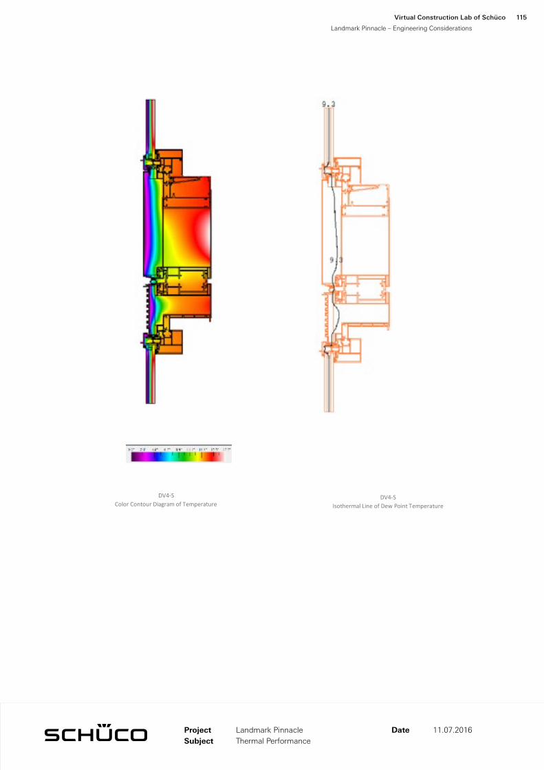
DV4-S Color Contour Diagram of Temperature
DV4-S Isothermal Line of Dew Point Temperature
ProjectSubject
Date 11.07.2016
Virtual Construction Lab of Schüco
Landmark Pinnacle – Engineering Considerations
115
Landmark PinnacleThermal Performance

System U-Factor Section of Elevation Evaluated
DH5
DV1
DV1
DV3
DV3
DV2
DV2
DV4
DV4
DH1 DH4 DH2 DH3
ProjectSubject
Date 11.07.2016
Virtual Construction Lab of Schüco
Landmark Pinnacle – Engineering Considerations
116
Landmark PinnacleThermal Performance

Horizontal System Component U-Value
Uf
[W/m2K]
Df
[m]
Ug
[W/m2K]
Dg
[m]
Up
[W/m2K]
Dp
[m]
Bf
[m]
U-Value
[W/m2K]
DH1 1.825 0.48 1.16 0.19 0.192 0.19 0.100 6.192
DH2 1.875 0.54 1.16 0.19 0.155 5.051
DH3 1.826 0.58 1.16 0.19 0.200 4.193
DH4 1.818 0.48 1.16 0.19 0.192 0.19 0.100 6.157
DH5-L 1.983 0.24 1.16 0.19 0.050 5.112
DH5-R 2.108 0.24 1.16 0.19 0.050 5.711
Vertical System Component U-Value
Uf
[W/m2K]
Df
[m]
Ug
[W/m2K]
Dg
[m]
Up
[W/m2K]
Dp
[m]
Bf
[m]
U-Value
[W/m2K]
DV1-LH 2.008 0.47 1.16 0.19 0.279 2.583
DV1-LS 1.597 0.69 1.16 0.19 0.536 1.656
DV1-RH 2.008 0.47 1.16 0.19 0.279 2.583
DV1-RS 1.597 0.69 1.16 0.19 0.536 1.656
DV2-H 1.697 0.47 1.16 0.19 0.192 0.19 0.278 1.931
DV2-S 1.417 0.69 1.16 0.19 0.192 0.19 0.504 1.441
DV3-H 2.530 0.47 1.16 0.19 0.279 3.463
DV3-S 2.142 0.69 1.16 0.19 0.503 2.513
DV4-H 2.941 0.47 1.16 0.19 0.278 4.157
DV4-S 2.083 0.69 1.16 0.19 0.503 2.431
ProjectSubject
Date 11.07.2016
Virtual Construction Lab of Schüco
Landmark Pinnacle – Engineering Considerations
117
Landmark PinnacleThermal Performance

Overall System Component U-Value
U-Value
[W/m2K]
Profile Width
[m]
Profile Length
[m]
A
[m2]
U * A
[W/K]
Panel 0.192 2.461 0.473
Glass 1.16 9.436 10.946
DH1 6.192 0.100 2.95 0.295 1.826
DH2 5.051 0.155 2.95 0.457 2.309
DH3 4.193 0.200 2.95 0.590 2.474
DH4 6.157 0.100 2.95 0.295 1.816
DH5-L 5.112 0.050 2.95 0.147 0.754
DH5-R 5.711 0.050 2.95 0.147 0.842
DV1-LH 2.583 0.279 1.135 0.316 0.817
DV1-LS 1.656 0.536 1.135 0.608 1.007
DV1-RH 2.583 0.279 1.035 0.288 0.745
DV1-RS 1.656 0.536 1.035 0.554 0.918
DV2-H 1.931 0.278 1.135 0.316 0.610
DV2-S 1.441 0.504 1.135 0.572 0.824
DV3-H 3.463 0.279 1.08 0.301 1.042
DV3-S 2.513 0.503 1.08 0.544 1.366
DV4-H 4.157 0.278 1.135 0.316 1.314
DV4-S 2.431 0.503 1.135 0.571 1.389
Overall 18.215 31.472
Overall System Results
Total Glass Area 9.436 m2
Total Panel Area 2.461 m2
Total Area 18.215 m2
Overall U-Value 1.728
W/m2K
ProjectSubject
Date 11.07.2016
Virtual Construction Lab of Schüco
Landmark Pinnacle – Engineering Considerations
118
Landmark PinnacleThermal Performance


Installation Methodology121

Installation Methodology
The system proposed here is designed to accommodate the installation of the façade works for the Landmark Pinnacle London project. All materials and units will be delivered to production stage “just-in-time” to allow for the most efficient logistics throughout the installation process. Unitised façade units will be prefabricated before delivery, protected in canvas covered stillages designed specifically for the UK market. The following sequence of activity is recommended for the building installation:
1. Unload units: Using a crane and forklift, the units will be unloaded from the trucking onto pallets. An Alimak HEK TPM 3000T2 is recommended for hoisting materials and units. This model is large enough to accommodate single and twin span units, acting with dual functionality as a transport platform or material hoist. Eight single panel units or four double panel units can be hoisted per lift, but neither will exceed the three tonnes load capacity.
Units brought to floors on pallets via material hoist
Eight total single panel units or four double panel units per hoist (will not exceed three tonnes)
Single panel units transferred from crates to tiptable for installation
Virtual Construction Lab of Schüco
Landmark Pinnacle – Installation Methodology
122

2. Installation of unitised façade at floor slab: An EMU glazing robot will be used to take the units from the crates to a tip table. From the tip table, the units will be attached to a spider crane from two floors above. The telescopic mechanism in the tip table will slide outwards with the unit during the installation.
3. Alignment of façade elements: Adjust-ments in the horizontal and vertical position are made as the unit is set. The temporary fixings supporting the unit to the anchor are removed after a unit is installed on top of the stack. The gaskets at the expansion joints are fixed, sealing the connection joints and edge connection.
Stack joint gasket installation
Adjustments in the horizontal and vertical position are made as the unit is set.
Single panel installation using a spider crane from above
Virtual Construction Lab of Schüco
Landmark Pinnacle – Installation Methodology
123

4. Shear Wall Installation: A monorail will be used to install units at the shear wall. The units will be picked from a tip table, using the same installation methodology as before with the unitised panels. Anchors and fixings will be done through a punched hole from the installation floor.
Shear wall installation using a monorail
Roof Terrance Installation Option A Crates lifted from truck to roof flooring
Roof Terrance Installation Option B Install directly from truck
Roof Terrance Installation Option A Install directly from truck
Virtual Construction Lab of Schüco
Landmark Pinnacle – Installation Methodology
124

Amenity level panels hoisted with tower crane to Floors 27 & 56
5. Amenity Wall Installation: There are two options for the amenity wall installation. The first is to use a tower crane to lift the bunked crates from the truck to the roofing. A scaffold and balustrade will be erected as a working platform and space. From there, the units will be installed from the roof using the tower crane. The second option is to install the units directly from the truck. This method is not as efficient in utilizing the tower crane, as 75% more ground to roof lifts will be required. For the amenity units on floors 27 and 56, we recommend using Preston Platforms to get the panels to the floor. They provide a large enough working and landing platform to get the oversized units to the amenity floors. These drops can be done out of hours to accom-modate and bring flexibility to the schedule.
Virtual Construction Lab of Schüco
Landmark Pinnacle – Installation Methodology
125


127Air & Water Infiltration

Air & Water Infiltration
Weathering performance of the curtainwall system is defined by an air and water primary line (plane) of demarcation between inside and out. Horizontally, this continuous barrier includes the exterior glass, its structural seal, the framing system, the framing internal seals, a horizontal primary gasket carried across unit joints and sealed at splices, and a silicone boot joining units and the primary gasket. Vertically, the barrier also includes glass, structural silicone, framing and seals, but the unit-to-unit seal is achieved through a vertical primary gasket sealed to the underside of the silicone boot and in contact with the primary horizontal seal gasket.
In the horizontal rainscreen, gaskets provide a first line of defense against water penetration by shielding the primary seal line and by creating a pressure equalized chamber in front of the primary seals.
This section diagrams the primary and secondary barrier lines of air and water infiltration for the key enclosure systems. Though only primary and secondary lines are shown, notice that a number of details have an additio-nal third line of defense against the elements.
The concept of the split-mullion unitized curtainwall system is a standard in the construction of mid and high-rise buildings. The process involves the fabrication of aluminum extrusions that are then assembled into frames and glazed with glass or other material (typically aluminum) panels under factory-controlled conditions. The units are then shipped to the site, hoisted into position, and hung off the building structure, where the split-mullions interlock to form a weather seal. In this section, the following weathering characteristics of the unitized curtainwall are discussed:
1. Water Penetration
2. Vapor Barrier Control
3. Condensation Control
4. Air Infiltration
Water Penetration
Water penetration through a barrier is the result of the single or combined effect of three factors; an opening through the barrier; capillary action on the wall surface; a pressure difference across the barrier as the result of wind. Eliminating any one of these factors can prevent water penetration. Curtainwalls need to move, therefore it is not possible to close all openings. It is also very difficult to keep curtainwalls dry at all times. Controlling the third factor—pressure differential—has proven to be the most practical strategy. The concept of the rain-screen was introduced in the early 20th century and was adopted by the curtainwall industry in the 1960s as a primary means of preventing water penetration. The concept, generally referred to as pressure equalized rainscreen (PER) is illustrated in Figure 1 above.
The PER concept is simple. If there is pressure equilibri-um between the outside and the air chambers of the extrusions (Po=Ps), any water penetrating the rain-screen will be drained through the chambers to the outside.
Stack Joint
The stack joint is the mating interface between upper and lower curtainwall units. It accommodates vertical movements imposed by structural live load deflections, temperature induced movements, and allowance for racking of the units during a seismic event. As a result the design of stack joint requires a high degree of articulation as well as the ability to maintain water and air seals. The concept of rainscreen is utilized in the design of the stack joint. A bulb gasket with positive con-tinuous contact is placed in between the sill engagement grove and the head attachment gusset to insure a reliable air and water barrier. The outermost line of defense (in this case tertiary) is provided by creation of a pressure-equalized chamber in front of this air barrier using an exterior wiper gasket (see Figure 2). The pressure inside this chamber is equalized to the pressure outside through openings at quarter-points on the wiper flaps. This system will eliminate the migration of moisture due to pressure differential between the exterior wall and rainscreen cavity. In addition, the tertiary barrier is designed to prevent the movement of
Virtual Construction Lab of Schüco
Landmark Pinnacle – Air & Water Infiltration
128

Figure 1 - Pressure Equalized Rainscreen (PER)
Figure 2 - Glazing Pocket
Virtual Construction Lab of Schüco
Landmark Pinnacle – Air & Water Infiltration
129

moisture due to capillary action, as well as providing protection against water penetration due to kinetic energy (driving rain) or other means of transport such as air stream or gravity.
Vertical Mullions
The diagram on page 132 represents the weathering system for the typical vertical split mullions. A two barrier system is also utilized here against water penetra-tion. The primary water/air barrier is located at the back of the mullion, running along the outside face of glass and bridging the joint along the field-applied wet-seal. This is once again the result of the unique interior seal condition. For the secondary vertical, continuous contact is established at the gasket between aluminum compo-nents.
Horizontal Mullions
Horizontal mullions are factory sealed and designed with two lines of protection; the primary line of defense is the silicone caulk line factory applied at the glass joint. The secondary line of defense is the metal extrusion, which is mechanically fastened to the vertical mullions. All the joinery connections are sealed using silicone joinery pads or factory applied silicone.
Glazing Pocket
Glazing pockets are drained to the outside using draina-ge holes on quarter-points of the horizontal span, or the corner points (see Figure 2).
Vapor Barrier Control
Vapor diffusion through an exterior wall is sometimes the cause of cavity wall wetness or condensation in winter. However, because unitized curtainwalls have compo-nents that are resistant to vapor diffusion (aluminum extrusions, glass, sheet metal panels, and gaskets), cavity moisture due to diffusion is not a concern.
Curtainwall Interface Details
As a standard practice, all interface conditions provided by Schüco systems employ redundancy through a strategy of primary and secondary protection barriers.
Virtual Construction Lab of Schüco
Landmark Pinnacle – Air & Water Infiltration
130

Condensation Control
To be resistance to condensation the unitized aluminum curtainwall must incorporate various features, such as quality thermal breaks for the aluminum frames, double glazing for the vision area, and an insulated metal panel in spandrel areas. Connections and fasteners may also include thermal breaks or thermal separators. The condensation resistance of the curtainwall in winter is governed by the indoor conditions of temperature and relative humidity, and the outdoor temperature. In summer, the condensation resistance of the aluminum curtainwall is governed by the outdoor temperature, the outdoor relative humidity, and the indoor air-conditioned temperature. Condensation occurs on the glass or aluminum surfaces when the humidity of the surround-ing air comes in contact with a cold surface and changes from a vapor to a liquid. Most of the unitized systems utilize thermal breaks to deal with the condensation issue. The Schüco system also provides a weep gutter at the stack joint. This feature offers an extra measure of protection against condensation. The weep-hole is only utilized in geographic regions of extreme climate or with facade specifications that require protection against humidity levels of 40% or more (see thermal perfor-mance report).
Air Infiltration
Air leakage at the glass/aluminum joint is minimized with either a wet silicone seal or a dry silicone gasket. In an unitized system, the mullions are split and therefore include an additional air barrier joint between the half mullions. Unitized systems perform well to common air infiltration standards (0.06 cfm psf at 6.24 psf pressure difference).
Virtual Construction Lab of Schüco
Landmark Pinnacle – Air & Water Infiltration
131

DBZ
_6/4
,5
M 1
2 D
IN 1
25A
M 12 x 20 DIN 933
M 12 x 20 D
IN 933
Unit 1DV1
POutside POutside
Virtual Construction Lab of Schüco
Landmark Pinnacle – Air & Water Infiltration
132

DBZ
_6/4
,5
M 1
2 D
IN 1
25A
M 12 x 20 DIN 933
M 12 x 20 D
IN 933
Primary Air / Water Barrier Line
Secondary Air / Water Barrier Line
PInside
Virtual Construction Lab of Schüco
Landmark Pinnacle – Air & Water Infiltration
133

© 2016 Virtual Construction Lab of Schüco


Virtual Construction Lab of Schuco1460 Broadway, New York, NY 10036 www.schueco.us