ProMAX® Seismic Datasets - Landmark Software Manager
30
Other Docs Known Problems Search Page ProMAX® Seismic Datasets This chapter explains what a ProMAX® seismic dataset is and how to work with both disk and tape datasets. In This Chapter ➲ ProMAX® Dataset Overview 89 ➲ Creating ProMAX® Datasets 92 ➲ Accessing ProMAX® Datasets 106 ➲ Working with ProMAX® Disk Datasets 108 ➲ Working with ProMAX® Tape Datasets ➲ New 3D Seismic Data Formats 115
-
Upload
khangminh22 -
Category
Documents
-
view
0 -
download
0
Transcript of ProMAX® Seismic Datasets - Landmark Software Manager

ProMAX® Seismic Datasets
This chapter explains what a ProMAX® seismic dataset isand how to work with both disk and tape datasets.
In This Chapter
➲ ProMAX® Dataset Overview 89
➲ Creating ProMAX® Datasets 92
➲ Accessing ProMAX® Datasets 106
➲ Working with ProMAX® Disk Datasets 108
➲ Working with ProMAX® Tape Datasets
➲ New 3D Seismic Data Formats 115
Other Docs Known ProblemsSearch Page

ProMAX® Dataset Overview90 ProMAX® Reference
ProMAX® Dataset Overview
A ProMAX® dataset contains your actual trace data as it isstored within the ProMAX® processing system. Whether youare working with disk or tape, ProMAX® datasets consist offour file types: Index, Map, Trace Data, and Trace Headers.
ProMAX® Dataset Storage
The Index, Map, Trace Data, and Trace Header files arelocated in the Line and Dataset subdirectories, at least untilyou output to tape.
Here is an example of the directory structure syntax forprocessing one dataset with one flow. This example does notinclude all 10 of the database subdirectories, only two:
See the Working with ProMAX® Tape Datasets section for anexplanation of how the system outputs a dataset to tape.
If your dataset resides on disk, your dataset will be located inthe following subdirectories and contain the following files:
Location of Disk Dataset Files
PROMAX_DATA_HOME
/Area subdirectory
/Line subdirectory
/Flow subdirectory
Dataset files (Index and Map)
/Database subdirectory
Parameter Table files
/Dataset subdirectory
Database files
Flow files
Dataset files (Header and Trace)
/Database subdirectoryDatabase files
/Data subdirectoryor
ProMAX®Dataset
Other Docs Known ProblemsSearch Page

ProMAX® Dataset Overview91 ProMAX® Reference
How the ProMAX® software Names Files within a ProMAX®Dataset
The ProMAX® processing system names the files within adataset in the following way:
Index and Map Files
The system writes the Index and Map files to a Linesubdirectory. Each of these filenames begins with an 8-digitnumber, which is generated by a hash routine; this numberis based on the first 14 characters of your ProMAX® datasetname. The letter C and an abbreviation for the file type follow
File Naming Conventions
File Type Naming Convention
Index <8-digit number>CIND
Map <8-digit number>CMAP
Trace Data <8-digit number>/TRCx
Trace Header <8-digit number>/HDRx
/Line1
/<8-digit number>HDR1HDR2TRC1TRC2
DescName<8-digit number>CIND<8-digit number>CMAP
Index andMap files
Trace andHeader files
Linesubdirectory
Datasetsubdirectory
Files Within a ProMAX® Dataset
/Area
Other Docs Known ProblemsSearch Page

ProMAX® Dataset Overview92 ProMAX® Reference
this 8-digit number. (See the File Type Naming Conventionstable above)
If you output your data to tape, these files will reside on thefirst volume of the dataset, and the most current Index filewill be written to the end of the tape.
Trace Data and Trace Header Files
Your Trace Data and Trace Header files are written to aDataset subdirectory, which sits one level below the Linesubdirectory. The system names the Dataset subdirectory thesame 8-digit number that precedes your Index and Mapfilenames. The system names your Trace Data and TraceHeader files by ending the name with an abbreviation for thefile type and an additional number, which we explain in theOutputting ProMAX® Disk Datasets section. (See the File TypeNaming Conventions table above.)
The Map and Index files store information about the dataset.This information gives you the ability to access traces in anon-sequential order. These files also make it possible for youto access information about the Dataset without having tomount a tape.
Note: The ProMAX® system writes Trace Data and TraceHeader files in pairs.
Other Docs Known ProblemsSearch Page

Creating ProMAX® Datasets93 ProMAX® Reference
Creating ProMAX® Datasets
The system uses a proprietary dataset format that is tailoredfor interactive processing and random disk access (traversinga disk). When you execute one of the input and/or outputprocesses, the system reformats your dataset to ourproprietary format, which consists of four file types: Index,Map, Trace Data, and Trace Headers. These files contain thefollowing information.
Index File
This file contains information that relates to the entiredataset, such as sample intervals, number of samples pertrace, processing history, and names of trace header entries.The format is free form. This file may get bigger as youprocess.
If you output your data to tape, these files will reside on thefirst volume of the dataset as well as in the Line subdirectory.Additionally, the most current Index file will be written to theend of the tape.
Map File
This file ties the dataset to the database. It creates asequential trace order and keeps track of the trace locations.Given a particular trace number, it will find the sequentialtrace number within the dataset. This allows very rapidaccess of traces during processing. The map may get biggeras you process.
Trace Data File
This file contains the actual sample values for the data trace.
Trace Header File
Trace headers are the primary form of intertoolcommunication. A Trace Header file contains the headerentries that correspond to a particular Trace Data file. Bystoring the trace headers in a separate file, you can sort thetrace headers without skipping past the seismic data
Other Docs Known ProblemsSearch Page

Creating ProMAX® Datasets94 ProMAX® Reference
samples. The header files may get bigger as you add newheader entries.
Trace Headers as a Communication Tool
When a flow is initially executed, nothing exists in the traceheader. All trace header entries are created duringinitialization phase, primarily by the input tool, which hasthe special responsibility of creating all of the header entriesthat existed when a dataset was written out in a prior flow.Individual tools then add new Trace Headers as needed. Youcan add defined trace header entries using the Trace HeaderMath tool.
Because of the way trace headers work, we created theconcept of an ensemble. An ensemble is defined as anycollection of traces that share the same primary sort key.Shot records, CDP gathers, and common-receiver gathers areexamples of ensembles. All of the traces within an ensemblehave the header entry END_ENS (End of Ensemble) set to 0(false) except the last trace, which is set to 1 (true). Withstacked data, every trace is treated as an individualensemble, so all traces have their END_ENS flag set to 1(true)
The following rules apply to trace header entries:
• All standard Trace Header entries are one word inlength. Trace headers are very flexible, and individualentries may have any length, order, or format. This hasproved to be a tremendous benefit in accommodatingnew ideas as the system evolves. The term trace headerentry is a better description than trace header wordbecause it avoids the connotation of fixed length.
• The format of the individual entries can vary. Currentlysupported formats are integer, real, double precision real(seldom used), logical (seldom used), and character(stuffed into integers). Each header entry can actually bean array of values, although the length must be a wholenumber of words. Complicated entities such as C structscan also be included in the trace headers.
• Header entries that you should not modify, except indi-rectly, contain an asterisk in the description. Think ofthese as read-only.
• All times are in ms.
Other Docs Known ProblemsSearch Page

Creating ProMAX® Datasets95 ProMAX® Reference
• All elevations are relative to sea level and should be neg-ative for headers such as the source elevation in marineshooting.
• It is the convention within the ProMAX® processing sys-tem that a negative static shifts data up (towards time0.0), and a positive static shifts data down (away fromtime 0.0).
• Other standard header entries may be added in futurereleases.
Guaranteed Headers
There is a subset of the standard trace header entries knownas the guaranteed headers, which are always guaranteed toexist in a flow, although their positions may vary.
The names, descriptions, and initial values of these headersare as follows:
Guaranteed Headers
Header Description
SEQNO Sequence number in ensemble (variable)
END_ENS End-of-ensemble flag (variable)
EOJ End-of-job flag (variable)
TRACENO Trace number in seismic line
TRC_TYPE Trace type (data, aux, etc.)
TLIVE_S Start time of live samples
TFULL_S Start time of full samples
TFULL_E End time of full samples
TLIVE_E End time of live samples
LEN_SURG Length of surgical mute taper
TOT_STAT Total static for this trace
NA_STAT Portion of static not applied
AMP_NORM Amplitude normalization factor
Other Docs Known ProblemsSearch Page

Creating ProMAX® Datasets96 ProMAX® Reference
Available Headers
The following table lists all currently defined trace headerentries in alphabetical order, followed by a sequentialnumber. The sequential number corresponds to the orderthat we describe each header at the end of this table.
TR_FOLD Current trace fold
SKEWSTAT Multiplex skew static correction
LINE_NO Line number (hashed line name)*
LSEG_END Line segment end*
LSEG_SEQ Line segment sequence number*
Alphabetical List of Available Headers
AMP_NORM (13) AOFFSET (47) CDP(24) CDP_ELEV (45)
CDP_NFLD (25) CDP_SLOC (30) CDP_X (41) CDP_Y (42)
CHAN (22) CR_STAT (66) CS_STAT (65) CMP_X (43)
CMP_Y (44) DEPTH (37) DISKITER (16) DMOOFF (80)
DS_SEQNO (17) END_ENS (1) EOJ (3) FB_PICK (70)
FFID (21) FILE_NO (19) FK_WAVEL (78) FK_WAVEN (77)
FNL_STAT (61) FRN_TRNO (8) FT_FREQ (79) GEO_COMP (50)
ILINE_NO (53) LEN_SURG (75) LINE_NO (7) LSEG_END (9)
LSEG_SEQ (10) NA_STAT (57) NCHANS (23) NDATUM (58)
NMO_APLD (15) NMO_STAT (60) OFB_CNTR (49) OFB_NO (48)
OFFSET (46) PARMTEST (6) PR_STAT (68) PS_STAT (67)
REC_ELEV (33) REC_H2OD (39) REC_NFLD (29) REC_SLOC (26)
Guaranteed Headers
Header Description
Other Docs Known ProblemsSearch Page

Creating ProMAX® Datasets97 ProMAX® Reference
System-related Headers
1. END_ENS: End-of-ensemble flag* (integer). An ensemble isdefined within the exec as any collection of traces(normally) sharing the same primary sort key. Typicalexamples are shot records, CDP gathers, and common-receiver gathers. All of the traces within an ensemble haveENS_ENS set to false (NLAST), except the last trace, set totrue (LASTTR). The global variable MAXDTRz is themaximum number of traces per ensemble matching thenumber of contiguous traces with ENS_ENS set to NLAST.
2. SEQNO: Sequence number in ensemble (integer) is thesequence number of an individual trace within the currentensemble.
3. EOJ: End of job flag* (integer) is set to false (NLAST) forevery trace in a flow. However, under certaincircumstances, complex tools receive a dummy trace (andtrace header) with EOJ set to true (LASTTR). The dummytrace (and trace header) should not be returned by thecomplex tool.
4. TRACENO: Trace number in seismic line* (integer) is aninternal reference number that is assigned by the systemwhen the database is initialized. It represents the uniquesequential trace number within the dataset that is used to
REC_STAT (63) REC_X (31) REC_Y (32) REPEAT (5)
R_LINE (56) SEQNO (2) SEQ_DISK (18) SG_CDP (81)
SIN (11) SKEWSTAT (62) S_LINE (55) SLC_TIME (83)
SMH_CDP (82) SOURCE (20) SOU_COMP (51) SOU_ELEV (36)
SOU_H2OD (40) SOU_SLOC (27) SOU_STAT (64) SOU_X (34)
SOU_Y (35) SRF_SLOC(28) SR_AZIM (52) TFULL_E (73)
TFULL_S (72) TLIVE_E (74) TLIVE_S (71) TOT_STAT (59)
TRACENO (4) TRC_TYPE (12) TRIMSTAT (69) TR_FOLD (14)
UPHOLE (38) WB_TIME (76) XLINE_NO (54)
Alphabetical List of Available Headers
Other Docs Known ProblemsSearch Page

Creating ProMAX® Datasets98 ProMAX® Reference
initialize the database. TRACENO is undefined (and set toINULL) after stack. The value of TRACENO in the headersis used to reference the TRC ordered parameter file in theparameter database if the global variable ITRNO_VALIDz istrue (=1).
5. REPEAT: repeated data copy number (integer) is set byReproduce Traces to reflect the copy number whenensembles or all data is repeated. (Subsequent processingfrequently keys on REPEAT copy number for purposes ofcomparison.) Reproduce Traces creates and sets theheader REPEAT_T when traces are repeated on anindividual basis.
6. PARMTEST is an alpha header word that can be createdby Trace Display Label or is automatically generated byParameter Test. The value stored in the header isdisplayed in the Trace Display window.
7. LINE_NO: Line number (hashed line name)* (integer)represents the hashed line (or survey) name used touniquely identify lines. Individual inlines and crosslines ofa 3D survey are part of the same survey and have thesame LINE_NO. LINE_NO is used in operations involvingprocessing or storage of data from multiple lines.GeoQuest IES Input over-rides LINE_NO to reflect thehashed line name of the IES line. In that case, eachversion number of each inline or crossline receives adifferent LINE_NO.
8. FRN_TRNO: Foreign trace-number-within line (integer) isused to store trace numbers from non-ProMAX® sourcesand distinguish between traces with a common LINE_NO.
9. LSEG_END: Line segment end* (integer) is defined as aportion of the data in a flow (including all of the data) thatshould be processed as a continuous piece. For example,if two different lines were read into the same flow and arunmix is applied, LSEG_END is used to ensure that datawas not smeared from one line into the next. LSEG_ENDis set to false (NLAST) for all traces except the last trace ina segment, set to true (LASTTR). When multiple lines areimported via GeoQuest IES Input, LSEG_END is set to
Other Docs Known ProblemsSearch Page

Creating ProMAX® Datasets99 ProMAX® Reference
true for the last trace of each inline, crossline, time slice,reconstruction cut, or 2D line.
10. LSEG_SEQ: Line segment sequence number* (integer) isthe sequence number of the current line segment in aprocessing flow. See discussion of LSEG_END.
11. SIN: Source index number (internal)* (integer) is aninternal reference number that is assigned by the systemwhen the database is initialized. It represents the uniquesequential source number (including test records, badshots, etc.) within the dataset used to initialize thedatabase. The value of SIN in the headers is used toreference the SIN ordered parameter file in the parameterdatabase, if the global variable IGEOM_MATCHz is true(=1).
12. TRC_TYPE: Trace type (data, aux, etc.) (integer) is usedmost commonly to distinguish between live traces, deadtraces, and auxiliary traces. Flag value 1 represents a livetrace. Flag value 2 represents a dead trace. Flag value 3represents an auxiliary trace. Other valid trace typesinclude dummy, time break, uphole, sweep, timing, waterbreak, and unknown (other).
13. AMP_NORM: Amplitude normalization factor (real) isdefined as the average amplitude normalization applied toa trace. For example, if a time-variant gain increased theamplitude of each sample of a trace by an average factor of2.0, then it should also multiply the value of AMP_NORMby 2.0.
14. TR_FOLD: Actual trace fold (real) is the number of tracessummed to form the current trace. TR_FOLD shouldreflect the actual number of traces summed, even if thetheoretical fold is different (in a process such as aweighted stack). TR_FOLD is not an integer.
15. NMO_APLD: determines if NMO is applied to the traces.
Input-related Headers
16. DISKITER: Disk Data Input iteration* (integer) reflects thecurrent iteration number, if Disk Data Input or TapeData Input reads through the data multiple times.
17. DS_SEQNO: Input dataset sequence number* (integer)reflects which dataset a trace was originally read from, if
Other Docs Known ProblemsSearch Page

Creating ProMAX® Datasets100 ProMAX® Reference
Disk Data Input or Tape Data Input are reading multipledatasets.
18. SEQ_DISK: Trace sequence number from disk (integer)reflects the actual sequence number that a trace was readfrom tape or disk, if the input tool was Disk Data Input orTape Data Input. SEQ_DISK is unique for every inputtrace, even in the case of multiple iterations or multipledatasets. For example, if a dataset containing 10 traces isread twice, on the second iteration the first trace hasSEQ_DISK equal to 11.
19. FILE_NO: Sequential file number.
Geometry-related Headers
20. SOURCE: Live source number (user-defined) (integer) isassigned when the geometry is written and installed. Itrepresents a number to refer to a given record. SINs thatare not assigned a SOURCE number are not part of thelive data, and have SOURCE set equal to INULL.
21. FFID: Field file ID number (integer) of each SIN isextracted from the headers of the field data and stored inthe parameter database. It is largely unused because itcannot be assumed to be unique.
22. CHAN: Recording channel number (integer) of each traceis extracted from the headers of the field data. CHAN isone of the few headers for which the values from the fielddata are trusted (although they can be corrected if inerror). CHAN numbers is used to reference the CHNordered parameter file in the parameter database if theglobal parameter IGEOM_MATCHz is true (=1).
23. NCHANS: Number of channels of source (integer) isdefined as the number of channels found within the SINbelonging to the current trace. This is a seldom-usedheader entry.
24. CDP: CDP bin number (integer) (also known as CMP) isassigned by the selected binning method. The incrementbetween CDP numbers can be greater than one. CDPnumbers are used to reference the CDP ordered parameter
Other Docs Known ProblemsSearch Page

Creating ProMAX® Datasets101 ProMAX® Reference
file in the parameter database if the global variableIGEOM_MATCHz is true (=1).
25. CDP_NFLD: Number of traces in CDP bin (integer) is thefold of the trace CDP. This is a seldom-used header entry.
26. REC_SLOC: Receiver index number (internal)* (integer) isan internal reference number that is assigned when thedatabase is initialized. It represents the unique sequentialreceiver number within the dataset used to initialize thedatabase. The value of REC_SLOC in the headers are usedto reference the SRF ordered parameter file in theparameter database if the global variable IGEOM_MATCHzis true (=1).
27. SOU_SLOC: External source location number(integer) istypically the field station number assigned to sources. Itmay or may not be on a similar station grid as thereceivers. See SRF_SLOC.
28. SRF_SLOC: External receiver location number (integer) istypically the field station number assigned to receiverpositions. It may or may not be on a similar station grid asthe sources. See SRF_SLOC.
29. REC_NFLD: Receiver fold (integer). REC_NFLD is the foldof the receiver gather at which the current trace wasrecorded. This is a seldom-used header entry.
30. CDP_SLOC: External CDP location number (integer) istypically the field station number assigned to CDPlocations. It may or may not be on a similar station grid asthe sources and receivers.
31. REC_X: Receiver X coordinates (real) are always the actualcoordinates, not the receiver surfloc coordinates (if theyare not coincident, as in the case of marine 3D). Allcoordinates are relative to reference coordinates in theparameter database (XREFz and YREFz).
32. REC_Y: Receiver Y coordinate (real). See discussion ofcoordinates under REC_X.
33. REC_ELEV: Receiver elevation (real) should reflect theactual receiver elevation, and not the elevation of thesurface at the receiver X,Y (if the receiver is in a borehole).For marine shooting, REC_ELEV reflects the water depth
Other Docs Known ProblemsSearch Page

Creating ProMAX® Datasets102 ProMAX® Reference
of the cable and is a negative number. See furtherdiscussion of coordinates under REC_X.
34. SOU_X: Source X coordinate (real) are always the actualcoordinates, not the coordinates of the nearest surfloc. Allcoordinates are relative to reference coordinates in theparameter database (XREFz and YREFz).
35. SOU_Y: Source Y coordinate (real). See discussion ofcoordinates under SOU_X.
36. SOU_ELEV: Source elevation (real). SOU_ELEV is theelevation of the SURFACE at the X,Y of the source (anddoes not reflect a hole depth - see DEPTH). However,marine shooting SOU_ELEV reflects the water depth of thesource and is a negative number. See further discussion ofcoordinates under SOU_X.
37. DEPTH: Source depth (real) is the HOLE depth of thesource. It is 0.0 if no hole exists. DEPTH is 0.0 for marineshooting, regardless of the water depth of the source.
38. UPHOLE: Source uphole time (real) is the uphole timeobserved for a buried source.
39. REC_H2OD: Water depth at receiver (real) is the waterdepth at the X,Y of the receiver in marine shooting, but isnot routinely assigned.
40. SOU_H2OD: Water depth at source (real) is defined thewater depth at the X,Y of the source in marine shootingbut is not routinely assigned.
41. CDP_X: X coordinate of CDP (real) is the bin center. Allcoordinates are relative to reference coordinates in theparameter database (XREFz and YREFz).
42. CDP_Y:- Y coordinate of CDP” (real). See discussion ofCDP_X.
43. CMP_X: X coordinate computed as the average of the shotand receiver X coordinate for a trace.
44. CMP_Y: Y coordinate computed as the average of the shotand receiver Y coordinate for a trace.
45. CDP_ELEV: Elevation of CDP (real) are problematicbecause they are not specified and can be difficult tointerpolate. Historically, the elevation of each CDP wastaken as the elevation of the nearest surfloc. The
Other Docs Known ProblemsSearch Page

Creating ProMAX® Datasets103 ProMAX® Reference
elevations of CDPs are interpolated from the elevations ofsurflocs.
46. OFFSET: Signed source-receiver offset (real) is theseparation between source and receiver for a given trace.If the source is at a lower surfloc than the receiver, theoffset is positive. Otherwise, the offset is negative (theconvention is the same for 3D, although the sign ofOFFSET has little meaning).
47. AOFFSET: Absolute value of offset (real) is literallyabs(OFFSET). It is a convenience for specifyingparameters in some situations.
48. OFB_NO: Offset bin number (integer) represents thesequential bin number of offset bins created duringgeometry installation. OFB_NO is used to reference theOFB ordered parameter file in the parameter database ifthe global variable IGEOM_MATCHz is true (=1).
49. OFB_CNTR: Offset bin center (real) represents the offset ofthe center of an offset bin. See discussion of OFB_NO.
Special Geometry-related Headers
50. GEO_COMP: Geophone component (x,y, z) (integer is setto 1 for the vertical component of motion, 2 for the east-west (or inline for 3D) component of motion, and 3 for thenorth-south (or crossline for 3D) component of motion inmulticomponent recording.
51. SOU_COMP: Source component (x,y,z) (integer) is set to 1for the vertical component of motion, 2 for the east-west(or inline for 3D) component of motion, and 3 for thenorth-south (or crossline for 3D) component of motion inmulti-component shooting.
52. SR_AZIM: Source to receiver azimuth (real) is defined asthe azimuth from the source to the receiver, clockwise,where 0.0 is north (or the Y axis of the 3D surveycoordinate system). The units are radians.
53. ILINE_NO: 3D inline number (integer) is the number of thecommon inline that a trace belongs, where inlines andcrosslines are defined by the CDP binning, but the inlinedirection is the direction of source motion (if applicable).For example, in a marine 3D survey, a single sail line with
Other Docs Known ProblemsSearch Page

Creating ProMAX® Datasets104 ProMAX® Reference
a single streamer tends to produce a set of traces with acommon INLINE_NO but varying XLINE_NO.
54. XLINE_NO: 3D crossline number (integer) is the number ofthe common crossline that a trace belongs. See thediscussion of ILINE_NO.
55. S_LINE: Swath or sail line number (integer) is to furtherdenote a source station number. Source station numberscan repeat between land swath or marine sail lines.
56. R_LINE: Receiver line number (integer) is to further denotea receiver station number. Receiver station numbers canrepeat between cable or spread lines.
Statics-related Headers
57. NA_STAT: Portion of static not applied* (real). Forefficiency, and to avoid the effects of multipleinterpolations, statics are normally not fully appliedwithin the ProMAX® processing system, except to thenearest whole sample interval. NA_STAT represents thefractional sample portion of the static that is not applied.It is applied during NMO in normal processing. ApplyFraction Statics can also be used for this purpose.
58. NDATUM: the value of the smooth surface or Floating(NMO) Datum used to compute the CDP mean static.
59. TOT_STAT: Total static for this trace* (real) represents thetotal static to apply to the trace minus NA_STAT. It is usedto remove previously applied statics.
60. NMO_STAT: NMO datum static (don’t apply) (real) is thestatic applied to move from the surface to the NMOdatum.
61. FNL_STAT: Static to move to final datum (real) is the staticapplied to move from the NMO datum to the final datum.This is typically applied after CDP stack by the stackingtool.
62. SKEWSTAT: Multiplex skew static (real) is the multiplexskew static (channel static due to differential delays inolder recording systems) assigned during input of the fielddata.
63. REC_STAT: Total static for receiver (real) is the portion ofTOT_STAT attributed to the receiver (from elevationstatics). This attribute is not equal to R_STATIC in the
Other Docs Known ProblemsSearch Page

Creating ProMAX® Datasets105 ProMAX® Reference
SRF database in the standard sequence. It is normally leftat 0.0
64. SOU_STAT: Total static for source (real) is the total portionof TOT_STAT attributed to the source (from elevationstatics).This attribute is not equal to S_STATIC in the SINdatabase in the standard sequence. It is normally left at0.0
65. CS_STAT: Corr. autostatics source static (real) is thesource static computed by a correlation autostaticsprogram. It is a convenience for parameterization of theprocess that applies autostatics solutions to the data.
66. CR_STAT: Corr. autostatics receiver static (real) is thereceiver static computed by a correlation autostaticsprogram. See also CS_STAT.
67. PS_STAT: Power autostatics source static (real) is thesource static computed by a power autostatics program. Itis a convenience for parameterization of the process thatapplies autostatics solutions to the data.
68. PR_STAT: Power autostatics receiver static (real) is thereceiver static computed by a power autostatics program.See also PS_STAT.
69. TRIMSTAT: Trim static (real) is the static computed by atrim statics (non-surface consistent) program.
70. FB_PICK: First break pick time (real) is the first break picktime of the trace.
Mute-related Headers
71. TLIVE_S: Start time of live samples (real) is the time of thefirst live (non-zero) sample, if a top mute is applied. Thedifference between TFULL_S and TLIVE_S indicates thetaper length of a top mute, if one was applied. The value ofTLIVE_S does not enter the equation for conversion fromsample number to time, or vice versa (it is not a recordingdelay time).
72. TFULL_S: Start time of full samples (real) is the time of thefirst full untapered sample, whose amplitude is totallyunaffected by a top mute. The difference between
Other Docs Known ProblemsSearch Page

Creating ProMAX® Datasets106 ProMAX® Reference
TFULL_S and TLIVE_S indicates the taper length of a topmute.
73. TFULL_E: End time of full samples (real) is the time of thelast full untapered sample, whose amplitude is totallyunaffected by a bottom mute. The difference betweenTLIVE_E and TFULL_E indicates the taper length of abottom mute.
74. TLIVE_E: End time of live samples (real is the time of thelast live (non-zero) sample, if a bottom mute was applied.The difference between TLIVE_E and TFULL_E indicatesthe taper length of a bottom mute.
75. LEN_SURG: Length of surgical mute taper (real) indicatesthe length of the taper of a surgical mute. If multiplesurgical mutes are applied with different taper lengths,LEN_SURG represents the last applied.
76. WB_TIME: Water bottom time (real) is the time loaded forsources and/or receiver CDP. This is a mute header formultiple rejection.
Special Applications-related Headers
77. FK_WAVEN: Wavenumber of F-K domain trace (real)represents the common wavenumber of a series ofamplitudes (a trace), after transformation to the F-Kdomain.
78. FK_WAVEL: Wavelength of F-K domain trace (real)represents the common wavelength of a series ofamplitudes (a trace), after transformation to the F-Kdomain.
79. FT_FREQ: Frequency of F-T domain trace (real) representsthe common frequency of a series of amplitudes (a trace),after conversion to the F-T domain.
Other Docs Known ProblemsSearch Page

Creating ProMAX® Datasets107 ProMAX® Reference
80. DMOOFF: Offset bin for DMO (real) represents the offsetof a common offset bin created for purposes commonoffset DMO.
81. SG_CDP: Super Gather CDP number is created by theSupergather formation processes and is set to the centerCDP of the supergather.
82. SMH_CDP is created by the Supergather formationprocesses and is set to the number of CDPs combined tojoin the Supergather.
83. SLC_TIME is created by Time Slice Input and containsthe time of the time slice. This trace header can also beused for annotation by using a primary annotation ofslc_time in Trace Display.
Other Docs Known ProblemsSearch Page

Accessing ProMAX® Datasets108 ProMAX® Reference
Accessing ProMAX® Datasets
You can access ProMAX® datasets by selecting Datasetsfrom the Flows menu or from within any process requiring adataset selection, such as Disk Data Input.
The Dataset window lists the datasets in the current Linesubdirectory. The types of information about each dataset isconfigured via the Config option at the bottom of the FlowBuilder window.
The datasets menu bar has the following options:
• Delete: Delete a seismic dataset. You are prompted witha confirmation.
Caution: You cannot restore a deleted dataset.
• Add: Add a new seismic dataset. When you move thecursor out of the box, the dataset description is added tothe menu.
• Rename: Rename a seismic dataset. Type in a new namefor the selected seismic dataset. When you move the cur-sor out of the box, the selected dataset is renamed.
• Copy: Copy a seismic dataset. Select an Area, Line, anddataset to copy a seismic dataset. Enter a name for thenew seismic dataset. If you move the mouse out of thebox without entering a name, the new seismic dataset isgiven the same name as the dataset from which it wascopied.
• Listing: Dumps a list of the datasets to a user-specifiedfile.
Click MB2 on a dataset to display expanded tape and diskdataset information: the size of the dataset file in bytes, dateand time created, last changed and last accessed, the datatype, unstacked or stacked, the data domain, the primaryand secondary sort keys, the total number of traces, numberof samples per trace, sample rate, the geometry flag, theminimum and maximum CDP, and shot index numbers.
Click MB3 anywhere on a dataset to display the HistoryViewer. This gives a detailed processing history for thisdataset. For additional information on using the History
Other Docs Known ProblemsSearch Page

Accessing ProMAX® Datasets109 ProMAX® Reference
Viewer, see the Viewing the Processing History of a Datasetsection in the Working with ProMAX® chapter.
You can leave the Datasets Menu at any time by moving themouse cursor to the top of the menu. You are taken back tothe Flow menu.
Other Docs Known ProblemsSearch Page

Working with ProMAX® Disk Datasets110 ProMAX® Reference
Working with ProMAX® Disk Datasets
In a default ProMAX® configuration, all seismic dataset filesreside on a single disk partition. You can set the location ofthis in the $PROMAX_HOME/etc/config_file.
A typical Dataset might contain the following files:
/advance/data/usertutorials/landexample/78252353CIND
/advance/data/usertutorials/landexample/78252353CMAP
/advance/data/usertutorials/landexample/78252353/TRC1
/advance/data/usertutorials/landexample/78252353/HDR1
You can output all of your dataset files to primary storage.However, you cannot output all of your dataset files tosecondary storage, only Trace Data and Trace Header files.
As datasets are output, the system monitors the size of theTRCx/HDRx pairs. When the size exceeds the definedmaximum number of megabytes, the system writes anotherpair of TRCx and HDRx files to the next available storagepartition as determined by settings in the config_file. See theOverriding Environment Variable Settings section in theSystem Administration guide for setup information.
Outputting to Primary Storage
The ProMAX® system writes your Index and Map files toprimary storage only. In addition, your primary storagepartition will typically contain your Trace Data and TraceHeader files, Flow subdirectories, Parameter Tables, OPFs,and various miscellaneous files.
Under the default configuration, the system writes the initialTRCx and HDRx files to the primary storage partition.However, you can override this behavior by setting the skipparameter disk partition parameter in Disk Data Output. Ifyou set this parameter to Yes, then the system will not writeany TRC or HDR files to the primary disk partition. This maybe useful as a means of maintaining space on the primarystorage partition. If you want to make this the default for allusers, have your ProMAX® system administrator set thevalue for Alstore to t in the diskwrite.menu file.
Other Docs Known ProblemsSearch Page

Working with ProMAX® Disk Datasets111 ProMAX® Reference
If you want the system to output 20 Megabytes to primarystorage, set
primary disk storage partition: <directory name>/data 20
The system would output 20 Megabytes of TRC and HDRfiles to your primary storage location.
Spanning File Systems
Disk dataset files can span multiple file systems allowingdatasets to be an unlimited size. Since UNIX only allows filesthat are less than 2 gigabytes, you will output large datasetsto multiple file systems.
Outputting to Secondary Storage
Unlike outputting to primary storage, you can only outputcertain files to secondary storage: Trace Data files, TraceHeader files, and OPFs.
In addition, since the primary storage partition has a finitesize, based upon the UNIX two gigabyte disk partition limit,The system allows your disk datasets (the ...TRCx and...HDRx files) and some of the ordered parameter files to spanmultiple disk partitions. We refer to disk partitions other thanthe primary disk storage partition as secondary disk storagepartitions.
You must declare all secondary storage partitions in theappropriate $PROMAX_HOME/etc/config_file. You canconfigure your system to take advantage of up to 255secondary storage partition entries. Samples entries are:
secondary disk storage partition: /advance/promax/data2 20 TRC OPF
secondary disk storage partition: /advance/promax/data3 20 TRC
secondary disk storage partition: /advance/promax/data4 20 OPF
secondary disk storage partition: /advance/promax/data5 20
The number that follows the directory filename defines themaximum number of megabytes that should be written to aparticular storage partition when the system writes tracedata and trace headers. If you do not define a filesize, thesystem uses a default of 20 megabytes.
Other Docs Known ProblemsSearch Page

Working with ProMAX® Disk Datasets112 ProMAX® Reference
Refer to the Overriding Environment Variable Settings sectionin the System Administration guide for a complete descriptionof the config_file entries for primary and secondary diskstorage.
Before system outputs any files to secondary storage, itcreates a path identical to the path on your primary diskpartition. Then the system outputs the file(s) to secondarystorage.
You can output the following files to secondary storage:
• Trace Header and Trace Data files located in the Datasetsubdirectory
• Span files (the ones that start with #) located in theDataset subdirectories
Note: The first 10 MB always get output to primary storage.
Other Docs Known ProblemsSearch Page
Working with ProMAX® Disk Datasets113 ProMAX® Reference
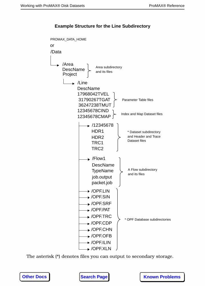
PROMAX_DATA_HOME
/AreaDescNameProject
/LineDescName17968042TVEL31790267TGAT36247238TMUT12345678CIND12345678CMAP
/12345678HDR1HDR2TRC1
/Flow1
TRC2
DescName
job.output
/OPF.LIN/OPF.SIN
A Flow subdirectory
Example Structure for the Line Subdirectory
TypeName
packet.job
and its files
Parameter Table files
Index and Map Dataset files
* Dataset subdirectoryand Header and TraceDataset files
/Dataor
* OPF Database subdirectories
/OPF.SRF/OPF.PAT
/OPF.TRC
/OPF.CDP/OPF.CHN/OPF.OFB
/OPF.ILIN/OPF.XLN
The asterisk (*) denotes files you can output to secondary storage.
Area subdirectoryand its files
Other Docs Known ProblemsSearch Page

Working with ProMAX® Disk Datasets114 ProMAX® Reference
Round Robin Effect
The ProMAX® processing system increments the TRCx andHDRx count by one each time a pair of files is spilled over tothe next available partition, giving each pair a unique UNIXname. If the system has written data to all of the definedsecondary storage partitions during a single output step, andyou need to write more traces, it loops back to the firstoutput partition. The process then continues in a roundrobin fashion, looping through all the available storagepartitions, until it has written the entire dataset to disk.
By default, the system will not write Trace Data to a storagepartition that contains less than eight megabytes of freespace. However, you can use the environment variableMIN_DISK_SPACE to override the default; setMIN_DISK_SPACE to the number of megabytes to reserve.For example, if you set MIN_DISK_SPACE to four, the systemwould write trace data to a disk until only 4 megabytes wereleft.
If you had three storage locations, a typical set of data filesmight look like this:
/advance/data/usertutorials/landexample/78252353CIND /advance/data/usertutorials/landexample/78252353CMAP /advance/data/usertutorials/landexample/78252353/TRC1 /advance/data/usertutorials/landexample/78252353/HDR1 /advance/data/usertutorials/landexample/78252353/TRC4 /advance/data/usertutorials/landexample/78252353/HDR4 /advance/data/usertutorials/landexample/78252353/TRC7 /advance/data/usertutorials/landexample/78252353/HDR7
/advance/data2/usertutorials/landexample/78252353/TRC2 /advance/data2/usertutorials/landexample/78252353/HDR2 /advance/data2/usertutorials/landexample/78252353/TRC5 /advance/data2/usertutorials/landexample/78252353/HDR5 /advance/data2/usertutorials/landexample/78252353/TRC8 /advance/data2/usertutorials/landexample/78252353/HDR8
/advance/data3/usertutorials/landexample/78252353/TRC3 /advance/data3/usertutorials/landexample/78252353/HDR3 /advance/data3/usertutorials/landexample/78252353/TRC6 /advance/data3/usertutorials/landexample/78252353/HDR6
Each sequential pair of TRCx and HDRx files spills to thenext available partition, looping through all partitions asoften as required.
If you specify (set the appropriate parameter in Disk DataOutput) that you want the ProMAX® system to skip the
Other Docs Known ProblemsSearch Page

Working with ProMAX® Disk Datasets115 ProMAX® Reference
primary storage partition, it outputs the CIND and CMAP filesto the primary storage partition, but no TRCx or HDRx fileswill be found there. Each time the dataset spills from onedata partition to the next, the system writes a message intothe job.output file. In addition, the system writes the locationof the additional header and trace files to the index file(...CIND).
What Happens When a Partition is Full
If one of the disk partitions is full, the ProMAX system skipsthat partition and attempts to write to the next listedpartition. In addition, if the primary storage partition is closeto being filled (as specified in the config_file by the primaryoverflow parameter), TRC and HDR files are no longer writtento the primary storage partition, but are automaticallywritten to the next available secondary partition.
If all available disk partitions are full, the ProMAX® job willfail with an appropriate error message. Completely filling theprimary storage partition prevents any other ProMAX® jobsfrom running as no additional flows can be created. Theprimary overflow parameter in the config_file will helpprevent this from occurring.
You can move files from one storage partition to another withno ill affect. For example, you could issue the UNIX command
% mv /advance/data3/usertutorials/landexample/78252353/* \ /advance/data2/usertutorials/landexample/78252353
and the dataset would retain its integrity. The only harm thatcould come from this kind of activity would be if the files werenot placed in any of the 78252353 directories, or if the digitsat the end of the names were changed. Moving files in thismanner is permitted because the remembered locations, asstored in the CIND file, are not explicitly depended on, butare used as an indication of where to look first for those files.If not found in those locations, the search path for the fileswill be taken from the primary and secondary storagepartitions that are listed in the config_file. In the aboveexample you could add /advance/data4 as a secondarystorage partition in the config_file, move all of the ...TRCx and...HDRx files there, and the dataset would retain its integrity.
Note: Active datasets must have all trace and header filesstored in partitions that are mentioned in the config_file.
Other Docs Known ProblemsSearch Page

Working with ProMAX® Disk Datasets116 ProMAX® Reference
Under versions of the ProMAX software prior to release 5.0,secondary storage files were used in a `fill and spill' mode,with no control over the sizes of the individual files written toeach partition. This method of output can still be used. Inorder to achieve this effect, simply set the filesize parameterfor any partition to 2000 (2 gfigabytes). Each partition will befilled to capacity prior to spilling to the next availablepartition.
The round robin file structure for disk datasets alleviatesproblems with secondary storage and archival/retrieval in anumber of ways. The smaller size of the files and the ability tomove them makes it easier to balance disk space utilization.In addition, if an archived dataset needs to be restored, or if aspecific filesystem needs to be removed from a system, thesmaller size datasets are more easily written out to the newsystem configuration.
Note: Refer to the Ordered Parameter Files chapter for adescription of secondary storage and OPF interaction.
Other Docs Known ProblemsSearch Page

Working with ProMAX® Tape Datasets117 ProMAX® Reference
Working with ProMAX® Tape Datasets
A ProMAX® tape dataset is similar to a disk dataset, exceptthat tape datasets incorporate required structures for tapeinput and output, which operate in conjunction with orwithout reference to a tape catalog system.
When you output a dataset to tape, the system writes theTrace Data and Trace Header files, and the original Index andMap files to tape. It writes the original Index and Map files tothe first volume of the dataset, and then writes the mostcurrent Index and Map files to the end of the tape.
The current Index (...CIND) and Map (...CMAP) files reside ondisk in the Dataset subdirectory, providing you withimmediate access to information about the dataset if you areworking with the ProMAX® system. In other words, you donot have to access any tapes because your current Index andMap files are on disk. Additionally, the Index and Map filesprovide all the information necessary to access traces in anon-sequential manner.
Although the Index and Map files reside on disk, copies ofthem are also placed on the end of the tape(s) so that thetape(s) can serve as self-contained units. If the Index andMap files are removed from disk, or never existed, as in thecase where a dataset is shipped to another site, you can readthe tapes without them. However, accessing these datasetsthrough the Index and Map files that reside solely on tapemust be sequential.
Outputting ProMAX® Datasets to Tape
You can output tape datasets by using Tape Data Output.You can input tape datasets using Tape Data Input or TapeData Insert. However, tape datasets and tape devices aremanaged through the Total Tape Solution, or TTS. Refer tothe TTS User Guide for information about this tape system.
Each tape contains a 2048-byte seismic tape header. Thisseismic tape header contains 512 4-byte integers, containinginformation about the dataset, such as its sample interval,trace length, and owner. On the first tape, the seismic tapeheader is followed by a preliminary copy of the Index file,containing whatever information is in the Index file before the
Other Docs Known ProblemsSearch Page

Working with ProMAX® Tape Datasets118 ProMAX® Reference
traces are written (much of this is redundant with the seismictape header). Then, on all tapes, trace data and trace headersare written until either all trace data and headers are written,or until the end of the tape is reached. Following the tracedata and headers on the last reel, a final copy of the Indexand Map file is written. All reels then end with a double end-of-file mark.
Tape Attributes
The following is a list of attributes that are always tracked foreach tape. Some of them may be null for tapes which containnon-seismic data. Other attributes can be added by clientprograms.
Tape Attributes
Attribute Attribute
Dataset description (search key) Next catSeqno in search list
Volume serial number Media type
Status of volume Next catSeqno in dataset
First volume in dataset flag Tape rack slot number
Site number (for multiple sites) Permissions
User ID Group ID
Date created Volume-closed-properly flag
Minimum sequential-trace-number-in-dataset
Maximum sequential-trace-number-in-dataset
Minimum ensemble (primary sortkey) number
Maximum ensemble (primary sortkey) number
Minimum CDP number Maximum CDP number
Minimum SIN (shot indexnumber)
Maximum SIN (shot indexnumber)
Data type (field, unstacked,stacked, archives, etc.)
ProMAX® project
ProMAX® area ProMAX® line/survey
ProMAX® dataset name Primary sort key name
Other Docs Known ProblemsSearch Page