Laboratory Tests of Concrete Beams Reinforced with ... - MDPI
17
materials Article Laboratory Tests of Concrete Beams Reinforced with Recycled Steel Fibres and Steel Bars Malgorzata Paj ˛ ak * and Grzegorz Wandzik Citation: Paj ˛ ak, M.; Wandzik, G. Laboratory Tests of Concrete Beams Reinforced with Recycled Steel Fibres and Steel Bars. Materials 2021, 14, 6752. https://doi.org/10.3390/ ma14226752 Academic Editor: Sara Cattaneo Received: 12 September 2021 Accepted: 5 November 2021 Published: 9 November 2021 Publisher’s Note: MDPI stays neutral with regard to jurisdictional claims in published maps and institutional affil- iations. Copyright: © 2021 by the authors. Licensee MDPI, Basel, Switzerland. This article is an open access article distributed under the terms and conditions of the Creative Commons Attribution (CC BY) license (https:// creativecommons.org/licenses/by/ 4.0/). Department of Structural Engineering, Silesian University of Technology, Akademicka 5, 44-100 Gliwice, Poland; [email protected] * Correspondence: [email protected]; Tel.: +48-32-237-22-88 Abstract: This paper explores the possibility of the partial replacement of the longitudinal rein- forcement in reinforced concrete (RC) beams with recycled steel fibres (RSF). Testing was focused on the contribution of two volume ratios of the RSF—0.5%, 1.0%. Basic compression and flexural tensile tests were performed to evaluate the effectiveness of the fibres following current standards. Additionally, the full-scale beams with and without conventional reinforcement were subjected to four-point bending tests. The results indicate that RSF improved the load-bearing capacity of the RC beams. Cooperation of RSF with the steel bars in carrying loads was proved. Findings from the Digital Image Correlation (DIC) revealed no impact on the cracking pattern of the RC beams. Keywords: recycled steel fibres; flexure; concrete; DIC 1. Introduction It is possible to reduce waste disposal amounts by their re-using in construction building materials. Currently, a huge problem all over the world is the disposal of end- of-life tires. In their reclamation process, two main components are obtained: crumb rubber and steel cord. The rubber component has found a wide range of applications in playgrounds, football pitches and urban pavements [1]. In the literature, attempts can be found to improve the mechanical properties of concrete with crumb rubber. It was found that the addition of rubber particles to concrete caused a pronounced reduction in compressive strength, mainly associated with the lower modulus of elasticity of the rubber in comparison to the concrete. It was shown that an addition of rubber, equal to around 20% of the aggregate content, reduced the compressive strength of concrete approximately by 50% [2,3]. The reduction of the basic characteristic of concrete is usually undesirable. Meanwhile, the second waste tire component consisting of a steel cord (recycled steel fibres) has been found to effectively reduce the brittleness of concrete, which is one of its weaknesses. In general, randomly distributed short fibres improve the tensile strength and energy absorption capacity of concrete. The addition of fibres improve impact, fatigue, as well as fire and frost resistances of cement-based materials. Their effectiveness in the matrix strongly depends on the material (steel, polypropylene, glass, etc.), length and the shape (straight, hooked, crimped, etc.) [4,5]. The most effective are steel fibres, thus why various types of them are commercially available. The recycled steel fibres (RSF) from end-of-life tires differ from manufactured fibres with the stochastic length and diameter, and assorted shapes [6]. This is associated with the process of their reclamation and the type of the tires they are obtained from. Investigations on the impact of the RSF on mechanical properties of concrete have confirmed their usability to reinforce concrete [7–13]. Attempts to establish the contribution of different types of fibres in transferring loads in full-scale beams under flexure has been described in the literature [7,14–18]. The description of the research focused on the hooked-end fibres applied in the RC beams can be found in [15,17,18], for example. Materials 2021, 14, 6752. https://doi.org/10.3390/ma14226752 https://www.mdpi.com/journal/materials
-
Upload
khangminh22 -
Category
Documents
-
view
0 -
download
0
Transcript of Laboratory Tests of Concrete Beams Reinforced with ... - MDPI
materials
Article
Laboratory Tests of Concrete Beams Reinforced with RecycledSteel Fibres and Steel Bars
Małgorzata Pajak * and Grzegorz Wandzik
�����������������
Citation: Pajak, M.; Wandzik, G.
Laboratory Tests of Concrete Beams
Reinforced with Recycled Steel Fibres
and Steel Bars. Materials 2021, 14,
6752. https://doi.org/10.3390/
ma14226752
Academic Editor: Sara Cattaneo
Received: 12 September 2021
Accepted: 5 November 2021
Published: 9 November 2021
Publisher’s Note: MDPI stays neutral
with regard to jurisdictional claims in
published maps and institutional affil-
iations.
Copyright: © 2021 by the authors.
Licensee MDPI, Basel, Switzerland.
This article is an open access article
distributed under the terms and
conditions of the Creative Commons
Attribution (CC BY) license (https://
creativecommons.org/licenses/by/
4.0/).
Department of Structural Engineering, Silesian University of Technology, Akademicka 5, 44-100 Gliwice, Poland;[email protected]* Correspondence: [email protected]; Tel.: +48-32-237-22-88
Abstract: This paper explores the possibility of the partial replacement of the longitudinal rein-forcement in reinforced concrete (RC) beams with recycled steel fibres (RSF). Testing was focusedon the contribution of two volume ratios of the RSF—0.5%, 1.0%. Basic compression and flexuraltensile tests were performed to evaluate the effectiveness of the fibres following current standards.Additionally, the full-scale beams with and without conventional reinforcement were subjected tofour-point bending tests. The results indicate that RSF improved the load-bearing capacity of theRC beams. Cooperation of RSF with the steel bars in carrying loads was proved. Findings from theDigital Image Correlation (DIC) revealed no impact on the cracking pattern of the RC beams.
Keywords: recycled steel fibres; flexure; concrete; DIC
1. Introduction
It is possible to reduce waste disposal amounts by their re-using in constructionbuilding materials. Currently, a huge problem all over the world is the disposal of end-of-life tires. In their reclamation process, two main components are obtained: crumbrubber and steel cord. The rubber component has found a wide range of applications inplaygrounds, football pitches and urban pavements [1]. In the literature, attempts canbe found to improve the mechanical properties of concrete with crumb rubber. It wasfound that the addition of rubber particles to concrete caused a pronounced reduction incompressive strength, mainly associated with the lower modulus of elasticity of the rubberin comparison to the concrete. It was shown that an addition of rubber, equal to around20% of the aggregate content, reduced the compressive strength of concrete approximatelyby 50% [2,3]. The reduction of the basic characteristic of concrete is usually undesirable.Meanwhile, the second waste tire component consisting of a steel cord (recycled steelfibres) has been found to effectively reduce the brittleness of concrete, which is one ofits weaknesses.
In general, randomly distributed short fibres improve the tensile strength and energyabsorption capacity of concrete. The addition of fibres improve impact, fatigue, as wellas fire and frost resistances of cement-based materials. Their effectiveness in the matrixstrongly depends on the material (steel, polypropylene, glass, etc.), length and the shape(straight, hooked, crimped, etc.) [4,5]. The most effective are steel fibres, thus why varioustypes of them are commercially available. The recycled steel fibres (RSF) from end-of-lifetires differ from manufactured fibres with the stochastic length and diameter, and assortedshapes [6]. This is associated with the process of their reclamation and the type of the tiresthey are obtained from. Investigations on the impact of the RSF on mechanical propertiesof concrete have confirmed their usability to reinforce concrete [7–13].
Attempts to establish the contribution of different types of fibres in transferring loadsin full-scale beams under flexure has been described in the literature [7,14–18].
The description of the research focused on the hooked-end fibres applied in the RCbeams can be found in [15,17,18], for example.
Materials 2021, 14, 6752. https://doi.org/10.3390/ma14226752 https://www.mdpi.com/journal/materials
Materials 2021, 14, 6752 2 of 17
RC beams with a span of 2.1 m made of concrete containing 40 kg/m3 and 60 kg/m3
of fibres were investigated in [15]. According to this study, in the beams with shearreinforcement and tensile reinforcement (ρ = 0.70%) the addition of fibres almost didnot modify the mechanical response of the structural members. On the other hand, it isreported that in the beams where no stirrups were applied, the fibres lead to an increase ofthe shear strength.
Similar conclusions were found in [17], where the addition of hooked steel fibres(1%, 1.5%, 2%) did not lead to pronounced improvement of the load-bearing capacity inflexure. However, in the same experiments, the reduction in deflections at lower loads werereported. Concurrently, in [18] where the beams, with the span of 1.2 m and a reinforcementratio ρ = 0.3–0.7%, were subjected to bending and the fibres led to a pronounced increasein load-bearing capacity. The cited publications lead to quite an obvious conclusion thatweakly reinforced elements can be made more efficient with fibre reinforcement.
The comparable beam studies [7,14] were carried out for fibres derived from recycling.The basic difference in these types of fibres is related to their size and shape. Unlikemanufactured fibres for dedicated use in concrete may have a shape depending on theiracquisition and not fit as well as those manufactured. Several conclusions on RSF duplicatethe conclusions formulated for those factory-produced. For example, the impact of theRSF, with volume ratios of 0.5% and 1.0%, on the behaviour of beams with the span equalto 3.42 m were investigated in [7]. Based on these studies, the positive influence of theRSF on the cracking phenomenon was indicating. The reduction of cracks width and theirspacing was pointed out. Furthermore, it is confirmed that RSF are most effective in beamswith lower reinforcement ratio. Additionally, the improvement of the load capacity, next tothe reduction of the deflection and crack propagation was also mentioned in [14]. In thatinvestigation the lathe fibres were applied with the volume ratio ranged from 0.5% to 2%to the RC beams with the span of 2.1 m.
Several attempts for substituting manufactured construction materials, used for re-inforcing concrete beams (steel bars or fibres), with different types of natural or wastematerials have been reported. The use of the bamboo fibres [19] or fibres from wastebottles [20] can be good examples. Their effectiveness still requires more investigation. Theother example can also be the research providing that polypropylene discrete macro-fibresimproved the ductility of beams reinforced with Glass Fibre Reinforced Polymer bars [16].In this study, more cracks were noted distributed along the beams with fibres.
The investigation described in the present paper is focused on finding the contributionof recycled tire fibres on the bending behaviour of beams. To achieve this purpose, materialand full-scale beam tests with concrete reinforced with conventional steel bars and twoamounts of RSF were performed. Reference RC beams with no fibres added were also tested.Beams with small amounts of conventional reinforcement was chosen for full-scale tests,because they are shown to have a more pronounced influence of fibres addition [15,17].
2. Experimental Program2.1. Materials
The influence of RSF on the mechanical properties of the concrete matrix was studied.To achieve this, CEM III/A 42.5N—LH/HSR/NA cement produced by Górazdze Polandwas used. The superplasticizer MasterSure 1200 produced by Master Builders SolutionsPoland. (0.85% by mass of cement) was applied to maintain the concrete consistency. Theexact composition of the concrete is presented in Table 1. The properties of fibres from theend-of-life tires produced by Gumeco Poland are summarized in Table 2. The fibres with astochastic length and curved shape are shown in Figure 1. The same type of fibres wereused by authors in previous investigations [11–13]. In the present investigation, the RSFwere added to concrete in two amounts: 39.25 kg/m3 and 78.5 kg/m3 to create the recycledsteel fibre reinforced concrete (abbreviation used in the manuscript—FRC). According tothe above-mentioned works, these amounts guarantee mixes in which fibres can be used

Materials 2021, 14, 6752 3 of 17
to partially replace conventional reinforcement. The accompanying tests of plain concretewith no fibres were also performed.
Table 1. Composition of concrete mix.
Mix Cement[kg/m3]
Sand[kg/m3]
CoarseAggregate
[kg/m3]
SilicaFume
[kg/m3]Superplasticizer Water
[L/m3]
Fibres
[kg/m3]VolumeRatio Vf
C-0300 840 892 80 2.55 165
0 0FRC-0.5 39.25 0.5%FRC-1.0 78.5 1.0%
Table 2. RSF properties.
Length [mm] Diameter [mm] TensileStrength [MPa]
Aspect Ratio(Length/Diameter)
LongitudinalShape
~2–50 0.15 ± 5% ≥2850 13–200 irregular(curved, twisted)
Figure 1. Fibres from the end-of-life tires used in the investigation.
The slump flow tests of fresh mixes were performed according to PN-EN 12350-5 [21].The addition of the RSF reduced the slump flow diameter (Table 3).
Table 3. Slump flow.
Mix Fibres Volume Ratio Vf Slump Flow [mm]
C-0 0 495FRC-0.5 0.5% 440FRC-1.0 1.0% 375
2.2. Specimens and Testing Methods
All specimens were cast in one concreting. The concrete was mixed in the concretemixer and the fibres were added to it. The concrete was vibrated after being placed inthe formwork. After one day the specimens were demoulded and cured in water at atemperature of 20 ◦C till the day of the tests.
2.2.1. Compression and Flexural Tests
The compressive strength and modulus of elasticity were determined on cylindricalsamples with a diameter of 150 mm and height of 300 mm. Six cylinders were preparedfor each mix. The compression tests were carried out in a 3000 kN hydraulic testing
Materials 2021, 14, 6752 4 of 17
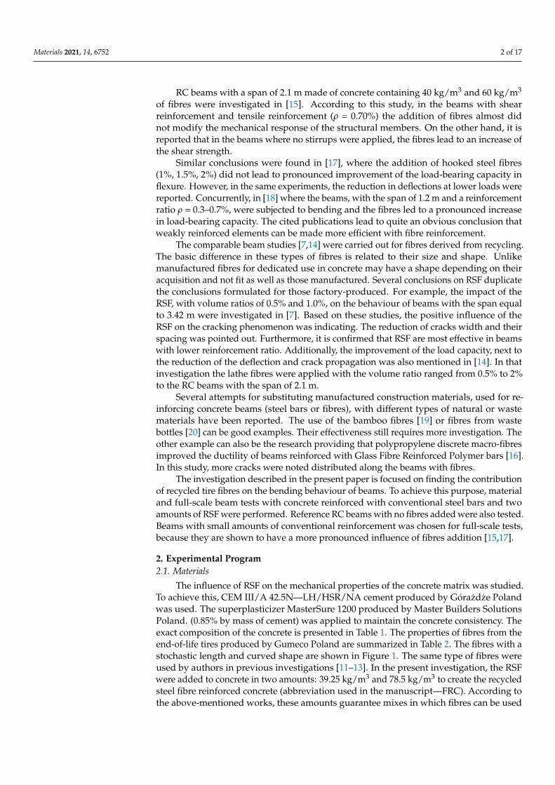
machine according to EN 12390-3 [22]. The tests were performed applying a constant rateof displacement equal to 1 mm/min. The strains in the plain concrete specimens (mix C-0)were measured using 3 strain gauges. In the case of FRC, the strains were measured usingthe LVDTs mounted on the steel frame (Figure 2). For the FRC, the compression tests wereperformed with a constant rate of displacement to obtain the stress-strain curve after theachieving of the maximum load. This is a key, as the real influence of the fibres on thebehaviour of the brittle matrix is observed in the post-peak regime of the stress-strain curvebecause the fibres bridge the cracks.
Figure 2. The compression test of the FRC specimen.
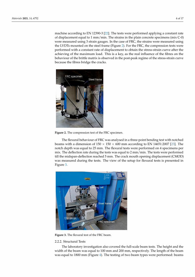
The flexural behaviour of FRC was analysed in a three-point bending test with notchedbeams with a dimension of 150 × 150 × 600 mm according to EN 14651:2007 [23]. Thenotch depth was equal to 25 mm. The flexural tests were performed on 4 specimens permix. The deflection rate during the tests was equal to 2 mm/min. The tests were performedtill the midspan-deflection reached 5 mm. The crack mouth opening displacement (CMOD)was measured during the tests. The view of the setup for flexural tests is presented inFigure 3.
Figure 3. The flexural test of the FRC beam.
2.2.2. Structural Tests
The laboratory investigation also covered the full-scale beam tests. The height and thewidth of the beam was equal to 100 mm and 200 mm, respectively. The length of the beamwas equal to 1800 mm (Figure 4). The testing of two beam types were performed: beams

Materials 2021, 14, 6752 5 of 17
reinforced only with the recycled steel fibres (series FRC) and beams with both longitudinaland RSF reinforcement (series FRC-RC). The research program is presented in the Table 4.
Figure 4. View of the RC/FRC-RC beam—four-points test layout.
Table 4. Research program.
Mix
FibresReinforcement—Fibres Volume
Ratio Vf
View of the BeamLongitudinal
Reinforcement—Bars
ShearReinforcement—
Stirrups
Number ofBeams
FRC-0.5 0.5% - - 3FRC-1.0 1.0% - - 3
RC-0 0 2 ø 6 mm ø 4 mm every 70mm 3
FRC-RC-0.5 0.5% 2 ø 6 mm ø 4 mm every 70mm 3
FRC-RC-1.0 1.0% 2 ø 6 mm ø 4 mm every 70mm 3
The RC beams were reinforced with two bottom longitudinal bars with a diameter of6 mm and partially reinforced with upper longitudinal bars with a diameter of 6 mm at thesupport zones. The tensile reinforcement ratio was equal to 0.32%. The concrete cover wasequal to 15 mm. The stirrups were only added in the shear zone of the beam, protecting itagainst shear failure. The shear reinforcement consists of stirrups with a diameter of 4 mmspaced every 70 mm (Figure 4). The strain gauges were mounted on the bottom steel barsat the midpoint of the beam. The view of the beams in the multi-station cast before andafter casting is presented in Figure 5.

Materials 2021, 14, 6752 6 of 17
Figure 5. View of the RC beams before and after casting.
The beams with an overall length of 1.8 m were subjected to the four-point bendingtests (Figure 6). The span of the beam was equal to l = 1.6 m. The load was applied withthe constant rate of displacement equal to 1 mm/min till the failure of the specimen.
Figure 6. FRC-RC beams during the four-point test: (a) front view; (b) back view.
During the tests, the strains of the longitudinal bottom bars were measured. The strainof the beam surface was measured in the compression and tension zones. The strain gaugeswere glued to the beam—its arrangement is schematically presented in Figure 4. In the RCbeams, the strain gauges were also placed on the side surface at the depth correspondingto the location of the longitudinal bars. The deflection of the beam in the middle and underthe points where the load was applied were measured using LVDTs. The support positionswere also controlled by the LVDTs.
The deformation of the almost whole front surface of the beam was monitored by theDigital Image Correlation (DIC) system—Aramis.
Materials 2021, 14, 6752 7 of 17
3. Results of Empirical Investigation3.1. The Compression and Flexural Material Tests
The results of the compression tests are presented in Table 5. The coefficient ofvariation (in percent) is shown in the parentheses. The addition of fibres had no noticeableeffect on the compressive strength and the corresponding strain of the concrete. It confirmsthe expectations that the fibres slightly affect the compressive stress transfer mechanism.All average strain-stress curves are almost identical in the ascending part. Some influenceof the fibres is visible on the post-peak part of the stress-strain curve—see Figure 7. TheFRC exhibited the ability to carry the loads after achieving the peak point. The slope of thedescending part of the curve was dependent on the fibre content, where an increase of thenumber of fibres was found to lower the softening rate.
Table 5. Results from the compression tests.
Mix
FibresReinforcement—
Fibres Volume RatioVf [%]
CompressiveStrength [MPa]
StrainCorresponding to
CompressiveStrength [10−3]
C-0 0 31.36 (4) 1.9 (7)FRC-0.5 0.5 31.76 (2) 2.1 (5)FRC-1.0 1.0 30.82 (5) 1.9 (19)
Figure 7. The stress-strain curves from the compression tests.
Fibre efficiency was determined in terms of their influence on the mechanical tensileproperties of concrete. For this purpose, the FRC was tested in the three-point bendingtests on notched beams [23,24]. The relationships between the tensile stress and CMODestablished in these tests are shown for both types of FRC in the diagrams (Figures 8 and 9)prepared for each test, as well as their average values.

Materials 2021, 14, 6752 8 of 17
Figure 8. Stress-CMOD curves from flexural tests on FRC-0.5.
Figure 9. Stress-CMOD curves from flexural tests on FRC-1.0.
The parameters obtained from the tests are the flexural tensile strength at the limitof proportionality (fL) and the residual flexural tensile strengths (fR,i) at the four valuesof crack mouth opening displacement (CMOD): 0.5 mm, 1.5 mm, 2.5 mm and 3.5 mm.All these values are presented in Figures 8 and 9. A description of the method appliedfor stress calculation can be found in another author’s publication [11]. All basic tensileproperties are summarized in Table 6.
Table 6. Three-point flexural tensile tests—mean values.
MixFibres
Reinforcement—Fibres Volume
Ratio Vf [%]
Limit ofProportion-
ality[MPa]
Residual Flexural Tensile Strength [MPa] fR.3/fR.1 fR.1/fL
f L f R.1 f R.2 f R.3 f R.4
C-0 0 2.95 - - - - - -
FRC-0.5 0.5 3.26 2.02 > 1.5 1.86 1.43 1.18 > 1.0 0.71 >0.5
0.62 >0.4
FRC-1.0 1.0 3.42 2.99 > 1.5 2.7 2.43 1.71 > 1.0 0.81 >0.5
0.87 >0.4

Materials 2021, 14, 6752 9 of 17
To determine the possibility of the partial replacement of conventional reinforcementwith fibres, the Model Code 2010 [25] proposes an analysis of fL together with fR.1 and fR.3according to Equation (1):
fR.1/fL > 0.4; fR.3 / fR.1 > 0.5 (1)
Furthermore, according to Model Code 2010 [25], the constitutive law for FRC undertension can be derived using the parameters mentioned above. On the other hand, thestandard EN 14889-1:2006 [26] specifies the minimum residual strength values that have tobe achieved to consider the fibres as effective (2):
fR.1 > 1.5 MPa; fR.4 > 1.0 MPa (2)
A simple comparison of the diagrams in Figures 8 and 9 shows that an increase inthe fibre content (in the tested range) clearly improves the strength properties of concretein tension. At the same time, the requirements expressed in formulas (1) and (2) are met(see Table 6). This indicates that according to Model Code 2010 [25] the tested fibres arepotentially able to partially replace the conventional reinforcement.
3.2. The Full-Scale Beam Tests3.2.1. The Beams Reinforced Only with the RSF
The load-deflection curves obtained in the flexural tests (described in the chapter 2.2.2)performed on the full-scale beams reinforced only with the recycled steel fibres are presentedin Figures 10 and 11 or FRC-0.5 and FRC-1.0, respectively. The tests were performed till themid-span deflection reached the value of l/200 = 8 mm.
Figure 10. Load–deflection curves from flexural tests on FRC-0.5.
Figure 11. Load–deflection curves from flexural tests on FRC-1.0.

Materials 2021, 14, 6752 10 of 17
Direct comparison of the average curves presented in Figures 10 and 11 is also presentedin the Figure 12. It can be concluded that the load-bearing capacity of both types of beams wascomparable. The slightly higher value for the maximum load was noted for the beams with thehigher amount of the fibres (Table 7). The mid-span deflection corresponding to the maximumload was two times bigger for FRC-1.0 than for FRC-0.5 (Table 7). However, in the case ofFRC-1.0, a higher scatter of results was observed (Figure 11). The influence of both amountsof fibres was noted in the post-peak regime of the load-deflection curve. Generally, in the caseof samples reinforced with RSF (FRC-0.5), a significant softening after reaching the peak loadwas noted. The higher number of fibres (FRC-1.0) caused some hardening before the maximumload capacity was achieved and mild softening in comparison to FRC-0.5. FRC beams witha higher fibre content were found to withstand the load carrying capacity much longer. Thisis clearly related to FRC’s ability to retain tensile stress after cracking. For example, when thedeflection reached the value of 2 mm, the load applied to the FRC-0.5 beam was 2.0 kN, whilefor FRC-1.0 it was more than twice as much and amounted to 5.3 kN. This confirms that anincrease in the number of fibres, leads to an increase of efficiency in the post-peak phase. Thedetailed results of the structural tests are summarized in Table 7.
Figure 12. Comparison of the load-deflection curves from flexural tests on FRC series.
Table 7. Results from the flexural tests on beams.
Mix Maximum Total Load [kN] Bending Moment[kNm]
Deflection Corresponding tothe εc = 0.2‰
FRC-0.5 7.09 (1) 1.95 0.3FRC-1.0 7.26 (1) 2.00 0.72
RC 22.93 (5) 6.31 3.61FRC-RC-0.5 24.84 (2) 6.83 4.57FRC-RC-1.0 27.77 (1) 7.64 4.64
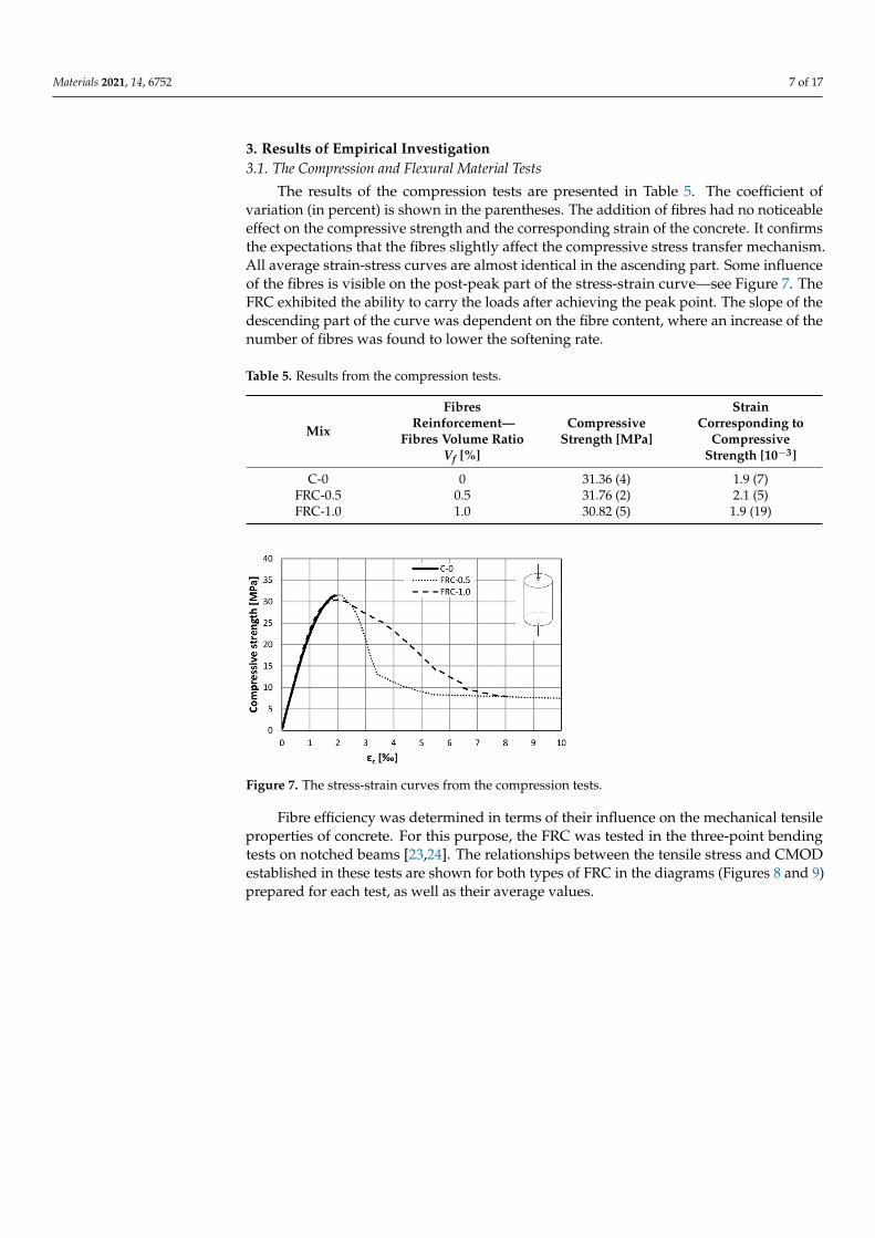
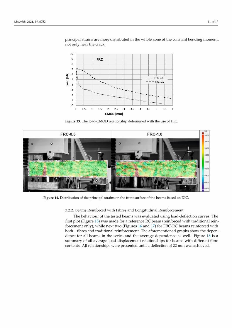
The course of the tests was monitored with the use of DIC which determined thedevelopment of cracks in beams. The CMOD presented in Figure 13 represents the evolu-tion of the main cracks in the beams. They are the average of CMOD values obtained forthree FRC-1.0 beams and one for the FRC-0.5 beam. In two other FRC-0.5 beams the maincrack appeared in the zone not monitored by the DIC. Please note that because of technicallimitations only the half of the beam could be observed. The results confirmed the bettercapacity of the FRC-1.0 beams to withstand loads than the FRC-0.5. The comparison of theviews of the front surface of the selected beams monitored by the DIC are presented inFigure 14. The distribution of the principal strains at the moment when the CMOD is equalto around 0.2 mm is presented in Figure 14. In both beams only one crack was formed tillthe failure of the beam. However, it can be seen that for 0.5% of the fibres, the principaltensile strains are localised closer to the crack, while when more fibres are used (FRC-1.0)
Materials 2021, 14, 6752 11 of 17
principal strains are more distributed in the whole zone of the constant bending moment,not only near the crack.
Figure 13. The load-CMOD relationship determined with the use of DIC.
Figure 14. Distribution of the principal strains on the front surface of the beams based on DIC.
3.2.2. Beams Reinforced with Fibres and Longitudinal Reinforcement
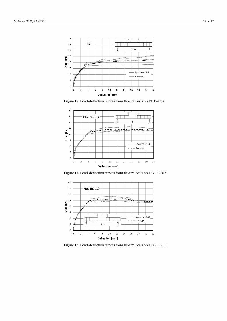
The behaviour of the tested beams was evaluated using load-deflection curves. Thefirst plot (Figure 15) was made for a reference RC beam (reinforced with traditional rein-forcement only), while next two (Figures 16 and 17) for FRC-RC beams reinforced withboth—fibres and traditional reinforcement. The aforementioned graphs show the depen-dence for all beams in the series and the average dependence as well. Figure 18 is asummary of all average load-displacement relationships for beams with different fibrecontents. All relationships were presented until a deflection of 22 mm was achieved.
Materials 2021, 14, 6752 12 of 17
Figure 15. Load-deflection curves from flexural tests on RC beams.
Figure 16. Load-deflection curves from flexural tests on FRC-RC-0.5.
Figure 17. Load-deflection curves from flexural tests on FRC-RC-1.0.

Materials 2021, 14, 6752 13 of 17
Figure 18. Comparison of the load-deflection curves from flexural tests on FRC-RC series.
Generally, the course of the load-deflection curves for all three beams in each serieshave a similar shape. In each case, three sections can be distinguished. The boundariesbetween them are the result of the first cracks appearing and the reinforcing steel yielding.
Along the first segment (until the deflection of about 0.4 mm is achieved), the analyseddependence is the same for all 3 series. In this range, the beams work elastically and thereis no pronounced influence of the fibres. It begins to be visible after exceeding the loadof about 8 kN (corresponding to the appearance of the first cracks). The load-deflectioncurve was flattened above this load level, which led to the more pronounced increase ofdeflections in all cases. Nevertheless, this was seen to be faster with the lower fibre content.For a force of 16 kN, the average deflections were: 2.77 mm (RC), 2.38 mm (FRC-RC-0.5)and 1.89 mm (FRC-RC-1.0).
The merit of the use of the randomly distributed fibre reinforcement is resulted in anincrease in the load-bearing capacity. For the FRC-RC-1.0 series the maximum load was 20%higher than for the RC series and reached 27.77 kN (compared to 22.93 kN for RC beams).
However, analysing the whole course of the load-deflection curve it can be noted thatthe benefit of the fibres decreased with increasing deflection. This led to the increasinglygreater plastic deformation of the reinforcing steel bars and the progressive opening ofcracks which decreased in the tensile transmission by fibres. This is manifested in the slowre-approach of the three curves in Figure 18 for large deflections. Thus, it can be concludedthat the benefit of the fibres is reduced at very small and very large beam deflections(see Figures 12 and 13). The maximum loads (averaged for all beams in series) and thecorresponding deflections can be found in Table 7.
The strain gauges placed on the bottom bars measured steel elongation for the durationof the test. Figure 19 shows the variability of the average steel strain (average of two barsand three beams in the series) with increased loading. The course of the curves showsthat the fibres begin to actively work when the strain in the steel reaches 0.2‰, whichcorresponds to the tensile strength of concrete.

Materials 2021, 14, 6752 14 of 17
Figure 19. Strain in bottom steel reinforcement in RC/FRC-RC beams.
After exceeding a load of 8 kN (strain about 0.2‰), the rate of strain in steel became muchfaster. This is a typical effect for reinforced concrete elements resulting from the loss of theability to transmit tensile stresses by concrete in the cross-section coming through the crack.Above this load level, a clear differentiation in the functioning of the beams depending on thefibre content can be observed. When analysing any force level after cracking, it can be seen thatin the elements made of plain concrete, the steel strains are significantly greater. The need toensure an equilibrium of forces in the cross-section together with the lower steel strains andstresses clearly indicate the participation of fibres in the transmission of tensile forces in thecross-section. For example, analysing the strains (Figure 19) it can be concluded that for theload F = 15 kN the tensile force transmitted by the reinforcement in the FRC-RC-1.0 beam isonly half that for the element without fibres (RC).
It is also worth paying attention to the course of the graph immediately after cracking(in the force range of 8–10 kN). In an element without fibres, the increase in steel strainis rapid and occurs at a constant load value. This shows the high speed of the crackingprocess in this type of element and the rate with which unreinforced concrete loses itstensile capacity. In the tests, this strain increment took place in a very short time. Thebehaviour of the elements with fibres is slightly different. After the crack is formed, thesteel elongates gradually and is accompanied by a slight increase in force (greater forelements with higher fibre content). Based on this, it is possible to reduce the abruptness ofthe change in the strain state in the cross-section.
The diagram in Figure 19 shows the deformation of steel bars only in the elastic phase.After rapid change in steel strain, in range from 0.2‰ to 1‰ in RC elements, a furtherincrease in load is associated with a gradual elongation. From a strain of about 1‰, allthree lines (representing different fibres content) are almost parallel. This indicates theconstant cooperation of the RSF with the conventional bars in this domain.
During the tests, more than half of the side surface of the beams was continuouslymonitored by the DIC system. The distribution of the principal strains in all 9 reinforcedbeams is presented in Figure 20. The images shown in Figure 20 correspond to the loadwhen the steel strain reached the value of 0.2‰, when crack formation in each beambecome visible. The comparison of these images shows that the presence of the fibreshas no significant effect on the number of major cracks and the distance between them.Nevertheless, the increase of fibre volume ratio resulted in the distribution of the strainson the side surface of the beam to change. The tensile zones also appeared in the middlepart of the beams reinforced with the fibres. It demonstrates that, due to the fibres, thewhole beam takes part in carrying the loads. In the next steps the opening of one crack wasobserved in all the beams. The view of all the beams after the test is presented in Figure 21.

Materials 2021, 14, 6752 15 of 17
Figure 20. Distribution of the principal strain on the front surface of the RC/FRC–RC beams based on DIC.
Figure 21. The view of the beams after the test.
4. Conclusions
The volume ratios of 0.5% and 1.0% of recycled steel fibres improved the tensileparameters of the concrete matrix what was proved based on the flexural tensile tests onnotched beams. The residual flexural tensile strength values obtained indicated that theRSF can be used to partially replace conventional reinforcement. The increase of flexural

Materials 2021, 14, 6752 16 of 17
strengths was proportional to the increase of the number of fibres. No apparent influenceof the fibres on the compressive strength of concrete was noted.
This study carried out using full-scale beams reinforced only with the recycled steelfibres or their combination with longitudinal reinforcement indicate that:
• The addition of the fibres resulted in an increase of the load-bearing capacity of the RCbeams. The maximum load went from 22.93 kN on average for RC beams to 27.77 kNon average for the FRC-RC-1.0 beams This demonstrates the efficiency of the fibreseven at the ultimate limit state. For the same load, the strains in steel bars were lowerin the beams where RSF were applied;
• In the beams with a 1.6 m span the application of RSF had no apparent influence onthe distance between the cracks and their number;
• The beams reinforced only with the RSF were able to carry the loads after cracking.The maximum load recorded was equal to around 7 kN. Only one crack was noted inthe brittle failure of all FRC beams.
Author Contributions: Conceptualization, M.P. and G.W.; methodology, M.P. and G.W.; software,M.P. and G.W. validation, M.P. and G.W.; formal analysis, M.P. and G.W.; investigation, M.P. and G.W.;resources, M.P. and G.W.; data curation, M.P. and G.W.; writing—original draft preparation, M.P.and G.W.; writing—review and editing, M.P. and G.W.; visualization, M.P. and G.W.; supervision,M.P. and G.W.; project administration, M.P. and G.W.; funding acquisition, M.P. and G.W. All authorshave read and agreed to the published version of the manuscript.
Funding: This research was funded by Polish Ministry Education and Science BK-235/RB6/2021and scholarship founded by Rector of the Silesian University of Technology 07/SFW18/003-05/2019.
Institutional Review Board Statement: Not applicable.
Informed Consent Statement: Not applicable.
Data Availability Statement: The data presented in this study are available on request from thecorresponding author.
Conflicts of Interest: The authors declare no conflict of interest.
References1. Celeiro, M.; Armada, D.; Dagnac, T.; de Boer, J.; Llompart, M. Hazardous compounds in recreational and urban recycled surfaces
made from crumb rubber. Compliance with current regulation and future perspectives. Sci. Total Environ. 2021, 755, 142566.[CrossRef] [PubMed]
2. Eisa, A.S.; Elshazli, M.T.; Nawar, M.T. Experimental investigation on the effect of using crumb rubber and steel fibers on thestructural behavior of reinforced concrete beams. Constr. Build. Mater. 2020, 252, 119078. [CrossRef]
3. Strukar, K.; Šipoš, T.K.; Dokšanovic, T.; Rodrigues, H. Experimental Study of Rubberized Concrete Stress-Strain Behavior forImproving Constitutive Models. Materials 2018, 11, 2245. [CrossRef] [PubMed]
4. Brandt, A.M. Fibre reinforced cement-based (FRC) composites after over 40 years of development in building and civil engineering.Compos. Struct. 2008, 86, 3–9. [CrossRef]
5. Holschemacher, K.; Mueller, T.; Ribakov, Y. Effect of steel fibres on mechanical properties of high-strength concrete. Mater. Des.2010, 31, 2604–2615. [CrossRef]
6. Domski, J.; Katzer, J.; Zakrzewski, M.; Ponikiewski, T. Comparison of the mechanical characteristics of engineered and wastesteel fiber used as reinforcement for concrete. J. Clean. Prod. 2017, 158, 18–28. [CrossRef]
7. Groli, G.; Caldentey, A.P.; Soto, A.G. Cracking performance of SCC reinforced with recycled fibres-an experimental study. Struct.Concr. 2014, 15, 136–153. [CrossRef]
8. Mastali, M.; Dalvand, A.; Sattarifard, A.; Abdollahnejad, Z.; Illikainen, M. Characterization and optimization of hardenedproperties of self-consolidating concrete incorporating recycled steel, industrial steel, polypropylene and hybrid fibers. Compos.Part Eng. 2018, 151, 186–200. [CrossRef]
9. Martinelli, E.; Caggiano, A.; Xargay, H. An experimental study on the post-cracking behaviour of Hybrid Industrial/RecycledSteel Fibre-Reinforced Concrete. Constr. Build. Mater. 2015, 94, 290–298. [CrossRef]
10. Centonze, G.; Leone, M.; Aiello, M. Steel fibers from waste tires as reinforcement in concrete: A mechanical characterization.Constr. Build. Mater. 2012, 36, 46–57. [CrossRef]
11. Pajak, M. Concrete reinforced with various amounts of steel fibers reclaimed from end-of-life tires. In Proceedings of the MATECWeb Conference, Sibiu, Romania, 5–7 June 2019; p. 262. [CrossRef]
12. Pajak, M. Research on concrete reinforced with fibers from end-of-life tires. Inzynieria Bud. 2018, 74, 267–270.

Materials 2021, 14, 6752 17 of 17
13. Pajak, M.; Krystek, M.; Zakrzewski, M.; Domski, J. Laboratory Investigation and Numerical Modelling of Concrete Reinforcedwith Recycled Steel Fibers. Materials 2021, 14, 1828. [CrossRef] [PubMed]
14. El-Sayed, T.A. Flexural behavior of RC beams containing recycled industrial wastes as steel fibers. Constr. Build. Mater. 2019, 212,27–38. [CrossRef]
15. Folino, P.; Ripani, M.; Xargay, H.; Rocca, N. Comprehensive analysis of Fiber Reinforced Concrete beams with conventionalreinforcement. Eng. Struct. 2020, 202, 109862. [CrossRef]
16. Junaid, M.T.; Elbana, A.; Altoubat, S.; Al-Sadoon, Z. Experimental study on the effect of matrix on the flexural behavior of beamsreinforced with Glass Fiber Reinforced Polymer (GFRP) bars. Compos. Struct. 2019, 222, 110930. [CrossRef]
17. Küsel, F.; Kearsley, E. Effect of steel fibres in combination with different reinforcing ratios on the performance of continuousbeams. Constr. Build. Mater. 2019, 227, 116553. [CrossRef]
18. Cardoso, D.C.; Pereira, G.B.; Silva, F.A.; Filho, J.J.S.; Pereira, E.V. Influence of steel fibers on the flexural behavior of RC beamswith low reinforcing ratios: Analytical and experimental investigation. Compos. Struct. 2019, 222, 110926. [CrossRef]
19. Elbehiry, A.; Elnawawy, O.; Kassem, M.; Zaher, A.; Uddin, N.; Mostafa, M. Performance of concrete beams reinforced usingbanana fiber bars. Case Stud. Constr. Mater. 2020, 13, e00361. [CrossRef]
20. Meza, A.; Siddique, S. Effect of aspect ratio and dosage on the flexural response of FRC with recycled fiber. Constr. Build. Mater.2019, 213, 286–291. [CrossRef]
21. European Committee for Standartization. European Committee for Standartization EN 12350-5 Testing Fresh Concrete-Part 5: FlowTable Test. European Standard; European Committee for Standartization: Brussels, Belgium, 2009.
22. British Standards Institution. British Standards Institution BS EN 12390-3: 2009. Test. Hardened Concrete Part 3 Compressive StrengthTest Specimens; British Standards Institution: London, UK, 2009.
23. European Committee for Standartization. EN 14651. In Test Method for Metallic Fibered Concrete-Measuring the Flexural TensileStrength (Limit or Proportionality (LOP), Residual); European Committee for Standartization: Brussels, Belgium, 2005.
24. Taheri, M.; Barros, J.A.; Salehian, H. Integrated approach for the prediction of crack width and spacing in flexural FRC memberswith hybrid reinforcement. Eng. Struct. 2020, 209, 110208. [CrossRef]
25. Walvaren, J. Model Code 2010, final drafts. FIB Bull. 2012, 1, 1–2.26. European Committee for Standartization. EN 14889-1. In Fibres for Concrete-Part 1: Steel fibres-Definitions, Specifications and
Conformity; European Committee for Standartization: Brussels, Belgium, 2006.