Design Guide for Masonry Reinforced by Bond Beams and ...
20
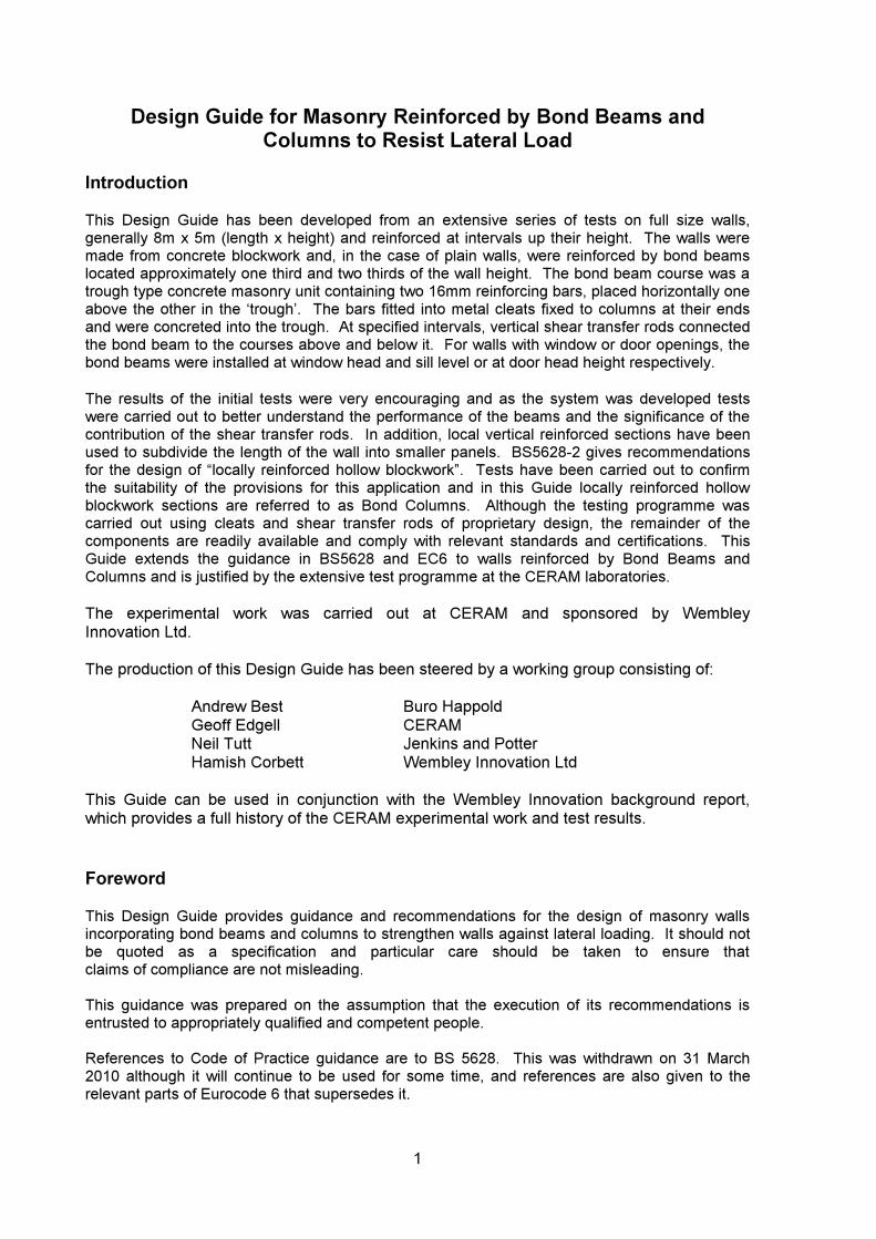
Design Guide for Masonry Reinforced by Bond Beams and Columns to Resist Lateral Load
-
Upload
khangminh22 -
Category
Documents
-
view
0 -
download
0
Transcript of Design Guide for Masonry Reinforced by Bond Beams and ...

Design Guide for Masonry Reinforced by
Bond Beams andColumns to Resist
Lateral Load
Design Guide for Masonry Reinforced by Bond Beams and Columns to Resist Lateral Load
Introduction
This Design Guide has been developed from an extensive series of tests on full size walls, generally 8m x 5m (length x height) and reinforced at intervals up their height. The walls weremade from concrete blockwork and, in the case of plain walls, were reinforced by bond beams located approximately one third and two thirds of the wall height. The bond beam course was a trough type concrete masonry unit containing two 16mm reinforcing bars, placed horizontally oneabove the other in the ‘trough’. The bars fitted into metal cleats fixed to columns at their endsand were concreted into the trough. At specified intervals, vertical shear transfer rods connectedthe bond beam to the courses above and below it. For walls with window or door openings, the bond beams were installed at window head and sill level or at door head height respectively.
The results of the initial tests were very encouraging and as the system was developed tests were carried out to better understand the performance of the beams and the significance of thecontribution of the shear transfer rods. In addition, local vertical reinforced sections have beenused to subdivide the length of the wall into smaller panels. BS5628-2 gives recommendationsfor the design of “locally reinforced hollow blockwork”. Tests have been carried out to confirm the suitability of the provisions for this application and in this Guide locally reinforced hollow blockwork sections are referred to as Bond Columns. Although the testing programme wascarried out using cleats and shear transfer rods of proprietary design, the remainder of thecomponents are readily available and comply with relevant standards and certifications. This Guide extends the guidance in BS5628 and EC6 to walls reinforced by Bond Beams andColumns and is justified by the extensive test programme at the CERAM laboratories.
The experimental work was carried out at CERAM and sponsored by Wembley Innovation Ltd.
The production of this Design Guide has been steered by a working group consisting of:
Andrew Best Buro Happold Geoff Edgell CERAM Neil Tutt Jenkins and Potter Hamish Corbett Wembley Innovation Ltd
This Guide can be used in conjunction with the Wembley Innovation background report, which provides a full history of the CERAM experimental work and test results.
Foreword
This Design Guide provides guidance and recommendations for the design of masonry walls incorporating bond beams and columns to strengthen walls against lateral loading. It should notbe quoted as a specification and particular care should be taken to ensure thatclaims of compliance are not misleading.
This guidance was prepared on the assumption that the execution of its recommendations is entrusted to appropriately qualified and competent people.
References to Code of Practice guidance are to BS 5628. This was withdrawn on 31 March2010 although it will continue to be used for some time, and references are also given to the relevant parts of Eurocode 6 that supersedes it.
1

Section 1: General
1 Scope
Recommendations are provided for the structural design of single leaf concretemasonry walls reinforced at determined intervals horizontally by bond beams, andvertically by bond columns to resist lateral loads. The guidance is limited to walls either 140mm or 190mm thick.
Note: Walls designed using this Guide may not always be adequate to satisfy other designrequirements e.g. resistance to fire, thermal insulation, sound insulation. Reference should bemade to BS 5628-3 (BS EN 1996) for guidance.
It has been assumed in preparing this guidance that the design of masonry isentrusted to chartered structural or civil engineers or other appropriately qualifiedpersons, for whose guidance it has been prepared, and that the execution of thework is carried out under the direction of appropriately qualified supervisors.
2 References
The following documents should be referred to for the application of this Guide. For dated references, only the edition cited applies. For undated references, the latestedition of the referenced document (including any amendments) applies.
BS 4449 Specification for carbon steel bars for the reinforcement of concrete
BS 5628-1: 2005 Code of practice for the use of masonry – Part 1: Structural use of unreinforced masonry.
BS 5628-2: 2005 Code of practice for the use of masonry – Part 2: Structural use of reinforced and prestressed masonry.
BS 5628-3: 2005 Code of practice for the use of masonry – Part 3: Materials and components, design and workmanship
BS 5838-1 Specification for dry packaged cementitious mixes.Prepacked concrete mixes.
BS 8215: 1998 Code of practice for the design and installation of damp-proof courses in masonry construction
BS EN 771-3 Specification for masonry units – Aggregate concrete masonry units
BS EN 772-1 Methods of test for masonry units. Determination of compressive strength
BS EN 845-1 Specification for Ancillary Components for Masonry – Part 1: Ties, Tension Straps, Hangers and Brackets
2

BS EN 998-2 Specification for mortar for masonry – Part 2: Masonry mortar
BS EN 1052-2 Methods of test for masonry – Part 2: Determination of flexural strength
BS EN 1996-1.1: 2005 Eurocode 6 – Design of Masonry Structures – Part 1.1: General rules for reinforced and unreinforcedmasonry structures
BS EN 1996-1.2: 2005 Eurocode 6 – Design of Masonry Structures – Part 1.2: General rules for structural fire design
BS EN 1996-2: 2005 Eurocode 6 – Design of Masonry Structures – Part 2: Design considerations, selection of materials and execution of masonry
BS EN 10111 Continuous hot rolled low carbon steel sheet and strip for cold forming: Technical delivery conditions
DD 86-1 Damp-proof courses – Part 1: Methods of test for flexural bond strength and short term shear strength
3 Definitions
The definitions given in BS 5628-1 and BS 5628-2 apply together with those below.
3.1 Bond BeamA course of trough shaped units mortared together in a wall. Reinforcing bars are placed in the void which is then concreted.
3.2 Bond Column A stack bonded column of single cell hollow concrete units which are mortared together. Reinforcing bars are placed in the void which is then
concreted.
3.3 Double Layer Bond Beam Two courses of trough shaped units together, one on top of the other in a wall. Reinforcing bars and concrete infill are placed into each course.
3.4 Shear Transfer Rods A flat steel section bent through 90o to form a leg and foot. The rod is placed with the foot beneath the course below a bond beam with the leg in a cross joint. The rod passes through a hole in the base of the bond beam unit, theconcrete infill and into the mortar in the cross joint in the course above thebond beam. The rod has two slots into which the horizontal bars are located to maintain their correct positioning and to avoid any sagging under their self weight prior to the placing of the concrete.
Note: Details of the system are illustrated in figures 1-5
3

4 Symbols For the purpose of this Guide the following symbols apply
kxf characteristic flexural strength of masonry
dg design vertical load per unit area
mJ partial safety factor for material
fJ partial safety factor for load
5 Alternative Materials and Methods of Construction
Where materials and methods are used that are not referred to in this Design Guide,their use is not discouraged However they are beyond the scope of this guidance, which is based upon that of the experimental programme. Characteristic flexural strengths for masonry outside the scope of this guidance may be determined in accordance with BS EN 1052-2.
Section 2: Materials, Components and Workmanship
6 General
The materials, components and workmanship used in the construction of masonry laterally loaded wall panels should conform to the appropriate clause in BS 5628-3 (BS EN 1996-2).
7 Masonry Units
Aggregate blocks should conform to the relevant clauses of BS EN 771-3: Aggregate Concrete Masonry Units and have a mean compressive strength of at least 7N/mm2. This guide covers block thickness of 140mm and 190mm.
8 Laying Masonry Units
Aggregate blocks should be laid on a full bed of mortar. This includes units used toform the bond beam and those in the course above. Joints should only be raked outor pointed when approved by the designer.
9 Rate of Laying
The maximum height of blockwork that should normally be built in a day is 1.5m.
10 Forming of Chases or Holes
Chasing of completed walls or the formation of holes should be carried out only when approved by the designer and then be in accordance with therecommendations of BS 5628-3 (BS EN 1996-1.1).
11 Damp-Proof Courses
The provisions of BS 5628-1 should be followed.
4

12 Reinforcing Steel
Reinforcing steel should be two no. T16 bars in each bond beam or column and should conform to the requirements for ribbed weldable steel reinforcing barsin BS 4449.
13 Shear Transfer Rods
Shear transfer rods should be manufactured using 40mm x 4mm mild steel to BS EN 10111. The rods are zinc coated. The material/coating reference is no.11 to Table A1 of BS EN 845-1. The rods should consist of an ‘L’ shape with a vertical leg of610mm and a horizontal foot of 70mm in length. Special double length transfer rods are used for double layered bond beam construction and short transfer rods over wallpenetrations (see figures 4 and 5).
14 Cement
The provisions of BS 5628-1(BS EN 1996-1.1) should be followed.
15 Aggregate for Mortar
Aggregate for mortar should follow the recommendations of BS 5628-3, Clause 4.3.
16 Masonry Mortars
The provisions of BS 5628-1 (BS EN 1996-1.1) should be followed. Mortar ofcompressive strength class M4, mortar designation (iii), should be used.
Note: In the experimental work a ready to use, retarded mortar 1:1:6 cement: lime: sand was used.
17 Concrete Infill
C40 pre-mixed 10mm aggregate (bagged) concrete to BS 5838-1 (BS EN 1996-1.1)is recommended, however quality controlled ready mixed concrete can also be used.
18 Head Restraint Anchors and Frame Cramps
Proprietary frame cramps 19mm x 2mm in cross section and projecting 175mm fromthe frame have proven to be suitable when used with a debonding sleeve.
Proprietary internal head restraints that are bedded in the bed joint beneath the top course and which are suitable for a maximum gap above the top course of 25mmand permit both vertical and in plane restraint have proven to be suitable.
19 End Cleats
Bond Beam end cleats should be manufactured using 200mm x 40mm x 8mm mildsteel to BS EN 10111. The cleats are zinc coated. The material/coating reference is no.11 to Table A1 of BS EN 845-1. The end cleats should consist of a base plate with two welded tubes to enable insertion of T16 reinforcement bar. A PVC de-bondingsleeve fits over the tube and reinforcing bar to enable horizontal movement (seefigure 2).
5

Section 3: Design objectives and general recommendations
20 General
The design of concrete blockwork walls to resist lateral loads follows the guidance given in BS 5628-1 and BS 5628-2 (BS EN 1996-1.1). In the case of walls containingbond beams and columns, the principle is to divide the walls into sub-panels. Each sub-panel is then designed according to BS 5628-1 (BS EN 1996-1.1) using therelevant flexural strengths, support conditions and height/length ratio.
The lateral loads from the masonry sub-panels are then applied to the bond beams, bond columns and other vertical supports, which are checked to see that their maximum design moments are not exceeded. When the maximum design momentsare based upon the partial factors recommended in this guide, the serviceability limitstates of cracking and deflection will be satisfied.
21 Division into Sub-Panels
The bond beam may be taken as consisting of the reinforced course acting together with the courses above and below it, i.e. it is three courses deep. The sub-panel is then taken as receiving simple support at one course above or one course below thereinforced course. Alternatively if the designer carries out a more detailed analysis and can justify continuity across all three courses, then enhanced support can be assumed; in this case the support is considered to act at the mid height of the bondbeam.
The width of a bond column is considered to be length of a single block. The supportat the side of a bond column to a sub-panel is considered as simple. If there is sufficient precompression due to self-weight of the masonry above then continuoussupport at the dpc at the base of the wall may be assumed. Alternatively, flexuraltension should only be relied at the damp proof course if it has been justified by tests (see DD 86-1). If the damp proof course is provided by damp-proof course bricks continuous support may be assumed. If flexural tension cannot be relied upon at thedamp-proof course then simple support should be assumed.
The designer will need to consider whether the head restraint can provide continuous support and if not should assume simple support.
Note: In the experimental work, simple support was generally achieved. Where attempts were madeto provide moment restraint, cracking tended to occur prematurely along the bed joint at the base of the top course.
22 Limiting Dimensions
The limiting dimensions of the sub panels should be in accordance with BS 5628-1 and of the whole wall in accordance with BS 5628-2 (BS EN 1996-1.1).
22.1 Limiting Dimensions of Sub-Panels
The limiting dimensions of panels is given in Table 1.
6

Table 1 - Limiting Dimensions of Panels of Different Wall Thickness and Edge Conditions
Limiting Dimensions of Panels
Panel Supported on Three Edges
Panel Supported on Four Edges
Panel SimplySupported Top and
BottomTwo or More
Sides Continuous
All Other Cases
Three or More Sides Continuous
All Other Cases Wall
Thickness (mm) Height x Length (m2) Height (m)
140 29.5 26.5 44 40 5.5
190 54.0 48.5 81 73 7.5
For panels supported on three or more edges no individual dimension should exceed the values in Table 2. For panels simply supported at the top and bottom there is norestriction on panel length.
Table 2 - Limitations on Individual Dimensions for Walls Supported on Three Edges
Wall Thickness (mm) Limiting Dimension (m)
140 7
190 7.5
Note: Generally, where walls are reinforced with bond beams only the sub-panels are assumed to span vertically between bond beams.
22.2 Limiting Height of Columns
The design data in this guide is based upon a maximum column height of 5m.This should only be exceeded with careful consideration.
23 Compressive Strength of Blockwork
When using the materials specified for this form of construction there is no need to check against compression failure.
Note: Tests show that bond beams and bond columns fail in flexure after extensive cracking andhave effectively failed by excessive deflection before fairly slow and localised compression failure occurs.
24 Characteristic Flexural Strength of Concrete Masonry
The characteristic flexural strength of masonry for use in design ( ) may be determined by tests according to BS EN 1052-2.
kxf
Alternatively, the value may be determined from Table 3 below which is derived from Table 3 of BS 5628-1 (BS EN 1996-1.1).
7

Table 3 - Characteristic Flexural Strength of Masonry, , N/mmkxf2
Mortar Strength Class/Designation
Wall Thickness
(mm)
Plane of Failure Parallel to Bed
Joints
Plane of Failure Perpendicular to Bed
Joints 140 0.22 0.52
M4/(iii) 190 0.19 0.44
Note: Test to determine the compressive strength of concrete blocks should be in accordance with BS EN 772-1
25 Partial Safety Factors
It is assumed that the recommendations in clause 11 of BS 5628-2 (BS EN 1996-1.1) for the special category of construction control for the reinforced elements will beobserved and that this control extends to the unreinforced sub-panels. In thesecircumstances, it is recommended that the value for flexure in BS 5628-1 for the special category of construction control i.e. 2.5 may be used. If this level of controlcannot be achieved then a value of 3.0 should be used.
Although the recommendations for clause 11 of BS 5628-2 are assumed to apply, thepartial safety factor for materials for the design of the reinforced elements is recommended to be 3.0. If this recommendation is followed, the serviceability limitstates of deflection and cracking will be met.
26 Design of the Sub-Panels
The design procedure for the sub-panels should follow the provisions of clause 32.4of BS 5628-1, although it should be noted that if sub-panels are formed by bondbeams only, they are normally designed as spanning one way vertically. Inparticular, it should be noted that where a sub-panel has a height: length ratio of less than 0.3 it should be designed as spanning vertically. Where a panel has a height: length ratio of greater than 1.75 it should be designed as spanning horizontally.
The vertical load in the sub-panel acts so as to increase the flexural strength normalto the bed joint and the strength may be modified to + kxf mJ dg where is the design stress due to vertical load (including self weight) normal to the bed joint.
dg
27 Design of Bond Beams
The maximum allowable bending moment for the bond beam has been derivedthrough testing, and is given in Table 4. The basis of this assertion is given in Appendix A. This should be modified by the material safety factor (3.0) to give the maximum design bending moment for 140mm and 190mm bond beams in theultimate limit state.
8

Table 4 – Maximum Bending Moments for Bond Beams of Different Thickness
Wall Thickness
(mm)
Ultimate Bending Moment (kN-m)
Maximum Design Bending Moment (kN-m)
140 60 20
190 80 27
The bending moment applied to the bond beam should be calculated assuming thatthe bond beam is loaded by the characteristic wind loads on the adjacent masonry sub-panels, modified by the appropriate partial safety factor for loads of 1.2 and thebond beam is considered to be simply supported.
As shown in Appendix A, when the recommended partial safety factors are used, there is no need for a further check against cracking or excessive deflection.
28 Design of Bond Columns
The maximum allowable bending moment for bond column sections has been derived through testing and this is given in Table 5. The basis of this assertion is given in Appenidix B. This should be modified by the material safety factor (3.0) togive a maximum design bending moment for the section in the ultimate limit state. The bending moment applied to the section should be calculated assuming that thesection is loaded by the characteristic wind load on the adjacent masonry sub-panelsmodified by the appropriate partial safety factor for loads of 1.2 and the section isconsidered to be simply supported.
Table 5 – Maximum Moments for Bond Columns of Different Thickness
Wall Thickness
(mm)
Ultimate Bending Moment (kN-m)
Maximum Design Bending Moment (kN-m)
140 30 10
190 45 15
As shown in Appendix B, when the recommended partial safety factors are used, there is no need for a further check against cracking or excessive deflection as the limiting bending moments are based upon a serviceability criterion or a lower moment due to the limitations of the testing.
29 Detailing
The detailing of the restraints, bar placing etc. shall be such that the design strength of the wall can be achieved.
29.1 Head Restraints and Frame Anchors
In general, manufacturers’ recommendations should be followed. Frameanchors should be used to restrain the sides of wall and spaced vertically atmaximum 450mm centres. Head restraints should be placed no more than900mm apart horizontally at the head of the wall.
9

29.2 Shear Transfer Rods
Shear transfer rods shall be placed at 900mm centres. These are placed inthe cross joints of the courses above and below the bond beam. A small break out is needed in the base of the bond beam to enable central location.
29.3 Location of Reinforcement
The location of the end cleats and any intermediate supports e.g. at thetransfer rods, should be such as to ensure sufficient clearance from the side of the bond beam block for adequate cover and compaction of concrete infill.In both the 140mm and 190mm wide by 215mm high bond beam configurations, two T16 bars should be placed vertically above one another with equal spacings between the base of the unit and the first bar, the twobars and the second bar and the top of the unit, as shown in figure 1. Thesame arrangement applies to the 190mm blocks, the cover to the side of the bars being increased. The provisions of BS 5628-2 (BS EN 1996-1.1)regarding cover, bar spacing etc, should be followed.
In the case of bond columns, two vertical T16 bars should be used and theprovisions of BS 5628 (BS EN 1996-1.1) regarding cover, bar spacing andvoid filling should be followed.
30 Workmanship
Work should generally conform with BS 5628-3 (BS EN 1996-2).
Concrete infill should be in accordance with 17. Special care should be given to theworkability of concrete and the height of pour to ensure complete filling without spillage on the face of the units.
Reinforcement should be in accordance with 12 and fixed as shown on the detaildrawings. Care should be taken to ensure that the specified cover to the reinforcement is maintained, e.g. by insertion of reinforcing bars into the slots in thetransfer rods. Where spacers are used, they should be of such a type and thereinforcement so positioned that compaction of the infill concrete is not prevented.
Reinforcement should be free from mud, oil, paint, retarders, loose rust, loose millscale, snow, ice, grease or any other substance that may adversely affect the steel or concrete chemically, or reduce the bond. Normal handling prior to embedment isusually sufficient for the removal of loose rust and scale from reinforcement.
10

FIGURE 1. Bond Beam System
FIGURE 2. Exploded View of Cleat
11

FIGURE 3. Bond Column System
12

FIGURE 4. Shear Transfer Rod
13
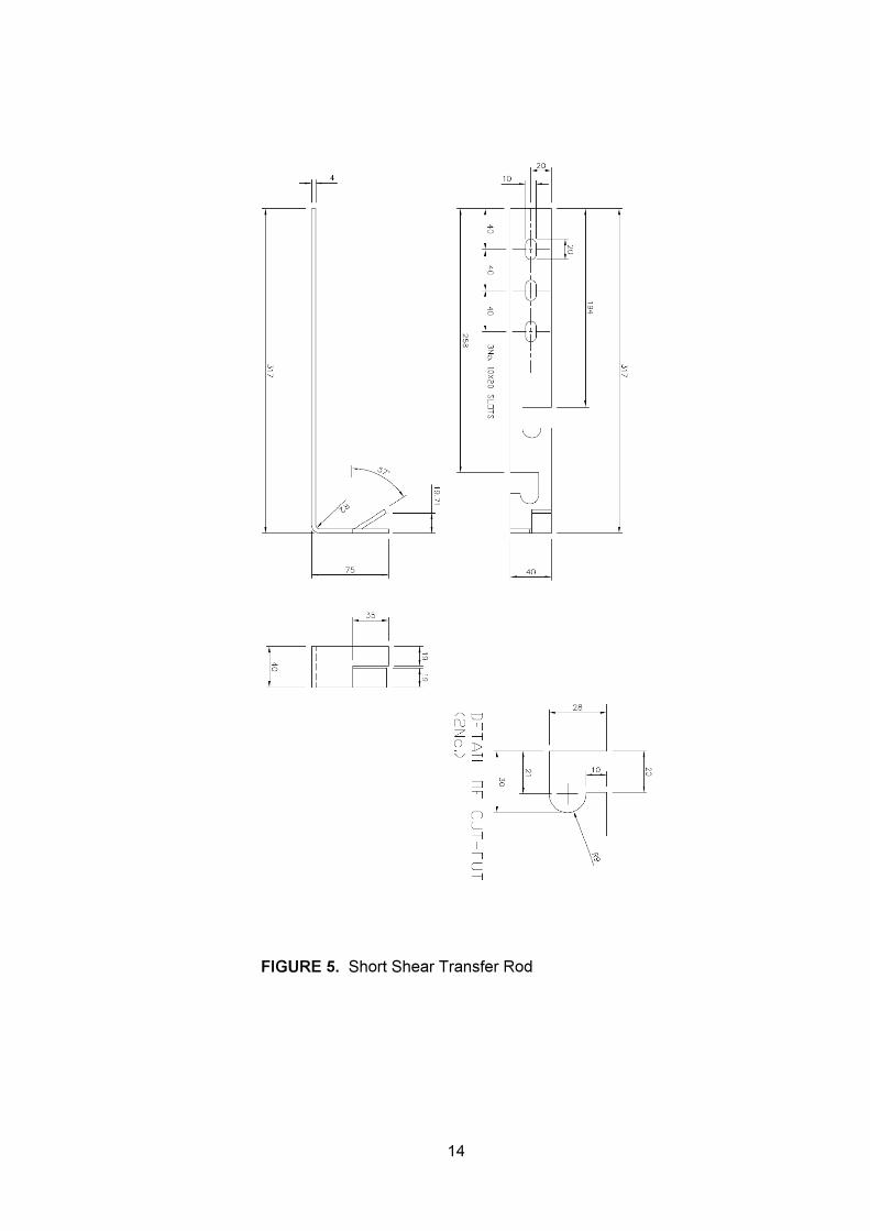
FIGURE 5. Short Shear Transfer Rod
14
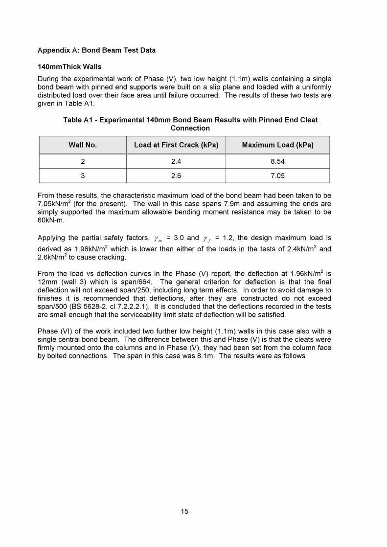
Appendix A: Bond Beam Test Data
140mmThick WallsDuring the experimental work of Phase (V), two low height (1.1m) walls containing a singlebond beam with pinned end supports were built on a slip plane and loaded with a uniformly distributed load over their face area until failure occurred. The results of these two tests are given in Table A1.
Table A1 - Experimental 140mm Bond Beam Results with Pinned End Cleat Connection
Wall No. Load at First Crack (kPa) Maximum Load (kPa)
2 2.4 8.54
3 2.6 7.05
From these results, the characteristic maximum load of the bond beam had been taken to be7.05kN/m2 (for the present). The wall in this case spans 7.9m and assuming the ends aresimply supported the maximum allowable bending moment resistance may be taken to be60kN-m.
Applying the partial safety factors, mJ = 3.0 and fJ = 1.2, the design maximum load isderived as 1.96kN/m2 which is lower than either of the loads in the tests of 2.4kN/m2 and2.6kN/m2 to cause cracking.
From the load vs deflection curves in the Phase (V) report, the deflection at 1.96kN/m2 is12mm (wall 3) which is span/664. The general criterion for deflection is that the finaldeflection will not exceed span/250, including long term effects. In order to avoid damage tofinishes it is recommended that deflections, after they are constructed do not exceedspan/500 (BS 5628-2, cl 7.2.2.2.1). It is concluded that the deflections recorded in the tests are small enough that the serviceability limit state of deflection will be satisfied.
Phase (VI) of the work included two further low height (1.1m) walls in this case also with asingle central bond beam. The difference between this and Phase (V) is that the cleats werefirmly mounted onto the columns and in Phase (V), they had been set from the column faceby bolted connections. The span in this case was 8.1m. The results were as follows
15

Table A2 - Experimental 140mm Bond Beam Results with Fixed End Cleat Connection
Wall No. Load at First Crack (kPa) Maximum Load (kPa)
1 4.0 9.0
2 4.2 11.6
In this case, the greater fixity had clearly an effect in delaying cracking and allowing greater loads to be achieved. Using the same partial factors as above would give estimates of thedesign loads as 2.5kN/m2 and 3.2kN/m2 which are again comfortably below the cracking loads. The deflections at these loads were span/582 and span/2862. At this stage, it is considered prudent to use 60kN-m as the maximum allowable moment for the beam asalthough 9kN/m2 and 11.6kN/m2 were the recorded maximum loads at loads in excess ofapproximately 7kN/m2 there was a change in load:deflection behaviour i.e. a reduced rate ofdeflection increase with increased load. It is assumed that the wall was starting to deflect plastically in these cases, and hence the higher load capacities have not been utilized.
190mm Thick Walls
During phase (IX) three 190mm thick bond beam walls each 8.1m x 1.1m were tested andproduced a wide variance in first crack and ultimate loads. The results of these three testsare given in Table A3.
Table A3 - Experimental 190mm Bond Beam Results with Fixed End Cleat Connection
Wall No. Load at First Crack (kPa) Maximum Load (kPa)
1 10.8 21.1
2 14.9 21.7
3 3.0 5.5
The results from the first two walls gave loads at first crack of 10.8kPa and 14.9kPa respectively, with failure loads close to 22kPa. Due to loading and construction issues withthe third wall a very conservative view has been taken of these results.
The maximum allowable bending moment has been taken to be 190/140 times that for the 140mm wall i.e. 80kN-m. This equates to a load of 8.7kPa so is less than the recorded load at which the wall first cracked. Bearing in mind that this would mean the design load would be limited to 2.9kPa and taking into account the characteristic lateral load would be limited to 2.4kPa which is the lowest cracking load experienced with the 140mm walls. Consequently the recommended values are very conservative and there is clearly no needfor a serviceability check.
fJ
16

Appendix B: Bond Column Test Data
140mm Thick Columns
During Phase (VIII) of the experimental work, four columns, each 140mm thick, 0.89m wideand either 3m or 5m high were tested under lateral load.
The columns consisted of one reinforced block with two 16mm reinforcing bars, either one ineach of the blocks two cells or two spaced similarly within a single rectangular cell. Theresults are given in Table B2.
Table B1 – Experimental Results for 140mm Thick Columns
Column No.
Cell Type Height (m) Maximum
Load (kN/m) Failure Mode
Maximum Bending Moment
(kN-m) 3 Double 2.7 35.6 Air Bag 32.4
4 Single 2.7 32.0 Air Bag 29.2
5 Double 4.95 8.45 Air Bag 25.9
6 Single 4.95 10.45 Section Failure 31.9
From these results, the maximum allowable bending moment has been taken as 30kN-m.This is based upon column no. 6 where the maximum bending moment was 31.9kN-m andcolumn 3 where the failure load was greater when the air bag burst. Applying a safety factor of 3 gives a maximum design bending moment resistance as 10kN-m. Applying a furthersafety factor for loads fJ of 1.2, the deflections at the characteristic bending moment thatcould be applied to the columns has been determined. These are given in Table B2.
Table B2 – Serviceability Deflections
Column No. Deflection (mm) Ratio to Span
3 4.6 586
4 2.2 1227 5 6.6 750 6 1.2 4125
All these deflections are well below the span/500 recommended for long term deflections so as not to cause damage to finishes. It is therefore concluded that within the column heights tested i.e. not more than 5m that if the maximum design bending moment is limited to 10 kN-m theserviceability limit state will be met.
17

190mm Thick Columns
During Phase (Vlll) of the experimental work a further four 190mm thick columns weretested. The results are given in Table B3.
Table B3 – Experimental Results for 190mm Thick Columns
Column No.
Cell Type Height (m) Maximum
Load (kN/m) Failure Mode
Maximum Bending Moment
(kN-m)
1 Single 2.7 35.3 Air Bag 32.2
2 Double 2.7 34.9 Air Bag 31.8
7 Double 4.95 22.6 Air Bag 61.6
8 Single 4.95 35.1 Air Bag 107.5
All of the above results (Table B3) show different maximum bending moments due toultimate failure of the loading air bags. Both of the 3m high columns achieved similar maximum bending moments of approximately 32kN-m. There was variation in the 5m highcolumn results which has led to the development of a conservative alternative design approach (Table B4). This shows the applied test loads and bending moments achieved atspan/500.
Table B4 – Actions to Cause Limiting Deflection
Column No. Span/500 (mm) Load (kN/m) Bending Moment
(kN-m)
1 5.4 26.7 32.2
2 5.4 24.6 31.8
7 9.9 6.5 19.9
8 9.9 4.0 12.3
The results here show a fairly homogenous set of bending moments with column 8 giving aslightly low result. If we take column 8 as the critical one, here a design bending moment of
fJ x 12.3 i.e.14.8 is indicated. Clearly given the other results if this is taken as 15kN-m, itprovides a conservative limit. In addition this is very close to that which might be expected from the 140mm columns where the lowest accrual measured design bending moment was(31.9 y 3) 10.6kN-m and simply multiplying this up by the wall width ratio 190/140 gives avalue of 14.4kN-m and at that value a serviceability check is not needed. As all the maximum bending moments were limited by the failure of the loading air bags, further testingwould increase this 190mm bond column design bending moment value.
Note: The experimental data on the columns relates to those where an internal web separated the two formedvoids and those where it had been removed (referred to single and double cell type). The preferredmethod of construction is to now use units with a single formed void and no internal web
18

CERAMQueens Road, Penkhull,
Stoke-on-Trent, Staffordshire ST4 7LQ, United Kingdom
Tel: +44 (0)1782 764428 Tel (UK customers): 0845 026 0902
Fax: +44 (0)1782 412331Email: [email protected]
www.ceram.com/structures