l-200j_series_manual_e_060300_web-1.pdf - Operating ...
36
Operating Manual Thank you for purchasing this product. Please read the operating manual carefully and use this product properly. Coating Thickness Testers LE-200J/LH-200J/LZ-200J
-
Upload
khangminh22 -
Category
Documents
-
view
4 -
download
0
Transcript of l-200j_series_manual_e_060300_web-1.pdf - Operating ...
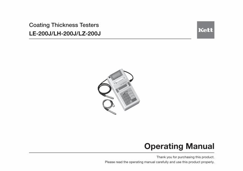
Operating ManualThank you for purchasing this product.
Please read the operating manual carefully and use this product properly.
Coating Thickness TestersLE-200J/LH-200J/LZ-200J
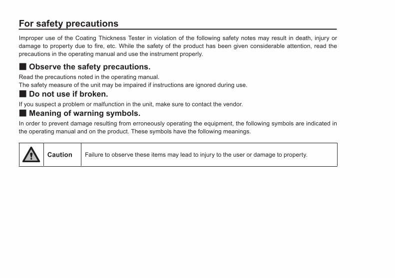
For safety precautionsImproper use of the Coating Thickness Tester in violation of the following safety notes may result in death, injury or damage to property due to fire, etc. While the safety of the product has been given considerable attention, read the precautions in the operating manual and use the instrument properly.
■ Observe the safety precautions.Read the precautions noted in the operating manual.The safety measure of the unit may be impaired if instructions are ignored during use.■ Do not use if broken.If you suspect a problem or malfunction in the unit, make sure to contact the vendor.■ Meaning of warning symbols.In order to prevent damage resulting from erroneously operating the equipment, the following symbols are indicated in the operating manual and on the product. These symbols have the following meanings.
Caution Failure to observe these items may lead to injury to the user or damage to property.
Contents
1. Measuring Principles and Characteristics ............................................................................ 4
2. Instrument view ..................................................................................................................... 6
3. Accessories .......................................................................................................................... 7
4. Keypad Fanctions ................................................................................................................. 8
5.Specifications ........................................................................................................................ 11
6. Preparations for Operation ................................................................................................... 12
7. Measuring Procedure ........................................................................................................... 21
8. Functions ..............................................................................................................................25
9. Master Calibration. ................................................................................................................31
10. Notes for Measuring and Handling ......................................................................................32
4
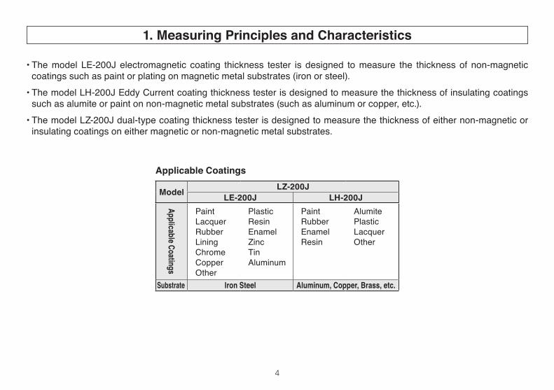
• The model LE-200J electromagnetic coating thickness tester is designed to measure the thickness of non-magnetic coatings such as paint or plating on magnetic metal substrates (iron or steel).
• The model LH-200J Eddy Current coating thickness tester is designed to measure the thickness of insulating coatings such as alumite or paint on non-magnetic metal substrates (such as aluminum or copper, etc.).
• The model LZ-200J dual-type coating thickness tester is designed to measure the thickness of either non-magnetic or insulating coatings on either magnetic or non-magnetic metal substrates.
1. Measuring Principles and Characteristics
Applicable Coatings
Model LZ-200JLE-200J LH-200J
Applicable Coatings
PaintLacquerRubberLiningChromeCopperOther
PlasticResinEnamelZincTinAluminum
PaintRubberEnamelResin
AlumitePlasticLacquerOther
Substrate Iron Steel Aluminum, Copper, Brass, etc.
5
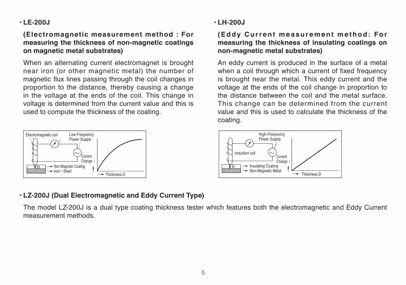
• LE-200J (Electromagnetic measurement method : For
measuring the thickness of non-magnetic coatings on magnetic metal substrates)
When an alternating current electromagnet is brought near iron (or other magnetic metal) the number of magneticfluxlinespassingthroughthecoilchangesinproportion to the distance, thereby causing a change in the voltage at the ends of the coil. This change in voltage is determined from the current value and this is used to compute the thickness of the coating.
• LH-200J ( E d d y C u r r e n t m e a s u r e m e n t m e t h o d: Fo r
measuring the thickness of insulating coatings on non-magnetic metal substrates)
An eddy current is produced in the surface of a metal whenacoil throughwhichacurrentoffixedfrequencyis brought near the metal. This eddy current and the voltage at the ends of the coil change in proportion to the distance between the coil and the metal surface. This change can be determined from the current value and this is used to calculate the thickness of the coating.
• LZ-200J (Dual Electromagnetic and Eddy Current Type) The model LZ-200J is a dual type coating thickness tester which features both the electromagnetic and Eddy Current
measurement methods.
Low-Frequency Power Supply
Non-Magnetic CoatingIron • Steel
Thickness D
Electromagnetic coil
Current Change i
i
Induction coil
Insulating CoatingNon-Magnetic Metal
Thickness D
High-Frequency Power Supply
Current Change i
6
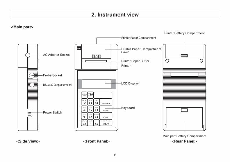
Printer Paper Compartment
Printer Paper Compar tment Cover
Printer Paper CutterPrinter
LCD Display
Keyboard
AC Adapter Socket
Probe Socket
RS232C Output terminal
Power Switch
Printer Battery Compartment
Main part Battery Compartment <Side View> <Front Panel> <Rear Panel>
<Main part>
2. Instrument view
7
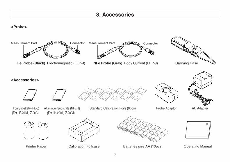
Printer Paper Calibration Foilcase Batteries size AA (10pcs) Operating Manual
Iron Substrate (FE-J) Aluminum Substrate (NFE-J) Standard Calibration Foils (6pcs) Probe Adaptor AC Adapter (For LE-200J,LZ-200J) (For LH-200J,LZ-200J)
ConnectorMeasurement Part Connector
Fe Probe (Black) Electromagnetic (LEP-J) Carrying CaseNFe Probe (Gray) Eddy Current (LHP-J)
<Probe>
Measurement Part
<Accessories>
3. Accessories
8
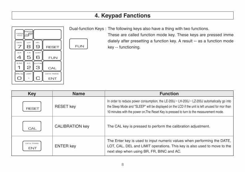
Key Name Function
RESET keyIn order to reduce power consumption, the LE-200J • LH-200J • LZ-200J automatically go into the Sleep Mode and "SLEEP" will be displayed on the LCD if the unit is left unused for mor than 10 minutes with the power on.The Reset Key is pressed to turn to the measurement mode.
CALIBRATION key The CAL key is pressed to perform the calibration adjustment.
ENTER keyThe Enter key is used to input numeric values when performing the DATE, LOT, CAL, DEL and LIMIT operations. This key is also used to move to the nextstepwhenusingBR,FR,BINCandAC.
Dual-function Keys : The following keys also have a thing with two functions. These are called function mode key. These keys are pressed imme
diately after presetting a function key. A result -- as a function mode key -- functioning.
4. Keypad Fanctions
9
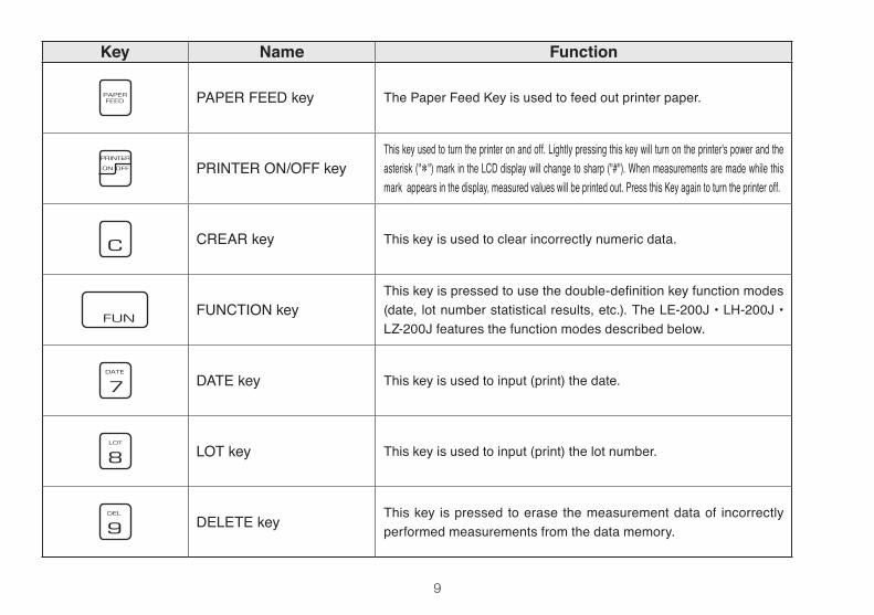
Key Name Function
PAPER FEED key The Paper Feed Key is used to feed out printer paper.
PRINTER ON/OFF keyThis key used to turn the printer on and off. Lightly pressing this key will turn on the printer's power and the asterisk ("*") mark in the LCD display will change to sharp ("#"). When measurements are made while this mark appears in the display, measured values will be printed out. Press this Key again to turn the printer off.
CREAR key This key is used to clear incorrectly numeric data.
FUNCTION keyThiskeyispressedtousethedouble-definitionkeyfunctionmodes(date, lot number statistical results, etc.). The LE-200J • LH-200J • LZ-200J features the function modes described below.
DATE key This key is used to input (print) the date.
LOT key This key is used to input (print) the lot number.
DELETE key This key is pressed to erase the measurement data of incorrectly performed measurements from the data memory.
10
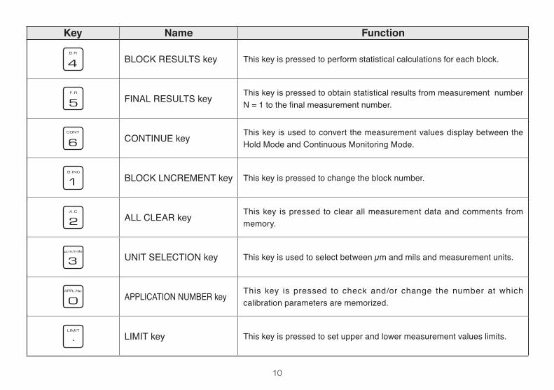
Key Name Function
BLOCK RESULTS key This key is pressed to perform statistical calculations for each block.
FINAL RESULTS key This key is pressed to obtain statistical results from measurement number N=1tothefinalmeasurementnumber.
CONTINUE key This key is used to convert the measurement values display between the Hold Mode and Continuous Monitoring Mode.
BLOCK LNCREMENT key This key is pressed to change the block number.
ALL CLEAR key This key is pressed to clear all measurement data and comments from memory.
UNIT SELECTION key This key is used to select between µm and mils and measurement units.
APPLICATION NUMBER key This key is pressed to check and/or change the number at which calibration parameters are memorized.
LIMIT key This key is pressed to set upper and lower measurement values limits.
11
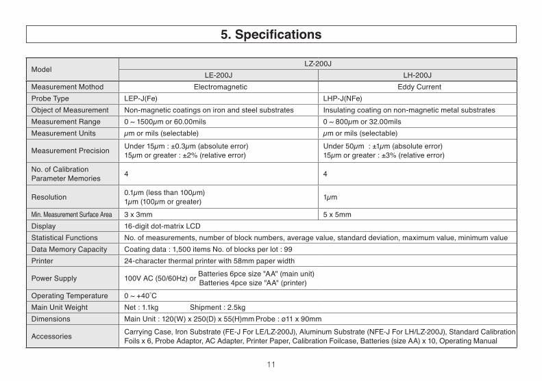
5. Specifications
ModelLZ-200J
LE-200J LH-200JMeasurement Mothod Electromagnetic Eddy CurrentProbe Type LEP-J(Fe) LHP-J(NFe)Object of Measurement Non-magnetic coatings on iron and steel substrates Insulating coating on non-magnetic metal substratesMeasurement Range 0 ~ 1500µm or 60.00mils 0 ~ 800µm or 32.00milsMeasurement Units µm or mils (selectable) µm or mils (selectable)
Measurement Precision Under 15µm : ±0.3µm (absolute error)15µm or greater : ±2% (relative error)
Under 50µm : ±1µm (absolute error)15µm or greater : ±3% (relative error)
No. of CalibrationParameter Memories 4 4
Resolution 0.1µm (less than 100µm)1µm (100µm or greater) 1µm
Min. Measurement Surface Area 3x3mm 5x5mmDisplay 16-digitdot-matrixLCDStatistical Functions No.ofmeasurements,numberofblocknumbers,averagevalue,standarddeviation,maximumvalue,minimumvalueData Memory Capacity Coating data : 1,500 items No. of blocks per lot : 99Printer 24-character thermal printer with 58mm paper width
Power Supply 100V AC (50/60Hz) or Batteries 6pce size "AA" (main unit)Batteries 4pce size "AA" (printer)
Operating Temperature 0~+40˚CMain Unit Weight Net : 1.1kg Shipment : 2.5kgDimensions MainUnit:120(W)x250(D)x55(H)mmProbe:ø11x90mm
Accessories Carrying Case, Iron Substrate (FE-J For LE/LZ-200J), Aluminum Substrate (NFE-J For LH/LZ-200J), Standard Calibration Foilsx6,ProbeAdaptor,ACAdapter,PrinterPaper,CalibrationFoilcase,Batteries(sizeAA)x10,OperatingManual
12
1. Measurement Preparations Preparing the power source The LE-200J • LH-200J • LZ-200J have been designed
for use with either 100V/220V AC 50/60 Hz or dry cell batteries as the power supply.
• Running the LE-200J • LH-200J • LZ-200J on a 100V/220V AC power supply
Turn the main unit's power switch off and insert the plug of the supplied AC adapter into the AC adapter Socket ontherightsideofthemainunit.NextconnecttheACadapter to a 100V/220V power supply socket.
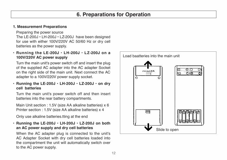
• Running the LE-200J • LH-200J • LZ-200J • on dry cell batteries
Turn the main unit's power switch off and then insert batteries into the rear battery compartments.
MainUnitsection:1.5V(sizeAAalkalinebatteries)x6 Printersection:1.5V(sizeAAalkalinebatteries)x4 Only use alkaline batteries.tting at the end• Running the LE-200J • LH-200J • LZ-200J on both
an AC power supply and dry cell batteries When the AC adapter plug is connected to the unit's
AC Adapter Socket with dry cell batteries loaded into the compartment the unit will automatically switch over to the AC power supply.
Load baatteries into the main unit
Slide to open
6. Preparations for Operation
13
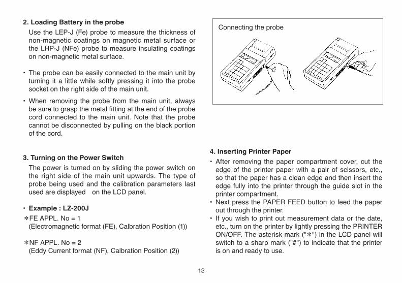
2. Loading Battery in the probe Use the LEP-J (Fe) probe to measure the thickness of
non-magnetic coatings on magnetic metal surface or the LHP-J (NFe) probe to measure insulating coatings on non-magnetic metal surface.
• The probe can be easily connected to the main unit by turning it a little while softly pressing it into the probe socket on the right side of the main unit.
• When removing the probe from the main unit, always besuretograspthemetalfittingattheendoftheprobecord connected to the main unit. Note that the probe cannot be disconnected by pulling on the black portion of the cord.
3. Turning on the Power Switch The power is turned on by sliding the power switch on
the right side of the main unit upwards. The type of probe being used and the calibration parameters last used are displayed on the LCD panel.
• Example : LZ-200J*FE APPL. No = 1 (Electromagnetic format (FE), Calbration Position (1))
*NF APPL. No = 2 (Eddy Current format (NF), Calbration Position (2))
Connecting the probe
4. Inserting Printer Paper• After removing the paper compartment cover, cut the
edge of the printer paper with a pair of scissors, etc., so that the paper has a clean edge and then insert the edge fully into the printer through the guide slot in the printer compartment.
• NextpressthePAPERFEEDbuttontofeedthepaperout through the printer.
• If you wish to print out measurement data or the date, etc., turn on the printer by lightly pressing the PRINTER ON/OFF. The asterisk mark ("*") in the LCD panel will switch to a sharp mark ("#") to indicate that the printer is on and ready to use.
14
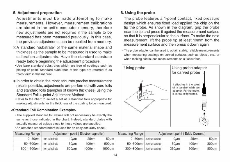
6. Using the probe Theprobe featuresa1-pointcontact, fixedpressuredesignwhichensuresfixed loadappliedthechiponthetip the probe. As shown in the diagram, grip the probe near the tip and press it against the measurement surface sothatitisperpendiculartothesurface.Tomakethenextmeasurement, lift the probe tip at least 10mm from the measurement surface and then press it down again.
• The probe adapter can be used to obtain stable, reliable measurements when measuring coatings on curved surfaces such as pipes , etc., or whenmakingcontinuousmeasurementsonaflatsurface.
5. Adjustment preparation Adjustments must be made at tempting to make
measurements. However, measurement calibrations are stored in theunit’s computermemory, thereforenew adjustments are not required if the sample to be measured has been measured previously. In this case, the previous adjustments can be recalled from memory.
1 A standard "substrate" of the same material,shape and thickness as the sample to be measured is used to make calibration adjustments. Have the standard substrate ready before beginning the adjustment procedure.
• Use bare standard substrates which are free of coatings such as plating or paint. Standard substrates of this type are referred to as "zero foils" in this manual.
2 In order to obtain the most accurate precise measurement results possible, adjustments are performed with zero foils and standard foils (samples of known thickness) using the Standard Foil 4-point Adjustment Method.
• Refer to the chart to select a set of 3 standard foils appropriate for making adjustments for the thickness of the coating to be measured.
<Standard Foil Combination Example>•Thesuppliedstandardfoilvalueswillnotnecessarilybeexactlythesame as those indicated in the chart. Instead, standard plates with actually measured values close to these values are supplied.
• An attached standard board is used for an easy accuracy check.
Using probe adapterfor carved probe
It attaches in the point of a probe wi th an adapter. Furthermore, a screw is tightened.
Using probe
Measuring Range Adjustment point ( Electromagnetic ) Measuring Range Adjustment point ( Eddy Current )0~50µm Iron substrate 10µm 25µm 50µm 0~50µm Aluminum substrate 10µm 25µm 50µm
50~500µm Iron substrate 50µm 100µm 500µm 50~300µm Aluminum substrate 50µm 100µm 300µm500~1500µm Iron substrate 500µm 1000µm 1500µm 300~800µm Aluminum substrate 350µm 500µm 800µm
15
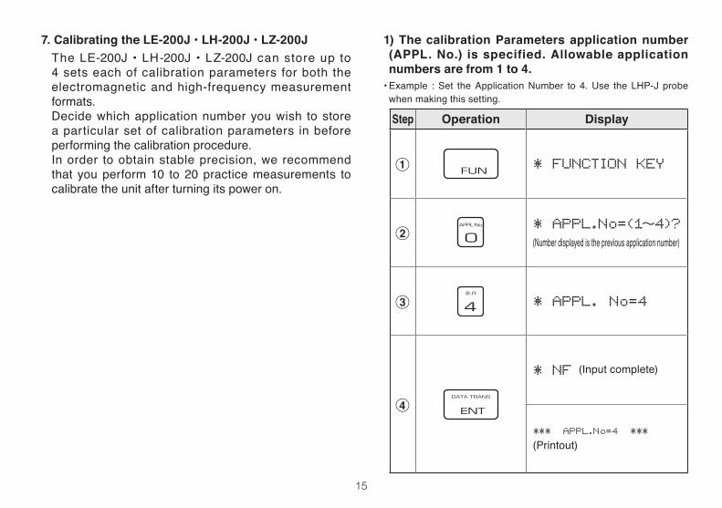
Step Operation Display
1 * FUNCTION KEY
2* APPL.No=(1〜4)?(Number displayed is the previous application number)
3 * APPL. No=4
4
* NF
*** APPL.No=4 ***
(Printout)
7. Calibrating the LE-200J • LH-200J • LZ-200J The LE-200J • LH-200J • LZ-200J can store up to
4 sets each of calibration parameters for both the electromagnetic and high-frequency measurement formats.
Decide which application number you wish to store a particular set of calibration parameters in before performing the calibration procedure.
In order to obtain stable precision, we recommend that you perform 10 to 20 practice measurements to calibrate the unit after turning its power on.
1) The calibration Parameters application number (APPL. No.) is specified. Allowable application numbers are from 1 to 4.•Example :Set theApplicationNumber to 4.Use theLHP-Jprobewhen making this setting.
(Input complete)
16
Step Operation Display Explanation
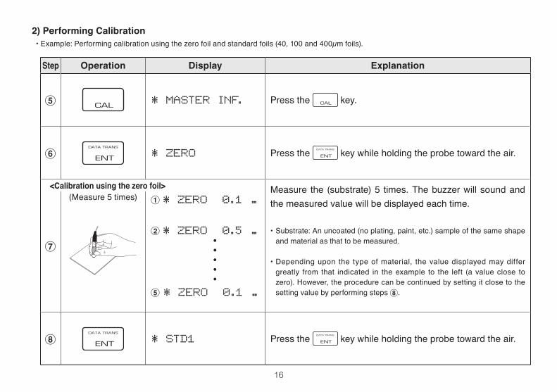
5 * MASTER INF. Press the key.
6 * ZERO Press the key while holding the probe toward the air.
7
(Measure 5 times) 1* ZERO 0.1 ..
2* ZERO 0.5 ..
5* ZERO 0.1 ..
Measure the (substrate) 5 times. The buzzer will sound and the measured value will be displayed each time.
• Substrate: An uncoated (no plating, paint, etc.) sample of the same shape and material as that to be measured.
• Depending upon the type of material, the value displayed may differ greatly from that indicated in theexample to the left (a value close tozero). However, the procedure can be continued by setting it close to the setting value by performing steps 8.
8 * STD1 Press the key while holding the probe toward the air.
2) Performing Calibration•Example:Performingcalibrationusingthezerofoilandstandardfoils(40,100and400µmfoils).
・・・・・
<Calibration using the zero foil>
17
Step Operation Display Explanation
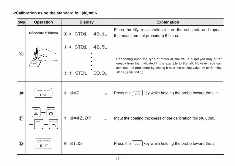
9
(Measure 5 times) 1* STD1 40.1..
2* STD1 40.5..
5* STD1 39.9..
Place the 40µm calibration foil on the substrate and repeat the measurement procedure 5 times.
• Depending upon the type of material, the value displayed may differ greatly from that indicated in theexample to the left.However, you cancontinue the procedure by setting it near the setting value by performing steps 0! and @.
0 * d=? .. Press the key while holding the probe toward the air.
!
* d=40.0? .. Input the coating thickness of the calibration foil (40.0µm).
@ * STD2 Press the key while holding the probe toward the air.
・・・・・
<Calibration using the standard foil (40µm)>
18
Step Operation Display Explanation
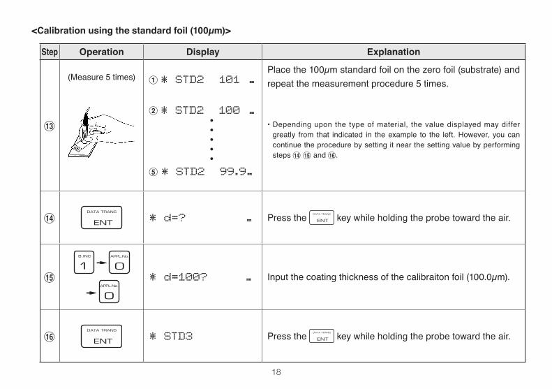
#
(Measure 5 times) 1* STD2 101 ..
2* STD2 100 ..
5* STD2 99.9..
Place the 100µm standard foil on the zero foil (substrate) and repeat the measurement procedure 5 times.
• Depending upon the type of material, the value displayed may differ greatly from that indicated in theexample to the left.However, you cancontinue the procedure by setting it near the setting value by performing steps $% and .̂
$ * d=? .. Press the key while holding the probe toward the air.
%
* d=100? .. Input the coating thickness of the calibraiton foil (100.0µm).
^ * STD3 Press the key while holding the probe toward the air.
<Calibration using the standard foil (100µm)>
・・・・・
19
Step Operation Display Explanation
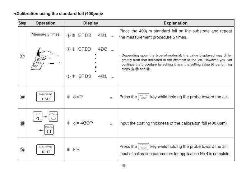
&
(Measure 5 times) 1* STD3 401 ..
2* STD3 400 ..
5* STD3 401 ..
Place the 400µm standard foil on the substrate and repeat the measurement procedure 5 times.
• Depending upon the type of material, the value displayed may differ greatly from that indicated in theexample to the left.However, you cancontinue the procedure by setting it near the setting value by performing steps *(and).
* * d=? .. Press the key while holding the probe toward the air.
(
* d=400? .. Input the coating thickness of the calibraiton foil (400.0µm).
) * FEPress the key while holding the probe toward the air.Input of calibration parameters for application No.4 is complete.
<Calibration using the standard foil (400µm)>
・・・・・
20
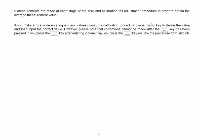
• 5 measurements are made at each stage of the zero and calibration foil adjustment procedure in order to obtain the average measurement value.
• If you make errors while entering numeric values during the calibration procedure, press the key to delete the value and then input the correct value. However, please note that corrections cannot be made after the key has been pressed. If you press the key after entering incorrect values, press the key resume the procedure from step 5.
21
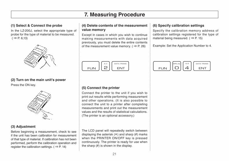
(6) Specify calibration settingsSpecify the calibration memory address of calibration settings registered for the type of material being measured. ( ⇒ P. 15)
Example:SettheApplicationNumberto4.
(1) Select & Connect the probe In the LZ-200J, select the appropriate type of probe for the type of material to be measured. ( ⇒ P. 6,13)
(2) Turn on the main unit's powerPress the ON key.
(3) AdjustmentBefore beginning a measurement, check to see if the unit has been calibration for measurement of that type of material. If calibration has not been performed, perform the calibration operation and register the calibration settings. ( ⇒ P. 14)
(4) Delete contents of the measurement value memoryExceptincasesinwhichyouwishtocontinuemaking measurements with data acquired previously, you must delete the entire contents of the measurement value memory. ( ⇒ P. 26)
(5) Connect the printerConnect the printer to the unit if you wish to print out results while performing measurement and other operations. (It is also possible to connect the unit to a printer after completing measurements and print out the measurement values and the results of statistical calculations. (The printer is an optional accessory.)
The LCD panel will repeatedly switch between displaying the asterisk (*) and sharp (#) marks when the PRINTER ON/OFF key is pressed continuously. The printer is ready for use when the sharp (#) is shown in the display.
7. Measuring Procedure
22
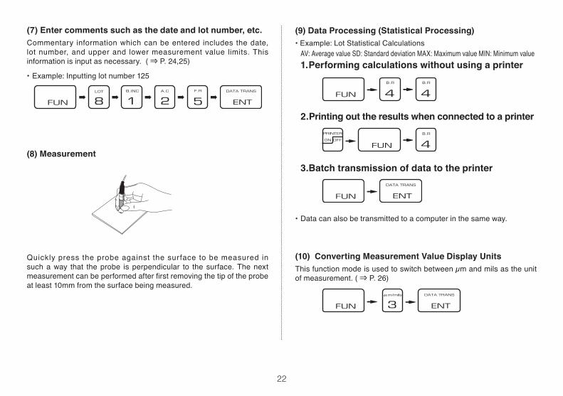
(9) Data Processing (Statistical Processing)•Example:LotStatisticalCalculations AV:AveragevalueSD:StandarddeviationMAX:MaximumvalueMIN:Minimumvalue
1. Performing calculations without using a printer
2.Printing out the results when connected to a printer
3. Batch transmission of data to the printer
• Data can also be transmitted to a computer in the same way.
(10) Converting Measurement Value Display UnitsThis function mode is used to switch between µm and mils as the unit of measurement. ( ⇒ P. 26)
(7) Enter comments such as the date and lot number, etc.Commentary information which can be entered includes the date, lot number, and upper and lower measurement value limits. This information is input as necessary. ( ⇒ P. 24,25)
•Example:Inputtinglotnumber125
(8) Measurement
Quickly press the probe against the surface to be measured in suchaway that theprobe is perpendicular to the surface.Thenextmeasurementcanbeperformedafterfirstremovingthetipoftheprobeat least 10mm from the surface being measured.
➡ ➡ ➡ ➡ ➡
23
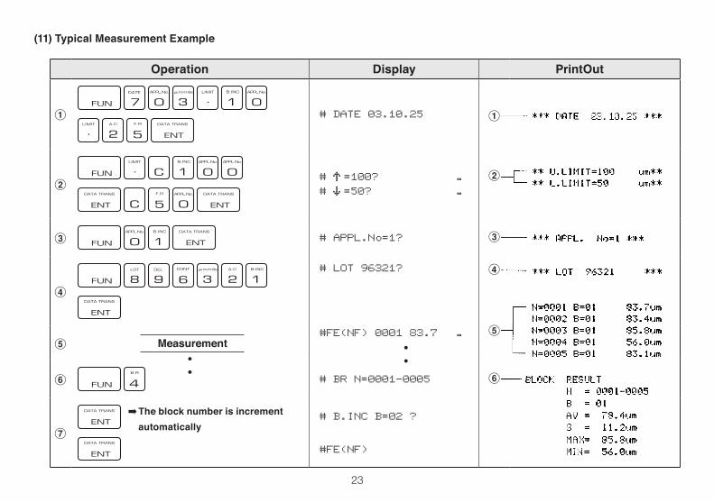
Operation Display PrintOut
1
# DATE 03.10.25 1
2
# =100? ..# =50? ..
2
3 # APPL.No=1? 3
4
# LOT 96321? 4
5 Measurement#FE(NF) 0001 83.7 .. 5
6 # BR N=0001-0005 6
7
# B.INC B=02 ?
#FE(NF)
(11) Typical Measurement Example
➡ The block number is increment automatically
・・・
・
24
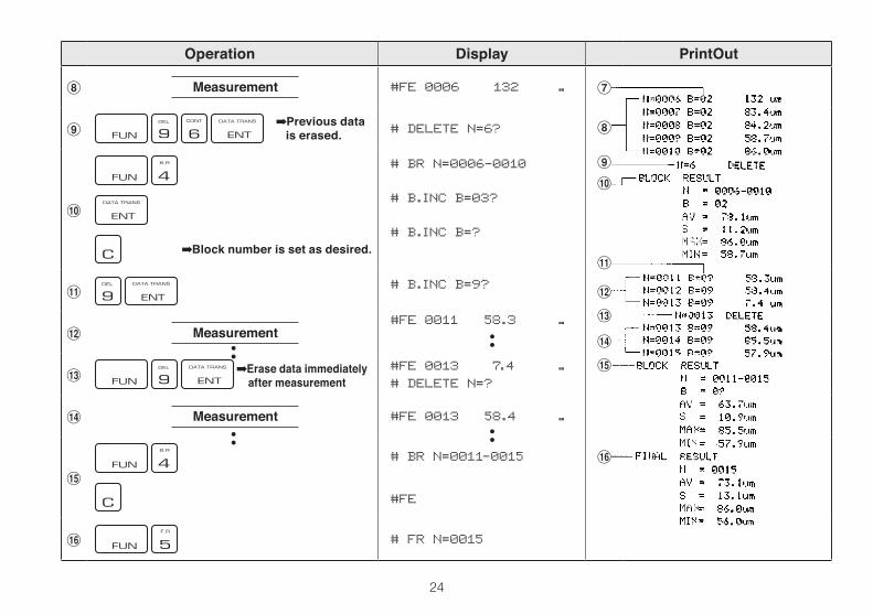
Operation Display PrintOut
8 Measurement #FE 0006 132 .. 7
9 # DELETE N=6? 8
0
# BR N=0006-0010
# B.INC B=03?
# B.INC B=?
9
0
!
! # B.INC B=9?@
@ Measurement#FE 0011 58.3 .. #
$
# #FE 0013 7.4 ..# DELETE N=?
%
$ Measurement #FE 0013 58.4 ..
%
# BR N=0011-0015
#FE
^
^ # FR N=0015
➡Previous data is erased.
➡Erase data immediately after measurement
➡Block number is set as desired.
・・
・・
・・
・・
25
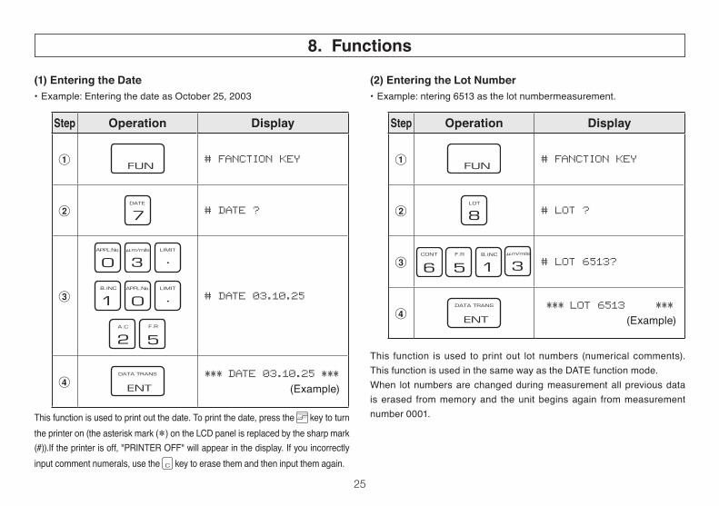
(1) Entering the Date•Example:EnteringthedateasOctober25,2003
(2) Entering the Lot Number•Example:ntering6513asthelotnumbermeasurement.
This function is used to print out the date. To print the date, press the key to turn the printer on (the asterisk mark (*) on the LCD panel is replaced by the sharp mark (#)).If the printer is off, "PRINTER OFF" will appear in the display. If you incorrectly input comment numerals, use the key to erase them and then input them again.
This function is used to print out lot numbers (numerical comments). This function is used in the same way as the DATE function mode.When lot numbers are changed during measurement all previous data is erased from memory and the unit begins again from measurement number 0001.
8. Functions
Step Operation Display
1 # FANCTION KEY
2 # DATE ?
3
# DATE 03.10.25
4*** DATE 03.10.25 ***
(Example)
Step Operation Display
1 # FANCTION KEY
2 # LOT ?
3 # LOT 6513?
4*** LOT 6513 ***
(Example)
26
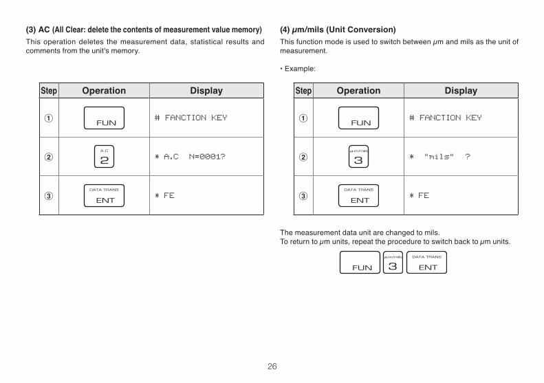
(3) AC (All Clear: delete the contents of measurement value memory)This operation deletes the measurement data, statistical results and comments from the unit's memory.
(4) µm/mils (Unit Conversion)This function mode is used to switch between µm and mils as the unit of measurement.
•Example:
The measurement data unit are changed to mils.To return to µm units, repeat the procedure to switch back to µm units.
Step Operation Display
1 # FANCTION KEY
2 * A.C N=0001?
3 * FE
Step Operation Display
1 # FANCTION KEY
2 * "mils" ?
3 * FE
27
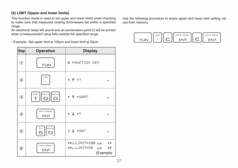
(5) LIMIT (Upper and lower limits)This function mode is used to set upper and lower limits when checking tomakesure thatmeasuredcoating thicknesses fallwithinaspecifiedrange.Anelectronicbeepwillsoundandanexclamationpoint(!)willbeprintedwhenameasurementvaluefallsoutsidethespecifiedrange.
•Example:Setupperlimitat100µmandlowerlimitat50µm
Use the following procedure to erase upper and lower limit setting val-ues from memory.
Step Operation Display
1 # FANCTION KEY
2 * =? ..
3 * =100? ..
4 * =? ..
5 * =50? ..
6
**U.LIMIT=100 **
**L.LIMIT=50 **
(Example)
28
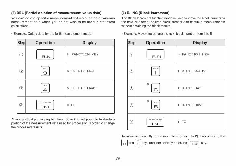
(6) B. INC (Block Increment)The Block Increment function mode is used to move the block number to thenextoranotherdesiredblocknumberandcontinuemeasurementswithout obtaining the block results.
•Example:Move(increment)thenextblocknumberfrom1to5.
(6) DEL (Partial deletion of measurement value data)You can delete specific measurement values such as erroneous measurement data which you do not wish to be used in statistical calculations.
•Example:Deletedatafortheforthmeasurementmade.
*
*
Tomovesequentially to thenextblock (from1 to2),skippressing the
and keys and immediately press the key.
Step Operation Display
1 # FANCTION KEY
2 * DELETE N=?
3 * DELETE N=4?
4 * FE
After statistical processing has been done it is not possible to delete a portion of the measurement data used for processing in order to change the processed results.
Step Operation Display
1 # FANCTION KEY
2 * B.INC B=01?
3 * B.INC B=?
4 * B.INC B=5?
5 * FE
29
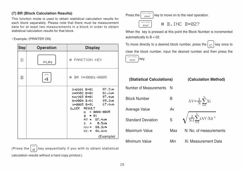
Press the keytomoveontothenextoperation.
# B.INC B=02?
When the key is pressed at this point the Block Number is incremented automatically to B = 02.
To move directly to a desired block number, press the key once to
clear the block number, input the desired number and then press the
key.
(Statistical Calculations) (Calculation Method)
Number of Measurements N
Block Number B
Average Value Av
Standard Deviation S
MaximumValue Max N:No.ofmeasurements
Minimum Value Min Xi: Measurement Data
(7) BR (Block Calculation Results)This function mode is used to obtain statistical calculation results for each block separately. Please note that there must be measurement data for at least two measurements in a block in order to obtain statistical calculation results for that block.
•Example:(PRINTERON)
(Press the key sequential ly i f you with to obtain stat ist ical
calculation results without a hard copy printout.)
Step Operation Display
1 # FANCTION KEY
2 # BR N=0001-0005
(Example)
30
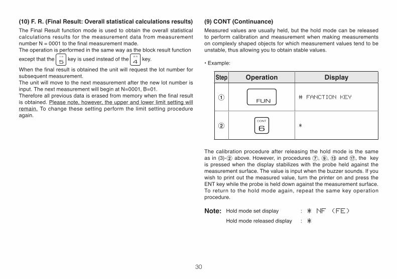
(9) CONT (Continuance)Measured values are usually held, but the hold mode can be released to perform calibration and measurement when making measurements oncomplexlyshapedobjectsforwhichmeasurementvaluestendtobeunstable, thus allowing you to obtain stable values.
•Example:
(10) F. R. (Final Result: Overall statistical calculations results)The Final Result function mode is used to obtain the overall statistical calculations results for the measurement data from measurement numberN=0001tothefinalmeasurementmade.The operation is performed in the same way as the block result functionexceptthatthe key is used instead of the key.
Whenthefinalresultisobtainedtheunitwillrequestthelotnumberforsubsequent measurement.Theunitwillmovetothenextmeasurementafterthenewlotnumberisinput.ThenextmeasurementwillbeginatN=0001,B=01.Thereforeallpreviousdataiserasedfrommemorywhenthefinalresultis obtained. Please note, however, the upper and lower limit setting will remain. To change these setting perform the limit setting procedure again.
The calibration procedure after releasing the hold mode is the same as in (3)-2 above. However, in procedures 7, 9, # and &, the key is pressed when the display stabilizes with the probe held against the measurement surface. The value is input when the buzzer sounds. If you wish to print out the measured value, turn the printer on and press the ENT key while the probe is held down against the measurement surface. To return to the hold mode again, repeat the same key operation procedure.
Note: Hold mode set display : * NF (FE) Hold mode released display : *
Step Operation Display
1 # FANCTION KEY
2 *
31
* ◯ ◯ ◯ ◯ (4-digit number)
* ◯ ◯ ◯ ◯ ◯ (5-digit number)
* MASTER INF.
* ZERO
* FE APPL. No=1
* FE0001 0.0
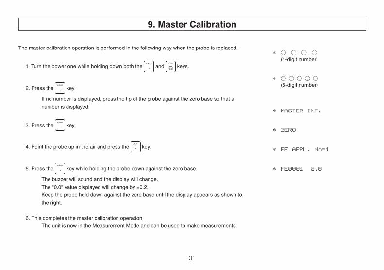
The master calibration operation is performed in the following way when the probe is replaced.
1. Turn the power one while holding down both the and keys.
2. Press the key.
If no number is displayed, press the tip of the probe against the zero base so that a number is displayed.
3. Press the key.
4. Point the probe up in the air and press the key.
5. Press the key while holding the probe down against the zero base.
The buzzer will sound and the display will change. The "0.0" value displayed will change by ±0.2. Keep the probe held down against the zero base until the display appears as shown to the right.
6. This completes the master calibration operation. The unit is now in the Measurement Mode and can be used to make measurements.
9. Master Calibration
32
(1) Confirm the type of material being measured.Be sure to check the type of material and select the correct probe type before beginning measurements.
(2) Do not damage the probe or get it dirty.Accurate measurement results cannot be obtained if the chip on the tip of the probe is damaged or dirty. Do not pound the probeagainstthemeasurementsurfaceormovetheprobelaterallywhileitispresseddownuponthesurface.Whenfinishedmaking measurements, use a soft cloth wet with benzine or alcohol to clean the tip of the probe.
(3) Handle the calibration foils with care.The thickness of the calibration foils has been measured very precisely. You will not be able to obtain accurate measurement results if you use calibration foils which have been scratched, bent or otherwise damaged. Be particularly careful not to subject the thinnest foil, the 10µm foil, to wear.If a standard foil becomes damaged while being used, please contact the dealer from whom you purchased the tester and order a replacement of the same thickness. Although the thickness of replacement foils may slightly different than that of the original foils, this does not pose a problem for calibration adjustments.
10. Notes for Measuring and Handling
33
(4) Replace the batteries immediately if the low-voltage indicator is displayed.The following indicators will be displayed on the LCD panel when the main unit or printer section batteries become weak. Please replace the batteries immediately when these indicators appear.1 % is blinking Both the main unit and printer section batteries are weak.2 * is blinking The main unit's batteries are weak.3 # is blinking This mark will blink in the display when the printer is used and indicates that either the main unit or printer batteries are weak. If the asterisk ("* ") mark dose not blink when the PRINTER ON/OFF button is pressed to turn the printer off, this indicates that the printer section batteries are weak.
(5) Adjustment & InspectionIn order to maintain precise performance the coating thickness testers should be inspected at least once per year.Please contact the merchant from whom you purchasd your unit regarding inspection.
•Measurementofpaperorafilm AftercalibrationonIronorAluminumSubstrate,thethicknessofpaperorafilmcanbemeasuredontheIronorAluminum
Substrate.
• The unit will go into the Sleep Mode and "SLEEP" will appear in the display in order to conserve battery power if the unit is notusedformeasurementformorethanapproximately15minuteswiththepoweron.
MeasurementscannotbemadewhiletheunitisintheSleepMode.Toresumemeasurements,presstheRESETkeytoexittheSleepMode.Making10~20practicemeasurementsafterexitingtheSleepModeorimmediatelyafterturningthepoweron will result in higher measurement precision.


060300
Caution● It is strictly prohibited to transfer part or all of this manual without
permission.● The contents of this manual are subject to change without notice.● The appearances, screens, etc. of the product and accessories
displayed on this manual may differ from the actual ones, however, operations and functions are not affected.
● All efforts have been made to ensure the contents of this manual are accurate. However, if you notice any part to be unclear, incorrect, omitted, or the like in this manual, please contact us.
● Be aware that we are not liable for the effects resulting from opera-tions according to this manual regardless of the items above.