Kinematic design of 3-URU pure rotational parallel mechanism to perform precise motion within a...
12
Meccanica (2011) 46: 89–100 DOI 10.1007/s11012-010-9400-2 PARALLEL MANIPULATORS Kinematic design of 3-URU pure rotational parallel mechanism to perform precise motion within a large workspace Syamsul Huda · Yukio Takeda · Shuta Hanagasaki Received: 3 September 2009 / Accepted: 29 November 2010 / Published online: 10 December 2010 © Springer Science+Business Media B.V. 2010 Abstract We present an optimum design of lower-dof parallel mechanism, a 3-URU pure rotational parallel mechanism that reflects issues of workspace and the position error of the center of rotation of the platform. The uncompensatable error determined by position er- ror of center of rotation was used as an evaluation in- dex for the design. The uncompensatable error index, an index used in the optimum design, was proposed taking into account four sources of errors, represent- ing errors between adjacent joints. Based on the appli- cation of the mechanism and the error index, the ef- fect of the redundant platform orientation parameter was numerically investigated and the design flow of the mechanism was proposed. We made a kinematic design of a mechanism with a large workspace sub- ject to minimization of platform’s position error of the center of rotation. A prototype of mechanism with a large inclination angle of the platform up to 1.3 rad was shown, and its characteristics are also discussed. Keywords Parallel mechanism · Kinematic design · Uncompensatable error · Accuracy · Workspace S. Huda · Y. Takeda ( ) · S. Hanagasaki Department of Mechanical Sciences and Engineering, Tokyo Institute of Technology, Tokyo, Japan e-mail: [email protected] url: http://www.mech.titech.ac.jp/~msd/index-english.htm 1 Introduction In the design stage of robot manipulators, the design parameters highly depend on the performance criteria which are defined based on the application desired. To reduce complexity in the design, the important perfor- mance has to be specified and the design should be done based on it. High accuracy is one of the most important perfor- mance factors considered in the design of robot ma- nipulators. Research on parallel manipulators related to the accuracy have become of great interest because the robots perform accurately besides having higher pay-load and velocity compared to those of serial ones. They thus have a wide range of industrial applications. The degree of freedom (dof) of the output link is used to classify parallel robots into six-dof robots and lower-dof ones. In six-dof robots, the platform as the output link is usually connected by six limbs to the fixed body (base) and the platform motion with six di- mensions is fully controlled by six actuators. On the other hand, in lower-dof parallel robots, the number of limbs is usually the same as the dof of the platform and the motion of the platform is constrained not only by actuators but also by the structure. Therefore, only some part of the output error can be compensated for in a lower-dof robot if there are error sources such as dimensional error of links. However, all components of six-dimensional output error can be compensated for in six-dof ones.
-
Upload
independent -
Category
Documents
-
view
0 -
download
0
Transcript of Kinematic design of 3-URU pure rotational parallel mechanism to perform precise motion within a...

Meccanica (2011) 46: 89–100DOI 10.1007/s11012-010-9400-2
PA R A L L E L M A N I P U L ATO R S
Kinematic design of 3-URU pure rotational parallelmechanism to perform precise motion within a largeworkspace
Syamsul Huda · Yukio Takeda · Shuta Hanagasaki
Received: 3 September 2009 / Accepted: 29 November 2010 / Published online: 10 December 2010© Springer Science+Business Media B.V. 2010
Abstract We present an optimum design of lower-dofparallel mechanism, a 3-URU pure rotational parallelmechanism that reflects issues of workspace and theposition error of the center of rotation of the platform.The uncompensatable error determined by position er-ror of center of rotation was used as an evaluation in-dex for the design. The uncompensatable error index,an index used in the optimum design, was proposedtaking into account four sources of errors, represent-ing errors between adjacent joints. Based on the appli-cation of the mechanism and the error index, the ef-fect of the redundant platform orientation parameterwas numerically investigated and the design flow ofthe mechanism was proposed. We made a kinematicdesign of a mechanism with a large workspace sub-ject to minimization of platform’s position error of thecenter of rotation. A prototype of mechanism with alarge inclination angle of the platform up to 1.3 radwas shown, and its characteristics are also discussed.
Keywords Parallel mechanism · Kinematic design ·Uncompensatable error · Accuracy · Workspace
S. Huda · Y. Takeda (�) · S. HanagasakiDepartment of Mechanical Sciences and Engineering,Tokyo Institute of Technology, Tokyo, Japane-mail: [email protected]: http://www.mech.titech.ac.jp/~msd/index-english.htm
1 Introduction
In the design stage of robot manipulators, the designparameters highly depend on the performance criteriawhich are defined based on the application desired. Toreduce complexity in the design, the important perfor-mance has to be specified and the design should bedone based on it.
High accuracy is one of the most important perfor-mance factors considered in the design of robot ma-nipulators. Research on parallel manipulators relatedto the accuracy have become of great interest becausethe robots perform accurately besides having higherpay-load and velocity compared to those of serial ones.They thus have a wide range of industrial applications.
The degree of freedom (dof) of the output link isused to classify parallel robots into six-dof robots andlower-dof ones. In six-dof robots, the platform as theoutput link is usually connected by six limbs to thefixed body (base) and the platform motion with six di-mensions is fully controlled by six actuators. On theother hand, in lower-dof parallel robots, the number oflimbs is usually the same as the dof of the platformand the motion of the platform is constrained not onlyby actuators but also by the structure. Therefore, onlysome part of the output error can be compensated forin a lower-dof robot if there are error sources such asdimensional error of links. However, all componentsof six-dimensional output error can be compensatedfor in six-dof ones.

90 Meccanica (2011) 46: 89–100
In terms of the application of parallel robots, insome cases, lower-dof parallel robots are more ap-plicable than six-dof ones to the three-axis work ta-ble and the two-axis tool orienting device. Using thelower-dof robots enables the number of actuators andmechanical components as well as complexity in mo-tion control to be reduced. Several works were re-ported regarding the structural synthesis of lower-dofparallel mechanisms including that by Gao et al. [3].
We designed a 3-URU pure rotational parallelmechanism with respect to workspace. When a lower-dof parallel mechanism is used, kinematic error shouldbe carefully considered because the effect of dimen-sional errors on the output motion cannot be compen-sated for by a full-closed loop control or calibration.Such an error is called an ‘uncompensatable error’ inthis paper. A great deal of research [1, 4, 10, 14] hasbeen done on the effect of kinematic error in lower-dof parallel mechanism. In particular, the researchersinvestigated the formulation of sensitivity of the mech-anism with respect to various error sources.
Another challenge in the design of robots is how toobtain an optimum design. Many researchers [8, 9, 11]have studied the optimum design of lower-dof parallelmechanisms. Other researchers [12, 13, 15] used var-ious evaluation indices such as stiffness, velocity andisotropy index. We used the uncompensatable error in-dex that counts the position error as the uncompensat-able error. The index is defined as the deviation of theposition of the center of rotation of the platform in apure rotational mechanism. To obtain accurate outputmotion, such error should be minimized to meet thedesign specification in accuracy. As far as we know,no literature other than our own discusses such errorsin design [7].
The error index was used to design a 3-URU par-allel mechanism with a large workspace. Many workshave been carried out regarding the design of a parallelmechanism with respect to the workspace [2, 5, 10].Some indices were used in such works. We consider anapplication of the mechanism to an orienting device ofa machine tool, in which there is a redundant dof of theplatform motion. The redundant dof is also optimizedto help to reduce the uncompensatable error.
In our previous works, we proposed a synthesismethod that was based on singularity, a concept ofuncompensatable error and the uncompensatable er-ror index of 3-URU pure rotational parallel mecha-nism. Some examples of design have been presented.
Fig. 1 Kinematic diagram of 3-URU pure rotational parallelmechanism
We present a design flow of a 3-URU parallel mecha-nism which can perform high-precision motion withina large workspace. Some design data that are usedin the design of a 3-URU mechanism are provided,and based on the result, a 3-URU mechanism witha large workspace is presented and its characteristicsdiscussed.
2 Mechanism configuration
2.1 Kinematic constants and limb configuration
A kinematic diagram of the 3-URU parallel mecha-nism which performs pure rotational motion of theplatform is shown in Fig. 1. It has three symmetricallypositioned limbs connecting the base with the plat-form. Each limb has two universal joints (U) which areconsidered as a combination of two orthogonal revo-lute joints. One is on the base, the other is on the plat-form, and one revolute joint (R) is located betweenthe two universal joints. The kinematic constants ofthe mechanism are: link lengths L2i (= L2) and L3i
(= L3), the base radius (rB), the platform radius (rP),the mounting angles of the revolute joints on the base(ψ ) and the platform (ζ ), and the angle determiningthe position of the first revolute joint on the base (λi ).

Meccanica (2011) 46: 89–100 91
Fig. 2 Limb configuration of 3-URU pure rotational parallelmechanism
Here, i represents the limb number (i = 1,2,3). Thebase plane is defined so that the centers of all univer-sal joints U11, U12, and U13 on the base are on it. Thebase coordinate system O–XYZ is located so that theXY plane coincides with the base plane and X axispasses through U11. The platform plane and platformcoordinate system OP–xPyPzP are defined in a similarway. The direction vector and angular displacement ofthe j th revolute joint in ith limb are denoted as wji
and θji , respectively (j = 1,2, . . . ,5).To enable pure rotational motion of the platform,
the joints of each limb are arranged so that the axesw1i and w5i intersect at the center of rotation of theplatform, point O. Furthermore, as shown in Fig. 2,three axes w2i , w3i , and w4i of each limb are parallel.The first revolute joint of each limb is considered tobe the active one. The position of the center of rota-tion of the platform, O, with respect to the platform isdescribed by the angle ζ and platform radius rP.
By this composition, each limb imposes a con-straint force, which passes through O and is parallelto w2,i , on the platform. When the three constraintforces by the three limbs are linearly dependent, themechanism is located at a constraint singularity. If themechanism is designed so as to avoid this singularitycondition, the mechanism can perform pure rotationaloutput motion with three dof around point O.
2.2 Platform orientation
As shown in Fig. 3, the platform orientation with re-spect to the base is defined by three parameters. Theyconsist of successive rotations of zP(ξz)–xP(ξx)–zP(φ)
Fig. 3 Platform orientation
system. If we denote a vector in O–XOYOZO bypO = [X Y Z]T and a vector in OP–xPyPzP byp = [x y z]T, we can obtain the following relation-ship between pO and p
pO = Rp, (1)
where R is a rotation matrix written as
R =⎡⎣
cξz −sξz 0sξz cξz 00 0 1
⎤⎦
⎡⎣
1 0 00 cξx −sξx
0 sξx cξx
⎤⎦
×⎡⎣
cφ −sφ 0sφ cφ 00 0 1
⎤⎦
=[
cξzcφ − sξzcξxsφ −cξzsφ − sξzcξxcφ sξzsξxsξzcφ + cξzcξxsφ −sξzsφ + cξzcξxcφ −cξzsξx
sξxsφ sξxcφ cξx
],
where cξz = cos ξz, cξx = cos ξx , cφ = cosφ,sξz = sin ξz, sξx = sin ξx , and sφ = sinφ. Whenξx = 0, inverse problem to obtain angles from the ma-trix R becomes singular. The mechanism is located ata constraint singularity when ξx = 0 and ξz + φ = 0because the three constraint forces by the three limbsbecome linearly dependent.
3 Dimensional errors and their sensitivity
To derive equations to describe the relationship be-tween the magnitude of each error source and the po-sition error of the center of rotation of the platform,we introduce a virtual joint between successive ones.The magnitude of each error is represented by the dis-placement of the corresponding virtual joint.

92 Meccanica (2011) 46: 89–100
3.1 Model of errors
In the 3-URU mechanism, there are many error sourcesthat represent the dimensional ones. These dimen-sional errors are specified as angular and linear onesand shown in Fig. 4. On the basis of our preliminarycalculations, we found that the four error sources rep-resenting the errors in intersecting and parallel jointaxes shown in Figs. 5 and 6 have a large effect on theplatform pose. Here, since limb i does not constrainthe platform’s motion in the plane perpendicular to
Fig. 4 Location of error sources in limb
w2i , errors of kinematic constants related only to themotion in this plane have no effect on the platform’spose error. Therefore, errors in link lengths L2i andL3i have no effect on the error of platform pose.
In what follows, only the four errors between inter-secting and parallel joint axes are considered. To man-age errors between intersecting joints, virtual jointsdenoted as V1i and V4i are introduced, as shown inFig. 5. The magnitudes of these errors are denoted as�θV1i and �θV4i . To clarify the errors between par-allel joints, we consider two angular errors �θV2i and�θV3i between joints 2 and 3 and between 3 and 4 asshown in Fig. 6.
3.2 Sensitivity formulation
Here we derive sensitivity matrices with respect to themodeled errors described above for use in formulatingrelationships between the pose error of the platformand dimensional errors. To this end, we derive Jaco-bian matrices with respect to the virtual joints on thebasis of the reciprocal screw theory.
To clarify the effect of each error source, con-sider the case where all active joints are fixed at po-sitions corresponding to the considered pose and avirtual revolute joint is added to each limb. Here,m describes the error source number; m = 1, 2,3, and 4. The infinitesimal displacement�Xm = [�Xm�Ym�Zm�Xm�Ym�Zm]T ofthe platform, where �Xm, �Ym, and �Zm areorientation errors around X, Y , and Z axes and �Xm,�Ym, and �Zm are position errors in X, Y , and Z
Fig. 5 Virtual joints representing errors between intersecting joints

Meccanica (2011) 46: 89–100 93
Fig. 6 Virtual joints representing errors between parallel joints
axes, respectively, caused by an mth error, can be ex-pressed as:
�Xm =5∑
j=2
S(O)j i �θji + S
(O)Vmi�θVmi. (2)
Here, S(O)j i and �θji are a screw (six-dimensional vec-
tor) and infinitesimal displacement of the j th joint,and S
(O)Vmi and �θVmi are a screw and an infinitesimal
displacement of the mth virtual joint in the ith limb.For all five screws, S
(O)2i , S
(O)3i , S
(O)4i , S
(O)5i and S
(O)Vmi
in (2), a reciprocal screw, S(O)RVmi , that represents the
constraint imposed to the platform by the limb withthe virtual joint, is considered. S
(O)RVmi is obtained by
solving the following equations
S(O)RVmi ◦ S
(O)j i = 0 (j = 2,3,4,5),
S(O)RVmi ◦ S
(O)Vmi = 0.
(3)
The operation ◦ represents the reciprocal product ofscrews. Another reciprocal screw, S
(O)RAVmi , which is
reciprocal to all passive joint screws, S(O)2i to S
(O)5i but
not reciprocal to the virtual joint screw S(O)Vmi , is also
considered. Applying the reciprocal products to bothsides of (2) with S
(O)RVmi and S
(O)RAVmi yields
S(O)RVmi ◦ �Xm =
5∑j=2
S(O)RVmi ◦ S
(O)j i �θji
+ S(O)RVmi ◦ S
(O)Vmi�θVmi = 0, (4)
and
S(O)RAVmi ◦ �Xm =
5∑j=2
S(O)RAVmi ◦ S
(O)j i �θji
+ S(O)RAVmi ◦ S
(O)Vmi�θVmi
= S(O)RAVmi ◦ S
(O)Vmi�θVmi. (5)
Combining (4) and (5) yields
Jxm�Xm = Jqm�qm, (6)
where
Jxm =
⎡⎢⎢⎢⎢⎢⎢⎢⎢⎢⎢⎣
s(O)MAm1
T s(O)FAm1
T
s(O)MAm2
T s(O)FAm2
T
s(O)MAm3
T s(O)FAm3
T
s(O)Mm1
T s(O)Fm1
T
s(O)Mm2
T s(O)Fm2
T
s(O)Mm3
T s(O)Fm3
T
⎤⎥⎥⎥⎥⎥⎥⎥⎥⎥⎥⎦
,
Jqm =
⎡⎢⎢⎢⎢⎢⎣
S(O)RAVm1 ◦ S
(O)Vm1 0 0
0 S(O)RAVm1 ◦ S
(O)Vm2 0
0 0 S(O)RAVm3 ◦ S
(O)Vm3
0 0 00 0 00 0 0
⎤⎥⎥⎥⎥⎥⎦
,
S(O)RVmi = [
s(O)Fmi
T s(O)Mmi
T]T
,
S(O)RAVmi = [
s(O)FAmi
T s(O)MAmi
T]T and
�qm = [�θVm1 �θVm2 �θVm3 ]T.

94 Meccanica (2011) 46: 89–100
The total of the pose error that includes all errorsources can be calculated using
�Xtotal =l∑
m=1
�Xm =l∑
m=1
J−1xm Jqm�qm, (7)
where l is the number of error sources (l = 4). For themth error source, (7) can be written as
⎡⎢⎢⎢⎢⎢⎢⎣
�Xm
�Ym
�Zm
�Xm
�Ym
�Zm
⎤⎥⎥⎥⎥⎥⎥⎦
= Sm�qm
=⎡⎣ (3 × 3)
STm(3 × 3)
⎤⎦
⎡⎣
�θVm1
�θVm2
�θVm3
⎤⎦ . (8)
The sensitivity matrix with respect to the mth errorsource Sm (6 × 3 matrix) is written as
Sm = J−1xm Jqm. (9)
3.3 Uncompensatable error index
The uncompensatable error in a pure rotational paral-lel mechanism is the translational part of (8). To eval-uate this uncompensatable error, we considered a ma-trix STm. It is a 3 × 3 matrix obtained by taking rows4 to 6 of the matrix Sm. This matrix is used to find theposition error of O, the center of rotation written as
�xm = STm�qm, (10)
where �xm = [�Xm �Ym �Zm]T. Consider a toler-ance of mth error �qm as
⎡⎣
−1−1−1
⎤⎦�qm ≤ �qm ≤
⎡⎣
111
⎤⎦�qm, (11)
where �qm is determined based on the manufacturingtolerance. Under this constraint, we obtain the maxi-mum position error of O as the uncompensatable errorapplying all dimensional tolerances to (10). This max-imum position error is denoted as �Emax, which iscalled the uncompensatable error index.
4 Design flow of 3-URU pure rotational parallelmechanism
We present a flow of a design of a 3-URU parallelmechanism that addresses workspace, singularity, un-compensatable error, and other geometric conditionsfor a specified application.
Step 1. Specification of center of rotation of platformbased on the application of mechanism
Translational motion of one specific point on theplatform in a pure rotational parallel mechanism doesnot theoretically exist while the platform moves. Thispoint corresponds to the center of rotation of the plat-form. This feature is useful when this mechanism isused to control the motion of an orienting device withhigh accuracy. In this step, the location of the centerof rotation of the platform is specified based on the de-sired application. An example orienting device of spin-dle of a machine tool is shown in Fig. 7, in which thecenter of platform rotation is located between the plat-form and the base. For another application such as anorienting device of a five-axis machine tool, the centerof rotation should be located above the platform.
Step 2. Definition of the prescribed workspace
The prescribed workspace is dependent on the ap-plication of the mechanism. We represent the pre-scribed workspace by a set, ξx , ξz, φ. Ranges of an-gles ξx and ξz are considered as 0 ≤ ξx ≤ ξx(max) and0 ≤ ξz ≤ 2π . In this step, the maximum inclination an-gle of the platform, ξx(max), is specified.
Fig. 7 Application of 3-URU mechanism to tool orienting de-vice of machine tool

Meccanica (2011) 46: 89–100 95
Step 3. Other geometric conditions
Some geometric conditions such as the minimumratio of the base radius and the platform radius, dis-tance between the platform center and the base plane,position of the center of platform rotation with respectto the platform center should be determined to find away to avoid collisions between components and toconsider manufacturing conditions. In this step, wegive conditions on the ratio of the base to the platformradius and the distance between the platform centerand the base plane.
Step 4. Evaluation of candidate sets of kinematic con-stants with respect to singularity
Despite having good characteristics, parallel mech-anism suffers from limited workspace and many sin-gular points present in its workspace. Based on ourwork [6], the singularity of 3-URU pure rotational par-allel mechanism consisting of actuation and constraintsingularities can be determined by the platform ori-entation and some kinematic constants (rB, rP,ψ, ζ ).Here, the sets of candidates of kinematic constants areevaluated to avoid the singularity condition within theprescribed workspace.
Step 5. Evaluation of candidate sets of kinematic con-stants with respect to uncompensatable error index
Each candidate set of kinematic constants which isfree from singularity is evaluated based on the uncom-pensatable error index given in Subsect. 3.3. The setsof candidate kinematic constants giving the error indexwithin the allowable limit are considered as possibledesign solutions.
Step 6. Determination of candidate sets of kinematicconstants based on the application
Based on Step 5, many candidates which satisfy theallowable limit of the uncompensatable error are ob-tained. In this step, appropriate candidate sets are de-termined while considering the application. We usedthe angle ζ to determine the location of the center ofthe platform rotation and workspace as a criterion forthe application.
5 Optimum design for an orienting device ofmachine tool
5.1 Overview of application
To consider the application, we specified various geo-metric constraints in the design. Some of them are an-gle ζ to determine the location of the center of plat-form rotation, maximum inclination angle ξx(max), andlimit of the error index �Emax.
The overview of the application of this mechanismas an orienting device for a machine tool is shown inFig. 7. The spindle is attached to the platform. Thespindle can move along the spindle axis. In this appli-cation, two dofs of platform motion generated by the3-URU mechanism are required. Because the mecha-nism has three dof, it contains one redundant dof mo-tion. Based on the configuration of the tool attached tothe platform, the mechanism can execute some taskssuch as contour of aspherical lenses.
Design specifications for this application are as fol-lows: the maximum inclination angle ξx(max) = 1.3rad, distance between the platform center and baseplane is equal to or larger than the radius of the plat-form, the minimum ratio of the base radius to platformradius is 0.5, and the minimum of the uncompensat-able error index is preferable.
5.2 Effects of kinematic constants and the maximuminclination angle on uncompensatable error
5.2.1 Error index and determination of the redundantdof of the platform
The third orientation angle of the platform φ, givenin Fig. 3 is not required or redundant in this applica-tion. We optimize this redundant angle to reduce theuncompensatable error.
To determine the redundant angle φ as a functionof two orientation angles (ξx, ξz), we used the Fourierseries while considering continuity of its first and thesecond derivatives as well as itself
φ(ξx, ξz) = a0(ξx)/2 +n∑
k=1
ak(ξx) cos(kξz)
+n∑
k=1
bk(ξx) sin(kξz). (12)
96 Meccanica (2011) 46: 89–100
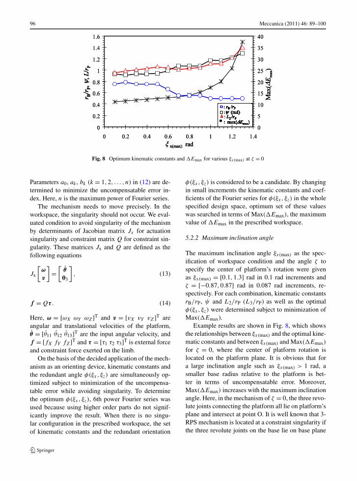
Fig. 8 Optimum kinematic constants and �Emax for various ξx(max) at ζ = 0
Parameters a0, ak , bk (k = 1,2, . . . , n) in (12) are de-termined to minimize the uncompensatable error in-dex. Here, n is the maximum power of Fourier series.
The mechanism needs to move precisely. In theworkspace, the singularity should not occur. We eval-uated condition to avoid singularity of the mechanismby determinants of Jacobian matrix Jx for actuationsingularity and constraint matrix Q for constraint sin-gularity. These matrices Jx and Q are defined as thefollowing equations
Jx
[ω
v
]=
[θ
03
], (13)
f = Qτ . (14)
Here, ω = [ωX ωY ωZ]T and v = [vX vY vZ]T areangular and translational velocities of the platform,θ = [θ11 θ12 θ13]T are the input angular velocity, andf = [fX fY fZ]T and τ = [τ1 τ2 τ3]T is external forceand constraint force exerted on the limb.
On the basis of the decided application of the mech-anism as an orienting device, kinematic constants andthe redundant angle φ(ξx, ξz) are simultaneously op-timized subject to minimization of the uncompensa-table error while avoiding singularity. To determinethe optimum φ(ξx, ξz), 6th power Fourier series wasused because using higher order parts do not signif-icantly improve the result. When there is no singu-lar configuration in the prescribed workspace, the setof kinematic constants and the redundant orientation
φ(ξx, ξz) is considered to be a candidate. By changingin small increments the kinematic constants and coef-ficients of the Fourier series for φ(ξx, ξz) in the wholespecified design space, optimum set of these valueswas searched in terms of Max(�Emax), the maximumvalue of �Emax in the prescribed workspace.
5.2.2 Maximum inclination angle
The maximum inclination angle ξx(max) as the spec-ification of workspace condition and the angle ζ tospecify the center of platform’s rotation were givenas ξx(max) = [0.1,1.3] rad in 0.1 rad increments andζ = [−0.87,0.87] rad in 0.087 rad increments, re-spectively. For each combination, kinematic constantsrB/rP, ψ and L2/rP (L3/rP) as well as the optimalφ(ξx, ξz) were determined subject to minimization ofMax(�Emax).
Example results are shown in Fig. 8, which showsthe relationships between ξx(max) and the optimal kine-matic constants and between ξx(max) and Max(�Emax)
for ζ = 0, where the center of platform rotation islocated on the platform plane. It is obvious that fora large inclination angle such as ξx(max) > 1 rad, asmaller base radius relative to the platform is bet-ter in terms of uncompensatable error. Moreover,Max(�Emax) increases with the maximum inclinationangle. Here, in the mechanism of ζ = 0, the three revo-lute joints connecting the platform all lie on platform’splane and intersect at point O. It is well known that 3-RPS mechanism is located at a constraint singularity ifthe three revolute joints on the base lie on base plane

Meccanica (2011) 46: 89–100 97
Fig. 9 Optimum kinematic constants and �Emax for various ζ .
and intersect at a point [16]. Referring to this example,the 3-URU mechanism of ζ = 0 might be consideredto be singular. However, as reported in (6), singularityof this mechanism is defined by geometrical relation-ship of the joint axes of all limbs not only by that ofthe three revolute joints on platform, and the mech-anism of ζ = 0 is not structurally singular. This willbe numerically shown below by using determinant ofmatrix Q.
5.2.3 Location of center of rotation of platform
The location of the center of rotation of the platformis considered for the application. Results of the sets ofoptimum kinematic constants with respect to location
of the center of rotation of the platform and the un-compensatable error are shown in Fig. 9 in which theresults for two cases of the maximum inclination angleξx(max) are shown. From Fig. 9(a), in which the max-imum inclination angle is given as ξx(max) = 0.6 rad,we can see that there are some range of ζ by whichMax(�Emax) is kept within a small range. This is thecase for −0.4 ≤ ζ ≤ 0.4 rad. On the other hand, fora larger inclination angle such as ξx(max) = 1.3 rad,shown in Fig. 9(b), we can see that there is little rangeof ζ that gives a small Max(�Emax). By increasingthe angle ζ , the error index increases rapidly. Thus, wealso found that the best choice for ξx(max) = 1.3 rad isζ = 0.

98 Meccanica (2011) 46: 89–100
Fig. 10 Optimum mechanism for ξx(max) = 1.3 rad
5.3 Optimum mechanism for special designspecification
We obtained an optimum mechanism which meets thedesign specifications given in Subsect. 5.1 by using thecharts for design shown in Figs. 8 and 9 and by fol-lowing the six design steps mentioned in Sect. 4. Weshow the result for the case of ξx(max) = 1.3 rad. Thekinematic diagram of the optimum mechanism and itsprototype are shown in Figs. 10 and 11, respectively.The prototype manipulator achieved a large inclinationangle ξx = 1.13 rad.
Determinants of Jacobian matrix, Jx and constraintmatrix, Q of the synthesized mechanism are shownin Fig. 12 where the optimal solution of redundantorientation angle φ(ξx, ξz) is used. From Fig. 12(a),it can be seen that using such an optimized φ, thereare no changes of sign of the determinant. It meansthat the mechanism does not pass through any actua-tion singular configurations. As for the constraint sin-gularity, plot of the determinant of constraint matrix,Q is shown in Fig. 12(b), which indicates the abilityof the mechanism to support external force. As shownin the figure, using such solution, the stiffness of themechanism increases by increasing the inclination an-gle, ξx .
Plots of the φ(ξx, ξz) are shown in Fig. 13. Fora lower inclination angle, φ(ξx, ξz) does not vary somuch with respect to ξx and ξz.
Plots of performance of the mechanism using theoptimized φ are shown in Fig. 14. From the figure,
Fig. 11 Prototype of optimum mechanism
the normalized error index �Emax/(rP�θV) reachesits maximum of 37.5 at ξx = 1.3 rad. From the trendof error index in the figure, it is known that the errorincreases by increasing the inclination angle.
6 Conclusions
We implemented a kinematic design of 3-URU purerotational parallel mechanism with a large workspacesubject to minimization of the position error of thecenter of platform rotation. Results are summarized asfollows.

Meccanica (2011) 46: 89–100 99
Fig. 12 Changes of detJx and detQ
(1) Optimal kinematic constants and the magnitude ofthe position error of the center of platform rotationfor the design specification in the maximum incli-nation angle of the platform have been clarified.The result was summarized in some charts that areuseful in kinematic design.
(2) By using the charts in (1), we found that the cen-ter of platform rotation should be located on theplatform plane to provide a large maximum incli-nation angle. On the other hand, the center of plat-form rotation can be chosen within some rangeby considering the application of the mechanismneeded for a small maximum inclination angle.
Fig. 13 Plots of optimum φ(ξx, ξz)
Fig. 14 Plots of error index, �Emax with optimum φ(ξx, ξz)
(3) An optimal design result and a prototype areshown for an orienting device of a machine toolwhich can achieve a large maximum inclinationangle such as 1.3 rad on the basis of the resultsmentioned above.
Acknowledgements This work was supported in part by aGrant-in-Aid for Scientific Research from the Ministry of Ed-ucation, Culture, Sports, Science and Technology (19560136).
References
1. Caro S, Wenger P, Bennis F, Chablat D (2006) Sen-sitivity analysis of the orthogride: A three-dof transla-

100 Meccanica (2011) 46: 89–100
tional parallel kinematic machine. Trans ASME J MechDes 128:392–402
2. Carretero JA, Podhorodeski RP, Nahon MA, Gosselin CM(2000) Kinematic analysis and optimization of a newthree degree-of-freedom spatial parallel manipulator. TransASME J Mech Des 122:17–24
3. Gao F, Li W, Zhao X, Jin Z, Zhao H (2002) New kinematicstructures for 2-, 3-, 4-, and 5-DOF parallel manipulatordesign. Mech Mach Theory 37:1395–1411
4. Han C, Kim J, Kim J, Park FK (2002) Kinematic sensitiv-ity of the 3-UPU parallel mechanism. Mech Mach Theory37:787–798
5. Huang T, Li M, Li Z, Chewynd DG, Whithouse DJ (2004)Optimal kinematic design of 2-DOF parallel manipulatorswith well-shaped workspace bounded by a specified condi-tion index. IEEE Trans Robot Autom 20:538–543
6. Huda S, Takeda Y (2007) Kinematic analysis and synthesisof a 3-URU pure rotational parallel mechanism with respectto singularity and workspace. J Adv Mech Des Syst Manuf1:81–92
7. Huda S, Takeda Y (2008) Kinematic desing of 3-URU purerotational parallel mechanism with consideration of the un-compensatable error. In: Proceedings of robotic symposia,Kotohira, Japan, pp 504–509
8. Liu X-J, Jin Z-L, Gao F (2000) Optimum design of 3-DOF spherical parallel manipulators with respect to theconditioning and stiffness indices. Mech Mach Theory35:1257–1267
9. Liu X-J, Wang J, Pritschow G (2006) On the optimal kine-matic design of the PRRRP-2 DoF parallel mechanism.Mech Mach Theory 41:1111–1130
10. Monsarrat B, Gosselin CM (2003) Workspace analysis andoptimal design of a 3-Leg 6-DOF parallel platform mecha-nism. IEEE Trans Robot Autom 6:954–966
11. Stamper RE, Tsai L-W, Walsh GC (1997) Optimiza-tion of a three DOF translational platform for well-condition workspace. In: Proceeding of the 1997 IEEEint. conference on robotics and automation, New Mexico,pp 3250–3255
12. Takeda Y, Funabashi H (1999) Kinematic synthesis ofin-parallel actuated mechanism based on global isotropyindex. J Robot Mechatronics 11:404–410
13. Takeda Y, Funabashi H (2001) A transmission index forin-parallel wire-driven mechanism. JSME Int J Ser C44:180–188
14. Vananzi S, Parenti-Castelli V (2005) A new technique forclearance influence analysis in spatial mechanisms. TransASME J Mech Des 127:446–455
15. Zhao J-S, Zhang S-L, Dong J-X, Feng Z-J, Zhou K (2007)Optimizing the kinematic chains for a spatial parallel ma-nipulator via searching the desired dexterous workspace.Robot Comput-Integr Manuf 23:38–46
16. Zlatanov D, Bonev IA, Gosselin CM (2002) Constraintsingularities of parallel mechanisms. In: Proceedings of theIEEE international conference on robotics and automation,pp 496–502