Kinematics and Workspace Analysis of Protein Based Nano-Actuators
10
G. Sharma Department of Mechanical and Industrial Eng., Northeastern University, 360 Huntington Ave., Boston, MA 02115 M. Badescu Jet Propulsion Laboratory (JPL), MS 67-119, 4800 Oak Grove Drive, Pasadena, CA 91109-8099 A. Dubey Department of Mechanical and Industrial Eng., Northeastern University, 360 Huntington Ave., Boston, MA 02115 and Department of Mechanical and Aerospace Eng., Rutgers University, 98 Brett Road, Piscataway, NJ 08854 C. Mavroidis 1 Department of Mechanical and Industrial Eng., Northeastern University, 360 Huntington Ave., Boston, MA 02115 S. M. Tomassone Department of Chemical and Biochemical Eng., Rutgers University, 98 Brett Road, Piscataway, NJ 08854 M. L. Yarmush Department of Biomedical Eng., Rutgers University, 617 Bowser Road, Piscataway, NJ 08854 Kinematics and Workspace Analysis of Protein Based Nano-Actuators In this paper, a novel nanoscale protein based nano actuator concept is described. Mo- lecular kinematic computational tools are developed and included in our Matlab Bioki- nematics Toolbox to study the protein nanomotor’s performance using geometric criteria. The computational tools include the development of the molecular motor direct and inverse kinematics using the protein’s Denavit and Hartenberg parameters and the cor- responding homogeneous transformation matrices. Furthermore, the workspace calcula- tion and analysis of the protein motor is performed. DOI: 10.1115/1.1900751 1 Introduction The recent explosion of research in nanotechnology, combined with important advances in molecular biology has created a new interest in biomolecular machines and robots 1,2. The first goal in the biomolecular machine development is to use various bio- logical elements—whose function at the cellular and sub-cellular level creates a motion, force, or a signal—as machine components that perform the same function in response to the same biological stimuli but in an artificial setting. In this way proteins and DNA could act as motors, mechanical joints, transmission elements, or sensors. If all these different components were assembled together they could potentially form nanodevices with multiple degrees of freedom, able to apply forces and manipulate objects in the nanos- cale world, transfer information from the nano to the macroscale world and even travel in a nanoscale environment 3. Just as conventional macro-machines are used to develop forces and motions to accomplish specific tasks, bio-nano-machines can be used to manipulate nano-objects, to assemble and fabricate other machines or products and to perform maintenance, repair and inspection operations. The potential advantages in developing bio-nano-machines include: a Energy efficiency due to their in- termolecular and interatomic interactions; b low maintenance needs and high reliability due to the lack of wear and also due to nature’s homeostatic mechanisms self-optimization and self- adaptation; and c low cost of production due to their small size and natural existence. Figure 1a shows one such concept of a nano-organism, with its “feet” made of helical peptides and its body using carbon nanotubes while the power unit is a biomolecu- lar motor. Figure 1b shows an example of a biomolecular nano- robot repairing an infected cell in a blood vessel. In this project, we are studying the development of a novel type of protein based motors called viral protein linear VPL nano- actuators. In order to infect new cells, several viruses employ proteins on their surface that undergo dramatic changes in their structural conformation in order to promote the fusion of the viral membrane with the cellular membrane. This change is due to the pH change associated with the vicinity of the cell 4. Given simi- lar conditions in an artificial setting, we are trying to create a pH controlled repeatable motion of these viruses and use them as nano-motors to power the joints of future bionanorobotic systems. The project consists of both computational and experimental tasks that aim to demonstrate the concept of the VPL nano-actuator and estimate its performance characteristics. In this paper we present results from the computational studies related to molecular kine- matics. The computational studies aim at developing models that can be used in understanding the mechanism of the proposed bionano motor, in predicting its feasibility and performance in terms of energy, force, speed, and other kinematic and dynamic criteria as well as perform optimal design procedures to identify protein se- 1 Corresponding Author. Telephone: 617 373-4121; Fax 617 373-2921. Email [email protected] Contributed by the Mechanisms and Robotics Committee for publication in the JOURNAL OF MECHANICAL DESIGN. Manuscript received September 15, 2004; revised February 25, 2005. Associate Editor: Thomas R. Chase. 718 / Vol. 127, JULY 2005 Copyright © 2005 by ASME Transactions of the ASME
-
Upload
independent -
Category
Documents
-
view
0 -
download
0
Transcript of Kinematics and Workspace Analysis of Protein Based Nano-Actuators
G. SharmaDepartment of Mechanical and Industrial Eng.,Northeastern University, 360 Huntington Ave.,
Boston, MA 02115
M. BadescuJet Propulsion Laboratory (JPL), MS 67-119,
4800 Oak Grove Drive,Pasadena, CA 91109-8099
A. DubeyDepartment of Mechanical and Industrial Eng.,Northeastern University, 360 Huntington Ave.,
Boston, MA 02115 and Department ofMechanical and Aerospace Eng., Rutgers
University, 98 Brett Road, Piscataway, NJ 08854
C. Mavroidis1
Department of Mechanical and Industrial Eng.,Northeastern University, 360 Huntington Ave.,
Boston, MA 02115
S. M. TomassoneDepartment of Chemical and Biochemical Eng.,
Rutgers University, 98 Brett Road,Piscataway, NJ 08854
M. L. YarmushDepartment of Biomedical Eng., Rutgers
University, 617 Bowser Road,Piscataway, NJ 08854
Kinematics and WorkspaceAnalysis of Protein BasedNano-ActuatorsIn this paper, a novel nanoscale protein based nano actuator concept is described. Mo-lecular kinematic computational tools are developed and included in our Matlab Bioki-nematics Toolbox to study the protein nanomotor’s performance using geometric criteria.The computational tools include the development of the molecular motor direct andinverse kinematics using the protein’s Denavit and Hartenberg parameters and the cor-responding homogeneous transformation matrices. Furthermore, the workspace calcula-tion and analysis of the protein motor is performed. �DOI: 10.1115/1.1900751�
1 IntroductionThe recent explosion of research in nanotechnology, combined
with important advances in molecular biology has created a newinterest in biomolecular machines and robots �1,2�. The first goalin the biomolecular machine development is to use various bio-logical elements—whose function at the cellular and sub-cellularlevel creates a motion, force, or a signal—as machine componentsthat perform the same function in response to the same biologicalstimuli but in an artificial setting. In this way proteins and DNAcould act as motors, mechanical joints, transmission elements, orsensors. If all these different components were assembled togetherthey could potentially form nanodevices with multiple degrees offreedom, able to apply forces and manipulate objects in the nanos-cale world, transfer information from the nano to the macroscaleworld and even travel in a nanoscale environment �3�.
Just as conventional macro-machines are used to develop forcesand motions to accomplish specific tasks, bio-nano-machines canbe used to manipulate nano-objects, to assemble and fabricateother machines or products and to perform maintenance, repairand inspection operations. The potential advantages in developingbio-nano-machines include: �a� Energy efficiency due to their in-termolecular and interatomic interactions; �b� low maintenance
1Corresponding Author. Telephone: �617� 373-4121; Fax �617� 373-2921. [email protected]
Contributed by the Mechanisms and Robotics Committee for publication in theJOURNAL OF MECHANICAL DESIGN. Manuscript received September 15, 2004; revised
February 25, 2005. Associate Editor: Thomas R. Chase.718 / Vol. 127, JULY 2005 Copyright © 20
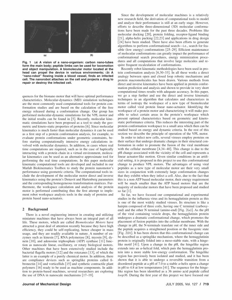
needs and high reliability due to the lack of wear and also due tonature’s homeostatic mechanisms �self-optimization and self-adaptation�; and �c� low cost of production due to their small sizeand natural existence. Figure 1�a� shows one such concept of anano-organism, with its “feet” made of helical peptides and itsbody using carbon nanotubes while the power unit is a biomolecu-lar motor. Figure 1�b� shows an example of a biomolecular nano-robot repairing an infected cell in a blood vessel.
In this project, we are studying the development of a novel typeof protein based motors called viral protein linear �VPL� nano-actuators. In order to infect new cells, several viruses employproteins on their surface that undergo dramatic changes in theirstructural conformation in order to promote the fusion of the viralmembrane with the cellular membrane. This change is due to thepH change associated with the vicinity of the cell �4�. Given simi-lar conditions in an artificial setting, we are trying to create a pHcontrolled repeatable motion of these viruses and use them asnano-motors to power the joints of future bionanorobotic systems.The project consists of both computational and experimental tasksthat aim to demonstrate the concept of the VPL nano-actuator andestimate its performance characteristics. In this paper we presentresults from the computational studies related to molecular kine-matics.
The computational studies aim at developing models that canbe used in understanding the mechanism of the proposed bionanomotor, in predicting its feasibility and performance in terms ofenergy, force, speed, and other kinematic and dynamic criteria as
well as perform optimal design procedures to identify protein se-05 by ASME Transactions of the ASME
quences for the bionano motor that will have optimal performancecharacteristics. Molecular-dynamics �MD� simulation techniquesare the most commonly used computational tools for protein con-formation studies and are based on the calculation of the freeenergy released during a conformation change. Our group hasperformed molecular-dynamic simulations for the VPL motor andthe initial results can be found in �5�. Recently, molecular kine-matic simulations have been proposed as a tool to study the geo-metric and kineto-static properties of proteins �6�. Since molecularkinematics is much faster than molecular dynamics it can be usedas a first step of a protein conformation analysis, for example, toevaluate protein conformations under geometric constraints, be-fore starting computationally intensive energy calculations in-volved with molecular dynamics. In addition, in cases where realtime computations are required, such as in the case of hapticallyinteracting with a protein chain in a virtual environment, molecu-lar kinematics can be used as an alternative approximate tool forperforming the real time computations. In this paper molecularkinematic computational tools are developed and included in ourMatlab Biokinematics Toolbox to study the protein nanomotor’sperformance using geometric criteria. The computational tools in-clude the development of the molecular motor direct and inversekinematics using the protein’s Denavit and Hartenberg parametersand the corresponding homogeneous transformation matrices. Fur-thermore, the workspace calculation and analysis of the proteinmotor is performed contributing thus the first attempt to imple-ment robot workspace analysis tools in the study of proteins andprotein based nano-actuators.
2 BackgroundThere is a novel engineering interest in creating and utilizing
miniature machines that have always been an integral part of alllife. These motors, which are called Biomolecular Motors haveattracted a great deal of attention recently because they have highefficiency, they could be self-replicating, hence cheaper in massusage, and they are readily available in nature. A number of en-zymes such as kinesin �7�, RNA polymerase �8�, myosin �9�, dy-nein �10�, and adenosine triphosphate �ATP� synthase �11� func-tion as nanoscale linear, oscillatory, or rotary biological motors.Other machines that have been extensively studied include thebacterial flagella motors �12� and the rotaxanes �13�, of which thelatter is an example of a purely chemical motor. In addition, thereare compliance devices such as springlike proteins called fi-bronectin �14� and vorticellids �15� and synthetic contractile plantpolymers �16� ready to be used as machine components. In addi-tion to protein-based machines, several researchers are exploring
Fig. 1 „a… A vision of a nano-organism: carbon nano-tubesform the main body; peptide limbs can be used for locomotionand object manipulation. A biomolecular motor located at thehead can propel the device in various environments; „b… A“nano-robot” flowing inside a blood vessel, finds an infectedcell. The nanorobot attaches on the cell and projects a drug torepair or destroy the infected cell.
the use of DNA in nanoscale mechanisms �17–19�.
Journal of Mechanical Design
Since the development of molecular machines is a relativelynew research field, the derivation of computational tools to modeland analyze their performance is still at an early stage. However,efforts to describe three-dimensional �3D� molecular conforma-tions have been made for the past three decades. Problems likemolecular docking �20�, protein folding, receptor-ligand binding�21�, alpha-helix packing �22,23� and applications in drug design�24� have been studied. There have also been efforts to generatealgorithms to perform conformational search—i.e., search for fea-sible �low energy� conformations �25–29�. Efficient maintenanceof molecular conformations can greatly impact the performance ofconformational search procedures, energy minimization proce-dures and all computations that involve large molecules and re-quire frequent recalculation of conformations.
Recently robot kinematic methodologies have been used in pro-tein conformation analysis �6,30–33�. In all these works a directanalogy between open and closed loop robotic mechanisms andprotein macromolecules has been drawn. Various methods fromdirect and inverse kinematics have been applied in protein confor-mation prediction and analysis and shown to provide in very shortcomputational times results with adequate accuracy. In this paper,we go a step further and use the direct and inverse kinematictechniques in an algorithm that calculates and characterizes interms of isotropy the workspace of a new type of biomolecularmotor called viral protein linear nano-actuator. Identifying theworkspace of a protein motor and characterizing it will make pos-sible to select certain areas in the protein’s workspace whichpresent optimal characteristics based on geometric and kineto-static performance criteria. This reduces the interesting part of theprotein conformation workspace to a small area which then can bestudied based on energy and dynamic criteria. In the rest of thissection we describe the principle of operation of the VPL motor.
In order to infect new cells, several viruses employ proteins ontheir surface that undergo dramatic changes in their structural con-formation in order to promote the fusion of the viral membranewith the cellular membrane �4,34–40�. This change is due to thepH change associated with the vicinity of the cell and represents alinear actuator-like motion. Given similar conditions in an artifi-cial setting, it is proposed in this project to use this conformationalchange to produce VPL motors. The advantages of using viralpeptides as a new type of molecular motor are their very smallsizes in conjunction with extremely large conformation changesthat they exhibit when they infect a cell. Also, due to the fact thatthis is a non-ATP based molecular motor, their energy requirementwill be much smaller than the ATP based motors that are themajority of molecular motors that have been proposed and studiedso far �1�.
So far, we have focused our computational and experimentalstudies in the influenza virus and its hemagglutinin protein as thisis one of the most widely studied viruses. Its structure is like ahairpin composed of three coils, having one C terminal �carboxy-end� and the other N terminal �amino-end� �Fig. 2�a��. As the pHof the viral containing vesicle drops, the hemagglutinin proteinundergoes a dramatic conformational change, which promotes theplacement of fusion peptides into the cellular membrane. With thechange in pH, the N-terminals translate out of the inner side andthe peptide acquires a straightened position or the fusogenic state�Fig. 2�b��. It has been shown that this conformational change canbe described as a springlike mechanism, where the hemagglutininprotein is originally folded into a meso-stable state, with a hinge-like motif �41�. Upon a change in the pH, the hingelike regionextends into an �-helical fold, which puts the hemagglutinin pro-tein into a more stable low-energy conformation. The hingelikeregion has previously been isolated and studied, and it has beenshown that it is able to undergo a reversible transition from adisordered peptide at a pH of 7.0 to a stable �-helix upon a changein pH to 4.8 at low temperatures �41�. The sequence for the hinge-like region has been identified as a 36 amino acid peptide called
loop36. During the first year of this project we have focused ourJULY 2005, Vol. 127 / 719

studies on the loop36 that has a closed length of about 4 nm andan extended length of about 6 nm, giving it an extension by twothirds of its length. These distances are measurable when the Pro-tein Data Bank �PDB� �42� structure files are visualized using anycapable program such as VMD �43�.
3 Molecular KinematicsMolecular kinematic simulations are being developed to study
the geometric properties and conformational space of the VPLactuators. The kinematic analysis is based on the development ofdirect and inverse kinematic models and their use towards theworkspace analysis of the VPL actuators. In this section wepresent the derivation of the direct and inverse kinematic modulesthat have been incorporated into a MATLAB toolbox called BioKi-neLab that has been developed in our laboratory to study proteinkinematics.
Proteins are heteropolymers made up of 20 different types ofamino acids, also called residues. The residues are connected to-gether one after the other in the form of a linear chain to make aprotein chain. For kinematics purpose we consider these residuesto be connected in a serial manner to create a serial manipulator.This is a common procedure in molecular kinematics of proteins�6,30–33�. The “back bone” of the chain is a repeat of theNitrogen–Alpha Carbon–Carbon �–N–C�–C–� sequence. To theC� atom is also attached a side-chain �R� which is different foreach residue. These side-chains are passive 3D structures with norevolute joints. Hydrogen atoms are neglected because of theirsmall size and weight as compared to the carbon and nitrogenatoms. Because of its chemical characteristic of having a partialdouble bond, the C–N bond of a protein chain is very rigid anddoes not allow any free rotation around it. There are, however,two bonds which are free to rotate. These are the N–C� andC�–C bonds and the rotation angles around them are known asphi ��� and psi ���, respectively �Fig. 3�. The value of theseangles determines the 3D structure of the protein and makes itperform its function. In most kinematic studies, bond lengths andbond angles are considered constant, while the torsional angles ��and �� are allowed to change �6,24,30–33�.
3.1 Direct Kinematics. The direct kinematics problem calcu-
Fig. 2 „a… Graphical representation of the initial state ofLoop36 region of VPL Actuator. The structure resembles threeinverted hairpins with inner regions �-helical but outer regionsare in a random loop configuration; „b… Low pH induced activeconformation of the same trimer. The random loop region con-verts into an �-helical region and the bent hairpin structurestraightens out producing a linear motion.
lates the VPL actuator’s final configuration when an initial con-
720 / Vol. 127, JULY 2005
figuration is given, all constant parameters of the chain are speci-fied and a specific set of rotations for the torsional angles isdefined. Frames are affixed at each backbone atom �Fig. 4�. Let bibe a bond between atoms Qi and Qi−1. A local frame Fi−1= �Qi−1 ;xi−1 ,yi−1 ,zi−1� is attached at bond bi−1 as follows: zi−1 hasthe direction of bond bi−1; xi−1 is perpendicular to both bi−1 and bi;and yi−1 is perpendicular to both xi−1 and zi−1 �Fig. 4�. Similarly,a local frame Fi= �Qi ;xi ,yi ,zi� is attached to bond bi�30�. Theprotein Denavit–Hartenberg �PDH� parameters are defined to fa-cilitate the geometric representation of one frame to another �44�as follows:
ai is the distance from zi−1 to zi measured along xi−1 and physi-cally represents the perpendicular distance between two succes-sive bonds;
�i is the angle between zi−1 and zi measured about xi−1 andrepresents the angle between two bonds;
bi is the distance from xi−1 to xi measured along zi; and repre-sents; the length of the bond joining Qi−1 to Qi;
�i is the angle between xi−1 and xi measured about zi and rep-resents the torsional angle of the bond.
The coordinates of the origin and of the unit vectors of frame Fiwith respect to frame Fi−1 are represented using the following 4�4 homogeneous transformation matrix �45� where c�i is thecos��i�, s�i is the sin��i�, c�i−1 is the cos��i−1�, and s�i−1 is thesin��i−1�.
Ri = �c�i − s�i 0 0
s�ic�i−1 c�i − c�i−1 − s�i−1 bis�i−1
s�is�i−1 c�is�i−1 − c�i−1 bic�i−1
0 0 0 1� �1�
Fig. 3 Rotational degrees of freedom along a residue chain.Adjacent residues are separated by dashed lines; side chainsare denoted by R, purple line represents the back-bone.
Fig. 4 Frames Fi−1 and Fi are attached to parent atom Qi−1 and
Qi and bond rotation angle is �i−1Transactions of the ASME
If an atom Qi is connected to the root atom Q0 by a sequence ofbonds bi , . . . ,b1, then the coordinates of Qi with respect to frameF0 are:
�x� y� z� 1�T = R1 · ¯ Ri · �0 0 0 1�T �2�In a similar way, the position of any atom on a side chain can be
calculated with the respect to the root frame F0.A representative result of the direct kinematics module of the
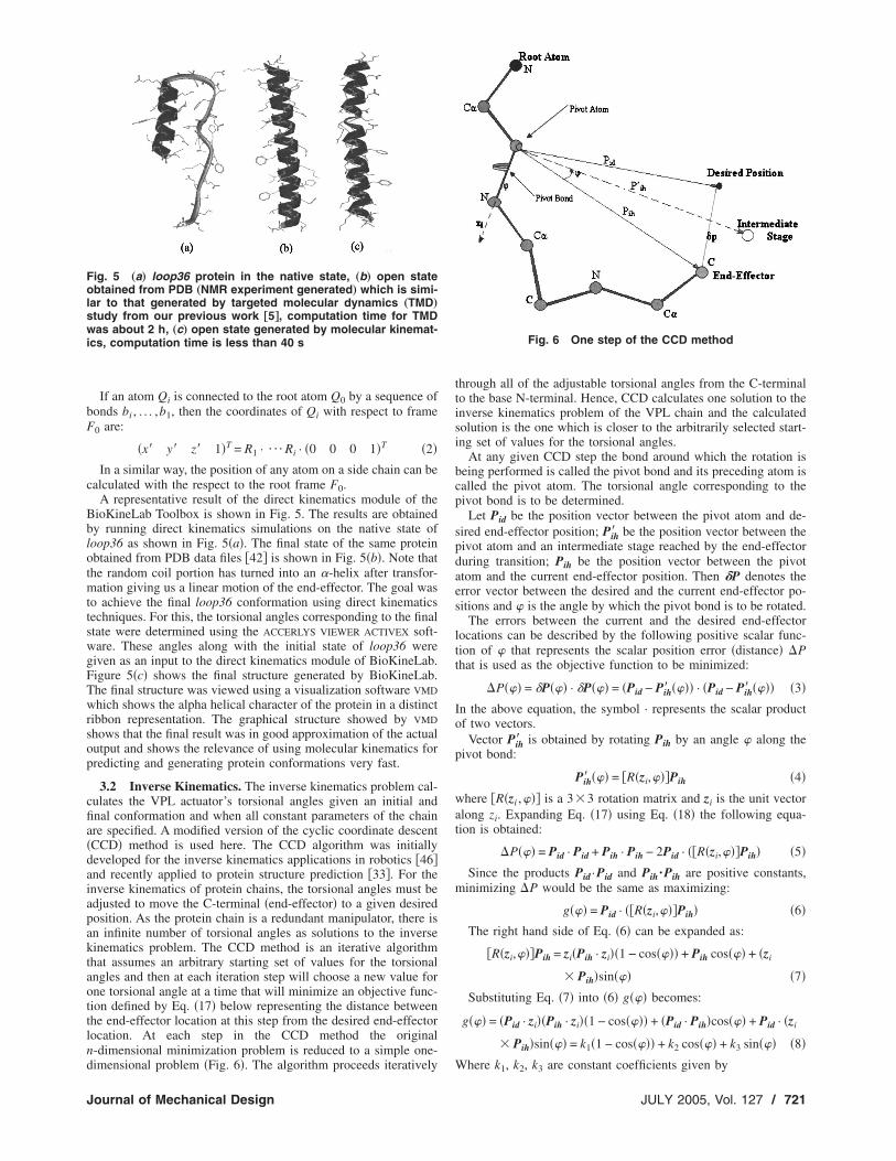
BioKineLab Toolbox is shown in Fig. 5. The results are obtainedby running direct kinematics simulations on the native state ofloop36 as shown in Fig. 5�a�. The final state of the same proteinobtained from PDB data files �42� is shown in Fig. 5�b�. Note thatthe random coil portion has turned into an �-helix after transfor-mation giving us a linear motion of the end-effector. The goal wasto achieve the final loop36 conformation using direct kinematicstechniques. For this, the torsional angles corresponding to the finalstate were determined using the ACCERLYS VIEWER ACTIVEX soft-ware. These angles along with the initial state of loop36 weregiven as an input to the direct kinematics module of BioKineLab.Figure 5�c� shows the final structure generated by BioKineLab.The final structure was viewed using a visualization software VMD
which shows the alpha helical character of the protein in a distinctribbon representation. The graphical structure showed by VMD
shows that the final result was in good approximation of the actualoutput and shows the relevance of using molecular kinematics forpredicting and generating protein conformations very fast.
3.2 Inverse Kinematics. The inverse kinematics problem cal-culates the VPL actuator’s torsional angles given an initial andfinal conformation and when all constant parameters of the chainare specified. A modified version of the cyclic coordinate descent�CCD� method is used here. The CCD algorithm was initiallydeveloped for the inverse kinematics applications in robotics �46�and recently applied to protein structure prediction �33�. For theinverse kinematics of protein chains, the torsional angles must beadjusted to move the C-terminal �end-effector� to a given desiredposition. As the protein chain is a redundant manipulator, there isan infinite number of torsional angles as solutions to the inversekinematics problem. The CCD method is an iterative algorithmthat assumes an arbitrary starting set of values for the torsionalangles and then at each iteration step will choose a new value forone torsional angle at a time that will minimize an objective func-tion defined by Eq. �17� below representing the distance betweenthe end-effector location at this step from the desired end-effectorlocation. At each step in the CCD method the originaln-dimensional minimization problem is reduced to a simple one-
Fig. 5 „a… loop36 protein in the native state, „b… open stateobtained from PDB „NMR experiment generated… which is simi-lar to that generated by targeted molecular dynamics „TMD…
study from our previous work †5‡, computation time for TMDwas about 2 h, „c… open state generated by molecular kinemat-ics, computation time is less than 40 s
dimensional problem �Fig. 6�. The algorithm proceeds iteratively
Journal of Mechanical Design
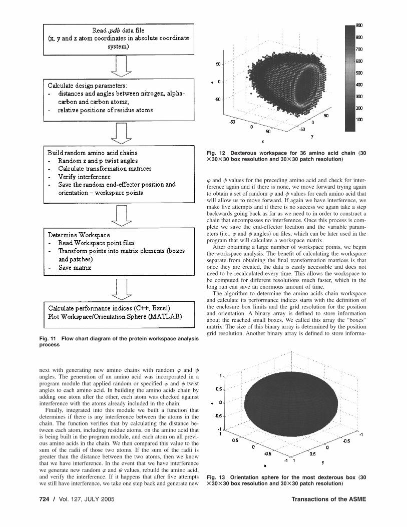
through all of the adjustable torsional angles from the C-terminalto the base N-terminal. Hence, CCD calculates one solution to theinverse kinematics problem of the VPL chain and the calculatedsolution is the one which is closer to the arbitrarily selected start-ing set of values for the torsional angles.
At any given CCD step the bond around which the rotation isbeing performed is called the pivot bond and its preceding atom iscalled the pivot atom. The torsional angle corresponding to thepivot bond is to be determined.
Let Pid be the position vector between the pivot atom and de-sired end-effector position; Pih� be the position vector between thepivot atom and an intermediate stage reached by the end-effectorduring transition; Pih be the position vector between the pivotatom and the current end-effector position. Then �P denotes theerror vector between the desired and the current end-effector po-sitions and � is the angle by which the pivot bond is to be rotated.
The errors between the current and the desired end-effectorlocations can be described by the following positive scalar func-tion of � that represents the scalar position error �distance� �Pthat is used as the objective function to be minimized:
�P��� = �P��� · �P��� = �Pid − Pih� ���� · �Pid − Pih� ���� �3�In the above equation, the symbol · represents the scalar productof two vectors.
Vector Pih� is obtained by rotating Pih by an angle � along thepivot bond:
Pih� ��� = �R�zi,���Pih �4�
where �R�zi ,��� is a 3�3 rotation matrix and zi is the unit vectoralong zi. Expanding Eq. �17� using Eq. �18� the following equa-tion is obtained:
�P��� = Pid · Pid + Pih · Pih − 2Pid · ��R�zi,���Pih� �5�
Since the products Pid ·Pid and Pih ·Pih are positive constants,minimizing �P would be the same as maximizing:
g��� = Pid · ��R�zi,���Pih� �6�The right hand side of Eq. �6� can be expanded as:
�R�zi,���Pih = zi�Pih · zi��1 − cos���� + Pih cos��� + �zi
� Pih�sin��� �7�
Substituting Eq. �7� into �6� g��� becomes:
g��� = �Pid · zi��Pih · zi��1 − cos���� + �Pid · Pih�cos��� + Pid · �zi
� Pih�sin��� = k1�1 − cos���� + k2 cos��� + k3 sin��� �8�
Fig. 6 One step of the CCD method
Where k1, k2, k3 are constant coefficients given by
JULY 2005, Vol. 127 / 721

k1 = �Pid · zi��Pih · zi�, k2 = Pid · Pih, k3 = zi · �Pih � Pid��9�
If there are no boundary constraints imposed on �, then g��� ismaximized if the following conditions are satisfied:
dg���d�
= �k1 − k2�sin��� + k3 cos��� = 0 �10�
d2g���d�2 = �k1 − k2�cos��� − k3 sin��� � 0 �11�
A unique value of � can be determined from these equations.From Eq. �10�, angle can be calculated:
� = tan−1 k3
k2 − k1 �12�
This determines a candidate value �c in the range − /2��c� /2. However, since function tan is periodic, there is poten-tially one other value to consider: �c+. Of these candidate val-ues, those which pass the second derivative test in inequality �11�are the maximizing values for the objective function �3�. If there ismore than one value, the objective function is evaluated with eachof them to determine which yields the true maximum.
Once � has been uniquely determined this way the correspond-ing pivot bond is rotated to reflect the change and the end-effectorposition is computed using direct kinematics techniques and theCCD method proceeds to the next iteration. Figure 7 is the balland stick model of a segment of the protein before and after theinverse kinematics simulation. Side chains are not shown for clar-ity. Table 1 shows the inverse kinematics results of the CCD simu-lations.
4 Workspace AnalysisThis section presents the methodology to determine the work-
space of an amino acid protein chain. The methodology starts byreading the data from a protein data bank �PDB� file and deter-mining the design parameters. A random process of building newamino acid chains and determining the end-effector position andorientation is repeated a large number of times. In the buildingprocess the interference between atoms is verified, and the con-
Fig. 7 Initial conformation of the protein „left… and one of thesolutions found by CCD simulations „right…
Table 1 Results of inverse kinematics with Loop36
X �� Y �� Z ��
End-effector initial position 23.3 81.7 228.0Desired position 26.0 75.0 224.0Position reached 26.0 74.8 223.9
Error �� 0.1566Number of iterations 31
722 / Vol. 127, JULY 2005
figurations where the interference occurs are eliminated fromamong the good configurations. The workspace points are savedin a matrix and performance indices are calculated. Here resultsare presented in table and graphic forms.
4.1 Mathematical Tools. This section defines the perfor-mance indices used in this work to perform the workspace char-acterization of the amino acid protein chains. These indices are thesame as the ones that we used in our previous work for workspacecharacterization of the modular hyper-redundant robotic arms�47�. In this section we only present the fundamental terms andconcepts associated with our method and the details of the methodcan be found in our previous work in �47�.
Figure 8 shows a point denoted by the symbol “x,” in the work-space of an amino acid protein chain that can be reached by twoor more configurations �Configurations 1 and 2�. A service sphereis defined around the point. The end-effector of an amino acidprotein chain would reach that point in more than one configura-tion and intersect the service sphere in more than one point. Thepoints where the end-effector axis intersects the service sphere arecalled service points. The set of all service points on the sphereform a service region. The dexterous solid angle, D�x�, is definedas the ratio of the total area of the service regions, AR�x�, to thearea of the service sphere, AS, at the point x of the end-effector.
D�x� =AR�x�
AS=
AR�x�4r2 �13�
where r is the radius of the service sphere.Since the dexterous solid angle of kinematic chains is not de-
fined by a continuous function, numerical methods are used tocalculate its integral. The procedure starts with defining an enclo-sure box that includes all the workspace points. The enclosure boxcan be initially a cube with the length of the edge double themaximum length of the protein. The program can be run oncewith a lower resolution and determine the actual limits of theworkspace and then use those limits to define the enclosure box.The enclosure box is divided into Nx�Ny �Nz equal volumeboxes small boxes. Figure 9 shows the enclosure box and one ofthe small boxes. Nx is the number of boxes on the side of theenclosure box parallel with x coordinate axis, Ny is the number of
Fig. 8 The dexterous solid angle
Fig. 9 Enclosure box
Transactions of the ASME

boxes on the side of the enclosure box parallel with the y axis, andNz is the number of boxes on the side of the enclosure box parallelwith the z axis.
For each small box, an orientation sphere of unit radius is de-fined and divided into P�Q equal area patches, in latitude andlongitude �see Fig. 10�. P is the number of strips in longitude andQ in the number of strips in latitude. The values of P and Q aredetermined by the orientation resolution that you want to achievefor a patch that is positioned at the “Equator” of the orientationsphere. For example, for a 4°�4° resolution you need P=90 stripsin longitude and Q=45 strips in latitude. The strips are equallyspaced in longitude. The angles at which the sphere is divided intostrips in latitude are defined by Eq. �14�, which is derived from thecondition that the area of each patch is 1 / �P*Q� of the total areaof the sphere.
�i = arccos�1 −2i
Q�, where i = 0 . . Q �14�
Figure 10 shows an example of a low-resolution orientationsphere. The filled patches will be later used to represent patchesthat can be reached by the end-effector.
The following performance indices are defined for the charac-terization of the workspace of amino acid protein chains and foreach one of them the numerical calculation method is outlined:
1� the workspace volume �VW� determines the volume of thespace that can be reached by the end-effector in at least one ori-entation. All linear dimensions are expressed in angstrom �A�, andso, the workspace volume is determined in cubic angstroms �A3�.The index is calculated as the sum of the volumes of the boxeswith at least one point reached by the end-effector or as the ratioof the reached boxes over the total number of boxes multipliedwith the volume of the enclosure box:
VW = v�W
dv �15a�
VW =K
Nx � Ny � NzVinitial �15b�
2� the dexterous workspace volume �VWD� shows how much ofthe reachable/workspace volume is also dexterous. It is defined asthe integration of the dexterous solid angle over the whole work-space volume. The index is calculated as the ratio of the numberof reached patches to the total number of patches in reached
Fig. 10 Orientation sphere
boxes, multiplied with the workspace volume:
Journal of Mechanical Design
VWD = v�W
D�x�dv �16a�
VWD =�i=1
KDi
K � P � Q� Vw �16b�
3� the dexterity index �ID� shows what percentage of the reach-able volume is also dexterous. The index is calculated as the ratioof the number of reached patches over the total number of patchesin reached boxes multiplied with 100:
ID =�i=1
KDi
K � P � Q� 100�%� �17�
4� the workspace volume with a certain dexterity �Vi� is definedas the volume of the space where the dexterous solid angle has atleast a certain value. The index is calculated as the ratio of thenumber of boxes with at least Ki reached patches over the totalnumber of boxes in the enclosure box, multiplied with the volumeof the enclosure box. It can also be defined in index form as apercentage of the number of boxes with certain dexterity out ofthe total number of boxes reached by the end-effector. In thiswork three values for the number of patches Ki �i=100, 500, and1000� were considered:
V100 =K100
Nx � Ny � Nz� Vinitial �18a�
V500 =K500
Nx � Ny � Nz� Vinitial �18b�
V1000 =K1000
Nx � Ny � Nz� Vinitial �18c�
where,K is the total number of boxes reached by the end-effector;Di is the total number of patches in the box i reached by the
end-effector;K100 is the number of boxes in which the end-effector reached
at least 100 patches;K500 is the number of boxes in which the end-effector reached
at least 500 patches;K1000 is the number of boxes in which the end-effector reached
at least 1000 patches.
4.2 Method and Implementation. The process of determin-ing the workspace of a protein chain starts by taking the PDB�protein data bank� file and importing the data into structures inour program. The data are divided into two structures referred toin the program as atom and amino. The amino structure groupstogether the common atoms that make up a specific amino acidand the atom structure contained the information relevant to eachatom in the amino acid.
We assigned coordinate frames for each simple transformation�i.e., translation and rotation�. We studied the same 36 amino loopas in Sec. 3.1 but the coordinate frames were assigned differently.The base frame of each amino acid has the origin half way be-tween the C atom of the previous amino acid and the N atom ofthe current amino acid. The end-effector frame of each amino acidhas the origin half way between the C atom of current amino acidand the N atom of the next amino acid. By defining the frames inthis way we were able to reduce the number of “movable” framesfrom 36 to 34 and hence reduce the computation time of theworkspace analysis. In the analysis we considered variables thetwist angles of the N–C� and C�–C bonds, called � and �, andconstant all the other angles and the bond lengths. The atoms thatwere not part of the “back bone” were considered fixed in the
local frame of the atom that they were connected to. We continuedJULY 2005, Vol. 127 / 723
next with generating new amino chains with random � and �angles. The generation of an amino acid was incorporated in aprogram module that applied random or specified � and � twistangles to each amino acid. In building the amino acids chain byadding one atom after the other, each atom was checked againstinterference with the atoms already included in the chain.
Finally, integrated into this module we built a function thatdetermines if there is any interference between the atoms in thechain. The function verifies that by calculating the distance be-tween each atom, including residue atoms, on the amino acid thatis being built in the program module, and each atom on all previ-ous amino acids in the chain. We then compared this value to thesum of the radii of those two atoms. If the sum of the radii isgreater than the distance between the two atoms, then we knowthat we have interference. In the event that we have interferencewe generate new random � and � values, rebuild the amino acid,and verify the interference. If it happens that after five attempts
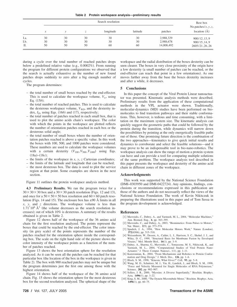
Fig. 11 Flow chart diagram of the protein workspace analysisprocess
we still have interference, we take one step back and generate new
724 / Vol. 127, JULY 2005
� and � values for the preceding amino acid and check for inter-ference again and if there is none, we move forward trying againto obtain a set of random � and � values for each amino acid thatwill allow us to move forward. If again we have interference, wemake five attempts and if there is no success we again take a stepbackwards going back as far as we need to in order to construct achain that encompasses no interference. Once this process is com-plete we save the end-effector location and the variable param-eters �i.e., � and � angles� on files, which can be later used in theprogram that will calculate a workspace matrix.
After obtaining a large number of workspace points, we beginthe workspace analysis. The benefit of calculating the workspaceseparate from obtaining the final transformation matrices is thatonce they are created, the data is easily accessible and does notneed to be recalculated every time. This allows the workspace tobe computed for different resolutions much faster, which in thelong run can save an enormous amount of time.
The algorithm to determine the amino acids chain workspaceand calculate its performance indices starts with the definition ofthe enclosure box limits and the grid resolution for the positionand orientation. A binary array is defined to store informationabout the reached small boxes. We called this array the “boxes”matrix. The size of this binary array is determined by the positiongrid resolution. Another binary array is defined to store informa-
Fig. 12 Dexterous workspace for 36 amino acid chain „30Ã30Ã30 box resolution and 30Ã30 patch resolution…
Fig. 13 Orientation sphere for the most dexterous box „30
Ã30Ã30 box resolution and 30Ã30 patch resolution…Transactions of the ASME

tion about the orientation patches in all the small boxes that arereached by the end-effector. We called this array the “workspacematrix.” The size of the workspace matrix is determined by theposition and orientation grid resolution. At the start of the pro-gram all the elements of the two arrays are initialized with 0�FALSE� values.
For each workspace point the origin of the end-effector is in asmall box and the orientation corresponds to an orientation patch.The element in the boxes matrix corresponding to the workspacesmall box that includes the end-effector’s position is marked ON.From the orientation of the end-effector �i.e., the orientation of the
Fig. 14 Dexterous workspace for 36 am60Ã60 patch resolution…
Fig. 15 Orientation sphere for the mos
tion and 60Ã60 patch resolution…Journal of Mechanical Design
z axis of the moving frame of the last module� the latitude andlongitude of the end-effector are determined. The element in theworkspace matrix corresponding to the orientation patch that in-cludes these latitude and longitude is marked ON. The algorithmof marking elements of the boxes and workspace matrices fromsuccessful protein configurations repeats for 200,000 times. Thenall the elements marked ON are counted.
The cycle of determining the elements of the two matrices froma set of new 200,000 random successful protein positions startsover. It stops when the ratio of the number of new added patches
chain „50Ã50Ã50 box resolution and
exterous box „50Ã50Ã50 box resolu-
ino
t d
JULY 2005, Vol. 127 / 725
during a cycle over the total number of reached patches dropsbelow a predefined relative value �e.g., 0.0002%�. From runningthe program for different protein configurations we observed thatthe search is actually exhaustive as the number of new foundpatches drops suddenly to zero after a big enough number ofcycles.
The program determines:
– the total number of small boxes reached by the end-effector.This is used to calculate the workspace volume, Vw, usingEq. �15b�;
– the total number of reached patches. This is used to calculatethe dexterous workspace volume, VWD, and the dexterity in-dex, ID, using Eqs. �16b� and �17�, respectively;
– the total number of patches reached in each small box, that isused to plot the amino acids chain’s workspace. The colorwith which the points in the workspace are plotted reflectsthe number of orientation patches reached in each box or thedexterous solid angle;
– the total number of small boxes where the number of orien-tation patches reached is above a specific value. In this workthe boxes with 100, 500, and 1000 patches were considered.These numbers are used to calculate the workspace volumeswith a certain dexterity �V100,V500,V1000� using Eqs.�18a�–�18c�;
– the limits of the workspace in x, y, z Cartesian coordinates;– the limits of the latitude and longitude that can be reached;– the most dexterous box. The data is used to plot the service
region at that point. Some examples are shown in the nextsection.
Figure 11 outlines the protein workspace analysis method.
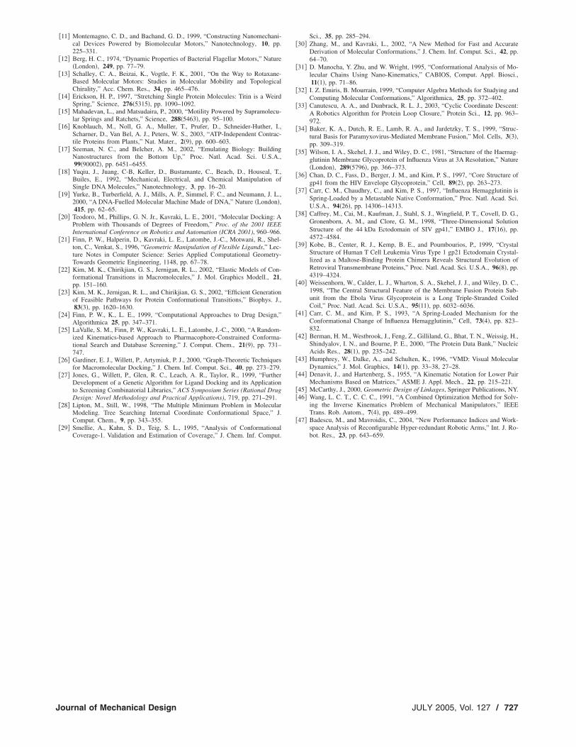
4.3 Preliminary Results. We ran the program twice for a30�30�30 box and a 30�30 patch resolution �Figs. 12 and 13�,and once for a 50�50�50 box resolution and 60�60 patch reso-lution �Figs. 14 and 15�. The enclosure box has ±90 Å limits in allx, y, and z directions. The workspace volume is less than1.71*106 Å3 �the volume decreases as the search resolution in-creases�; out of which 10% is dexterous. A summary of the resultsobtained is given in Table 2.
Figure 12 shows half of the workspace of the 36 amino acidchain for the first resolution analyzed. The points represent theboxes that could be reached by the end-effector. The color inten-sity �in grey scale� of the points represents the number of thepatches reached for the orientation sphere inside the correspond-ing box. The scale on the right hand side of the picture shows thecolor intensity of the workspace points as a function of the num-ber of patches reached.
Figure 13 shows the best orientation sphere for the resolutionanalyzed. As it can be seen all the patches can be reached for thatparticular box �the location of the box in the workspace is given inTable 2�. The box with 900 reached patches may not be unique butthe program determines just the first one among those with thehighest orientation.
Figure 14 shows half of the workspace of the 36 amino acidchain. Fig. 15 shows the orientation sphere for the most dexterous
Table 2 Protein workspace
Search resoluti
x y z longitude
I.a. 30 30 30 30I.b. 30 30 30 30II. 50 50 50 60
box for the second resolution analyzed. The spherical shape of the
726 / Vol. 127, JULY 2005
workspace and the radial distribution of the boxes dexterity can beseen clearer. The boxes in very close proximity of the origin havea low dexterity �a small number of patches can be reached, or theend-effector can reach that point in a few orientations�. As onemoves farther away from the base the boxes dexterity increasesand after a while, it decreases.
5 ConclusionsIn this paper the concept of the Viral Protein Linear nanoactua-
tor was presented. Kinematic analysis methods were described.Preliminary results from the application of these computationalmethods in the VPL actuator were shown. Traditionally,molecular-dynamics �MD� studies have been performed on bio-molecules to find transition pathways and their stable conforma-tions. This, however, is tedious and time consuming, with a limi-tation on the maximum system size. The kinematic analysis canquickly suggest the geometric paths that could be followed by theprotein during the transition, while dynamics will narrow downthe possibilities by pointing at the only energetically feasible pathsout of those. One promising future direction is the combination ofthe two approaches—kinematics to give quick initial results anddynamics to corroborate and select the feasible solutions—and itmay prove to be an indispensable tool in bio-nano-robotics. Theworkspace analysis can show the range of motion a protein systemcan have and can provide a tool for comparing multiple solutionsof the same problem. The workspace analysis tool described inthis paper presents the workspace and dexterity of the amino acidchain in different zones of the workspace.
AcknowledgmentsThis work was supported by the National Science Foundation
�DMI–0303950 and DMI-0422724�. Any opinions, findings, con-clusions or recommendations expressed in this publication arethose of the authors and do not necessarily reflect the views of theNational Science Foundation. The work of Kevin Nikitczuk inpreparing the illustrations used in this paper and of Tom Sessa inthe program development is acknowledged.
References�1� Mavroidis, C., Dubey, A., and Yarmush, M. L., 2004, “Molecular Machines,”
Ann. Biomed. Eng., 6, pp. 363–395.�2� Mavroidis, C., and Dubey, A., 2003, “Biomimetics: From Pulses to Motors,”
Nat. Mater., 2�9�, pp. 573–574.�3� Spudich, J. A., 1994, “How Molecular Motors Work,” Nature �London�,
372�6506�, pp. 515–518.�4� Weissenhorn, W., Dessen, A., Calder, L. J., Harrison, S. C., Skehel, J. J., and
Wiley, D. C., 1999, “Structural Basis for Membrane Fusion by EnvelopedViruses,” Mol. Membr Biol., 16�1�, pp. 3–9.
�5� Dubey, A., Sharma, G., Mavroidis, C., Tomassone, M. S., Nikitczuk, K., andYarmush, M. L., 2004, “Computational Studies of Viral Protein Nano-Actuator,” J. Theor. Comput. Nanosci., 1�1�, pp. 1–11.
�6� Kazerounian, K., 2004, “From Mechanisms and Robotics to Protein Confor-mation and Drug Design,” J. Mech. Des., 126, pp. 1–6.
�7� Block, S. M., 1998, “Kinesin, What Gives?” Cell, 93, pp. 5–8.�8� Wang, M. D., Schnitzer, M. J., Yin, H., Landick, J., and Block, S. M., 1998,
“Force and Velocity Measured for Single Molecules of RNA Polymerase,”Science, 282, pp. 902–907.
�9� Sellers, J. R., 2000, “Myosins: A Diverse Superfamily,” Biochim. Biophys.Acta, 1496�1�, pp. 3–22.
�10� King, S. M., 2000, “The Dynein Microtubule Motor,” Biochim. Biophys. Acta,
alysis—preliminary results
Best boxNo.patches/x ,y ,z,
location ��latitude patches
30 2,988,329 900/12,13,930 2,988,678 900/15,14,960 14,008,492 2605/21,26,26
an
on
1496�1�, pp. 60–75.
Transactions of the ASME
�11� Montemagno, C. D., and Bachand, G. D., 1999, “Constructing Nanomechani-cal Devices Powered by Biomolecular Motors,” Nanotechnology, 10, pp.225–331.
�12� Berg, H. C., 1974, “Dynamic Properties of Bacterial Flagellar Motors,” Nature�London�, 249, pp. 77–79.
�13� Schalley, C. A., Beizai, K., Vogtle, F. K., 2001, “On the Way to Rotaxane-Based Molecular Motors: Studies in Molecular Mobility and TopologicalChirality,” Acc. Chem. Res., 34, pp. 465–476.
�14� Erickson, H. P., 1997, “Stretching Single Protein Molecules: Titin is a WeirdSpring,” Science, 276�5315�, pp. 1090–1092.
�15� Mahadevan, L., and Matsudaira, P., 2000, “Motility Powered by Supramolecu-lar Springs and Ratchets,” Science, 288�5463�, pp. 95–100.
�16� Knoblauch, M., Noll, G. A., Muller, T., Prufer, D., Schneider-Huther, I.,Scharner, D., Van Bel, A. J., Peters, W. S., 2003, “ATP-Independent Contrac-tile Proteins from Plants,” Nat. Mater., 2�9�, pp. 600–603.
�17� Seeman, N. C., and Belcher, A. M., 2002, “Emulating Biology: BuildingNanostructures from the Bottom Up,” Proc. Natl. Acad. Sci. U.S.A.,99�90002�, pp. 6451–6455.
�18� Yuqiu, J., Juang, C-B, Keller, D., Bustamante, C., Beach, D., Houseal, T.,Builes, E., 1992, “Mechanical, Electrical, and Chemical Manipulation ofSingle DNA Molecules,” Nanotechnology, 3, pp. 16–20.
�19� Yurke, B., Turberfield, A. J., Mills, A. P., Simmel, F. C., and Neumann, J. L.,2000, “A DNA-Fuelled Molecular Machine Made of DNA,” Nature �London�,415, pp. 62–65.
�20� Teodoro, M., Phillips, G. N. Jr., Kavraki, L. E., 2001, “Molecular Docking: AProblem with Thousands of Degrees of Freedom,” Proc. of the 2001 IEEEInternational Conference on Robotics and Automation (ICRA 2001), 960–966.
�21� Finn, P. W., Halperin, D., Kavraki, L. E., Latombe, J.-C., Motwani, R., Shel-ton, C., Venkat, S., 1996, “Geometric Manipulation of Flexible Ligands,” Lec-ture Notes in Computer Science: Series Applied Computational Geometry-Towards Geometric Engineering, 1148, pp. 67–78.
�22� Kim, M. K., Chirikjian, G. S., Jernigan, R. L., 2002, “Elastic Models of Con-formational Transitions in Macromolecules,” J. Mol. Graphics Modell., 21,pp. 151–160.
�23� Kim, M. K., Jernigan, R. L., and Chirikjian, G. S., 2002, “Efficient Generationof Feasible Pathways for Protein Conformational Transitions,” Biophys. J.,83�3�, pp. 1620–1630.
�24� Finn, P. W., K., L. E., 1999, “Computational Approaches to Drug Design,”Algorithmica 25, pp. 347–371.
�25� LaValle, S. M., Finn, P. W., Kavraki, L. E., Latombe, J.-C., 2000, “A Random-ized Kinematics-based Approach to Pharmacophore-Constrained Conforma-tional Search and Database Screening,” J. Comput. Chem., 21�9�, pp. 731–747.
�26� Gardiner, E. J., Willett, P., Artymiuk, P. J., 2000, “Graph-Theoretic Techniquesfor Macromolecular Docking,” J. Chem. Inf. Comput. Sci., 40, pp. 273–279.
�27� Jones, G., Willett, P., Glen, R. C., Leach, A. R., Taylor, R., 1999, “FurtherDevelopment of a Genetic Algorithm for Ligand Docking and its Applicationto Screening Combinatorial Libraries,” ACS Symposium Series (Rational DrugDesign: Novel Methodology and Practical Applications), 719, pp. 271–291.
�28� Lipton, M., Still, W., 1998, “The Multiple Minimum Problem in MolecularModeling. Tree Searching Internal Coordinate Conformational Space,” J.Comput. Chem., 9, pp. 343–355.
�29� Smellie, A., Kahn, S. D., Teig, S. L., 1995, “Analysis of ConformationalCoverage-1. Validation and Estimation of Coverage,” J. Chem. Inf. Comput.
Journal of Mechanical Design
Sci., 35, pp. 285–294.�30� Zhang, M., and Kavraki, L., 2002, “A New Method for Fast and Accurate
Derivation of Molecular Conformations,” J. Chem. Inf. Comput. Sci., 42, pp.64–70.
�31� D. Manocha, Y. Zhu, and W. Wright, 1995, “Conformational Analysis of Mo-lecular Chains Using Nano-Kinematics,” CABIOS, Comput. Appl. Biosci.,11�1�, pp. 71–86.
�32� I. Z. Emiris, B. Mourrain, 1999, “Computer Algebra Methods for Studying andComputing Molecular Conformations,” Algorithmica, 25, pp. 372–402.
�33� Canutescu, A. A., and Dunbrack, R. L. J., 2003, “Cyclic Coordinate Descent:A Robotics Algorithm for Protein Loop Closure,” Protein Sci., 12, pp. 963–972.
�34� Baker, K. A., Dutch, R. E., Lamb, R. A., and Jardetzky, T. S., 1999, “Struc-tural Basis for Paramyxovirus-Mediated Membrane Fusion,” Mol. Cells, 3�3�,pp. 309–319.
�35� Wilson, I. A., Skehel, J. J., and Wiley, D. C., 1981, “Structure of the Haemag-glutinin Membrane Glycoprotein of Influenza Virus at 3A Resolution,” Nature�London�, 289�5796�, pp. 366–373.
�36� Chan, D. C., Fass, D., Berger, J. M., and Kim, P. S., 1997, “Core Structure ofgp41 from the HIV Envelope Glycoprotein,” Cell, 89�2�, pp. 263–273.
�37� Carr, C. M., Chaudhry, C., and Kim, P. S., 1997, “Influenza Hemagglutinin isSpring-Loaded by a Metastable Native Conformation,” Proc. Natl. Acad. Sci.U.S.A., 94�26�, pp. 14306–14313.
�38� Caffrey, M., Cai, M., Kaufman, J., Stahl, S. J., Wingfield, P. T., Covell, D. G.,Gronenborn, A. M., and Clore, G. M., 1998, “Three-Dimensional SolutionStructure of the 44 kDa Ectodomain of SIV gp41,” EMBO J., 17�16�, pp.4572–4584.
�39� Kobe, B., Center, R. J., Kemp, B. E., and Poumbourios, P., 1999, “CrystalStructure of Human T Cell Leukemia Virus Type 1 gp21 Ectodomain Crystal-lized as a Maltose-Binding Protein Chimera Reveals Structural Evolution ofRetroviral Transmembrane Proteins,” Proc. Natl. Acad. Sci. U.S.A., 96�8�, pp.4319–4324.
�40� Weissenhorn, W., Calder, L. J., Wharton, S. A., Skehel, J. J., and Wiley, D. C.,1998, “The Central Structural Feature of the Membrane Fusion Protein Sub-unit from the Ebola Virus Glycoprotein is a Long Triple-Stranded CoiledCoil,” Proc. Natl. Acad. Sci. U.S.A., 95�11�, pp. 6032–6036.
�41� Carr, C. M., and Kim, P. S., 1993, “A Spring-Loaded Mechanism for theConformational Change of Influenza Hemagglutinin,” Cell, 73�4�, pp. 823–832.
�42� Berman, H. M., Westbrook, J., Feng, Z., Gilliland, G., Bhat, T. N., Weissig, H.,Shindyalov, I. N., and Bourne, P. E., 2000, “The Protein Data Bank,” NucleicAcids Res., 28�1�, pp. 235–242.
�43� Humphrey, W., Dalke, A., and Schulten, K., 1996, “VMD: Visual MolecularDynamics,” J. Mol. Graphics, 14�1�, pp. 33–38, 27–28.
�44� Denavit, J., and Hartenberg, S., 1955, “A Kinematic Notation for Lower PairMechanisms Based on Matrices,” ASME J. Appl. Mech., 22, pp. 215–221.
�45� McCarthy, J., 2000, Geometric Design of Linkages, Springer Publications, NY.�46� Wang, L. C. T., C. C. C., 1991, “A Combined Optimization Method for Solv-
ing the Inverse Kinematics Problem of Mechanical Manipulators,” IEEETrans. Rob. Autom., 7�4�, pp. 489–499.
�47� Badescu, M., and Mavroidis, C., 2004, “New Performance Indices and Work-space Analysis of Reconfigurable Hyper-redundant Robotic Arms,” Int. J. Ro-bot. Res., 23, pp. 643–659.
JULY 2005, Vol. 127 / 727