KATRADIS VEP SA
13
Page 1 of 13 KATRADIS VEP SA USER’S MANUAL MOORING WIRE ROPES AS PER MEG4 GUIDELINES HYPERMAX 6S Head Offices: No 11 PSARON STR, POBOX 86032, PIRAEUS 18648, GREECE Phones:+30-210 4060300, Fax: +30-210 4619631-4626268 E-Mail: [email protected], Web Site: http://www.katradis.com
-
Upload
khangminh22 -
Category
Documents
-
view
0 -
download
0
Transcript of KATRADIS VEP SA

Page 1 of 13
KATRADIS VEP SA
USER’S MANUAL
MOORING WIRE ROPES AS PER MEG4 GUIDELINES
HYPERMAX 6S
Head Offices: No 11 PSARON STR, POBOX 86032,
PIRAEUS 18648, GREECE
Phones:+30-210 4060300, Fax: +30-210 4619631-4626268
E-Mail: [email protected],
Web Site: http://www.katradis.com

Page 2 of 13
USER’S MANUAL
MOORING WIRE ROPE
Handling, Installation and Maintenance of Steel Wire Ropes for Mooring
as per MEG 4 Guidelines
Index
Wire Rope cross sections – rope lays Page 3
Installation of wire rope
Storage
Page 4-6
Page 6
Wire rope inspection Page 7
Rope inspection summary Page 7 – 8
Discard criteria for wire ropes
Mooring wires connection
Page 9
Page 9
The maintenance of steel wire ropes Page 10-12
Diagnostic guide to common wire rope degradation Page 12

Page 3 of 13
Mooring Wire Ropes Cross Sections
Acceptable by OCIMF MEG 4 Guidelines
Applicable standard: EN 12385-4 & ISO 4309
Type of lay
6x36WS+IWRC 6x41WS+IWRC
Page 4 of 13
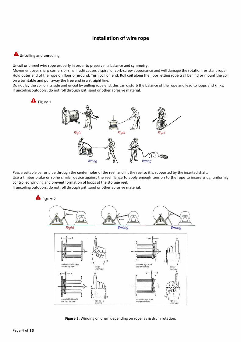
Installation of wire rope
Uncoiling and unreeling
Uncoil or unreel wire rope properly in order to preserve its balance and symmetry.
Movement over sharp corners or small radii causes a spiral or cork-screw appearance and will damage the rotation resistant rope.
Hold outer end of the rope on floor or ground. Turn coil on end. Roll coil along the floor letting rope trail behind or mount the coil
on a turntable and pull away the free end in a straight line.
Do not lay the coil on its side and uncoil by pulling rope end, this can disturb the balance of the rope and lead to loops and kinks.
If uncoiling outdoors, do not roll through grit, sand or other abrasive material.
Figure 1
Pass a suitable bar or pipe through the center holes of the reel, and lift the reel so it is supported by the inserted shaft.
Use a timber brake or some similar device against the reel flange to apply enough tension to the rope to insure snug, uniformly
controlled winding and prevent formation of loops at the storage reel.
If uncoiling outdoors, do not roll through grit, sand or other abrasive material.
Figure 2
Figure 3: Winding on drum depending on rope lay & drum rotation.

Page 5 of 13
Proper winding of wire rope on the winch
Equally vital and of great importance is the winding of the new wire rope under tension on the ship's storage & tension winch
drum. The proper tensioning load should be approx. 2% of the minimum breaking load of the rope. If a tensioning device is not
present or is impossible to apply the tensioning load using a special device, please use a wooden board in order to "brake" the
pay-off reel. Do not use pressure on the rope itself in order to generate the required tension as structural damage and
permanent deformation on the rope might occur. Another solution is to wind the whole length of the rope on the winch, then
unwind it until the first layer appears and then apply a tension equal to the 2% of the rope's minimum breaking load so that the
required tension level is achieved and then continue to wind the rope on the winch storage drum.
Ideally, 5-6 turns must be on the tension drum of the winch for avoiding slippage and high stresses.
According to our experience and based on studies effected and verified in the past, the tension amplification profile is governed by
the Euler – Eytelwein capstan equation.
TLOAD = THOLD eµϕ
Considering a friction co-efficient of 0,1, the table shows the approx. tension applied to the first turn of the wire rope depending
on the number of turns on the tension drum.
Turn number (THOLD is imposed) 1 2 3 4 5 6
Tension on First turn as a % of the Mooring
Tension applied on the rope during
mooring (TLOAD)
53.35% 28.46% 15.18% 8.10% 4.32% 2.31%
As shown above, 5 - 6 turns impose the lowest stresses on the rope in the tension drum assisting in the longevity of the rope and
safety of the operations.
Tension drum diameter must be at least 16 times the rope diameter for reducing fatigue effects on the rope.
Break in Period
After installing a new rope, it is necessary to run it through its operating cycle several times under light load and at reduced speed.
This allows the rope to adjust itself to the working conditions and enable all strands and wires to become seated. Depending on
rope type and construction, some rope stretch and a slight reduction in rope diameter will occur as the strands and core are
compacted. This way the rope is less liable to be damaged when full load is applied.
The initial stretch (constructional stretch) is a permanent elongation that takes place due to slight lengthening of the rope lay and
due to a slight decrease in rope diameter. Constructional stretch generally takes place during the first 10-20 operations, and
increases the rope length by between 1/2% for fiber core rope, approx. 1/4% for 6-strand steel core rope, and approaches zero for
compacted ropes

Page 6 of 13
Twisting of strands (kinking)
Some rotation may occur in the initial operations. This rotation may result from the cabling of the parts of rope or from the
following causes:
Torque induced during installation of rope
Torque induced by the operations
Torque induced by the drum
Removal of kinks: Under no load, turn the rope to the opposite direction until the rope aligns. If any non-linearity is apparent, rope
has deformed and must be discarded.
Storage
Wire ropes should be stored under a roof or a weatherproof covering so that moisture cannot reach them. Similarly, acid fumes or
any other corrosive atmosphere must be avoided in order to protect the rope from rust. If a reel is to be stored for a long period, it
can be covered with a protective cloth. If not covered, the outer layers of rope should be generously coated with rope lubricant.
In case a rope is taken out of service and stored for future use, it should be placed on a reel after it has been thoroughly cleaned
and re-lubricated. Used ropes should be given the same storage considerations as new ropes. Every 6 months inspect the ropes for
lubrication drying out and re-apply as needed.
Wire rope in storage should be kept away from steam or hot water pipes, heated air ducts, or any other source of heat which can
thin out lubricant and cause it to drain out of rope.
Improper storage & incomplete maintenance, that will result in a shortened service lifetime, includes, among others, the following:
-Salty/humid environment
-Corrosive/Acid/Dusty environment (chemical fumes, gritty / sandy environment and the like)
-High or low temperatures that will affect the lubricant inside the rope (so every 3 months ropes must be turned upside down)
-Lubrication (type of lubricant): Very important that a proper lubricant is used (specialized for wire ropes, with high drop point).
-Waviness of the rope (that must be straightened before rope is put in operation, eg, with a 10% of the MBL / LDBF of the wire
rope applied overnight)
-Improper handling
-Inadequate ventilation
-Lack of intermediate inspection of the stored ropes every 3 months
Before taken into use, the rope must be visually inspected along its full length for broken wires, waviness, lack of lubricant (if high
temperatures were prevailing during storage), corrosion signs (pitting, oxidation). For additional safety, you can have a piece of the
rope tested to destruction (breaking load test), however this will reduce the original rope length by the specimen's length and
leave one end of the rope without pressed eye splice.
Unreeling & uncoiling must be effected correctly as per provided instructions.
Important remarks:
--Always follow the rule: First in - First out for the spare ropes in your possession, meaning that ropes must be used in the order of
delivery on board. By this, you make sure that older delivered ropes are being put into service first and not after being stored for
many years. This is accomplished by marking the reel / coil with a suitable date / number etc and by following the delivery logs /
records.
--Apply a coat of lubricant on the top layer of the rope in the reel every 3 months
--Removed ropes awaiting further use, should be thoroughly cleaned, inspected, lubricated and stored under the same conditions
as new ropes.
--Re-lubrication (during usage), must be effected by means of a pressure lubricator
After 2 years (of proper) storage & maintenance, it is advisable to rewind the stored ropes to another reel, with core diameter
bigger than the current (eg from 15x to 20x). This should be repeated every 1-2 years afterwards. Maintenance must continue as
advised above for as long the rope remains under storage. No significant / measurable loss is effected per year of storage (less
than 1% per year).

Page 7 of 13
Expiry date of the steel wire ropes under storage: Inspection will determine, according to the discard criteria & OCIMF's MEG4
discard limit at 25% strength loss of sdMBL, if rope can be put in service after a period of storage.
Wire rope inspection
Note : Please read the “Operator Handbook for steel wire mooring ropes HYPERMAX 6S about Inspection
& discard as per OCIMF MEG 4 Guidelines”
Deformations/ Defects
A wire broken under a tensile load that exceeds its strength is recognized by the "cup and cone" configuration at the fracture point
(a). The necking down of the wire at this point shows that failure occurred while the wire retained it ductility. Shear-tensile
fracture (b) occurs in wire subjected to a combination of transverse and axial loads. Fatigue breaks are usually characterized by
squared-off ends perpendicular to the wire either straight across or Z-shaped (c&d).
Figure 1
If special rope damage is found, the cause has to be determined and eliminated before a new rope is installed.
If in doubt, discard rope or consult our company for further assistance.
Specific inspection procedures and frequency should be defined and documented as part of the operator’s LMP.
Only qualified and experienced personnel, taking the appropriate safety precautions and wearing the appropriate protective
clothing, should be responsible for inspecting wire in service.
The main causes of deterioration of wire are excessive wear, broken wires or strands, distortion and corrosion. Areas that should
be regularly inspected as part of the LMP include:
Winch anchor point and the section of wire close to it.
Sections of rope in wear zones, particularly sections that run regularly through deck fairleads and around
pedestal rollers.
The eye, especially at the bend of the eye and its termination.
Cross-overs on winch drum.
Terminations, particularly the Talurit type, to identify any looseness, cracks, distortion or corrosion.
Rope inspection summary
Any wire rope that has broken wires, deformed strands, variations in diameter or any change from its normal appearance must be
considered for replacement. It is always better to replace a rope when there is any doubt concerning its condition or its ability to
perform the required task. The cost of wire rope replacement is quite insignificant when considered in terms of human injuries,
the cost of down time, or the cost of replacing broken structures.
Wire rope inspection includes examination of basic items such as:
Rope diameter reduction | Rope lay | External wear |Internal wear | Peening | Scrubbing | Corrosion | Broken wires
Some wire rope sections can break up without any visible warning.

Page 8 of 13
Sections where this occurs are usually found at end terminations,. Because of the "working" that takes place at those sections,
neither appreciable external wear nor crown breaks will appear. Under such conditions the core fails thereby allowing adjacent
strand nicking. When this happens, valley breaks are likely to appear and the rope should be removed.
If preventive maintenance is performed diligently, rope life can be prolonged.
Cutting off an appropriate length of rope at the end termination before the core degrades, and valley breaks appear, minimizes
degradation.
Use and care of wire rope
What follows is a brief outline of the basic information required to safely use wire rope
Wire rope will fail if WORN OUT, OVERLOADED, MISUSED, DAMAGED, OR IMPROPERLY MAINTAINED.
In service, wire rope loses strength and work capability. Abuse and misuse increase the rate of loss.
The Line Design Breaking Force or MINIMUM BREAKING STRENGTH of wire rope applies ONLY to a NEW, UNUSED rope.
The Minimum Breaking Strength should be considered the straight line pull with both rope ends fixed to prevent rotation,
which will ACTUALLY BREAK a new, UNUSED, rope. The Minimum Breaking Strength of a rope should NEVER BE USED AS
ITS WORKING LOAD.
To determine the working load of a wire rope, the MINIMUM or NOMINAL Breaking Strength MUST BE REDUCED by a
DESIGN FACTOR (formerly called Safety Factor). The Design Factor according to the MEG 4 Guidelines is 1,82, which is the
55% of the Minimum Ship Design Breaking Load.
WIRE ROPE WEAR OUT. The strength of a wire rope slightly increases after the break in period, but will decrease over
time. When approaching the finite fatigue life span the breaking strength will sharply decrease. Never evaluate the
remaining fatigue life of a wire rope by testing a portion of a rope to destruction only. An in-depth rope inspection must
be part of such evaluations.
NEVER overload wire rope. This means NEVER use the rope where the load applied is greater than the working load.
NEVER 'SHOCK LOAD' a wire rope. A sudden application of force or load can cause both visible external damage (e.g. bird
caging) and internal damage. There is no practical way to estimate the force applied by shock loading a rope. The sudden
release of a load can also damage a wire rope.
Lubricant is applied to the wires and strands of a wire rope when manufactured. This lubricant is depleted when the rope
is in service and should be replaced periodically.
Regular, periodic INSPECTIONS of the wire rope, and keeping of PERMANENT RECORDS SIGNED BY A OUALIFIED
PERSON, are required by OCIMF, OSHA and other regulatory bodies for almost every rope installation. The purpose of
inspection is to determine whether or not a wire rope may continue to be safely used on that application. Inspection
criteria, including number and location of broken wires, wear and elongation, have been established by DIN, ISO, CEN,
OSHA, ANSI, ASME and other organizations.
If in doubt, replace the rope.
When a wire rope has been removed from service because it is no longer suitable, IT MUST NOT BE RE-USED IN ANOTHER
APPLICATION.
Every wire rope user should be aware of the fact that each type of fitting attached to a wire rope has a specific efficiency
rating which can reduce the working load of a rope system (like the mooring system), and this must be given due
consideration in determining the capacity of a wire rope system.
Some conditions that can lead to problems in a wire rope system include:
Broken wires mean a loss of strength. Kinks permanently damage a wire rope.
Environmental factors such as corrosive conditions and heat can damage a wire rope.
Lack of lubrication can significantly shorten the useful service life of a wire rope.
Contact with electrical wire and the resulting arcing will damage a wire rope.
Areas that should be given operator’s attention include the following:
Winch anchor point and the section of wire close to it
Sections of rope in wear zones, particularly sections that run regularly through deck fairleads and around
pedestal rollers
The eye splice, especially at the bend (bow) of the eye and its termination
Cross-overs on winch drum
Terminations, particularly the aluminium Talurit ferrule, to identify any looseness, cracks, distortion or
corrosion

Page 9 of 13
Discard criteria for wire ropes - when to replace wire rope based on various deformations (number of
broken wires, diameter reduction etc) as per ISO 4309 standard & OCIMF’s MEG 4 Guidelines
Inspection Criteria Discard Criteria
Visible wire breaks Number in length of 6d or 30d Discard if over 4 in length 6d or 8 over
30d (RHOL & LHOL ropes)
Wire breaks at termination Evidence of broken wires Remake termination or discard rope
Fracture of strand Strand fracture Discard if present
Reduction of rope diameter Percentage reduction Discard if diameter decreased by 10%
Abrasion of outer wires Degree of deterioration (%) Discard if over 7%
Rope lay length: Approx equiv to 6 x d (d is the nominal rope diameter)
Fracture of strands: If a complete strand fracture occurs, the rope must be immediately discarded (ISO 4309 §6.4).
Mooring Wires Connection
a) Connection with Mooring Link
b) Connection with Mooring Shackle
Bear in mind that Cow Hitch or any other knot based solution to connect a mooring wire with synthetic tails is not safe
and is not recommended.

Page 10 of 13
The maintenance of steel wire ropes
Wire rope cleaning and lubrication best practice
The information in this guide has been gained from working with wire rope, OEMs and extensive field
experience with customers using mooring wire ropes.
a) Cleaning
Prior to lubrication, effective cleaning of wire ropes can enhance the performance, corrosion resistance and ultimately
the life of wire ropes. Both dynamic and standing ropes will naturally attract dirt over time. By removing old lubricant
and cleaning back to the bare metal, lubricant will naturally penetrate deeper into the rope. Lubricating over a dirty
wire rope can force dirt into the rope and act as an abrasive. Adhesion of the lubricant to the rope will also improve as
the new lubricant will have more of an affinity to the rope than to a layer of old grease. When new grease is applied
over an old heavily lubricated rope, it may reduce its adhesive performance. It is important to understand that if
a new wire rope is fitted, it may come with a heavy build lubricant applied from the manufacturer. When stored in hot
climates over time, wax based build lubricants can harden with a glass-like finish. This will prevent any service
lubricant being able to penetrate or adhere to the rope effectively. This should be noted when fitted and monitored in
service. Initial inspection periods should determine the re-lubrication at a suitable time when the build lubricant has
loosened. The use of solvents for cleaning wire ropes should be avoided and can be harmful to operators and
aquatic environments. Jet washing and steam cleaning should also be avoided as the forceful ingress of water can
be difficult to displace and increase the likelihood of internal corrosion. Effective cleaning of wire ropes is a
difficult task. However, there are various ways to make this easier. The rope and its accessibility will determine the
best way to carry this out. Ropes that are difficult to access may be cleaned the mechanically with a stiff nylon brush.
High pressure lubricant applicators often have cleaning rings or scrapers that clean the rope prior to applying lubricant.
These tend to be the quickest and easiest method of cleaning and lubricating in one pass. If corrosion is present it
should not be mechanically abraded to remove it, for example with a wire brush. Although this would remove the
surface corrosion, it may also remove any remaining galvanic protective layer. The bare metal is then more
susceptible to flash corrosion.
b) Fluid or Grease?
A solvented fluid wire rope lubricant has a natural tendency to displace water. For that reason it is excellent for the
lubrication of wet wire ropes. For marine applications such as tug boat wires, this can be beneficial to chase off water
internal to the core of the wire rope. Fluids can easily be applied using a spray type system, often incorporating
compressed air. For smaller applications such as hoists wires, backpack sprayers (that are resistant to oils and solvents)
can be used to easily apply the lubricant. A benefit of a fluid is that it will exhibit greater penetration into the wire rope
than a standard grease. Penetration is essential for a lubricant to coat the internal strands to prevent wear and internal
corrosion. A drawback of a fluid is that the lubricant life span is lower so application frequency is greater compared to
a grease.
c) Environmentally Considerate Lubricants
For wire ropes in marine environments, it is important that an environmentally considerate product is selected.
These are developed to be high performance, biodegradable, non -toxic to marine environments and non-bio
accumulative. The use of products containing mineral oils should be avoided as these can be very harmful to the
environment, marine life and operators applying them. Failure to comply can result in heavy fines being issued the
Environmental Protection Agency (EPA).

Page 11 of 13
d) Compatibility
The recommended wire rope lubricant products for the mooring wire rope HYPERMAX 6S are the ROCOL. They are
fully compatible with other brand wire rope lubricants. However, applying ROCOL wire rope lubricants over
excessive amounts of previously used or build lubricant may restrict the performance. The product Wireshield of
ROCOL is the unique grease with pseudoplastic rheology. This unique technology aids penetration of the lubricant into
strands of wire rope, ensuring deeper protection for long time.
Figure 1.1 — Pseudoplastic rheology -Wireshield
e) Lubricant Application
An application method should be selected that is suitable for the wire rope and the asset it is fitted to. ROCOL
recommends the use of a wire rope pressure applicator when possible. These have the benefits of effectively
cleaning the wire rope with a helical grooved cleaning ring, prior to the lubricant application. They also apply the
grease with pressure, promoting penetration and leaving a thin and even lubricating film. If not using a pressure
applicator, wire ropes can be cleaned using a stiff bristled brush if required. Solvents and cleaning fluids should
not be used for cleaning. ROCOL wire rope products can also be applied by hand. This can be either swaging or
brushing and care should be taken to get good coverage of the rope. When applied by hand, wire rope lubricants
should be worked into the surface of the wire rope to aid coverage and penetration. Over application should be
avoided to prevent excessive usage, build-up of grease on sheaves and prevent fling.
f) Lubricant consumption
Lubricant consumption can be vary widely depending on many factors such as age of the rope, size and construction,
lubricant choice, application method, temperature of application, environmental factors (wet/hot/cold weather
or sunlight UV exposure),load cycles, rope speeds, water depth/pressure etc. There are various calculators
(available on request) that will give a guide to the amount of lubricant required for the size/length of asset you
have. As a good starting point a grease will give approximate rope coverage, based on a 25mm diameter rope, of 50
meters per kg.

Page 12 of 13
g) Re-lubrication Periods
Re-lubrication periods can vary widely according to the same factors mentioned in the above lubrication consumption.
Depending on the operation or location of the asset it will dictate when it is possible to lubricate. A general rule
of thumb would be every 6 months. If the rope is in constant operation or extreme environments, this can be
significantly shortened. Conversely, it could be lengthened if the rope is subject to less harsh environments.
Removing broken wires
If, during an inspection, ends of broken wires are detected, which might cross adjacent wires and destroy them when running over
sheaves, these broken wire ends must be removed.
Under no circumstances should the broken wire ends be pinched off with a pair of nippers (see figure below). The best method is
to move the wire ends backwards and forwards until they break deep in the valley between two outer strands (see figure below).
With thicker wires a tool should be moved backwards and forwards on the surface of the rope, thus bending the wires until they
break.
Diagnostic guide to common wire rope degradation
Mode Symptoms Possible causes
Fatigue
Wire break is transverse-either
Straight across or Z shape. Broken
Ends will appear grainy.
Check for rope bent around too small a radius; vibration or whipping; wobbly sheaves;
rollers too small; reverse bends; bent shafts; tight grooves; corrosion; small drums &
sheaves; incorrect rope construction; improper installation; poor end terminations. (In
the absence of other modes of degradation, all rope will eventually fail in fatigue.)
Tension Wire break reveals a mixture of cup
and cone fracture and shear breaks.
Check for overloads; sticky, grabby clutches; jerky conditions; loose bearing on drum;
fast starts, fast stops, broken sheave flange; wrong rope size & grade; poor end
terminations. Check for too great a strain on rope after factors of degradation have
weakened it.
Abrasion
Wire break mainly displays outer
wires worn smooth to knife edge
thinness. Wire broken by abrasion in
combination with another factor will
show a combination break.
Check for change in rope or sheave size; change in load; overburden change; frozen or
stuck sheaves; soft rollers, sheaves or drums; excessive fleet angle; misalignment of
sheaves; kinks; improperly attached fittings; grit & sand; objects imbedded in rope;
improper grooving.
Abrasion Plus
Fatigue
Reduced cross-section is broken
off square thereby producing a
chisel shape.
A long-term condition normal to the operating process.
Abrasion Plus
Tension
Reduced cross-section is necked
down as in a cup and cone
configuration. Tensile break
produces a chisel shape.
A long-term condition normal to the operating process.
Cut or Gouged
Or Rough Wire
Wire ends are pinched down,
mashed and/or cut in a rough
diagonal shear-like manner.
Check on all above conditions for mechanical abuse, or either abnormal or accidental
forces during installation.
Torsion or
Twisting
Wire ends show evidence of twist
and/or cork-screw effect.
Check on all above conditions for mechanical abuse, or either abnormal or accidental
forces during installation.
Mashing Wires are flattened and spread at
broken ends.
Check on all above conditions for mechanical abuse, or either abnormal or accidental
forces during installation. (This is a common occurrence on the drum.)

Page 13 of 13
KATRADIS VEP SA
DISCLAIMER
Katradis VEP SA, to the best of its knowledge, uses reasonable efforts to include accurate and up-to date information on this manual; it does not,
however, make any warranties or representations, either express or implied, as to its accuracy or completeness. All material and information
provided on this manual are provided “as is” without warranty of any kind, either express or implied, including warranties of merchantability,
fitness for a particular purpose, commercial viability, title or non – infringement.
Katradis VEP SA. and its affiliates assume no liability or responsibility for any errors or omissions in the content of this manual. It is the
responsibility of the user to ensure the proper use, handling, maintenance and routine inspection of Steel Wire Ropes. Under no circumstances
and under no legal theory shall Katradis VEP SA, its affiliates, its suppliers, or any other party involved in creating, producing, or delivering this
manual’s contents be liable to the users for any indirect, direct, special, incidental, or consequential damages arising from any cause whatsoever.