“CrystalBall” - SOFTOOL Microelectronics SA
10
“CrystalBall” “CrystalBall” ARM9 CPU based module ARM9 CPU based module CrystalBall – ARM9 CPU module - Overview SOFTOOL Microelectronics - Preliminary - 1
-
Upload
khangminh22 -
Category
Documents
-
view
5 -
download
0
Transcript of “CrystalBall” - SOFTOOL Microelectronics SA

“CrystalBall”“CrystalBall”
ARM9 CPU based moduleARM9 CPU based module
CrystalBall – ARM9 CPU module - Overview SOFTOOL Microelectronics - Preliminary - 1

ContentsChapter 1 Overview.......................................................................................................................................................... 3Chapter 2 Functional Description................................................................................................................................... 4
2.1 Block diagram:....................................................................................................................................... 42.2 Microprocessor i.MX1............................................................................................................................ 4
2.2.1 ARM920T....................................................................................................................................... 42.2.2 LCD Controller............................................................................................................................... 52.2.3 Video port ...................................................................................................................................... 52.2.4 USB device port............................................................................................................................. 5
2.3 FPGA..................................................................................................................................................... 52.4 FLASH Memory..................................................................................................................................... 62.5 Ethernet................................................................................................................................................. 62.6 Real-Time Clock ................................................................................................................................... 62.7 CEI - Interface........................................................................................................................................ 62.8 JTAG...................................................................................................................................................... 72.9 Performances scaling............................................................................................................................ 8
Chapter 3 Electrical specifications................................................................................................................................. 9
3.1 Absolute Maximum ratings..................................................................................................................... 9Chapter 4 Mechanical Specifications........................................................................................................................... 10
CrystalBall – ARM9 CPU module - Overview SOFTOOL Microelectronics - Preliminary - 2

Chapter 1 Overview
The SOFTOOL Microelectronics's CrystalBall module is an extremely versatile microcomputer board built around the Freescale i.MX1 CPU. The i.MX1 features an array of on-chip peripherals including LCD, Image capture, UART, SPI, I²C, USB, Bluetooth, MMC/SD controllers, all of them available to the user application. To boost power and simplify the interfacing with the customer application hardware, the CrystalBall module integrates a powerful, on-fly configurable FPGA. The on-board FPGA is the CrystalBall's key point, which makes the difference between CrystalBall and most of similar concurrent products.The on-board FPGA Altera Cyclone EP1C6 can be programmed to accomplish tasks starting from simple glue logic till more complex co-processing functions. It basically acts as a bridge to the outside world, filling the gap between standard i.MX1 peripherals and the more specific custom application requirements.Although conceived as an image processor (acquisition-processing-visualisation) thanks to its particularly architecture (i.MX1 – FPGA coupling) the CrystalBall module offer an incredible power and flexibility.Four 60 pin connectors (total of 240 connection points) here after called CEI (Configurable Expansion Interface) bring all the i.MX1 peripherals and most of the FPGA I/O to the outside world, offering an amazing degree of interconnection with the customer HW.10/100MBit network support is done by the SMC-91C111 Ethernet controller which integrates the PHY layer, so ready to drive the transformers.The CrystalBall has the following main features:
• Freescale MC9328MX1-200MHz CPU• 64 MB (16Mx32) SDRAM• 16 MB (8Mx16) NOR Flash • 128 KB Static RAM (i.MX1 internal)• FPGA Altera Cyclone EP1C6, 5'980 Logical Elements)• SMC91C111 10/100Mbit Ethernet (Optional)• LCD Controller up to VGA resolution 640 x 480• CMOS Image sensor interface (Video port)• Three Universal Asynchronous Receiver/Transmitters (UART 1, 2 and 3)• Serial Peripheral Interface (SPI)• Two Synchronous Serial Interfaces and Inter-IC Sound (SSI/I2S) Module• I²C Bus Module• 1-wire Bus controller• USB Device with integrated physical layer• Bluetooth Accelerator (BTA)• MMC/SD cards and Memory Stick® Host Controller • SmartCard Interface Module (SIM)• Real-Time Clock (RTC) 1-wire DS4215• Pulse-Width Modulation for sound generation• Direct Memory Access Controller (DMAC)• JTAG for devices programming and software debug• C onfigurable Expansion Interface (240 pin) • Modules are stackable for performances scaling • Single 3.15V power supply• 80mm x 100mm (3.15” x 3.8”) size
CrystalBall – ARM9 CPU module - Overview SOFTOOL Microelectronics - Preliminary - 3

Chapter 2 Functional Description
2.1 Block diagram:
2.2 Microprocessor i.MX1The i.MX1 belongs to the Freescale's DragonBall application processors family. It features an advanced and power-efficient ARM920T core that operates at speeds up to 200 MHz. The i.MX1 specifically addresses the requirements of personal and portable products by providing intelligent integrated peripherals, an advanced processor core, and power management capabilities.For detailed technical and programming information about the i.MX1 processor refer to the “MC9328MX1 i.MX Integrated Portable System Processor Reference Manual “ or Freescale web site.
Integrated modules such as an LCD controller, static RAM, USB support, an A/D converter (with touch panel control), and an MMC/SD host controller offer a suite of peripherals to enhance any product seeking to provide a rich multimedia experience. Except for those listed below, all of the integrated peripherals are directly available on CrystalBall's CEI.
Peripheral not directly available on CEI:• CSI (see 2.2.3 Video Port)• SPI 1 (see 2.2.4 SPI 1 port)• PWM, routed to FPGA• Timer 2, routed to FPGA
2.2.1 ARM920TThe ARM920T processor is a high-performance 32-bit RISC integer processor macrocell featuring:
• ARM9 v4 core• 16 KB instruction and 16 KB data caches
CrystalBall – ARM9 CPU module - Overview SOFTOOL Microelectronics - Preliminary - 4
FLASH8Mx16
SDRAM16Mx32
CPUi.MX1FPGA
Eth 10/100
CEI (GPIO,LCD,CSI,UART,SPI,USB,SD/MMC ....)
CrystalBall module
RTC
Per
iphe
rals
Bus
System Bus1-
wire
Bus

• Instruction and data Memory Management Units (MMUs)• Write buffer• AMBA. (Advanced Microprocessor Bus Architecture) bus interface
For detailed technical and programming information about the ARM920T processor refer to the “ARM920TTechnical Reference Manual”
2.2.2 LCD ControllerThe i.MX1 LCDC features:
• Software programmable screen size (a maximum of 640 × 512 pixels)• Support single (non-split) monochrome, color STN panels, and color TFT panels• Support for 4 bpp (bits per pixel), 8 bpp and 12 bpp for passive color panels• Support for 4 bpp, 8 bpp, 12 bpp and 16 bpp for TFT panels• Up to 256 colors out of a palette of 4096 for 8 bpp• True 64K colors for 16 bpp• In color STN mode, the maximum bit depth is 12 bpp• In BW mode, the maximum bit depth is 4 bpp• Up to 16 grey levels out of 16 palettes• Capability to share system memory or internal SRAM for display memory• Capable of directly driving most of the popular LCD drivers
2.2.3 Video port To increase the flexibility the i.MX1 video port signals (CSI) are internally connected to the FPGA. To get the video port signals on CEI the FPGA must be configured to route the video signals to the desired FPGA I/O pins. In this way, when needed, the video stream may be pre-processed or in situations where the image sensor is located faraway from CrystalBall module the FPGA's LVDS signals can be used.
2.2.4 USB device portThe i.MX1 USB device port complies with the 'USB Release 1.1' specification. The CrystalBall module also integrates the USB physical layer, so ready to be wired to the USB's connector.
2.3 FPGAThe FPGA used on CrystalBall module is an Altera's Cyclone EP1C6 with the following main features:
• 5'980 LEs (Logical Elements)• 92'160 RAM bits (11'520 bytes)• Support for LVTTL, LVCMOS, SSTL-2, and SSTL-3 I/O standards• High-speed (640 Mbps) LVDS I/O support• Low-speed (311 Mbps) LVDS I/O support• 311-Mbps RSDS I/O support• Two PLLs per device provide clock multiplication and phase shifting
For detailed technical information about the Cyclone EP1C6 refer to the “Cyclone Device Handbook, Volume 1” or Altera web site.
The FPGA plays a key role on CrystalBall's flexibility. Up to 80 FPGA I/Os are available on CEI. The 16bit data-wide, 7bit addressable peripherals bus available on CEI is also derived from the FPGA. Upon needs the addressing range of the peripherals bus may be extended to 16bit.Internally the FPGA is directly connected to the lower 16bit data bus of the i.MX1 with an addressing range of up to 32MB (A0-A24), allowing full speed access to the internal customer created peripherals.In its basic configuration the FPGA is configured to implement the peripherals bus (used by Ethernet controller) and the 1-wire bus master controller. This configuration sinks about 7% of the total FPGA resources leaving a huge margin of flexibility.
CrystalBall – ARM9 CPU module - Overview SOFTOOL Microelectronics - Preliminary - 5
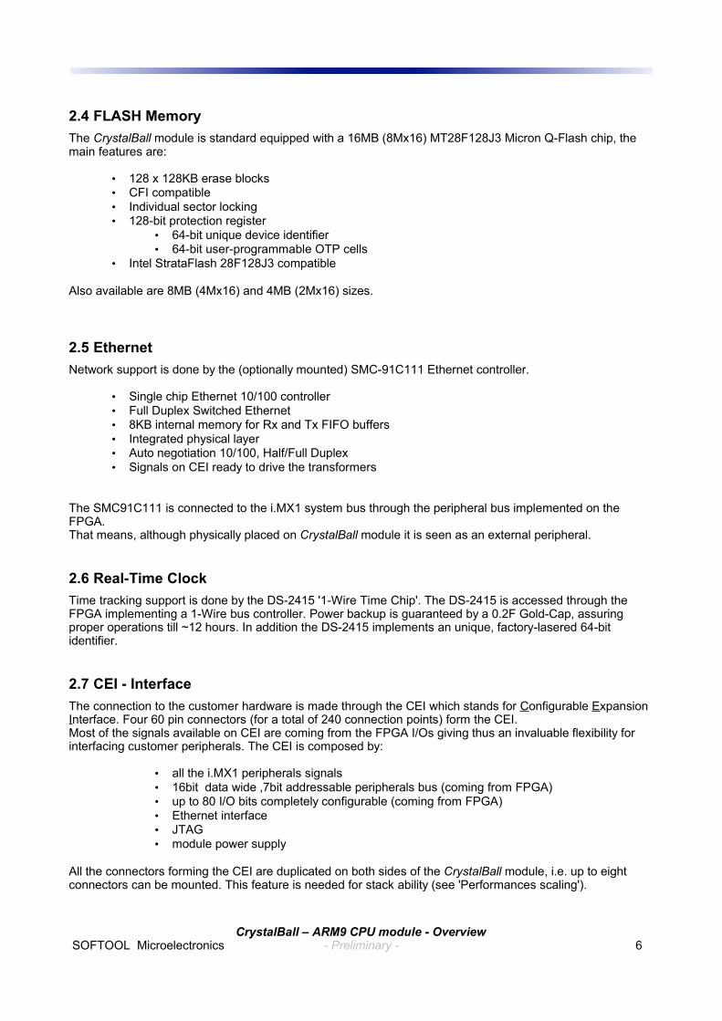
2.4 FLASH MemoryThe CrystalBall module is standard equipped with a 16MB (8Mx16) MT28F128J3 Micron Q-Flash chip, the main features are:
• 128 x 128KB erase blocks• CFI compatible• Individual sector locking• 128-bit protection register
• 64-bit unique device identifier• 64-bit user-programmable OTP cells
• Intel StrataFlash 28F128J3 compatible
Also available are 8MB (4Mx16) and 4MB (2Mx16) sizes.
2.5 EthernetNetwork support is done by the (optionally mounted) SMC-91C111 Ethernet controller.
• Single chip Ethernet 10/100 controller• Full Duplex Switched Ethernet• 8KB internal memory for Rx and Tx FIFO buffers• Integrated physical layer• Auto negotiation 10/100, Half/Full Duplex• Signals on CEI ready to drive the transformers
The SMC91C111 is connected to the i.MX1 system bus through the peripheral bus implemented on the FPGA.That means, although physically placed on CrystalBall module it is seen as an external peripheral.
2.6 Real-Time Clock Time tracking support is done by the DS-2415 '1-Wire Time Chip'. The DS-2415 is accessed through the FPGA implementing a 1-Wire bus controller. Power backup is guaranteed by a 0.2F Gold-Cap, assuring proper operations till ~12 hours. In addition the DS-2415 implements an unique, factory-lasered 64-bit identifier.
2.7 CEI - InterfaceThe connection to the customer hardware is made through the CEI which stands for Configurable Expansion Interface. Four 60 pin connectors (for a total of 240 connection points) form the CEI.Most of the signals available on CEI are coming from the FPGA I/Os giving thus an invaluable flexibility for interfacing customer peripherals. The CEI is composed by:
• all the i.MX1 peripherals signals• 16bit data wide ,7bit addressable peripherals bus (coming from FPGA)• up to 80 I/O bits completely configurable (coming from FPGA)• Ethernet interface• JTAG• module power supply
All the connectors forming the CEI are duplicated on both sides of the CrystalBall module, i.e. up to eight connectors can be mounted. This feature is needed for stack ability (see 'Performances scaling').
CrystalBall – ARM9 CPU module - Overview SOFTOOL Microelectronics - Preliminary - 6
2.8 JTAGJTAG chain allows in-circuit devices programming or software debugging by using external debugger devices like the BDI2000.The i.MX1 and the FPGA are daisy chained in the following device order:
1. i.MX1 (IR length 4)2. Altera FPGA (IR length 10)
When modules are stacked (see 'Performance Scaling') every module is daisy chained as well, i.e.:1. i.MX1 module 12. FPGA module 13. i.MX1 module 24. FPGA module 2
The JTAG interface is available on CEI.
CrystalBall – ARM9 CPU module - Overview SOFTOOL Microelectronics - Preliminary - 7

2.9 Performances scalingOne of the strongest points of CrystalBall module is its ability to scale performances by simply duplicate itself. Where applications require high processing power e.g. driving full color hi-res Lcd pannel with acquisition&display of full color live images, CrystalBall modules may be stacked to obtain the required performances :
Module 2
Module 1
In the above example module 1 (base module) carries on all the high level tasks (e.g. Linux OS, application, network ...) whereas module 2 acts as a graphic co-processor driving a full color hi-res LCD panel able to capture and display live images. The two modules communicate through FIFOs or Dual Ported RAM implemented in the FPGA and connected by CEI.
In this configuration only one module (e.g. Module 1) can drive a selected i.MX1 peripheral or FPGA I/O, the other one must drive the corresponding pins in three-state. This is quite obvious since the CEIs of all the modules are connected together.
CrystalBall – ARM9 CPU module - Overview SOFTOOL Microelectronics - Preliminary - 8

Chapter 3 Electrical specifications
3.1 Absolute Maximum ratings
VCC Power Supply -0.3V to 3.3VVCC1 Power Supply -0.5V to 4.6VBTVDD Power Supply -0.3V to 3.3VVP Power Supply 2.6V to 4VVBAT Power Supply -0.5V to 3.3V
Operating Temperature Range 0°C to 70°CStorage Temperature Range -40°C to 85°CRelative Humidity Range 10% to 90% (no-condensing)
WARNINGStressing the module beyond the Absolute Maximum Ratings may cause permanent damage. These are stress ratings only. Operation beyond the Maximum Ratings is not recommended and extended exposure beyond the Maximum Ratings may affect reliability.
CrystalBall – ARM9 CPU module - Overview SOFTOOL Microelectronics - Preliminary - 9

Chapter 4 Mechanical Specifications
CrystalBall – ARM9 CPU module - Overview SOFTOOL Microelectronics - Preliminary - 10
80mm
100m
m
73mm
93m
m43
mm
68mm
FLASH
i.MX1
FPGAEP1C6
SMC91C111
SD
RA
M
SD
RA
M
RTC
3.2mm