
Journal article - 2014 IJIC
11
1 23 International Journal of Industrial Chemistry ISSN 2228-5970 Volume 5 Number 2 Int J Ind Chem (2014) 5:1-9 DOI 10.1007/s40090-014-0015-7 Application of acidic accelerator for production of pure hydrogen from NaBH 4 Wameath S. Abdul-Majeed, Muhammad T. Arslan & William B. Zimmerman
-
Upload
independent -
Category
Documents
-
view
0 -
download
0
Transcript of Journal article - 2014 IJIC
1 23
International Journal of IndustrialChemistry ISSN 2228-5970Volume 5Number 2 Int J Ind Chem (2014) 5:1-9DOI 10.1007/s40090-014-0015-7
Application of acidic accelerator forproduction of pure hydrogen from NaBH4
Wameath S. Abdul-Majeed, MuhammadT. Arslan & William B. Zimmerman
1 23
Your article is published under the Creative
Commons Attribution license which allows
users to read, copy, distribute and make
derivative works, as long as the author of
the original work is cited. You may self-
archive this article on your own website, an
institutional repository or funder’s repository
and make it publicly available immediately.
RESEARCH
Application of acidic accelerator for production of pure hydrogenfrom NaBH4
Wameath S. Abdul-Majeed • Muhammad T. Arslan •
William B. Zimmerman
Received: 2 July 2013 / Accepted: 4 April 2014
� The Author(s) 2014. This article is published with open access at Springerlink.com
Abstract Feasibility of using hydrochloric acid (HCl) as
an accelerator for onboard production of hydrogen from
sodium borohydride (NaBH4) is investigated. The aim was
to examine process efficiency, hydrogen purity and process
controllability which concurs onboard 2015 hydrogen
storage target (5.5 wt%) for vehicular fuel cell system
application. Results showed that a highest yield and con-
trollable hydrogen production rate are achievable upon
adopting onboard reaction of HCl (3 M) and an aqueous
alkaline solution of 30 % NaBH4 via a T-junction and
applying a gas–liquid separation of two stages. Cost eval-
uation and product stream analysis have demonstrated an
exceptional performance for the examined scheme and
relevancy to be adopted for feeding vehicular electro-
chemical fuel cell systems.
Keywords Fuel cells � Solid state hydrogen storage �Sodium borohydride
Introduction
In view of the fact that hydrogen is the key energy carrier,
interests are increasingly exhibited to utilize it as a fuel for
internal combustion engines and electrochemical fuel cells.
Nevertheless, technical issues such as storage and trans-
portation are still big barriers against its wider use [1].
Hydrogen can be stored physically as a compressed gas
or in liquid form. Nonetheless, pressures required for
compression are too high because of its low boiling and
melting points. Thus, very few materials, so far, can
handle this much pressure. Hence, compressed hydrogen
is not user friendly due to the risk of leakage and
explosion hazards, which limits its commercial availabil-
ity worldwide [2]. On the other hand, fuels such as
methanol, ethanol and methane can be a source of
hydrogen. However, operational requirements (e.g. high
temperature) are restricting its economic use for fuel cell
applications [3]. Alternatively, hydrogen can be stored
chemically in a solid state medium such as metal and
chemical hydrides which are considered to have a great
potential to store hydrogen effectively and safely under
standard conditions [4]. Principally, chemical hydrides are
more advantageous compared with metal hydrides in
terms of hydrogen content, storage capacity and opera-
tional requirements [5]. As a safe onboard hydrogen
storage candidate, sodium borohydride (NaBH4)
has gained the highest gravimetric/volumetric hydrogen
storage capacity over other chemical hydrides (theoreti-
cally = 10.8 wt%) as well as other features such as non-
flammable, non-toxic chemical and its stability in dry and
alkaline conditions.
Although voluminous literatures showed a significance
of applying solid state hydrogen generation system for
vehicular portable applications, it has been given a No-Go
recommendation by the US Department of Energy (DOE)
due to several technical and economical issues. Reasons
were reported to be mainly related to a difficulty in recy-
cling meta-borates to borohydride and incapability to
achieve system storage targets [6].
Hydrogen can be generated from sodium borohydride
through catalytic hydrolysis reaction at low temperature, in
which four moles of hydrogen are released in addition to
the sodium meta-borate as by-products [7, 8].
W. S. Abdul-Majeed (&) � M. T. Arslan � W. B. Zimmerman
Department of Chemical and Biological Engineering,
The University of Sheffield, Sheffield S1 3JD, UK
e-mail: [email protected]
123
Int J Ind Chem (2014) 5:15
DOI 10.1007/s40090-014-0015-7
NaBH4 þ 2H2O �!Catalyst4H2 þ NaBO2ðaqÞ þ Heat ð1Þ
Using sodium borohydride at 10–15 wt% was consid-
ered to be optimal by several researchers [9], as it reacts
very slowly with water. Therefore, it can be stopped readily
by addition of alkaline medium (e.g. sodium hydroxide) or
accelerated by adding acids or applying catalysts (e.g.
metals of both noble and non-noble nature) [10]. Although
a catalyst (e.g. RU) was reported to be able, theoretically,
to provide up to 100,000 turnovers, nonetheless, practical
issues such as onboard regeneration were found to be a big
barrier against its industrial adaptation. Hence, higher
hydrogen yield and conversion efficiency are better
achieved when applying acid catalysts. This is due to the
fact that all reacting species (H?) are completely consumed
and therefore the hydrogen generation rate is controlled
precisely through addition of acid, which is highly
requested for onboard applications. The acidic scheme is
illustrated by the following reaction [9, 10].
NaBH4 þ 3H2Oþ HCl! 4H2 þ H3BO3 þ NaCl ð2Þ
Utilization of acid accelerators for NaBH4 hydrogen
generation system was first tested in 1950s, in which more
than 20 acids were assessed (e.g. oxalic acid, citric acid,
boric acid, formic acid and many others). The results
showed that the reaction upon adding these acids was very
violent and vigorous; hence it was decided to choose a
relatively safer option [7]. Until beginning of 2000, acids
were found unsuccessful accelerators for NaBH4 hydroly-
sis due to safety issues. However, recent research
endeavour showed that some acids can be used as potential
direct accelerators or indirect activator for heterogeneous
catalysts (Xu et al. 2008 and [11, 12]). Moreover, there
were few acids suggested by [13] which could be used as a
single-use accelerator for a portable NaBH4 hydrogen
generation system. These acids include hydrochloric acid,
sulphuric acid, nitric acid, phosphoric acid, formic acid and
acetic acid. They also found that some acids possess the
ability to delay formation of hydrated by-products, via
shifting pH to lower values, and thereby NaBH4 hydrolysis
could be improved [3].
Main advantages of the acidic hydrolysis scheme are:
(1) acid accelerators can be stored as an aqueous solution
of variable concentrations, (2) the scheme can be per-
formed at room temperature, (3) sodium meta-borate pro-
duced was shown to be barely toxic and environmental
friendly, which makes it possible to be recycled, (4) high
purity hydrogen gas can be obtained, which suits highly
sensitive fuel cells such as Proton Exchange Membrane
Fuel Cell, (5) upon using acid accelerator, formation and
crystallization of by-products is delayed or inhibited, and
(6) Practically, even with 1:1 (HCl:NaBH4 stoichiometric
ratios), applying acidic scheme is believed to be cost-
effective option for onboard fuel cell applications, taking
into consideration the operational troublesome for metal
catalysts (e.g. Ruthenium, CoCl2). Consequently, acid
accelerators may act effectively for onboard fuel cell
applications should a sophisticated scenario defines the
optimal operating conditions becomes applicable.
It is worth noting that an acidic hydrolysis scheme was
explored with less attention compared with catalytic
schemes, therefore it is required to conduct further
researches toward better system understanding and to
measure feasibility for a portable fuel cell application.
In a previous work [14], we investigated the perfor-
mance of liquid nitrogen cold trap for purifying a hydrogen
stream generated from catalytic and acidic decompositions
of NaBH4. In the current research, an increase of hydrogen
yield is attempted by applying a higher concentration of
acidic accelerator and NaBH4 concentration up to 30 wt%
in an aqueous alkaline solution. The paper is arranged in
four parts, in which an experimental description, results
and discussion and conclusions are presented in the fol-
lowing sections.
Methods
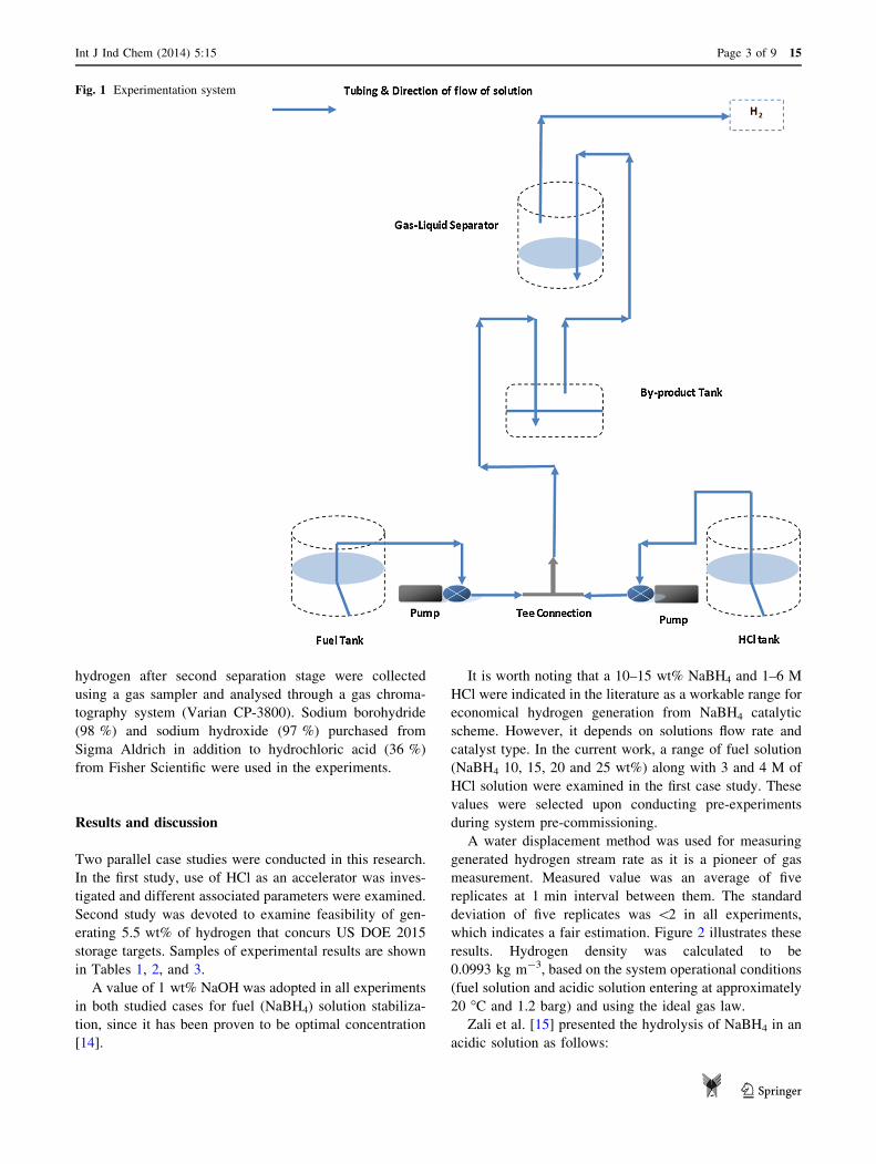
An experimental setup illustrated in Fig. 1 was applied in
the experiments. A simple hydrogen generation system was
designed to generate hydrogen at a controllable rate and to
obtain desired objectives. The main apparatus consisted of
fuel solution containers, followed by two peristaltic pumps,
a tee connection, product collector and a gas–liquid sepa-
rator. HCl and NaBH4 streams made a contact through a
Tee connection leading to an instantaneous hydrogen
generation along with by-products and excess water.
Sometimes, excess HCl was also observed in the product
solution. Product solution was collected in the product
collector and the hydrogen stream was passed through the
gas–liquid separator where the liquid phase was separated
and pure hydrogen gas was released from the system.
Peristaltic pumps of a single channel driven by AC motor
were used (Williamson manufacturing Co., UK), in which
a pump of 0.97 ml/min and another of 1.25 ml/min cali-
brated flow rate or vice versa were applied for feeding
NaBH4 and HCl solutions, respectively. In a later stage,
another peristaltic pump of 1.03 ml/min was applied for
NaBH4 solution feeding. Silicone tubing (1.6 mm ID) was
used throughout the setup for liquid and gas transportation.
Two glass containers of 80 ml were applied as two stages
gas–liquid separator. The aim was to purify generated
hydrogen stream from moisture and accompanied alkaline
mist based on a difference in density. Hydrogen generation
rate was calculated using a water displacement method
through a 250 ml glass cylinder. Samples of the generated
15 Page 2 of 9 Int J Ind Chem (2014) 5:15
123
hydrogen after second separation stage were collected
using a gas sampler and analysed through a gas chroma-
tography system (Varian CP-3800). Sodium borohydride
(98 %) and sodium hydroxide (97 %) purchased from
Sigma Aldrich in addition to hydrochloric acid (36 %)
from Fisher Scientific were used in the experiments.
Results and discussion
Two parallel case studies were conducted in this research.
In the first study, use of HCl as an accelerator was inves-
tigated and different associated parameters were examined.
Second study was devoted to examine feasibility of gen-
erating 5.5 wt% of hydrogen that concurs US DOE 2015
storage targets. Samples of experimental results are shown
in Tables 1, 2, and 3.
A value of 1 wt% NaOH was adopted in all experiments
in both studied cases for fuel (NaBH4) solution stabiliza-
tion, since it has been proven to be optimal concentration
[14].
It is worth noting that a 10–15 wt% NaBH4 and 1–6 M
HCl were indicated in the literature as a workable range for
economical hydrogen generation from NaBH4 catalytic
scheme. However, it depends on solutions flow rate and
catalyst type. In the current work, a range of fuel solution
(NaBH4 10, 15, 20 and 25 wt%) along with 3 and 4 M of
HCl solution were examined in the first case study. These
values were selected upon conducting pre-experiments
during system pre-commissioning.
A water displacement method was used for measuring
generated hydrogen stream rate as it is a pioneer of gas
measurement. Measured value was an average of five
replicates at 1 min interval between them. The standard
deviation of five replicates was \2 in all experiments,
which indicates a fair estimation. Figure 2 illustrates these
results. Hydrogen density was calculated to be
0.0993 kg m-3, based on the system operational conditions
(fuel solution and acidic solution entering at approximately
20 �C and 1.2 barg) and using the ideal gas law.
Zali et al. [15] presented the hydrolysis of NaBH4 in an
acidic solution as follows:
Fig. 1 Experimentation system
Int J Ind Chem (2014) 5:15 Page 3 of 9 15
123
BH�4 þ Hþ þ 3H2O! BðOHÞ3 þ 4H2 ð3Þ
Since the acidic hydrolysis is a relatively homogeneous
process (due to a controlled contact of two streams) and
excess water is available in the bulk, concentrations of
water and hydrogen are considered constant. Hence, the
kinetic equation of NaBH4 acidic hydrolysis is presented
by the following equation:
r ¼ d½NaBH4�dt
¼ k½NaBH4� ð4Þ
The authors [15] reported that a pseudo-first order
kinetic model fits the hydrogen generation from NaBH4
quite well. They concluded that a rate constant (k) of
0.003 s-1 well describes the hydrolysis reaction (acidic
scheme) with no catalyst. Accordingly, the activation
energy of the acidic hydrolysis can be estimated from
Arrhenius equation, considering a rate constant of
0.003 s-1 for a reaction bulk at 20 �C (at the contact point
of the streams), as follows:
k ¼ A expð�Ea=RTÞ ð5Þ
where A is the pre-exponential factor, Ea is the activation
energy and R is the gas constant.
Solving Eq. (5) for Ea gives a theoretical value of
10.87 kJ mol-1 for an acidic hydrolysis of NaBH4. Com-
paring this value with the literature shows that it equals one
eighth of a value 89 kJ mol-1 for a self-hydrolysis of
unbuffered–unstabilized 20 wt% NaBH4 solution [16],
whereas it approximately equals ten times the value
1.24 kJ mol-1 obtained when applying sulfonated porous
carbon catalyst [15].
It was observed at 3 M HCl that a maximum of 660 ml/
min and a minimum of 267 ml/min H2 stream rate were
obtained from 25 and 10 wt% NaBH4, respectively, from
applying a fuel solution rate of 0.97 ml/min. However, a
significant reduction in the hydrogen generation rate was
observed when the molarity of HCl solution was increased
to 4 M. After careful investigations, a modification was
tried in which the peristaltic pumps were exchanged and
consequently a highest hydrogen stream of 860 ml/min
from 25 wt% NaBH4 was obtained at a solution flowrate of
1.25 ml/min.
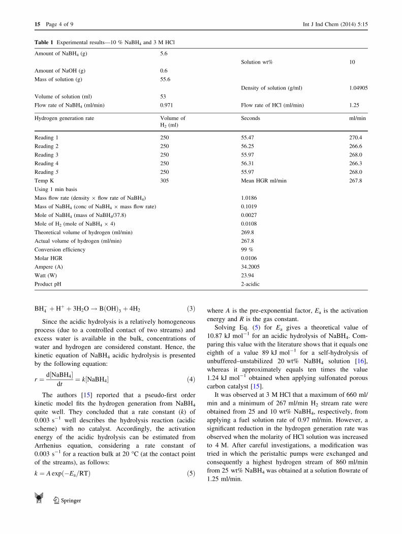
Table 1 Experimental results—10 % NaBH4 and 3 M HCl
Amount of NaBH4 (g) 5.6
Solution wt% 10
Amount of NaOH (g) 0.6
Mass of solution (g) 55.6
Density of solution (g/ml) 1.04905
Volume of solution (ml) 53
Flow rate of NaBH4 (ml/min) 0.971 Flow rate of HCl (ml/min) 1.25
Hydrogen generation rate Volume of
H2 (ml)
Seconds ml/min
Reading 1 250 55.47 270.4
Reading 2 250 56.25 266.6
Reading 3 250 55.97 268.0
Reading 4 250 56.31 266.3
Reading 5 250 55.97 268.0
Temp K 305 Mean HGR ml/min 267.8
Using 1 min basis
Mass flow rate (density 9 flow rate of NaBH4) 1.0186
Mass of NaBH4 (conc of NaBH4 9 mass flow rate) 0.1019
Mole of NaBH4 (mass of NaBH4/37.8) 0.0027
Mole of H2 (mole of NaBH4 9 4) 0.0108
Theoretical volume of hydrogen (ml/min) 269.8
Actual volume of hydrogen (ml/min) 267.8
Conversion efficiency 99 %
Molar HGR 0.0106
Ampere (A) 34.2005
Watt (W) 23.94
Product pH 2-acidic
15 Page 4 of 9 Int J Ind Chem (2014) 5:15
123
Somehow, researchers concluded that the hydrogen
generation rate proportionally increases with an increase of
NaBH4 concentration up to a certain point. After that point,
a reduction in the hydrogen generation rate was reported in
the work of [9, 14], and [17].
In the current study, a continuous increase in the
hydrogen generation rate was observed with a parallel
increase in NaBH4 concentration when using acidic scheme
and applying HCl as an acid accelerator, as presented in
Fig. 2. This result is partially related to the hydrogen
storage capacity which increases theoretically with a par-
allel increase in NaBH4 concentration fed to the system.
Additional reason could be a high conversion which
occurred as a result of an efficient direct contact between
fuel solution and acidic accelerator through a tee junction.
This result is in agreement with the findings of several
researchers [3, 10, 18]. They concluded that using NaBH4
in a solid form, while being injected through aqueous
acidified water, is more efficient than alkaline stabilized
form. They showed that an acidic scheme offers to pack
more hydrogen per unit volume of hydrogen generator,
while the mode of contact between two reacting species
would become much easier.
Other important observation was an increase in the
hydrogen generation rate upon parallel increases in fuel
concentration and feeding rate. This phenomenon has also
been observed by Kim et al. [3] up to such extent after
which a decrease was denoted in the hydrogen generation
rate and interpreted due to a shortage in the contact time
with the catalyst. Other researchers Subramanian and Javed
[18] and Kim et al. [3] applied controlled injections of fuel
solution into the hydrogen generator via syringe and pie-
zoelectric pumps, respectively, and indicated that better
hydrogen generation control was achieved. This clearly
illustrates that hydrogen production from NaBH4 using
HCl accelerator is highly controllable. Thereby, any
desired hydrogen generation rate could be obtained by
increasing or decreasing solution flow rates. This identity is
so beneficial for onboard fuel cell system applications and
ultimately the abovementioned results indicate that a pos-
sible amelioration in the hydrogen generation rate could be
achieved by applying higher NaBH4 concentrations and
using the proposed scheme as compared with the data
reported in the literature obtained via catalytic scheme.
With regards to the acid applied, the literature reported
that all acids facilitate an increase in the hydrogen yield
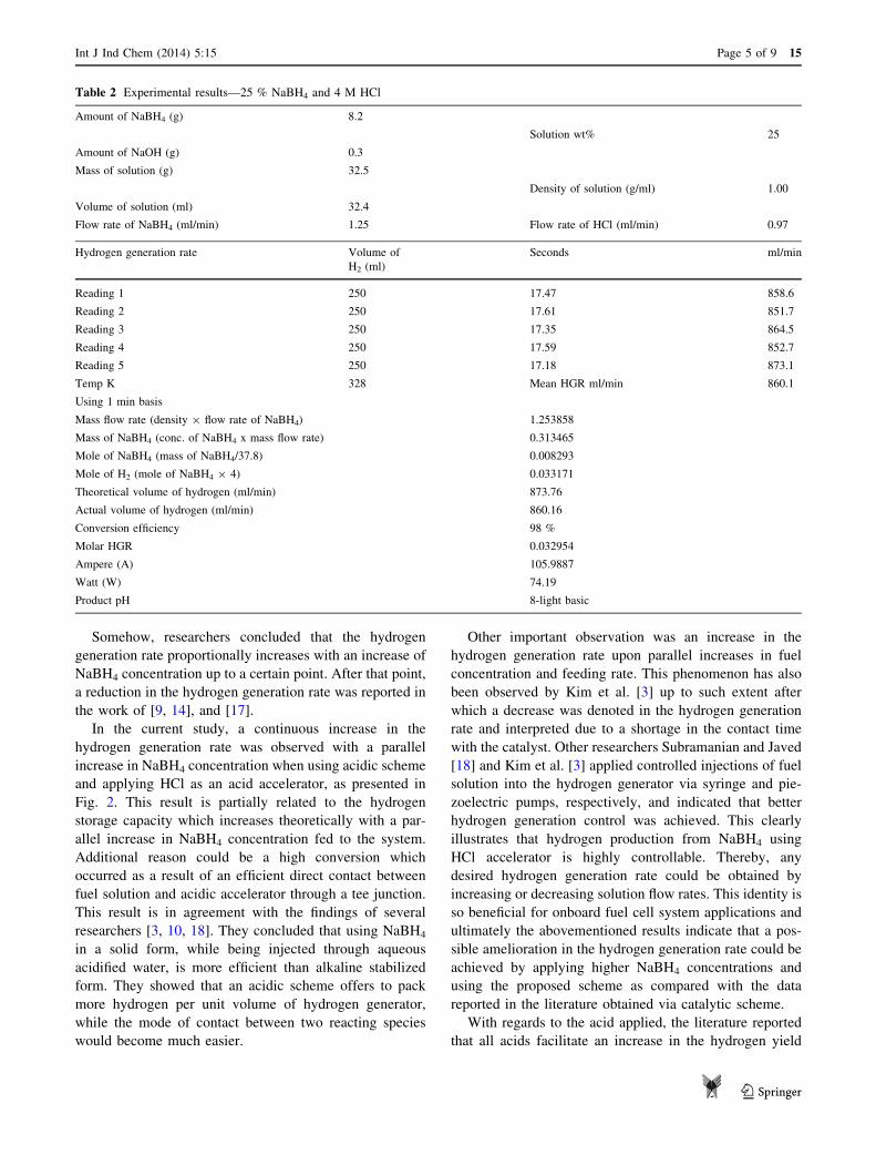
Table 2 Experimental results—25 % NaBH4 and 4 M HCl
Amount of NaBH4 (g) 8.2
Solution wt% 25
Amount of NaOH (g) 0.3
Mass of solution (g) 32.5
Density of solution (g/ml) 1.00
Volume of solution (ml) 32.4
Flow rate of NaBH4 (ml/min) 1.25 Flow rate of HCl (ml/min) 0.97
Hydrogen generation rate Volume of
H2 (ml)
Seconds ml/min
Reading 1 250 17.47 858.6
Reading 2 250 17.61 851.7
Reading 3 250 17.35 864.5
Reading 4 250 17.59 852.7
Reading 5 250 17.18 873.1
Temp K 328 Mean HGR ml/min 860.1
Using 1 min basis
Mass flow rate (density 9 flow rate of NaBH4) 1.253858
Mass of NaBH4 (conc. of NaBH4 x mass flow rate) 0.313465
Mole of NaBH4 (mass of NaBH4/37.8) 0.008293
Mole of H2 (mole of NaBH4 9 4) 0.033171
Theoretical volume of hydrogen (ml/min) 873.76
Actual volume of hydrogen (ml/min) 860.16
Conversion efficiency 98 %
Molar HGR 0.032954
Ampere (A) 105.9887
Watt (W) 74.19
Product pH 8-light basic
Int J Ind Chem (2014) 5:15 Page 5 of 9 15
123
with an increase in the acid concentration. Nonetheless, a
significant drop was observed with an addition of nitric
acid and phosphoric acid as compared to the hydrochloric
acid and sulphuric acid. Eventually, three acids were highly
recommended with their ideal concentrations which
include HCl at 3 N (yield 97 %), H2SO4 at 3 N (96 %
yield) and HCOOH at 12 N (87 % yield), [13]. More
concise, Demirci et al. [11] specified HCl as an acid of
choice for catalysing NaBH4 hydrolysis with very high
hydrogen generation rate.
HCl concentrations of 3 and 4 M were applied in the
current research. Both of them showed some exceptional
results and durability in terms of reaction and by-products
generation. However, a clear difference was observed in
the reactivity as 3 M solution was quite favourable yet
gave maximum conversion efficiency and the reaction was
highly controllable. On the other side, 4 M solution showed
a strong and vigorous reaction with NaBH4 which is
believed to be due to HCl reactivity. In terms of conversion
efficiency and hydrogen generation rate, HCl stream of
4 M concentration was found less competitive even after
pumps exchanged. Accordingly, 3 M of HCl is found to be
an optimal concentration in case of low NaBH4 concen-
tration, whilst 4 M concentration is recommended for high
NaBH4 concentration.
Table 3 Experimental results––30 % NaBH4 and 3 M HCl
Amount of NaBH4 (g) 10.6
Solution wt% 30
Amount of NaOH (g) 0.4
Mass of solution (g) 34.5
Density of solution (g/ml) 1.01
Volume of solution (ml) 34
Flow rate of NaBH4 (ml/min) 1.03 Flow rate of HCl (ml/min) 1.25
Hydrogen generation rate Volume of
H2 (ml)
Seconds ml/min
Reading 1 250 17.91 837.5
Reading 2 250 17.12 876.1
Reading 3 250 17.47 858.6
Reading 4 250 17.53 855.6
Reading 5 250 17.25 869.5
Temp K 324 Mean HGR ml/min 859.5
Using 1 min basis
Mass flow rate (density x flow rate of NaBH4) 1.045147
Mass of NaBH4 (conc. of NaBH4 x mass flow rate) 0.313544
Mole of NaBH4 (mass of NaBH4/37.8) 0.008295
Mole of H2 (mole of NaBH4 9 4) 0.033179
Theoretical volume of hydrogen (ml/min) 882.15
Actual volume of hydrogen (ml/min) 859.50
Conversion efficiency 97 %
Molar HGR 0.032962
Ampere (A) 106.0156
Watt (W) 74.21
Product pH 8-light basic
Fig. 2 Effect of NaBH4 concentrations on the hydrogen stream
generation rate at different fuel solution flow rates and accelerator
concentrations. HCl flow rates were 0.97 ml/min in case of 4 M and
1.25 ml/min in case of 3 M
15 Page 6 of 9 Int J Ind Chem (2014) 5:15
123
The efficiency of hydrogen generation was calculated
according to the following formula:
g ¼ Vactual
V theoretical� 100 ð6Þ
where;
Vactual = the actual hydrogen volume measured via
water displacement method.
Vtheoretical = volume of hydrogen estimated theoretically
according to Eq. (2), where 4 mol of hydrogen is generated
from decomposing 1 mol of NaBH4.
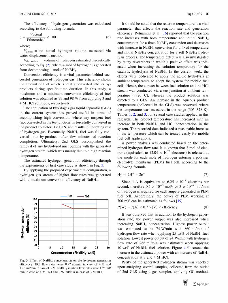
Conversion efficiency is a vital parameter behind suc-
cessful generation of hydrogen gas. This efficiency shows
the amount of fuel which is totally converted into its by-
products during specific time duration. In this study, a
maximum and a minimum conversion efficiency of fuel
solution was obtained as 99 and 98 % from applying 3 and
4 M HCl solutions, respectively.
The application of two stages gas liquid separator (GLS)
in the current system has proved useful in terms of
accomplishing high conversion, where any unspent fuel
(not converted in the tee junction) is forcefully converted in
the product collector, 1st GLS, and results in liberating rest
of hydrogen gas. Eventually, NaBH4 fuel was fully con-
verted into by-products after few minutes of reaction
completion. Ultimately, 2nd GLS accomplished the
removal of any hydrolysed mist coming with the generated
hydrogen stream, which was mainly due to a high reaction
temperature.
The estimated hydrogen generation efficiency through
the experiments of first case study is shown in Fig. 3.
By applying the proposed experimental configuration, a
hydrogen gas stream of higher flow rates was generated
with a maximum conversion efficiency of NaBH4.
It should be noted that the reaction temperature is a vital
parameter that affects the reaction rate and generation
efficiency. Retnamma et al. [16] reported that the reaction
rate increases with both temperature and initial NaBH4
concentration for a fixed NaBH4 conversion and decreases
with increase in NaBH4 conversion for a fixed temperature
and initial NaBH4 concentration for a self NaBH4 hydro-
lysis process. The temperature effect was also investigated
by many researchers in which a positive effect was indi-
cated when increasing the solution temperature for the
catalytic hydrolysis of NaBH4. In the current work, the
efforts were dedicated to apply the acidic hydrolysis at
ambient temperature to adopt the system for mobile fuel
cells. Hence, the contact between fuel solution and the HCl
stream was conducted via a tee junction at ambient tem-
perature (&20 �C), whereas the product solution was
directed to a GLS. An increase in the aqueous product
temperature (collected in the GLS) was observed, where
the temperature was measured in the range (305–328 K);
Tables 1, 2, and 3, for several case studies applied in this
research. The product temperature has increased with an
increase in both NaBH4 and HCl concentration in the
system. The recorded data indicated a reasonable increase
in the temperature which can be treated easily for mobile
fuel cell applications.
A power analysis was conducted based on the deter-
mined hydrogen flow rate. It is known that 2 mol of elec-
trons (equivalent to 12.04 9 1023 electrons) is released at
the anode for each mole of hydrogen entering a polymer
electrolyte membrane (PEM) fuel cell, according to the
following formula.
H2 ! 2Hþ þ 2e� ð7Þ
Since 1 A is equivalent to 6.25 9 1018 electrons per
second, therefore 0.5 9 10-5 mol/s or 3 9 10-4 mol/min
of hydrogen is required for each ampere generated in PEM
fuel cell. Accordingly, the power of PEM working at
700 mV can be estimated as follows [19]:
PðWÞ ¼ IðAÞ � 0:7 VðVÞ � efficiency ð8Þ
It was observed that in addition to the hydrogen gener-
ation rate, the power output was also increased when
increasing NaBH4 concentration. Highest power output
was estimated to be 74 W/min with 860 ml/min of
hydrogen flow rate when applying 25 wt% of NaBH4 fuel
solution. Lowest power output of 24 W/min with hydrogen
flow rate of 268 ml/min was estimated when applying
10 wt% of NaBH4 fuel solution. Figure 4 illustrates the
increase in the estimated power with an increase of NaBH4
concentration at 3 and 4 M HCl.
Purity of the generated hydrogen stream was checked
upon analysing several samples, collected from the outlet
of 2nd GLS using a gas sampler, applying GC method.
Fig. 3 Effect of NaBH4 concentration on the hydrogen generation
efficiency. HCl flow rates were 0.97 ml/min in case of 4 M and
1.25 ml/min in case of 3 M. NaBH4 solution flow rates were 1.25 ml/
min in case of 4 M HCl and 0.97 ml/min in case of 3 M HCl
Int J Ind Chem (2014) 5:15 Page 7 of 9 15
123
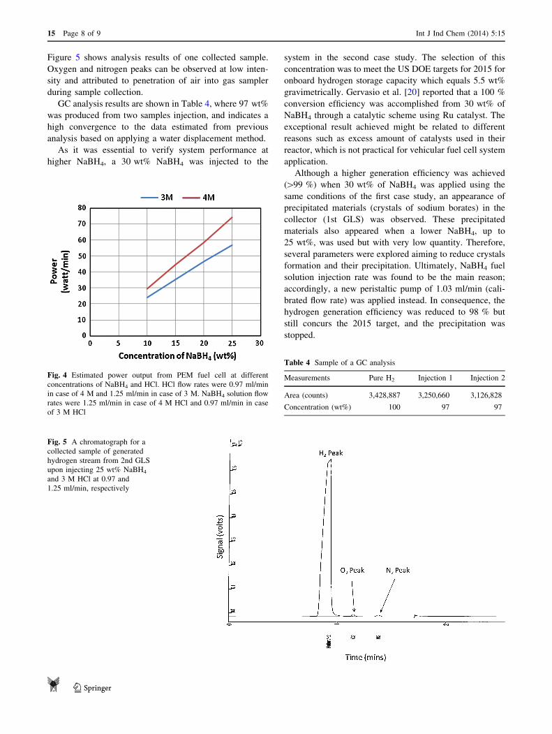
Figure 5 shows analysis results of one collected sample.
Oxygen and nitrogen peaks can be observed at low inten-
sity and attributed to penetration of air into gas sampler
during sample collection.
GC analysis results are shown in Table 4, where 97 wt%
was produced from two samples injection, and indicates a
high convergence to the data estimated from previous
analysis based on applying a water displacement method.
As it was essential to verify system performance at
higher NaBH4, a 30 wt% NaBH4 was injected to the
system in the second case study. The selection of this
concentration was to meet the US DOE targets for 2015 for
onboard hydrogen storage capacity which equals 5.5 wt%
gravimetrically. Gervasio et al. [20] reported that a 100 %
conversion efficiency was accomplished from 30 wt% of
NaBH4 through a catalytic scheme using Ru catalyst. The
exceptional result achieved might be related to different
reasons such as excess amount of catalysts used in their
reactor, which is not practical for vehicular fuel cell system
application.
Although a higher generation efficiency was achieved
([99 %) when 30 wt% of NaBH4 was applied using the
same conditions of the first case study, an appearance of
precipitated materials (crystals of sodium borates) in the
collector (1st GLS) was observed. These precipitated
materials also appeared when a lower NaBH4, up to
25 wt%, was used but with very low quantity. Therefore,
several parameters were explored aiming to reduce crystals
formation and their precipitation. Ultimately, NaBH4 fuel
solution injection rate was found to be the main reason;
accordingly, a new peristaltic pump of 1.03 ml/min (cali-
brated flow rate) was applied instead. In consequence, the
hydrogen generation efficiency was reduced to 98 % but
still concurs the 2015 target, and the precipitation was
stopped.
Fig. 4 Estimated power output from PEM fuel cell at different
concentrations of NaBH4 and HCl. HCl flow rates were 0.97 ml/min
in case of 4 M and 1.25 ml/min in case of 3 M. NaBH4 solution flow
rates were 1.25 ml/min in case of 4 M HCl and 0.97 ml/min in case
of 3 M HCl
Fig. 5 A chromatograph for a
collected sample of generated
hydrogen stream from 2nd GLS
upon injecting 25 wt% NaBH4
and 3 M HCl at 0.97 and
1.25 ml/min, respectively
Table 4 Sample of a GC analysis
Measurements Pure H2 Injection 1 Injection 2
Area (counts) 3,428,887 3,250,660 3,126,828
Concentration (wt%) 100 97 97
15 Page 8 of 9 Int J Ind Chem (2014) 5:15
123
It can be observed that the estimated hydrogen flow rate
(863 ml/min) generated from applying 30 % NaBH4 con-
centration at 1.03 ml/min fuel solution and 3 M HCl was
equivalent to a rate (860 ml/min) generated from applying
25 % NaBH4 at 1.25 ml/min and 3 M HCl, which means
that 74 W/min (4.44 kWh) is produced from both cases.
However, use of lower flow rate of fuel solution is indeed
more economical at large-scale systems and also advanta-
geous in terms of lowering liberated heat and by-products
crystallization and precipitation.
Conclusions
Two case studies were conducted to investigate feasibility
of using HCl scheme as an alternative to a catalytic scheme
for hydrogen generation from sodium borohydride system
serving vehicular fuel cells. The main objective was to
meet the DOE 2015 onboard hydrogen storage target
(5.5 wt%). Exceptional results showed that onboard mixing
of fuel and acidic streams in the proposed system of two
gas–liquid separators proved useful for higher conversion
efficiency and system performance. 98 % conversion effi-
ciency without any sodium borates precipitation was
achievable upon optimizing NaBH4 fuel solution flow rate.
Hence, a hydrogen generation rate of 863 ml/min was
obtained from applying 30 wt% NaBH4 at 1.03 ml/min and
3 M HCl at 0.97 ml/min, achieving 4.44 kWh of power.
Other important feature observed was reaction controlla-
bility, where it can be stopped by addition of alkaline
medium (e.g. sodium hydroxide) or accelerated by adding
acid.
Open Access This article is distributed under the terms of the
Creative Commons Attribution License which permits any use, dis-
tribution, and reproduction in any medium, provided the original
author(s) and the source are credited.
References
1. Hsu SE, Beibutian VM, Yeh MT (2001) Preparation of hydrogen
storage alloys for applications of hydrogen storage and trans-
portation. J Alloy Compd 330:882–885
2. Kikukawa S (2007) Consequence analysis and safety verification
of hydrogen fuelling stations using CFD simulation. Int J
Hydrogen Energy 33:1425–1434
3. Kim HJ et al (2010) Hydrogen generation from aqueous acid-
catalyzed hydrolysis of sodium borohydride. Int J Hydrogen
Energy 35:12239–12245
4. Demirci UB, Akdim O, Andrieux J, Hannauer J, Chamoun R,
Miele P (2010) Sodium borohydride hydrolysis as hydrogen
generator: issues, state of the art and applicability upstream from
a fuel cell. Fuel Cells 10(3):335–350
5. George L, Saxena SK (2010) Structural stability of metal
hydrides, alanates and borohydrides of alkali and alkali-earth
elements: a review. Int J Hydrogen Energy 35:5454–5470
6. US department of energy hydrogen program: Go/No-Go Rec-
ommendation for sodium borohydride for on-board vehicular
hydrogen storage—independent review, National Renewable
Energy Laboratory (2007). Last accessed 24 Dec 2013 on: http://
www.hydrogen.energy.gov/pdfs/42220.pdf
7. Schlesinger HI et al (1953) Sodium borohydride its hydrolysis
and its use as a reducing agent and in the generation of hydrogen.
J Chem Soc 7:215–219
8. Amendola SC et al (2000) A safe, portable, hydrogen gas gen-
erator using aqueous borohydride solution and Ru catalyst. Int J
Hydrogen Energy 25:969–975
9. Liang Y et al (2010) Hydrogen generation from sodium boro-
hydride solution using a ruthenium supported on graphite cata-
lyst. Int J Hydrogen Energy 35:3023–3028
10. Demirci UB, Miele P (2008) Sodium tetrahydroborate as energy/
hydrogen carrier, its history. C R Chim 12:943–950
11. Demirci UB et al (2009) Acetic acid, a relatively green single-use
catalyst for hydrogen generation from sodium borohydride. Int J
Hydrogen Energy 34:7231–7238
12. Demirci UB et al (2009) Highly efficient acid-treated cobalt
catalyst for hydrogen generation from NaBH4 hydrolysis. Int J
Hydrogen Energy 34:4780–4787
13. Subramanian V, Murugesan S (2009) Effects of acid accelerators
on hydrogen generation from solid sodium borohydride using
small scale devices. J Power Sources 187:216–223
14. Abdul-Majeed WS, Serdaroglu GM, Zimmerman WB (2012)
Application of liquid nitrogen cold trap for purification of
hydrogen gas stream generated from NaBH4. J Chem Chem Eng
6(5):425–434
15. Shokrolahi A, Zali A, Pouretedal HR (2012) Hydrogen genera-
tion from hydrolysis of sodium borohydride using sulfonated
porous carbon as reagent/catalyst. Iran J Catal 2(4):179–184
16. Retnamma et al. (2011) Kinetics of self-hydrolysis of concentrated
sodium borohydride solutions at high temperatures, International
Congress on Energy (2011 AIChE Annual Meeting). Last accessed
23 Dec 2013 on: http://repositorio.lneg.pt/bitstream/10400.9/1429/
1/Rajasree%20et%20al_%20AIChE_2011.pdf
17. Pinto AM et al (2006) Hydrogen generation and storage from
hydrolysis of sodium borohydride in batch reactors. Int J
Hydrogen Energy 3:1341–1347
18. Javed U, Subramanian V (2008) Hydrogen generation using a
borohydride-based semi-continuous milli-scale reactor: effects of
physicochemical parameters on hydrogen yield. Energy Fuels
23:408–413
19. Kojima Y et al (2004) Development of 10 kW-scale hydrogen
generator using chemical hydride. J Power Sources 125:22–26
20. Gervasio D et al (2005) Room temperature micro-hydrogen-
generator. J Power Sources 149:15–21
Int J Ind Chem (2014) 5:15 Page 9 of 9 15
123


![2014 "Miku’s Mask: Fictional Encounters in Children’s Costume Play". Article in Childhood: A Journal of Global Child Research [Open Access]](https://static.fdokumen.com/doc/165x107/631fbff415f75c9c2e0d0b22/2014-mikus-mask-fictional-encounters-in-childrens-costume-play-article.jpg)