Print this article - International Journal of Research
10
International Journal of Research Available at https://journals.pen2print.org/index.php/ijr/ e-ISSN: 2348-6848 p-ISSN: 2348-795X Volume 06 Issue 10 September 2019 Available online: https://journals.pen2print.org/index.php/ijr/ Page | 189 Analysis And Design Of Multistoried Building (G+6) Using E-Tabs And Slope Deflection Method A.RAMESH 1 K.VINOD 2 M.Tech (Structural Engineering) Assistant Professor (Civil engineering Department) DJR College of Engineering and Technology , Vijayawada. Andhra Pradesh. ABSTRACT :- The equations found for use in the Slope Deflection Method connect the rotations and displacements of a beam to the moments that are induced at its ends through forces. The elastic curve of a beam under a set of arbitrary forces is used to compare the differences in rotation of the beam to the angle of the chord. In this project slope deflection equations are applied to solve the statically indeterminate frames without sideway. In frames axial deformations are much smaller than the bending deformations and are neglected in the analysis. With this assumption the frames will not sideway. The frames will not be displaced to the right or left. The frames are properly restrained against sideway. The methods of three moment equation, and consistent deformation method are representing the force method of structural analysis, the slope deflection method use displacements as unknowns, hence this method is the displacement method. In this method, if the slopes at the ends and the relative displacement of the ends are known, the end moment can be found in terms of slopes, deflection, stiffness and length of the members. In order to compete in the ever growing competent market it is very important for a structural engineer to save time. As a sequel to this an attempt is made to analyze and design a multistoried building by using a software package E-TABS. For analyzing a multi -storied building one has to consider all the possible loadings and see that the structure is safe against all possible loading conditions. There are several methods for analysis of different frames like kani’s method, cantilever method, portal method, and Matrix method. The present project deals with the analysis and design of a multi storied residential building of G+6 the dead load &live loads are applied and the design for beams, columns, footing is obtained. KEY WORDS:E-Tabs 2015, IS Codes, Auto Cad 2016. I INTRODUCTION A. Overall In each characteristic of human development we desirable structures to live in or to get what we need. But it is not only Structure structures but to build efficient constructions so that it can fulfil the main persistence for what it was made for. Constructions derived in overall quantity of outlines and persistence’s, and have been improved during past for a wide number of factors, from Structure constituents presented, to with stand situations, to land- dwelling values, ground conditions, specific uses and aesthetic reasons. Assembly that has several floors above ground in the Structure Multi-storey Structures aim to advance the level area of the Structure without snowballing the area of the land the construction is built on, hence saving land and, in greatest cases, currency (contingent on material used and land prices in the area). The design process of multi-stored Structure requires not only imagination and academic
-
Upload
khangminh22 -
Category
Documents
-
view
1 -
download
0
Transcript of Print this article - International Journal of Research

International Journal of Research Available at https://journals.pen2print.org/index.php/ijr/
e-ISSN: 2348-6848 p-ISSN: 2348-795X Volume 06 Issue 10
September 2019
Available online: https://journals.pen2print.org/index.php/ijr/ P a g e | 189
Analysis And Design Of Multistoried Building (G+6) Using E-Tabs And Slope
Deflection Method
A.RAMESH
1 K.VINOD
2
M.Tech (Structural Engineering) Assistant Professor (Civil engineering Department)
DJR College of Engineering and Technology , Vijayawada. Andhra Pradesh.
ABSTRACT :- The equations found for use
in the Slope Deflection Method connect the
rotations and displacements of a beam to the
moments that are induced at its ends through
forces. The elastic curve of a beam under a set
of arbitrary forces is used to compare the
differences in rotation of the beam to the angle
of the chord.
In this project slope deflection equations are
applied to solve the statically indeterminate
frames without sideway. In frames axial
deformations are much smaller than the
bending deformations and are neglected in the
analysis. With this assumption the frames will
not sideway. The frames will not be displaced
to the right or left. The frames are properly
restrained against sideway. The methods of
three moment equation, and consistent
deformation method are representing the force
method of structural analysis, the slope
deflection method use displacements as
unknowns, hence this method is the
displacement method. In this method, if the
slopes at the ends and the relative
displacement of the ends are known, the end
moment can be found in terms of slopes,
deflection, stiffness and length of the
members.
In order to compete in the ever growing
competent market it is very important for a
structural engineer to save time. As a sequel to
this an attempt is made to analyze and design
a multistoried building by using a software
package E-TABS.
For analyzing a multi -storied building one has
to consider all the possible loadings and see
that the structure is safe against all possible
loading conditions. There are several methods
for analysis of different frames like kani’s
method, cantilever method, portal method, and
Matrix method.
The present project deals with the analysis and
design of a multi storied residential building
of G+6 the dead load &live loads are applied
and the design for beams, columns, footing is
obtained.
KEY WORDS:E-Tabs 2015, IS Codes, Auto
Cad 2016.
I INTRODUCTION
A. Overall
In each characteristic of human development
we desirable structures to live in or to get what
we need. But it is not only Structure structures
but to build efficient constructions so that it
can fulfil the main persistence for what it was
made for. Constructions derived in overall
quantity of outlines and persistence’s, and
have been improved during past for a wide
number of factors, from Structure constituents
presented, to with stand situations, to land-
dwelling values, ground conditions, specific
uses and aesthetic reasons. Assembly that has
several floors above ground in the Structure
Multi-storey Structures aim to advance the
level area of the Structure without
snowballing the area of the land the
construction is built on, hence saving land
and, in greatest cases, currency (contingent on
material used and land prices in the area). The
design process of multi-stored Structure
requires not only imagination and academic
International Journal of Research Available at https://journals.pen2print.org/index.php/ijr/
e-ISSN: 2348-6848 p-ISSN: 2348-795X Volume 06 Issue 10
September 2019
Available online: https://journals.pen2print.org/index.php/ijr/ P a g e | 190
discerning but also sound knowledge of
science of structural engineering besides the
knowledge of real-world aspects, such as
recent design codes, bye laws, sponsored up
by ample experience, intuition and judgment.
The persistence of values is to guarantee and
improve the safety, possession suspicious
stability between economy and safety. In the
modern study G plus 6 storey’s Structure at
Vidyanagar, Hyderabad, India is premeditated
(Slabs, Beams, Columns and Footings) using
E-Tabs software.
B. Introduction of Examination and Design
Examination: Examination of the structure
means to determination of the internal forces
like axial compression bending moment, shear
force etc. in the constituent associate aimed at
which the associate are near be calculated
below the accomplishment of given external
load.
Design: The design is process of section
percussion from the examination results by
using suitable examination method. The
purpose of design is to accomplishment of a
satisfactory likelihood that erections being
premeditated will perform satisfactorily
during their intended life.
Design of Structural Elements: The
innovativeness of any construction is
categorized into the following two main types:
Functional design and
Structural design.
Stages In Structural Design: The progression
of operational design encompasses the
succeeding stages:
Structural planning
Achievement of forces and calculation
of loads
Method of examination
Member design
Detailing, drawing and provision of
schedules
Introduction To Software: E-Tabs are a
software company with headquarters in
London, England. The company develops and
transports explosion mechanization responses
and amenities. The organization was
established in 1993 as ISPC by one of the
original organizers of Quantizes- specialist
Facts Dispensation software.
C. Objectives of Thesis
This thesis aims for relearning of concept of
structural design by the assistance of
processor aids. Momentarily we must go
concluded sub sequent opinions over the
proposition graft.
Sympathetic of project and specifying
idea.
Main detached i.e. learning of E-Tabs
software package.
Learning of examination and design
methodology which can be very useful
in the field.
Sympathetic of tremor confrontation
project notion.
Method for specialized rehearsal in the
arena of organizational manufacturing.
Carrying out a complete examination
and design of the main structural
elements of a multi-storey Structure
including slabs, columns, shear walls.
II LITERATURE REVIEW
Broad View:
Technique of inspection of statistically
uncategorized portal frames:
1. Method of flexibility coefficients.
2. Gradient dislocations procedures
(iterative methods)
3. Instant circulation technique
4. Kane’s method
5. Cantilever method
6. Portal method
7. Matrix method
Method of flexibility coefficients:
International Journal of Research Available at https://journals.pen2print.org/index.php/ijr/
e-ISSN: 2348-6848 p-ISSN: 2348-795X Volume 06 Issue 10
September 2019
Available online: https://journals.pen2print.org/index.php/ijr/ P a g e | 191
The scheme of checkup is covers reducing
the hyper static building to a determinate
structure form by Removing the redundant
sustenance (or) presenting satisfactory
scratches (or) cruxes.
Limitations:
It is not applicable for gradation of severance>3
Slope Displacement Comparisons:
It is valuable when kinematic indeterminacy
<standing indeterminacy. This process was
principal expressed by pin binge in 1914
founded on the requests of compatibility
and symmetry circumstances.
The technique originates its appellation
after the detail that provision slopes and
movements are openly comported. Set up
immediate reckonings is shaped the
explanation of these limits and the
combined instant in each component or
calculated from these standards.
Limitations:
A solution of simultaneous equations makes
methods tedious for manual computations.
This technique is not optional for borders
superior than too bays and two storeys.
Iterative approaches:
These procedures include allocating the
recognized secure and instants of the
organizational associate to head-to-head
associates at the junctions in order content
the circumstances of compatibility.
Boundaries of resistant irritated process:
It offerings certain problems once practical
to unbending edge particularly when the
edge is vulnerable to side power. The
technique cannot be functional to
constructions with in-between joints.
Kani’s technique:
These techniques ended originates particular
of the detriments of enduring irritated
technique. Kani’s method is alike to H.C.M
to that degree it too comprises recurrent
delivery of instants at consecutive joins in
edges and endures beams. Though here is a
main change in dissemination procedure of
two approaches. H.C.M allocates only the
total combined instant at any phase of
restatement. The greatest important mouth
of kani’s technique is that procedure of
repetition is self-corrective. Any mistake at
any phase of repetitions corrected in
following adders so skipping a few ladders
fault at any period of iteration is corrected
in subsequent consequently prancing a few
ladders of repetitions either by over vision
of by meaning fixes not lead to fault in last
end instants.
Compensations:
It is used for side way of frames.
Boundaries:
The turning of columns of any storey ought
to be operative a sole rotation charge of
equivalent storey. The beams of storey must
not experience revolution once the column
experiences paraphrase. That is the column
should be parallel. Borders through in-
between hinges cannot be inspection
Approximate method:
Approximate examination of hyper static
structure provides humble incomes of
procurement a fast. Explanation for initial
International Journal of Research Available at https://journals.pen2print.org/index.php/ijr/
e-ISSN: 2348-6848 p-ISSN: 2348-795X Volume 06 Issue 10
September 2019
Available online: https://journals.pen2print.org/index.php/ijr/ P a g e | 192
project it types certain abridging molds
regarding Organizational conduct so to get a
rapid explanation to multifaceted
constructions. The typical procedure
includes plummeting the assumed unknown
formation to a control structural scheme by
presenting passable not at all of pivots. It is
imaginable to draught the bounced outline
of the construction for the given loading and
hence by locates the print modulation
Subsequently each point of modulation
agrees to the position of zero instant in the
constructions. The modulation opinions can
be imagined as fulcrums for the
determination of inspection. The solution of
structures is split unassuming after the
variation ideas are placed. The stacking
belongings are ascending in multistoried
edges specifically flat and perpendicular
charging. The inspection approved out
unconnectedly for these two cases.
Flat Circumstances:
The performance of a construction exposed
to flat forces is contingent upon its statures
to breadth relation amid their issue. It is
compulsory it distinguish among little rise
then high rise edges in this circumstance.
Stumpy rise Constructions:
Height < width
It is considered predominately by shear
distortion.
High rise Constructions
Height > width
It is conquered by round about act
Matrix examination of frames:
The different essentials of mounts are afraid
per in changed instructions different persons
of lasts rays so their inspection is additional
multi-faceted not ever the fewer the
elementary suppleness and trouble methods
are applied to frames stiffness method is
more useful since its adaptability to
computer software design stiffness method
is used when degree of joblessness is better
than grade of freedom. Though difficulty
technique is rummage-sale grade of liberty
is better than grade of joblessness especially
for computers.
III METHODOLOGY & MATERIAL
The procedures of three moment equation,
and dependable distortion technique are
characterizing the FORCE METHOD of
organizational inspection, the Slope
Deflection method use displacements by way
of nonentities, henceforth this technique is
the displacement method. In this technique,
if the slopes at the conclusions and the
comparative displacement of the ends are
acknowledged, the end moment can be start
in relations of slopes, deflection, stiffness
and measurement of the members. In- the
slope-deflection method the turnings of the
links are dried as strangers. On behalf of
someone follower bounded by two
intersections the end moments can be
articulated in terms of revolutions. In this
method all joints are considered rigid; i.e. the
view point a midaffiliates at the joins are
measured not-to change in charge as loads
are functional, as shown in fig 1.
Joint conditions: to get θB & θC

International Journal of Research Available at https://journals.pen2print.org/index.php/ijr/
e-ISSN: 2348-6848 p-ISSN: 2348-795X Volume 06 Issue 10
September 2019
Available online: https://journals.pen2print.org/index.php/ijr/ P a g e | 193
A.Conventions In The Slope Deflection
Method
This system is founded on the subsequent
basic expectations. All the intersections of
the edge are rigid, i.e, the angle between the
associates at the joints do not alteration,
when the associates of edge are
encumbered. Falsification, owed to axial
and shear stresses, presence very small, are
mistreated.
Degree of Freedom: The number of
junction’s rotation and independent joint
translation in a structure is called the
degrees of freedom. Two types for degrees
of freedom.
In rotation
For beam or frame is equal to Dr.
Dr= j-f
Where:
Dr = degree of freedom.
j = no. of joints including
supports. F = no. of fixed
support.
The slop defection technique is appropriate for
beams and frames. It is useful for the
inspection of highly statically unknown
structures which have a low degree of
kinematical indeterminacy. For instance the
frame shown in fig. 2.a The frame (a) is nine
times statically indeterminate. On other hand
only two unknown rotations, θb and θc
i.e.cinematically indeterminate to additional
gradation- if the slope deflection is rummage-
sale. The edge (b) is once unstipulated.
B. Sign Conventions
Cooperative revolution& Fixed and instants
are measured optimistic once happening in a
right-handed route

International Journal of Research Available at https://journals.pen2print.org/index.php/ijr/
e-ISSN: 2348-6848 p-ISSN: 2348-795X Volume 06 Issue 10
September 2019
Available online: https://journals.pen2print.org/index.php/ijr/ P a g e | 194
Hence: MA = 2MB andθA =θA1 -θA2
Relation between Δ & M
IV EXAMINATION& STRUCTURAL
MODELLING
A. Overview
It is identical imperative to develop a
computational model on which linear / non-
linear, static/ dynamic checkup is achieved.
The main portion of these interval offerings
an immediate of various limitations
important the computational models, the
basic assumptions and the geometry of the
designated Structure considered for this
study. Accurate modeling of the nonlinear
properties of various structural elements is
very important in nonlinear examination. In
the present study, frame elements were
modeled with inelastic flexural hinges using
point plastic model. A detailed description
on the nonlinear modeling of RC frames is
presented. Infill walls are modeled as
equivalent diagonal strut elements. The last
part of the chapter deals with the
computational model of the equivalent strut
counting modeling nonlinearity.
B. Structure Description A framed Procedure located at
Hyderabad India (Seismic Zone -II) is
selected for the present-day study. The
Structure is objectively symmetric in plan
and in elevation.
International Journal of Research Available at https://journals.pen2print.org/index.php/ijr/
e-ISSN: 2348-6848 p-ISSN: 2348-795X Volume 06 Issue 10
September 2019
Available online: https://journals.pen2print.org/index.php/ijr/ P a g e | 195
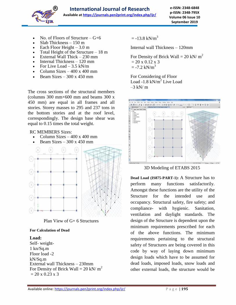
No. of Floors of Structure – G+6 Slab Thickness – 150 m Each Floor Height – 3.0 m Total Height of the Structure – 18 m External Wall Thick – 230 mm Internal Thickness – 120 mm For Live Load – 3.5 kN/m Column Sizes – 400 x 400 mm
Beam Sizes – 300 x 450 mm
The cross sections of the structural members
(columns 300 mm×600 mm and beams 300 x
450 mm) are equal in all frames and all
stories. Storey masses to 295 and 237 tons in
the bottom stories and at the roof level,
correspondingly. The design base shear was
equal to 0.15 times the total weight.
RC MEMBERS Sizes: Column Sizes – 400 x 400 mm Beam Sizes – 300 x 450 mm
Plan View of G+ 6 Structures
For Calculation of Dead
Load:
Self- weight-
1 kn/Sq.m
Floor load -2
kN/Sq.m External wall Thickness – 230mm For Density of Brick Wall = 20 kN/ m
2
= 20 x 0.23 x 3
= -13.8 kN/m3
Internal wall Thickness – 120mm
For Density of Brick Wall = 20 kN/ m2
= 20 x 0.12 x 3
= -7.2 kN/m3
For Considering of Floor
Load -1.8 kN/m2 Live Load
–3 kN/ m
3D Modeling of ETABS 2015
Dead Load (IS875-PART-1): A Structure has to
perform many functions satisfactorily.
Amongst these functions are the utility of the
Structure for the intended use and
occupancy. Structural safety, fire safety; and
compliance- with hygienic. Sanitation,
ventilation and daylight standards. The
design of the Structure is dependent upon the
minimum requirements prescribed for each
of the above functions. The minimum
requirements pertaining to the structural
safety of Structures are being covered in this
code by way of laying down minimum
design loads which have to be assumed for
dead loads, imposed loads, snow loads and
other external loads, the structure would be
International Journal of Research Available at https://journals.pen2print.org/index.php/ijr/
e-ISSN: 2348-6848 p-ISSN: 2348-795X Volume 06 Issue 10
September 2019
Available online: https://journals.pen2print.org/index.php/ijr/ P a g e | 196
required to bear. Strict conformity to loading
standards recommended in this code, it is
hoped. Will not only ensure the structural
safety of the Structures which are being
designed and constructed in the country and
thereby reduce the hazards to life and
property caused by unsafe structures, but
also eliminate the wastage caused by
assuming unnecessarily heavy loadings. This
Indian standard code of practice was first
published in 1957 for the guidance of civil
engineers, designers and architects
associated with planning and design of
Structures. It included the provisions for the
basic design loads (dead loads, live loads,
wind loads and seismic loads) to be assumed
in the design of Structures. In its first
revision in 1964, the wind pressure
provisions were modified on the basis of
studies of wind phenomenon and its effect
on structures, undertaken by the special
committee in consultation with the Indian
Meteorological Department. In addition to
this, new clauses on wind loads for butterfly
type structures were included; wind pressure
coefficients for sheeted roofs both curved
and sloping, were modified; seismic load
provisions were deleted (Separate code
having 3 been prepared) and metric system
of weights and measurements was adopted.
The increased adoptions of the code, a
number of comments were received on
provisions on live load values adopted for
different occupancies. Simultaneously, live
load surveys have been carried out in
America and Canada to arrive at realistic
live loads based on actual determination of
loading (movable and immovable) in
different occupancies. Keeping this in view
and other developments in the field of wind
engineering; the Sectional Committee
responsible for the preparation of the
standard has decided to prepare the second
revision in the following five parts:
Part 1 Dead loads
Part 2 Imposed loads
Part 3 Wind loads
Part 4 Snow loads
Part 5 Special loads and loads combinations
Earthquake load is covered in a separate
standard. Namely IS: 1893·1984· which
should be considered along with the above
loads. 0.4 This standard deals with dead
loads to be assumed in the design of
Structures and same is given in the- form of
unit weight of constituents. The unit
weights of other constituents that are likely
to be stored in a Structure are also included
for the persistence of load calculations due
to stored constituents, 0.4.1 this 'standard
incorporates IS: 1911t published in 1967.
The unit weight of constituents incorporated
in this standard are based on information
available through published Indian
standards and various other publications.
0.4.2 The values given in this standard have
been rounded off in accordance with IS: 2-
1960. "Criteria for earthquake resistant
design of structures (Third revision).
Schedule of unit weights of
Structureconstituent’s l fir SI revision).
Rules for rounding off numerical values.

International Journal of Research Available at https://journals.pen2print.org/index.php/ijr/
e-ISSN: 2348-6848 p-ISSN: 2348-795X Volume 06 Issue 10
September 2019
Available online: https://journals.pen2print.org/index.php/ijr/ P a g e | 197
Dead Load on G+ 6 Structures
3D Modeling of G+ 6 RC Framed Structures.
V CONCLUSIONS AND FUTURE SCOPE A. Conclusion
Usefulness of Additional frame
technique was checked under wind
forces.
It was found that substitute frame
method can be effectively applied for
examination of frames under wind
loads.
Wind forces can be neglected while
performing approximate examination by
Substitute frame method if the Structure
height is 14.7 m or less in both working
stress method as well as limit state
method.
In this proposition smooth borders
controlled against sideway are analyzed
using slope-deflection calculations.
Steadiness calculations are reproduced
at all rigid joint of the edge and also at
the support.
Few complications are unraveled to
illustrate the procedure. The shear force
and bending moment charts are pinched
for the close edges. B. Slope Deflection Examination (Sway
Case) Design wind pressure for the region
was assumed to be 1.5 kN/m2
Along with the vertical loads, the frame
was assumed to be resisting the wind
pressure for a length of 4m i.e. the
spacing between the frames was
assumed to be 4m.
Rotation contribution factors were same
as calculated in the vertical loading
case.
Restrained moments were calculated
again.
Same steps were then followed as in case
of vertical loading examination, repeating
the cycles till the values of near end
contributions converged.
Future Scope of Work: While execution
substitute frame method inspection, we can
try ignoring some of the far end spans just
to reduce the calculations further more.
Here is how it affected the end moments of
the 1st span when last spans were deducted
one by one.
VI. REFERENCESS
[1] G. Anil, Dr. P. SuvarnarRaju, D. A.
Raghavendra, International Journal of
Engineering and Applied Sciences (IJEAS),

International Journal of Research Available at https://journals.pen2print.org/index.php/ijr/
e-ISSN: 2348-6848 p-ISSN: 2348-795X Volume 06 Issue 10
September 2019
Available online: https://journals.pen2print.org/index.php/ijr/ P a g e | 198
ISSN: 2394-3661, Volume-3, Issue-4, April
2016 www.ijeas.org
[2] Prof.Sakshi A., Manchalwar, Akshay
S. Puri and Vishakha Aswale, International
Journal of Science, Engineering and
Technology Research (IJSETR), ISSN: 2278 –
7798, Volume 5, Issue 4, April 2016,
www.ijert.org
[3] BadgireUdhav S., Shaikh A.N., Maske
Ravi G.International Journal of Engineering
Research, ISSN:2319- 6890, Volume No.4,
Issue No.9, 01 Sept. 2015,
www.ijert.org
[4] Aman, ManjunathNalwadgi, Vishal T,
Gajendra, International Research Journal of
Engineering and Technology (IRJET), e-
ISSN: 2395 -0056, p-ISSN:
2395-0072, Volume: 03 Issue: 06, June-2016,
www.irjet.net
[5] SreekanthGandlaNanabala, Pradeep
Kumar Ramancharla, Arunakanthi E,
International Journal of Engineering Research
& Technology (IJERT), ISSN:
2278-0181, Vol. 3 Issue 9, September- 2014,
www.ijert.org
[6] Manual from CSI for using
SAP2000V17.3.