Joining 30 mm Thick Shipbuilding Steel Plates EH36 ... - MDPI
11
Citation: Gook, S.; Midik, A.; Biegler, M.; Gumenyuk, A.; Rethmeier, M. Joining 30 mm Thick Shipbuilding Steel Plates EH36 Using a Process Combination of Hybrid Laser Arc Welding and Submerged Arc Welding. J. Manuf. Mater. Process. 2022, 6, 84. https://doi.org/10.3390/ jmmp6040084 Academic Editor: Paul Kah Received: 6 July 2022 Accepted: 30 July 2022 Published: 4 August 2022 Publisher’s Note: MDPI stays neutral with regard to jurisdictional claims in published maps and institutional affil- iations. Copyright: © 2022 by the authors. Licensee MDPI, Basel, Switzerland. This article is an open access article distributed under the terms and conditions of the Creative Commons Attribution (CC BY) license (https:// creativecommons.org/licenses/by/ 4.0/). Manufacturing and Materials Processing Journal of Article Joining 30 mm Thick Shipbuilding Steel Plates EH36 Using a Process Combination of Hybrid Laser Arc Welding and Submerged Arc Welding Sergej Gook 1, * , Ahmet Midik 1 , Max Biegler 1 , Andrey Gumenyuk 2 and Michael Rethmeier 1,2,3 1 Fraunhofer Institute for Production Systems & Design Technology IPK, 10587 Berlin, Germany 2 Federal Institute of Materials Research and Testing (BAM), 12205 Berlin, Germany 3 Institute of Machine Tools and Factory Management, Technische Universität Berlin, 10587 Berlin, Germany * Correspondence: [email protected]; Tel.: +49-(30)39006375; Fax: +49-(30)3911037 Abstract: This article presents a cost-effective and reliable method for welding 30 mm thick sheets of shipbuilding steel EH36. The method proposes to perform butt welding in a two-run technique using hybrid laser arc welding (HLAW) and submerged arc welding (SAW). The HLAW is performed as a partial penetration weld with a penetration depth of approximately 25 mm. The SAW is carried out as a second run on the opposite side. With a SAW penetration depth of 8 mm, the weld cross-section is closed with the reliable intersection of both passes. The advantages of the proposed welding method are: no need for forming of the HLAW root; the SAW pass can effectively eliminate pores in the HLAW root; the high stability of the welding process regarding the preparation quality of the weld edges. Plasma cut edges can be welded without lack of fusion defects. The weld quality achieved is confirmed by destructive tests. Keywords: shipbuilding steel; hybrid laser arc welding; submerged arc welding; two-run welding technique; microstructure; hardness; bending test 1. Introduction The use of thick-walled steel plates is very common in industrial manufacturing. The main areas of application include the oil, gas and chemical industries. Other important fields of application are wind energy and shipbuilding. In offshore wind-turbine con- struction, for example, plates made of S355 steel with a thickness of up to 120 mm are used to construct the foundations [1]. In shipbuilding, demand for heavy plates with a good combination of high strength, toughness and weldability for the construction of large container ships has recently increased significantly. The successful application of a thermo- mechanical control process (TMCP) with the latest innovative alloying concepts has led to the development of EH36, EH40 and EH47 grade steel plates [2]. Alloying elements such as boron, copper and nickel have been added, and the rolling and cooling processes have been strongly and precisely controlled to improve strength and toughness simultaneously. ASTM A131 steel, grade EH36, for high heat input welding was successfully developed with good toughness at heat affected zones (HAZ) by increasing the thermal stability of TIN particles at high temperatures [3]. This high-strength steel is used extensively for struc- tural parts not only in shipbuilding but also in the oil and gas industry. For example, the Japanese steel manufacturer JFE offers TMCP steel plates for shipbuilding with a maximum thickness of 200 mm at a maximum width of 4 m [4]. The challenging aspect in terms of welding technology is that such thick-walled components can usually only be joined using multilayer arc-based welding processes, such as gas metal arc welding (GMAW) or submerged arc welding (SAW). This requires a very high welding time and increases manufacturing costs. At the same time, the heat input into the component is significant, which needs to be taken into account when processing J. Manuf. Mater. Process. 2022, 6, 84. https://doi.org/10.3390/jmmp6040084 https://www.mdpi.com/journal/jmmp
-
Upload
khangminh22 -
Category
Documents
-
view
3 -
download
0
Transcript of Joining 30 mm Thick Shipbuilding Steel Plates EH36 ... - MDPI

Citation: Gook, S.; Midik, A.; Biegler,
M.; Gumenyuk, A.; Rethmeier, M.
Joining 30 mm Thick Shipbuilding
Steel Plates EH36 Using a Process
Combination of Hybrid Laser Arc
Welding and Submerged Arc
Welding. J. Manuf. Mater. Process.
2022, 6, 84. https://doi.org/10.3390/
jmmp6040084
Academic Editor: Paul Kah
Received: 6 July 2022
Accepted: 30 July 2022
Published: 4 August 2022
Publisher’s Note: MDPI stays neutral
with regard to jurisdictional claims in
published maps and institutional affil-
iations.
Copyright: © 2022 by the authors.
Licensee MDPI, Basel, Switzerland.
This article is an open access article
distributed under the terms and
conditions of the Creative Commons
Attribution (CC BY) license (https://
creativecommons.org/licenses/by/
4.0/).
Manufacturing andMaterials Processing
Journal of
Article
Joining 30 mm Thick Shipbuilding Steel Plates EH36 Using aProcess Combination of Hybrid Laser Arc Welding andSubmerged Arc WeldingSergej Gook 1,* , Ahmet Midik 1, Max Biegler 1, Andrey Gumenyuk 2 and Michael Rethmeier 1,2,3
1 Fraunhofer Institute for Production Systems & Design Technology IPK, 10587 Berlin, Germany2 Federal Institute of Materials Research and Testing (BAM), 12205 Berlin, Germany3 Institute of Machine Tools and Factory Management, Technische Universität Berlin, 10587 Berlin, Germany* Correspondence: [email protected]; Tel.: +49-(30)39006375; Fax: +49-(30)3911037
Abstract: This article presents a cost-effective and reliable method for welding 30 mm thick sheets ofshipbuilding steel EH36. The method proposes to perform butt welding in a two-run technique usinghybrid laser arc welding (HLAW) and submerged arc welding (SAW). The HLAW is performed as apartial penetration weld with a penetration depth of approximately 25 mm. The SAW is carried out asa second run on the opposite side. With a SAW penetration depth of 8 mm, the weld cross-section isclosed with the reliable intersection of both passes. The advantages of the proposed welding methodare: no need for forming of the HLAW root; the SAW pass can effectively eliminate pores in theHLAW root; the high stability of the welding process regarding the preparation quality of the weldedges. Plasma cut edges can be welded without lack of fusion defects. The weld quality achieved isconfirmed by destructive tests.
Keywords: shipbuilding steel; hybrid laser arc welding; submerged arc welding; two-run weldingtechnique; microstructure; hardness; bending test
1. Introduction
The use of thick-walled steel plates is very common in industrial manufacturing. Themain areas of application include the oil, gas and chemical industries. Other importantfields of application are wind energy and shipbuilding. In offshore wind-turbine con-struction, for example, plates made of S355 steel with a thickness of up to 120 mm areused to construct the foundations [1]. In shipbuilding, demand for heavy plates with agood combination of high strength, toughness and weldability for the construction of largecontainer ships has recently increased significantly. The successful application of a thermo-mechanical control process (TMCP) with the latest innovative alloying concepts has led tothe development of EH36, EH40 and EH47 grade steel plates [2]. Alloying elements suchas boron, copper and nickel have been added, and the rolling and cooling processes havebeen strongly and precisely controlled to improve strength and toughness simultaneously.ASTM A131 steel, grade EH36, for high heat input welding was successfully developedwith good toughness at heat affected zones (HAZ) by increasing the thermal stability ofTIN particles at high temperatures [3]. This high-strength steel is used extensively for struc-tural parts not only in shipbuilding but also in the oil and gas industry. For example, theJapanese steel manufacturer JFE offers TMCP steel plates for shipbuilding with a maximumthickness of 200 mm at a maximum width of 4 m [4].
The challenging aspect in terms of welding technology is that such thick-walledcomponents can usually only be joined using multilayer arc-based welding processes, suchas gas metal arc welding (GMAW) or submerged arc welding (SAW). This requires a veryhigh welding time and increases manufacturing costs. At the same time, the heat inputinto the component is significant, which needs to be taken into account when processing
J. Manuf. Mater. Process. 2022, 6, 84. https://doi.org/10.3390/jmmp6040084 https://www.mdpi.com/journal/jmmp

J. Manuf. Mater. Process. 2022, 6, 84 2 of 11
high-strength fine-grain structural steels. Preheating or post-weld heat treatment leads toa considerable increase in manufacturing times and costs. An essential goal is, therefore,to keep the weld cross-section and the heat input as small as possible in order to achievetechnological advantages such as less distortion and residual stresses and better mechanical-technological properties [5].
The hybrid laser arc welding (HLAW) process is characterized by a higher penetrationdepth, a higher welding speed and a lower heat input and can thus be considered as analternative high-performance welding process for joining thick-walled structures. Repre-sentative examples from previous research show that a 16 mm thick pipe segment can behalf-orbital welded in a butt joint with a laser power of 19 kW at a relatively high weldingspeed of up to 2.2 m/min [6]. The 20 mm thick plates of API 5L X65 steel were successfullywelded with a laser power of 19 kW at a welding speed of 1.9 m/min [7]. The line energy ofthe HLAW process depends on the welding process parameters applied. In the single-passwelding of 20 mm thick sheets of API 5L X120 high-strength steel, the line energy rangedfrom 1.4 kJ/mm to 2.9 kJ/mm [8]. In the double-sided HLAW welding of 25 mm thickS690QL high-strength steel, successful welds with a penetration depth exceeding 15 mmwere obtained with line energies in the range between 1.7 kJ/mm and 2.4 kJ/mm [9]. Theprovided examples show that HLAW processes do not exceed the maximum line energiesof 3.5 ± 0.2 kJ/mm recommended by DIN EN 10225-1 [10] for fine-grained structural steelsin the offshore sector. On the other hand, the cooling time (∆t8/5) measured in the HAZand at the root side of HLAW welds on thick sheets made of high-strength steels is quiteshort and can be less than 1.0 s (cooling rate ≥ 300 ◦C/s) depending on the heat input fromthe welding process [11,12]. Such a short cooling time ∆t8/5 indicates a rather unfavorablewelding thermal cycle, which favors the formation of a brittle martensitic structure ofthe weld metal (WM). This fact can be seen as a limitation for the applicability of HLAWfor certain steel grades. Thus, an HLAW process design with an extended cooling time∆t8/5 appears to be of practical interest. As a reference, the recommended cooling ratesduring welding of high-strength low-alloy steels are in the range of 10 ◦C/s to 60 ◦C/s,corresponding to cooling times ∆t8/5 of between 30 s and 5 s [13–15].
Successful examples of the use of HLAW are known from shipbuilding, where sheetswith a thickness of up to 15 mm are joined at high speed and with lower distortion [16].There are initial research results for single-pass welding of up to 30 mm thick plates [17,18]or for double-side welding of up to 50 mm thick plates [19,20]. However, an industrialbreakthrough of high-power lasers for joining higher sheet thicknesses has not yet beenachieved due to process-specific limitations. First, it was found that the stability of theprocess decreased at higher laser powers. A scaling of the penetration depth and therequired laser power is not given above 20 kW laser power. Further limitations are dropletformation on the weld root, sensitivity to manufacturing tolerances such as gaps or edgemisalignment and deteriorated mechanical-technological properties, due to high coolingrates and inhomogeneous distribution of the filler metal over the entire weld depth.
Droplet formation during single-pass laser beam welding (LBW) and HLAW ofhigher plate thicknesses takes place due to the increasing hydrostatic pressure insidea keyhole [21–24]. A weld pool support is necessary to counteract this effect. The instal-lation and mechanical removal of the commercially available ceramic or copper backingsis uneconomical because it increases the production time. A contactless electromagneticweld pool support has been shown to be very effective in previous tests [25,26]. Currently,electromagnetic support systems are being further developed to be adapted for industrialmanufacturing conditions.
The aim of the present work is to investigate a cost-effective and reliable method forwelding 30 mm thick plates of high-strength, low-carbon steel. It is proposed to performbutt welding in two passes, using the HLAW method for the first pass and the SAW methodfrom the opposite side for the second pass. The main advantage of the proposed weldingmethod is its relatively simple implementation. It is not necessary to support the weld pooland form the root. The HLAW parameters are chosen in such a way that no full penetration

J. Manuf. Mater. Process. 2022, 6, 84 3 of 11
welding is achieved. The SAW pass intersects the HLAW pass and remelts any defects, suchas pores in the HLAW root. The weld quality achieved is examined by destructive testing.
2. Materials and Methods2.1. Materials
The base metal (BM) used was a commercial TMCP steel of grade EH36 according toASTM A131 with a plate thickness of 30 mm. The chemical composition of the used steel isshown in Table 1. Mechanical properties are listed in Table 2.
Table 1. Chemical composition of used steel EH36, shown in wt%.
C Si Mn P S Al N Nb
0.11 0.21 1.21 0.017 0.005 0.033 0.005 0.003
V Ti Cu Cr Ni Mo Fe Ceq *
0.071 0.017 0.01 0.03 0.01 0.001 bal. 0.33* Ceq = C + Mn/6 + (Ni + Cu)/15 + (Cr + Mo + V)/5.
Table 2. Mechanical properties of used steel EH36.
Charpy at −20 ◦Cin J
Yield Strengthin MPa
Ultimate Tensile Strengthin MPa
Elongationin %
283 503 555 22
The welding wire used for HLAW was Union K 52 Ni solid wire according to EN ISO14341-A: G 50 6 M21 Z3Ni1 with a diameter of 1.2 mm. The solid wire BA S2 according toEN ISO 14171-A (EN 756) with a diameter of 4 mm in combination with BF1 agglomeratedwelding flux of the aluminate rutile type was used for SAW. The gas mixture 18% CO2 inArgon with a flow rate of 20 L/min served as process gas for the HLAW.
For the laboratory tests, plates of EH36 with dimensions of 300 × 100 × 30 mm3 wereprepared for butt welding (Figure 1). This specimen size was determined based on thehandling techniques available in the laboratory. Previous experience with HLAW tests hasshown that a specimen length of at least 300 mm is sufficient to make a statement aboutthe weld seam quality. After subtracting the start and end crater area, about 250 mm ofthe weld length can still be used for further destructive and non-destructive testing. As arule, welding procedure qualification tests of welding procedures intended for the use forconstruction of marine structures are to be carried out in accordance with the recognizedstandards such as ISO, EN or requirements entailed by Classification Societies, such as:Bureau Veritas [27], Lloyd’s Register [28] or Det Norske Veritas (DNVGL) [29].
J. Manuf. Mater. Process. 2022, 6, x FOR PEER REVIEW 4 of 12
Figure 1. A 30 mm thick weld specimen EH36 with plasma cut edges.
Figure 2. Edge profile of plasma-cut plate made of low carbon high strength steel [30].
The interpretation of the measurement results states that the edge is inclined up-
wards (see section A-A in Figure 2) and this deflection is up to 2.7 mm. For this reason,
the edges of plasma-cut specimens are similar to a V-groove seam preparation.
2.2. Methods
The HLAW tests were performed using a 20 kW Yb fiber laser YLR 20000 of IPG. The
laser light was transmitted through an optical fiber of 200 μm in diameter. The laser optics
BIMO of HIGHYAG with a magnification factor of 2.8 and a focal length of 350 mm pro-
vided the focus diameter of the laser beam (df) of 0.56 mm. A welding machine,
QineoPulse 600 of Cloos, with a maximum current of 600 A was applied as a power source
for the arc. GMAW was performed with direct current of positive polarity (DC+). The
relatively high current and voltage values of the GMAW process ensured that an arc with
spray transfer mode was set. The wire feed speed (vf) was automatically adjusted accord-
ing to the synergy curve programmed in the welding machine. The laser optics and
GMAW torch were mounted on the robot arm, where the laser axis was positioned 90° to
the weld specimen surface and the GMA torch was tilted at an angle (γ) 25° relative to the
laser axis. All the experiments were carried out with an arc leading orientation and a dis-
tance (a) of 4 mm between the two heat sources. The focal position of the laser beam (∆z)
was −6 mm relative to the workpiece surface. The wire stick-out (S) was set to 18 mm. The
HLAW process configuration can be seen in Figure 3a.
Temperature measurements were performed on the top side of the specimens. For
this purpose, type K thermocouples were placed at a distance of approx. 4 mm to 6 mm
from the joint, which also made it possible to record the welding thermal cycle in the im-
mediate vicinity of the fusion zone (FZ). The high-temperature thermal paste was used to
protect the thermocouples against irradiation from the arc. The experimental setup for
HLAW tests with temperature-measurement system is shown in Figure 3b.
Figure 1. A 30 mm thick weld specimen EH36 with plasma cut edges.

J. Manuf. Mater. Process. 2022, 6, 84 4 of 11
The edge quality was plasma cut. The samples were prefabricated by the steel manu-facturer using a CNC plasma-cutting system. The reason for not using mechanical edgepreparation is that it provides welding conditions that can also be found in industry. Thus,there is no 0 mm gap between the workpieces. For the plasma-cut specimens, it is typicalthat the gap is nearly 0 mm at the bottom and that there is a slight V-shaped openingtowards the top. A better idea of the geometrical properties of the plasma-cut edges isgiven by own measurements on 20 mm thick sheets of high-strength low-alloy steel [30].The surface profile of the weld edges was measured with a scanCONTROL laser profilescanner (MICROEPSILON company). The edge profile scan is shown in Figure 2.
J. Manuf. Mater. Process. 2022, 6, x FOR PEER REVIEW 4 of 12
Figure 1. A 30 mm thick weld specimen EH36 with plasma cut edges.
Figure 2. Edge profile of plasma-cut plate made of low carbon high strength steel [30].
The interpretation of the measurement results states that the edge is inclined up-
wards (see section A-A in Figure 2) and this deflection is up to 2.7 mm. For this reason,
the edges of plasma-cut specimens are similar to a V-groove seam preparation.
2.2. Methods
The HLAW tests were performed using a 20 kW Yb fiber laser YLR 20000 of IPG. The
laser light was transmitted through an optical fiber of 200 μm in diameter. The laser optics
BIMO of HIGHYAG with a magnification factor of 2.8 and a focal length of 350 mm pro-
vided the focus diameter of the laser beam (df) of 0.56 mm. A welding machine,
QineoPulse 600 of Cloos, with a maximum current of 600 A was applied as a power source
for the arc. GMAW was performed with direct current of positive polarity (DC+). The
relatively high current and voltage values of the GMAW process ensured that an arc with
spray transfer mode was set. The wire feed speed (vf) was automatically adjusted accord-
ing to the synergy curve programmed in the welding machine. The laser optics and
GMAW torch were mounted on the robot arm, where the laser axis was positioned 90° to
the weld specimen surface and the GMA torch was tilted at an angle (γ) 25° relative to the
laser axis. All the experiments were carried out with an arc leading orientation and a dis-
tance (a) of 4 mm between the two heat sources. The focal position of the laser beam (∆z)
was −6 mm relative to the workpiece surface. The wire stick-out (S) was set to 18 mm. The
HLAW process configuration can be seen in Figure 3a.
Temperature measurements were performed on the top side of the specimens. For
this purpose, type K thermocouples were placed at a distance of approx. 4 mm to 6 mm
from the joint, which also made it possible to record the welding thermal cycle in the im-
mediate vicinity of the fusion zone (FZ). The high-temperature thermal paste was used to
protect the thermocouples against irradiation from the arc. The experimental setup for
HLAW tests with temperature-measurement system is shown in Figure 3b.
Figure 2. Edge profile of plasma-cut plate made of low carbon high strength steel [30].
The interpretation of the measurement results states that the edge is inclined upwards(see section A-A in Figure 2) and this deflection is up to 2.7 mm. For this reason, the edgesof plasma-cut specimens are similar to a V-groove seam preparation.
2.2. Methods
The HLAW tests were performed using a 20 kW Yb fiber laser YLR 20000 of IPG.The laser light was transmitted through an optical fiber of 200 µm in diameter. The laseroptics BIMO of HIGHYAG with a magnification factor of 2.8 and a focal length of 350 mmprovided the focus diameter of the laser beam (df) of 0.56 mm. A welding machine,QineoPulse 600 of Cloos, with a maximum current of 600 A was applied as a power sourcefor the arc. GMAW was performed with direct current of positive polarity (DC+). Therelatively high current and voltage values of the GMAW process ensured that an arc withspray transfer mode was set. The wire feed speed (vf) was automatically adjusted accordingto the synergy curve programmed in the welding machine. The laser optics and GMAWtorch were mounted on the robot arm, where the laser axis was positioned 90◦ to the weldspecimen surface and the GMA torch was tilted at an angle (γ) 25◦ relative to the laser axis.All the experiments were carried out with an arc leading orientation and a distance (a) of4 mm between the two heat sources. The focal position of the laser beam (∆z) was −6 mmrelative to the workpiece surface. The wire stick-out (S) was set to 18 mm. The HLAWprocess configuration can be seen in Figure 3a.
J. Manuf. Mater. Process. 2022, 6, x FOR PEER REVIEW 5 of 12
Figure 3. HLAW system: (a) process configuration; (b) experimental setup with temperature meas-
urement system.
The SAW tests were carried out in a large-scale welding facility for multi-wire SAW
on sheet metal and large pipes at Fraunhofer IPK in Berlin. Up to five arcs with a total
current of up to 7500 A can be used for SAW. The arcs were individually controlled and
supplied with welding current by five electronically controlled welding machines
PERFECTarc® 1500 AC/DC of SMS group GmbH.
3. Results
3.1. Hybrid Laser Arc Welding of 30 mm Plates EH36
The parameters of the HLAW process such as the laser power (PL), the arc power
(Parc) and the welding speed (vw) were selected so that no full penetration occurs. The
HLAW creates a partial penetrated weld that reaches almost to the bottom of the plate. As
a comparison of results in Figure 4 shows, such conditions could be achieved within a
wide parameter window.
Figure 4. Cross-sections of partial penetration HLAW seams performed with different process pa-
rameters: (a) lower welding speed und laser power; (b) higher welding speed und laser power.
AThe penetration depth of over 25 mm could be reached both for a slow vw = 0.6
m/min (Figure 4a) and for an increased vw = 1.15 m/min (Figure 4b). To compensate for
the decrease in the penetration depth when increasing the welding speed, it was necessary
to increase the laser power PL from 12 kW up to 15 kW. The arc power was kept constant
at Parc = 15.6 kW. The cooling time ∆t8/5 measured at the upper side of the sample was 12.5
s for the HLAW performed with vw = 0.6 m/min and 9.5 s for the HLAW performed with
vw = 1.15 m/min.
Figure 3. HLAW system: (a) process configuration; (b) experimental setup with temperature mea-surement system.
Temperature measurements were performed on the top side of the specimens. For thispurpose, type K thermocouples were placed at a distance of approx. 4 mm to 6 mm fromthe joint, which also made it possible to record the welding thermal cycle in the immediate

J. Manuf. Mater. Process. 2022, 6, 84 5 of 11
vicinity of the fusion zone (FZ). The high-temperature thermal paste was used to protectthe thermocouples against irradiation from the arc. The experimental setup for HLAW testswith temperature-measurement system is shown in Figure 3b.
The SAW tests were carried out in a large-scale welding facility for multi-wire SAW onsheet metal and large pipes at Fraunhofer IPK in Berlin. Up to five arcs with a total currentof up to 7500 A can be used for SAW. The arcs were individually controlled and suppliedwith welding current by five electronically controlled welding machines PERFECTarc®
1500 AC/DC of SMS group GmbH.
3. Results3.1. Hybrid Laser Arc Welding of 30 mm Plates EH36
The parameters of the HLAW process such as the laser power (PL), the arc power(Parc) and the welding speed (vw) were selected so that no full penetration occurs. TheHLAW creates a partial penetrated weld that reaches almost to the bottom of the plate. Asa comparison of results in Figure 4 shows, such conditions could be achieved within a wideparameter window.
J. Manuf. Mater. Process. 2022, 6, x FOR PEER REVIEW 5 of 12
Figure 3. HLAW system: (a) process configuration; (b) experimental setup with temperature meas-
urement system.
The SAW tests were carried out in a large-scale welding facility for multi-wire SAW
on sheet metal and large pipes at Fraunhofer IPK in Berlin. Up to five arcs with a total
current of up to 7500 A can be used for SAW. The arcs were individually controlled and
supplied with welding current by five electronically controlled welding machines
PERFECTarc® 1500 AC/DC of SMS group GmbH.
3. Results
3.1. Hybrid Laser Arc Welding of 30 mm Plates EH36
The parameters of the HLAW process such as the laser power (PL), the arc power
(Parc) and the welding speed (vw) were selected so that no full penetration occurs. The
HLAW creates a partial penetrated weld that reaches almost to the bottom of the plate. As
a comparison of results in Figure 4 shows, such conditions could be achieved within a
wide parameter window.
Figure 4. Cross-sections of partial penetration HLAW seams performed with different process pa-
rameters: (a) lower welding speed und laser power; (b) higher welding speed und laser power.
AThe penetration depth of over 25 mm could be reached both for a slow vw = 0.6
m/min (Figure 4a) and for an increased vw = 1.15 m/min (Figure 4b). To compensate for
the decrease in the penetration depth when increasing the welding speed, it was necessary
to increase the laser power PL from 12 kW up to 15 kW. The arc power was kept constant
at Parc = 15.6 kW. The cooling time ∆t8/5 measured at the upper side of the sample was 12.5
s for the HLAW performed with vw = 0.6 m/min and 9.5 s for the HLAW performed with
vw = 1.15 m/min.
Figure 4. Cross-sections of partial penetration HLAW seams performed with different processparameters: (a) lower welding speed und laser power; (b) higher welding speed und laser power.
AThe penetration depth of over 25 mm could be reached both for a slow vw = 0.6 m/min(Figure 4a) and for an increased vw = 1.15 m/min (Figure 4b). To compensate for the de-crease in the penetration depth when increasing the welding speed, it was necessary toincrease the laser power PL from 12 kW up to 15 kW. The arc power was kept constant atParc = 15.6 kW. The cooling time ∆t8/5 measured at the upper side of the sample was 12.5 sfor the HLAW performed with vw = 0.6 m/min and 9.5 s for the HLAW performed withvw = 1.15 m/min.
3.2. Submerged Arc Welding of 30 mm Plates EH36
After the EH36 plates were partially welded with HLAW, the SAW welds were per-formed from the opposite side of the specimens. The parameters of SAW were selectedto ensure sufficient penetration depth from one side and, thus, a reliable intersection ofthe SAW weld and the HLAW weld. From the other side, an economically interestingwelding speed of the SAW (vSAW) of above 1 m/min was aimed for. To meet these criteria,a three-wire SAW process was used. The main welding parameters are listed in Table 3.The arrangement of the welding torches to the specimen and the welding result are shownin Figure 5a,b.

J. Manuf. Mater. Process. 2022, 6, 84 6 of 11
Table 3. Parameters of three-wire SAW process.
vsaw inm/min
Electrode 1 (DC+) Electrode 2 (AC) Electrode 3 (AC)
I inA
U inV
vf inm/min
I inA
U inV
vf inm/min
I inA
U inV
vf inm/min
1.2 970 29 2.3 ± 0.2 640 34 0.9 ± 0.1 430 36 0.6 ± 0.1
J. Manuf. Mater. Process. 2022, 6, x FOR PEER REVIEW 6 of 12
3.2. Submerged Arc Welding of 30 mm Plates EH36
After the EH36 plates were partially welded with HLAW, the SAW welds were per-
formed from the opposite side of the specimens. The parameters of SAW were selected to
ensure sufficient penetration depth from one side and, thus, a reliable intersection of the
SAW weld and the HLAW weld. From the other side, an economically interesting welding
speed of the SAW (vSAW) of above 1 m/min was aimed for. To meet these criteria, a three-
wire SAW process was used. The main welding parameters are listed in Table 3. The ar-
rangement of the welding torches to the specimen and the welding result are shown in
Figure 5a,b.
Table 3. Parameters of three-wire SAW process.
vsaw
in m/min
Electrode 1 (DC+) Electrode 2 (AC) Electrode 3 (AC)
I in A U in V vf in
m/min I in A U in V
vf in
m/min I in A U in V
vf in
m/min
1.2 970 29 2.3 ± 0.2 640 34 0.9 ± 0.1 430 36 0.6 ± 0.1
Figure 5. Submerged arc welding of 30 mm plates EH36: (a) welding torch configuration; (b) outer
appearance of the three-wire SAW weld.
The cross-sections in Figure 6a,b show that the partially penetrated HLAW seams are
properly overlapped, resulting in a completely closed weld cross-section. The SAW layer
is free of undercuts and has a smooth transition from the base metal to the weld metal.
Figure 6. Cross-sections of partial penetration HLAW seams with SAW as opposite layers: (a)
HLAW layer performed with vw = 0.6 m/min; (b) HLAW layer performed with vw = 1.15 m/min.
Figure 5. Submerged arc welding of 30 mm plates EH36: (a) welding torch configuration; (b) outerappearance of the three-wire SAW weld.
The cross-sections in Figure 6a,b show that the partially penetrated HLAW seams areproperly overlapped, resulting in a completely closed weld cross-section. The SAW layer isfree of undercuts and has a smooth transition from the base metal to the weld metal.
J. Manuf. Mater. Process. 2022, 6, x FOR PEER REVIEW 6 of 12
3.2. Submerged Arc Welding of 30 mm Plates EH36
After the EH36 plates were partially welded with HLAW, the SAW welds were per-
formed from the opposite side of the specimens. The parameters of SAW were selected to
ensure sufficient penetration depth from one side and, thus, a reliable intersection of the
SAW weld and the HLAW weld. From the other side, an economically interesting welding
speed of the SAW (vSAW) of above 1 m/min was aimed for. To meet these criteria, a three-
wire SAW process was used. The main welding parameters are listed in Table 3. The ar-
rangement of the welding torches to the specimen and the welding result are shown in
Figure 5a,b.
Table 3. Parameters of three-wire SAW process.
vsaw
in m/min
Electrode 1 (DC+) Electrode 2 (AC) Electrode 3 (AC)
I in A U in V vf in
m/min I in A U in V
vf in
m/min I in A U in V
vf in
m/min
1.2 970 29 2.3 ± 0.2 640 34 0.9 ± 0.1 430 36 0.6 ± 0.1
Figure 5. Submerged arc welding of 30 mm plates EH36: (a) welding torch configuration; (b) outer
appearance of the three-wire SAW weld.
The cross-sections in Figure 6a,b show that the partially penetrated HLAW seams are
properly overlapped, resulting in a completely closed weld cross-section. The SAW layer
is free of undercuts and has a smooth transition from the base metal to the weld metal.
Figure 6. Cross-sections of partial penetration HLAW seams with SAW as opposite layers: (a)
HLAW layer performed with vw = 0.6 m/min; (b) HLAW layer performed with vw = 1.15 m/min. Figure 6. Cross-sections of partial penetration HLAW seams with SAW as opposite layers: (a) HLAWlayer performed with vw = 0.6 m/min; (b) HLAW layer performed with vw = 1.15 m/min.
The distances from the contact tip to the weld specimen (stick-out) were 35 mm for allwire electrodes and the distances between the electrodes were set at 15 mm and 10 mm. Thecalculated heat input of the three-wire SAW process was 3.27 kJ/mm and the deposition ratereached 22.5 kg/h. For comparison, a single-wire SAW provides a typical deposition rateof about 8 kg/h, with conventional welding speeds typically limited to 0.6 m/min [31,32].
J. Manuf. Mater. Process. 2022, 6, 84 7 of 11
The high deposition rate of the three-wire SAW process could be converted into a relativelyhigh welding speed of 1.2 m/min while maintaining the stability of the welding process.The leading electrode was supplied with direct current positive pole (DC+) to achievethe maximum weld penetration depth. The subsequent electrodes 2 and 3 were suppliedwith alternating current (AC) with a phase shift of 90◦ to minimize magnetic blowouteffects. The trailing angle of −5◦ of the leading electrode also had a favorable effect on thepenetration depth. With the selected welding parameters and torch configuration of theSAW process, a weld penetration depth of at least 7.7 mm was achieved.
3.3. Tests
Welds performed with an HLAW speed of vw = 0.6 m/min (Figure 6a) were selectedfor testing. The Vickers hardness test HV1 was performed according to DIN EN ISO6507-1 [33]. Hardness measurements were performed for both the HLAW and the SAWlayer. The distance between the hardness indentations was set to 1 mm to avoid anyinterferences between the results. Figure 7 provides some details on the location of thehardness measurement points in the weld cross-section.
J. Manuf. Mater. Process. 2022, 6, x FOR PEER REVIEW 7 of 12
The distances from the contact tip to the weld specimen (stick-out) were 35 mm for
all wire electrodes and the distances between the electrodes were set at 15 mm and 10 mm.
The calculated heat input of the three-wire SAW process was 3.27 kJ/mm and the deposi-
tion rate reached 22.5 kg/h. For comparison, a single-wire SAW provides a typical depo-
sition rate of about 8 kg/h, with conventional welding speeds typically limited to 0.6
m/min [31,32]. The high deposition rate of the three-wire SAW process could be converted
into a relatively high welding speed of 1.2 m/min while maintaining the stability of the
welding process. The leading electrode was supplied with direct current positive pole
(DC+) to achieve the maximum weld penetration depth. The subsequent electrodes 2 and
3 were supplied with alternating current (AC) with a phase shift of 90° to minimize mag-
netic blowout effects. The trailing angle of −5° of the leading electrode also had a favorable
effect on the penetration depth. With the selected welding parameters and torch configu-
ration of the SAW process, a weld penetration depth of at least 7.7 mm was achieved.
3.3. Tests
Welds performed with an HLAW speed of vw = 0.6 m/min (Figure 6a) were selected
for testing. The Vickers hardness test HV1 was performed according to DIN EN ISO 6507-
1 [33]. Hardness measurements were performed for both the HLAW and the SAW layer.
The distance between the hardness indentations was set to 1 mm to avoid any interfer-
ences between the results. Figure 7 provides some details on the location of the hardness
measurement points in the weld cross-section.
Figure 7. Location of the HV1 measurement points in the cross-section of the weld.
Observing of the individual hardness indentations shows that the highest hardness
values of 304 HV1 and 260 HV1 are located in the HAZ of the HLAW and SAW seams,
specifically in the fine-grain zone (FGHAZ) near the fusion line. Figure 8 shows the hard-
ness values as hardness profiles. Despite an increase in HAZ hardness by up to 90% above
the base material hardness, the maximum allowed hardness levels of 350 HV were not
exceeded [34].
The three-point side bend test was performed according to the ASME Section IX and
DIN EN ISO 5173 [35]. A total of six bend specimens (three specimens per weld) were
tested. The bending force was applied transverse to the welding direction so that the entire
weld profile was in tension. The side bend test confirmed the good ductility of the welds.
The specified bending angle of 180° was achieved for all specimens. Results of the bend
test are shown in Figure 9a–c. After testing, no irregularities, such as lack of fusion, cracks
and porosity in any direction, were found in the convex surface of the bent specimens.
Figure 7. Location of the HV1 measurement points in the cross-section of the weld.
Observing of the individual hardness indentations shows that the highest hardnessvalues of 304 HV1 and 260 HV1 are located in the HAZ of the HLAW and SAW seams,specifically in the fine-grain zone (FGHAZ) near the fusion line. Figure 8 shows thehardness values as hardness profiles. Despite an increase in HAZ hardness by up to 90%above the base material hardness, the maximum allowed hardness levels of 350 HV werenot exceeded [34].
J. Manuf. Mater. Process. 2022, 6, x FOR PEER REVIEW 8 of 12
Figure 8. Hardness profiles of HLAW and SAW layers.
Figure 9. Results of site bend test: (a) bent specimen in the three-point bending machine; (b) top
view of bent specimens; (c) convex surface of the bent specimen.
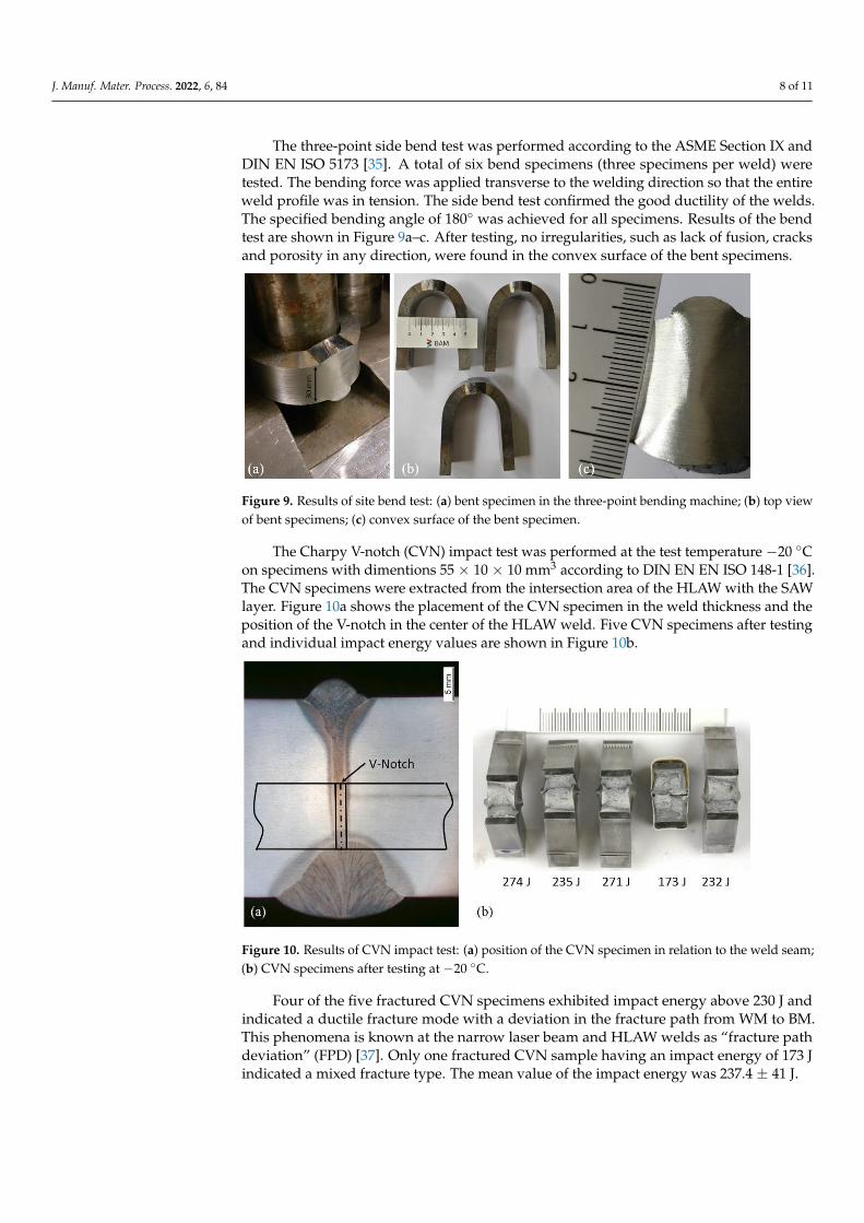
The Charpy V-notch (CVN) impact test was performed at the test temperature −20
°C on specimens with dimentions 55 × 10 × 10 mm3 according to DIN EN EN ISO 148-1
[36]. The CVN specimens were extracted from the intersection area of the HLAW with the
SAW layer. Figure 10a shows the placement of the CVN specimen in the weld thickness
and the position of the V-notch in the center of the HLAW weld. Five CVN specimens
after testing and individual impact energy values are shown in Figure 10b.
Figure 10. Results of CVN impact test: (a) position of the CVN specimen in relation to the weld
seam; (b) CVN specimens after testing at −20 °C.
Figure 8. Hardness profiles of HLAW and SAW layers.
J. Manuf. Mater. Process. 2022, 6, 84 8 of 11
The three-point side bend test was performed according to the ASME Section IX andDIN EN ISO 5173 [35]. A total of six bend specimens (three specimens per weld) weretested. The bending force was applied transverse to the welding direction so that the entireweld profile was in tension. The side bend test confirmed the good ductility of the welds.The specified bending angle of 180◦ was achieved for all specimens. Results of the bendtest are shown in Figure 9a–c. After testing, no irregularities, such as lack of fusion, cracksand porosity in any direction, were found in the convex surface of the bent specimens.
J. Manuf. Mater. Process. 2022, 6, x FOR PEER REVIEW 8 of 12
Figure 8. Hardness profiles of HLAW and SAW layers.
Figure 9. Results of site bend test: (a) bent specimen in the three-point bending machine; (b) top
view of bent specimens; (c) convex surface of the bent specimen.
The Charpy V-notch (CVN) impact test was performed at the test temperature −20
°C on specimens with dimentions 55 × 10 × 10 mm3 according to DIN EN EN ISO 148-1
[36]. The CVN specimens were extracted from the intersection area of the HLAW with the
SAW layer. Figure 10a shows the placement of the CVN specimen in the weld thickness
and the position of the V-notch in the center of the HLAW weld. Five CVN specimens
after testing and individual impact energy values are shown in Figure 10b.
Figure 10. Results of CVN impact test: (a) position of the CVN specimen in relation to the weld
seam; (b) CVN specimens after testing at −20 °C.
Figure 9. Results of site bend test: (a) bent specimen in the three-point bending machine; (b) top viewof bent specimens; (c) convex surface of the bent specimen.
The Charpy V-notch (CVN) impact test was performed at the test temperature −20 ◦Con specimens with dimentions 55 × 10 × 10 mm3 according to DIN EN EN ISO 148-1 [36].The CVN specimens were extracted from the intersection area of the HLAW with the SAWlayer. Figure 10a shows the placement of the CVN specimen in the weld thickness and theposition of the V-notch in the center of the HLAW weld. Five CVN specimens after testingand individual impact energy values are shown in Figure 10b.
J. Manuf. Mater. Process. 2022, 6, x FOR PEER REVIEW 8 of 12
Figure 8. Hardness profiles of HLAW and SAW layers.
Figure 9. Results of site bend test: (a) bent specimen in the three-point bending machine; (b) top
view of bent specimens; (c) convex surface of the bent specimen.
The Charpy V-notch (CVN) impact test was performed at the test temperature −20
°C on specimens with dimentions 55 × 10 × 10 mm3 according to DIN EN EN ISO 148-1
[36]. The CVN specimens were extracted from the intersection area of the HLAW with the
SAW layer. Figure 10a shows the placement of the CVN specimen in the weld thickness
and the position of the V-notch in the center of the HLAW weld. Five CVN specimens
after testing and individual impact energy values are shown in Figure 10b.
Figure 10. Results of CVN impact test: (a) position of the CVN specimen in relation to the weld
seam; (b) CVN specimens after testing at −20 °C.
Figure 10. Results of CVN impact test: (a) position of the CVN specimen in relation to the weld seam;(b) CVN specimens after testing at −20 ◦C.
Four of the five fractured CVN specimens exhibited impact energy above 230 J andindicated a ductile fracture mode with a deviation in the fracture path from WM to BM.This phenomena is known at the narrow laser beam and HLAW welds as “fracture pathdeviation” (FPD) [37]. Only one fractured CVN sample having an impact energy of 173 Jindicated a mixed fracture type. The mean value of the impact energy was 237.4 ± 41 J.

J. Manuf. Mater. Process. 2022, 6, 84 9 of 11
4. Discussion
In this work, a relatively high penetration depth of over 25 mm was achieved at mod-erate laser powers of 12 kW and 15 kW and welding speeds of 0.6 m/min and 1.15 m/min.Existing research results in the field of laser beam and laser hybrid welding on thick sheetsindicate that approximately one kilowatt of laser power is required for one millimeterof penetration depth [38]. This approach can be applied for butt joints with a zero gapand a material thickness up to 20 mm [7]. A linear correlation between laser power andweld penetration depth could not be confirmed for higher wall thicknesses. For example,welding tests with a laser power of 100 kW resulted in a maximum welding depth of70 mm, which corresponds to a penetration of 0.7 mm per 1 kW of laser power [39]. Whenusing special techniques such as welding under reduced ambient pressure or in a vacuum,the welding penetration depth can be significantly increased [40]. In the present work, apenetration depth of up to 2 mm per one kilowatt of laser power was achieved withoutusing any special welding techniques. This effect is due to the nature of the welding edge.The plasma-cut edge has a specific cutting profile that guarantees a V-shaped gap betweenthe weld pieces [30]. The laser beam penetrates through a butt joint with such a gap muchmore easily than through a full material. This observation was also confirmed for thelaser-cut edges, where HLAW could be performed in one pass on 25 mm thick steel withonly 14 kW of laser power [41]. Thus, the plasma-cut edge can be seen as advantageous forindustrial practice. On the one hand, the costly mechanical machining of the weld edges isnot necessary. On the other hand, higher productivity can be achieved due to the increasedpenetration depth.
Although all tested CVN specimens showed sufficient averaged impact energy of237.4 J, the dispersion of individual values ±41 J was relatively high. This is due to thefact that, with the same test parameters, the specimens behaved differently in the impacttest. Such differences in the impact energy of the HLAW welds can be explained by thenarrowness of the FZ as well as the grade of mechanical properties mismatch betweenthe FZ, HAZ and BM, which was indirectly confirmed by hardness measurements. Thehighest values obtained for the impact energy are due to the fact that the fracture occurswith FPD, with some volume of BM involved in the deformation process. This observationis consistent with the results of the study [37], in which the authors point out some reasonsfor the FPD formation. These are the narrowness of the FZ and low volume of the WMinvolved in the deformation process, asymmetry of the stress concentrator due to thespecific FZ shape and the presence of zones in the weld with softer metal. These factsfavor the crack propagating directly from the notch root into a softer BM throughout thethickness of the specimen. In some cases, the fracture occurs through the center of the WMwithout FPD. However, one of the conditions for this is an exact placement of the notch tipin the center of the FZ, which is not always possible when machining the CVN specimen.
In this study, HLAW tests were performed as partial penetration welding. It is knownfrom the previous studies that partially penetrated welds are more susceptible to theformation of the solidification cracks and pores than fully penetrated welds [42]. Theseimperfections typically occur in the middle or in the root region of the weld and are theresult of an interaction between metallurgical, geometric and thermomechanical factors.As the results of the present work show, any defects in the root of the HLAW seam canbe reliably remelted by the SAW layer, so that they no longer have any significance forthe functional safety of the component. The occurrence of crystallization cracks in thecenter of the weld can be counteracted by adjusting welding parameters such as arc power,defocusing of the laser beam and welding speed [43]. Since the aim of the present workwas to demonstrate the basic feasibility of the welding method, these aspects were notinvestigated in depth. They are the subject of the currently ongoing investigations.
5. Conclusions
Thirty mm thick sheets of shipbuilding steel EH36 were butt welded in a two-runtechnique using HLAW and SAW processes. The seam cross-section was completely filled

J. Manuf. Mater. Process. 2022, 6, 84 10 of 11
with a 25 mm deep HLAW layer and an approx. 8 mm deep SAW opposing layer. Theintersection of both layers was 3 mm. Thus, the potentially defective root of the partialpenetrated laser hybrid weld could be reliably remelted by the SAW layer.
A high stability of the welding process with regard to the preparation quality of theweld edges could be demonstrated. Thirty mm thick plates with plasma-cut edges couldbe welded without defects and with sufficient mechanical-technological properties.
The proposed method does not require mechanical processing of the weld edges andthere is no need for weld pool support. Therefore, the application of the proposed weldingmethod seems to be attractive for industrial use.
Author Contributions: Conceptualization, S.G, M.B., A.G. and M.R.; Formal analysis, A.M.; Investi-gation, A.M.; Methodology, S.G. and A.G.; Project administration, M.R.; Writing—original draft, S.G.and A.M.; Writing—review & editing, M.B., A.G. and M.R. All authors have read and agreed to thepublished version of the manuscript.
Funding: This work was supported by the Research Association for Steel Application (FOSTA),the Federation of Industrial Research Associations (AiF), and the German Federal Ministry forEconomic Affairs and Climate Action (BMWK Bundesministerium für Wirtschaft und Klimaschutz)(Project 21532N, “Combination of laser-hybrid welding and narrow-gap submerged arc welding forthick-walled components”).
Conflicts of Interest: The authors declare no conflict of interest.
References1. Schaumann, P.; Stranghöner, N.; Flügge, W. Stahlanwendungsforschung in der Windenergie. FOSTA. Available online: https:
//www.stahlforschung.de/media/50j-fosta-windenergie_1.pdf (accessed on 6 July 2022).2. Shirahata, H.; Nakashima, K.; Inoue, T.; Ishida, K.; Funatsu, Y.; Okawa, T.; Yanagita, K.; Inami, A.; Minagawa, M. YP 460 N/mm2
class heavy thick plate with excellent brittle crack arrestability for mega container ships. Nippon Steel Sumitomo Met. Tech. 2015,110, 25–29.
3. Um, K.K.; Kim, S.H.; Kang, K.B.; Park, Y.H.; Kwon, O. High performance steel plates for shipbuilding ap-plications. In Proceedingsof the Eighteenth International Offshore and Polar Engineering Conference, Vancouver, BC, Canada, 6–11 July 2008.
4. Steel Plates for Shipbuilding, JFE, Japan. Available online: https://www.jfe-steel.co.jp/en/products/plate/catalog/c1e-011.pdf(accessed on 3 July 2022).
5. Malin, V.Y. The State-of-the Art of Narrow Gap Welding Part II. Welding J. 1983, 62, 37–46.6. Gook, S.; Gumenyuk, A.; Rethmeier, M. Weld seam formation and mechanical properties of girth welds performed with
laser-GMA-hybrid process on pipes of grade X65. In Proceedings of the International Congress on Applications of Lasers &Electro-Optics, Anaheim, CA, USA, 26–30 September 2010; Volume 2010, pp. 62–69.
7. Rethmeier, M.; Gook, S.; Lammers, M.; Gumenyuk, A. Laser-Hybrid Welding of Thick Plates up to 32 mm Using a 20 kW FibreLaser. Q. J. Jpn. Weld. Soc. 2009, 27, 74s–79s. [CrossRef]
8. Üstündag, Ö.; Gook, S.; Gumenyuk, A.; Rethmeier, M. Hybrid laser arc welding of thick high-strength pipeline steels of gradeX120 with adapted heat input. J. Mater. Process. Technol. 2019, 275, 116358. [CrossRef]
9. Sørensen, C.; Nissen, A.; Brynning, C.; Nielsen, J.; Schøn, R.; Malefijt, R.; Kristiansen, M. Double-sided Hybrid Laser-Arc Weldingof 25 mm S690QL High Strength Steel. IOP Conf. Ser. Mater. Sci. Eng. 2021, 1135. [CrossRef]
10. DIN EN 10225-1; Weldable Structural Steels for Fixed Offshore Structures-Technical Delivery Conditions-Part 1: Plates. BeuthVerlag: Beuth, Germany, 2019.
11. Turichin, G.; Kuznetsov, M.; Pozdnyakov, A.; Gook, S.; Gumenyuk, A.; Rethmeier, M. Influence of heat input and preheating onthe cooling rate, microstructure and mechanical properties at the hybrid laser-arc welding of API 5L X80 steel. Procedia CIRP 2018,74, 748–751. [CrossRef]
12. Wang, G.; Wang, J.; Yin, L.; Hu, H.; Yao, Z. Quantitative Correlation between Thermal Cycling and the Microstructures of X100Pipeline Steel Laser-Welded Joints. Materials 2019, 13, 121. [CrossRef] [PubMed]
13. Knoop, F.M.; Bremer, S.; Flaxa, V.; Scheller, W.; Liedtke, M. The processing of helical-welded large diameter pipes of grade X80with 23.7 mm wall thickness and their properties. In Proceedings of the International Seminar on Welding of High StrengthPipeline Steels, Araxa, Brazil, 28–30 November 2011; pp. 209–229.
14. Frantov, I.; Permyakov, I.; Bortsov, A. Improved weldability and criterion for reliability of high strength pipes steels. InProceedings of the International Seminar on Welding of High Strength Pipeline Steels, Araxa, Brazil, 28–30 November 2011;pp. 247–260.
15. Shang, C.J.; Wang, X.X.; Liu, Q.Y.; Fu, J.Y. Weldability of high niobium X80 pipeline steel. In Proceedings of the InternationalSeminar on Welding of High Strength Pipeline Steel, Araxa, Brazil, 28–30 November 2011; Volume 435, p. 453.

J. Manuf. Mater. Process. 2022, 6, 84 11 of 11
16. Roland, F.; Manzon, L.; Kujala, P.; Brede, M.; Weitzenbock, J. Advanced Joining Techniques in European Shipbuilding. J. Ship Prod.2004, 20, 200–210. [CrossRef]
17. Üstündag, Ö.; Avilov, V.; Gumenyuk, A.; Rethmeier, M. Full penetration hybrid laser arc welding of up to 28 mm thick S355plates using electromagnetic weld pool support. J. Phys. Conf. Ser. 2018, 1109, 012015. [CrossRef]
18. Üstündag, Ö.; Gumenyuk, A.; Rethmeier, M. Single-pass Hybrid Laser Arc Welding of Thick Materials Using ElectromagneticWeld Pool Support. In Proceedings of the International WLT-Conference on Lasers in Manufacturing, Munich, Germany,23–26 May 2019.
19. Wahba, M.; Mizutani, M.; Katayama, S. Single pass hybrid laser-arc welding of 25 mm thick square groove butt joints. Mater. Des.2016, 97, 1–6. [CrossRef]
20. Reisgen, U.; Olschok, S.; Engels, O. Laser beam submerged arc hybrid welding: A novel hybrid welding process. J. Laser Appl.2018, 30, 042012. [CrossRef]
21. Üstündag, Ö.; Gook, S.; Gumenyuk, A.; Rethmeier, M. Mechanical Properties of Single-pass Hybrid Laser Arc Welded 25 mmThick-walled Structures Made of Fine-grained Structural Steel. Procedia Manuf. 2019, 36, 112–120. [CrossRef]
22. Frostevarg, J.; Heussermann, T. Dropout formation in thick steel plates during laser welding. In Proceedings of the IIWInternational Conference on High Strength Materials–Challenges and Applications, Helsinki, Finland, 2–3 July 2015.
23. Suder, W.; Ganguly, S.; Williams, S.; Yudodibroto, B. Root stability in hybrid laser welding. J. Laser Appl. 2017, 29, 022410.[CrossRef]
24. Bunaziv, I.; Dørum, C.; Nielsen, S.E.; Suikkanen, P.; Ren, X.; Nyhus, B.; Eriksson, M.; Akselsen, O.M. Root formation andmechanical properties in laser keyhole welding of 15 mm thick HSLA steel. IOP Conf. Ser. Mater. Sci. Eng. 2021, 1135. [CrossRef]
25. Üstündag, Ö.; Fritzsche, A.; Avilov, V.; Gumenyuk, A.; Rethmeier, M. Hybrid laser-arc welding of thick-walled ferromagneticsteels with electromagnetic weld pool support. Weld. World 2018, 62, 767–774. [CrossRef]
26. Avilov, V.V.; Gumenyuk, A.; Lammers, M.; Rethmeier, M. PA position full penetration high power laser beam welding of up to 30mm thick AlMg3 plates using electromagnetic weld pool support. Sci. Technol. Weld. Join. 2012, 17, 128–133. [CrossRef]
27. BV NR 216 DT R07 E; BV Rules on Materials and Welding for the Classification of Marine Units. Bureau Veritas: Paris, France,2018; Volume 33.
28. Lloyd’s Register Group. Rules for the Manufacture, Testing and Certification of Materials; Lloyd’s Register: London, UK, 2017.29. DNVGL-CG-0287; Hybrid Laser-Arc Welding. DNVGL: Oslo, Norway, 2015.30. Üstündag, Ö.; Bakir, N.; Gook, S.; Gumenyuk, A.; Rethmeier, M. Hybrid laser-arc welding of laser- and plasma-cut 20-mm-thick
structural steels. Weld. World 2022, 66, 507–514. [CrossRef]31. Layus, P.; Kah, P.; Gezha, V. Advanced submerged arc welding processes for Arctic structures and ice-going vessels. Proc. Inst.
Mech. Eng. Part B J. Eng. Manuf. 2016, 232, 114–127. [CrossRef]32. Chandel, R.; Seow, H.; Cheong, F. Effect of increasing deposition rate on the bead geometry of submerged arc welds. J. Mater.
Process. Technol. 1997, 72, 124–128. [CrossRef]33. DIN EN ISO 6507-1; Metallic Materials-Vickers Hardness Test-Part 1: Test Method. Deutsches Institut fur Normung E.V. (DIN):
Beuth, Germany, 2022.34. DIN EN ISO 15614-1; Specification and Qualification of Welding Procedures for Metallic Materials-Welding Procedure Test-Part 1:
Arc and Gas Welding of Steels and Arc Welding of Nickel and Nickel Alloys. Deutsches Institut fur Normung E.V. (DIN): Beuth,Germany, 2020.
35. DIN EN ISO 5173; Destructive Tests on Welds in Metallic Materials—Bend Tests. Deutsches Institut fur Normung E.V. (DIN):Beuth, Germany, 2021.
36. DIN EN ISO 148-1; Metallic Materials-Charpy Pendulum Impact Test-Part 1: Test Method. Deutsches Institut fur Normung E.V.(DIN): Beuth, Germany, 2017.
37. Ohata, M.; Morimoto, G.; Fukuda, Y.; Minami, F.; Inose, K.; Handa, T. Prediction of ductile fracture path in Charpy V-notchspecimen for laser beam welds. Weld. World 2015, 59, 667–674. [CrossRef]
38. Paes, L.E.D.S.; Pereira, M.; Weingaertner, W.L.; Scotti, A.; Souza, T. Comparison of methods to correlate input parameters withdepth of penetration in LASER welding. Int. J. Adv. Manuf. Technol. 2018, 101, 1157–1169. [CrossRef]
39. Kawahito, Y.; Wang, H.; Katayama, S.; Sumimori, D. Ultra high power (100 kW) fiber laser welding of steel. Opt. Lett. 2018,43, 4667–4670. [CrossRef] [PubMed]
40. Katayama, S.; Yohei, A.; Mizutani, M.; Kawahito, Y. Development of Deep Penetration Welding Technology with High BrightnessLaser under Vacuum. Phys. Procedia 2011, 12, 75–80. [CrossRef]
41. Farrokhi, F.; Larsen, R.M.; Kristiansen, M. Single-pass Hybrid Laser Welding of 25 mm Thick Steel. Phys. Procedia 2017, 89, 49–57.[CrossRef]
42. Gebhardt, M.O.; Gumenyuk, A.; Rethmeier, M. Solidification cracking in laser GMA hybrid welding of thick-walled parts. Sci.Technol. Weld. Join. 2013, 19, 209–213. [CrossRef]
43. Bakir, N.; Üstündag, Ö.; Gumenyuk, A.; Rethmeier, M. Experimental and numerical study on the influence of the laser hybridparameters in partial penetration welding on the solidification cracking in the weld root. Weld. World 2020, 64, 501–511. [CrossRef]