No.47 Shipbuilding and Repair Quality Standard
43
- 1 - No.47 Shipbuilding and Repair Quality Standard (1996) (Rev. 1, 1999) (Rev.2, Dec. 2004) (Rev.3, Nov. 2006) (Rev.4, Aug. 2008) (Rev.5, Oct. 2010) Part A Shipbuilding and Remedial Quality Standard for New Construction Part B Repair Quality Standard for Existing Ships PART A - SHIPBUILDING AND REMEDIAL QUALITY STANDARDS FOR NEW CONSTRUCTION 1. Scope 2. General requirements for new construction 3. Qualification of personnel and procedures 3.1 Qualification of welders 3.2 Qualification of welding procedures 3.3 Qualification of NDE operators 4. Materials 4.1 Materials for structural members 4.2 Surface conditions 5. Gas Cutting 6. Fabrication and fairness 6.1 Flanged longitudinals and flanged brackets 6.2 Built-up sections 6.3 Corrugated bulkheads 6.4 Pillars, brackets and stiffeners 6.5 Maximum heating temperature on surface for line heating 6.6 Block assembly 6.7 Special sub-assembly 6.8 Shape 6.9 Fairness of plating between frames 6.10 Fairness of plating with frames 6.11 Preheating for welding hull steels at low temperature 7. Alignment 8. Welding Joint Details 8.1 Typical butt weld plate edge preparation (manual welding and semi-automatic welding) 8.2 Typical fillet weld plate edge preparation (manual welding and semi-automatic welding) 8.3 Butt and fillet weld profile (manual welding and semi-automatic welding) 8.4 Typical butt weld edge preparation (Automatic welding) 8.5 Distance between welds 9. Remedial 9.1 Typical misalignment remedial 9.2 Typical butt weld plate edge preparation remedial (manual welding and semi-automatic welding) 9.3 Typical fillet weld plate edge preparation remedial (manual welding and semi-automatic welding) 9.4 Typical fillet and butt weld profile remedial (manual welding and semi-automatic welding) 9.5 Distance between welds remedial 9.6 Erroneous hole remedial 9.7 Remedial by insert plate 9.8 Weld surface remedial 9.9 Weld remedial (short bead)
-
Upload
khangminh22 -
Category
Documents
-
view
1 -
download
0
Transcript of No.47 Shipbuilding and Repair Quality Standard
- 1 -
No.47 Shipbuilding and Repair Quality Standard (1996) (Rev. 1, 1999) (Rev.2, Dec. 2004) (Rev.3, Nov. 2006) (Rev.4, Aug. 2008) (Rev.5, Oct. 2010)
Part A Shipbuilding and Remedial Quality Standard for New Construction
Part B Repair Quality Standard for Existing Ships
PART A - SHIPBUILDING AND REMEDIAL QUALITY STANDARDS FOR NEW CONSTRUCTION 1. Scope 2. General requirements for new construction 3. Qualification of personnel and procedures
3.1 Qualification of welders 3.2 Qualification of welding procedures 3.3 Qualification of NDE operators
4. Materials 4.1 Materials for structural members 4.2 Surface conditions
5. Gas Cutting 6. Fabrication and fairness
6.1 Flanged longitudinals and flanged brackets 6.2 Built-up sections 6.3 Corrugated bulkheads 6.4 Pillars, brackets and stiffeners 6.5 Maximum heating temperature on surface for line heating 6.6 Block assembly 6.7 Special sub-assembly 6.8 Shape 6.9 Fairness of plating between frames 6.10 Fairness of plating with frames 6.11 Preheating for welding hull steels at low temperature
7. Alignment 8. Welding Joint Details
8.1 Typical butt weld plate edge preparation (manual welding and semi-automatic welding) 8.2 Typical fillet weld plate edge preparation (manual welding and semi-automatic welding) 8.3 Butt and fillet weld profile (manual welding and semi-automatic welding) 8.4 Typical butt weld edge preparation (Automatic welding) 8.5 Distance between welds
9. Remedial 9.1 Typical misalignment remedial 9.2 Typical butt weld plate edge preparation remedial (manual welding and semi-automatic welding) 9.3 Typical fillet weld plate edge preparation remedial (manual welding and semi-automatic welding) 9.4 Typical fillet and butt weld profile remedial (manual welding and semi-automatic welding) 9.5 Distance between welds remedial 9.6 Erroneous hole remedial 9.7 Remedial by insert plate 9.8 Weld surface remedial 9.9 Weld remedial (short bead)

- 2 -
REFERENCES 1. IACS “Bulk Carriers - Guidelines for Surveys, Assessment and Repair of Hull Structure” 2. TSCF “Guidelines for the inspection and maintenance of double hull tanker structures” 3. TSCF “Guidance manual for the inspection and condition assessment of tanker structures” 4. IACS UR W7 “Hull and machinery steel forgings” 5. IACS UR W8 “Hull and machinery steel castings” 6. IACS UR W11 “Normal and higher strength hull structural steel” 7. IACS UR W13 “Allowable under thickness tolerances of steel plates and wide flats” 8. IACS UR W14 “Steel plates and wide flats with improved through thickness properties” 9. IACS UR W17 “Approval of consumables for welding normal and higher strength hull structural steels” 10. IACS UR W28 “Welding procedure qualification tests of steels for hull construction and marine structures” 11. IACS UR Z10.1 “Hull surveys of oil tankers” and Z10.2 “Hull surveys of bulk carriers” Annex I 12. IACS UR Z23 “Hull survey for new construction” 13. IACS Recommendation No. 12 “Guidelines for surface finish of hot rolled plates and wide flats” 14. IACS Recommendation No. 20 “Non-destructive testing of ship hull steel welds”
- 3 -
1. Scope It is intended that these standards provide guidance where established and recognized shipbuilding or national standards accepted by the Classification Society do not exist. 1.1 This standard provides guidance on shipbuilding quality standards for the hull structure during new construction and the remedial standard where the quality standard is not met.
Whereas the standard generally applies to
- conventional merchant ship types, - parts of hull covered by the rules of the Classification Society, - hull structures constructed from normal and higher strength hull structural steel,
the applicability of the standard is in each case to be agreed upon by the Classification Society. The standard does generally not apply to the new construction of
- special types of ships as e.g. gas tankers - structures fabricated from stainless steel or other, special types or grades of steel
1.2 In this standard, both a "Standard" range and a "Limit" range are listed. The "Standard" range represents the target range expected to be met in regular work under normal circumstances. The "Limit" range represents the maximum allowable deviation from the "Standard" range. Work beyond the "Standard" range but within the "Limit" range is acceptable. In cases where no ‘limit’ value is specified, the value beyond the ‘standard’ range may be accepted subject to the consideration of the Classification Society. 1.3 The standard covers typical construction methods and gives guidance on quality standards for the most important aspects of such construction. Unless explicitly stated elsewhere in the standard, the level of workmanship reflected herein will in principle be acceptable for primary and secondary structure of conventional designs. A more stringent standard may however be required for critical and highly stressed areas of the hull, and this is to be agreed with the Classification Society in each case. In assessing the criticality of hull structure and structural components, reference is made to ref. 1, 2 and 3. 1.4 Details relevant to structures or fabrication procedures not covered by this standard are to be approved by the Classification Society on the basis of procedure qualifications and/or recognized national standards. 1.5 For use of this standard, fabrication fit-ups, deflections and similar quality attributes are intended to be uniformly distributed about the nominal values. The shipyard is to take corrective action to improve work processes that produce measurements where a skew distribution is evident. Relying upon remedial steps that truncate a skewed distribution of the quality attribute is unacceptable. 2. General requirements for new construction 2.1 In general, the work is to be carried out in accordance with the Classification Society rules and under the supervision of the Surveyor to the Classification Society 2.2 Welding operations are to be carried out in accordance with work instructions accepted by the Classification Society. 2.3 Welding of hull structures is to be carried out by qualified welders, according to approved and qualified welding procedures and with welding consumables approved by the Classification Society, see Section 3. Welding operations are to be carried out under proper supervision by the shipbuilder. The working conditions for welding are to be monitored by the Classification Society in accordance with UR Z23. 3. Qualification of personnel and procedures 3.1 Qualification of welders 3.1.1 Welders are to be qualified in accordance with the procedures of the Classification Society or to a recognized national or international standard. Recognition of other standards is subject to submission to the

- 4 -
Classification Society for evaluation. Subcontractors are to keep records of welders qualification and, when required, furnish valid approval test certificates. 3.1.2 Welding operators using fully mechanized or fully automatic processes need generally not pass approval testing provided that the production welds made by the operators are of the required quality. However, operators are to receive adequate training in setting or programming and operating the equipment. Records of training and operation experience shall be maintained on individual operator’s files and records, and be made available to the Classification Society for inspection when requested. 3.2 Qualification of welding procedures Welding procedures are to be qualified in accordance with URW28 or other recognized standard accepted by the Classification Society. 3.3 Qualification of NDE operators Personnel performing non-destructive examination for the purpose of assessing quality of welds in connection with new construction covered by this standard, are to be qualified in accordance with Classification Society rules or to a recognized international or national qualification scheme. Records of operators and their current certificates are to be kept and made available to the Surveyor for inspection. 4. Materials 4.1 Materials for Structural Members All materials, including weld consumables, to be used for the structural members are to be approved by the Classification Society as per the approved construction drawings and meet the respective IACS Unified Requirements. Additional recommendations are contained in the following paragraphs. All materials used should be manufactured at a works approved by the Classification Society for the type and grade supplied. 4.2 Surface Conditions 4.2.1 Definitions Minor Imperfections: Pitting, rolled-in scale, indentations, roll marks, scratches and grooves Defects: Cracks, shells, sand patches, sharp edged seams and minor imperfections
not exceeding the limits of table 1 in case that the sum of the influenced area exceeds 5% of the total surface in question
Depth of Imperfections or defects: Tthe depth is to be measured from the surface of the product 4.2.2 Acceptance without remedies Minor imperfections, in accordance with the nominal thickness (t) of the product and the limits described in Table 1, are permissible and may be left as they are.
Imperfection surface area Ratio(%) 15~20% 5~15% 0~5%
t < 20 mm 0.2 mm 0.4 mm 0.5 mm
20 mm ≤ t < 50 mm 0.2 mm 0.6 mm 0.7 mm
50 mm ≤ t 0.2 mm 0.7 mm 0.9 mm
Table 1 Acceptance lLimits for depth of minor imperfection, for acceptance without remedies
- 5 -
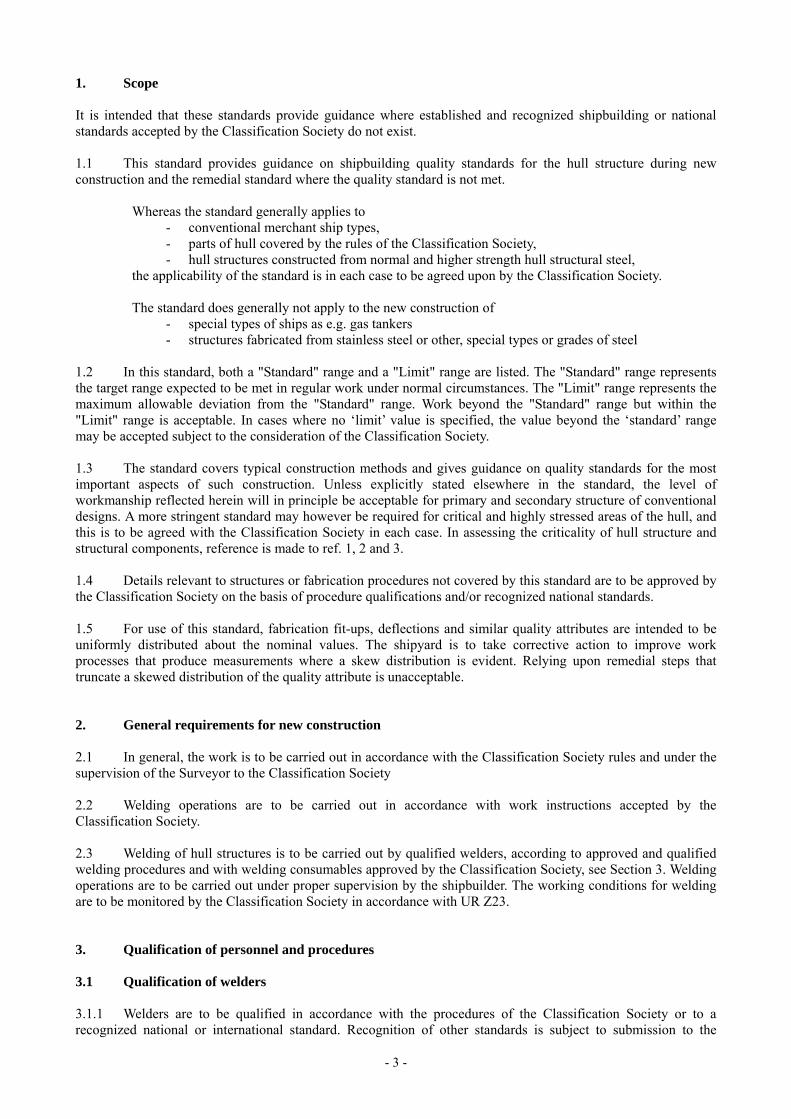
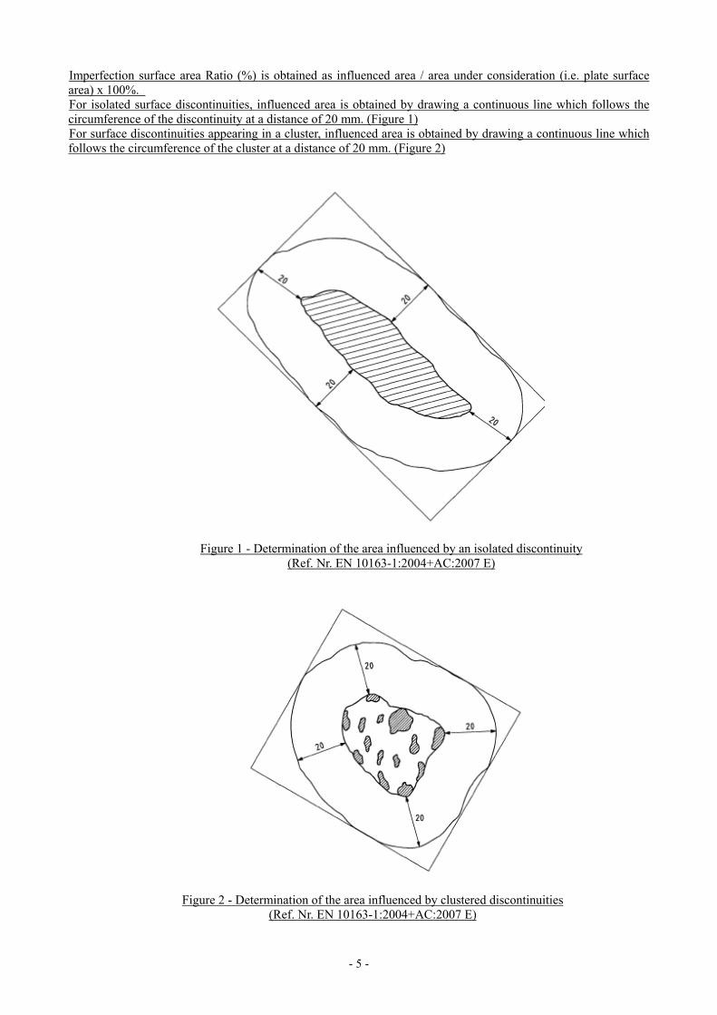
Imperfection surface area Ratio (%) is obtained as influenced area / area under consideration (i.e. plate surface area) x 100%. For isolated surface discontinuities, influenced area is obtained by drawing a continuous line which follows the circumference of the discontinuity at a distance of 20 mm. (Figure 1) For surface discontinuities appearing in a cluster, influenced area is obtained by drawing a continuous line which follows the circumference of the cluster at a distance of 20 mm. (Figure 2)
Figure 2 - Determination of the area influenced by clustered discontinuities (Ref. Nr. EN 10163-1:2004+AC:2007 E)
Figure 1 - Determination of the area influenced by an isolated discontinuity (Ref. Nr. EN 10163-1:2004+AC:2007 E)
- 6 -
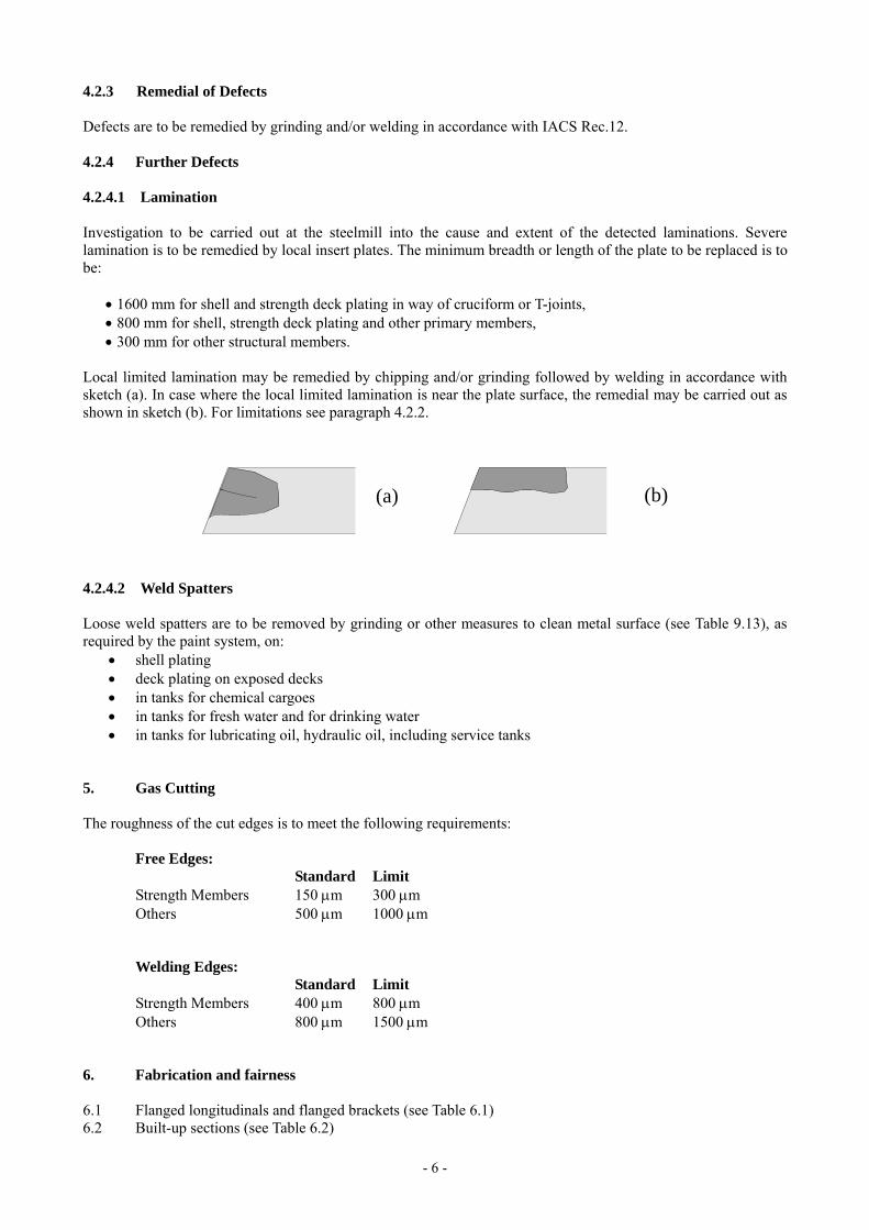
4.2.3 Remedial of Defects Defects are to be remedied by grinding and/or welding in accordance with IACS Rec.12. 4.2.4 Further Defects 4.2.4.1 Lamination Investigation to be carried out at the steelmill into the cause and extent of the detected laminations. Severe lamination is to be remedied by local insert plates. The minimum breadth or length of the plate to be replaced is to be:
• 1600 mm for shell and strength deck plating in way of cruciform or T-joints, • 800 mm for shell, strength deck plating and other primary members, • 300 mm for other structural members. Local limited lamination may be remedied by chipping and/or grinding followed by welding in accordance with sketch (a). In case where the local limited lamination is near the plate surface, the remedial may be carried out as shown in sketch (b). For limitations see paragraph 4.2.2.
(a) (b)
4.2.4.2 Weld Spatters Loose weld spatters are to be removed by grinding or other measures to clean metal surface (see Table 9.13), as required by the paint system, on:
• shell plating • deck plating on exposed decks • in tanks for chemical cargoes • in tanks for fresh water and for drinking water • in tanks for lubricating oil, hydraulic oil, including service tanks
5. Gas Cutting The roughness of the cut edges is to meet the following requirements:
Free Edges:
Standard Limit Strength Members 150 µm 300 µm Others 500 µm 1000 µm Welding Edges:
Standard Limit Strength Members 400 µm 800 µm Others 800 µm 1500 µm
6. Fabrication and fairness 6.1 Flanged longitudinals and flanged brackets (see Table 6.1) 6.2 Built-up sections (see Table 6.2)
- 7 -
6.3 Corrugated bulkheads (see Table 6.3) 6.4 Pillars, brackets and stiffeners (see Table 6.4) 6.5 Maximum heating temperature on surface for line heating (see Table 6.5) 6.6 Block assembly (see Table 6.6) 6.7 Special sub-assembly (see Table 6.7) 6.8 Shape (see Table 6.8 and 6.9) 6.9 Fairness of plating between frames (see Table 6.10) 6.10 Fairness of plating with frames (see Table 6.11) 6.11 Preheating for welding hull steels at low temperature (See Table 6.12) 7. Alignment The quality standards for alignment of hull structural components during new construction are shown in Tables 7.1, 7.2 and 7.3. The Classification Society may require a closer construction tolerance in areas requiring special attention, as follows:
• Regions exposed to high stress concentrations • Fatigue prone areas • Detail design block erection joints • High tensile steel regions
8. Welding Joint Details Edge preparation is to be qualified in accordance with URW28 or other recognized standard accepted by the Classification Society. Some typical edge preparations are shown in Table 8.1, 8.2, 8.3, 8.4 and 8.6 for reference. 8.1 Typical butt weld plate edge preparation (manual and semi-automatic welding) for reference - see Table
8.1 and 8.2 8.2 Typical fillet weld plate edge preparation (manual and semi-automatic welding) for reference - see Table
8.3 and 8.4 8.3 Butt and fillet weld profile (manual and semi-automatic welding) - see Table 8.5 8.4 Typical butt weld plate edge preparation (Automatic welding) for reference - see Table 8.6 8.5 Distance between welds - see Table 8.7 9. Remedial All the major remedial work is subject to reporting by shipbuilder to the Classification Society for approval in accordance with their work instruction for new building. Some typical remedial works are shown in Tables 9.1 to 9.13. 9.1 Typical misalignment remedial - see Tables 9.1 to 9.3 9.2 Typical butt weld plate edge preparation remedial (manual and semi-automatic welding) - see Table 9.4
and 9.5 9.3 Typical fillet weld plate edge preparation remedial (manual and semi-automatic welding) - see Tables 9.6
to 9.8 9.4 Typical fillet and butt weld profile remedial (manual and semi-automatic welding) - see Table 9.9 9.5 Distance between welds remedial - see Table 9.10 9.6 Erroneous hole remedial - see Table 9.11 9.7 Remedial by insert plate - see Table 9.12 9.8 Weld surface remedial - see Table 9.13 9.9 Weld remedial (short bead) - see Table 9.14
- 8 -
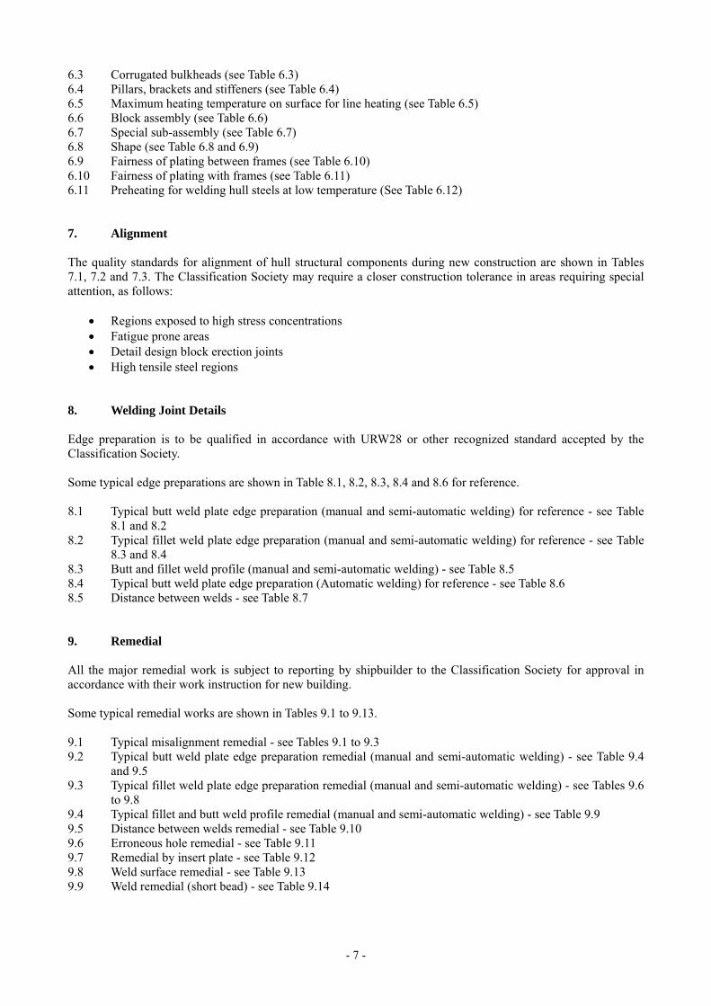
TABLE 6.1 – Flanged Longitudinals and Flanged Brackets
Detail Standard Limit Remarks
Breadth of flange
compared to correct size
± 3 mm ± 5 mm
Angle between flange and web
compared to template
± 3 mm ± 5 mm per 100 mm of a
Straightness in plane of flange and web
± 10 mm ± 25 mm per 10 m
- 9 -
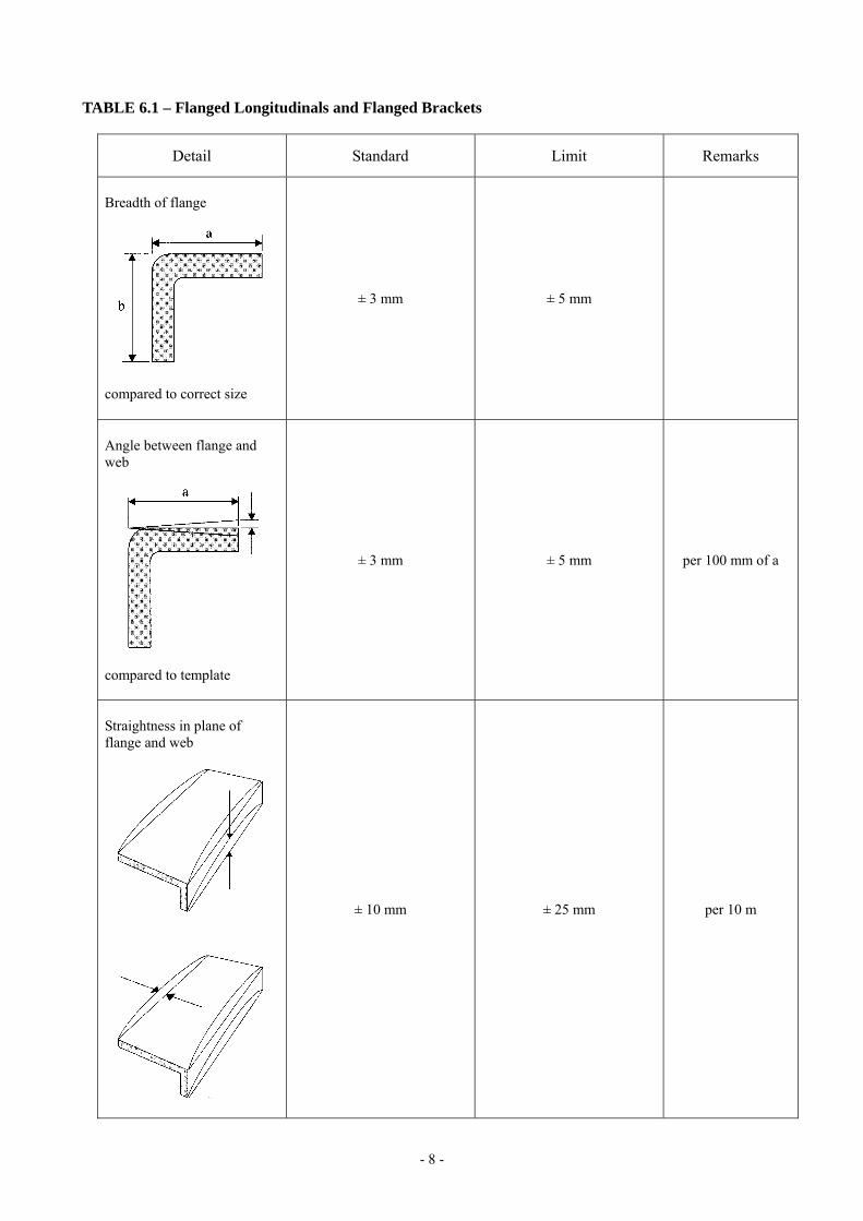
TABLE 6.2 – Built Up Sections
Detail Standard Limit Remarks Frames and longitudinal
± 1.5 mm ± 3 mm per 100 mm of a
Distortion of face plate
d ≤ 3 + a/100 mm d ≤ 5 + a/100 mm
Distortion in plane of web and flange of built up longitudinal frame, transverse frame, girder and transverse web.
± 10 mm
± 25 mm
per 10 m in length

- 10 -
TABLE 6.3 – Corrugated Bulkheads
Detail Standard Limit Remarks
Mechanical bending
R ≥ 3t mm 2t mm
Material to be suitable for cold flanging (forming) and welding in way of radius
Depth of corrugation
± 3 mm ± 6 mm
Breadth of corrugation
± 3 mm ± 6 mm
Pitch and depth of swedged corrugated bulkhead compared with correct value
h : ± 2.5 mm
Where it is not aligned with other bulkheads
P : ± 6 mm
Where it is aligned with other bulkheads
P : ± 2 mm
h : ± 5 mm
Where it is not aligned with other bulkheads
P : ± 9 mm
Where it is aligned with other bulkheads
P : ± 3 mm

- 11 -
TABLE 6.4 – Pillars, Brackets and Stiffeners
Detail Standard Limit Remarks
Pillar (between decks)
4 mm 6 mm
Cylindrical structure diameter (pillars, masts, posts, etc.)
± D/200 mm
max. + 5 mm
± D/150 mm
max. 7.5 mm
Tripping bracket and small stiffener, distortion at the part of free edge
a ≤ t/2 mm
t
Ovality of cylindrical structure
dmax – dmin ≤ 0.02 × dmax
dmin
d max
- 12 -
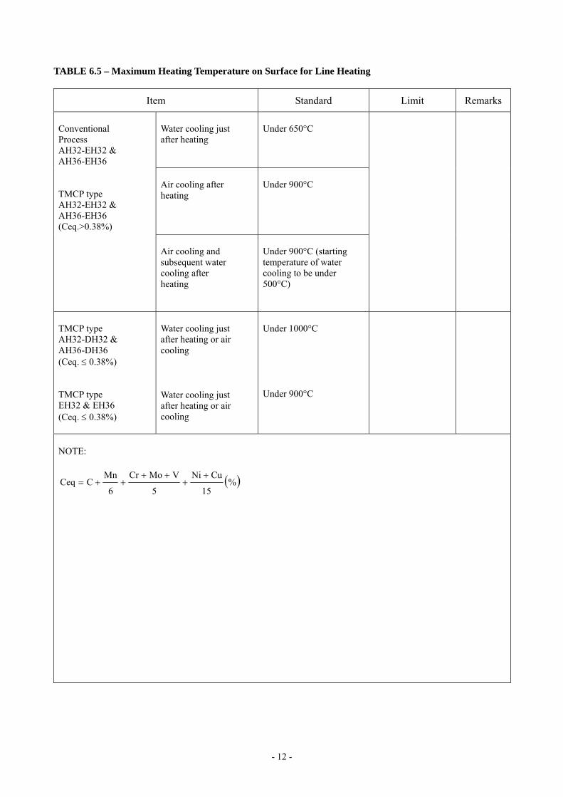
TABLE 6.5 – Maximum Heating Temperature on Surface for Line Heating
Item Standard Limit Remarks Water cooling just after heating
Under 650°C
Air cooling after heating
Under 900°C
Conventional Process AH32-EH32 & AH36-EH36 TMCP type AH32-EH32 & AH36-EH36 (Ceq.>0.38%)
Air cooling and subsequent water cooling after heating
Under 900°C (starting temperature of water cooling to be under 500°C)
TMCP type AH32-DH32 & AH36-DH36 (Ceq. ≤ 0.38%) TMCP type EH32 & EH36 (Ceq. ≤ 0.38%)
Water cooling just after heating or air cooling Water cooling just after heating or air cooling
Under 1000°C Under 900°C
NOTE:
( )%15
CuNi
5
VMoCr
6
MnCCeq
++
++++=

- 13 -
TABLE 6.6 – Block Assembly
Item Standard Limit Remarks
Flat Plate Assembly Length and Breadth Distortion Squareness Deviation of interior members from plate
± 4 mm
± 10 mm
± 5 mm
5 mm
± 6 mm
±20mm
±10mm
10mm
Curved plate assembly Length and Breadth Distortion Squareness Deviation of interior members from plate
± 4 mm
± 10 mm
± 10 mm
5 mm
± 8 mm
± 20 mm
± 15 mm
10 mm
measured along the girth
Flat cubic assembly Length and Breadth Distortion Squareness Deviation of interior members from plate Twist Deviation between upper and lower plate
± 4 mm
± 10 mm
± 5 mm
5 mm
± 10 mm
± 5 mm
± 6 mm
± 20 mm
± 10 mm
10 mm
± 20 mm
± 10 mm
Curved cubic assembly Length and Breadth Distortion Squareness Deviation of interior members from plate Twist Deviation between upper and lower plate
± 4 mm
± 10 mm
± 10 mm
± 5 mm
± 15 mm
± 7 mm
± 8 mm
± 20 mm
± 15 mm
± 10 mm
± 25 mm
± 15 mm
measured along with girth

- 14 -
TABLE 6.7 – Special Sub-Assembly
Item Standard Limit Remarks
Distance between upper/lower gudgeon
± 5 mm
± 10 mm
Distance between aft edge of boss and aft peak bulkhead
± 5 mm
± 10 mm
Twist of sub-assembly of stern frame
5 mm
10 mm
Deviation of rudder from shaft center line
4 mm
8 mm
Twist of rudder plate 6 mm
10 mm
Flatness of top plate of main engine bed
5 mm
10 mm
Breadth and length of top plate of main engine bed
± 4 mm
± 6 mm
NOTE: Dimensions and tolerances have to fulfill engine and equipment manufacturers’ requirements, if any.

- 15 -
TABLE 6.8 – Shape
Detail Standard Limit Remarks
Deformation for the whole length
± 50 mm per 100 m against the line of keel sighting
Deformation for the distance between two adjacent bulkheads
± 15 mm
Cocking-up of fore body
± 30 mm The deviation is to be measured from
the design line.
Cocking-up of aft-body
± 20 mm
Rise of floor amidships
± 15 mm The deviation is to be measured from
the design line.
- 16 -
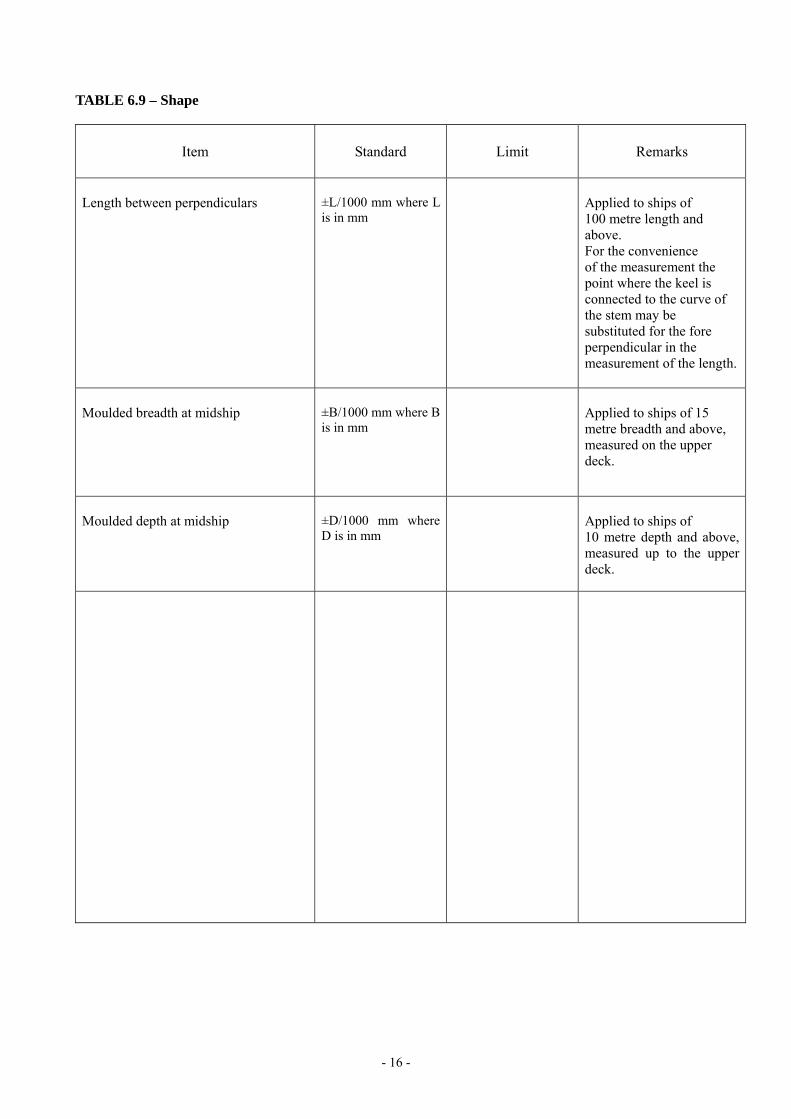
TABLE 6.9 – Shape
Item Standard Limit Remarks
Length between perpendiculars
±L/1000 mm where L is in mm
Applied to ships of 100 metre length and above. For the convenience of the measurement the point where the keel is connected to the curve of the stem may be substituted for the fore perpendicular in the measurement of the length.
Moulded breadth at midship
±B/1000 mm where B is in mm
Applied to ships of 15 metre breadth and above, measured on the upper deck.
Moulded depth at midship
±D/1000 mm where D is in mm
Applied to ships of 10 metre depth and above, measured up to the upper deck.

- 17 -
TABLE 6.10 – Fairness of Plating Between Frames
Item Standard Limit Remarks
Parallel part (side & bottom shell)
4 mm
Shell plate
Fore and aft part
5 mm
Tank top plate
4 mm
Bulkhead
Longl. Bulkhead Trans. Bulkhead Swash Bulkhead
6 mm
8 mm
Parallel part 4 mm 8 mm Strength deck
Fore and aft part Covered part
6 mm
7 mm
9 mm
9 mm
Bare part 6 mm 8 mm Second deck
Covered part 7 mm 9 mm
Bare part 4 mm 8 mm Forecastle deck poop deck
Covered part 6 mm 9 mm
Bare part 4 mm 6 mm Super structure deck
Covered part 7 mm 9 mm
Outside wall 4 mm 6 mm
Inside wall 6 mm 8 mm
House wall
Covered part 7 mm 9 mm
Interior member (web of girder, etc) 5 mm 7 mm
Floor and girder in double bottom 5 mm 8 mm

- 18 -
TABLE 6.11 – Fairness of Plating with Frames
Item Standard Limit Remarks
Parallel part ±2 l /1000 mm ±3 l /1000 mm Shell plate
Fore and aft part ±3 l /1000 mm ±4 l /1000 mm
Strength deck (excluding cross deck) and top plate of double bottom
-
±3 l /1000 mm
±4 l /1000 mm
Bulkhead
-
±5 l /1000 mm
l = span of frame (mm) To be measured between on trans. space (min. l = 3000 mm)
Accommodation above the strength deck and others
-
±5 l /1000 mm
±6 l /1000 mm
l = span of frame
(minimum l = 3000 mm)
To be measured between one trans. space.
mm

- 19 -
TABLE 6.12 – Preheating for welding hull steels at low temperature
Standard Limit Remarks
Item Base metal
temperature needed preheating
Minimum preheating
temperature
Normal strength steels A, B, D, E Below -5 oC
Higher strength steels
(TMCP type) Below 0 oC
Higher strength steels
(Conventional type)
AH32 – EH32 AH36 – EH36
Below 0 oC
20 oC 1)
(Note)
1) This level of preheat is to be applied unless the approved welding procedure specifies a higher level.

- 20 -
TABLE 7.1 – Alignment
Detail Standard Limit Remarks
Alignment of butt welds
a ≤ 0.15t strength member
a ≤ 0.2t other but maximum 4.0 mm
t is the lesser plate thickness
Alignment of fillet welds
t1 < t2
Strength member and higher stress member:
a ≤ t1/3 Other:
a ≤ t1/2
Alternatively, heel line can be used to check the alignment. Where t3 is less than t1, then t3 should be substituted for t1 in the standard.
Alignment of fillet welds
Strength member and higher stress member:
a ≤ t1/3 Other:
a ≤ t1/2
Alternatively, heel line can be used to check the alignment. Where t3 is less than t1, then t3 should be substitute for t1 in the standard.
t3/2 t3/2
t2 t2/2 t2/2
t1/2 t1/2
t2/2
t2/2
t1/2 t1/2
t3

- 21 -
TABLE 7.2 – Alignment
Detail Standard Limit Remarks
Alignment of flange of T-longitudinal
b (mm)
Strength member a ≤ 0.04b (mm) a = 8.0 mm
Alignment of height of T-bar, L-angle bar or bulb
Strength member a ≤ 0.15t Other a ≤ 0.20t
a = 3.0 mm
Alignment of panel stiffener
d ≤ L/50
Gap between bracket/intercostal and stiffener
a ≤ 2.0 mm a = 3.0 mm
Alignment of lap welds
a ≤ 2.0 mm a = 3.0 mm
- 22 -
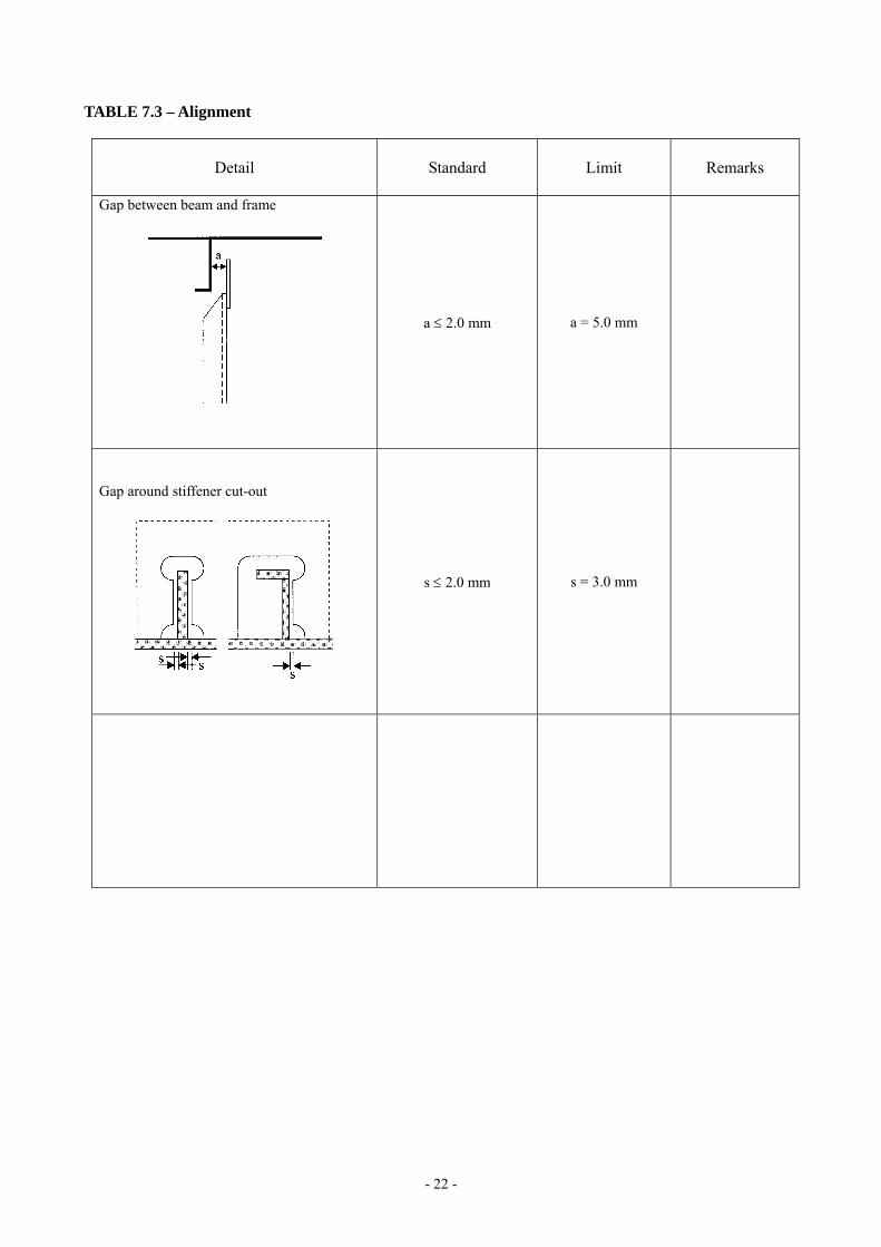
TABLE 7.3 – Alignment
Detail Standard Limit Remarks
Gap between beam and frame
a ≤ 2.0 mm a = 5.0 mm
Gap around stiffener cut-out
s ≤ 2.0 mm s = 3.0 mm
- 23 -
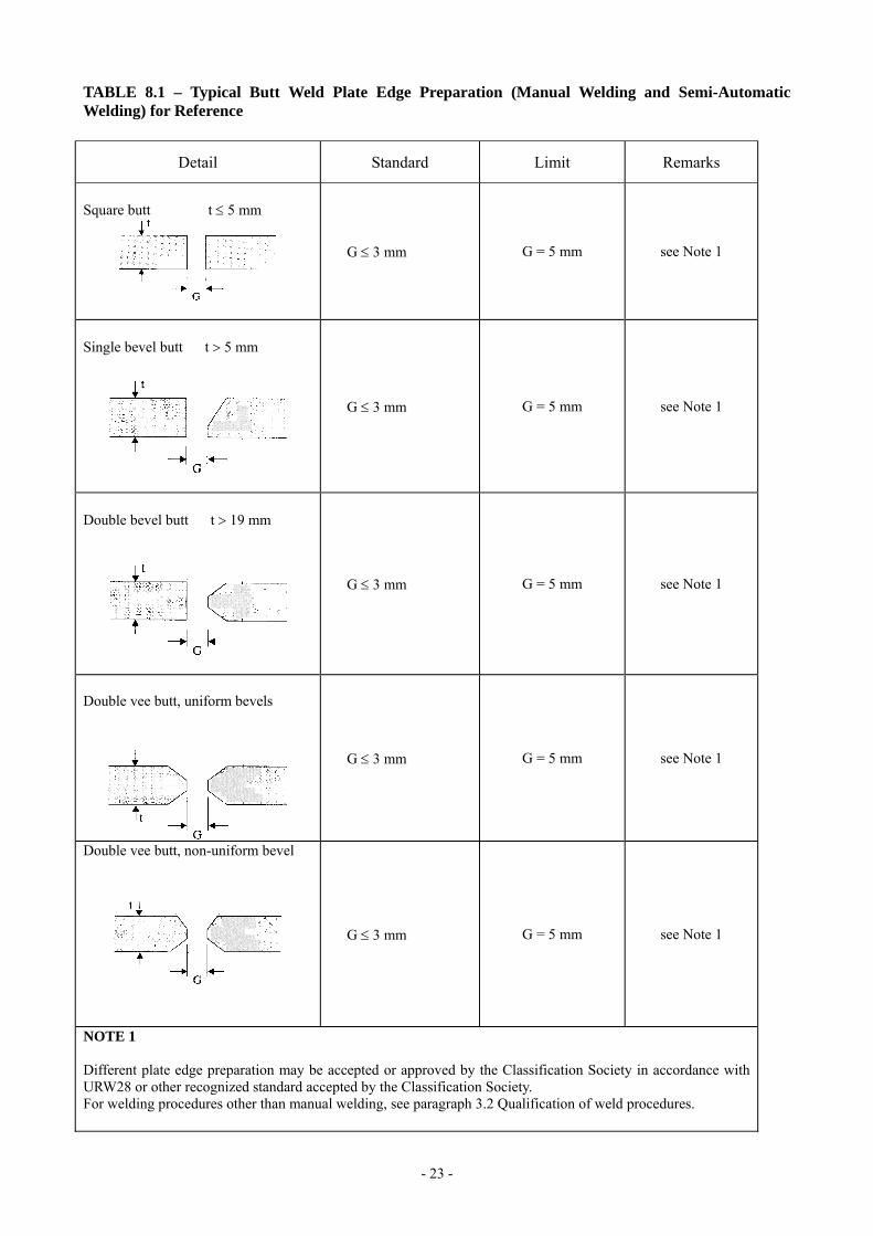
TABLE 8.1 – Typical Butt Weld Plate Edge Preparation (Manual Welding and Semi-Automatic Welding) for Reference
Detail Standard Limit Remarks
Square butt t ≤ 5 mm
G ≤ 3 mm G = 5 mm see Note 1
Single bevel butt t > 5 mm
G ≤ 3 mm
G = 5 mm see Note 1
Double bevel butt t > 19 mm
G ≤ 3 mm
G = 5 mm see Note 1
Double vee butt, uniform bevels
G ≤ 3 mm
G = 5 mm see Note 1
Double vee butt, non-uniform bevel
G ≤ 3 mm
G = 5 mm see Note 1
NOTE 1 Different plate edge preparation may be accepted or approved by the Classification Society in accordance with URW28 or other recognized standard accepted by the Classification Society. For welding procedures other than manual welding, see paragraph 3.2 Qualification of weld procedures.

- 24 -
TABLE 8.2 – Typical Butt Weld Plate Edge Preparation (Manual Welding and Semi-Automatic Welding) for Reference
Detail Standard Limit Remarks
Single Vee butt, one side welding with backing strip (temporary or permanent)
G = 3 to 9 mm
G = 16 mm see Note 1
Single vee butt
G ≤ 3 mm
G = 5 mm see Note 1
NOTE 1 Different plate edge preparation may be accepted or approved by the Classification Society in accordance with URW28 or other recognized standard accepted by the Classification Society. For welding procedures other than manual welding, see paragraph 3.2 Qualification of welding procedures.

- 25 -
Table 8.3 – Typical Fillet Weld Plate Edge Preparation (Manual Welding and Semi-Automatic Welding) for Reference
Detail Standard Limit Remarks
Tee Fillet
G ≤ 2 mm G = 3 mm see Note 1
Inclined fillet
G ≤ 2 mm G = 3 mm see Note 1
Single bevel tee with permanent backing
G ≤ 4 to 6 mm θ° = 30° to 45°
G = 16 mm
Not normally for strength member
also see Note 1
Single bevel tee
G ≤ 3 mm
see Note 1
NOTE 1 Different plate edge preparation may be accepted or approved by the Classification Society in accordance with URW28 or other recognized standard accepted by the Classification Society. For welding procedures other than manual welding, see paragraph 3.2 Qualification of welding procedures.
- 26 -
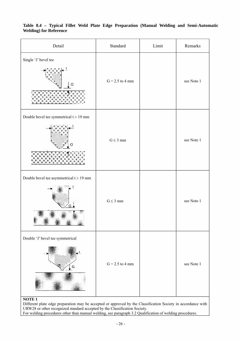
Table 8.4 – Typical Fillet Weld Plate Edge Preparation (Manual Welding and Semi-Automatic Welding) for Reference
Detail Standard Limit Remarks
Single ‘J’ bevel tee
G = 2.5 to 4 mm
see Note 1
Double bevel tee symmetrical t > 19 mm
G ≤ 3 mm
see Note 1
Double bevel tee asymmetrical t > 19 mm
G ≤ 3 mm
see Note 1
Double ‘J’ bevel tee symmetrical
G = 2.5 to 4 mm
see Note 1
NOTE 1 Different plate edge preparation may be accepted or approved by the Classification Society in accordance with URW28 or other recognized standard accepted by the Classification Society. For welding procedures other than manual welding, see paragraph 3.2 Qualification of welding procedures.
- 27 -
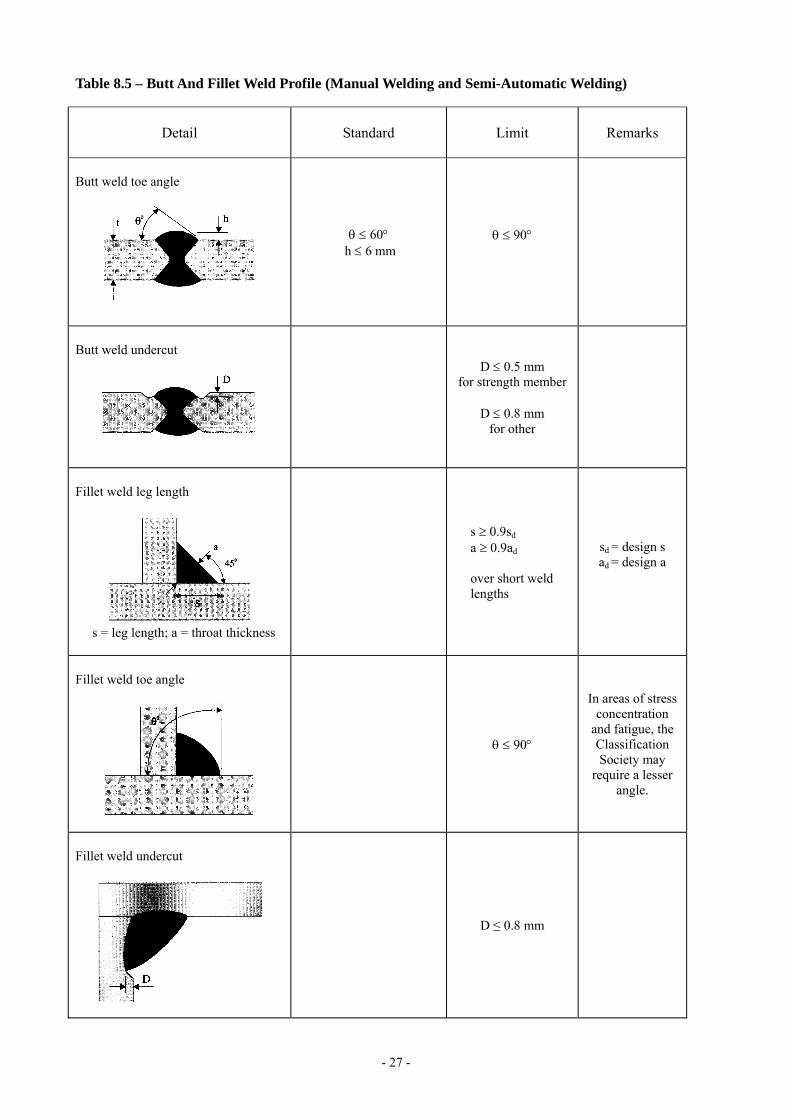
Table 8.5 – Butt And Fillet Weld Profile (Manual Welding and Semi-Automatic Welding)
Detail Standard Limit Remarks
Butt weld toe angle
θ ≤ 60° h ≤ 6 mm
θ ≤ 90°
Butt weld undercut
D ≤ 0.5 mm for strength member
D ≤ 0.8 mm
for other
Fillet weld leg length
s = leg length; a = throat thickness
s ≥ 0.9sd
a ≥ 0.9ad over short weld lengths
sd = design s ad = design a
Fillet weld toe angle
θ ≤ 90°
In areas of stress concentration
and fatigue, the Classification Society may
require a lesser angle.
Fillet weld undercut
D ≤ 0.8 mm
- 28 -
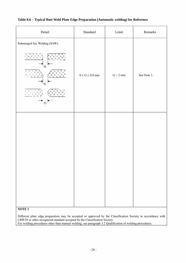
Table 8.6 – Typical Butt Weld Plate Edge Preparation (Automatic welding) for Reference
Detail Standard Limit Remarks
Submerged Arc Welding (SAW)
0 ≤ G ≤ 0.8 mm
G = 2 mm
See Note 1.
NOTE 1 Different plate edge preparation may be accepted or approved by the Classification Society in accordance with URW28 or other recognized standard accepted by the Classification Society. For welding procedures other than manual welding, see paragraph 3.2 Qualification of welding procedures.

- 29 -
Table 8.7 – Distance Between Welds
Detail Standard Limit Remarks
Scallops over weld seams
r
d
for strength member d ≥ 5mm
for other d ≥ 0mm
The “d” is to be measured from the toe of the fillet weld to the toe of the butt weld.
Distance between two butt welds
d ≥ 0 mm
Distance between butt weld and fillet weld
for strength
member d ≥ 10 mm
for other d ≥ 0 mm
The “d” is to be measured from the toe of the fillet weld to the toe of the butt weld.
for cut-outs d ≥ 30 mm
Distance between butt welds
for margin plates d ≥ 300 mm
150 mm

- 30 -
Table 9.1 – Typical Misalignment Remedial
Detail Remedial Standard Remarks
Alignment of butt joints
Strength member a > 0.15t1 or a > 4 mm release and adjust Other a > 0.2t1 or a > 4 mm release and adjust
t1 is lesser plate thickness
Alignment of fillet welds
Strength member and higher stress member t1/3 < a ≤ t1/2 - generally increase weld throat by 10% a > t1/2 - release and adjust over a minimum of 50a Other a > t1/2 - release and adjust over a minimum of 30a
Alternatively, heel line can be used to check the alignment. Where t3 is less than t1 then t3 should be substituted for t1 in standard
Alignment of flange of T-longitudinal
When 0.04b < a ≤ 0.08b, max 8 mm: grind corners to smooth taper over a minimum distance L = 3a When a > 0.08b or 8 mm: grind corners to smooth taper over a minimum distance L = 50a
Alignment of height of T-bar, L-angle bar or bulb
When 3 mm < a ≤ 6 mm: build up by welding When a > 6 mm: release and adjust over minimum L = 50a for strength member and L = 30a for other
Alignment of lap welds
3 mm < a ≤ 5 mm: weld leg length to be increased by the same amount as increase in gap in excess of 3 mm a > 5 mm: members to be re-aligned
t1
a1
t2/2
t2/2
t1/2 t1/2
- 31 -
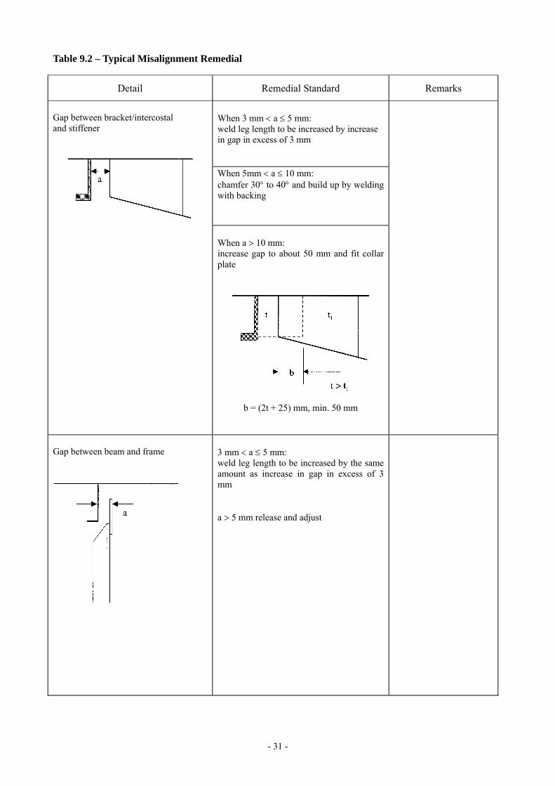
Table 9.2 – Typical Misalignment Remedial
Detail Remedial Standard Remarks
When 3 mm < a ≤ 5 mm: weld leg length to be increased by increase in gap in excess of 3 mm
When 5mm < a ≤ 10 mm: chamfer 30° to 40° and build up by welding with backing
Gap between bracket/intercostal and stiffener
When a > 10 mm: increase gap to about 50 mm and fit collar plate
b = (2t + 25) mm, min. 50 mm
Gap between beam and frame
3 mm < a ≤ 5 mm: weld leg length to be increased by the same amount as increase in gap in excess of 3 mm a > 5 mm release and adjust
- 32 -
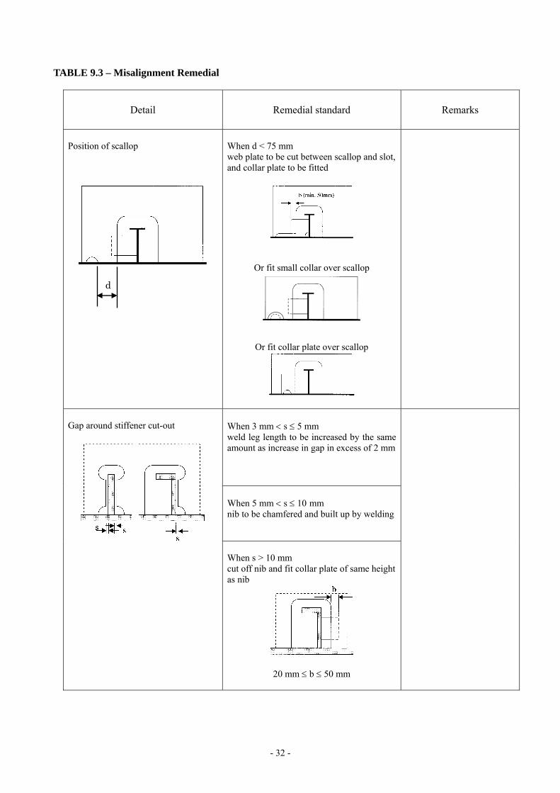
TABLE 9.3 – Misalignment Remedial
Detail Remedial standard Remarks
Position of scallop
When d < 75 mm web plate to be cut between scallop and slot, and collar plate to be fitted
Or fit small collar over scallop
Or fit collar plate over scallop
When 3 mm < s ≤ 5 mm weld leg length to be increased by the same amount as increase in gap in excess of 2 mm When 5 mm < s ≤ 10 mm nib to be chamfered and built up by welding
Gap around stiffener cut-out
When s > 10 mm cut off nib and fit collar plate of same height as nib
20 mm ≤ b ≤ 50 mm
d
- 33 -
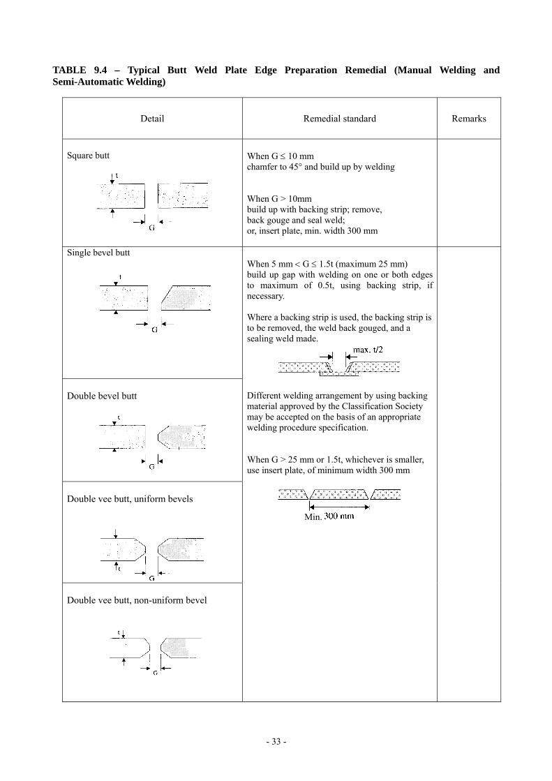
TABLE 9.4 – Typical Butt Weld Plate Edge Preparation Remedial (Manual Welding and Semi-Automatic Welding)
Detail Remedial standard Remarks
Square butt
When G ≤ 10 mm chamfer to 45° and build up by welding When G > 10mm build up with backing strip; remove, back gouge and seal weld; or, insert plate, min. width 300 mm
Single bevel butt
Double bevel butt
Double vee butt, uniform bevels
Double vee butt, non-uniform bevel
When 5 mm < G ≤ 1.5t (maximum 25 mm) build up gap with welding on one or both edges to maximum of 0.5t, using backing strip, if necessary. Where a backing strip is used, the backing strip is to be removed, the weld back gouged, and a sealing weld made.
Different welding arrangement by using backing material approved by the Classification Society may be accepted on the basis of an appropriate welding procedure specification. When G > 25 mm or 1.5t, whichever is smaller, use insert plate, of minimum width 300 mm
Min.

- 34 -
TABLE 9.5 – Typical Butt Weld Plate Edge Preparation Remedial (Manual Welding and Semi-Automatic Welding)
Detail Remedial Standard Remarks
Single vee butt, one side welding
Single vee butt
When 5 mm < G ≤ 1.5t mm (maximum 25 mm), build up gap with welding on one or both edges, to maximum of 0.5t, using backing strip, if necessary. “Limit” gap size preferably to “Standard” gap size as described in Table 8.2. Where a backing strip is used, the backing strip is to be removed, the weld back gouged, and a sealing weld made. Different welding arrangement by using backing material approved by the Classification Society may be accepted on the basis of an appropriate welding procedure specification.
When G > 25 mm or 1.5t, whichever is smaller, use insert plate of minimum width 300 mm.
Min.
max. t/2 Limits see Table 8.2
- 35 -
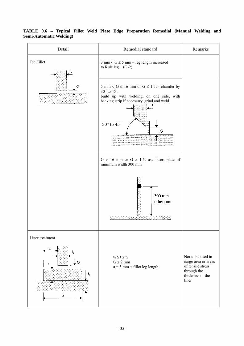
TABLE 9.6 – Typical Fillet Weld Plate Edge Preparation Remedial (Manual Welding and Semi-Automatic Welding)
Detail Remedial standard Remarks
3 mm < G ≤ 5 mm – leg length increased to Rule leg + (G-2)
5 mm < G ≤ 16 mm or G ≤ 1.5t - chamfer by 30° to 45°, build up with welding, on one side, with backing strip if necessary, grind and weld.
Tee Fillet
G > 16 mm or G > 1.5t use insert plate of minimum width 300 mm
Liner treatment
t2 ≤ t ≤ t1 G ≤ 2 mm a = 5 mm + fillet leg length
Not to be used in cargo area or areas of tensile stress through the thickness of the liner
30° to 45°
- 36 -
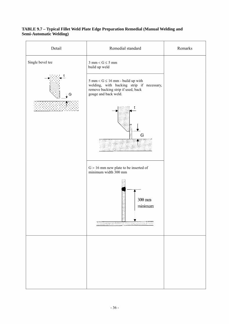
TABLE 9.7 – Typical Fillet Weld Plate Edge Preparation Remedial (Manual Welding and Semi-Automatic Welding)
Detail Remedial standard Remarks
3 mm < G ≤ 5 mm build up weld
5 mm < G ≤ 16 mm - build up with welding, with backing strip if necessary, remove backing strip if used, back gouge and back weld.
Single bevel tee
G > 16 mm new plate to be inserted of minimum width 300 mm

- 37 -
TABLE 9.8 – Typical Fillet Weld Plate Edge Preparation Remedial (Manual Welding and Semi-Automatic Welding)
Detail Remedial standard Remarks
Single ‘J’ bevel tee
as single bevel tee
Double bevel tee symmetrical
Double bevel tee asymmetrical
Double ‘J’ bevel symmetrical
When 5 mm < G ≤ 16 mm build up with welding using ceramic or other approved backing bar, remove, back gouge and back weld.
When G > 16 mm-insert plate of minimum height 300 mm to be fitted.
- 38 -
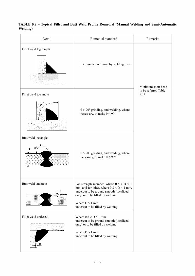
TABLE 9.9 – Typical Fillet and Butt Weld Profile Remedial (Manual Welding and Semi-Automatic Welding)
Detail Remedial standard Remarks
Fillet weld leg length
Increase leg or throat by welding over
Fillet weld toe angle
θ > 90° grinding, and welding, where necessary, to make θ ≤ 90°
Butt weld toe angle
θ > 90° grinding, and welding, where necessary, to make θ ≤ 90°
Butt weld undercut
For strength member, where 0.5 < D ≤ 1 mm, and for other, where 0.8 < D ≤ 1 mm, undercut to be ground smooth (localized only) or to be filled by welding Where D > 1 mm undercut to be filled by welding
Fillet weld undercut
Where 0.8 < D ≤ 1 mm undercut to be ground smooth (localized only) or to be filled by welding Where D > 1 mm undercut to be filled by welding
Minimum short bead to be referred Table 9.14
- 39 -
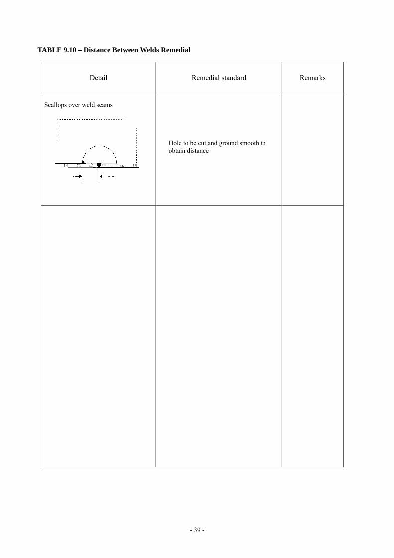
TABLE 9.10 – Distance Between Welds Remedial
Detail Remedial standard Remarks
Scallops over weld seams
Hole to be cut and ground smooth to obtain distance

- 40 -
TABLE 9.11 – Erroneous Hole Remedial
Detail Remedial standard Remarks
Strength member open hole to minimum 75 mm dia., fit and weld spigot piece Or open hole to over 300 mm and fit insert plate
Holes made erroneously D < 200 mm
Other open hole to over 300 mm and fit insert plate Or fit lap plate
t1 = t2 L = 50 mm, min
Fillet weld to be made after butt weld The fitting of spigot pieces in areas of high stress concentration or fatigue is to be approved by the Classification Society.
Strength member open hole and fit insert plate
Holes made erroneously D ≥ 200 mm
Other open hole to over 300 mm and fit insert plate Or fit lap plate
t1 = t2 L = 50 mm, min
θ = 30 – 40° G = 4 – 6 mm 1/2t ≤ t1 ≤ t l = 50 mm
- 41 -
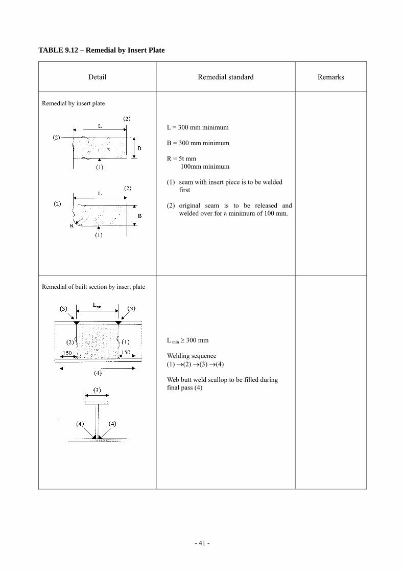
TABLE 9.12 – Remedial by Insert Plate
Detail Remedial standard Remarks
Remedial by insert plate
L = 300 mm minimum B = 300 mm minimum R = 5t mm 100mm minimum (1) seam with insert piece is to be welded
first (2) original seam is to be released and
welded over for a minimum of 100 mm.
Remedial of built section by insert plate
L min ≥ 300 mm Welding sequence (1) →(2) →(3) →(4) Web butt weld scallop to be filled during final pass (4)
- 42 -
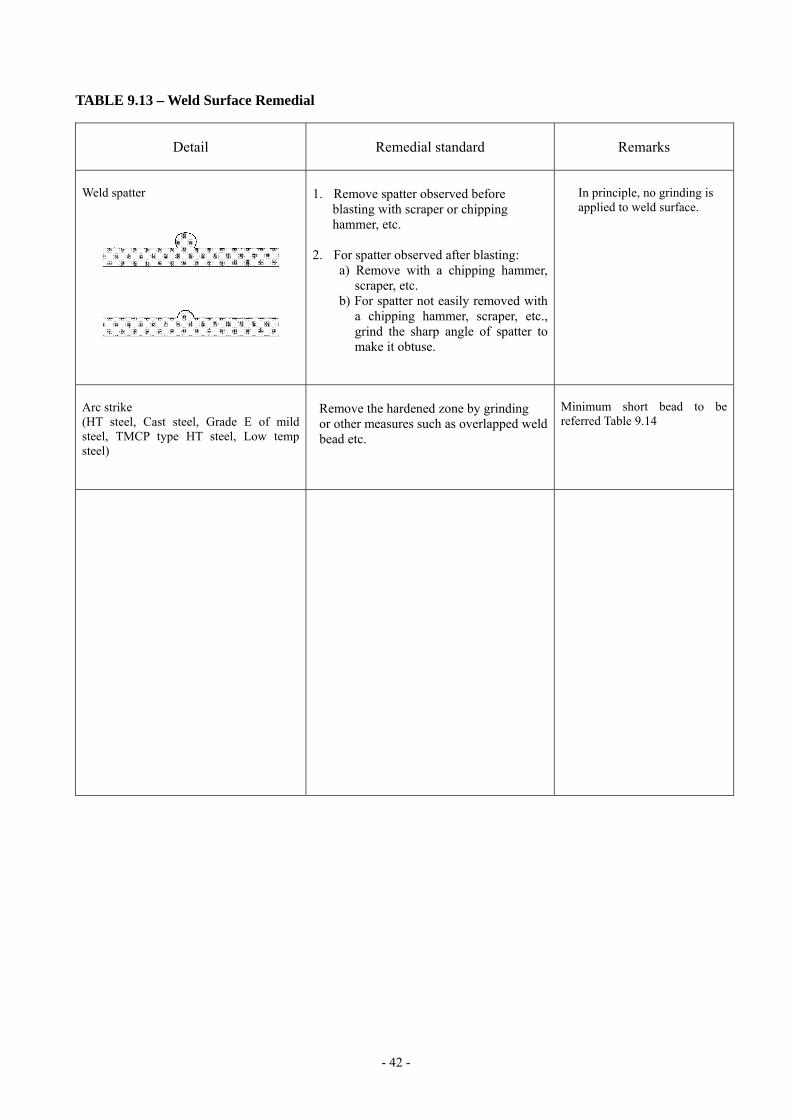
TABLE 9.13 – Weld Surface Remedial
Detail Remedial standard Remarks
Weld spatter
1. Remove spatter observed before blasting with scraper or chipping hammer, etc. 2. For spatter observed after blasting: a) Remove with a chipping hammer,
scraper, etc. b) For spatter not easily removed with
a chipping hammer, scraper, etc., grind the sharp angle of spatter to make it obtuse.
In principle, no grinding is applied to weld surface.
Arc strike (HT steel, Cast steel, Grade E of mild steel, TMCP type HT steel, Low temp steel)
Remove the hardened zone by grinding or other measures such as overlapped weld bead etc.
Minimum short bead to be referred Table 9.14
- 43 -
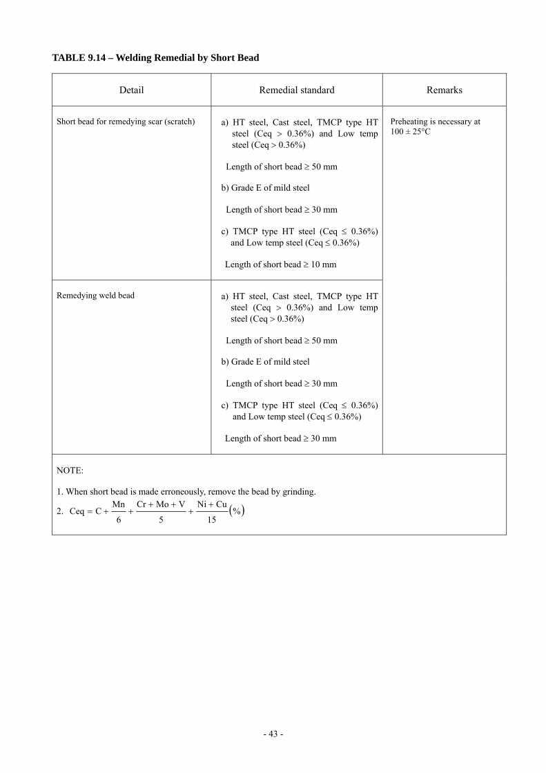
TABLE 9.14 – Welding Remedial by Short Bead
Detail Remedial standard Remarks
Short bead for remedying scar (scratch)
a) HT steel, Cast steel, TMCP type HT
steel (Ceq > 0.36%) and Low temp steel (Ceq > 0.36%)
Length of short bead ≥ 50 mm b) Grade E of mild steel Length of short bead ≥ 30 mm c) TMCP type HT steel (Ceq ≤ 0.36%)
and Low temp steel (Ceq ≤ 0.36%)
Length of short bead ≥ 10 mm
Remedying weld bead
a) HT steel, Cast steel, TMCP type HT
steel (Ceq > 0.36%) and Low temp steel (Ceq > 0.36%)
Length of short bead ≥ 50 mm b) Grade E of mild steel Length of short bead ≥ 30 mm c) TMCP type HT steel (Ceq ≤ 0.36%)
and Low temp steel (Ceq ≤ 0.36%)
Length of short bead ≥ 30 mm
Preheating is necessary at 100 ± 25°C
NOTE: 1. When short bead is made erroneously, remove the bead by grinding.
2. ( )%15
CuNi
5
VMoCr
6
MnCCeq
++
++++=