thesis NG FCAW of high strength shipbuilding steels .pdf
121
LAPPEENRANTA UNIVERSITY OF TECHNOLOGY Mechanical Engineering Laboratory of Welding technology Masters´s Thesis Juha-Pekka Keltanen NARROW GAP FLUX-CORED ARC WELDING OF HIGH STRENGTH SHIPBUILDING STEELS Examiners: Prof. Jukka Martikainen Lic.Sc. Matti Nallikari
-
Upload
khangminh22 -
Category
Documents
-
view
2 -
download
0
Transcript of thesis NG FCAW of high strength shipbuilding steels .pdf

LAPPEENRANTA UNIVERSITY OF TECHNOLOGY
Mechanical Engineering
Laboratory of Welding technology
Masters´s Thesis
Juha-Pekka Keltanen
NARROW GAP FLUX-CORED ARC WELDING OF HIGH STRENGTH
SHIPBUILDING STEELS
Examiners: Prof. Jukka Martikainen
Lic.Sc. Matti Nallikari

ABSTRACT
Lappeenranta University of Technology
Department of Mechanical Engineering
Juha-Pekka Keltanen
Narrow Gap flux-cored arc welding of high strength shipbuilding steels
Master’s thesis
2015
88 pages, 31 figures, 20 tables and 12 appendices.
Examiners: Prof. Jukka Martikainen
Lic.Sc. Matti Nallikari
Keywords: Arctic environment, shipbuilding, high strength steels, narrow gap welding,
FCAW, mechanization, Wise process
This thesis is part of the Arctic Materials Technologies Development –project. The
research of the thesis was done in cooperation with Arctech Helsinki Shipyard,
Lappeenranta University of Technology and Kemppi Oy. Focus of the thesis was to study
narrow gap flux-cored arc welding of two high strength steels with three different groove
angles of 20°, 10° and 5°. Welding of the 25 mm thick E500 TMCP and 10 mm thick
EH36 steels was mechanized and Kemppi WisePenetration and WiseFusion processes
were tested with E500 TMCP steel. EH36 steel test pieces were welded without Wise
processes. Shielding gases chosen were carbon dioxide and a mixture of argon and carbon
dioxide. Welds were tested with non-destructive and destructive testing methods.
Radiographic, visual, magnetic particle and liquid penetrant testing proved that welds were
free from imperfections. After non-destructive testing, welds were tested with various
destructive testing methods. Impact strength, bending, tensile strength and hardess tests
proved that mechanized welding and Wise processes produced quality welds with narrower
gap. More inconsistent results were achieved with test pieces welded without Wise
processes. Impact test results of E500 TMCP exceeded the 50 J limit on weld, set by
Russian Maritime Register of Shipping. EH36 impact test results were much closer to the
limiting values of 34 J on weld and 47 on HAZ. Hardness values of all test specimens were
below the limiting values. Bend testing and tensile testing results fulfilled the the Register
requirements. No cracking or failing occurred on bend test specimens and tensile test
results exceeded the Register limits of 610 MPa for E500 TMCP and 490 MPa for EH36.

TIIVISTELMÄ
Lappeenrannan teknillinen yliopisto
Konetekniikan koulutusohjelma
Juha-Pekka Keltanen
Lujien laivaterästen kapearailo MAG-taytelankahitsaus
Diplomityö
2015
88 sivua, 31 kuvaa, 20 taulukkoa, 12 liitettä
Tarkastajat: Prof. Jukka Martikainen
TkL Matti Nallikari
Avainsanat: Arktinen ympäristö, laivanrakennus, lujat teräkset, kapearailohitsaus,
FCAW, mekanisointi, Wise-prosessi
Tämä työ on osa Arctic Materials Technologies Development -projektia. Diplomityö
tehtiin yhteistyössä Arctech Helsingin telakan, Lappeenrannan teknillisen yliopiston ja
Kemppi Oy:n kanssa. Työn tavoitteena oli tutkia lujien terästen mekanisoitua MAG-
täytelankakapearailohitsausta. Kahdesta eri lujuusluokan ja paksuuden teräksistä hitsattiin
20, 10 ja 5 asteen railokulmilla koekappaleita. 25 mm paksun E500 TMCP ja 10 mm
paksun EH36 teräksen hitsaus oli mekanisoitua. Kemppi Oy:n kehittämiä WisePenetration
ja WiseFusion -prosesseja käytettiin E500 TMCP teräksen hitsauksessa, kun taas EH36
teräksen koekappaleet hitsattiin ilman Wise-prosesseja. Suojakaasuiksi valittiin
hiilidioksidi ja argonin sekä hiilidioksidin seoskaasu. Hitsejä tutkittiin sekä ainetta
rikkomattomilla että ainetta rikkovilla menetelmillä. Radiografinen, magneettijauhe-,
visuaalinen ja tunkeumanestetarkastus osoittivat, ettei hitseissä ollut hitsausvirheitä.
Ainetta rikkovat isku-, taivutus-, veto- ja kovuuskokeet osoittivat, että mekanisoitu
kapearailohitsaus yhdessä Wise-prosessien kanssa tuottaa laadukkaita hitsejä. Ilman Wise-
prosesseja hitsattujen koekappaleiden tuloksissa esiintyi enemmän vaihtelua. E500 TMCP
iskukoetulokset ylittivät Venäjän laivaliikenteen merirekisterin rajan 50 Joulea
hitsiaineessa. EH36 iskukoetulokset olivat Rekisterin asettamilla rajoilla, 34 Joulea
hitsiaineessa ja 47 Joulea HAZ:ssa. Hitsien kovuusarvot pysyivät alle vaatimusten, eikä
taivutuskoesauvoissa esiintynyt halkeamia. Myös vetokoetulokset ylittivät Rekisterin
vaatimukset, 610 MPa E500 TMCP teräksellä ja 490 MPa EH36 teräksellä.

Contents
1 INTRODUCTION ....................................................................................................... 12
1.1 Background of the thesis ...................................................................................... 12
1.2 Aim of the study .................................................................................................. 12
1.3 Arctech Helsinki Shipyard ................................................................................... 13
2 NARROW GAP FLUX-CORED ARC WELDING (FC-NGAW) ............................. 14
2.1 Flux-cored arc process ......................................................................................... 17
2.1.1 Kemppi Wise products ..................................................................................... 19
2.2 Welding positions & flux-cored wires ................................................................. 20
2.3 Groove shapes and gaps ....................................................................................... 21
2.4 Welding mechanization ....................................................................................... 24
2.5 Productivity and economy of FC-NGAW ........................................................... 25
3 HIGH STRENGTH STEELS USED IN SHIPBUILDING ......................................... 27
3.1 Properties requirements for steels ........................................................................ 28
3.1.1 Mechanical properties ...................................................................................... 28
3.1.2 Cold resistant ................................................................................................... 29
3.2 Rules, Standards and Classification ..................................................................... 29
4 WELDABILITY OF HIGH STRENGTH STEELS .................................................... 31
4.1 Chemical composition ......................................................................................... 32
4.2 Prosessing routes of high strength steels ............................................................. 33
4.3 Problems and benefits of high strentgh steels ...................................................... 35
4.4 Heat input and cooling rate .................................................................................. 36
4.5 Transition temperature & Brittle fracture ............................................................ 38
4.6 Weld imperfections and quality level .................................................................. 40
4.6.1 Hydrogen cracking ........................................................................................... 40

4.6.2 Hot cracking ..................................................................................................... 41
5 QUALITY ASSURANCE OF FC-NGAW ................................................................. 45
5.1 Quality factors ...................................................................................................... 47
5.2 Welding procedure test ........................................................................................ 48
5.3 Testing methods ................................................................................................... 49
5.3.1 Non-destructive testing .................................................................................... 50
5.3.2 Destructive testing ........................................................................................... 51
5.4 WPQR and WPS .................................................................................................. 53
5.5 Comparison of RMRS procedures of testing to EN ............................................ 54
6 EXPERIMENTAL TESTING ..................................................................................... 58
6.1 Experimental plan ................................................................................................ 58
6.2 Testing materials and welding tests ..................................................................... 59
6.2.1 Welding tests with E500 TM steel ................................................................... 61
6.2.2 Welding tests with EH36 steel ......................................................................... 61
6.3 Non-destructive and destructive testing ............................................................... 62
7 EQUIPMENT .............................................................................................................. 64
8 RESULTS AND DISCUSSION .................................................................................. 67
8.1 Non-destructive testing ........................................................................................ 67
8.2 Bend testing ......................................................................................................... 69
8.3 Impact testing ....................................................................................................... 69
8.4 Tensile testing ...................................................................................................... 71
8.5 Hardness and macro testing ................................................................................. 73
8.6 pWPS ................................................................................................................... 76
8.7 Conclusion and Discussion .................................................................................. 78
9 SUMMARY ................................................................................................................. 80
REFERENCES .................................................................................................................... 82

APPENDICES
Appendix 1: Mechanical properties of rolled steel products
Appendix 2: Minimal elongation values for standard specimens of full
thickness with design length of 200 mm
Appendix 3: Preliminary experimental plan for M21 shielding gas
Appendix 4: Preliminary experimental plan for CO2 shielding gas
Appendix 5: Test sertificate for E500 TM steel
Appendix 6: Test sertificate for EH36 steel
Appendix 7: Welding consumable test certificates
Appendix 8: Welding parameter records
Appendix 9: Bend testing records
Appendix 10: Impact test records
Appendix 11: Tensile test records
Appendix 12: Hardness test records

LIST OF FIGURES
Figure 1. Drydock and icebreaker "Baltika" (Arctech, 2014) ............................................. 13
Figure 2. The effect of joint preparation on weld cross-sectional area (Norrish, 2006, p.
166) ...................................................................................................................................... 14
Figure 3. Comparison of cross-sectional area (Cary & Helzer, 2005, p. 676)..................... 15
Figure 4. Weld bead placement (Norrish, 2006, p. 172) ..................................................... 16
Figure 5. The principle of flux-cored arc welding (Lepola & Makkonen, 2005, p. 138) .... 18
Figure 6. Comparison of standard 1-MIG-process and 1-MIG-process with
WisePenetration (Kemppi Oy, 2014, p. 8) ........................................................................... 20
Figure 7. Typical narrow gap joint preparations (Norrish, 2006, p. 167) ............................ 22
Figure 8. The effect of root gap to cross-sectional area ....................................................... 23
Figure 9. Comparison of current and new narrow groove joint preparation (Nykänen, 2014)
............................................................................................................................................. 23
Figure 10. The effect of cooling rate on the properties of HAZ (Ruukki, 2014a, p. 7) ....... 36
Figure 11. Energy absorption transition curve of low-alloyed steel (replotted from
Kobelco, 2008, p. 8) ............................................................................................................. 39
Figure 12. The effect of weld bead shape (Kou, 2003, p. 294) ........................................... 42
Figure 13. Effect of weld depth-width ratio on centerline cracking (Kou, 2003, p. 295) ... 43
Figure 14. Test specimen locations of butt joint in plate (replotted from SFS-EN ISO
15614-1, p. 23) ..................................................................................................................... 49
Figure 15. Charpy impact test princible (Adapted from SFS-EN ISO 148-1, p. 19) .......... 52
Figure 16. Test piece for butt welded joint in plates according to RMRS (Russian Maritime
Register of Shipping, 2014b, p. 126) ................................................................................... 54
Figure 17. Test piece for a butt welded joint in plate with full penetration according to EN
rules (SFS-EN ISO 15614-1, p. 15) ..................................................................................... 55
Figure 18. Kemppi wire feeding unit and power source ...................................................... 64
Figure 19. Esab welding carriage on rail with mounted welding gun ................................. 65
Figure 20. Esab railtrack control unit and remote control ................................................... 65
Figure 21. Welding setup with fastened and welded test piece ........................................... 66
Figure 22. Ongoing magnetic particle testing ...................................................................... 68
Figure 23. Radiographic photo of one of the test pieces ..................................................... 68
Figure 24. Average impact test results of E500 TM test specimens welded with M21
shielding gas ........................................................................................................................ 70

Figure 25. Average impact test results of EH36 test specimens (Manual welded test
specimen marked with hand, the rest of the test pieces were welded with mechanization) 71
Figure 26. Tensile test results of E500 TM steel welded with M21 shielding gas .............. 72
Figure 27. Tensile test results of EH36 steel ....................................................................... 72
Figure 28. E500 TM hardness values measured from the root ............................................ 73
Figure 29. EH36 hardness values measured from the surface ............................................. 74
Figure 30. Macro photos of the test pieces with mm scale rule ........................................... 75
Figure 31. pWPS for E500 TM steel ................................................................................... 77
LIST OF TABLES
Table 1. Deposition rate of PZ6113 all position rutile flux-cored wire with different
variables (Lukkari, 2008, p. 12) ........................................................................................... 26
Table 2. Limiting values of chemical composition for steel grades (Russian Maritime
Register of Shipping, 2014a, p. 428) ................................................................................... 29
Table 3. The members of IACS (International Association of Classification Societies,
2011, p. 25). ......................................................................................................................... 30
Table 4. The effects of alloying elements to weldability (Vähäkainu, 2003, p. 17) ............ 32
Table 5. Thermal efficiency factor k values (SFS-EN 1011-1:en, p. 12) ............................ 37
Table 6. Shape factor values (SFS-EN 1011-2:en, p. 45) .................................................... 38
Table 7. Hydrogen scale of weld metal (SFS-EN 1011-2, p. 29) ........................................ 41
Table 8. Validity of the UCS formula (SFS-EN 1011-2, p. 93) .......................................... 43
Table 9. Limits of alloying elements and impurities (SFS-EN 1011-2, p. 95) .................... 44
Table 10. The relationship of requirements between different quality requirement levels
(SFS-EN ISO 3834-1, p. 15) ................................................................................................ 46
Table 11. Examination and testing of the welded test pieces (SFS-EN ISO 15614-1, p. 21)
............................................................................................................................................. 48
Table 12. Requirements of testing for butt joints according to RMRS (Russian Maritime
Register of Shipping, 2014b, p. 128) ................................................................................... 56
Table 13. Impact strength requirements of different steel grades welded on vertical position
for butt joints according to RMRS (Russian Maritime Register of Shipping, 2014b, p. 136)
............................................................................................................................................. 56
Table 14. Limiting hardness values for high strength steels (SFS-EN ISO 15614-1, 2012, p.
33; Russian Maritime Register of Shipping, 2014b, p. 135) ............................................... 57

Table 15. RMRS and EN comparison of qualification ranges for butt welds material
thicknesses (SFS-EN ISO 15614-1, 2012, p. 41; Russian Maritime Register of Shipping,
2014b, p. 141) ...................................................................................................................... 57
Table 16. Chemical compostion of the steels (Test certificates, Appendix 5 & 6) ............. 59
Table 17. Mechanical properties of the steels (Test certificates, Appendix 5 & 6) ............. 59
Table 18. Chemical composition of the welding wires (Test certificates, Appendix 7) ...... 60
Table 19. Typical mechanical properties of the welding wires (Test certificates, Appendix
7; Esab, 2014, p. 2; Lukkari, 2005a, p. 6) ............................................................................ 60
Table 20. Identifiers and legend of the different test specimens ......................................... 67

SYMBOLS AND ABBREVIATIONS
°C Celsius
ABS American Bureau of Shipping
Al Aluminium
B Boron
BV Bureau Veritas
C Carbon
CCS China Classification Society
CEN European committee for standardization
CEV Carbon equivalent by International Institute of Welding
ClassNK Nippon Kaiji Kuokai
Co Cobalt
CO2 Carbon dioxide
Cr Chrome
CRS Croatian Register of Shipping
CTOA Crack tip opening angle
CTOD Crack tip opening displacement
Cu Copper
CVN Charpy V-notch
d Material thickness
DNV GL Det Norske Veritas Germanischer Lloyd
DQ Direct quenching
DT Destructive testing
DWTT Drop-weight tear test
EN European standard
ENPI European Neighborhood and Partnership Instrument
F2 Shape factor for two-dimensional heat flow
F3 Shape factor for three-dimensional heat flow
FCAW Flux-cored arc welding
GMAW Gas metal arc welding
GTAW Gas tungsten arc welding
HAZ Heat-affected zone

HSS High strength steel
HV5 Vickers hardness test with 5kg weight
HV10 Vickers hardness test with 10kg weight
I Welding current
IACS International Association of Classification Societies
IIW International Institute of Welding
IRS Indian Register of Shipping
ISO International Organization for Standardization
J Joule
k Thermal efficiency factor
KRS Korean Register of Shipping
KVL Impact energy on longitudinal specimens
KVT Impact energy on transverse specimens
LR Lloyd’s Register of Shipping
M21 Shielding gas mixture of argon and carbon dioxide
MAG Metal active gas
MHz Megahertz, one million hertz
MIG Metal inert gas
Mn Manganese
Mo Molybdenum
MPa Megapascal, one million pascal
N Nitrogen
Nb Niobium
NDT Non-destructive testing
NGW Narrow gap welding
Ni Nickel
P Phosphorus
𝑃𝑐𝑚 Cold cracking susceptibility
Pb Lead
PRS Polski Rejestr Statkow
pWPS Preliminary welding procedure specification
Q Heat input
QT Quenched and tempered

RINA Registro Italiano Navale
RMRS Russian Maritime Register of Shipping
S Sulphure
SAW Submerged arc welding
SFS Finnish Standard Association
Si Silicon
Sn Tin
T0 Working temperature
𝑡8/5 Cooling time from 800 °C to 500 °C
Ttr Transition temperature
Ti Titanium
TMCP Thermomechanically controlled process
TQM Total Quality Management
TWI The Welding Institute
U Voltage
UCS Unit of Crack Susceptibility
V Vanadium
VT Visual testing
WPQR Welding procedure qualification record
WPS Welding procedure specificatio

12
1 INTRODUCTION
This master´s thesis is part of an Arctic Materials Technologies Development –project,
which relates to ENPI (European Neighborhood and Partnership Instrument, Cross border
cooperation) program. There are three parties closely involved in this thesis: Arctech
Helsinki Shipyard, Lappeenranta University of Technology and Kemppi Oy.
1.1 Background of the thesis
This thesis was encouraged by an earlier made master´s thesis in cooperation with Arctech
Helsinki Shipyard, where the goal was to research welding with narrower groove angles in
conjuction with new kind of welding software solutions. Results of the study were
inspiring and further research was decided to carry out with even smaller groove angles.
Arctech Helsinki Shipyard experimented welding with minimal groove angles, very close
to square butt preparation. The results were promising and it was decided that more
comprehensive research was needed.
Welding is playing a key role in construction of ships and need for weight, cost and
construction time reduction is continuous in shipbuilding industry. Icebreakers have
welding seams totaling in about hundred kilometers, new kind of narrower groove
preparation can be used in more than ten of the kilometers. High strength steels and new
kind of welding techniques and software solutions such as Kemppi Wise products are
helping to provide a solution to these objectives. By replacing conventional steel grades
with higher strength steels, ship structures can be made lighter without sacrificing the
strength or weldability.
1.2 Aim of the study
This thesis examines mechanized flux-cored MAG narrow gap welding of two different
steels with different welding variables. Welding tests were performed to find out, if
narrower groove and Kemppi Wise products would deliver good quality welds.
Preliminary welding plan was done with three different groove angle setups for both steels.
The benefits of new kind of welding software solutions was also examined during the

13
welding. The main goal was to accomplish a pWPS which could later be used to achieve
approved welding procedure specification for tested materials and welding processes.
1.3 Arctech Helsinki Shipyard
Helsinki Shipyard has a long tradition in shipbuilding. The shipyard was established in
1865 and ships have been built in the same location for 150 years. About 60 percent of the
world’s operational icebreakers have been built in Helsinki shipyard. Arctech Helsinki
Shipyard is owned by United Shipbuilding Corporation and has specialized in building
icebreakers, arctic offshore and special vessels. Icebreaking multipurpose vessel Baltika is
shown in figure 1. (Arctech, 2014)
Figure 1. Drydock and icebreaker "Baltika" (Arctech, 2014)

14
2 NARROW GAP FLUX-CORED ARC WELDING (FC-NGAW)
Narrow gap welding (NGW), also called narrow groove welding is a term referring to a
welding technique which can be applied with many of the conventional arc welding
processes. The technique aims to reduce the weld joint volume as well as welding time.
(Koivula & Gröger, 1984, p. 5)
If conventional V-shaped joint is used, the joint volume and weld completion time
increases as thickness increases. When reduced angle of preparation is used, the weld
metal volume and joint completion rate decreases, particularly if a narrow parallel-sided
gap is used as shown in figures 2 and 3. In addition to improved welding economics,
narrow gap technique has also other benefits such as reduced distortion and more uniform
joint properties. Mechanical properties of narrow gap joints are better due to lower heat
input and progressive refinement of the weld bead by multipass runs. (Norrish, 2006, p.
166).
Figure 2. The effect of joint preparation on weld cross-sectional area (Norrish, 2006, p.
166)

15
Figure 3. Comparison of cross-sectional area (Cary & Helzer, 2005, p. 676)
Conventional narrow gap welding is used for joining thick sections (up to 300 mm) more
economically. The process is designed to reduce weld metal volume in butt welds. Some
welding processes such as laser, electro beam, plasma keyhole, friction and flash butt have
narrow parallel sided gaps or square butt preparations inherent in them. With arc welding,
narrow gap welding has been mostly used with gas metal arc welding (GMAW),
submerged arc welding (SAW), gas tungsten arc welding (GTAW) and flux-cored arc
welding (FCAW) processes. Usually narrow gap welding requires specialised equipment to
access the root of the preparation. Not much research is found on using narrower groove
with normal plate thicknesses, which do not necessarily require special welding equipment.
(Cary & Helzer, 2005, p. 676, Norrish, 2006, p. 165; Weman, 2003, p. 114)
Narrow gap welding processes share some common features (Norrish, 2006, p. 166):
- A use of special joint configuration
- Special welding head or equipment may be required
- Arc length control and seam tracking may be required
- Modified consumables may be required
Narrow gap welding can be separated by various techniques developed. Adequate sidewall
penetration is ensured by electrode or arc manipulation such as directing electrodes

16
towards the sidewall and oscillating or rotating the arc. Another technique to control
sidewall penetration is mere tuning of welding parameters. In addition to welding current,
voltage and travel speed, the oscillating parameters such as dwell time and oscillating
amplitude influence the weld profile. The fusion can also be controlled by weld bead
placement as illustrated in figure 4. One or two weld beads per layer are commonly used,
the torch is re-positioned after each run or two separate torches can be used
simultaneously. (Norrish, 2006, p. 171; Cary & Helzer, 2005, p. 676-677; Xu et al., 2014,
p. 3)
Figure 4. Weld bead placement (Norrish, 2006, p. 172)
Primary use of narrow gap gas metal arc welding (NG-GMAW) is the construction of large
metal structures, such as ships, pressure vessels, power plants etc. Due to difficulties
changing position with such large structures, all-position welding capabilities are very
important. (Xu et al., 2015, p. 1) Numerous joint configurations can be used based on the
welding process and the nature of the application. The simplest example is a straight
parallel-sided gap with a backing strip. The gap width also varies depending on welding
process and equipment used. In many cases standard power sources and wire feed systems
can be used. (Norrish, 2006, p. 167)

17
The advantages of narrow gap welding are as follows (Cary & Helzer, 2005, p. 676;
Koivula & Gröger, 1984, p. 7-8; Norrish, 2006, p. 165-166):
- High productivity resulting from smaller cross section of the weld
- All-position and one side welding capability
- Lower residual stresses and distortions, due to reduced volume of molten weld
metal and consecutive tempering of subsequent weld beads
- High quality welds and excellent mechanical properties of the weld joint
- Economically viable, due to less weld metal and labour is needed
The disadvantages of narrow gap welding are as follows (Cary & Helzer, 2005, p. 676-
676; Norrish, 2006, p. 166, 170, 178):
- The special welding heads and control gear are more expensive and complex
- The technology is more demanding and requires well trained operators
- Joint fit up must be accurately made to ensure consistent results the entire length of
the joint
- Magnetic arc blow can be a problem
- Possibility of lack of fusion
- Special filler metals may be required which are more expensive
2.1 Flux-cored arc process
Flux-cored arc welding (FCAW) is a variation of gas metal arc welding. Flux-cored arc
welding uses an electrode which is a tube instead of solid wire. Shielding from atmosphere
can be achieved with so called self-shielded electrodes which rely solely on shielding gas
generated by the disintegration of ingredients within the electrode or by supplying external
shielding gas. Ingredients within the electrode are multi-purposed, instead of just
producing the shielding gas they also provide deoxidizers, ionizers and purifying agents.
The glasslike slag which these ingredients form floats on the surface of the weld and acts
as a protective cover. (Cary & Helzer, 2005, p. 126-127) The principle of the process is
shown in figure 5.

18
Figure 5. The principle of flux-cored arc welding (Lepola & Makkonen, 2005, p. 138)
The equipment used for flux-cored arc welding is very similar to ordinary MIG/MAG
welding equipment. Mainly same equipment can be used for both processes. However the
power source needs to have good load capacity and the wire feeding unit need to cooperate
with more fragile and thicker wire structure, also the welding torch needs to be adequately
cooled. (Lukkari, 2002, p. 232-233) Usually direct current is used with electrode in
positive pole. The characteristic of the power source is slightly drooping, which gives a
self-regulating arc. (Weman, 2003, p. 52)
The advantages of flux-cored arc welding are as follows (Cary & Helzer, 2005, p. 127;
Lukkari, 2002, p. 232; Weman, 2003, p. 54):
- High deposition as a result of the high current density
- Relatively high travel speeds
- Can be used in all-position
- Good mechanical properties of weld joint
- Wide material thickness range
- Easily mechanized
- Good penetration
- Less spatter

19
The disadvantages of flux-cored arc welding are as follows (Weman, 2003, p. 54; Cary &
Helzer, 2005, p. 134; Lukkari, 2002, p. 232):
- Fume and smoke generation especially with high welding currents
- Slag covering must be removed after welding
- Cored electrode wire is more expensive compared to solid electrode wires
2.1.1 Kemppi Wise products
Welding equipment evolve, but also better welding software solutions are being developed.
Kemppi Wise products are welding software solutions which are developed to provide
useful benefits for different welding cases. Kemppi Wise product family consists of four
different solutions: WiseRoot, WiseThin, WisePenetration and WiseFusion. These Wise
products can be loaded to Kemppi welding equipment prior to delivery or added later as a
software updates. (Kemppi Oy, 2014, p. 3)
WiseRoot is a tailored short arc process for automated and manual root pass welding. It is
also designed to take into consideration gap tolerances caused by poor joint fit-up.
WiseThin is a cold arc process designed for manual and automated thin sheet welding and
brazing. (Kemppi Oy, 2014, p. 4-7)
WisePenetration is designed to deliver consistent power to the weld pool in cases when
welding gun orientation or distance between welding gun and work piece changes as seen
in figure 6. These changes can cause quality issues such as lack of fusion, incomplete
penetration and welding spatter. WiseFusion is designed to keep optimal arc length and
ensure consistent weld quality in pulsed MIG/MAG and spray-arc welding applications.
WiseFusion automatically regulates and produces narrow and energy dence arc. (Kemppi
Oy, 2014, p. 8-11)

20
Figure 6. Comparison of standard 1-MIG-process and 1-MIG-process with
WisePenetration (Kemppi Oy, 2014, p. 8)
2.2 Welding positions & flux-cored wires
Flux-cored arc welding process is suitable for all-position welding depending on the
chosen flux-cored wire and welding parameters. Different kind of flux-cored wires have
different kind of welding position capabilities. The composition of the flux can be designed
depending on the desired welding position. Flux-cored wires suitable for position welding
form slag that solidify quicker and give support to molten weld pool. Some flux-cored
wires are suitable only for flat position welding because the slag they form is more fluid.
(Lukkari, 2002, p. 231 & 236)
The flux-cored electrode wires have fluxing and alloying components inside the tube
structure instead of outside, that’s why they are sometimes called inside-outside electrodes.
Flux-cored electrodes have a metal sheath which surrounds the core of chemicals. Two
kind of electrode wires exist: the self-shielding and gas-shielding electrode wires. The self-
shielding electrodes have core materials that form additional gas which is necessary to
prevent oxygen and nitrogen of the air from contaminating the welding process. In addition
they also include deoxidizing and denitriding elements. (Cary & Helzer, 2005, p. 128)
Mainly two different kind of fluxes are used, rutile and lime based. Rutile-based flux-cored
electrodes produce a smooth and stable arc, easily removable slag and good shaped weld
bead. This combined to fine drop transfer and low spatter and fume production makes them
well suitable for out-of-position welding. The weld metal properties of some rutile-based

21
flux-cored electrodes are comparable to lime-based flux-cored electrodes. The impact
strength values are good still at -60° C and they produce low-hydrogen content weld metal.
These qualities have made rutile-based flux-cored electrodes very popular in offshore and
shipyard industry. (Lukkari, 2002, p.237)
Lime-based flux electrodes are good at removing impurities from the weld metal and their
weld metal properties are considered to be the best of the flux-cored electrodes. The slag
they form is more fluid, which makes it more difficult to use them for out-of-position
welding. They also produce more spatter and fume. (Lukkari, 2002, p. 238)
2.3 Groove shapes and gaps
In general all the basic groove shapes are also suitable for flux-cored arc welding. The
groove angle can be a bit smaller because of the deeper penetration and smaller diameter
electrodes when compared to manual metal arc welding. General groove angle is 45-55°
with tight root opening. (Lukkari, 2002, p. 242) Usually square groove or a V-groove weld
joint with groove angle of 2-10° or less is used with narrow gap welding. Typical root
opening can be 4–9 mm wide but it varies greatly depending on which welding process and
equipment is used. (Cary & Helzer, 2005, p. 675; TWI, 2014). A backing strip is needed if
straight parallel-sided gap is used. There are also a number of other narrow joint
preparation designs which vary based on the process and the application used as seen in
figure 7. (Norrish, 2006, p. 166)
In this thesis, term “narrow gap welding” is used to describe grooves, which aren’t fully
eligible to conventional narrow gap welding. A term “narrowed gap welding” would be
more suitable for two of the three groove angles chosen for testing. In any case, the term
“narrow gap welding” is used to keep things simple.

22
Figure 7. Typical narrow gap joint preparations (Norrish, 2006, p. 167)
In reality, the welds cross-sectional area is not constant. The parameters affecting the joint
design, aren’t precisely the same in every joint preparation. This is the case especially, if
the joint preparation is done manually. Root gap and bevel angle can vary throughout the
length of the joint preparation, at the same time affecting the shape. If not done carefully,
joint preparation can be wedge shaped, where the root gap is narrower at the other end.
This combined to variation in bevel angle can make unique joint preparations. The effect
of different root gap to cross-sectional area can be seen in figure 8. Figure 9 illustrates the
new narrower joint design. As seen in the figure 9 the weld mass of the original 45° groove
setup is more than double if compared to the 5° groove setup.

23
Figure 8. The effect of root gap to cross-sectional area
Figure 9. Comparison of current and new narrow groove joint preparation (Nykänen,
2014)
0
50
100
150
200
250
300
350
400
450
500
8 10 12 14 16 18 20 22 24 26
Wel
d c
ross
-sec
tio
nal
are
a [m
m2 ]
material thickness [mm]
30° joint preparation with different root gaps
4 mm root gap 5 mm root gap 6 mm root gap
7 mm root gap 8 mm root gap 9 mm root gap

24
2.4 Welding mechanization
Welding mechanization can be applied in a number of levels for arc welding processes.
Manual welding with equipment that controls one or more of the welding conditions is
called semiautomatic welding. In mechanized welding, the welding equipment needs to be
adjusted manually and monitored visually. The welding torch, welding gun or electrode
holder is held by a mechanical device. Automated welding requires only occasional or no
observation and adjusting. Robotic welding is welding performed and controlled by robotic
equipment. Adaptive control welding is welding with sophisticated process control system
that makes changes in welding conditions automatically and adjusts the equipment to take
appropriate action. (Cary & Helzer, 2005, p.291)
Flux-cored arc welding can be mechanized rather easily and many kind of arc motion
devices for example welding tractors and carriages can be used (Lukkari, 2002, p. 231).
Mechanization frees the welding person to be in an operator role, the machine moves the
arc, welding torch and welding head along the joint. When the person is partially removed
from the welding area, higher welding parameters such as current and traveling speed can
be used. The person fatigue factor is also eliminated. This increases productivity and
reduces welding cost. (Cary & Helzer, 2005, p. 292) Narrow gap welding is often
mechanized so all the benefits of the process can be achieved. Narrower preparation widths
cause access and fusion problems with manual welding, these problems can be prevented
with mechanization which allows improved control of the process. (Norrish, 2006, p. 170)
Light mechanization can be an easy and cost-efficient way of mechanization. Light
mechanization involves a use of small, easy to use and relatively low-priced equipment,
usually small tractors and carriers on rails, to move the welding gun. Higher productivity is
just one of the advantages achieved with light mechanization. It can also improve work
conditions and safety, the quality and consistency of the welds and weld appearance.
Mechanization is easier to carry out if it has been taken into consideration already at the
construction design stage. The longer and straighter the welds, the easier and more suitable
it is for mechanization. Fillet welds are more preferable than butt welds from the
mechanization point of view. (Lukkari, 2005b, p. 7)

25
Although mechanization frees the welding person to be in supervision role, he must be
experienced and have expert knowledge to be able to set the suitable welding parameters
and adjust them when needed. Light mechanization of MIG/MAG welding is usually
carried out with cored wires. Welding position and required impact strength affect which
kind of wire is selected. Welding tractors are typically used with horizontal fillet welds and
carriages on rails are suitable for both fillet and butt welding vertically. Ceramical weld
metal support is used on roots of butt welds. (Lukkari, 2005b, p. 8)
2.5 Productivity and economy of FC-NGAW
Welding process economy can be improved by many different ways. Many process
developments are aimed to decrease joint completion time, hence reducing labour costs by
increasing deposition rates or mechanization and automation. On the other hand also weld
size or joint volume reduction gives benefits to welding economy, and process control
optimization can reduce needs of post-weld inspections and repair. (Norrish, 2006, p. 165)
Welding costs are made of labour costs, welding consumable costs, machine costs and
energy costs. The labour cost is usually the single greatest factor in the total cost of
welding. Welding consumable costs vary depending on the welding process. With FCAW
they are a bit higher than with GMAW, because flux-cored electrodes cost about double
compared to GMAW electrodes and flux-cored electrodes have also smaller deposition
efficiency. Naturally mechanization and especially automation elevate the machine costs, if
expensive new equipment has to be bought. (Lukkari, 2011, p. 20-22)
Deposition rate means the amount of welding material supplied to the joint per unit of
time, it is often used as an indicator of productivity among other things. Deposition rate
depends on welding process, chosen welding consumables and its diameter, welding
current and nozzle distance. (Lukkari, 2008, p. 11) Table 1 illustrates different deposition
rates of commonly used Filarc PZ6113 all position rutile based flux-cored wire.

26
Table 1. Deposition rate of PZ6113 all position rutile flux-cored wire with different
variables (Lukkari, 2008, p. 12)
As mentioned earlier when the material thickness increases, the amount of weld metal in
the joint increases as well. Cary and Helzer (2005) mention that the economic advantage of
conventional narrow gap welding is obtained when material thickness is 38 mm and above,
their assumtion is based on using less weld metal to produce the joint. Norrish (2006)
however states that the minimum economic thickness for narrow gap technology varies
with the welding process and the operating mode. Narrow gap GMAW configurations have
been utilized in thicknesses from 15-22 mm upwards.

27
3 HIGH STRENGTH STEELS USED IN SHIPBUILDING
Shipbuilding industry has recently been focused on weight reduction and increasing energy
efficiency. Ship structures and components become lighter and their size is increasing in
order to reduce fuel consumption, increase transport volume and in general improve the
general efficiency of ships. At the same time construction cost and time reduction are
increasingly required. To achieve these objectives, new materials with improved properties
such as high strength steels have been used. Steel plates produced by thermo-mechanical
control process (TMCP) offer strength and toughness without losing weldability. The
properties of these steels has also made it possible to utilize high speed and high heat input
welding techniques. (Heinz et al., 2000, p. 407; Komizo, 2007, p. 1) Normal strength
structural steel is still the bulk material in shipbuilding and in addition to TMCP it can also
be delivered in normalized condition. Normalizing consists of heating the steel above its
critical temperature range and air cooling. This kind of heat treatment is used to achieve
uniform grain refinement and improved mechanical properties. (Ruukki, 2014b; Karhula,
2008)
Russian Maritime Register of Shipping (RMRS) has been the classification society for
many of the recent ships built in Helsinki shipyard. RMRS divides steels used in ship hull
structures into three categories. Normal strength steels have a minimum yield stress of 235
MPa, higher strength steels, which are further divided into three subcategories of steels
with minimum yield stresses of 315, 355 and 390 MPa. Steels with minimum yield stress
of 420 MPa and over are considered high strength steels. High strength steels are
subdivided into six strength levels by minimum yield stress guaranteed: 420, 460, 500,
550, 620 and 690 MPa. Each strength level has a steel grade A, B, D, E or F in relation to
impact test temperature: where A = +20 °C, B = 0 °C, D = -20 °C, E = -40 °C and F = -60
°C. (Russian Maritime Register of Shipping, 2014a, p. 392 & p.428)
The application of grade 620 and 690 high strength steels for hull structures is subject to
special consideration by the Register (Russian Maritime Register of Shipping, 2014a, p.
406)

28
3.1 Properties requirements for steels
Nowadays steel is produced with many different properties and choosing the appropriate
grade for wanted application is the key. Strength and toughness properties are important
but also the fabrication aspects such as weldability and performance aspects like corrosion
resistance and fatigue must be taken into account. Prevention of brittle fracture and
satisfactory crack arrestability are one of the key design requirements for ship design.
(Heinz et al., 2000, p. 408)
Heinz et al. (2000) list major criteria of ships for material selection as follows:
- Permissible stresses
- Buckling strength
- Fatigue strength
- Corrosion resistance
- Fabrication properties
In addition Oryshchenko and Khlusova have listed requirements for high strength steels as
follows (Oryshchenko & Khlusova, 2011, p. 59):
- Wide strength characteristic interval (355-690 MPa) and high plasticity and
viscosity with thickness up to 70 mm
- High resistance to brittle fracture in freezing operation temperatures up to -50 °C
- High resistance to static, dynamic and cyclic loads
- Good weldability at ambient temperature
- Resistance to laminary fracture of welded connections
- High crack resistance
- Corrosion resistance and mechanical strength in sea water
- Even mechanical properties
3.1.1 Mechanical properties
The chemical composition of the steel must be in accordance with the specification
approved by the Register. Limiting values of the chemical compostion are shown in table
2. The manufacturer of the steel will determine the chemical composition of each cast or
ladle and this should be verified by adequately equipped laboratory with competent staff.

29
The steel shall be fully killed and fine grain treated. (Russian Maritime Register of
Shipping, 2014a, p. 428)
Table 2. Limiting values of chemical composition for steel grades (Russian Maritime
Register of Shipping, 2014a, p. 428)
Strength level of
steel (Mpa)
Steel
grade
Content of elements, %, max
C Si Mn P S N
420 - 690
A 0,21 0,55 1,70 0,035 0,035 0,020
D, E 0,20 0,55 1,70 0,030 0,030 0,020
F 0,18 0,55 1,60 0,025 0,025 0,020
Steels need to be Q&T but for steels up to 50 mm thick, TMCP manufacturing can be
permitted by the Register. Mechanical properties of high strength steels for the purpose of
tensile and impact testing are shown in Appendices 1 and 2.
3.1.2 Cold resistant
The low environment temperature has a major effect on the mechanical properties as well
as the engineering properties of steel. It can affect the weldability, corrosion resistance and
fatigue behavior of steel and an important thing to take into consideration is the possibility
of brittle fracture. (Eranti & Lee, 1986, p. 343) Steels are prone to brittle fracture at low
temperatures hence it is important to know their transition temperature at which their
properties change from ductile to brittle.
3.2 Rules, Standards and Classification
Maritime industry is regulated by different classification societies of whom majority are
members of International Association of Classification Societies (IACS). The role of IACS
is to unite and regulate guidance and rules for its members. The rules and regulations of the
societies are based on international and national standards. Over 90 % of the world’s cargo
carrying tonnage involved in international trade is covered by members of IACS. The
classification societies monitor that ships are build according to rules and regulations. The
purpose of the societies is to support maritime safety and pollution prevention.
(International Association of Classification Societies, 2011, p. 4–6) The members of IACS
are shown in table 3.

30
Table 3. The members of IACS (International Association of Classification Societies,
2011, p. 25).
Europe Asia Russia America
Bureau Veritas (BV) China Classification
Society (CCS)
Russian Maritime
Register of Shipping
(RMRS)
American Bureau of
Shipping (ABS)
Croatian Register of
Shipping (CRS) Korean Register of
Shipping (KR) Det Norske Veritas
Germanischer Lloyd
(DNV GL)
Nippon Kaiji Kyokai
(ClassNK)
Lloyd's Register (LR) Indian Register of
Shipping (IRS)
Polish Register of
Shipping (PRS)
Registro Italiano
Navale (RINA)
ISO (International Organization for Standardization) is the world’s largest developer of
international standards. ISO is an independent and non-governmental organization made
up of 165 member countries. ISO is divided into great number of different technical
committees, subcommittees and working groups, which lead standard development.
(International Organization for Standardization, 2014) CEN stands for European
Committee for Standardization and it’s a provider of European standards, technical
specifications and technical reports. CEN consists of 33 European countries working
together to develop and define voluntary European standards known as ENs, which
automatically becomes national standards in each member countries. CEN cooperate
closely with ISO and standard projects are jointly planned when possible. (European
Committee for Standardization, 2014)
SFS (Finnish Standards Association) is the central standardization organization in Finland.
SFS consists of professional, industrial and commercial organizations as well as the state
of Finland. SFS is a member of ISO and CEN and majority of the SFS standards are based
on international or European standards. (Finnish Standards Association SFS, 2014)

31
4 WELDABILITY OF HIGH STRENGTH STEELS
Weldability as a concept can refer to the weldability of the base material or broader to the
weldability of a component. Weldability of the component consists of the following
factors: base material, the structure and the manufacture. Weldability of the base material
is considered to be good, if a satisfactory welded joint can be made without any special
needs. (Martikainen & Niemi, 1993, p. 121; Vähäkainu, 2003, p. 16)
Weldability of steel can be predicted with different kind of equations. The most used are
different variations of carbon equivalent. The carbon equivalent is calculated on the basis
of the chemical composition of steel and it estimates the hardenability and susceptibility
for cold cracking. Carbon equivalent is often used to estimate weldability because it
indirectly can be used to estimate steels hydrogen cracking through the hardenability value.
The most common is the CEV equation by the International Institute of Welding (IIW).
Under 0,40 % results are considered as good weldability. (Lukkari, 2007, p. 20)
𝐶𝐸𝑉 = 𝐶 + 𝑀𝑛
6+
𝐶𝑟+𝑀𝑜+𝑉
5+
𝐶𝑢+𝑁𝑖
15 [%] (1)
Another commonly used carbon equivalent equation is the Japanese Ito-Bessyo 𝑃𝑐𝑚. It is
especially suitable for high strength low carbon steels. (Lukkari, 2007, p. 23)
𝑃𝑐𝑚 = 𝐶 + 𝑆𝑖
30+
𝑀𝑛+𝐶𝑟+𝐶𝑢
20+
𝑁𝑖
60+
𝑀𝑜
15 +
𝑉
10+ 5𝐵 [%] (2)
The Russian Maritime Register of Shipping instructs the use of 𝑃𝑐𝑚 equation to estimate
the cold cracking resistance of steel. The maximum value of 𝑃𝑐𝑚 shall be agreed with the
Register and included in the Register approved specification. (Russian Maritime Register
of Shipping, 2014a, p. 428) Both CEV and 𝑃𝑐𝑚 equations are important factors but
weldability is much more than just carbon equivalent equations. Many other factors such as
stress state, hydrogen content and processing route of the steel need to be taken into
account too.

32
4.1 Chemical composition
The chemical composition of steel defines what kind of base properties the steel has.
Alloying elements also have effect to the weldability of steel as can be seen in table 4.
(Vähäkainu, 2003, p. 17)
Table 4. The effects of alloying elements to weldability (Vähäkainu, 2003, p. 17)
Alloying
element
C Si Mn P S Mo Cr Ni Al Nb V
Weldability -- + + --- -- - - + + + +
Markings: + affects positively, - affects negatively, the more markings the more
effect
Carbon even though the basic alloying element in steel, actually affects negatively to
weldability of steel when its content is risen. It causes hardenability and formation of
carbides to the weld seam and heat affected zone. Carbon will also lower the impact
strength and cause the risk of cold cracking. (Vähäkainu, 2003, p. 17; Vartiainen, 2005, p.
3)
Silicon and manganese are also basic alloying elements in steel. Manganese is alloyed in
all steels to adsorb harmful free sulfur and oxygen. It will also raise hardness and impact
strength of steel. Manganese also lowers the transition temperature (Ttr) and widens the
austenite zone. In addition it will boost austenite grain size and can cause blue brittleness.
Manganese is still considered to benefit weldability more than weaken it. Silicon is mainly
used to adsorb oxygen, it also makes the weld pool more fluid and forms slag with
impurities. Silicon is considered almost neutral alloying element when weldability is
considered. (Vähäkainu, 2003, p. 17; Vartiainen, 2005, p. 3)
Niobium, vanadium, titanium and aluminium are used as micro alloying elements, small
amounts of them are alloyed into steel to form small precipitations with carbon and
nitrogen. They prevent grain size growth in high temperatures and so improve toughness
and impact strength. Aluminium adsorbs nitrogen and oxygen thus improving impact
strength and preventing age brittleness. Vanadium even in small quantaties prevents grain
size growth but also increases hardenability. Titanium adsorbs many kind of impurities and
prevents grain size growth. It affects positively to weldability. Niobium is also considered

33
to benefit weldability. It forms carbides with carbon and prevents grain size growth.
(Vähäkainu, 2003, p.17; Vartiainen, 2005, p. 3-5)
Chromium, copper, molybdenum and nickel are not usually used as alloying elements in
low-alloy steels, they appear as residue content. All of them are involved in carbon
equivalent calculation. (Vähäkainu, 2003, p. 17; Vartiainen, 2005, p. 4-5) Sulfur and
phosphor appear in steel as impurities and their concentrations are aimed to be minimized.
Sulfur and phosphor are also impurities that affect the forming of hotcracks. In addition
dissolved gases such as nitrogen, oxygen and hydrogen appear in steel. They have negative
effects to various properties. (Vähäkainu, 2003, p. 17)
4.2 Prosessing routes of high strength steels
High strength steels (HSS) are produced with three different processes. Quenhing and
tempering (QT), thermomechanically controlled process (TMCP) and direct quenching
(DQ). Required yield strengths can be achieved with all the processes but steels have
different microstructures depending on which manufacturing method has been used.
(Porter, 2006, p. 2-8)
Quenching and tempering process is used to produce steels with very high strength up to
1100 MPa. This level of strength is achieved with higher amounts of alloying elements
which tend to result with higher hardenalibility. This can lead to higher risk for brittle
fracture and hydrogen induced cracking in welded structures especially if wrong process
parameters for welding are used. Up to 690 MPa yield strength steel grades can be
reasonably used for special elements. (Willms, 2009, p. 597) Quenching and tempering
aims to produce mainly martensite microstructure with some amounts of lower bainite is
also acceptable. Quenching is performed at temperatures of 900-960 °C. Accelerated
cooling is necessary to suppress the formation of softer microstructure. The fastest way of
cooling the plate surface below 300 °C within few seconds is achieved by using rapid
water stream. A suitable tempering of the martensitic microstructure is needed after
quenching in order to achieve the wanted tensile and toughness properties. (Hanus et al.,
2005, p. 4-5)

34
Steels with higher strength but excellent weldability are often chosen for the overall
efficiency. These properties can be achieved with thermomechanically controlled process.
TMCP steels have higher strength and better toughness but also lower hardenability. They
are less likely to suffer cold cracking and can be welded with higher heat input processes.
TMCP was developed in Japan early 1980’s and TMCP steels soon became common in
Japanese shipbuilding. (Imai, 2002, p. 1) Carbon contents of the TMCP steels are very low,
in the range of about 0,07-0,14 % and their carbon equivalent are no higher than those of
normalized fine grain-steel with a yield strength of 355 MPa. Yield strength of 500-700
MPa can be produced by reducing the grain size. This is achieved by rolling the steel
below its recrystallization temperature in combination with accelerated cooling. Very fine
and uniform microstructure of TMCP steels is a mixture of ferrite and bainite (Porter,
2006, p. 5; Imai, 2002, p. 2)
Direct Quenching process offers more possibilities for microstructural control than
conventional reheat quenching. Rolling and quenching are combined into a single process
reducing delivery times. Higher hardness with same chemistry is achieved which can be
converted into products with lower carbon equivalents and better weldability. Finer
microstructures with improved toughness is possible by using thermomechanical rolling.
(Porter, 2006, p. 9)
There are also more ways to estimate weldability such as (Martikainen & Niemi, 1993, p.
121; Martikainen, 2011)
- Exposure to hot cracking UCS
- Composition and processing route of steel
- Hardness values inspection
- Microstructure inspection
- Phase diagrams
- Continous cooling transformation phase diagrams
- Welding procedure test and weldability test

35
4.3 Problems and benefits of high strentgh steels
The principal benefit of high strength steels is their increased strength to weigth ratio and
the resulting savings in materials costs and welding times (Komizo, 2007, p. 1; Lämsä &
Kiuru, 2012, p. 7). High strength steels are used in structures where higher static strength is
needed. They can also be used in dynamically loaded structures, if the number of cycles
during the life span of structure is under 107 or the critical point of fatigue is outside the
welded joint. When high strength steels are used instead of conventional structural steels,
the design aspect must be taken into account. Important factors that need to be assessed are
the geometry, joint form and rigidity of the structure and location and shape of the weld.
(Silvennoinen, 2001, p. 81)
Benefits of using high strength steels instead of conventional structural steels include
(Silvennoinen, 2001, p.81; Lämsä & Kiuru, 2012, p. 7):
- Higher permitted design stresses
- Smaller material thicknesses
- Weight reduction of the structure
- Simple structure designs
- Less welding and filler metals needed
- Increase in payload
- Increase in service life of the structure
The properties and microstructure of high strength steel will change during welding due to
the effect of heat. Processing route of steel determine partly what kind of effects can occur
but high enough heat input and cooling time will produce undesired microstructures and
lower the mechanical properties of the weld joint. Steel producing companies recommend
limiting heat input usually to 1-2 kJ/mm when welding high strength steels. (Pirinen &
Martikainen, 2009, p. 15) As the strength of the steel increases the need for pre-heating
becomes greater because such steels are usually more alloyed (Ruukki, 2014a, p. 4-5).
Limiting factors when using high strength steels (Silvennoinen, 2001, p. 82; Xu et al.,
2014, p.1):
- Higher residual stresses after welding can affect the creation of brittle fracture,
fatigue and stress corrosion cracking

36
- Stricter requirements of welding imperfections
- The weight reduction of structure can affect the stiffness negatively
- Welding of high strength steels is more demanding
- Softening and hardening of HAZ with incorrect welding parameters
4.4 Heat input and cooling rate
Weld joint properties are depended on the cooling rate. Things that affect the cooling rate
are: heat input, plate thickness, joint type and working temperature. The most critical
microstructural changes of weld metal and HAZ take place when they cool from 800 °C to
500 °C and cooling rate is often given as a value of this time (𝑡8/5). Figure 10 estimates the
effect of cooling rate on the hardness and ductility transition temperature of HAZ with
non-alloy and low-alloy steels. When cooling rate is very fast, the hardness value of HAZ
rises because of the hardening of steel. Nonetheless the ductility properties of the joint are
good. In proportion if cooling rate is very slow, the hardness value stays low but ductility
properties will decline because of transition temperature value rises. The optimal results
can be achieved at area II. (Ruukki, 2014a, p. 6)
Figure 10. The effect of cooling rate on the properties of HAZ (Ruukki, 2014a, p. 7)
Heat input value Q, which tells how much of the actual arc energy reaches the work piece,
can be calculated as follows (SFS-EN 1011-1:en, p.12):
𝑄 = 𝑘 𝑈 𝑥 𝐼
𝑣 𝑥 1000 (
𝑘𝐽𝑚𝑚⁄ ) (3)
37
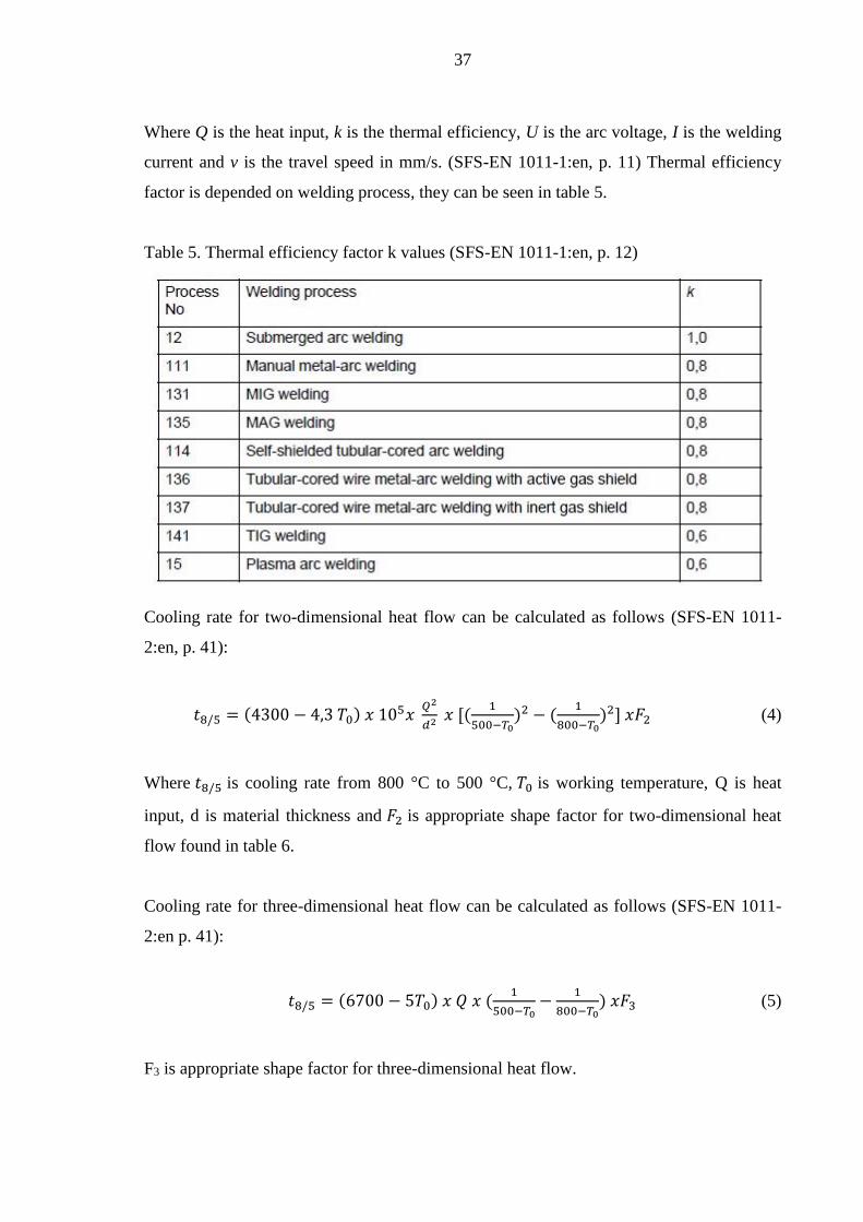
Where Q is the heat input, k is the thermal efficiency, U is the arc voltage, I is the welding
current and v is the travel speed in mm/s. (SFS-EN 1011-1:en, p. 11) Thermal efficiency
factor is depended on welding process, they can be seen in table 5.
Table 5. Thermal efficiency factor k values (SFS-EN 1011-1:en, p. 12)
Cooling rate for two-dimensional heat flow can be calculated as follows (SFS-EN 1011-
2:en, p. 41):
𝑡8/5 = (4300 − 4,3 𝑇0) 𝑥 105𝑥 𝑄2
𝑑2 𝑥 [(1
500−𝑇0)2 − (
1
800−𝑇0)2] 𝑥𝐹2 (4)
Where 𝑡8/5 is cooling rate from 800 °C to 500 °C, 𝑇0 is working temperature, Q is heat
input, d is material thickness and 𝐹2 is appropriate shape factor for two-dimensional heat
flow found in table 6.
Cooling rate for three-dimensional heat flow can be calculated as follows (SFS-EN 1011-
2:en p. 41):
𝑡8/5 = (6700 − 5𝑇0) 𝑥 𝑄 𝑥 (1
500−𝑇0−
1
800−𝑇0) 𝑥𝐹3 (5)
F3 is appropriate shape factor for three-dimensional heat flow.

38
Table 6. Shape factor values (SFS-EN 1011-2:en, p. 45)
4.5 Transition temperature & Brittle fracture
Non-alloyed and low-alloyed steels have microstructures that are mostly ferritic. Their
fracture behavior changes from ductile to brittle on certain temperature area, this is called
transition temperature. With low-alloyed steels this often occurs between temperatures of
+20 °C and -100 °C. (Huhdankoski, 2000, p. 8) At higher temperatures the absorbed
energy is relatively large with a ductile mode of fracture. As the temperature is lowered the
energy absorbtion drops over a relative narrow temperature range, below which the energy
has a small constant value and fracture mode is brittle. (Callister & Rethwisch, 2011, p.
251) Typical transition temperature curve of low-alloyed steel can be seen in figure 11.

39
Figure 11. Energy absorption transition curve of low-alloyed steel (replotted from
Kobelco, 2008, p. 8)
As mentioned, two kind of fractures can occur for metals, ductile and brittle. Classification
is based on the materials ability to experience plastic deformation. Fracture process has
two steps, crack formation and propagation. Typical characteristic for ductile fracture is
extensive plastic deformation in the vicinity of an advancing crack. The fracture process
proceeds relatively slowly as the crack length is extended. It resists further extension
unless the stress is increased. This kind of fracture process is often called stable. In
comparison brittle fracture may spread very rapidly with very little plastic deformation. No
applied stress is needed once the crack propagation will occurs, it will continue
spontaneously. (Callister & Rethwisch, 2011, p. 236)
Brittle fracture can occur as a grain boundary fracture or as a cleavage fracture. On
cleavage fracture, crack propagation happens with successive and repeated breaking of
atomic bonds along specific crystallographic planes. The fracture cracks pass through the
grains. On grain boundary fracture the crack propagation happens along the grain
boundaries. (Huhdankoski, 2000, p. 8; Callister & Rethwisch, 2011, p. 240-241)
Steels and weld metals resistance to brittle fracture can be evaluated by several fracture
toughness tests. Maybe the most common of these methods is Charpy-V notch impact test
(CVN). Other alternative methods include the crack-tip opening angle (CTOA), the crack-
tip opening displacement (CTOD), the drop-weight tear test (DWTT), the stress intensity

40
factor K, the elastic energy release rate G and the J-integral. (Callister & Rethwisch, 2011,
p. 250; Zhu & Joyce, 2012, p. 3; Huhdankoski, 2000, p. 12)
4.6 Weld imperfections and quality level
According to SFS-EN 6520-1 term imperfection means a discontinuity in the weld or a
deviation from the intended geometry. Weld defects are unacceptable imperfections.
Typical imperfections are for example cracks, cavities, solid inclusions, lack of fusion,
incomplete penetration and porosity. Some imperfections are allowed depended on
welding quality level. Three quality levels are given: B, C and D, where quality level B
corresponds to the highest requirement on the finished weld. (SFS-EN 6520-1, p. 8; SFS-
EN 5817, p. 11) Welding imperfections affect negatively to the joint properties and their
existence is always tried to minimize. Decision of quality level need to be done with
relation to application, expences and production time tend to rise with better quality level.
(Lukkari, 2001, p. 2)
4.6.1 Hydrogen cracking
Weld hydrogen cracking, also known as cold cracking, can occur to hardened
microstructure after welding. Hydrogen cracking usually occurs when the weld cools down
to temperature around 150 °C or sometimes even days after the welding is completed.
Non-alloyed steels, fine-grain steels, high strength steels, quenched and tempered steels
and heat resisting steels can all suffer hydrogen cracking but three causal factors need to
exist for hydrogen cracking to occur (Lukkari, 2001, p. 8):
- Sufficient amount of hydrogen absorbed in weld
- Hardened (martensitic) microstructure sensitive to cracking
- Elevated stress
Steel development has reduced the problem of hydrogen cracking in the HAZ and with
high strength steels the cracking is more of a problem in the weld metal. How the cracking
mechanism work is still under research but it is thought to relate to the diffused hydrogen
movement in the steel and its accumulation to the stress concentrations in the weld metal.
Hydrogen affects negatively to forces binding atoms and grains together and helps crack
formation. Main sources of dissolved hydrogen are atmospheric and welding consumable

41
moisture, impurities and hydrogen compounds in welding consumable and in base metal.
(Lukkari, 2005c, p. 44-46) Hydrogen scale of weld metal can be seen in table 7.
Table 7. Hydrogen scale of weld metal (SFS-EN 1011-2, p. 29)
The amount of hydrogen ending up in the weld metal differs creatly based on chosen
welding process and welding consumable as well as heat input. Higher heat input means
longer cooling time and more hydrogen can escape the weld pool by diffusion. (Lukkari,
2005c, p.49) Flux-cored consumables have normally hydrogen scales of B-D (SFS-EN
1011-2, p. 29)
Hydrogen cracking can be preventent by (Lukkari, 2005c, p. 44-45):
- Using a steel with low carbon content and carbon equivalent
- Using a TMCP steel
- Using a low hydrogen scale welding consumable
- Proper storage of welding consumables and base metals
- Cleansing the fusion face
- Using recommended heat input, given by steel manufacturer or standards
- Preheating
4.6.2 Hot cracking
Hot cracking, or solidification cracking, may occur on high temperatures during the
solidification of the weld metal. Such cracking is intergranular along the grain boundaries
of the weld. Solidification cracks are most commonly longitudinal centerline cracks but
they can appear on many locations and orientations. The cracks do not necessarily open to
the surface, they can also be buried. (Lukkari, 2001, p.6; Kou, 2003, p. 263)

42
Following factors affect the forming of hot cracking (Lukkari, 2001, p. 6):
- Shape of the weld bead
- Metallurgical factors such as chemical composition, the amount of impurities and
the extent of weld metal solidification area
- Strain factors
A concave shaped weld bead is more prone to suffer solidification cracking than a convex
shaped. The outer surface of a concave shaped weld bead is stressed in tension when the
weld cools and shrinks. The outer surface of the weld is being pulled towards the toes and
the root as seen in figure 12. If the weld is convex shaped, pulling towards the root
compresses the outer surface and offsets the tension caused by pulling towards the toes.
The tensile stresses are reduced along the outer surface and so is the tendency to
solidification cracking. Excessive convexity can however produce stress concentrations
and other forms of cracking. (Kou, 2003, p. 294)
Figure 12. The effect of weld bead shape (Kou, 2003, p. 294)
Weld width to depth ratio can also effect the solidification cracking. If the weld bead shape
is deep and narrow, as seen in figure 13, it can be susceptible to centerline cracking. This is
because the angle of the abutment between the columnar grains growing from opposite
sides of the weld pool is too steep. This will also help the impurities to segregate in the
center of the weld pool in the final stages of solidification and form low melting point
compounds. Cracks will occur easier in the centerline of weld when the tensile stresses
start to develop, if there are still partly liquid films at grain boundaries. (Lukkari, 2001, p.
6; Kou, 2003, p. 268, p.294) Some research has also proven that narrower gap is more

43
prone to suffer solidification cracking. It was also observed that these cracks were healed
by remelting of the following overlapping passes. (Karhu & Kujanpää, 2011, p. 173-174)
Figure 13. Effect of weld depth-width ratio on centerline cracking (Kou, 2003, p. 295)
Tendency to hot cracking can be estimated with the unit of crack susceptibility (UCS)
formula developed by The Welding Institute (TWI). It was originally developed for
submerged arc welding but can also be used with other welding processes. UCS is
calculated in relation to composition of the weld metal as follows. (Lukkari, 2001, p.8;
Vähäkainu, 2003, p. 45)
𝑈𝐶𝑆 = 230𝐶 + 190𝑆 + 75𝑃 + 45𝑁𝑏 − 12,3𝑆𝑖 − 5,4𝑀𝑛 − 1 (6)
The formula is valid for weld metal containing following concentrations seen in table 8 and
table 9.
Table 8. Validity of the UCS formula (SFS-EN 1011-2, p. 93)

44
Table 9. Limits of alloying elements and impurities (SFS-EN 1011-2, p. 95)
As the UCS formula is calculated results can be estimated as follows (Lukkari, 2001, p. 8;
Vähäkainu, 2003, p.45):
UCS = <10 High resistance to cracking
UCS = 10-30 A risk of cracking with low weld bead width/depth ratio
UCS = >30 Low resistance to cracking
Hot cracking can be prevented by (Vähäkainu, 2003, p. 44; Lukkari, 2001, p. 7; Kou, 2003,
p. 294; SFS-EN 1011-2, p. 93):
- Adjusting welding parameters so that weld width to depth ratio is 1:1 or more
- Designing the weld joint so that strains will be minimal
- Cleaning the impurities and slag from welding faces
- Choosing steel with low carbon content
- Avoiding base materials with over 0,04 % sulphur and phosphorus content
- Reducing penetration and welding speed
- Avoiding concave shaped welds

45
5 QUALITY ASSURANCE OF FC-NGAW
Quality requirements for welded structures are set out in different directives, regulations,
standards or customer specification. Quality systems standard such as ISO 9001 defines
welding as special process or as process requiring validation that must be properly
controlled to ensure that the necessary quality requirements are achieved. (Weman, 2003,
p. 171) Actual quality requirements for welding are presented in ISO 3834 standards. This
standard can be used as a quideline to provide assurance of welding competence. ISO 3834
consists of six parts. Different quality requirement levels: comprehensive quality
requirements, standard quality requirements and elementary quality requirements are found
on parts 2-4. (Martikainen, 2013, p. 7) All the quality requirement levels have some
common demands (Martikainen, 2013, p. 7; Martikainen, 2010, p. 181):
- Welding coordination must be defined
- The welders and welding operators must have been tested and approved
- The NDT personnel need to be qualified and approved
- The welding need to ne carried out in accordance to welding procedure
specifications (WPS)
- The consumables need to be stored and handled properly
- Identification and traceability of welding consumables and products
The differences between quality requirements of ISO 3834-2 and ISO 3834-3 are slight
and mostly related to documentation, which is stricter on ISO 3834-2. (Martikainen, 2013,
p. 7) Table 10 shows the relationship between demands of different quality requirement
levels.

46
Table 10. The relationship of requirements between different quality requirement levels
(SFS-EN ISO 3834-1, p. 15)

47
5.1 Quality factors
Welding quality factors can be divided into two very different scale aspects: technical
quality of a weld and operational welding quality. Technical quality of a weld is
considered sound when it meets the given requirements. Usually the customer is the party
who sets these requirements but sometimes the welded product can define the requirements
on its own. Such products could be off-shore structures, nuclear power plant structures,
pressure vessels, bridges, cranes and so on. The authorities and classification societies can
also set requirements and nowadays it is common that even the producer can set
requirements by itself. (Martikainen, 2013, p. 5)
Technical quality of a weld can be presented as follows (Martikainen, 2013, p. 5):
- Visual quality
- Basic workshop quality
- Weld class quality
- Metallurgical quality
Visual quality and basic workshop quality as a concepts do not define the quality level
very strictly. Still the importance of the visual quality of the weld has been emphasized
lately. Surface of the weld has to be smooth and flawless and without restart points. In
simple terms it needs to look good. Basic workshop quality can be achieved with
competent personnel and equipment. It can be compared to quality level C or IIW
(International Institute of Welding) 3 without incomplete penetration. (Martikainen, 2013,
p. 5)
Weld classes are defined more clearly and weld in such level will have to meet the certain
welding imperfection requirements. Welding imperfections are described in EN ISO 6520-
1 and related quality levels B, C and D for steels in EN ISO 5817. New quality level
designed as B+, which has additional requirements is described in EN 1090. Different weld
classes do not in anyway define the metallurgical factors or properties of the welded joint.
The joint can have no welding imperfections but still be unusable in its application. The
microstructure needs to be tough enough, grain size next to the fusion line cannot be too
large, too hard or too soft zones are not permitted and so on. These kind of factors cannot

48
be detected with ordinary NDT. Welding procedure test must be done to be able to verify
these factors and WPS is a great aid for quality control. (Martikainen, 2013, p. 5-6)
By focusing solely on technical quality it’s hard to see the big picture. Operational welding
quality takes widely into account factors affecting to quality before, during and after
welding. When productivity and economy related things are also included, a TQM (Total
Quality Management) model is the result. It’s a comprehensive way where all the things
form a solid base for action. (Martikainen, 2013, p. 6-7)
5.2 Welding procedure test
Welding procedure test is the most common method to gain approval for the WPS. A
standardized test piece is made representing the welded joint in relation to production. The
shape and dimensions of the test piece need to be sufficient for allowing all the required
tests to be carried out. Testing includes both non-destructive testing (NDT) and destructive
testing (DT), testing is summarized in table 11. (SFS-EN ISO 15614-1, p. 13 & 19)
Table 11. Examination and testing of the welded test pieces (SFS-EN ISO 15614-1, p. 21)

49
Test specimen shall be taken after the NDT is carried out. It is also acceptable to take the
specimen from locations avoiding welding imperfections located by NDT. (SFS-EN ISO
15614-1, p. 21) Test specimen locations for butt joint in plate can be seen in figure 14.
Figure 14. Test specimen locations of butt joint in plate (replotted from SFS-EN ISO
15614-1, p. 23)
5.3 Testing methods
Testing methods can be separated into non-destructive testing and to destructive testing
methods. Non-destructive testing is used to check if the quality demands are being met.
NDT methods cause no damage to the test piece and can find many kind of welding
imperfections. Destructive testing is used when mechanical properties and metallurgical
quality of the test piece are needed to found out.

50
5.3.1 Non-destructive testing
The most common way of NDT is visual testing (VT). Human eye can detect line shaped
imperfection about 0,05 mm in width and circular imperfection about 0,10 mm in diameter.
Optical instruments such as magnifying glasses and macroscopes can be used. Even though
the method is simple to use, rules, guide books, contrasting items and clear limits for
approval are needed to make this method reliable. (Martikainen & Niemi, 1993, p. 27-30)
Liquid penetrant testing is a surface testing method, used to detect discontinuities in the
surface of non-porous materials. It is suitable also for non-magnetic materials. The test
piece is carefully cleaned after which a colored or fluoroscent liquid is poured on the
surface, a capillary force helps the liquid to penetrate the discontinuities. After certain
amount of time the liquid is washed away and a developer is introduced. Some of the still
present penetrant liquid is absorbed into the developer and information is obtained about
the discontinuity. (Martikainen & Niemi, 1993, p. 30)
Magnetic particle testing is also a surface testing method, used to reveal discontinuities in
or in the immediate vicinity of the surface of ferromagnetic materials. Fine ferrous iron
particles are set on the surface of the piece and the piece is then magnetized. The magnetic
field introduced is composed of magnetic lines of force. Flaws and imperfections interrupt
the flow of the magnetic lines and the ferrous particles gather around these points exposing
the flaws. If the discontinuity is presicely same way oriented as the magnetic lines of force,
it cannot be discovered. Magnetic particle testing should always be done twice in
downright directions. (Martikainen & Niemi, 1993, p.32)
Radiographic testing covers all the photographic methods using ionizing radiation and it
can be used to reveal many kind of internal flaws. An appropriate measuring instrument,
usually film is placed behind the test piece. The test piece is then exposed to radiation and
the intensity of the rays penetrating is stored on the measuring instrument. Radiograph of
the piece is then processed and interpreted to discover information about the present flaws.
Three-dimensional flaws such as porosity, slag inclusions and defects in form can be
found, if their size is at least 1-2 % of the material thickness. (Martikainen & Niemi, 1993,
p. 35)

51
Radiographic testing with X-rays is very usable method up to 50 mm material thicknesses.
The sensibility of the equipment is commonly 2-3 % of the material thickness. Over 50
mm thick materials need to be tested with different radiation sources. (Martikainen &
Niemi, 1993, p. 35)
Ultrasonic testing is a method which utilizes high frequency sound waves usually between
0,5 and 20 MHz range. The sound waves travel through the material and their intensity is
measured after reflection. The presence and location of the flaw can be determined from
the reflection. The higher the frequency used the smaller the flaws that can be detected.
The penetrating ability suffer the higher the frequency used though. (Martikainen & Niemi,
1993, p. 36)
5.3.2 Destructive testing
Hardness test provides information about the metallurgical changes caused by welding.
Three different commonly used hardness tests are the Brinell, Rockwell and Vickers.
(Connor, 1987, p. 394) The Brinell test uses a steel ball of known diameter as identer
which is forced into material by specified force. The diameter of the impression is then
measured and converted to Brinell hardness number, so the hardness value is calculated as
a load per area. The Vickers test is similar but uses smaller inverted pyramid as identer
which is ideal for measuring different zones of microstructure. The Rockwell test measures
hardness through depth of penetration which the identer causes on set force. (Bruce et al.,
2004, p. 36-37) The hardness identations can be done at regular intervals or as a single
indentations (SFS-EN ISO 9015-1, p. 9).
Impact test measures the impact strength of a test piece. The test shall be carried out in
specified temperature because the impact values of metallic materials can vary with
temperature. The most common impact test method is the Charpy V-notch impact test. A
standard sized notched test piece is hit by a swinging pendulum and the amount of energy
absorbed is measured. Specimen for Charpy impact test is usually 55 mm long and 10 mm
and of square section with 10 mm sides with V- or U-shaped notch in the center of the
length as seen in figure 15. (SFS-EN ISO 148-1, p. 11)

52
Figure 15. Charpy impact test princible (Adapted from SFS-EN ISO 148-1, p. 19)
Tensile test is performed to stress the test specimen to the breaking point. An increasing
tensile load is applied to the test specimen on a machine until the rupture occurs. The result
is stress-strain diagram which can be interpreted to discover the yield strength, tensile
strength and percent elongation. (Bruce et al., 2004, p. 32-35; SFS-EN ISO 4136, p. 9)
Tensile test can be transversal or longitudal. The purpose of the transversal tensile test is to
verify that certain design strength requirements are met. (Connor, 1987, p. 389)
Various types of bend tests are used to evaluate the ductility of a welded joint.
Transversely or longitudinally taken test specimen from the welded joint is submitted to
plastic deformation by bending it, without reversing the bending direction. (SFS-EN ISO
5173/A1, p. 11) Either the weld surface area or the weld cross section is made under
tension in order to expose flaws (Connor, 1987, p. 395).

53
5.4 WPQR and WPS
Welding procedure specification (WPS) is a formal written document that specifies the
details of the required variables for a specific application in order to assure repeatability. It
must contain all important information relating to the welding work and with indication
whether such factors can affect the metallurgy, mechanical properties or geometry of the
welded joint. WPS forms a sound base for planning, execution and quality assurance of
welding. (Weman, 2003, p. 176; Lukkari, 2002, p. 55; SFS-EN 15609-1, p. 7) At least
following information is required in WPS (Lukkari, 2002, p. 55):
- Identification of the manufacturer
- Identification of the WPS
- Reference to the welding procedure qualification record (WPQR)
- Designation of the material
- Thickness ranges of the joint
- Welding process
- A sketch of the joint design
- Weld run sequence (given on the sketch if essential)
- Applicable welding positions
- Joint preparation methods
- Welding parameters
- Welding consumables
- Heat input and preheating
- Interpass temperature
SFS-EN ISO 15609 gives all the required information needed in WPS. New welding
processes or materials usually aren’t applicable with old welding procedure specification
and need to be tested with some of the methods listed in SFS-EN ISO 15607. Until the
WPS is proven that way it is considered pWPS or preliminary welding procedure
specification. (Weman, 2003, p. 176; Lukkari, 2002, p. 55; SFS-EN 15609-1, p. 7) If the
results are satisfactory and proven, welding procedure qualification record (WPQR) is
made. WPQR is a document specifying all the needed information about the welding and
the results of the testing performed for the weld. (SFS-EN ISO 15614-1, p. 47)

54
5.5 Comparison of RMRS procedures of testing to EN
The test piece for butt welded joint in plate according to RMRS is shown in figure 16.
Symbols a and b are dimensions depending on a welding process. These rules apply for
manual and semi-automatic welding: a ≥ 150 mm but not less than 3 times material
thickness, b ≥ 350 mm but not less than 6 times material thickness. For automatic welding,
a ≥ 200 mm and b ≥ 1000 mm. Number 1 is orientation of rolling direction for plates
impact tested in the longitudinal direction KVL and number 2 is orientation of rolling
direction for plates impact tested in the transverse direction KVT.
Figure 16. Test piece for butt welded joint in plates according to RMRS (Russian Maritime
Register of Shipping, 2014b, p. 126)
Corresponding test piece according to SFS-EN ISO 15614-1 is shown in figure 17.
Minimum value for a is 150 mm and minimum value for b is 350 mm, t being the material
thickness and number 1 referring to joint preparation and fit-up as detailed in pWPS. EN
rules do not specify different dimensions for automatic welding.

55
Figure 17. Test piece for a butt welded joint in plate with full penetration according to EN
rules (SFS-EN ISO 15614-1, p. 15)
Required testing methods according to RMRS are shown in table 12. The EN requirements
are similar except only 2 series of impact test specimens are needed. The extent of impact
testing according to RMRS depends on thickness of the test piece, the heat input of
welding and grade of the base material. Charpy-V notches need to be in weld metal, on
fusion line and in HAZ, 2 mm from fusion line. Additional notches may be required in
HAZ, 5 and 10 mm from fusion line.

56
Table 12. Requirements of testing for butt joints according to RMRS (Russian Maritime
Register of Shipping, 2014b, p. 128)
Type of test Extent of testing
Visual testing 100 %
Radiographic or ultrasonic testing 100 %
Surface crack detection 100 %
Transverse tensile test 2 specimens
Transverse bend test 4 specimens Impact test Minimum 3 series
of 3 specimens
Hardness test Required
Macro examination 1 specimen
RMRS impact strength requirements are shown in table 13.
Table 13. Impact strength requirements of different steel grades welded on vertical position
for butt joints according to RMRS (Russian Maritime Register of Shipping, 2014b, p. 136)
Steel grade
Impact energy in J (min.)
Weld
HAZ and FL
Longitudinal Transverse
A32-F32 34 47 -
A36-F36 34 47 -
A40-F40 39 47 -
A420-F420 42 42 28
A460-F460 46 46 31
A500-F500 50 50 33
A550-F550 55 55 37
A620-F620 62 62 41
A690-F690 69 69 46
Hardness requirements for higher and high strength steels also differ a bit from EN as seen
in table 14. Heat treatment of high strength steels must be consulted with Register.

57
Table 14. Limiting hardness values for high strength steels (SFS-EN ISO 15614-1, 2012, p.
33; Russian Maritime Register of Shipping, 2014b, p. 135)
Rules Non-heat treated
Heat treated
SFS-EN 15614-1 380 (HV10) 320 (HV10)
RMRS 420 (HV10) -
There is also some deviation between RMRS and EN in range of approval for butt welds
material thickness. Comparison of qualification ranges is shown in table 15.
Table 15. RMRS and EN comparison of qualification ranges for butt welds material
thicknesses (SFS-EN ISO 15614-1, 2012, p. 41; Russian Maritime Register of Shipping,
2014b, p. 141)
Rules Test piece
thickness (mm)
Range of qualification
Single run Multi run
EN t ≤ 3 0,7t - 1,3t 0,7t - 2t
3 < t ≤ 12 0,5t (min. 3) - 1,3t 3 - 2t
12 < t ≤ 100 0,5t - 1,1t 0,5t - 2t
t > 100 not applicable 50 -2t
RMRS t ≤ 3 t - 1,1t t - 1,5t
3 < t ≤ 12 0,7t - 1,1t 3 - 2t
12< t ≤ 100 0,7t - 1,1t 0,5t - 2t (max. 150)
t > 100 - 0,5t - 2t

58
6 EXPERIMENTAL TESTING
The experimental part of the thesis aims to clarify, if narrowed gap welding with
mechanized flux-cored arc welding and further reducing groove angles is qualitative
possible. Certain factors have to be taken into account when welding high strength steels to
achieve good mechanical properties of the welded joint. In this case the limiting factor was
heat input, which was limited to value 2 kJ/mm that the steel producer and Russian
Maritime Register of Shipping recommend.
Twelve different test pieces were welded on vertical upwards position (PF) during the
testing period and their weld joint qualities were tested with NDT and DT methods. These
test results are used as a foundation for an official welding procedure test performed later
on in supervision of Maritime Register of Shipping.
6.1 Experimental plan
Arctech Helsinki Shipyard has earlier done welding tests with 30° groove angle and the
results were succesful. Preliminary testing plan was made at the beginning of the
experimental testing period, it can be found in Appendices 3 and 4. Three different groove
angles were chosen to be tested, these were 20, 10 and 5 degrees. Some test pieces were
also welded with identical groove angle, but with different root opening. Finally one test
piece was welded without mechanization to provide some comparison. The idea was to use
two different shielding gases, pure CO2, a mixture of argon and CO2 (M21) and
appropriate filler materials. The availability of Wise welding software solutions was also
utilized with E500 TMCP steel.
The goal was to find optimal welding parameters and to achieve clean quality weld pieces,
which were later tested with destructive testing methods at Lappeenranta University of
Technology Welding laboratory. The main goal of the experimental testing was to achieve
welding procedure qualification record (WPQR) and preliminary welding prodecure
specification (pWPS) for the tested steels.

59
6.2 Testing materials and welding tests
Two shipbuilding steels were chosen to be tested, they were Ruukkis’s E500 TM and
EH36. They are commonly used at the Shipyard and both are E grade steels, meaning that
their impact strength test temperature is -40°C. E500 TM was delivered 25 mm thick
where EH36 was delivered 10 mm thick. E500 TM is thermomechanically treated and
EH36 is normalized. Chemical composition and mechanical properties of the steels are
shown in tables 16 and 17.
Table 16. Chemical compostion of the steels (Test certificates, Appendix 5 & 6)
Chemical composition %
Steel Thickness Pcm C Si Mn P S Al Nb V Ti
E500 TM 25 mm 0,18 0,068 0,26 1,50 0,011 0,001 0,047 0,036 0,008 0,015
EH36 10 mm 0,27 0,169 0,39 1,44 0,022 0,003 0,026 0,001 0,032 0,003
Steel Thickness Cu Cr Ni Mo N B Sn Pb - -
E500 TM 25 mm 0,271 0,05 0,75 0,008 0,004 0,003 0,002 - - -
EH36 10 mm 0,07 0,08 0,03 0,006 0,005 - - - - -
Table 17. Mechanical properties of the steels (Test certificates, Appendix 5 & 6)
Mechanical properties
Steel Yield strength (Mpa) Tensile strenght (Mpa) Elongation (%) Impact test (J)
E500 TM 575 657 17 309 (-40°C)
EH36 409 574 23,5 74 (-40°C)
Welding consumables selected were Filarc PZ6113, Filarc PZ6115 and Dual Shield II 91-
LT. PZ6113 was chosen because it is commonly used and it is also suitable for both pure
CO2 as well as M21 shielding gas. EH36 steel welding tests were performed with PZ6113.
Filarc PZ6115 was used for welding E500 TM steel with M21 shielding gas and Dual
Shield II 91-LT was a new welding consumable, delivered specifically to be used with
E500 TM steel and 𝐶𝑂2 shielding gas. All consumables are rutile cored wires and 1,2 mm
in diameter. PZ6113 and PZ6115 are both designed to be used with positional welding.
PZ6113 produces softer arc than PZ6115, further information about the consumables is
shown in tables 18 and 19. Shielding gases were M21 80% Ar + 20% 𝐶𝑂2 and pure CO2.
Kerback FS 271412 T flat ceramic backing was also used.

60
Table 18. Chemical composition of the welding wires (Test certificates, Appendix 7)
Chemical composition [%]
Wire C Mn Si S P Cr Ni Mo Nb Cu V
DS II 91 LT 0,05 1,06 0,35 0,008 0,014 0,02 2,23 - - - -
PZ6115 0,05 1,00 0,37 0,017 0,017 - 2,50 - - - -
PZ6113-1* 0,05 1,20 0,49 0,020 0,011 <0,1 <0,1 <0,1 0,01 0,02 0,02
PZ6113-2* 0,05 1,20 0,50 0,021 0,014 <0,1 <0,1 <0,1 0,01 0,01 0,02
* two different manufacturing batches of PZ6113 were used
Table 19. Typical mechanical properties of the welding wires (Test certificates, Appendix
7; Esab, 2014, p. 2; Lukkari, 2005a, p. 6)
Typical mechanical properties
Wire Yield strength (Mpa) Tensile strength (Mpa) Elongation (%) Impact test (J)
DS II 91 LT 568 643 24 89 (-40°C)
PZ6115 560 620 24 60 (-50°C)
PZ6113 505–535 571–601 25 128 (-20°C)
The butt welded test pieces were made of two plasma cutted 40 by 20 cm sized steel plates.
Material thicknesses were 25 mm for E500 TM steel and 10 mm for EH36 steel. 20° and
10° groove angles were machined at shipyards own machine tooling shop and 5° groove
angle was achieved with the plasma cutting, no machining was necessary. Before welding,
fusion faces were grinded to clean them from impurities. The cutted and machined test
pieces were tack welded with planned root openings and ceramic backing strip was
fastened. Finally the test piece was fastened to a custom made rack where the welding
carriage and rails were located. The welding was done by highly skilled Arctech Helsinki
Shipyard welder.
Welding tests were started by acquiring proper welding parameters for each test
configuration. Shielding gas flow was measured and set to 18 litre per minute. The root
pass of all test pieces was welded with slightly pushing torch angle and with short stopping
time in oscillation motion to achieve good fusion. Short stopping time was also used in
final run to assure a good weld bead shape. Both WisePenetration and WiseFusion
processes were used with E500 TM steel test pieces, except with the 20° groove angle
where WiseFusion was only used in the root pass. EH36 steel test pieces were welded
without the Wise processes. Welding parameters for each test piece were documented and
the records can be found in Appendix 8.

61
6.2.1 Welding tests with E500 TM steel
No major problems occurred during welding the E500 TM test pieces with M21 shielding
gas. WisePenetration and WiseFusion software solutions were active during the welding,
except when welding the 20° groove angle test piece, where WiseFusion was only used in
root pass. Welding the following beads without WiseFusion was done in experimental
purpose. WiseFusion keeps the arc length optimally short and makes the arc alignment
easier in narrower groove. It was noticed during the welding tests that, the narrower the
groove, the more the arc started to wander closer the groove faces, if WiseFusion was not
active. It was, however, possible to weld the subsequent weld beads of the 20° groove
angle test piece without WiseFusion. With narrower groove angles the benefits of Wise
processes was emphasized. More precision was needed and careful adjusting of oscillating
width, but in general the welding was successful. It must be mentioned though that highly
skilled operator is needed to achieve good results with narrower groove angles.
Welding with the CO2 shielding gas and Dual Shield II 91-LT flux-cored wire was
problematic. The root pass was extremely good, but welding the following weld beads
resulted in excess penetration and inadequate fusion with the groove faces. These problems
were not able to be solved during the testing period, although welding parameter tuning
and other factors were tested. The penetrative nature of the wire was so dominant, that
successful test piece could not be achieved and the testing was decided to postpone.
6.2.2 Welding tests with EH36 steel
All in all the welding tests with EH36 steel and both shielding gases were successful. The
material thickness of the steel plates was 10 mm, so welding parameters were a bit lower
and not that many welding beads were needed to fill the joint. Wise processes were not
used to have some comparison on welding quality.
The welding of test pieces with 20° and 10° groove angles and M21 shielding gas was
successful eventhough more adjusting was needed by the welding operator during the
welding. The narrowest groove with 5° groove angle and 6 mm root opening caused
problems. The result was incomplete fusion with groove faces and eventually the wire
pushed the ceramic backing strip out of its position. Next test piece was made with larger,

62
9 mm root opening and that solved the problem. The failure of the first test piece may have
been a result of distortions, to be precise, bending of the test piece during the welding. The
bending might have caused the joint geometry to change, so that the groove got even
narrower than it supposed to be.
Welding with CO2 shielding gas proved no difficulties. Same Filarc PZ6113 flux-cored
wire was used, it has good welding properties and it is suitable for both shielding gases.
The test piece with the narrowest groove angle was again prepared with 9 mm root opening
and suffered no shortcomings during welding. Because of the welding tests with CO2
shielding gas and E500 TMCP steel were unsuccessful an extra test piece of EH36 steel
was welded without mechanization.
6.3 Non-destructive and destructive testing
Non-destructive testing was done at the Arctech Shipyard’s premise. Visual testing was
performed after welding to make certain that welds are good quality. After the visual
testing all test pieces were tested with magnetic particle testing. This test was performed by
personel from Dekra Industrial. Finally test pieces were sent to radiographic testing, where
X-ray photos were taken. The photos were taken and analyzed by Dekra personnel. More
information of the non-destructive testing is found on the results section of the thesis.
After non-destructive testing was approved, the test pieces were shipped to Lappeenranta
University of Technology welding laboratory, where test specimens were produced for
destructive testing. Test pieces were first cut with bench saw to proper blanks. Tensile test
specimens were machined to proper dimension according to SFS-EN ISO 4136. Three
series of impact test specimens were machined per test piece according to SFS-EN ISO
148-1. E500 TMCP steel impact test specimens dimensions were standard 10x10x55 mm
but EH36 steel test specimens had to be made subsidiary with dimensions of 7,5x7,5x55
mm. Impact test temperature was -40°C for the E500 TMCP steel test specimens and -
20°C for the EH36 steel test specimens.
Final runs of the bend test specimens were grinded to same level with the base material and
then tested with side bend test according to SFS-EN ISO 5173. Macro test specimens were
grinded, polished and then etched before examination and photography. Hardness tests

63
were performed with automatic Struers DuraScan 70 hardness testing machine. E500
TMCP test specimens’ surface, middle and root were measured with rows of identations,
where EH36 test specimens’ surface and middle was measured.

64
7 EQUIPMENT
All welding equipment and necessary materials were provided by Arctech Helsinki
Shipyard. All the test welding was done in Shipyard´s premise. Welding equipment which
was used was Kemppi Fastmig X 450 power source and FastMig MXP 37 Pipe wire
feeding unit. The power source was equipped with latest editions of Kemppi’s
WisePenetration and WiseFusion welding software solutions. WisePenetration and
WiseFusion can be adjusted in one of the submenus of the power source control panel.
Power source and wire feeding unit can be seen in figure 18.
Figure 18. Kemppi wire feeding unit and power source
Welding was mechanized with the aid of Esab railtrac welding carriage and rails. A remote
control unit was used to do necessary guidance correction during welding. Mechanization
devices are shown in figures 19 and 20. Assembled welding setup is shown in figure 21.

65
Figure 19. Esab welding carriage on rail with mounted welding gun
Figure 20. Esab railtrack control unit and remote control

66
Figure 21. Welding setup with fastened and welded test piece

67
8 RESULTS AND DISCUSSION
A review of the results is shown in this chapter. Non-destructive testing results are
examined before destructive testing and finally a preliminary welding procedure
specification is presented based on the performed narrow gap welding tests. Test
specimens identifier and legend is shown in table 20.
Table 20. Identifiers and legend of the different test specimens
Identifier Steel Groove angle (°) Root opening (mm) Shielding gas Mechanization
B56M E500 TM 5 6 M21 x
B59M E500 TM 5 9 M21 x
B106M E500 TM 10 6 M21 x
B109M E500 TM 10 9 M21 x
B206M E500 TM 20 6 M21 x
A59C EH36 5 9 CO2 x
A59M EH36 5 9 M21 x
A59MK EH36 5 9 M21 -
A106C EH36 10 6 CO2 x
A106M EH36 10 6 M21 x
A206C EH36 20 6 CO2 x
A206M EH36 20 6 M21 x
8.1 Non-destructive testing
Test pieces were visually inspected after welding by welder in adequate lighting. Visually
welds looked great and had good shape on both sides. Some test pieces had low amount of
spatter but no major flaws were detected. Magnetic particle testing was performed to all
test pieces after visual testing. Testing was carried out by personnel from Dekra Industrial.
No flaws were detected during testing and all the test pieces passed qualitative demands of
EN rules. Ongoing magnetic particle testing is shown in figure 22.

68
Figure 22. Ongoing magnetic particle testing
Finally test pieces were sent to radiographic testing. It was discovered, that the weld
quality was excellent through the length of the welds. Only the test piece which was
welded without mechanization had lack of fusion on a single point in the top of the test
piece. An example photo of radiographic testing is shown in figure 23.
Figure 23. Radiographic photo of one of the test pieces

69
8.2 Bend testing
Bend testing was carried out using transverse side bend test for E500 TM and transverse
root and face bend test for EH36 steel. All test specimens of both steels were bended to
180° angle. According to SFS-EN 15614-1, the test specimen shall not reveal any single
flaw greater than 3 mm in any direction. No flaws occurred to any of the test specimens
during testing and target bend angle was achieved with each test specimen. Test specimens
proved to be very ductile and as expected free from imperfections. Full records of the bend
testing are shown in Appendix 9.
8.3 Impact testing
Impact testing was considered to be one of the crucial test methods. Shipbuilding steels
have strict rules for toughness to prevent failures in ship structures. Impact testing was
carried out as Charpy-V test method. According to SFS-EN 15614 the absorbed energy
shall be in accordance with appropriate parent material standard and for each notch
location one individual value can be below the average value specified, but not less than 70
% of the specified value. Average values of impact testing are shown in figures 24 and 25.
Groove angle (in degrees), root gap (in mm) and shielding gas (if varies) are marked on the
figures. Complete impact test records are shown in Appendix 10.
Impact test results for E500 TM steel test specimens were really good. The results are
pretty consistent on the weld metal which is due to similar welding parameters and
mechanization were used. Better test results were achieved with 6 mm than with 9 mm
groove gaps. All test specimens exceeded 50 J minimum value on weld metal set by
RMRS. The lowest measured E500 TM impact strength value on weld metal was 52 J and
the highest was 85 J. Deviation between single values on weld metal was below the 70 %
average limiting value. However more deviation is noticeable in HAZ values, where a
single test specimen of B206M fails to qualify to the 70 % rule.

70
Figure 24. Average impact test results of E500 TM test specimens welded with M21
shielding gas
EH36 steel test results were surprisingly good considered that the testing of specimens was
done at lower temperature, than what the filler metal is designed for. The limiting values
according to RMRS for EH36 steel are 34 J on weld and 47 J in HAZ and on fusion line.
As seen in figure 25, some of the results are close to the limiting values. Difference of
manual welding and mechanization is clear. The manual welded test piece (A59MK) has
lower average impact strength value and also the single specimen results were worse than
those welded with mechanization. The average impact strength values do not show the
whole truth, because there was much variation between single test specimens and many
were under 70 % of the average impact strength value. The lowest measured impact
strength value of EH36 was 37 J for test piece with mechanized welding and 20 J for
manual welded test specimen.
77 68 7860
79
269
175
210
104
218
0
50
100
150
200
250
300
5°, 6mm 5°, 9mm 10°, 6mm 10°, 9mm 20°, 6mm
[J]
E500 TM impact test results at -40 °C
Weld HAZ RMRS limit weld&HAZ

71
Figure 25. Average impact test results of EH36 test specimens (Manual welded test
specimen marked with hand, the rest of the test pieces were welded with mechanization)
8.4 Tensile testing
Transversal tensile tests were done to find out yield strength, ultimate strength and
percentage elongation of test specimens. According to SFS-EN ISO 15614 the tensile
strength of the test specimen shall not be less than the corresponding specific minimum
value for the parent metal. As seen in material certificates both steels had strength values
above the minimum values set by the standard and also the measured strength values of the
welded test specimens exceeded the minimum parent metal values. Also the tested
elongation values of both steels test specimens were above the limiting values set by
RMRS.
All of the EH36 test specimens broke from the base material, but there was some variation
where the E500 TM test specimens fractured. Due to malfunction with the test setup, not
all of the EH36 steel test specimens could be tested, but atleast one of each test specimen
per test piece was tested. Average tensile test results are shown in figures 26 and 27.
Groove angle (in degrees), root gap (in mm) and shielding gas (if varies) are marked on the
figures. Test pieces that had only one tensile test specimen tested are marked with * in the
figure. RMRS limits for ultimate strength were 610 MPa for E500 grade and 490 MPa for
EH36 grade. Complete test records are shown in Appendix 11.
50 4735
50 5347
5649
132
50
7263
8578
0
20
40
60
80
100
120
140
5°, 9mm,M21
5°, 9mm,CO2
5°, 9mm,M21, hand
10°, 6mm,M21
10°, 6mm,CO2
20°, 6mm,M21
20°, 6mm,CO2
[J]
EH36 impact test results at -40 °C
Weld HAZ RMRS limit weld RMRS limit HAZ

72
Figure 26. Tensile test results of E500 TM steel welded with M21 shielding gas
Two of the EH36 test specimens welded with CO2 shielding gas had lower strength values
compared to specimens welded with M21 shielding gas mixture. Interestingly the test
specimen with 5° groove angle, 9 mm root gap and CO2 was an exception and had similar
strength values compared to the test pieces welded with M21 shielding gas mixture. One of
the test specimens barely exceeds the RMRS limit of 490 MPa.
Figure 27. Tensile test results of EH36 steel
577 577 574
558567
661 657664
630
645
500
520
540
560
580
600
620
640
660
680
5°, 6mm 5°, 9mm 10°, 6mm 10°, 9mm 20°, 6mm
[MPa
]
Yield strength Ultimate strength RMRS limit Ultimate strength
389 395 396 387
360
385370
530543 541 540
493
536512
300
350
400
450
500
550
600
5°, 9mm,M21 *
5°, 9mm,CO2
5°, 9mm,M21,
manual *
10°, 6mm,M21
10°, 6mm,CO2 *
20°, 6mm,M21
20°, 6mm,CO2 *
[MPa
]
Yield strength Ultimate strength RMRS limit Ultimate strength

73
8.5 Hardness and macro testing
Row of identations were used to measure hardness values from base material, HAZ, fusion
line and weld metal. All measured hardness values were below the limiting values of 380
HV10 and 420 HV10 for multipass welds according to EN 15614-1 and RMRS. Due to
variation in weld shape and HAZ width between different test specimens, the amount of
measuring points per test specimen also varies. Root hardness values of E500 TM are
shown in figure 28 and surface hardness values of EH36 are shown in figure 29. The
horizontal axis in the figures (location of the measuring point) is a guideline, complete test
records are shown in Appendix 12. Majority of the peak hardness values are in root and
surface HAZ. Middle of thickness values were lower, because of the heat treatment of
subsequent weld beads.
Figure 28. E500 TM hardness values measured from the root
Average E500 TM base material hardness was about 206 HV5 and average weld metal
hardness was about 225 HV5. Corresponding values for EH36 were about 173 HV5 for
base material and about 203 HV5 for weld metal. For both steels, the majority of the
highest measured hardness values were in HAZ. Single highest hardness values were 259
HV5 for E500 TM steel and 247 HV5 for EH36 steel.
180
190
200
210
220
230
240
250
260
270
HV
5
E500 TM root hardness
5°, 6mm 10°, 6mm 20°, 6mm 5°, 9mm 10°, 9mm

74
Figure 29. EH36 hardness values measured from the surface
Macro photos of the welds are shown in figure 30. Weld beads, fusion line, HAZ and
coarse and fine-grained zones can be seen in the pictures. Narrow HAZ is clearly visible in
E500 TM macro photos. The amount of weld beads needed is of course related to material
thickness. Majority of the 10 mm thick EH36 test pieces were welded with two weld
beads, only one specimen (A206C) has three weld beads. Most of the E500 TM test
specimens have five weld beads. B206M has one more weld bead and its concave final run
is clearly visible in the picture. The reason for the concave shape could be higher voltage
or faster travel speed. A difference in cross-sectional area of test pieces welded with 6 mm
and 9 mm root openings is also visible.
A spot with lack of fusion can be seen in the photo of the manual welded test piece
A59MK. The reason for this is that the macro test specimen was cut from a point very
close the end of the test piece, which would have normally been discarded. The rest of the
A59MK weld had no imperfections and no imperfections are visible in other macro photos.
140150160170180190200210220230240250260
bm
bm
bm
haz
haz
haz
haz
haz
haz
fusi
on
lin
e
wel
d
wel
d
wel
d
wel
d
HV
5
EH36 surface hardness
5°, 9mm, CO2
5°, 9mm, M21
5°, 9mm, M21, manual
10°, 6mm, CO2
10°, 6mm, M21
20°, 6mm, CO2
20°, 6mm, M21

75
Figure 30. Macro photos of the test pieces with mm scale rule

76
8.6 pWPS
Preliminary welding procedure specification, shown in figure 31, was made based on the 5
degree groove angle test specimens (B56M and B59M) of E500 TM. Welding parameters
chosen for the pWPS are combination of welding parameters used for both test specimens.
The pWPS is intented for butt welding of plates on PF position with material thicknesses
from 12,5 - 50 mm. The results of non-destructive and destructive testing of the test
specimens proved that the pWPS is ready to be qualified. Qualification of the pWPS is
intented to be carried out under supervision of RMRS. WisePenetration and WiseFusion
processes are compulsory.

77
Figure 31. pWPS for E500 TM steel

78
8.7 Conclusion and Discussion
Welding tests with narrowed groove angles of E500 TM steel were a success, although the
planned welding with CO2 shielding gas could not be done, because of the Dual Shield II
91-LT welding consumable. All the E500 TM test specimens with 20°, 10° and 5° groove
angles produced quality results. Narrow groove welding tests with EH36 steel were more
challenging. Though all the different groove angles of 20°, 10° and 5° were able to be
welded, the absence of WisePenetration and WiseFusion is clearly seen with more
inconsistent results. Overall the weld quality level B was achieved with test pieces.
By using narrower groove angles, it is possible to save in welding costs. The cross-
sectional area of the joint preparation is about 40 - 55 % smaller depending on material
thickness, groove gap and bevel angle, than with conventional 45° groove angle. Fewer
welding runs are needed to complete the joint, which reduces the welding time and also
less filler material is needed. WisePenetration and WiseFusion welding software solutions
both are useful, especially when welding thicker plates and narrower grooves. WiseFusion
kept the arc length optimal, helped to focus the arc and prevented the arc from wandering
during the narrow groove welding. This combined simultaneously with constant input
power of WisePenetration produced quality welds.
Mechanized narrow groove welding of 25 mm thick E500 TM steel on PF position with
Wise processes was possible without any special equipment. Without the Wise processes,
welding of such narrow grooves would be very hard. However 10 mm thick EH36 steel
narrow groove test welding was performed without the Wise processes. It became clear
that more adjustments had to be made to welding parameters during the welding. In the end
good quality welds were achieved, even though the groove gap had to be made larger than
first designed with the narrowest groove angle. It is possible to achieve good quality
narrow groove welds on thinner plate thicknesses without Wise processes, but they
certainly make the welding easier. The benefits of mechanization are clearly seen when
comparing the impact test results of the test pieces. The manual welded test piece had
clearly lower impact strength values than rest of the test pieces.
Bend testing revealed that weld and base material were properly fused and that the joints
were ductile enough to endure the bending without cracking or other kind of failing.

79
Tensile test results were satisfactory and fulfilled the RMRS requirements. EH36 steel was
welded with overmatching filler metal and all its specimens fractured from base material.
E500 TM steel tensile test specimens failure locations had some variation and one even
fractured from weld. Nonetheless the results were acceptable, because the tensile test
results exceeded the specific minimum value for the parent metal.
Impact testing revealed, that mechanization will give consistent and good impact strength
values with chosen heat inputs. The EH36 impact strength values were surprisingly good,
considered that the PZ6113 filler metal is classified to -20 °C and the tests were performed
at -40 °C. E500 TM impact strength values at -40 °C were above the limiting value of 50 J
with some margin. Unlike PZ6113 the PZ6115 filler wire is alloyed with nickel, classified
to -40 °C and outperforms the PZ6113. PZ6113 has also lower tensile strength values than
PZ6115. PZ6113 is designed to be used with normal strength steels and PZ6115 with high
strength steels. Hardness values were below the limiting values with great margin and
hardening was not a problem with current steels and cooling times.
Some drawbacks were, that welding with CO2 shielding gas and E500 TM steel could not
be completed nor testing could be performed. Some minor problems occurred also with
some of the EH36 tensile test specimens, which could not be tested. Interestingly the
PZ6113 filler metal was still performing in temperatures colder than it is designed for.
Also same amount of hardness values could have been measured from all the test
specimens.
For future research the welding tests with CO2 shielding gas and E500 steel should be
completed with a different filler metal. This would enable a comparison of welds
mechanical properties. Similar welding tests could also be done on different welding
positions, because only vertical position was used in this thesis. The amount of distortions
with narrower groove could be studied and compared to conventional groove designs.
Improved mechanization devices with newly designed controllers and weaving motions
could benefit the quality of welding. It would be interesting to find out, what is the limiting
value for plate thickness on narrower groove designs, which can be welded with and
without Wise processes.

80
9 SUMMARY
The aim of this thesis was to examine mechanized narrow gap welding on PF position with
WisePenetration and WiseFusion processes. The goal was to achieve flawless welds, test
them with destructive testing methods to find out their mechanical properties and make a
preliminary welding procedure specification based on the welding tests. Three different
groove angles (20°, 10º, 5º) were tested and two different thickness and strength steels
were used.
Theory part of the thesis provides information about narrow gap welding, weldability of
high strength steels, Kemppi Wise processes and quality assurance of welding.
Conventional narrow gap welding is used for joining thick sections more economically.
The welding procedure uses joint preparations with small angles that require less weld
metal and less welding time to complete. With arc welding narrow gap welding has been
used with SAW, GMAW, GTAW and FCAW. Usually narrow gap welding requires
specialized equipment to access the root of the preparation. Not much research is found on
using narrower groove with normal plate thicknesses, which do not necessarily require
special welding equipment. Kemppi has recently developed WisePenetration and
WiseFusion welding software solutions, which automatically readjust the welding
parameters and make the welding with narrower groove designs easier. By using
mechanization productivity and quality can be boosted even more.
Normal and higher strength structural steels such as EH36, are still the bulk material in
shipbuilding. TMCP high strength steels are used in shipbuilding to meet the demands on
reducing weight and increasing energy efficiency without impairing the weldability. Heat
input must be taken into account when welding high strength steels because high heat input
can lower the mechanical properties of the weld joint. Many factors affect the weldability
of the steel. Weldability can be predicted with carbon equivalent equations, processing
route of steel, chemical composition of steel, stress state, hydrogen content etc. To make
certain that quality requirements are met welds are tested with non-destructive and
destructive testing according to standards. Welding procedure test is the most common
method.

81
The results of the narrow groove welding were encouraging. Non-destructive testing
confirmed that welds were successful and free from imperfections. Destructive test results
proved, that mechanical properties of the test specimens were at satisfactory level. A
pWPS was made for 25 mm thick E500 TMCP steel based on the 5° groove angle test
specimens. WisePenetration and WiseFusion processes provide excellent assist with
narrow groove welding. Constant input power and optimal arc length together with
mechanization provide a good solution for productive and high quality narrow groove
welding. It is also possible to achieve good results without Wise processes on thinner
material thicknesses, but the Wise processes certainly make narrow groove welding easier
with current test setup without any special equipment.

82
REFERENCES
Arctech Helsinki Shipyard. 2014. We Make You Brake the Ice. [Online] Available at:
http://arctech.fi/wp-content/uploads/Arctect_SI.pdf [Accessed 10 July 2014]
Bruce, R. G., Dalton, W. K., Neely, J. E & Kibbe, R. R. 2004. Modern Materials and
Manufacturing Processes. 3th ed. Pearson Education Inc. New Jersey.
Callister, W., D & Rethwisch, D., G. 2011. Materials Science and Engineering. 8th ed. John
Wiley & Sons, Inc.
Cary, H., B & Helzer, S., C. 2005. Modern Welding Technology. 6th ed. Pearson Prentice
Hall. New Jersey
Connor, L. P. 1987. Welding Handbook Vol 1 Welding Technology. 8th ed. American
Welding Society. Miami
Eranti, E & Lee, G. C. 1986. Cold Region Structural Engineering. McGraw-Hill Book
Company.
Esab. 2014. Filarc PZ6113: A highly productive consumable for positional welding.
[Online] available at: http://www.froweld.cz/fotky3812/fotov/_ps_2027Fillarc_PZ6113.pdf
[Accessed 30 March 2015]
European Committee for Standardization. 2014. European Committee for Standardization
– Who we are. [Online] available at: http://www.cen.eu/about/Pages/default.aspx
[Accessed 11 December 2014]
Finnish Standards Association SFS. Finnish Standards Association - SFS in brief. [Online]
available at: http://www.sfs.fi/en/sfs_in_brief [Accessed 11 December 2014]
Hanus, F. Schröter, F. Schütz, W. 2005. State of Art in the Production and Use of High-
Strength Heavy Plates for Hydropower Applications. AG der Dillinger Hüttenwerke.

83
Heinz, D. Richter, B. Weber, S. 2000. Application of advanced materials for ship
construction – Experiences and problems. Materials and Corrosion vol. 51 pp. 407-412.
Huhdankoski, E. 2000. Rautaruukin Teräkset Ääriolosuhteissa. 2th ed. Otava, Keuruu. 128
p.
Imai, S. 2002. General Properties of TMCP Steels. Plate Technical Dept., Nippon Steel
Corporation, Tokyo, Japan. Proceedings of the Twelth International Offshore and Polar
Engineering Conference.
International Association of Classification Societies. 2011. Classification Societies – What,
Why and How? [Online] Available at:
http://www.iacs.org.uk/document/public/explained/Class_WhatWhy&How.PDF [Accessed
5 September 2014]
International Organization for Standardization. International Organization for
Standardization – About ISO. [Online] Available at: http://www.iso.org/iso/about.htm
[Accessed 11 December 2014]
Karhu, M & Kujanpää, V. 2011. Solidification cracking studies in multi pass laser hybrid
welding of thick sections stainless steel. In: Lippold et al. Hot cracking phenomena in
welds III. Springer-Verlag Berlin Heidelberg. pp. 161-182. Available at: Springer
Karhula, J. 2008. Metalliopin perusteita – Luentomoniste. Lappeenrannan teknillinen
yliopisto
Kemppi Oy. Wise: Create a more productive result. [Online] Available at:
http://www.kemppi.com/inet/kemppi/kit.nsf/DocsPlWeb/BR_Wise_AD235_0940_en.pdf/$
file/BR_Wise_AD235_0940_en.pdf [Accessed 22 July 2014]
Koivula, J & Gröger, P. 1984. Gas metal arc-narrow gap welding. Valtion teknillinen
tutkimuskeskus (VTT). Espoo.

84
Kobelco. 2008. Offshore Structures Exploring Deeper Seas Demand Higher Quality Filler
Metals. Kobelco Welding Today. vol. 11. No. 4, pp. 3-8
Komizo, Y. 2007. Status & Prospects of Shipbuilding Steel and Its Weldability.
Transactions of JWRI, vol. 36, No. 1, pp. 1-6
Kou, S. 2003. Welding Metallurgy. 2th ed. John Wiley & Sons Inc. New Jersey.
Lepola, P & Makkonen, M. 2005. Hitsaustekniikat ja teräsrakenteet. WSOY. Helsinki
Lukkari, J. 2001. Hitsien laatu ja hitsausvirheet. Hitsausuutisissa julkaistut artikkelit, osat
1-5. Esab Oy. Helsinki
Lukkari, J. 2002. Hitsaustekniikka: perusteet ja kaarihitsaus. 4th ed. Edita Prima Oy.
Helsinki
Lukkari, J. 2005a. …ja hitsataanhan jäänmurtajiakin! Hitsausuutiset No. 1, pp. 3-7
Lukkari, J. 2005b. Light mechanization: Easy and cost-efficient with ESAB. Svetsaren No.
1, pp. 7–9
Lukkari, J. 2005c. Vety hitsauslisäaineissa ja hitsiaineissa sekä lisäaineiden
kostumistaipumus. Hitsaustekniikka No. 1, pp. 43–63
Lukkari, J. 2007. Hiiliekvivalentti ja esikuumennus hitsauksessa. Hitsausuutiset No. 1,
pp.20-24
Lukkari, J. 2008. Hitsiaineen tuotto ja sen käyttö. Hitsausuutiset No. 1, pp. 10–13
Lukkari, J. 2011. Hitsauskustannukset ja tuottavuus – Osa 1. Hitsausuutiset No. 3, pp. 20–
22

85
Lämsä, J. Kiuru, H. 2012. Ultralujat rakenne- ja kulutusteräkset – tärkeimmät
ominaisuudet suunnittelijoille. CASR-Steelpolis –verkostohanke (EAKR). [Online]
Available at:
https://wiki.oulu.fi/pages/worddav/preview.action?fileName=Ultralujat+rakenne-
+ja+kulutuster%C3%A4kset+-
+t%C3%A4rkeimm%C3%A4t+ominaisuudet+suunnittelulle.pdf&pageId=28082956
[Accessed 12 December 2014]
Martikainen, J. Niemi, E. 1993. NDT-Tarkastus käsikirja – yleinen osa. Suomen
hitsaustieto Oy. Helsinki.
Martikainen, J. 2010. Hitsaustekniikan jatkokurssi – Luentomateriaali. Lappeenrannan
teknillinen yliopisto.
Martikainen, J. 2011. Hitsausmetallurgia – Luentomateriaali. Lappeenrannan teknillinen
yliopisto
Martikainen, J. 2013. Hitsauksen laatu – Laadun vaikutus hitsauksen kilpailukykyyn.
Hitsaustekniikka. No. 3, pp. 3–11
Norrish, J. 2006. Advanced welding processes: technologies and processes control,
Woodhead Publishing and Maney publishing. Cambridge. England
Nykänen, E. 2014. Welding Engineer IWE. Arctech Helsinki Shipyard. Helsinki.
Discussions 21.4.2015. Joint preparation calculator by Nykänen, E.
Oryshchenko, A., S. Khlusova, E., I. 2011. High-Strength Steels: Control of Structure and
Properties. In: Weng et al. Advanced steels. Metallurgical Industry Press Beijing and
Springer-Verlag GmbH Berlin Heidelberg. pp. 59-65. Available at: Springer
Pirinen, M. Martikainen, J. 2009. Suurilujuisten terästen hitsaus ja alilujan lisäaineen
käyttö. Hitsaustekniikka. No. 4. pp. 15-19

86
Porter, D. Developments in Hot-Rolled High-Strength Structural Steels. Rautaruukki Oyj,
Ruukki Production. Nordic Welding Conference 06, New Trends in Welding Technology,
Tampere, Finland.
Russian Maritime Register of Shipping. 2014a. Rules for the classification and
construction of sea-going ships. Vol. 2. Edition XVII. 694 pp. [Online] Available at:
http://www.rs-class.org/upload/iblock/fb5/2-020101-077-E%28T2%29.pdf [Accessed 18
August 2014]
Russian Maritime Register of Shipping. 2014b. Rules for technical supervision during
construction of ships and manufacture of materials and products for ships. Vol. 2. Part III
& IV. 398 pp. [Online] Available at: http://www.rs-
class.org/en/register/publications/detail.php?ELEMENT_ID=3904 [Accessed 16 January
2015]
Ruukki, 2014a. Hitsaus. Yleistietoa. Kuumavalssatut teräslevyt ja -kelat. [Online]
Available at:
http://www.ruukki.fi/~/media/Finland/Files/Terastuotteet/Kuumavalssatut%20-
%20kasittelyohjeet/Ruukki-Kuumavalssatut-terakset-Hitsaus-Yleistietoa.pdf [Accessed 13
November 2014]
Ruukki, 2014b. Steels for Offshore. [Online] Available at:
http://www.ruukki.com/Steel/Hot-rolled-steels/Steels-for-offshore ) [Accessed 1 March
2015]
SFS-EN ISO 148-1. 2010. Metallic materials. Charpy pendulum impact test. Part 1: Test
method. Helsinki: Finnish Standards Association.
SFS-EN 1011-1:en. 2009. Welding. Recommendations for Welding of Metallic Materials.
Part 1: General Guidance for Arc Welding. Helsinki: Finnish Standards Association.
SFS-EN 1011-2:en. 2001. Welding. Recommendations for Welding of Metallic Materials.
Part 2: Arc Welding of Ferritic Steels. Helsinki: Finnish Standards Association.

87
SFS-EN ISO 3834-1. 2006. Quality requirements for fusion welding of metallic materials.
Part 1: Criteria for the selection of the appropriate level of quality requirements. Helsinki:
Finnish Standards Association.
SFS-EN ISO 4136. 2012. Destructive tests on welds in metallic materials. Transverse
tensile test. Helsinki: Finnish Standards Association.
SFS-EN ISO 5173/A1. 2011. Destructive test on welds in metallic materials. Bend test.
Helsinki: Finnish Standards Association.
SFS-EN 5817. 2014. Welding – Fusion-welded joints in steel, nickel, titanium and their
alloys (beam welding excluded) – Quality levels for imperfections (ISO 5817:2014).
Helsinki: Finnish Standards Association.
SFS-EN 6520-1. 2008. Welding and allied processes. Classification of geometrical
imperfections in metallic materials. Part 1: Fusion welding. Helsinki: Finnish Standards
Association.
SFS-EN ISO 9015-1. 2011. Destructive tests on welds in metallic materials. Hardness
testing. Part 1: Hardness test on arc welded joints. Helsinki: Finnish Standards Association.
SFS-EN ISO 15609-1. 2004. Specification and qualification of welding procedures for
metallic materials. Welding procedure specification. Part 1: Arc welding. Helsinki: Finnish
Standards Association.
SFS-EN ISO 15614-1. 2012. Specification and qualification of welding procedures for
metallic materials. Welding procedure test. Part 1: Arc and gas welding of steels and arc
welding of nickel and nickel alloys. Helsinki: Finnish Standards Association.
Silvennoinen, S. 2001. Raaka-ainekäsikirja. Muokatut teräkset. 3ed. Helsinki.
Metalliteollisuuden kustannus.

88
TWI. 2014. What is narrow gap welding? [Online] Available at: http://www.twi-
global.com/technical-knowledge/faqs/process-faqs/faq-what-is-narrow-gap-welding/
[Accessed 1 April 2015]
Vartiainen, S. 2005. Seosaineiden vaikutukset terästen hitsattavuuteen. [Online] Available
at: http://webd.savonia-
amk.fi/projektit/markkinointi/hit/users/materials/commonmaterial/seminars/Hitsauksen_laa
tu_ja_laadunvarmistus/2005_12_13_Seosaineiden_vaikutus_hitsaukseen_Seppo_Vartiaine
n.pdf [Accessed 18 September 2014]
Vähäkainu, O. 2003. Hitsaajan opas. 3. Edition. Otava. Raahe. Rautaruukki.
Weman, K. 2003. Welding processes handbook. Woodhead Publishing Limited.
Cambridge. England.
Willms, R. 2009. High Strength Steel for Steel Constructions. Marketing Department, AG
der Dillinger Hüttenwerke, Dillingen, Germany.
Xu, W., H. Lin, S., B. Fan, C., L. Yang, C., L. 2014. Evaluation on microstructure and
mechanical properties of high-strength low-alloy steel joints with oscillating arc narrow
gap GMA welding. The International Journal of Advanced Manufacturing Technology.
Available at: Springer.
Xu, W., H. Lin, S., B. Fan, C., L. Yang, C., L. 2015. Prediction and optimization of weld
bead geometry in oscillating arc narrow gap all-position GMA welding. The International
Journal of Advanced Manufacturing Technology. Available at: Springer.
Zhu, X.-K. & Joyce, J. A. 2012. Review of Fracture Toughness (G, K, J, CTOD, CTOA)
Testing and Standardization. Engineering Fracture Mechanics, 85, pp. 1-46.

APPENDIX 1. Mechanical properties of rolled steel products with maximum thickness of
70 mm
Steel
grade
Tensile test Impact test
Yield
stress,
𝑅𝑒𝐻
or
𝑅𝑝0,2,
MPa
min.
Tensile
strength,
𝑅𝑚,
MPa
Elongation
𝐴5, %,
min.
Test
temperature,
°C
Impact energy KV, J,
min.
Longitudinal
specimen
Transverse
specimen
A420
D420
E420
F420
A460
D460
E460
F460
A500
D500
E500
F500
A550
D550
E550
F550
A620
420
460
500
550
530 –
680
570 –
720
610 –
770
670 –
18
17
16
16
0
-20
-40
-60
0
-20
-40
-60
0
-20
-40
-60
0
-20
-40
-60
0
42
46
50
55
28
31
33
37

D620
E620
F620
A690
D690
E690
F690
620
690
830
720 –
890
770 –
940
15
14
-20
-40
-60
0
-20
-40
-60
62
69
41
46

APPENDIX 2. Minimum elongation values for standard specimens of full thickness with
design length of 200 mm.
Strength
level
Thickness mm
≤ 10 > 10
≤ 15
> 15
≤ 20
> 20
≤ 25
> 25
≤ 40
> 40
≤ 50
> 50
≤ 70
420
460
500
550
620
690
11
11
10
10
9
9
13
12
11
11
11
10
14
13
12
12
12
11
15
14
13
13
12
11
16
15
14
14
13
12
17
16
15
15
14
13
18
17
16
16
15
14

APPENDIX 3. Preliminary experimental plan for M21 shielding gas.

APPENDIX 4. Preliminary experimental plan for CO2 shielding gas.

APPENDIX 5. Test certificate for E500 TM steel

APPENDIX 5.

APPENDIX 5.

APPENDIX 6. Test sertificate for EH36 steel

APPENDIX 6.

APPENDIX 7. Dual Shield II 91 LT welding consumable test certificate

APPENDIX 7. PZ6115 welding consumable test certificate

APPENDIX 7. PZ6113 welding consumable test certificate #1

APPENDIX 7. PZ6113 welding consumable test certificate #2

APPENDIX 8. Welding parameter records

APPENDIX 8.

APPENDIX 8.

APPENDIX 8.

APPENDIX 8.

APPENDIX 9. Bend testing records

APPENDIX 9.

APPENDIX 10. Impact test records.

APPENDIX 10.

APPENDIX 10.

APPENDIX 10.

APPENDIX 11. Tensile test records

APPENDIX 11.

APPENDIX 12. Hardness test records

APPENDIX 12.

APPENDIX 12.

APPENDIX 12.

APPENDIX 12.