
Island-based Polygeneration Systems - TDX (Tesis Doctorals ...
108
Island-based Polygeneration Systems Feasibility of Biomass-driven Distributed Concepts By Moritz Wegener Doctoral Thesis Under Supervision of: Prof. Antonio Isalgue Buxeda (UPC) Assoc. Prof. Anders Malmquist (KTH) Prof. Andrew Martin (KTH) Application site: Stockholm, Sweden This research has been conducted in collaboration with UPC (Universitat Politècnica de Catalunya) and KTH Royal Institute of Technology, funded through Erasmus Mundus Joint Doctoral Programme SELECT+, the support of which is gratefully acknowledged
-
Upload
khangminh22 -
Category
Documents
-
view
0 -
download
0
Transcript of Island-based Polygeneration Systems - TDX (Tesis Doctorals ...

Island-based Polygeneration Systems
Feasibility of Biomass-driven Distributed Concepts
By Moritz Wegener
Doctoral Thesis
Under Supervision of:
Prof. Antonio Isalgue Buxeda (UPC)
Assoc. Prof. Anders Malmquist (KTH)
Prof. Andrew Martin (KTH)
Application site: Stockholm, Sweden
This research has been conducted in collaboration with UPC (Universitat Politècnica de
Catalunya) and KTH Royal Institute of Technology, funded through Erasmus Mundus Joint
Doctoral Programme SELECT+, the support of which is gratefully acknowledged

i
Abstract
The colossal risks and challenges posed by climate change require innovative solutions that
must fulfil energy service demands sustainably. The concept of small-scale, biomass-based
polygeneration (SBP) is one such technological approach, which optimizes locally supplied
fuels to provide several energy services like electricity, heating, cooling, potable water, and/or
bio-chemical products. By presenting chosen SBP systems and models employed in various
socio-geographic locations, in particular distributed applications, the thesis identifies benefits
as well as drawbacks of the SBP concept and aims to promote its wider usage in the field.
Because a multitude of technologies can be applied for polygeneration system design, the
thesis starts with a thorough review of the highly complex and rapidly evolving field, where
relevant literature is presented and assimilated. Based on this review, several models have
been created for various solar-assisted SBP systems: Firstly, a small-scale Combined Cooling,
Heating, and Power (CCHP) system based on biomass gasification has been investigated for a
hotel resort on one of the Andaman Islands, India. Apart from economic and environmental
superiority compared to a fossil-fuel reference system, the study also expanded technological
aspects by adding a socio-political analysis of the benefits and drawbacks of the system for
the entire island community. In the second study, a novel control algorithm was devised for a
biogas-based polygeneration system generating electricity and potable water generation for a
rural off-grid village in El Pando, Bolivia. It was found that the proposed system could lead to
significant cost and emissions reductions paired with greater energy autonomy. In the third
study, an optimization model for a combined gasification-based CCHP/Heat Pump (HP)
system is presented for a tourist facility in Barcelona considering various climate scenarios.
The study reveals that the system design is only slightly affected by future changes in climate
and that the CCHP/HP system shows only a moderate economic performance but still
considerable CO2-savings potential.
The overall findings of these studies reveal that the economic feasibility of SBP systems
depends greatly not just on their inherent design but also on their location. However, all
proposed polygeneration systems could lower emissions significantly, while excelling in
energy efficiency as well as adaptability towards service demands and other technologies. The
presented studies contribute to the state of the art by adding innovative polygeneration system
designs, proposing new modelling approaches and subsequent models including SBP system
enhancing technologies, as well as by investigating the effects of geographical location and
climate change on the system design process.

ii
Sammanfattning
Klimatförändringen bär med sig kolossala risker och utmaningar, som kräver innovativa
lösningar för att tillhandahålla energitjänster på ett mer hållbart sätt än med tidigare
energisystem. Konceptet med småskaliga, biomassa-baserade polygeneration (SBP) system är
ett sådant teknologiskt tillvägagångssätt, vilket optimerar användningen av lokalt producerat
bränsle för att tillhandahålla olika energitjänster som elektricitet, värma, kyla, dricksvatten,
eller/och bio-kemiska produkter. Doktorsarbetet identifierar för- och nackdelar hos olika SBP
konceptet genom att presentera ett urval av SBP system och modeller av dem för olika
geografiska regioner, med mål att främja vidare applikation av dem i fält.
Eftersom en mängd tekniker kan användas för design av polygenerationssystem, börjar
avhandlingen med en grundlig genomgång av det mycket komplexa och snabbt utvecklande
området, där relevant litteratur presenteras och assimileras. Baserat på denna recension har
flera modeller skapats för olika solassisterade SBP-system: För det första har ett småskaligt
kombinerat kyl-, värme- och kraftsystem (CCHP) baserat på biomassaförgasning undersökts
för en hotellanläggning på en av Andamanöarna, Indien. Bortsett från ekonomisk och
miljömässig överlägsenhet jämfört med ett referenssystem för fossila bränslen har studien
även inkluderat tekniska aspekter genom att lägga till en socio-politisk analys av fördelarna
och nackdelarna med systemet för hela ö-samhället. I den andra studien utvecklades en ny
regleralgoritm för ett biogasbaserat polygenereringssystem som genererar el och renar vatten
till dricksvatten för en by utan elförsörjning i El Pando, Bolivia. Det konstaterades att det
föreslagna systemet kan leda till betydande kostnads- och utsläppsminskningar i kombination
med större energiautonomi. I den tredje studien presenteras en optimeringsmodell för ett
kombinerat förgasningsbaserat CCHP / värmepumpsystem (HP) för en turistanläggning i
Barcelona under olika klimatscenarier. Studien avslöjar att systemdesignen bara i låg grad
påverkas av framtida klimatförändringar och att CCHP / HP-systemet endast visar en måttlig
ekonomisk prestanda men fortfarande en betydande potential för CO2-besparingar.
De övergripande resultaten av dessa studier visar att den ekonomiska genomförbarheten för
SBP-system inte bara beror på deras inneboende design utan också på deras lokalisering. Alla
föreslagna SBP-system kan emellertid sänka emissionerna betydligt, samtidigt som de sticker
ut i energieffektivitet samt anpassningsbarhet efter energitjänster och annan teknik. De
presenterade studierna bidrar till vetenskapen genom att lägga till innovativa SBP-
systemdesigner, föreslå nya modelleringsmetoder och efterföljande modeller inklusive SBP-
systemförbättrande teknik, samt genom att undersöka effekterna av geografisk plats och
klimatförändringar på systemdesignprocessen.

iii
Resumen
Los colosales riesgos y retos puestos por el cambio climático requieren soluciones creativas
para satisfacer las demandas de servicios energéticos de una manera más sostenible,
comparado con los sistemas actuales. El concepto de poligeneración a escala pequeña y
basada en biomasa (Small-scale, biomass-based polygeneration o SBP) es uno de estos
enfoques, que optimiza el uso de combustible locales para proveer varios servicios
energéticos como electricidad, calor, enfriamiento, agua potable y/o productos bioquímicos.
Presentando una selección de sistemas SBP y modelos empleados en varias localizaciones
socio-geográficas, esta tesis identifica los beneficios e inconvenientes del concepto SBP con
el objetivo de promover su un uso más amplio en el mundo.
Como se puede aplicar una multitud de tecnologías para el diseño de sistemas SBP, la tesis
empieza con una revisión profunda del campo, altamente complejo y dinámico, donde la
literatura relevante está presentada en una forma estructurada y resumida. Basado en esta
revisión, se han creado varios modelos SBP para varios sistemas SBP con asistencia solar:
Principalmente, se ha investigado un sistema de generación conjunta de frio, calor y
electricidad (en inglés: Combined Cooling, Heating, and Power or CCHP) basado en
gasificación de biomasa para un resort (hotelero) en una de las islas Andamán, India. Además
de mostrar de una superioridad económica y ambiental comparado con el sistema de
referencia de combustibles fósiles, el estudio expandió el conocimiento científico añadiendo
un análisis socio-político de los beneficios e inconvenientes del sistema SBP para la
comunidad de la isla entera. En el segundo estudio, se ha desarrollado un nuevo algoritmo de
control para un sistema de poligeneración basado en biogás, que genera electricidad y agua
potable para una comunidad rural y sin conexión a una red eléctrica más grande en el Pando,
Bolivia. Se ha revelado que el sistema propuesto podría bajar significantemente los costes y
las emisiones junto con un aumento de la autonomía energética. En el tercer estudio se ha
presentado un modelo de optimización para un sistema combinado de CCHP y bombas de
calor (sistema CCHP/HP), que se considera para una estructura museístico-turística en
Barcelona y para varios escenarios climáticos. En el estudio se ha descubierto que el cambio
climático influye sólo ligeramente en el diseño del sistema óptimo, y que el sistema
CCHP/HP demuestra sólo un moderado desempeño económico, similar al convencional, pero
también un potencial considerable para la reducción de emisiones de CO2.
El conjunto de los estudios revela que la viabilidad económica de los sistemas SBP depende
altamente no solo de su diseño inherente, sino también de su entorno. De todos modos, todos
los sistemas SBP propuestos podrían bajar las emisiones significantemente, mientras
sobresalen en eficiencia energética y adaptabilidad a servicios energéticos y tecnologías
alternativas. Los estudios presentados contribuyen al estado del arte añadiendo diseños
innovadores de sistemas SBP, proponiendo nuevos enfoques de modelado y cálculo, y
subsecuentemente nuevos modelos incluyendo tecnologías aumentando sistemas SBP, e
investigando los efectos de la ubicación geográfica y del cambio climático al proceso del
diseño de los sistemas SBP.

iv
Preface
This doctoral thesis was completed at the division for Architecture, Energy, and Environment
(AIEM) at the Polytechnic University of Catalonia (UPC), Barcelona, and at the division of
Heat and Power Technology (HPT) in the department of Energy Technology (EGI) at KTH
Royal Institute of Technology (KTH), Stockholm. The PhD project was conducted in the
framework of the SELECT+ Doctoral Program (Environomical Pathways for Sustainable
Energy Services), financed by the EACEA (Education, Audiovisual and Culture Executive
Agency). The research was conducted under the supervision of Professor Antonio Isalgué
(UPC), Associate Professor Anders Malmquist (KTH) and Professor Andrew Read Martin
(KTH). During the PhD project, an industrial placement was arranged with the energy
consulting company Aiguasol Coop located in Barcelona, which was financially supported by
the InnoEnergy PhD School.
In this thesis, the topic of small-scale, biomass-based polygeneration systems is explored from
a scientific but also from a practical engineering perspective. Several polygeneration system
modelling approaches and models are presented, which allow for the optimization of SBP
system designs and for analysing their economic, energetic, and environmental performance.
This thesis is based on a compilation of several research papers including their
methodologies, case studies and main findings. By putting all these studies into the greater
research context of the PhD project, the synthesis of these research papers provides a
comprehensive and detailed portrayal of the topic. The aforementioned papers can be found in
the Appendix.

v
Appended publications
List of appended publications
PAPER I
Wegener M, Malmquist A, Isalgué A, Martin A. Biomass-fired combined cooling, heating
and power for small scale applications – A review. Renew Sustain Energy Rev
2018;96:392–410. doi:10.1016/j.rser.2018.07.044.
Paper II Wegener M, Isalgué A, Malmquist A, Martin A. 3E-Analysis of a Bio-Solar CCHP System
for the Andaman Islands, India—A Case Study. Energies 2019;12:1113.
doi:10.3390/en12061113.
PAPER III Wegener M, Villarroel-Schneider J, Malmquist A, Isalgue A, Martin A, Martin V. Techno-
economic optimization model for polygeneration hybrid energy storage systems using
biogas and batteries – SUBMITTED TO Energy 2020;TBD.
PAPER IV Wegener M, Malmquist A, Isalgue A, Martin A, Arranz P, Camara O, et al. A techno-economic
optimization model of a biomass-based CCHP/heat pump system under evolving
climate conditions. Energy Convers Manag 2020;223:113256.
doi:10.1016/j.enconman.2020.113256.
PAPER V Wegener M, Malmquist A, Isalgue A, Martin A, Santarelli M, Arranz P. Exergetic analysis of a
small-scale CCHP&HP system based on biomass gasification. Internal Revision 2020.
Other publications
Wegener M, Zhang Y, Isalgue A, Malmquist A. Economic and Ecologic Assessment of a Biomass-Based CHP System for a Hotel Resort on the Andaman Islands, India. World Renew. Energy Congr. 2018, Springer, Cham; 2020, p. 889–98. doi:10.1007/978-3-030-18488-9_74.
Herrera I, Rojas A, Villardefrancos FL, Malmquist A, Wegener M. Analysis for the integration of solar energy to sugarcane bagasse cogeneration power plant in the Cuban context : a case study. Proc. ECOS 2019 - 32ND Int. Conf. Effic. COST, Optim. Simul. Environ. IMPACT ENERGY Syst., 2019.
Wegener M, Isalgué Buxeda A, Malmquist A, Herrera I. Sistemas de poligeneración en el ámbito urbano: ventajas e inconvenientes en la actualidad. Int Conf Virtual City Territ 2019;13. doi:10.5821/ctv.8536.
Wegener M, Ordóñez CL, Isalgué A, Malmquist A, Martin A. How Much Does It Cost to Go Off-Grid with Renewables? A Case Study of a Polygeneration System for a Neighbourhood in Hermosillo, Mexico. In: J.Littlewood, R.J.Howlett AC and LCJ, editor. Sustain. Energy Build., Budapest, Hungary: Springer; 2019, p. 395–405. doi:10.1007/978-981-32-9868-2_34.

vi
Acknowledgements
The completion of this PhD thesis would not have been possible without the support, the
vision, and the love of so many others. I can only try to list some of the most influential
persons who helped me:
First of all, I am profoundly grateful for my AAA supervisor team: Anders, Antonio, and
Andrew. Thanks to Assoc. Prof, Anders Malmquist for guiding me with an incredible
calmness from start to end through my PhD journey, but also for giving me enough liberty
and trust to find my own research topics. Thanks to Prof. Antonio Isalgué Buxeda for advising
me with his seemingly endless knowledge and experience inside and outside of academia.
Thanks to Prof. Andrew Martin for his profound revisions of all my works and his
motivational support when most needed.
I also would like to thank the many brilliant minds who collaborated with me in our
publications: Thanks to Prof. Viktoria Martin, Prof. Enrique Velo Garcia, Prof. Massimo
Santarelli, and Jhonny Villaroel-Schneider for their suggestions and reviews. A special thanks
to Dr. Pol Arranz and Oscar Camarra for welcoming me to their highly motivated team at
Aiguasol in Barcelona. Another special thanks to Prof. Idalberto Herrera Moya for receiving
me in la Universidad Central "Marta Abreu" de Las Villas in Cuba, where I learned certainly
at least as much from the students as they did from me.
I would like to express my gratitude towards all the colleagues who have reviewed my studies
and my final thesis. Most of all, thanks to Assoc. Prof. Francesco Fuso-Nerini for revising my
thesis so thoroughly, but also thanks to Dr. Rafael Eduardo Guedez Mata, Dr. Saman Nimali
Gunasekara, and Assoc. Prof. Dilip Khatiwada for their comments on my thesis and my final
seminar presentation. I would also like to thank Prof. Bruno Lacarriere for revising my work
during the annual SELECT+ quality assurance meetings.
I am thankful for the organizers and founders of the SELECT+ PhD program. A very special
thanks goes to Chamindie Senaratne, who twisted more arms than I want to think of and thus
solved many administrative issues. I would like to thank Prof. Björn Laumert for coordinating
the SELECT+ PhD program and Prof. Ignasi Casanova for welcoming me to UPC. I would
also like to thank the InnoEnergy PhD School for many inspiring courses and workshops as
well as for connecting me to many bright PhD colleagues across all of Europe.
Amongst my friends and colleagues at UPC, I would like to express my sincere gratitude
towards Prof. Helena Couch Roura for including me and my coconut plans into the eager and
productive AiEM research group. I shared many happy and some insightful moments with my
colleagues at UPC, especially with Carlos chistoso Jr., Carlos chistoso Sr., Jefferson, Badia,
Eduardo, Jaime, Judith, Isabel, Bruno, Marta and many more… Thank you all for good times
inside and outside of our cherished despacho.
My sincere gratitude also towards my friends and colleagues at the research division HPT at
KTH, but also thanks to many other colleagues working at EGI. I would like to thank Imtisal,
who shared an office, many questions, and even more laughs with me during the first years of
our PhD projects. Also special thanks to Monica Arnaudo for organizing many happy
adventures in and around Stockholm. Thanks for many interesting moments to Justin,
Monika, my papaya-loving friend Georgios, Hauke, Getnet, Marco, Silvia, Simeng, Mauricio,
and many more…

vii
My warmest gratitude goes to my friends and family for keeping me confident and happy
even when I doubted myself. Thanks to all my friends in Koblenz, in Aachen, in Stockholm,
in Barcelona, and wherever they may wander, who through it all offered me protection, a lot
of love, and affection, whether I was right or wrong. Thanks to all my family, but especially
to my mother, to my father, and to my brother and his growing family for showing me the
way forward as my idols. And last but not least, my warmest gratitude and love goes to my
partner Marina for sharing this bumpy journey with me, for always believing in me, and for
bringing so much joy into my life.

viii
Contents
Table of Contents
Abstract ....................................................................................................................................... i
Sammanfattning ......................................................................................................................... ii
Resumen .................................................................................................................................... iii
Preface ....................................................................................................................................... iv
Appended publications ............................................................................................................... v
List of appended publications ................................................................................................ v
Other publications .................................................................................................................. v
Acknowledgements ................................................................................................................... vi
Contents ................................................................................................................................... viii
Table of Contents ................................................................................................................ viii
List of Figures ........................................................................................................................ x
List of Tables ......................................................................................................................... xi
Nomenclature ............................................................................................................................ xi
Abbreviations ........................................................................................................................ xi
Symbols for physical parameters ......................................................................................... xii
Symbols for economic parameters ...................................................................................... xiii
Subscripts ............................................................................................................................ xiii
1. Introduction ........................................................................................................................ 1
1.1. Research questions ...................................................................................................... 4
1.2. Technological scope of the study ................................................................................ 5
1.3. Limitations ................................................................................................................... 7
1.4. Structure of the thesis .................................................................................................. 8
2. Methodology ...................................................................................................................... 9
2.1. Thesis methodology ..................................................................................................... 9
2.2. General methodology of the modelling studies ......................................................... 11
3. Context and state of the art ............................................................................................... 14
3.1. The context of biomass and distributed energy systems ........................................... 14
3.2. SBP systems .............................................................................................................. 19
3.2.1. Presentation of selected SBP technologies ......................................................... 19
3.2.2. SBP systems cooperating with other technology concepts ................................ 23
3.2.3. Effects of climate variables on SBP systems ..................................................... 25
ix
3.2.4. Specific examples of island-based polygeneration systems ............................... 26
3.2.5. SBP systems modelling ...................................................................................... 27
3.3. Contributions to the State of the Art .......................................................................... 28
4. SBP models and case studies ........................................................................................... 29
4.1. Techno-economic optimization of small-scale, biomass-based CCHP system for an
island resort structure (Paper II) ........................................................................................... 29
4.1.1. Case description and technical input .................................................................. 29
4.1.2. Main findings ..................................................................................................... 32
4.1.3. Concluding remarks ........................................................................................... 34
4.2. Techno-economic optimization model for polygeneration and hybrid energy storage
systems (Paper III) ............................................................................................................... 36
4.2.1. Case description and technical input .................................................................. 36
4.2.2. Main findings ..................................................................................................... 41
4.2.3. Concluding remarks ........................................................................................... 43
4.3. Techno-economic optimization model of a biomass-based CCHP/Heat Pump system
under evolving climate conditions (Paper IV) ..................................................................... 45
4.3.1. Case description and technical input .................................................................. 45
4.3.2. Main findings ..................................................................................................... 55
4.3.3. Concluding remarks ........................................................................................... 59
4.4. Exergetic analysis of a small-scale CCHP/HP system based on biomass gasification
(Paper V) .............................................................................................................................. 61
4.4.1. Case description and technical input .................................................................. 61
4.4.2. Main findings ..................................................................................................... 65
4.4.3. Concluding remarks ........................................................................................... 67
5. Synthesis and discussion .................................................................................................. 68
6. Conclusions ...................................................................................................................... 72
6.1. Summary .................................................................................................................... 72
6.2. Future investigations .................................................................................................. 73
References ................................................................................................................................ 75
Annex I ..................................................................................................................................... 89
Links to model code ............................................................................................................. 89
Building data for the Montjuic castle ................................................................................... 89
Annex II .................................................................................................................................... 90
Published Paper ........................................................................................................................ 90

x
List of Figures
Figure 1 Worldwide Total primary energy supply by source [10] ............................................. 1
Figure 2 Final energy consumption in the residential sector by use, EU-28, 2017 [12] ............ 2
Figure 3 Polygeneration concept: multi-resource transformation to multi-products [17] ......... 3
Figure 4 Methodological framework of this study ................................................................... 10
Figure 5 General modelling approach for the evaluation of proposed SBP systems ............... 13
Figure 6 Share of renewables in the EU's gross final energy consumption and biomass
contribution in 2016 [53] .......................................................................................................... 16
Figure 7 Global electricity generation from different biomass sources [55] ........................... 17
Figure 8 SBP system technologies (based on [19]) .................................................................. 19
Figure 9 Meta-data results of the 41 different systems studied (multiple component
application possible) [19] ......................................................................................................... 21
Figure 10 Simplified process of an absorption refrigeration cycle (based on [91]) ................. 22
Figure 11 Two exemplary MD configurations: Direct Contact MD and Air Gap MD [92] .... 23
Figure 12 Max. electric load for each hour of the year in blue and 30-day average in red [131]
.................................................................................................................................................. 30
Figure 13 Simplified system sketch of the CCHP system [131] .............................................. 31
Figure 14 Comparison of NPC, capital investment, and CO2 emissions for all four cases [131]
.................................................................................................................................................. 34
Figure 15 Benefits of a smart CCHP system for various interest groups of the Andaman
Islands [131] ............................................................................................................................. 34
Figure 16 Electricity demand for the first week in October (Monday to Sunday) ................... 36
Figure 17 System sketch of a particular bio-solar polygeneration system with hybrid storage
[145] ......................................................................................................................................... 37
Figure 18 Optimization and analysis procedure of the best ranked system [145] ................... 40
Figure 19 System and component performance for various operating strategies .................... 41
Figure 20 Summary of the NPC values for the polygeneration system and the reference
system [145] ............................................................................................................................. 42
Figure 21 Electric power load and generation for one week in high demand season (October)
[145] ......................................................................................................................................... 43
Figure 22 Biogas engine output for each hour of the year [145] ............................................. 43
Figure 23 Monthly average air temperatures and humidity for all three scenarios [166] ........ 46
Figure 24 Daily thermal energy demands for the historic scenario [166] ................................ 47
Figure 25 Electricity demand for non-thermal appliances for one exemplary week in January
[166] ......................................................................................................................................... 48
Figure 26 Modelling approach of CCHP/HP systems for various climate change scenarios
[166] ......................................................................................................................................... 50
Figure 27 System sketch for the combined CCHP and HP system [166] ................................ 53
Figure 28 Component and system efficiency for different CCHP sizes [166] ......................... 56
Figure 29 Energetic system performances for different climate scenarios [166] ..................... 57
Figure 30 NPC of components and the total system for the historic scenario [166] ................ 58
Figure 31 NPC of CCHP system up to 100 kWe for all climate scenarios [166] .................... 59
Figure 32 CO2 emissions for the historic scenario for all CCHP sizes [166] .......................... 59
Figure 33 CO2 emissions for all scenarios and for all CCHP sizes with and without avoided
emissions [166] ........................................................................................................................ 59
Figure 34 CCHP/HP system layout .......................................................................................... 64
xi
Figure 35 Exergy efficiencies of the ABS and both heat streams (from the CCHP) for a 25
kWe CCHP system .................................................................................................................... 66
Figure 36 Exergy efficiencies of the HP for a 25 kWe CCHP system...................................... 66
Figure 37 CCHP and HP subsystem exergy efficiencies for various sizes .............................. 67
Figure 38 Summary of main findings and synthesis of results ................................................ 68
List of Tables
Table 1 List of specific research questions answered in the thesis ............................................ 5
Table 2 Advantages and disadvantages of distributed energy systems vs. centralized systems
.................................................................................................................................................. 15
Table 3 Rural and urban biomass feedstock sources [8,64] ..................................................... 17
Table 4 Typical syngas composition from commercial wood for downdraft gasifiers [73] .... 18
Table 5 Assessment of Prime Movers for small-scale biomass-fired CCHP systems [1] ....... 20
Table 6 Contributions of the appended papers to the state of the art ....................................... 28
Table 7 Summary of the component input data [2] .................................................................. 32
Table 8 Optimal system configurations for all cases [2] .......................................................... 33
Table 9 Summary of the technical component input data ........................................................ 38
Table 10 Optimal component sizes of different dispatch strategies ......................................... 41
Table 11 Optimal system component parameters [3] ............................................................... 42
Table 12 Total thermal demand and peak thermal demand for all three scenarios [4] ............ 48
Table 13 Prices and emissions for electricity and biomass input ............................................. 51
Table 14 Key technical parameters [4]..................................................................................... 53
Table 15 Key economic inputs [4] ........................................................................................... 54
Table 16 Component sizes, operation time and grid exchanges for the historic case [4] ........ 55
Table 17 Efficiency calculations for key components ............................................................. 62
Table 18 Area description, size, and occupation profile .......................................................... 91
Table 19 Area description with occupation, illumination and ventilation characteristics ....... 91
Table 20 Area profiles .............................................................................................................. 92
Table 21 Construction element characteristics ......................................................................... 92
Nomenclature
Abbreviations
3E Energetic, Enviromental, and Economic
ABS Absorption Chiller
ASHP Air-sourced Heat Pumps
BCHP Building Cooling, Heat, and Power
CCHP Combined Cooling, Heat and Power
CHP Combined Heat and Power
COP Coefficient Of Performance
DHW Domestic Hot Water
DM Demand Model
EA Evolutionary Algorithm
EM Economic Model
ER Equivalence Ratio

xii
EER Energy Efficiency Ratio
FC Fuel Cell
FEL Following Electric Load
FTL Following Thermal Load
GA Genetic Algorithm
GHG Greenhouse Gases
GSHP Ground-sourced Heat Pumps
HESS Hybrid Energy Storage System
HEx Heat Exchanger
HP Heat pumps
ICE Internal Combustion Engine
LCOE Levelized Cost Of Energy
LHV Lower Heating Value
LP Linear Programming
MCCHP/ μCCHP Micro CCHP (< 20 kWe)
MILP Mixed-Integer Linear Programming
MILNP Mixed-Integer Non-linear Programming
NPC Net Present Cost
ORC Organic Rankine Cycle
PSO Particle Swarm Optimization
PV Photovoltaic
PVT Photovoltaic-Thermal
RES Renewable Energy Sources
RO Reverse Osmosis
SBP Small-scale Biomass-based Polygeneration
SM Supply Model
VC Vapour Compression Chiller
Symbols for physical parameters
Cp Specific heat capacity with constant pressure [kJ/(kg·K)]
e Specific exergy [kJ/kg]
E Energy [kJ or kWh]
h specific enthalpy [kJ/kg]
LHV Lower Heating Value [kJ/kg]
m mass flow [kg/s]
R universal gas constant [8.3145 kJ/(kg·K)]
T Temperature [K]
Q Thermal energy [kW]
w mass fraction
W Work [kW] (used as equal to Electric Energy)
y molar fraction
m/p/q/r/s Variables for relative atomic structure
xi Variables for amounts of molecules

xiii
Symbols for economic parameters
𝑅𝑡 Cashflow for year 𝑡 Cann,tot Annualized Costs
𝑖 Real discount rate
j Component index
𝐶𝐶𝑗 Capital cost for component j
𝑅𝐶𝑗 Replacement cost for component j
𝑂𝑀𝑗 Cost and revenues for operation & maintenance for component j
𝐹𝐶𝑗 Fuel cost for component j
𝑆𝑅𝑗 Salvage revenues for component j
Subscripts
c cooling
ch chemical
cs capacity shortage
e electric
g gaseous
h heating
i numeration index
l liquid
max maximum
ph physical
o Reference state
th thermal

xiv

1
1. Introduction
For several decades the scientific community has been warning of the consequences of
greenhouse gas (GHG) emissions on global climate and subsequently on the socio-economic
implications for humankind [1]. Meteorological phenomena of climate change include
amongst others [2]: more extreme weather events (e.g. hurricanes, heat waves, droughts, etc.),
rising global average temperatures of sea, land, and air temperatures, less predictable climate
patterns on regional levels, rising sea levels, etc.. All these phenomena have in turn direct
effects on all regions of the world and all living beings including humans and various habitats.
These effects are interconnected and can be mutually reinforcing including threats like
changing patterns in agriculture [3], loss of habitable regions [4], risk of losing fresh water
supplies [3], loss of biodiversity [5], direct loss of human lives due to natural catastrophes,
starving, and new distribution patterns of diseases [6].
By now, the scientists’ warnings have been heard by powerful stake holders within industry,
politics, research, and society, but the current challenges and the future risks remain colossal.
In this context, the energy sector has been identified as crucial for the 21st century energy
transition towards a more sustainable and less polluting society [7,8]. Nonetheless, global
primary energy consumption is still dominated by fossil fuels like oil, coal, and natural gas as
shown in Figure 1. Moreover, for electricity generation, these fossil fuels are often burned in
large, centralized power plants far away from the final consumer. These remote power plants
have considerable drawbacks [9]: electricity transmission losses, heat transmission losses,
little modularity, less grid stability, and dependence on singular, often imported energy
resources.
Figure 1 Worldwide Total primary energy supply by source [10]
Today’s energy systems and especially electricity systems are moving away from centralized
fossil-fuel power plants towards distributed, modular units powered by renewable resources
[11]. However, although wind and photovoltaic (PV) solar systems have seen immense
investment and capacity growth, they focus primarily on serving electric power, while this
2
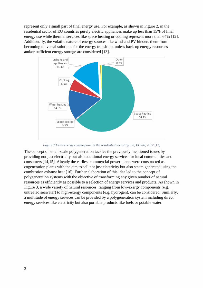
represent only a small part of final energy use. For example, as shown in Figure 2, in the
residential sector of EU countries purely electric appliances make up less than 15% of final
energy use while thermal services like space heating or cooling represent more than 64% [12].
Additionally, the volatile nature of energy sources like wind and PV hinders them from
becoming universal solutions for the energy transition, unless back-up energy resources
and/or sufficient energy storage are considered [13].
Figure 2 Final energy consumption in the residential sector by use, EU-28, 2017 [12]
The concept of small-scale polygeneration tackles the previously mentioned issues by
providing not just electricity but also additional energy services for local communities and
consumers [14,15]. Already the earliest commercial power plants were constructed as
cogeneration plants with the aim to sell not just electricity but also steam generated using the
combustion exhaust heat [16]. Further elaboration of this idea led to the concept of
polygeneration systems with the objective of transforming any given number of natural
resources as efficiently as possible to a selection of energy services and products. As shown in
Figure 3, a wide variety of natural resources, ranging from low-exergy components (e.g.
untreated seawater) to high-exergy components (e.g. hydrogen), can be considered. Similarly,
a multitude of energy services can be provided by a polygeneration system including direct
energy services like electricity but also portable products like fuels or potable water.

3
Figure 3 Polygeneration concept: multi-resource transformation to multi-products [17]
Although small-scale polygeneration systems can be fuelled with fossil fuels, such systems
would not represent a sustainable solution but only a less polluting form of energy service
provision. However, when using bio-resources instead, the concept of small-scale biomass-
based polygeneration (SBP) systems can distinguish itself from conventional energy systems
with various favourable characteristics:
High Efficiency [18]: The major objective of the polygeneration concept is to
capitalize on the primary energy resource as efficiently as possible. By providing
several energy services in close proximity to the final consumer, well-designed
polygeneration systems reach generally much higher overall energetic efficiencies
than conventional, centralized systems.
Renewable [19,20]: SBP systems can represent a renewable source of energy
provision, but only when supplied with biomass resources harvested under sustainable
management regimes. Over a certain life cycle, the biomass will regrow and absorb
the emissions caused by combustion within the polygeneration system. Hence the
system would operate carbon-neutrally. This is especially true for second and third
generation fuels, which are based on by-products from agriculture or forestry.
Flexibility [21]: Depending on the technologies incorporated, polygenration systems
can provide various services with great flexibility. This ability is especially desirable
on islands and in rural areas, where no alternative energy service providers may be
available.
Combinability [9,22]: Although SBP systems can serve demands with considerable
flexibility, they may be strictly limited by the biomass resources available or their
economic viability may be reduced due to high biomass prices. However, SBP
systems can be coupled easily with other energy resource technologies (e.g. solar),
other storage technologies (e.g. batteries), or other energy efficiency technologies (e.g.
heat pumps (HP)). This in turn, may not only lead to higher maximum capacities, but
also to a more stable and secure overall system with less risk of total breakdown.
Local Resources [20,23]: While in most regions the supply of fossil fuels depends on
external sources, for SBP systems locally grown and harvested biomass can be used.
In consequence, local supply chains as well as jobs can be created and the local energy
autonomy can be increased.
Resilience [24]: SBP systems can increase grid resilience not just by lowering the
dependence of one consumer structure on the grid but also by possibly providing

4
energy services to the entire network. The SBP system could turn the final consumer
to a combination of consumer and producer, often referred to as prosumer [25].
The many advantages show clearly that SBP systems have potential to play an important role
in the 21st century energy transition. However, there are also certain drawbacks inherent to the
concept of SBP. Firstly, due to their individual nature and the necessity to adjust each system
to the consumer’s demand, the design of polygeneration systems is immensely complex [19].
From this complexity stems also uncertainty, as several technologies have to work together
within uniquely designed systems, which may lead to unforeseen technical issues. This does
not just slow down the technical conception of SBP systems, but also complicates the
financing processes as it requires more time to convince investors. Additionally, once the
system has been constructed skilled technicians are required for secure maintenance and
operation. Secondly, although biomass can be collected to a certain degree in almost every
habitable region, it often may still not be enough to fulfil energy demands even with the most
efficient polygeneration design. This is especially critical in urban areas or densely populated
islands [26]. Hence, just as with wind and solar technologies, SBP should not be regarded as a
universal solution for a more sustainable energy system. The questions arises, when and
where SBP systems can reach their full potential and outperform not just conventional but
also new alternative energy technologies.
Within the greater context of the energy transition, there are several other technologies
competing with the concept of SBP, ranging from micro-scale solar PV systems to large-scale
energy network management technologies. Although many of these technologies are
compatible with SBP systems, they may be favoured by investors without considering
polygeneration due to possible smaller capital cost or simpler technical implementation.
Additionally, energy-related technologies are advancing at a rapid pace transforming
economic markets, politics, and societal structures [27]. As the SBP concept consists of
various technologies, the concept itself is also changing dynamically with new engineering
and design ideas appearing constantly. This further increases uncertainty and calls for a
cohesive overview of available technologies and concepts in order to allow scientists,
engineers, investors, and policy makers to make the right decisions.
Even if the choice of technologies to be considered has been narrowed down, the necessary
sizing of system components is crucial for technical and economic performance. To answer
this question, firstly, thorough analyses of the desired services and demands as well as of the
available local resources are necessary [28]. Based on these analyses, several techniques and
tools to engineer a suitable SBP systems can be used ranging from experimental trial-and-
error approaches to complex optimization algorithms [29,30]. However, some of these
techniques may not be suitable for brand-new polygeneration systems that have never been
conceived before. This implies that it may be necessary to develop further design techniques
and computational tools for SBP system engineering in order to expand their potential
application and increase precision of their techno-economic analyses.
1.1. Research questions
This thesis aims to respond to some of the previously raised issues and challenges concerning
the concept of SBP systems. To this purpose, several studies on various aspects of SBP

5
systems have been conducted, which in their compilation answer or at least reveal insights to
several unresolved questions. The general questions guiding this thesis are the following:
1. Where and how can SBP systems be an economically feasible alternative to
currently established energy systems?
2. How do these SBP systems perform compared to other energy systems in terms of
energetic and environmental benefits?
Related to the first question, the currently used energy system will be specified as the
reference system for each study. In most cases, the reference energy system is a conventional
fossil-fuel based, single generation system. In context of these general research questions,
several more specific questions arise, which were the focus of one or several of the papers
published during the PhD project. Table 1 lists these questions and relates each questions to
the corresponding publication.
Table 1 List of specific research questions answered in the thesis
What are suitable parameters to analyse the energetic, environmental,
and economic (3E) performance of SBP systems and to compare such
systems to conventional ones?
PAPER I
Which technologies are currently used in SBP systems? Which
technologies are to be expected in the near future?
PAPER I
What are optimal methods to design and operate SBP system? PAPER II -
PAPER V
How do SBP systems interact with alternative technologies PAPER III & IV
Hence, the general objectives of this work are to summarize all current knowledge on SBP,
highlight undiscovered research paths, and expand the knowledge on SBP systems within the
greater context of the 21st century energy transition. By answering above questions, this study
does not just advance the academic knowledge on SBP systems, but does also facilitate the
design of SBP systems for engineers and technicians, while highlighting distinctive beneficial
as well as unfavourable features.
1.2. Technological scope of the study
While the concept of polygeneration is not only gaining increasing interest amongst scientists
and engineers, it also describes a plethora of combinable technologies. In consequence, the
amount of literature and studies on systems, which would fit the broader definition of
polygeneration systems, exceeds the reasonable framework of a PhD thesis. Hence, it is
necessary to limit the scope of this study and to locate its importance within the field of
energy technologies. For this thesis, the following technological scope on the studied
polygeneration systems has been set:
Small-scale: All studied systems are small-scale energy systems, which is defined
here as systems with less than 1 MW rated electricity output [31]. Exemplary client
structures for which these SBP systems would be suitable are supermarkets,
hospitals, schools, office buildings, but also small villages, neighbourhoods, and/or
islands.
Biomass-based: The concept of polygeneration can be and is frequently based on
the combustion of fossil fuels. However, considering that this thesis is put into the
greater framework of the 21st century energy transition, the focus has been laid on
6
sustainable energy resources. Amongst renewable energy sources (RES), biomass is
just one of many resources, but it is arguably one of the most universally applicable
candidates for renewable energy-based, small-scale polygeneration systems. For
example, the rapidly growing wind and PV technologies are not generating heat at
high enough temperatures for most polygeneration concepts, while they are also
suffering from high intermittency [32]. On the other hand, geothermal energy might
generate heat at sufficiently high temperatures, but is too locally limited to be
considered a globally applicable solution [33]. Using solar-thermal energy collectors
for small-scale electricity and heat generation seems to be a promising solutions,
especially in conjunction with organic Rankine cycle (ORC) and Stirling engines.
However, so far only few of these system concepts are market ready as reliability
and maintenance have still to be improved [34]. Hence one of the great advantages of
biomass is that it can be produced, harvested, stored, and used as a fuel in most
habitable regions making it a flexible alternative to fossil fuels [35]. However, there
are also many cases where biomass is in disfavour compared to other technologies,
especially in regions with limited or no biomass growth (e.g. arid regions, tundra
regions, and regions suffering from excessive deforestation). Hence, biomass is also
not a universal solution, but is in the majority of cases a very suitable candidate for
renewable energy polygeneration systems.
Island-based / Autonomy: Especially for island-based and rural systems in
developing countries, a connection to a larger electric grid would imply infeasible
connections costs. However, even for systems studied in urban locations with good
access to a large electric grid, entirely autonomous operation with no electricity
served by the grid was studied for all conceived systems. This mode of operation is
generally referred to as island-mode [36,37] and the entire thesis concentrates on
such island-based systems.
CCHP and water purification: The thesis concentrates on advanced small-scale
polygeneration systems beyond the concept of combined heat and power (CHP).
Hence, heat recovery is essential in all studied systems, but is always followed by
another conversion process, more specifically either heat-driven cooling or water
purification to increase the number of energy services provided minimal increase on
electricity demand. In some cases, both electricity- and thermal-driven cooling
technologies are considered and their collaboration is investigated. While these two
aforementioned conversion processes already imply the knowledge of an ample set
of technologies, this definition excludes various other fields of energy technologies,
most notably biofuel generation. There are two major reasons for excluding the
generation of biofuels from the focus of this study. Firstly, the energy systems are
designed to satisfy the demand of a set local structure, hence there is no need to
export any fuels. Secondly, the generation of high quality fuels at the small-scale
level would rarely be an economically reasonable solution.
Solar-power enhanced: Despite of the great advantage of biomass as being a
storable energy resource, it is also limited in its biomass production capacity of the
surroundings. Hence, for many systems it is necessary to enhance the SBP system
with an additional energy source. This reduces dependence on one single energy
source by forming a hybrid energy system. In all studied systems, PV power has
been considered as a flexible and easily scalable additional RES.
Storage technologies: In relation to additional solar power technologies, in many
studied systems other forms of energy storage apart from biomass have been
considered in order to maximise the utilization of the biomass resources. Hence, not
just hybrid energy sources but also hybrid energy storage systems (HESS) have been

7
designed, specifically batteries, biogas storage domes, and water tanks for heat and
cooling storage. Such HESS may lead to greater system flexibility, longer lifetimes
and better economic performance [38].
By-products: Although the generation of electric and thermal energy services are
the main technical objectives of each system, in some studies additional bio-
chemical by-products and their greater socio-economic importance are considered. A
typical by-product for systems based on gasification would be charcoal, while for
systems based on anaerobic digestions a typical by-product would be bio-slurry.
1.3. Limitations
Apart from the limitations determined by the technological scope of the study as outlaid in
Chapter 1.2, there are also multiple methodological limitations to be acknowledged for this
thesis. These limitations have direct impact on how this thesis addresses the research
questions raised in 1.1:
Data quality: All results of the presented studies are based on data gathered from
external scientific, commercial, and governmental sources. All values and all sources
obtained from these sources have been examined, chosen, and referenced with great
care. Nevertheless, many implicit assumptions were inevitably made. For example,
data from a few years ago or from specific regions may no longer represent current
realities, especially for economic variables for rapidly developing markets.
Technical system perspective vs. political environment: All systems have been
investigated and designed from the perspectives of the polygeneration system owner
and/or operator. Even if the data would be 100% precise for a given moment and a
given location, it still remains highly influenced by circumstances outside of the
control sphere of the technical system. Unforeseeable changes in political frameworks
could quickly reduce the accuracy of the economic results. The political environment
influences economic input variables (e.g. biomass prices) as well as output variables
(e.g. electricity sales price). This dependence on political circumstances also affects
directly the environmental analysis of the studied systems, especially the sustainability
of the provided biomass. Although the biomass provision partners should be chosen
with due diligence, the administrative and political structures behind the biomass
provider are primarily responsible for upholding the legal standards of sustainability-
related regulations.
Computational limitations: For all presented model studies, a brute force
optimization approach has been chosen, wherein several size iterations for various
components of a proposed polygeneration system are simulated. Although such a
brute-force approach may find the best solution given the provided search space and
search steps, it is also the most exhaustive method and hence requires the longest
computation time [39]. In order to reduce computation time, the search steps can be
enlarged (i.e. consider larger differences between considered component sizes) but this
would lead to less precise results.
Sample size for trend analysis: Based on the published studies presented in chapters
3 and 4, some trends are eventually identified and discussed in Chapter 5. It must be
noted that the identification of these trends is based on a very small number of studies
and can therefore not be considered as scientific proof but instead should be regarded
as anticipatory indications.

8
Some of these limitations and their implications for this as well as for future studies are
discussed in more detail in Chapter 5 after the presentation of the different publications of
which this thesis is composed of.
1.4. Structure of the thesis
As mentioned in Chapter 1.2, this thesis is based on several published or to-be-published
scientific papers. Hence this thesis aims to collect and summarize the findings of all papers
presenting them in a coherent and concise way. To this purpose the thesis is structured as
follows:
1. In the introduction of Chapter 1, the motivation and the objectives are presented. In
order to not exceed the framework of this thesis, some technological limits have been
set for the scope of the study. In Chapter 1.3, the major methodological limitations of
this thesis are defined.
2. In Chapter 2 the methodological frameworks used for each study and for the entire
thesis are presented. The selected computational tools are presented and briefly
evaluated. Some key formulae and parameters are given and defined.
3. The state of the art on SBP is presented in Chapter 3. This chapter starts by putting the
thesis into the general context of biomass and distributed energy systems. Then,
specific studies on the SBP concept are presented with a special focus being laid on
studies of island-based SBP systems and the general modelling approaches for the
design of SBP systems. Finally, the contributions of each publication to the state of art
are summarized at the end of Chapter 3.
4. In Chapter 4, the various studies on SBP systems published during the PhD project are
described. For each study, the layout of the studied polygeneration system and a short
presentation of the methodological approach used for the techno-economic analysis of
the given system are presented. Chapter 4.1 starts with a techno-economic analysis of
a biomass-based CCHP system for a hotel complex on the Andaman Islands
comparing it to a CHP and two separate production systems. In Chapter 4.2, a biogas-
based SBP system for a rural community in Bolivia is described, where two different
storage technologies allow for higher flexibility and efficiency. Finally, a response to
the question on how small-scale CCHP systems can compete or collaborate with HP is
given by two studies presented in Chapters 4.3 and 4.4. The first study of this sub-
chapter puts a focus on the techno-economic performance of a combined CCHP/HP
system for various climate scenarios, while the second study investigates the exergetic
performance of such a system.
5. In Chapter 5, the findings of the studies are then synthesized critically discussed to
obtain a coherent picture of the relevance of this thesis for the field.
6. Finally in Chapter 6, the findings of the thesis are summarized and conclusions are
drawn. An outlook for future studies and future developments of SBP is given.

9
2. Methodology
In this chapter, the overlying methodology for the development of the entire thesis as well as
the applied software tools are presented. Additionally, a general methodologic framework
used in all modelling studies is presented, albeit it should be noted that the specific
methodologies used in each study differ from each other.
2.1. Thesis methodology
To answer the questions raised in Chapter 1.1, a methodological framework has been
developed, which is shown in Figure 4. The thesis can be separated in three interconnected
work packages:
1. Literature study: The thesis is based upon a thorough review of available scientific,
technical, and commercial literature. For this, various search tools have been used
including amongst others: digital websites, digital and physical literature works stored
in university libraries, and digital reference management software. All published
papers contain a literature review corresponding to their specific topic, but Paper I
surpasses the other papers by presenting a much larger breadth of literature and by
analysing the general patterns within the field. However, Paper I is limited to small-
scale, biomass-based combined cooling, heating, and power (CCHP) systems and does
not incorporate alternative polygeneration technologies. Furthermore, Paper I has been
published during the mid-phase of the PhD study, but the processes of scanning,
summarising, and structuring literature have never been halted. Therefore, an updated
literature review on SBP systems is presented in Chapter 2.
2. Techno-economic models and case studies: In this work package of the PhD project,
various techno-economic studies on different polygeneration systems in different
social and geographical areas were conducted. In each study, polygeneration systems
were designed with the aim to optimally fulfil the demands of selected localities given
the respective limitations of the local environments. To this purpose, different design
and optimization strategies were employed and are presented in Papers II-IV.
3. Synthesis: By analysing and synthesizing not only the individual results but also the
compound of the studies of the previous two work packages, the general research
questions of Chapter 1.1 are answered. As the thesis incorporates this synthesis, it
corresponds directly to these questions.

10
Figure 4 Methodological framework of this study
This study is based fully on computational work ranging from system design over model
simulation to optimization algorithms. Nonetheless, in all studies the demand analyses are
based on measured real life demand data, while the crucial components of each model are
based on technical and scientific data. Three mentionable software tools have been used for
simulating the polygeneration systems:
1. Hybrid Optimization of Multiple Energy Resources (HOMER) [40]: HOMER has
been developed by the National Renewable Energy Laboratory (NREL) in the United
States as a software tool to facilitate micro- to small-scale energy system design. After
simulating the system performance of one predetermined system design with variable
component sizes, HOMER ranks each system according to its best economic
performance over the project lifetime. Compared to other software tools used in the
PhD studies, HOMER excels in ease-of-use but lacks the possibilities of in-depth
component design and control. HOMER has been used for Paper II and Paper III and
its operating logic is explained there in further detail.
2. TRNSYS [41]: TRNSYS is an open-architecture modelling software for high
complexity, transient energy system simulation developed by the University of
Wisconsin. TRNSYS comes with a vast set of pre-built components, which have been
programmed with the FORTRAN programming language. Compared to HOMER,
TRNSYS allows for much more complex system design including more physical and

11
chemical phenomena. However, TRNSYS is not an optimization software and hence
does not find the optimal economic solution of a system design. TRNSYS has been
used in Paper IV & Paper V.
3. MatLab [42]: MATLAB has been developed by the MathWorks company and is
currently one of the most popular programming languages in the field of engineering.
While it is a very versatile programming language, it is especially useful for numerical
problems and their visualizations. MATLAB has been used in combination with
HOMER to allow, amongst others, for a more complex system control strategy in
Paper III. Furthermore, a MATLAB environment has been created to allow for
economic optimization of highly complex energy systems modelled with TRNSYS, in
Paper IV and Paper V.
As HOMER has been developed specifically for the design of energy systems, the calculation
processes of the components and their interactions have been validated by various other
system modellers. However, in TRNSYS a range of components can be connected in more
diverse ways, which can result in incorrect or illogical connections. MATLAB as a
programming language, allows for even more freedom in developing the model based on
particular software, which only elevates the risk of programming illogical or simply erroneous
component behaviour and relationships. Therefore, different validation procedures have been
used in order to test the developed TRSNYS and MATLAB models. These validation
procedures are:
Firstly, boundary value analysis with extreme values has been used, where the model
is fed with extreme input values and its outputs are scrutinized. In case the expected
model output differs from the output calculated by the model, the model has to be
revised for possible errors [43].
Secondly, in a cross-validation analysis the developed models have been fed with
input data from other studies and the outputs of the model have been compared with
those of the previous studies. In some case, the models have then been extended with
sub-models of various new components to allow its application for new
polygeneration systems.
Thirdly, sensitivity analyses have been conducted, where the impact of key input
variables on the entire system performance are analysed.
Fourthly, a white-box testing approach has been chosen for all models, where each
component is tested with various input values but also by considering the internal
logic of the component model [43].
2.2. General methodology of the modelling studies
For all modelling studies, the primary optimization objective of the developed models is to
reduce the project lifetime costs of the proposed SBP system. In all studies, the project
lifetime costs are expressed with the variable net present cost (NPC), which is calculated as
follows:
NPC = ∑Rt
(1 + i)t
n
t=0
=∑∑CCj + RCj + OMj + FCj − SRj − ESj
(1 + i)t
j
j =1
n
t=0
(1)

12
where Rt are the cashflows for year t, i is the real discount rate and n represents the project
lifetime. For each component j, Rt is composed of all capital costs CCj, replacement costs RCj,
costs and revenues for operation & maintenance OMj, fuel costs FCj, salvage revenues SRj,
and energy service sales ESj. The energy service sales can be any additional service generated
by the system that is not supplied directly to the client but sold to external sources. Examples
for energy service sales would be excess electricity, excess potable water, and excess biogas.
The mathematical formulation of the optimization can hence be expressed as:
min(NPC) ,Ecs ≤ Ecs,max
(2)
where Ecsis the annual capacity shortage of the system size iteration and Ecs,max is the
maximum allowed annual capacity shortage for the system to be considered viable.
The general methodological approach for the design and evaluation of the models developed
for the proposed polygeneration system is shown in Figure 5. The modelling approach can be
divided into three subsequent sub-processes:
A demand analysis phase, where the electric and thermal demand behaviour of the end
client are determined and analysed based on technical, site-specific, and economic
data.
The model creation phase is initiated starting with the SBP system design, where
technologies suitable to satisfy the energy service demands are selected and their
layout is determined. For the designed system, a model is devised and validated by
comparing it to other models and/or by conducting various input/output tests. The
model is then executed for the chosen case study settings and for all considered
iterations using a brute-force search approach [39]. For each iteration, the technical
outputs are stored and an economic model calculates the corresponding economic
performances.
In the final result analysis phase, the data is structured and visualized in order to
facilitate the discussion and conclusions drawn from the results.
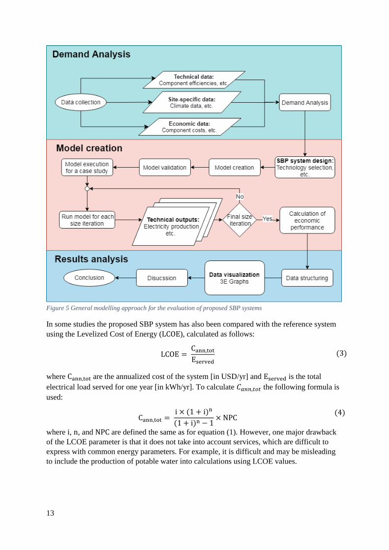
13
Figure 5 General modelling approach for the evaluation of proposed SBP systems
In some studies the proposed SBP system has also been compared with the reference system
using the Levelized Cost of Energy (LCOE), calculated as follows:
LCOE = Cann,totEserved
(3)
where Cann,tot are the annualized cost of the system [in USD/yr] and Eserved is the total
electrical load served for one year [in kWh/yr]. To calculate 𝐶𝑎𝑛𝑛,𝑡𝑜𝑡 the following formula is
used:
Cann,tot = i × (1 + i)n
(1 + i)n − 1× NPC
(4)
where i, n, and NPC are defined the same as for equation (1). However, one major drawback
of the LCOE parameter is that it does not take into account services, which are difficult to
express with common energy parameters. For example, it is difficult and may be misleading
to include the production of potable water into calculations using LCOE values.
14
3. Context and state of the art
The major benefits of SBP systems have been listed in Chapter 1. These benefits have made
SBP systems an interesting subject for engineers as well as scientists. Hence, in combination
with the versatile nature of SBP systems, a multitude of studies on the state of the art of the
subject is available. In this chapter a review on the state of the art is presented with a focus on
a selected range of technologies and their applications based on the scope defined in Chapter
1.2. Firstly, a general overview on the use of biomass for electricity generation and on
distributed energy systems is given in order to locate the thesis within the greater context of
the 21st century energy transition. Secondly, a comprehensive review of literature on SBP
systems is presented and commonly chosen modelling approaches for SBP systems are
outlined. This review summarizes literature on all types of polygeneration systems, but island-
based SBP systems and/or SBP systems operating in island-mode will be highlighted. At the
end of this chapter, the contributions of each paper to the state of the art are presented in a
summarized form.
It should be noted that Paper I already represents a thorough literature review on small-scale,
biomass-based CCHP systems. Thus, studies that have been summarized in detail in Paper I
are not mentioned in such detail in this review unless it supports the greater argument of the
thesis.
3.1. The context of biomass and distributed energy systems
In order to satisfy the world’s rising demand for energy while simultaneously to reduce the
emissions of GHG, the conception and deployment of more efficient and less polluting energy
systems are necessary [44]. While state-of-the-art centralized gas-fired power plants can
generate electricity with high efficiencies of up to 61%, the average electric efficiency of
thermal power plants employed worldwide is only 41% for gas and 34% for coal [45]. In most
cases none of the exhaust heat is recovered but instead given off to the environment, already
during the electricity generation phase in the power plant high losses occur. Additionally, due
to long transmissions and distribution grids further losses occur until the electricity reaches
the final end consumer. For the global average, electricity transport contributes up to 12% of
the total electricity losses, but makes up up to 30% of the costs of the delivered electricity
[45,46].
By harnessing locally available energy resources to supply energy services in close proximity
to the final user, distributed and decentralized energy systems aim to avoid these losses. A list
of advantages and disadvantages of decentralized energy systems is shown in Table 2.
Arguably, the advantages outweigh the disadvantages, but high obstacles like the increased
complexity not just of engineering but also of financing distributed energy systems hamper
the installation of such systems.

15
Table 2 Advantages and disadvantages of distributed energy systems vs. centralized systems
Advantages Disadvantages
Much lower electricity transmission
losses [30]
Reduced costs for transmission
infrastructure due to lower installation,
operation, and maintenance requirements
[53]
Locally placed CHP means heat can be
used directly without any need for heat
transmission infrastructure, which in turn
raises efficiencies [53]
The quick start-up capabilities of smaller
systems increase grid resilience and
flexibility [53]
Modular financial structures allow for
lower capital costs for individual
stakeholders [53]
Higher suitability towards locally
available RES [54]
Lower GHG emissions due to higher
efficiencies and application of more RES
[30,53]
More control equipment necessary as
each plant requires its own control [53]
Higher complexity and more difficulty to
synchronize with larger grid systems [53]
Higher risk of local hazard (especially
worrisome for urban areas) [53]
Usually, lower system electric
efficiencies despite of the higher system
energy efficiencies [38]
As indicated in Table 2, distributed energy systems can be used with various RES, of which
each source has its individual benefits and drawbacks. Although wind and solar technologies
are booming worldwide [47], their weather- and climate-dependent nature impedes
considering them as an universal solution [48]. Other RES like hydro or geothermal may
serve loads with greater continuity and controllability, but are limited to specific geographic
locations [32,33]. Thus, when aiming for providing not just electricity but also other energy
services using small-scale CHP or other polygeneration systems, biomass seems to be the
most promising energy source for several reasons [49]: biomass-based systems can be
installed and operated with considerable flexibility [50], biomass can be obtained as a waste
product at low and stable costs [51], and biomass can be stored in solid, gaseous, and liquid
form [52].
When considering the final energy consumption, biomass-based solutions still represent the
major energy source in the EU as shown in Figure 6. However, most of this biomass
consumption is destined for heating either directly at the end client’s structure or indirectly
via district heating grids. Only 13.4% of the consumed biomass are used for electricity
production and only 12% are used for biofuel generation pointing towards an immense
upgrading potential for polygeneration systems of any kind. Within the EU, bioelectricity has
experienced astonishing growth rates of 160% over the period from 2005 to 2016 [53] and
bioenergy as part of a larger bio-economy is projected to play a key role in the future energy
transition [54].
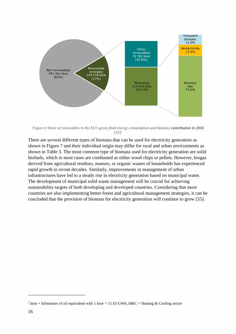
16
Figure 6 Share of renewables in the EU's gross final energy consumption and biomass contribution in 2016
[53]1
There are several different types of biomass that can be used for electricity generation as
shown in Figure 7 and their individual origin may differ for rural and urban environments as
shown in Table 3. The most common type of biomass used for electricity generation are solid
biofuels, which in most cases are combusted as either wood chips or pellets. However, biogas
derived from agricultural residues, manure, or organic wastes of households has experienced
rapid growth in recent decades. Similarly, improvements in management of urban
infrastructures have led to a steady rise in electricity generation based on municipal waste.
The development of municipal solid waste management will be crucial for achieving
sustainability targets of both developing and developed countries. Considering that more
countries are also implementing better forest and agricultural management strategies, it can be
concluded that the provision of biomass for electricity generation will continue to grow [55].
1 ktoe = kilotonnes of oil equivalent with 1 ktoe = 11.63 GWh, H&C = Heating & Cooling sector

17
Table 3 Rural and urban biomass feedstock sources [56,57]
Rural Urban
Forest residues and wood waste. Urban wood waste (packing crates, pallets,
etc.)
Agricultural residues (corn stover, wheat
stalk, etc.)
Wastewater and sewage biogas
Energy crops (grasses or trees) Landfill gas
Biogas from livestock Municipal solid waste and food processing
residues
Figure 7 Global electricity generation from different biomass sources [55]
The complex nature of biomass and the many possible conversion technologies complicate
any complete analysis of its socio-economic and environmental impacts [58]. However,
different types of biofuels can be distinguished according to their origin [59]:
1. First generation biofuels are directly derived from food crops (e.g. rapeseed). These
biofuels are heavily criticised not just by many scientists but also by the public, as
many negative impacts on food security and biodiversity paired with questionable
benefits for GHG emission reductions have been reported [60].
2. Second generation biofuels are based on residues from agriculture and silviculture.
They are sometimes considered as a sustainable response to the criticism of first
generation biofuels [60] and have experienced considerable growth since the start of
the 21st century,
3. Third generation biofuels are based on algae. Such biofuels are still in the
development phase with no constructed large-scale facilities existing [61].

18
Currently, second generation bio-fuels seem to be the favourite choice for CHP purposes in
the bioenergy sector [58]. Nevertheless, even when harvested following sustainable criteria,
second generation biomass requires management of considerable land area and hence
inevitably involves an infringement of humanity into nature. Two advanced conversion routes
can be chosen for small-scale second generation biomass conversion:
1. The thermo-chemical conversion route, where thermal energy is supplied to biomass
in a low oxygen environment. The thermo-chemical conversion route can be separated
into the following processes:
a. Firstly, in a drying phase the heating value of the biomass is increased by
simply removing humidity.
b. Secondly, in the pyrolysis phase larger biomass molecules are cracked down to
smaller ones with the main product being a mixture of various liquid chemical
compounds [62].
c. Thirdly, in the gasification phase the molecules are further broken down with
the main product being a mixture of various gases called synthesis gas or
syngas [63]. Typical gas composition values for small-scale downdraft
gasifiers are shown in Table 4.
2. The bio-chemical conversion route, where micro-organisms break down biomass into
smaller molecules. The bio-chemical conversion route can also be separated into
different categories:
a. Fermentation, where biomass crops are first converted to sugars and then
fermented to alcohols. This process is used in various countries in large-scale
facilities [64].
b. Anaerobic digestion, where bacteria convert biomass into biogas, which results
in a mixture of approximately 60% methane and 40% carbon dioxide [65].
The two most commonly chosen small-scale conversion technologies for second generation
biofuels are gasification for woody biomass and anaerobic digestion for agricultural residues
[19].
Table 4 Typical syngas composition from commercial wood for downdraft gasifiers [66]
Composition 𝑥𝐶𝑂 𝑥𝐶𝑂2 𝑥𝐻2 𝑥𝐶𝐻4 𝑥𝑁2 Syngas LHV
[MJ/Nm]
[% vol] 17-22 9-15 12-20 2-3 50-54 5.0-5.9
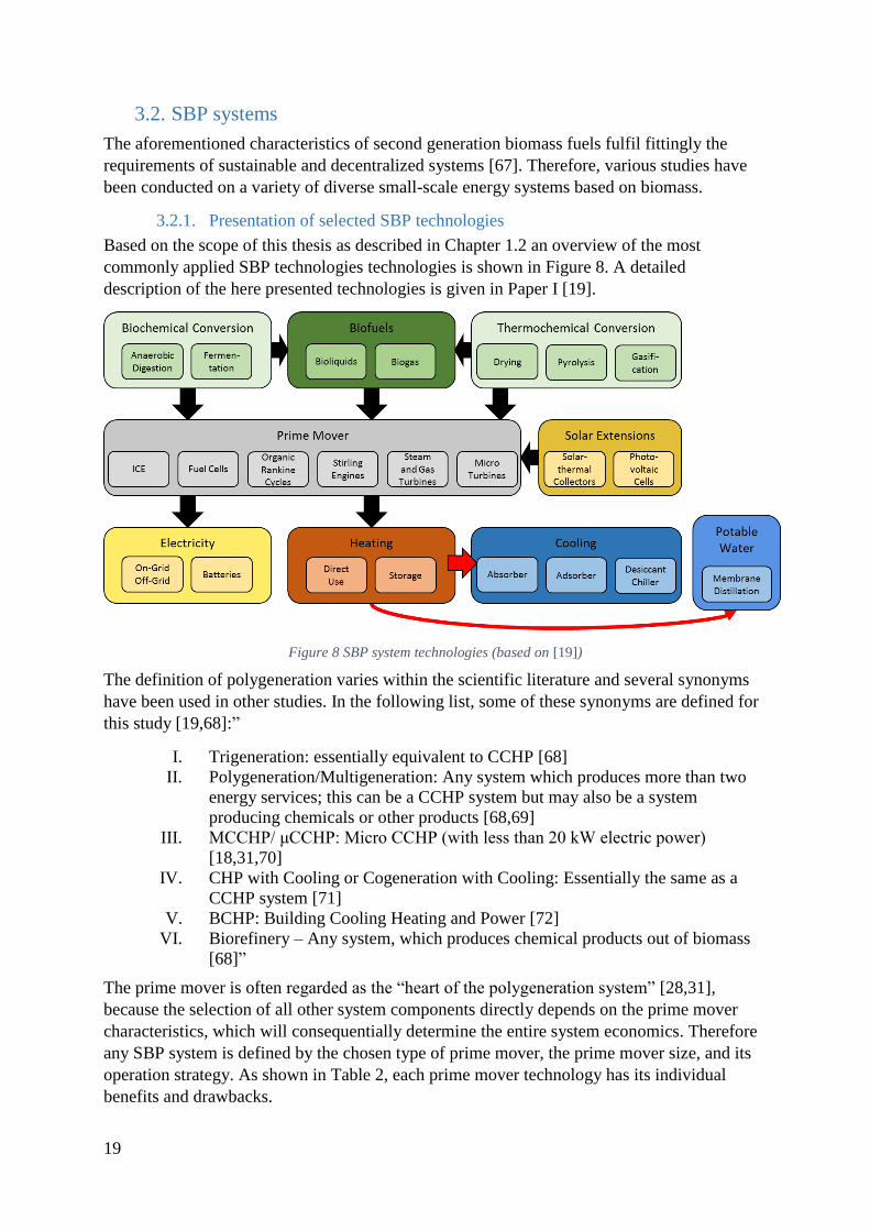
19
3.2. SBP systems
The aforementioned characteristics of second generation biomass fuels fulfil fittingly the
requirements of sustainable and decentralized systems [67]. Therefore, various studies have
been conducted on a variety of diverse small-scale energy systems based on biomass.
3.2.1. Presentation of selected SBP technologies
Based on the scope of this thesis as described in Chapter 1.2 an overview of the most
commonly applied SBP technologies technologies is shown in Figure 8. A detailed
description of the here presented technologies is given in Paper I [19].
Figure 8 SBP system technologies (based on [19])
The definition of polygeneration varies within the scientific literature and several synonyms
have been used in other studies. In the following list, some of these synonyms are defined for
this study [19,68]:”
I. Trigeneration: essentially equivalent to CCHP [68]
II. Polygeneration/Multigeneration: Any system which produces more than two
energy services; this can be a CCHP system but may also be a system
producing chemicals or other products [68,69]
III. MCCHP/ μCCHP: Micro CCHP (with less than 20 kW electric power)
[18,31,70]
IV. CHP with Cooling or Cogeneration with Cooling: Essentially the same as a
CCHP system [71]
V. BCHP: Building Cooling Heating and Power [72]
VI. Biorefinery – Any system, which produces chemical products out of biomass
[68]”
The prime mover is often regarded as the “heart of the polygeneration system” [28,31],
because the selection of all other system components directly depends on the prime mover
characteristics, which will consequentially determine the entire system economics. Therefore
any SBP system is defined by the chosen type of prime mover, the prime mover size, and its
operation strategy. As shown in Table 2, each prime mover technology has its individual
benefits and drawbacks.

20
Table 5 Assessment of Prime Movers for small-scale biomass-fired CCHP systems [19]
Prime Mover Internal
Combustion
Engines
Fuel
Cells
Stirling
Engines
Organic
Rankine
Cycles
Micro
Turbines
Size Up to
100 MW [73]
Up to 2 MW
[73]
Up to 150 kW [74] Up to 2 MW
[74]
Up to 1 MW
[31]
Advantages Very high
reliability (with
clean fuels)
[28,31]
Rapid start-up
[31]
Low investment
costs [31]
Excellent
partial load
performance
[73]
Very high
electric
efficiency
[15,31]
Low noise
[28]
Low
emissions
[15,31]
Can use low
quality fuels
due to external
combustion
[31,73,75]
Good partial
load
performance
[73,75,76]
Potentially
low
maintenance
requirements/
less moving
parts [31,77]
High thermal
efficiency [15]
Low emissions
[15,75]
Can run with
low grade heat
[76]
High reliability
[76,78]
Low
maintenance
costs [15,79]
Good partial
load behaviour
[78]
Low quality
fuels can be
used for
externally
driven units
[31]
Very few
moving parts
[31]
Very
compact
sizes [31]
High
temperature
exhaust [28]
Low
emissions
[28]
Disadvantag
es
Short
maintenance
intervals
[28,31]
Instability with
bio- and
syngas/ limited
fuel flexibility
[31,79,80]
High noise [28]
High NOx-
emissions
[15,31]
Using waste
heat difficult
[28]
Very high
investment
costs [15]
SOFCs have
long start-up
times [73]
Requires
very high
quality,
energy
intensive
fuels [31]
Low heat
recovery
[15]
Still high
investment
costs [31]
Low electric
efficiency
[15,75]
Technology
not fully
developed
[28,75]
Difficult to
control power
output [75]
Still high
investment costs
[15]
Low maximal
electric
efficiency [15]
Low heat
recovery for
low-grade heat
applications
[74]
Still high
investment
costs [31]
Difficult
Start-up
[15,31]
Delicate
mechanical
design [32]
Low electric
efficiency
[81]
Commonnes
s in reviewed
cases [19]
Most common
18/39
Rare
3/39
Rare
2/39
Common
12/39
Rare
4/39*
Assessment
of potential
Remains stable High [28] Very High [74] High [74] Very high
[31,82] *Including Steam & Gas turbines
A visual summary of a meta-data analysis of 41 small-scale, biomass-fired CCHP systems is
shown in Figure 4. Internal Combustion Engines (ICE) seem to be the most popular choice for
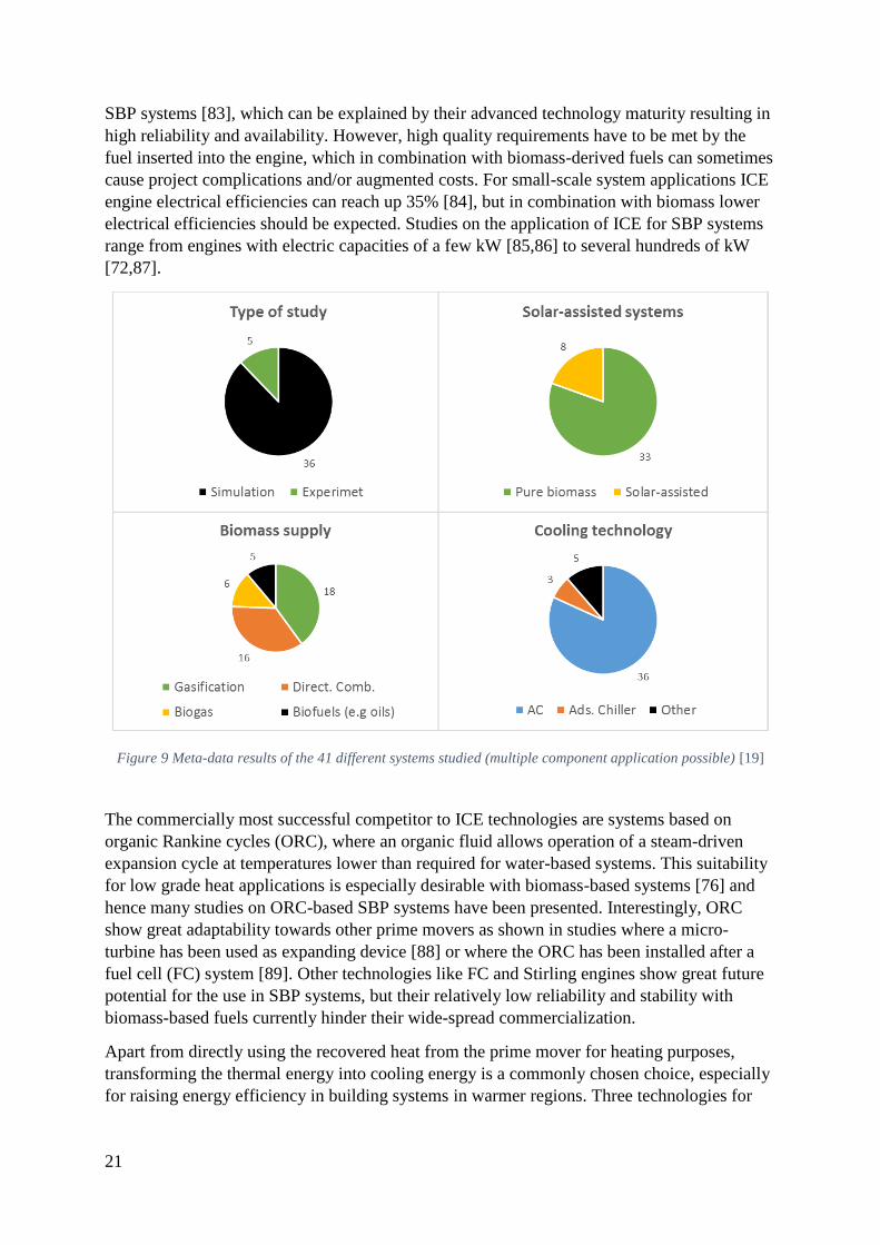
21
SBP systems [83], which can be explained by their advanced technology maturity resulting in
high reliability and availability. However, high quality requirements have to be met by the
fuel inserted into the engine, which in combination with biomass-derived fuels can sometimes
cause project complications and/or augmented costs. For small-scale system applications ICE
engine electrical efficiencies can reach up 35% [84], but in combination with biomass lower
electrical efficiencies should be expected. Studies on the application of ICE for SBP systems
range from engines with electric capacities of a few kW [85,86] to several hundreds of kW
[72,87].
Figure 9 Meta-data results of the 41 different systems studied (multiple component application possible) [19]
The commercially most successful competitor to ICE technologies are systems based on
organic Rankine cycles (ORC), where an organic fluid allows operation of a steam-driven
expansion cycle at temperatures lower than required for water-based systems. This suitability
for low grade heat applications is especially desirable with biomass-based systems [76] and
hence many studies on ORC-based SBP systems have been presented. Interestingly, ORC
show great adaptability towards other prime movers as shown in studies where a micro-
turbine has been used as expanding device [88] or where the ORC has been installed after a
fuel cell (FC) system [89]. Other technologies like FC and Stirling engines show great future
potential for the use in SBP systems, but their relatively low reliability and stability with
biomass-based fuels currently hinder their wide-spread commercialization.
Apart from directly using the recovered heat from the prime mover for heating purposes,
transforming the thermal energy into cooling energy is a commonly chosen choice, especially
for raising energy efficiency in building systems in warmer regions. Three technologies for

22
thermally-driven cooling have been commercialized and are occupying different parts of the
thermal-cooling market [90]:
Absorption chilling
Adsorption chilling
Desiccant chilling
The most common thermally-driven cooling technology is absorption chilling, where the heat
recovered from the prime mover is used to separate a working fluid from an absorption
mixture through evaporation. The working fluid is then cooled down in order to condense and
eventually led to an evaporator, where it absorbs heat at low pressure and hence cools down
its surroundings. Eventually, the working fluid is led back to the absorption mixture and is
reabsorbed. A simplified working scheme for an absorption refrigeration cycle is shown in
Figure 10.
Figure 10 Simplified process of an absorption refrigeration cycle (based on [91])
The recovered thermal exhaust heat from the prime mover could also be used for generating
potable water by using thermally-driven water purification technologies. For low-temperature
heat applications various types of membrane distillation (MD) technologies seem to be the
favourable option compared to pressure-driven technologies like reverse osmosis (RO), which
are more common for general applications. In a MD process vapour from a hot feed water
loop passes through a porous, hydrophobic membrane and is then condensed by a cooled
down receiver plate. Two exemplary configurations of MD unit configurations are shown in
Figure 11. The advantages of MD compared to competing technologies are lower energy
costs, lower operating temperatures, and lower space requirements [92].
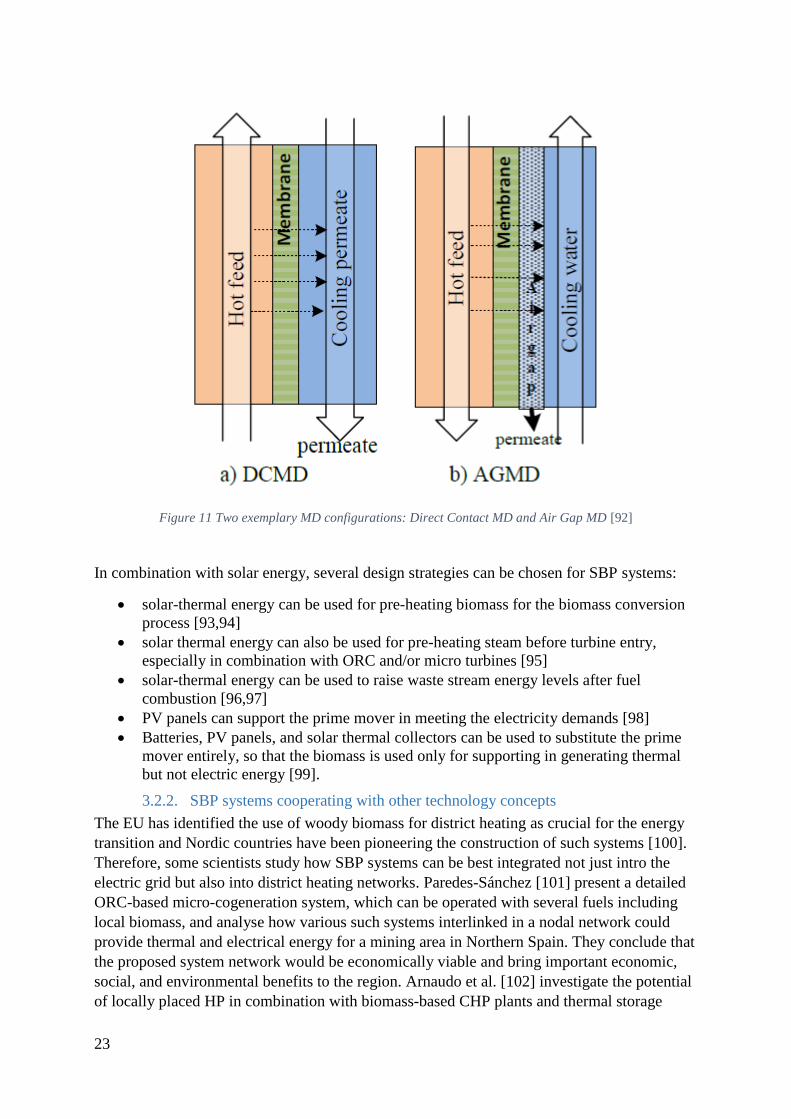
23
Figure 11 Two exemplary MD configurations: Direct Contact MD and Air Gap MD [92]
In combination with solar energy, several design strategies can be chosen for SBP systems:
solar-thermal energy can be used for pre-heating biomass for the biomass conversion
process [93,94]
solar thermal energy can also be used for pre-heating steam before turbine entry,
especially in combination with ORC and/or micro turbines [95]
solar-thermal energy can be used to raise waste stream energy levels after fuel
combustion [96,97]
PV panels can support the prime mover in meeting the electricity demands [98]
Batteries, PV panels, and solar thermal collectors can be used to substitute the prime
mover entirely, so that the biomass is used only for supporting in generating thermal
but not electric energy [99].
3.2.2. SBP systems cooperating with other technology concepts
The EU has identified the use of woody biomass for district heating as crucial for the energy
transition and Nordic countries have been pioneering the construction of such systems [100].
Therefore, some scientists study how SBP systems can be best integrated not just intro the
electric grid but also into district heating networks. Paredes-Sánchez [101] present a detailed
ORC-based micro-cogeneration system, which can be operated with several fuels including
local biomass, and analyse how various such systems interlinked in a nodal network could
provide thermal and electrical energy for a mining area in Northern Spain. They conclude that
the proposed system network would be economically viable and bring important economic,
social, and environmental benefits to the region. Arnaudo et al. [102] investigate the potential
of locally placed HP in combination with biomass-based CHP plants and thermal storage
24
strategies for a greater thermal network. When employing the locally sourced HP, significant
cost and emissions reductions can be obtained. This shows that the cooperation of SBP
systems and HP can lead to improved total system performance.
Some studies have also been conducted for the end-user level on the combination of
polygeneration systems and HPs. Mancarella [103] presents a general modelling approach on
how to optimally size components of a CHP/HP system by identifying key parameters for the
decision makers. He shows that the CHP/HP sizing but also the expected emission and fuel
reduction rely heavily on the heat-electricity demand ratio of the end client. A graphical
calculation tool for combining CHP and HP systems based on off-design operation conditions
is proposed by Lo Basso et al. [104], who highlight that the economic viability depends
heavily on the electricity price. Specifically for the coupling of CCHP systems with a ground-
sourced heat pump (GSHP) system, Zeng et al. [25] employed a multi-population genetic
algorithm, while Li et al. [105] used a quantum genetic algorithm for a similar system. In both
studies the proposed system show energetic and environmental performance improvements
compared to separated generation systems.
Even though the previously mentioned studies focus on optimization of combined CHP/HP or
CCHP/HP systems, all of them focus on fossil-fuelled systems and hence do not investigate
the economic as well as environmental impact of biomass-based fuels on such CCHP/HP
systems. A study taking this neglected factor into account could facilitate the design of
CCHP/HP systems and further promote the SBP concept.
Although the biomass used in SBP can be considered as a form of energy storage, the SBP
concept can be further enhanced with other energy storage technologies to create a Hybrid
Energy Storage System (HESS). Just as with polygeneration, the concept of HESS
encompasses numerous developed and developing technologies ranging from fast reacting
super-capacitors over all sorts of electro-chemical batteries to long-term storage technologies
like pumped hydropower plants. Commonly a “sprinter”-“marathon runner” combination is
used [106]:
The “sprinter” device serves primarily short-term load fluctuations, which requires
technologies with fast response times and high cycle lifetimes.
The “marathon runner” serves primarily long-term load demands and hence requires
technologies with low self-discharge rates and lower energy specific costs.
By decoupling the requirements for long-term energy storage and short-term power serving,
the total investment costs of the storage system can be decreased. Additionally, the storage
system efficiency can be increased, as the two technologies can be operated closer to their
optimal operation profiles. However, the optimal operation of both technologies will also
require sophisticated control strategies and mechanisms. Moreover, the reduction of short-
term strains on the “marathon runner” can also lead to increased lifetimes of the long-term
storage device [38]. A thorough overview of how storage technologies can be combined has
been presented by Bocklisch [38],while a review focusing specifically on HESS for microgrid
applications has been given by Hajiaghasi et al. [107]. Both reviews highlight the potential of
the HESS concept, especially in combination with RES, and both underline the complexity of
designing such HESS. However, neither of the authors considers biomass explicitly in their
reviews on HESS, but hydrogen is mentioned as a potentially biomass-derived fuel. There are
few studies considering biogas in combination with other storage technologies for RES

25
systems. Rad et al. [108] present various hybrid PV/wind turbine/biogas generator/FC
systems for on- and off-grid use in a rural settlement in Iran. They conclude that the most
cost-effective solution is a PV/wind turbine/biogas generator combination, while the FC
would not improve system economics. Although a detailed analysis on the biogas potential is
conducted, no specific details are presented on the biogas storage facilities and subsequent
storage strategies.
There are many similar studies considering biomass for hybrid-energy systems (e.g. [109–
111]), but none of these studies consider explicitly the storage control strategy of the HESS.
Hence there is a gap in the state of the art considering the optimal control strategy of biogas
and batteries for SBP systems.
3.2.3. Effects of climate variables on SBP systems
Some of the most recent studies on SBP systems consider not just how technological but also
how geographical aspects influence system performance. Depending on the geographical
region the energy service demands of the end client will vary greatly. Especially for CCHP
systems, more extreme climates seem to be favourable, because these regions demand more
cooling as well as heating from the energy service provider. For example, Mouaky et al. [112]
investigate how parabolic collectors can support the biomass conversion process for a 46 kWe
ORC-based system located in a semi-arid, rural region of Morocco. After expansion in the
ORC turbine, the remaining heat of the working fluid is used for water purification via a RO
unit and for heating up domestic hot water (DHW). The system would produce electricity,
fresh water, and DHW at relatively high cost compared to market costs. However, the remote
location of the studied system may justify such a high price discrepancy. The system
performance is also highly influenced by ambient temperatures and solar radiation.
In a study by Sigarchian et al. [113] the effects of various climate zones of Iran on the design
and performance of a CCHP system are investigated. Although different climate zones require
different sizing of the CCHP components, it could be shown that in all cases the CCHP
system shows great environmental and energetic performance. Yet only in the hottest climate
the CCHP system would lead to cost reductions, while in the other zones the CCHP systems
would be economically unfeasible due to too low cooling demands. In a similar study by
Ebrahimi et al. [114] a CCHP system is optimized for 5 different cities in Iran. They found
that fuel savings of up to 38% can be achieved depending on the region with high system
efficiencies of up to 85%. However, none of these studies consider the foreseeable impact of
climate change on the component performance and the system design of SBP systems.
The environmental climate does not just influence the SBP system component design but also
the system and component control strategies. Apart from the ambient climate, the load control
is influenced by other system components and by the demand characteristics of the end client.
In turn, control algorithms can reach significant complexity levels. The most common
strategies are:
Following Electric Load (FEL): The prime mover power output is set to always fulfil
the electric energy demand of the end client.
Following Thermal Load (FTL): The prime mover output is set to always fulfil the
thermal energy demand of the end client
However, many researchers propose hybrid control strategies using each of the previous or
entirely new control strategies depending on different decision criteria. Sigarchian et al. [115]
26
developed a modified base load control strategy, where the prime mover is operating
according to FEL, but has not to fulfil the electricity demand entirely and can hence be
downsized. Comparing the new control strategy to FEL and FTL using a case study for a
residential building in the temperate climate of Northern Italy, they conclude that each
strategy has its benefits and drawbacks; while the new control strategy requires the least
capital costs, FEL allows for the most energy autonomy while FTL shows the best
environmental performance. Li et al. [105] compared five different control strategies for a
fossil-fuelled CCHP/GSHP system in a hotel in China. They did not identify any significant
performance differences between FEL and FTL strategies, but stated that their strategy of
following maximum electric efficiency shows the best results for the case study. On the other
hand, in their study on the optimization of CCHP/GSHP systems Kang et al. [116] found
indications that FTL may be more suitable for extreme weather conditions, while FEL seems
to be better for mild climates.
Studying any given system for all climate zones and applying all developed control
mechanisms would be an overly exhaustive task. Therefore, suitable software and control
mechanisms for a given case study must be chosen carefully and based on scientific findings.
3.2.4. Specific examples of island-based polygeneration systems
The promotion of RES on islands has received increased interest in recent years, which results
in initiatives like the Global Renewable Energy Islands Network (GREIN) founded by the
International Renewable Energy Agency (IRENA) and supported by the United Nations
[117,118]. Several investigation groups and authors investigated the potential for renewable
energy systems on specific islands, island archipelagos and/or islands groups. Blechinger et
al. [119] provide an overview for nearly 1,800 islands with a population of up to 20 million
inhabitants collecting data on economic development, energy demand and respective fuel
costs. Their findings reveal that on all the islands in total 15 GW diesel-systems are operating
and that a potential for 7.5 GW PV systems and 14 GW wind systems exists, which could be
installed and produce electricity not just much more sustainably but even more cost-efficient.
Seizing this potential would imply a 50% reduction of fuel consumption and an electricity
cost reduction of nearly 0.10 USD/kWh could be accomplished when also considering battery
storage measures. Many studies underline also the necessities for energy storage on islands in
order to increase the share of RES [120,121].
Considering SBP systems on islands, Karellas et al. [122] presented a micro-scale ORC
system with a peak electricity output of 6 kW, which uses a VC chiller of ca. 10 kW cooling
capacity. By superheating the working fluid after the reactor with parabolic trough-collectors
the efficiency is further increased. Applying the system in a case study for the Greek island of
Milos, an payback period of 7 years was estimated for the worst-case scenario. Salehin et al.
[123] simulated a solar PV-biogas-diesel hybrid energy system for the island of Adorsho
Char, Bangladesh. The system consists of 7.2 kW solar PV panels, a 16 kW biogas generator,
a 9 kW Diesel generator and 12 batteries (1,900 Ah each). The simulations show that
electricity can be provided to the underdeveloped island with just 0.217 USD/kWh. A very
specific and very innovative example of a trigeneration system based on renewable energies
has been presented by Calise et al. [124]. They propose to use geothermal energy on the
volcanic island of Pantelleria in the Mediterranean Sea and support the system with
concentrating photovoltaic-thermal (PVT) collectors. By using multi-effect distillation, the
system can produce potable water and by using an absorption chiller (ABS), it can provide
27
cooling energy. After analysing the system performance economically, they conclude that
even without government funding, a payback period of less than 10 years will be achieved,
but that feed-in tariffs could substantially lower the payback period.
Although all the previously mentioned studies present energy systems for islands based on
RES, none of them analyse the technical and socio-economic aspects of a solar-assisted,
biomass-based SBP system. As both, solar energy and biomass may be locally available on
islands, such a SBP system could lead to significant emissions savings and cost reduction not
just for one individual system owner but for the entire island population.
3.2.5. SBP systems modelling
Many approaches to compute energy system models can be followed, which can be separated
into two categories: optimization and simulation models [22]. While optimization models try
to find the optimal solution of a decision criteria, simulation models try to replicate the
physics of a given system as close as possible. However, the lines between the two categories
are naturally blurry because each optimization model needs to simulate at least to a minimal
degree the physical laws of a given energy system. The techniques used in optimization
models can be separated into two categories again:
1. Mathematical programming including linear programming (LP), mixed-integer linear
programming (MILP), and mixed-integer non-linear programming (MILNP). Some
specific examples for small-scale energy system models are given by Bischi et al.
[125] using MILP for optimal sizing of CCHP systems and by Hemmati et al. [126]
using MILNP for the optimization of micro-grid RES systems.
2. Metaheuristic algorithms including genetic algorithm (GA), evolutionary algorithm
(EA), and particle swarm optimisation (PSO). Some specific examples for small-scale
polygeneration system models are given by Zeng et al. [25] using a multi-population
GA to optimise a CCHP/GSHP system, by Sigarchian et al. [113] optimizing a CCHP
system for various climates using PSO, and by Hajabdollahi et al. [113] using
evolutionary algorithms for CCHP plant optimization.
Numerous other examples of how both types of optimization techniques can be used for
polygeneration system modelling can be found in the literature. For a wider selection of
studies it is here referred to Mavromatidis et al. [22].
For simulation models, it is often more convenient to use established energy engineering
software, where individual components have already been programmed and validated by other
scientists and/or engineers. Exhaustive reviews have been presented by Sinha et al. [127] and
Lyden et al. [128] listing some of the most popular software tools. These are amongst others:
TRNSYS [41], HOMER [40], Hybrid2, RETScreen, iHoga, Modelica, and Aspen Plus. For
this thesis TRNSYS and HOMER have been used as explained in Chapter 2. Each energy
system simulation software has its benefits and drawbacks, which is why the selection of the
software has to be carried out prudently. However, most of these tools are merchandised by
commercial enterprises, which may limit the choice of the researcher.
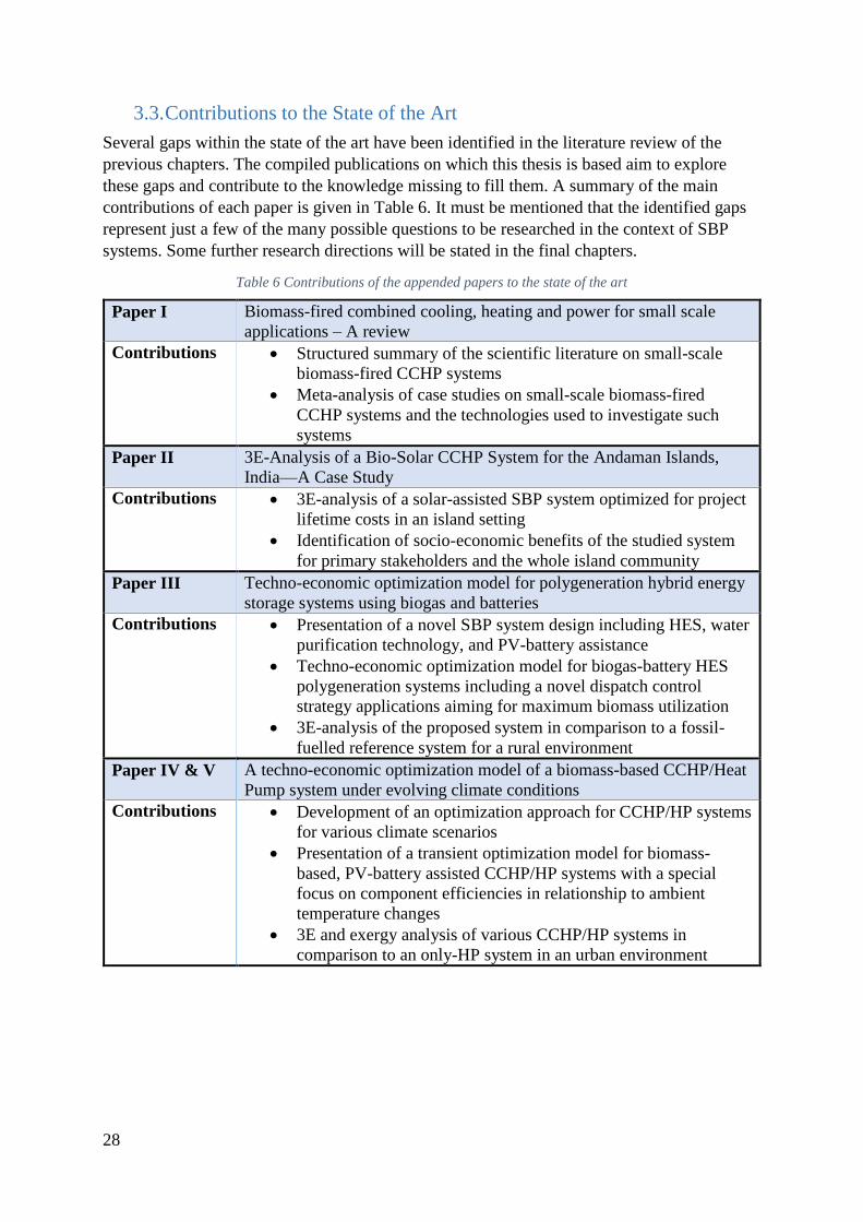
28
3.3. Contributions to the State of the Art
Several gaps within the state of the art have been identified in the literature review of the
previous chapters. The compiled publications on which this thesis is based aim to explore
these gaps and contribute to the knowledge missing to fill them. A summary of the main
contributions of each paper is given in Table 6. It must be mentioned that the identified gaps
represent just a few of the many possible questions to be researched in the context of SBP
systems. Some further research directions will be stated in the final chapters.
Table 6 Contributions of the appended papers to the state of the art
Paper I Biomass-fired combined cooling, heating and power for small scale
applications – A review
Contributions Structured summary of the scientific literature on small-scale
biomass-fired CCHP systems
Meta-analysis of case studies on small-scale biomass-fired
CCHP systems and the technologies used to investigate such
systems
Paper II 3E-Analysis of a Bio-Solar CCHP System for the Andaman Islands,
India—A Case Study
Contributions 3E-analysis of a solar-assisted SBP system optimized for project
lifetime costs in an island setting
Identification of socio-economic benefits of the studied system
for primary stakeholders and the whole island community
Paper III Techno-economic optimization model for polygeneration hybrid energy
storage systems using biogas and batteries
Contributions Presentation of a novel SBP system design including HES, water
purification technology, and PV-battery assistance
Techno-economic optimization model for biogas-battery HES
polygeneration systems including a novel dispatch control
strategy applications aiming for maximum biomass utilization
3E-analysis of the proposed system in comparison to a fossil-
fuelled reference system for a rural environment
Paper IV & V A techno-economic optimization model of a biomass-based CCHP/Heat
Pump system under evolving climate conditions
Contributions Development of an optimization approach for CCHP/HP systems
for various climate scenarios
Presentation of a transient optimization model for biomass-
based, PV-battery assisted CCHP/HP systems with a special
focus on component efficiencies in relationship to ambient
temperature changes
3E and exergy analysis of various CCHP/HP systems in
comparison to an only-HP system in an urban environment

29
4. SBP models and case studies
In this chapter, all publications compiled for this thesis will be briefly summarized and their
main findings will be recapitulated. For each paper, the methodology and a description of the
case study will be presented in order to explain how the main findings of each publication
have been derived. Finally, some concluding remarks on each publication and how they
impact the research on SBP will support the synthesis of the research topic.
4.1. Techno-economic optimization of small-scale, biomass-based CCHP
system for an island resort structure (Paper II)
In the following study the viability of various energy systems for a small hotel complex on
Neil Island, one of the Andaman Islands in the Bay of Bengal, has been analysed using the 3E
approach. The aim of the study was to identify the benefits and drawbacks of a small-scale,
biomass-based CCHP system with PV-battery assistance in comparison to separate production
of a diesel-fuelled reference system as well as to an only PV-assisted diesel system and a PV
assisted biomass-based system without polygeneration measures. Crucially, the study focused
not just on the techno-economic performance of the proposed energy systems, but also on the
greater socio-economic effects on the island and its inhabitants.
4.1.1. Case description and technical input
During the time of the study, the Andaman Islands were heavily dependent on petroleum
imports for their energy system with over 90% of the electricity generation having been
supplied by diesel generators [129]. In turn long and instable transport chains led to increased
energy prices and higher emissions, while especially on Neil Island frequent breakdowns of
the electric grid occurred. Therefore, the hotel owner has shown interest in renovating his 40
guest room hotel structure including a more self-sustaining, sustainable, and cost-effective
energy service provision system. The hotel is located at approximate latitude 11°59′ and
longitude 92°7′ receiving an average daily solar radiation of 4.72 kWh/(m2·day). Hence, the
conditions for PV panels have been considered as very satisfactory.
Based on building characteristics and occupant profiles, the electric demand profile of the
reference system has been calculated with the electric load for one entire year as being shown
in Figure 12. The thermal demand of the hotel rooms and the service installations have been
calculated based on minimum requirements as formulated in the ASHRAE (American Society
of Heating, Refrigerating and Air-Conditioning Engineers) standard [130]. The daily peak
electrical demand time starts at 18:00h and ends at 22:00h with no major alteration in the
curves for weekdays and weekends. During the high tourist season from November to March
the average demand is significantly higher than during the low tourist season from April to
October. Because this demand contains electricity for thermal as well as non-thermal services
and because the CCHP system provide parts of the thermal services using thermal instead of
electric energy, the electricity demand curve for purely electric service appliances will be
lower for the CCHP system.

30
Figure 12 Max. electric load for each hour of the year in blue and 30-day average in red [131]
After the system demand analysis, the following energy system layouts have been taken into
consideration for analysis:
Reference case 1: The hotel receives electricity from the grid from 00.00-18.00 and
operates a diesel engine from 18.00-24.00, which is when the grid most frequently
brakes down.
PV-Battery case 2: As above, but the system is now supported by PV panels and
batteries.
PV-Battery-Biomass case 3: As above, but the system uses a biomass downdraft
gasifier connected to a gas engine instead of a diesel engine.
PV-Battery-Biomass CCHP case 4: As above, but the system operates now entirely
off-grid and the exhaust heat from the gas engine is recovered and used for water
heating and for cooling via an ABS. A biomass boiler has been added for thermal
energy provision whenever the engine is not running or not providing sufficient heat.
The CCHP system layout is shown in Figure 13.
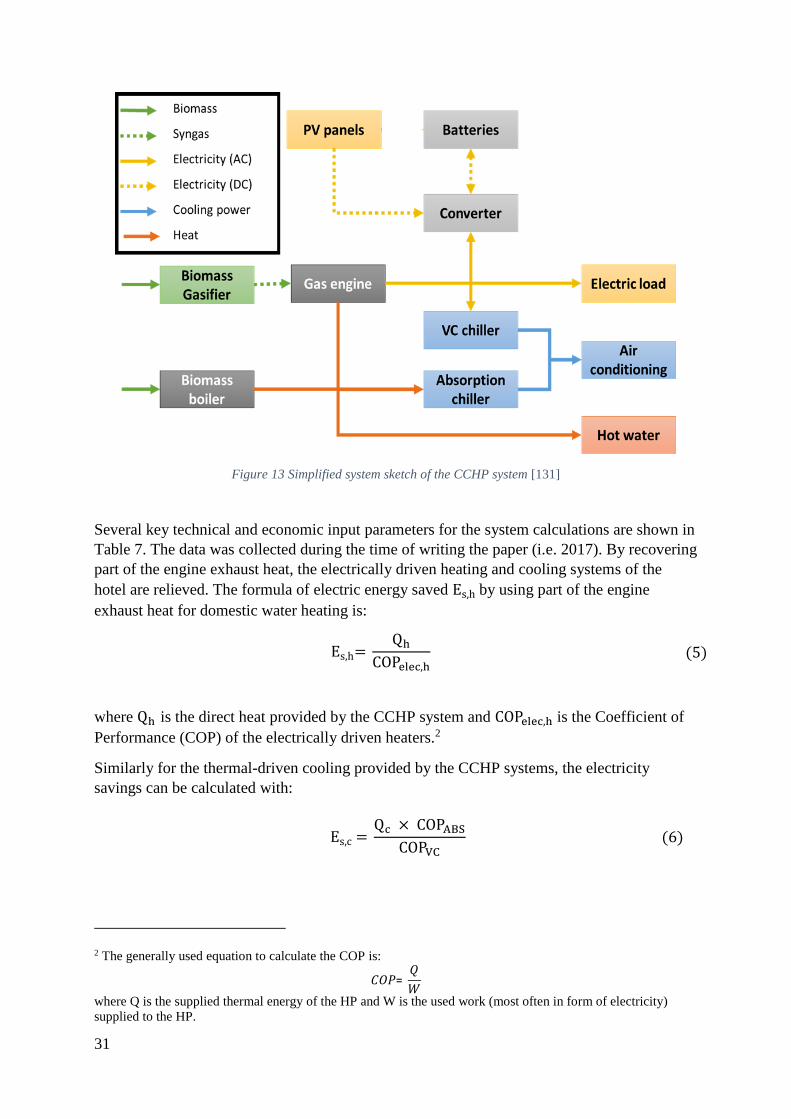
31
Figure 13 Simplified system sketch of the CCHP system [131]
Several key technical and economic input parameters for the system calculations are shown in
Table 7. The data was collected during the time of writing the paper (i.e. 2017). By recovering
part of the engine exhaust heat, the electrically driven heating and cooling systems of the
hotel are relieved. The formula of electric energy saved Es,h by using part of the engine
exhaust heat for domestic water heating is:
Es,h= Qh
COPelec,h (5)
where Qh is the direct heat provided by the CCHP system and COPelec,h is the Coefficient of
Performance (COP) of the electrically driven heaters.2
Similarly for the thermal-driven cooling provided by the CCHP systems, the electricity
savings can be calculated with:
Es,c = Qc × COPABS
COPVC (6)
2 The generally used equation to calculate the COP is:
𝐶𝑂𝑃= 𝑄
𝑊
where Q is the supplied thermal energy of the HP and W is the used work (most often in form of electricity)
supplied to the HP.
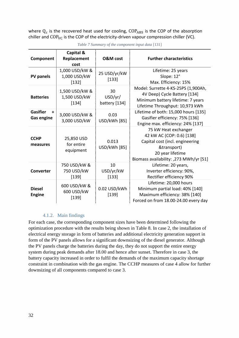
32
where Qc is the recovered heat used for cooling, COPABS is the COP of the absorption chiller and COPVC is the COP of the electricity-driven vapour compression chiller (VC).
Table 7 Summary of the component input data [131]
Component Capital &
Replacement cost
O&M cost Further characteristics
PV panels 1,000 USD/kW & 1,000 USD/kW
[132]
25 USD/yr/kW [133]
Lifetime: 25 years Slope: 12°
Max. Efficiency: 15%
Batteries 1,500 USD/kW & 1,500 USD/kW
[134]
30 USD/yr/
battery [134]
Model: Surrette 4-KS-25PS (1,900Ah, 4V Deep) Cycle Battery [134]
Minimum battery lifetime: 7 years Lifetime Throughput: 10,973 kWh
Gasifier + Gas engine
3,000 USD/kW & 3,000 USD/kW
0.03 USD/kWh [85]
Lifetime of both: 15,000 hours [135] Gasifier efficiency: 75% [136]
Engine max. efficiency: 24% [137]
CCHP measures
25,850 USD for entire
equipment
0.013 USD/kWh [85]
75 kW Heat exchanger 42 kW AC (COP: 0.6) [138]
Capital cost (incl. engineering &transport)
20 year lifetime Biomass availability: ,273 MWh/yr [51]
Converter 750 USD/kW &
750 USD/kW [139]
10 USD/yr/kW
[133]
Lifetime: 20 years, Inverter efficiency: 90%, Rectifier efficiency 90%
Diesel Engine
600 USD/kW & 600 USD/kW
[139]
0.02 USD/kWh [139]
Lifetime: 20,000 hours Minimum partial load: 40% [140] Maximum efficiency: 38% [140]
Forced on from 18.00-24.00 every day
4.1.2. Main findings
For each case, the corresponding component sizes have been determined following the
optimization procedure with the results being shown in Table 8. In case 2, the installation of
electrical energy storage in form of batteries and additional electricity generation support in
form of the PV panels allows for a significant downsizing of the diesel generator. Although
the PV panels charge the batteries during the day, they do not support the entire energy
system during peak demands after 18.00 and hence after sunset. Therefore in case 3, the
battery capacity increased in order to fulfil the demands of the maximum capacity shortage
constraint in combination with the gas engine. The CCHP measures of case 4 allow for further
downsizing of all components compared to case 3.

33
Table 8 Optimal system configurations for all cases [131]
Component Case 1
(Diesel-Grid)
Case 2 (Solar-Assisted)
Case 3
(Bio-Solar)
Case 4 (Bio-Solar
CCHP)
Diesel generator 160 kW 90 kW - - Gasifier + Gas
engine - - 50 kW 40 kW
PV panels - 200 kW 85 kW 85 kW
Batteries (Nom. Capacity)
- 42 kW in 7
strings (319 kWh)
84 kW in 14 strings
(638 kWh)
48 kW in 8 strings
(365 kWh) Converter - 60 kW 50 kW 45 kW
Boiler - - - 75 kW
The main economic and environmental findings of the study are summarized in Figure 14. All
three of the proposed RES systems are more cost-effective over the project lifetime of 20
years than the reference system, however all of them require higher investment capital too.
The higher costs of the reference case system are mainly caused by higher fuel and electricity
costs. Notably, the much easier-to-install system of case 2 shows a similarly good economic
performance as the complicated system of case 4, albeit it may not lead to full energy
autonomy and requires more capital investment. Case 4 would lead to lifetime savings of
nearly 30% equivalent to more than 500,000 USD, which could be used as a reasoned
argument to convince possible investors. The yearly CO2 emissions of the biomass-based
systems due to operation would be zero as the biomass has been considered carbon neutral
assuming it is harvested according to sustainable management measures. However, this
excludes emissions due to biomass transport to the system site and any inherent emissions for
constructing as well as eventually destructing the required machinery. While the capital
investment costs are foreseeable during project design and installation, the fuel costs can vary.
The results of the sensitivity analysis have shown that the fuel costs have a larger impact on
the systems of cases 1 and 2, meaning that the biomass-based systems are more robust
towards fuel price shocks.
The holistic benefits and drawbacks of the proposed CCHP system not just for the hotel
owner but also for other island inhabitants are summarized in Figure 15. By implementing
long-term biomass supply contracts between local farmers and the hotel owner, the biomass
farmers would have an additional and stable income source. The local administration would
benefit by reducing the strain on the local electricity grid and increasing the autonomy of their
entire energy system. Apart from the aforementioned techno-economic benefits of the CCHP
system, the hotel owner could also promote his resort as more eco-friendly.

34
Figure 14 Comparison of NPC, capital investment, and CO2 emissions for all four cases [131]
Figure 15 Benefits of a smart CCHP system for various interest groups of the Andaman Islands [131]
4.1.3. Concluding remarks
The study responds directly to the two research questions asked in Chapter 1.1 showing that
for islands with insufficiently supplied and deficiently managed fossil-fuelled energy systems,
a well-designed SBP system can significantly outperform the reference system economically
and environmentally. Additionally, when setting up an intelligent biomass supply structure,
not just one singular entity but the entire island society could benefit. However, the potential
of biomass especially on smaller islands is much more limited, meaning that the SBP
1,956.7
96.0
365.0
1,431.9
362.0174.8
1,630.0
398.5
0.0
1,377.8
336.6
0.0 0
500
1 000
1 500
2 000
2 500
NPC for 20 years (in thou. of $) Capital Investment (in thou. of $) CO₂-emissions during operation (t/year)
Case 1 Case 2 Case 3 Case 4

35
approach can only partly help with the island’s energy transition. Other RES cannot be
discarded when aiming for a 100% renewable electricity supply. Additionally, although the
SBP system outperforms the reference system in theory, practical obstacles like high design
complexity, augmented maintenance and operation requirements, and increased capital
investment costs will slow down the deployment of such systems.
Specifically for the PhD project, it should be noted that HOMER was proven to be an efficient
but in itself limited tool in energy system modelling. Although the electrical performance of
the studied systems was calculated entirely in HOMER, many thermodynamic calculations
related for example to the ABS or the engine control had to be computed externally and could
not influence the optimization process.

36
4.2. Techno-economic optimization model for polygeneration and hybrid
energy storage systems (Paper III)
In order to maximise the conversion efficiency of a given biomass resource, in the following
study an optimization model for a HESS with a novel dispatch control was developed.
Specifically, a novel dispatch control was employed for a biogas-battery storage combination
for a rural locality in Bolivia without connection to a larger national grid, which is hence
working in island-mode. While the biogas can serve as a long-term storage, the batteries can
cover lower electric loads and load fluctuations allowing for the biogas engine to operate at
higher efficiencies. To maximize the total system efficiency, a membrane distillation (MD)
unit has been considered to use recovered heat for potable water generation.
4.2.1. Case description and technical input
Based on official data from the Bolivian electricity agency (Autoridad de Fiscalización y
Control Social de Electricidad) a demand profile for the locality has been created. The
average monthly demand fluctuations are between -10% and +10% and the total annual
electricity consumption of the village has been calculated to be 1,342 MWh [141]. The
demand of one exemplary October week is presented in Figure 16. Similarly to the demand,
an analysis of the available biomass resources based on the quantity of animals and humans
living in the area has been conducted using data from the national statistics institute
[142,143]. The total daily biogas yield has been estimated to be 593 m3/day equivalent to
4,115 kWh/day. The conditions for solar energy have also been considered as favourable with
4.84 kWh/m2/day [144]. The reference system is based on diesel generators, where the diesel
has to be transported to the locality via trucks.
Figure 16 Electricity demand for the first week in October (Monday to Sunday)
A proposal of one polygeneration HESS layout for which the dispatch control can be used is
shown in Figure 17 and a list of key technical and economic variables is given in Table 9.
Using agricultural residues and animal waste, the biogas digester produces biogas to be stored
in the biogas tank and eventually to be combusted in the ICE. The generated electricity from
the engine-generator couple as well as from the PV panels either serves the electricity demand

37
of the end client directly or is stored in the batteries. A MD unit can use the recovered heat
from the engine to produce high quality potable water. The heat passed on to the cooling
water circuit of the MD unit can then further be used to support the anaerobic digestion
process. A detailed description of the MD unit circuit is given by Khan et al. [111]. If the
temperature of the jacket water cooling circuit is too high for engine entry, it can be further
cooled down using an additional cooling reservoir. For the MD unit, for pumping, and for the
biogas compression, a considerable amount of electricity is required, so that the combined
electricity demand of the polygeneration system and the end client is higher than for the
reference case. The dispatch control strategy takes this extra demand of electricity into
account and decides when and how to use the engine and the batteries.
An. Digester
HEx12
Biogas Compressor
Biogas Cleanup
BiogasEngine
5
Gen22
10
12
PV
Icons designed by Skyclick and Freepik from www.flaticon.com
Conv.25
Battery system
Cooling Reservor
15
HEx3
13
11
Gas exhaust
9
20
Fresh water tank
24
Electricity demand
27
28
1
1: mbio,AD
2: mbiog,uncleaned
3: mfert,AD
4: mbiog,cleaned
5: mbiog,fromstorage
6: mair,engine
7: mWP,cold,in
8: mWP,cold,out
9: mcooling,afterengine
10: mexhgas,hot
11: mexhgas,cold
12: mcooling,afterHEx1
13: mcooling,afterHEx2
14: mcooling,afterHEx3
15: mCT,in
16: mCT,out
17: mfeed,hot
18: mfeed,cold
19: mfeed,return
20: mcleanwater
21: mmake-upwater
22: Eeng,kinetic
23: Egen,elec
24: Ebattery
25: EPV,conv
26: EPV, bat
27: Econv
28: Eendclient
6
3
16
14
El. Control System
19
4
23
HEx2
18
17
7
8
Biogas Storage
MembraneDisti.
26
Storage Tank
21
Figure 17 System sketch of a particular bio-solar polygeneration system with hybrid storage [145]
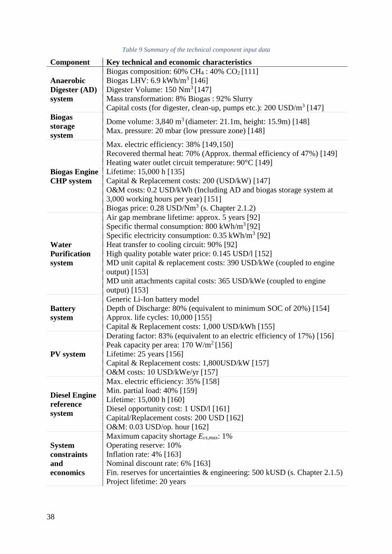
38
Table 9 Summary of the technical component input data
Component Key technical and economic characteristics
Anaerobic
Digester (AD)
system
Biogas composition: 60% CH4 : 40% CO2 [111]
Biogas LHV: 6.9 kWh/m3 [146]
Digester Volume: 150 Nm3 [147]
Mass transformation: 8% Biogas : 92% Slurry
Capital costs (for digester, clean-up, pumps etc.): 200 USD/m3 [147]
Biogas
storage
system
Dome volume: 3,840 m3 (diameter: 21.1m, height: 15.9m) [148]
Max. pressure: 20 mbar (low pressure zone) [148]
Biogas Engine
CHP system
Max. electric efficiency: 38% [149,150]
Recovered thermal heat: 70% (Approx. thermal efficiency of 47%) [149]
Heating water outlet circuit temperature: 90°C [149]
Lifetime: 15,000 h [135]
Capital & Replacement costs: 200 (USD/kW) [147]
O&M costs: 0.2 USD/kWh (Including AD and biogas storage system at
3,000 working hours per year) [151]
Biogas price: 0.28 USD/Nm3 (s. Chapter 2.1.2)
Water
Purification
system
Air gap membrane lifetime: approx. 5 years [92]
Specific thermal consumption: 800 kWh/m3 [92]
Specific electricity consumption: 0.35 kWh/m3 [92]
Heat transfer to cooling circuit: 90% [92]
High quality potable water price: 0.145 USD/l [152]
MD unit capital & replacement costs: 390 USD/kWe (coupled to engine
output) [153]
MD unit attachments capital costs: 365 USD/kWe (coupled to engine
output) [153]
Battery
system
Generic Li-Ion battery model
Depth of Discharge: 80% (equivalent to minimum SOC of 20%) [154]
Approx. life cycles: 10,000 [155]
Capital & Replacement costs: 1,000 USD/kWh [155]
PV system
Derating factor: 83% (equivalent to an electric efficiency of 17%) [156]
Peak capacity per area: 170 W/m2 [156]
Lifetime: 25 years [156]
Capital & Replacement costs: 1,800USD/kW [157]
O&M costs: 10 USD/kWe/yr [157]
Diesel Engine
reference
system
Max. electric efficiency: 35% [158]
Min. partial load: 40% [159]
Lifetime: 15,000 h [160]
Diesel opportunity cost: 1 USD/l [161]
Capital/Replacement costs: 200 USD [162]
O&M: 0.03 USD/op. hour [162]
System
constraints
and
economics
Maximum capacity shortage Ecs,max: 1%
Operating reserve: 10%
Inflation rate: 4% [163]
Nominal discount rate: 6% [163]
Fin. reserves for uncertainties & engineering: 500 kUSD (s. Chapter 2.1.5)
Project lifetime: 20 years

39
The optimization approach is based on the HOMER procedure, but has been augmented by
connecting HOMER to the MATLAB engine, where the dispatch control has been
programmed. The optimization and analysis procedure is visualized in Figure 18. The
MATLAB algorithm enables three major capabilities within the HOMER environment:
1. Determination of optimal component sizes given varying biomass provision as well as
fluctuating electricity demands.
2. To guarantee that the biogas engine is running whenever possible with maximum
electric efficiency by using the proposed dispatch control. In turn, this ensures that the
biomass is used in the most efficient way.
3. To allow for a heat demand profiled directly coupled to the engine heat generation
instead of a pre-determined, rigid heat profile. Thus the engine is focused on
electricity generation, but the generated heat will be used to its full potential as well.
The additional electric load caused by the pumps and MD devices has been
programmed as a parasitic load reducing the electricity of the engine into the control
algorithm.
For an environmental comparison of the systems, the total emitted mass of carbon dioxide,
CO2,tot, has been used and calculated as follows:
mCO2,tot = mCO2,transp + mCO2,comb (7)
where mCO2,transp is the mass of CO2 emitted due to transport of biomass to the system and
mCO2,comb is the mass of CO2 emitted due to combustion. It should be noted, that biomass
combustion is again considered carbon neutral.
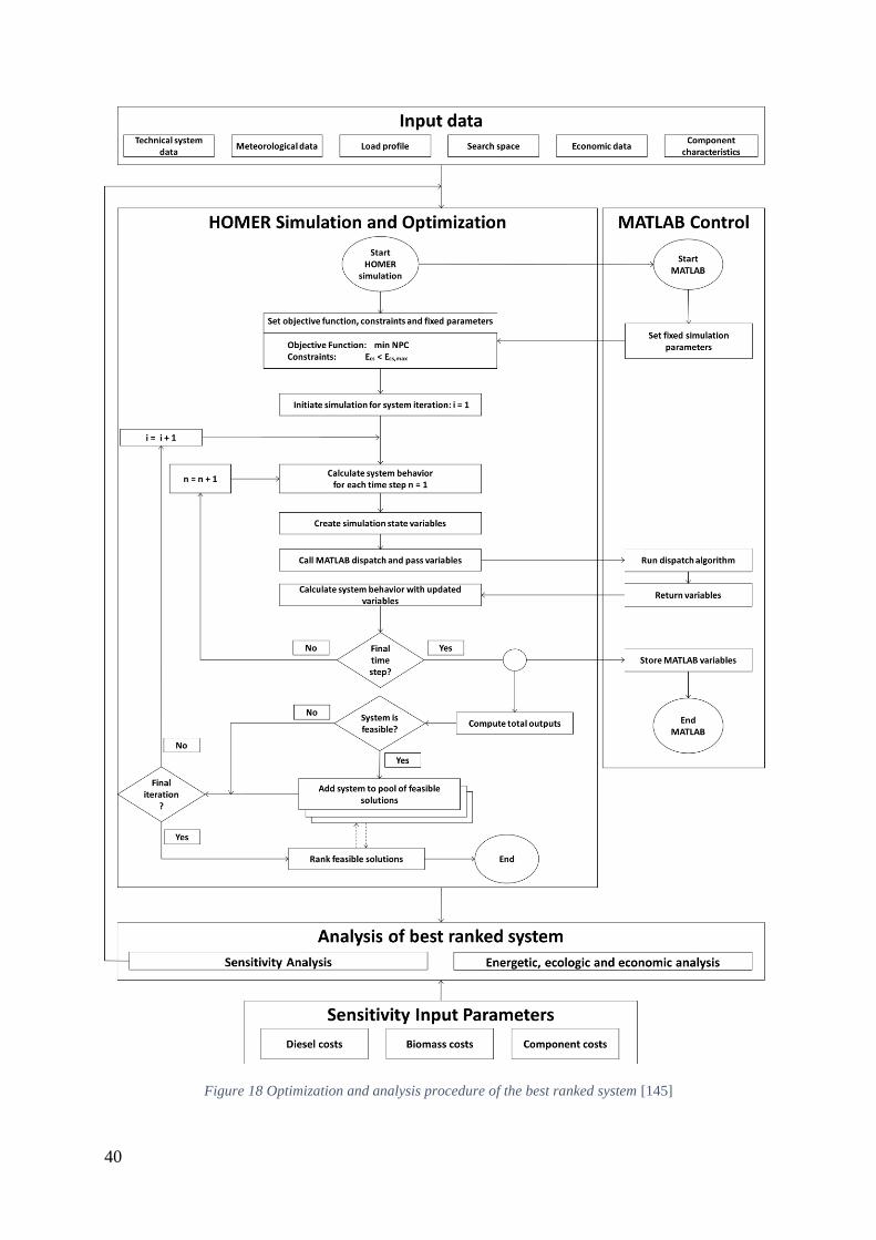
40
Figure 18 Optimization and analysis procedure of the best ranked system [145]
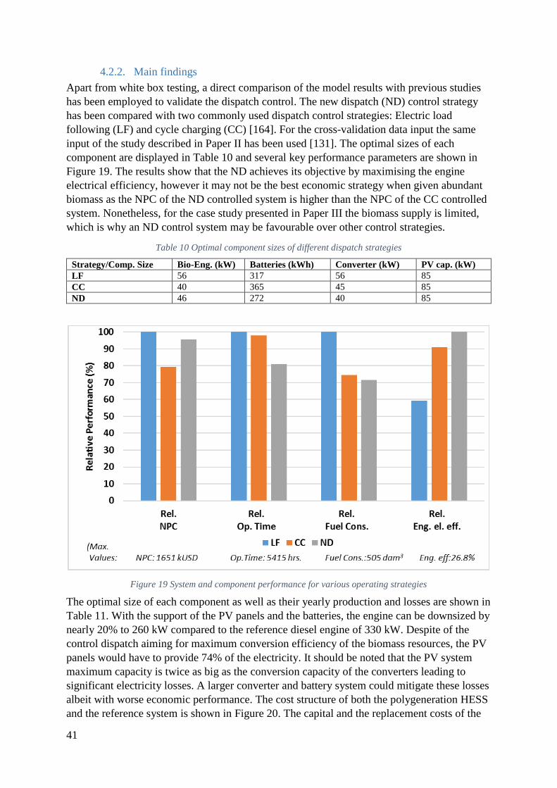
41
4.2.2. Main findings
Apart from white box testing, a direct comparison of the model results with previous studies
has been employed to validate the dispatch control. The new dispatch (ND) control strategy
has been compared with two commonly used dispatch control strategies: Electric load
following (LF) and cycle charging (CC) [164]. For the cross-validation data input the same
input of the study described in Paper II has been used [131]. The optimal sizes of each
component are displayed in Table 10 and several key performance parameters are shown in
Figure 19. The results show that the ND achieves its objective by maximising the engine
electrical efficiency, however it may not be the best economic strategy when given abundant
biomass as the NPC of the ND controlled system is higher than the NPC of the CC controlled
system. Nonetheless, for the case study presented in Paper III the biomass supply is limited,
which is why an ND control system may be favourable over other control strategies.
Table 10 Optimal component sizes of different dispatch strategies
Strategy/Comp. Size Bio-Eng. (kW) Batteries (kWh) Converter (kW) PV cap. (kW)
LF 56 317 56 85
CC 40 365 45 85
ND 46 272 40 85
Figure 19 System and component performance for various operating strategies
The optimal size of each component as well as their yearly production and losses are shown in
Table 11. With the support of the PV panels and the batteries, the engine can be downsized by
nearly 20% to 260 kW compared to the reference diesel engine of 330 kW. Despite of the
control dispatch aiming for maximum conversion efficiency of the biomass resources, the PV
panels would have to provide 74% of the electricity. It should be noted that the PV system
maximum capacity is twice as big as the conversion capacity of the converters leading to
significant electricity losses. A larger converter and battery system could mitigate these losses
albeit with worse economic performance. The cost structure of both the polygeneration HESS
and the reference system is shown in Figure 20. The capital and the replacement costs of the

42
polygeneration are much higher than those of the reference system, but the much lower fuel
costs and the water sales lead to better project lifetime costs, so that the total polygeneration
system would cost 22% less over its lifetime.
Table 11 Optimal system component parameters [145]
Component Size Yearly Elec.
Production
Additional
electricity expenses
PV system 1,075 kW (~6,320 m2
[156]) 1,602 MWh/yr (74%)
486 MWh/yr
(excess)
Battery system 2,250 kWh 556 MWh/yr (annual
throughput) 49 MWh/yr (losses)
Converter system 450 kW 1,876 MWh/yr
(Inverter output)
138 MWh/yr
(losses)
Biogas system 260 kW 554 MWh/yr (26%) 145 MWh/yr
(parasitic demand) MD unit system
Membrane area 16.7 m2
(18 modules)
800 m3/yr (= 2,190
l/day)
Reference Diesel
system 330 kW 1,337 MWh/yr -
Figure 20 Summary of the NPC values for the polygeneration system and the reference system [145]
Figure 21 shows how the electricity demand is satisfied by the polygeneration system for one
exemplary October week. The PV panels cover the load and charge the batteries during the
day, while the gas engine and the batteries cover the nightly loads. As shown in Figure 22, the
ICE is operating nearly all the time at full capacity (at 260 kWe) and hence with maximum

43
electric efficiency as aimed for by the dispatch control. The environmental comparison of
both systems has shown that the polygeneration HESS would lower CO2 emissions of the
locality’s energy system by 98%. The sensitivity analysis indicates that the polygeneration
HESS is much more robust towards fuel price changes and hence would increase the
locality’s financial autonomy immensely.
Figure 21 Electric power load and generation for one week in high demand season (October) [145]
Figure 22 Biogas engine output for each hour of the year [145]
4.2.3. Concluding remarks
The study displays that even in mild climates that are unfavourable for CCHP (due to low
demand for heating and cooling), a well-designed polygeneration system can still be
economically viable, but can also bring more energy autonomy and decrease emissions
significantly. This can be attributed to the high flexibility of the polygeneration concept,
which in this study has been expressed by using recovered heat from the engine in a MD unit
for potable water generation. The study also responds directly to the question on how the

44
design and the control of a specific polygeneration system are directly coupled to each other
and dictate the techno-performance of the SBP together.
The study incorporates the increasingly popular HESS concept, where the biomass works as
the long-term (“marathon runner”) and the batteries as the short-term (“sprinter”) storage
technologies. The direct contributions of the study to the science are the proposed modelling
approach, the subsequently developed model, and the presented specific polygeneration
system. All three contributions encourage the combined use of HESS and polygeneration
concepts.
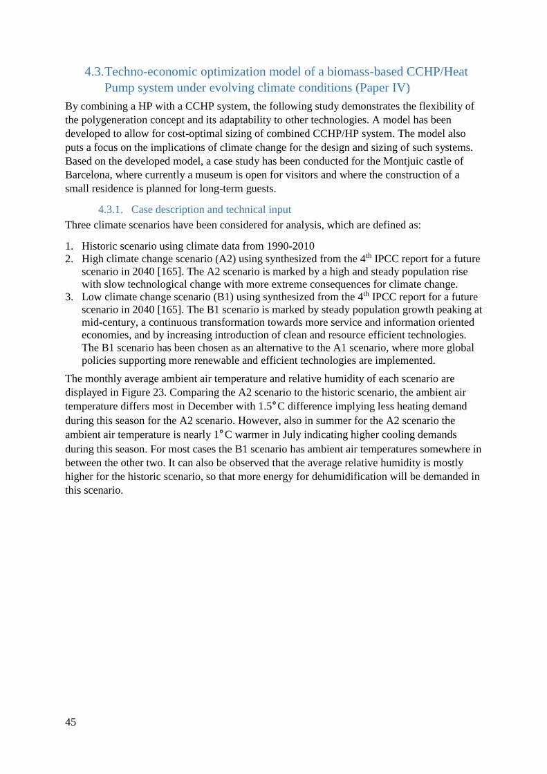
45
4.3. Techno-economic optimization model of a biomass-based CCHP/Heat
Pump system under evolving climate conditions (Paper IV)
By combining a HP with a CCHP system, the following study demonstrates the flexibility of
the polygeneration concept and its adaptability to other technologies. A model has been
developed to allow for cost-optimal sizing of combined CCHP/HP system. The model also
puts a focus on the implications of climate change for the design and sizing of such systems.
Based on the developed model, a case study has been conducted for the Montjuic castle of
Barcelona, where currently a museum is open for visitors and where the construction of a
small residence is planned for long-term guests.
4.3.1. Case description and technical input
Three climate scenarios have been considered for analysis, which are defined as:
1. Historic scenario using climate data from 1990-2010
2. High climate change scenario (A2) using synthesized from the 4th IPCC report for a future
scenario in 2040 [165]. The A2 scenario is marked by a high and steady population rise
with slow technological change with more extreme consequences for climate change.
3. Low climate change scenario (B1) using synthesized from the 4th IPCC report for a future
scenario in 2040 [165]. The B1 scenario is marked by steady population growth peaking at
mid-century, a continuous transformation towards more service and information oriented
economies, and by increasing introduction of clean and resource efficient technologies.
The B1 scenario has been chosen as an alternative to the A1 scenario, where more global
policies supporting more renewable and efficient technologies are implemented.
The monthly average ambient air temperature and relative humidity of each scenario are
displayed in Figure 23. Comparing the A2 scenario to the historic scenario, the ambient air
temperature differs most in December with 1.5°C difference implying less heating demand
during this season for the A2 scenario. However, also in summer for the A2 scenario the
ambient air temperature is nearly 1°C warmer in July indicating higher cooling demands
during this season. For most cases the B1 scenario has ambient air temperatures somewhere in
between the other two. It can also be observed that the average relative humidity is mostly
higher for the historic scenario, so that more energy for dehumidification will be demanded in
this scenario.

46
Figure 23 Monthly average air temperatures and humidity for all three scenarios [166]
Apart from the climate data, information on the building structure within the Montjuic castle
has been collected. Some key data on the buildings structure is given in the Annex. Using the
climate and building structure data as inputs for the DM, the thermal and electric demands
have been calculated. The results of the thermal demand of the demand analysis for the
historic scenario are visualized in Figure 24, whereas Table 12 shows the total sums of all
thermal demands. Cooling energy is not just required for space cooling but also in
considerable amounts for dehumidification due to the humidity of the local climate. The
demand for heating in the historic scenario is nearly three times as much as the demand for
cooling, while for the A2 scenario the total yearly heating demand is more than 10% lower.
On the contrary, for summery the cooling demand in the A2 scenario is up to 15% higher
compared to the historic scenario. Due to the continuing demand DHW, there is also a
constant need for heating during all of the year. As the structure is open nearly all days during
the whole year, the electric demand for non-thermal services has been considered constant
during of the year with a slightly decreased demand on the weekend due to less administration
workers coming as shown in Figure 25.

47
Figure 24 Daily thermal energy demands for the historic scenario [166]
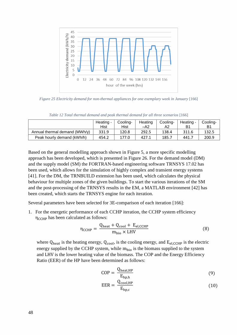
48
Figure 25 Electricity demand for non-thermal appliances for one exemplary week in January [166]
Table 12 Total thermal demand and peak thermal demand for all three scenarios [166]
Heating -
Hist Cooling-
Hist Heating –A2
Cooling-A2
Heating -B1
Cooling-B1
Annual thermal demand (MWh/y) 331.9 120.8 292.5 138.4 311.6 132.5
Peak hourly demand (kWh/h) 454.2 177.0 427.1 185.7 441.7 200.9
Based on the general modelling approach shown in Figure 5, a more specific modelling
approach has been developed, which is presented in Figure 26. For the demand model (DM)
and the supply model (SM) the FORTRAN-based engineering software TRNSYS 17.02 has
been used, which allows for the simulation of highly complex and transient energy systems
[41]. For the DM, the TRNBUILD extension has been used, which calculates the physical
behaviour for multiple zones of the given buildings. To start the various iterations of the SM
and the post-processing of the TRNSYS results in the EM, a MATLAB environment [42] has
been created, which starts the TRNSYS engine for each iteration.
Several parameters have been selected for 3E-comparison of each iteration [166]:
1. For the energetic performance of each CCHP iteration, the CCHP system efficiency
ηCCHP has been calculated as follows:
ηCCHP = Qheat + Qcool + Eel,CCHP
mbio × LHV (8)
where Qheat is the heating energy, Qcool, is the cooling energy, and Eel,CCHP is the electric
energy supplied by the CCHP system, while mbio is the biomass supplied to the system
and LHV is the lower heating value of the biomass. The COP and the Energy Efficiency
Ratio (EER) of the HP have been determined as follows:
COP = Qheat,HPEhp,h
(9)
EER = Qcool,HPEhp,c
(10)
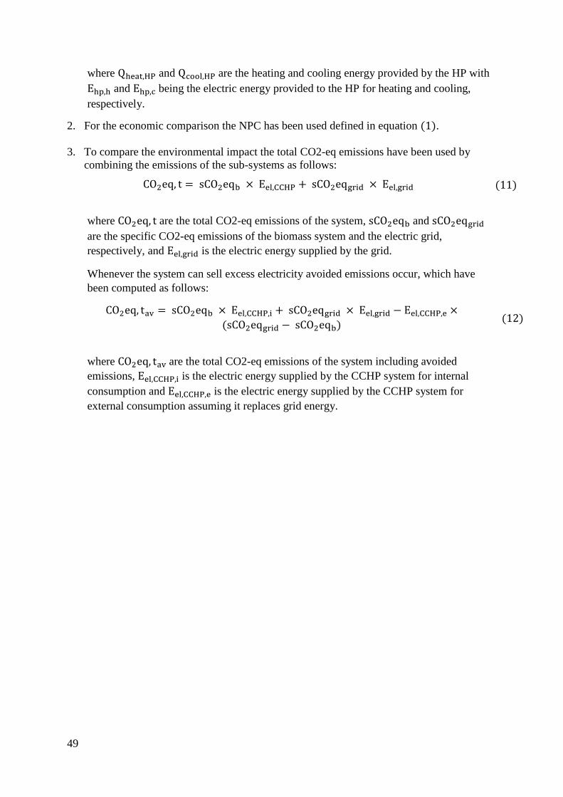
49
where Qheat,HP and Qcool,HP are the heating and cooling energy provided by the HP with
Ehp,h and Ehp,c being the electric energy provided to the HP for heating and cooling,
respectively.
2. For the economic comparison the NPC has been used defined in equation (1).
3. To compare the environmental impact the total CO2-eq emissions have been used by
combining the emissions of the sub-systems as follows:
CO2eq, t = sCO2eqb × Eel,CCHP + sCO2eqgrid × Eel,grid (11)
where CO2eq, t are the total CO2-eq emissions of the system, sCO2eqb and sCO2eqgrid
are the specific CO2-eq emissions of the biomass system and the electric grid,
respectively, and Eel,grid is the electric energy supplied by the grid.
Whenever the system can sell excess electricity avoided emissions occur, which have
been computed as follows:
CO2eq, tav = sCO2eqb × Eel,CCHP,i + sCO2eqgrid × Eel,grid − Eel,CCHP,e ×
(sCO2eqgrid − sCO2eqb) (12)
where CO2eq, tav are the total CO2-eq emissions of the system including avoided
emissions, Eel,CCHP,i is the electric energy supplied by the CCHP system for internal
consumption and Eel,CCHP,e is the electric energy supplied by the CCHP system for
external consumption assuming it replaces grid energy.

50
Figure 26 Modelling approach of CCHP/HP systems for various climate change scenarios [166]
Using the results of the DM, a CCHP/HP system has been designed with the primary
objective that both sub-systems can operate independently from the other. The designed
system is displayed in Figure 27. The CCHP system is fuelled by syngas produced by a
downdraft gasifier, which itself is fuelled by locally available wood chips. Before engine
entry, the syngas is filtered and cooled down by various clean-up units. After fuel combustion,
the kinetic energy of the engine is transformed to electric energy via a generator and used for
system internal demands, stored in the batteries, supplied to the end client, and/or sold to the
external electric grid. The model can take into account additional electricity served by PV

51
panels, although for the case study the PV panel capacity has been set to only 20 kWe,
because no larger area suitable for PV panel placement has been identified. An electric load
following control algorithm, which has been identified as one of the most suitable strategies
for Mediterranean climates [116], has been used:
1. If batteries and PV panels can supply sufficient electricity, the engine is turned off.
2. If batteries and PV panels cannot supply sufficient electricity, the engine is:
a) Set to minimum partial load, if the electricity demand after PV panel supply is
equal or lower than partial load. Excess electricity from the engine is stored in
the batteries and/or, in case the batteries are fully charged, sold to the grid.
b) Set to the remaining load, if the electricity demand after PV panels is in between
minimum partial load and maximum capacity of the engine
c) Set to maximum capacity, if the electricity demand after PV panels and batteries
exceeds the maximum capacity. All remaining demanded electricity is drawn
from the electric grid.
The engine exhaust gases after combustion transfer some of their heat to the engine jacket
water coming out from the engine in Heat Exchanger 1 (HEx1). Afterwards, the jacket water
transfers its heat to a hot water circuit in Heat Exchanger 2 (HEx2). In case the jacket water is
too hot for engine cooling, a post-cooler cools it down to 80°C. In case, cooling is needed, the
hot water drives an absorption chilling process within an ABS. Otherwise, the hot water
circuit transfers heat to the end client and then any remaining heat afterwards is stored in a hot
water tank. Similarly, the chilled water from the ABS provides cooling power to the end
client. During summer months, a cooling tank is employed to store chilled water whenever the
ABS can produce excess cooling. Whenever, the heating and cooling supply of the CCHP
system is not sufficient, the air-sourced HP (ASHP) is employed to provide any missing
thermal energy. The cooling capacity of the ABS has been set equal to the electricity
generation capacity of the engine as with this relationship the engine exhaust heat can satisfy
the ABS heat demand during full load.
A list of key technical and economic parameters used as input data are shown in Table 14 and
Table 15. For most components a linear relationship between costs and capacity has been
regarded as sufficiently accurate. However, for the investment costs of the ABS a logarithmic
function based in national data has been used [114,167]:
IAbs = −236.5 € × ln(maxCap) + 1,655.4 € (13) where 𝐼𝐴𝑏𝑠 is the installation costs per base capacity unit (in €/kWt) and maxCap is the
absorption chiller maximum capacity. For the electricity costs a dynamic price structure based
on data provided by the local administration has been used. A summary of prices and
emissions for electricity and biomass is given in Table 13.
Table 13 Prices and emissions for electricity and biomass input
Electric
grid*
Flexible electricity consumption costs:
off & flat & peak
62.66 €/MWh & 82.08 €/MWh & 94.52
€/MWh
Electric capacity costs 0.009477€/(kWcap·h)
Taxes: Electricity & VAT 5.1% & 21%

52
Electricity selling price 5.00 €/MWh [168]
CO2-emissions – Spanish grid -
𝑠𝐶𝑂2𝑒𝑞𝑔𝑟𝑖𝑑
265.5 g CO2/kWhe [169]
Biomass
Pre-treated wood splinter costs 90 €/t [170]
CO2-emissions – Gasification -
𝑠𝐶𝑂2𝑒𝑞𝑏
45 g CO2/kWhe [58]
*All electricity costs are based on electricity bills from 2018-2019

53
Icons designed by Skyclick and Freepik from www.flaticon.com
3
1: mbiomass
2: mgasifier,ash&char
3: mgasifier,air
4: mgasifier, exhaust gas
5: mgasifier,syngas
6: mcyclone,chars
7: mcyclone,syngas
8: msyngas,intake
9: mair,intake
10: Eeng,kinetic
Down-draft gasifier
Gasifier
Filter & CoolerCyclone
1
5
4
7
6
Syngas Engine
Gen
PV
Conv.14
Battery system
13
Client Electricity demand
12
16
El. Control System11
15
8
18
HEx 1 -Internal
HEx 2 – External
9
Absorption Chiller
2120
19
22
2
JacketPost-Cooler
23
24 25
26
27
Final Heat Consumption
28Hot Water
Tank
29
30
31Final CoolingConsumption
32
Cool Water Tank
33
34
35 36
Heat Pumps
37
38
21: meng,afterHEx1
22: meng,afterHEx2
23: meng,toEngine
24: mcooling,before
25: mcooling,after
26: mhotw,afterHEx2
27: mhotw,afterABS
28: mhotw,afterCons
29: mhotw,tanktoCons
30:mhotw,tanktoHEx2
39
10
11: Egen,elec
12: Econv,system
13: Ebat,conv
14: EPV,conv
15: EPV, bat
16: Eel_con,endclient
17: Eel, grid
18: meng,exhaust,hot
19: mHEx2,exhaust,cool
20: meng,afterEngine
31: mchillw,AbstoCons
32: mchillw,toTank
33:mchillw,TanktoCons
34: mchillw,TanktoAbs
35:mcoolw,toAbs
36: mcoolw,fromAbs
37:Qhp,heat
38: Qhp,cool
39: Eel_con,system*
*Including all other machinery
17
Figure 27 System sketch for the combined CCHP and HP system [166]
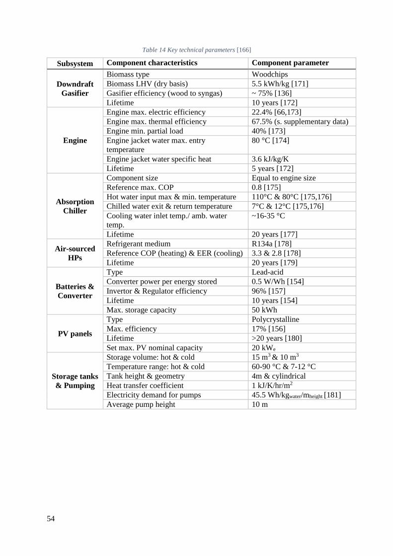
54
Table 14 Key technical parameters [166]
Subsystem Component characteristics Component parameter
Downdraft
Gasifier
Biomass type Woodchips
Biomass LHV (dry basis) 5.5 kWh/kg [171]
Gasifier efficiency (wood to syngas) ~ 75% [136]
Lifetime 10 years [172]
Engine
Engine max. electric efficiency 22.4% [66,173]
Engine max. thermal efficiency 67.5% (s. supplementary data)
Engine min. partial load 40% [173]
Engine jacket water max. entry
temperature
80 °C [174]
Engine jacket water specific heat 3.6 kJ/kg/K
Lifetime 5 years [172]
Absorption
Chiller
Component size Equal to engine size
Reference max. COP 0.8 [175]
Hot water input max & min. temperature 110°C & 80°C [175,176]
Chilled water exit & return temperature 7°C & 12°C [175,176]
Cooling water inlet temp./ amb. water
temp.
~16-35 °C
Lifetime 20 years [177]
Air-sourced
HPs
Refrigerant medium R134a [178]
Reference COP (heating) & EER (cooling) 3.3 & 2.8 [178]
Lifetime 20 years [179]
Batteries &
Converter
Type Lead-acid
Converter power per energy stored 0.5 W/Wh [154]
Invertor & Regulator efficiency 96% [157]
Lifetime 10 years [154]
Max. storage capacity 50 kWh
PV panels
Type Polycrystalline
Max. efficiency 17% [156]
Lifetime >20 years [180]
Set max. PV nominal capacity 20 kWe
Storage tanks
& Pumping
Storage volume: hot & cold 15 m3 & 10 m3
Temperature range: hot & cold 60-90 °C & 7-12 °C
Tank height & geometry 4m & cylindrical
Heat transfer coefficient 1 kJ/K/hr/m2
Electricity demand for pumps 45.5 Wh/kgwater/mheight [181]
Average pump height 10 m
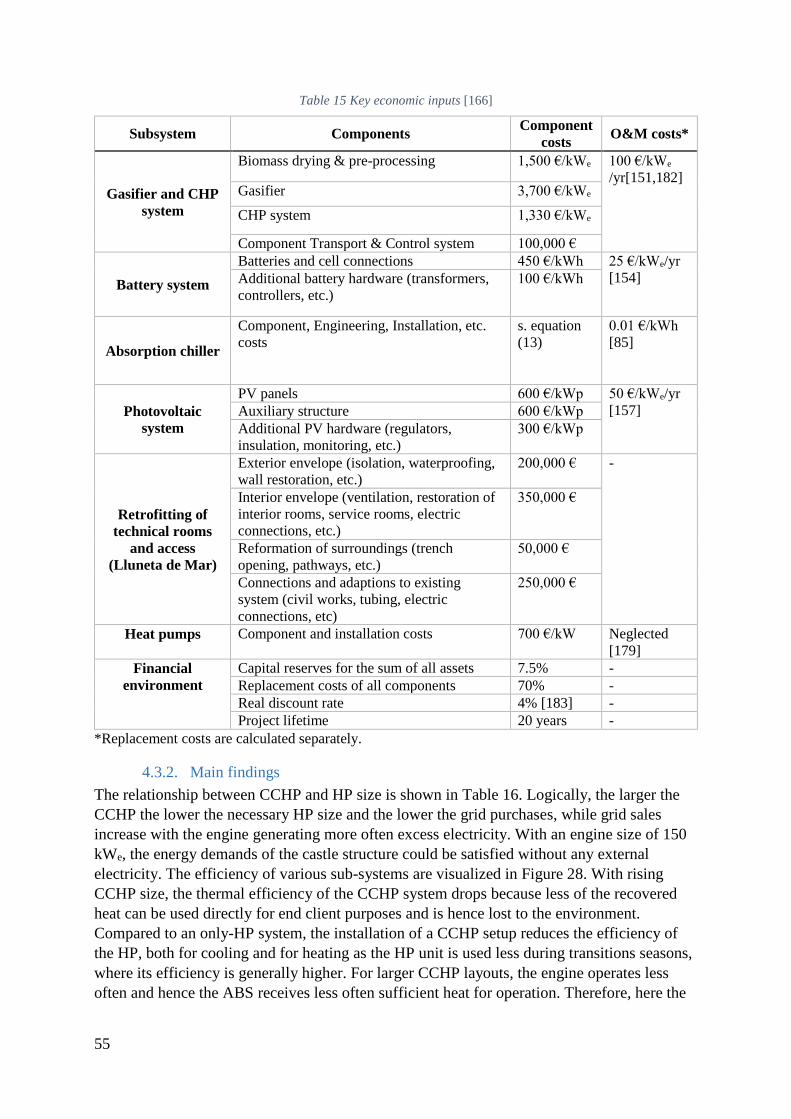
55
Table 15 Key economic inputs [166]
Subsystem Components Component
costs O&M costs*
Gasifier and CHP
system
Biomass drying & pre-processing 1,500 €/kWe 100 €/kWe
/yr[151,182] Gasifier 3,700 €/kWe
CHP system 1,330 €/kWe
Component Transport & Control system 100,000 €
Battery system
Batteries and cell connections 450 €/kWh 25 €/kWe/yr
[154] Additional battery hardware (transformers,
controllers, etc.)
100 €/kWh
Absorption chiller
Component, Engineering, Installation, etc.
costs
s. equation
(13)
0.01 €/kWh
[85]
Photovoltaic
system
PV panels 600 €/kWp 50 €/kWe/yr
[157] Auxiliary structure 600 €/kWp
Additional PV hardware (regulators,
insulation, monitoring, etc.)
300 €/kWp
Retrofitting of
technical rooms
and access
(Lluneta de Mar)
Exterior envelope (isolation, waterproofing,
wall restoration, etc.)
200,000 € -
Interior envelope (ventilation, restoration of
interior rooms, service rooms, electric
connections, etc.)
350,000 €
Reformation of surroundings (trench
opening, pathways, etc.)
50,000 €
Connections and adaptions to existing
system (civil works, tubing, electric
connections, etc)
250,000 €
Heat pumps Component and installation costs 700 €/kW Neglected
[179]
Financial
environment
Capital reserves for the sum of all assets 7.5% -
Replacement costs of all components 70% -
Real discount rate 4% [183] -
Project lifetime 20 years -
*Replacement costs are calculated separately.
4.3.2. Main findings
The relationship between CCHP and HP size is shown in Table 16. Logically, the larger the
CCHP the lower the necessary HP size and the lower the grid purchases, while grid sales
increase with the engine generating more often excess electricity. With an engine size of 150
kWe, the energy demands of the castle structure could be satisfied without any external
electricity. The efficiency of various sub-systems are visualized in Figure 28. With rising
CCHP size, the thermal efficiency of the CCHP system drops because less of the recovered
heat can be used directly for end client purposes and is hence lost to the environment.
Compared to an only-HP system, the installation of a CCHP setup reduces the efficiency of
the HP, both for cooling and for heating as the HP unit is used less during transitions seasons,
where its efficiency is generally higher. For larger CCHP layouts, the engine operates less
often and hence the ABS receives less often sufficient heat for operation. Therefore, here the
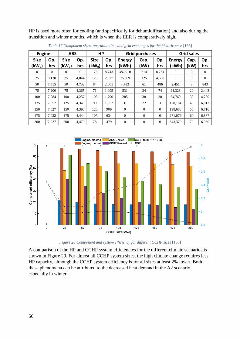
56
HP is used more often for cooling (and specifically for dehumidification) and also during the
transition and winter months, which is when the EER is comparatively high.
Table 16 Component sizes, operation time and grid exchanges for the historic case [166]
Figure 28 Component and system efficiency for different CCHP sizes [166]
A comparison of the HP and CCHP system efficiencies for the different climate scenarios is
shown in Figure 29. For almost all CCHP system sizes, the high climate change requires less
HP capacity, although the CCHP system efficiency is for all sizes at least 2% lower. Both
these phenomena can be attributed to the decreased heat demand in the A2 scenario,
especially in winter.
Engine ABS HP Grid purchases Grid sales
Size (kWe)
Op. hrs
Size (kWe)
Op. hrs
Size (kWe)
Op. hrs
Energy (kWh)
Cap. (kW)
Op. hrs
Energy (kWh)
Cap. (kW)
Op. hrs
0 0 0 0 173 8,743 382,910 214 8,764 0 0 0
25 8,120 25 4,844 125 2,527 76,069 125 4,508 0 0 0
50 7,515 50 4,732 84 2,001 4,783 61 486 2,451 8 843
75 7,200 75 4,365 71 1,995 531 24 74 21,323 20 2,443
100 7,084 100 4,257 108 1,790 285 38 28 64,769 30 4,280
125 7,052 125 4,340 90 1,352 31 22 3 128,184 40 6,012
150 7,027 150 4,393 120 909 0 0 0 198,683 50 6,716
175 7,032 175 4,444 105 634 0 0 0 271,076 60 6,887
200 7,027 200 4,479 78 479 0 0 0 343,370 70 6,980

57
Figure 29 Energetic system performances for different climate scenarios [166]
The economic performances of the only-HP and the different sized CCHP/HP systems for the
historic scenario are presented in Figure 30. For the only-HP system the electricity costs
outweigh the capital costs, while when adding a CCHP system of any size the fuel costs are
reduced significantly. However, only a small 25 kWe CCHP system would lead to lifetime
cost reductions, as all CCHP systems require high capital investment. The small CCHP
system would lead to cost-reductions of more than 7%. The impact of climate change on the
system design and component sizing is diminutive as can be observed from Figure 31. In an
all climate scenarios the combination with the smallest CCHP system of 25 kWe outperforms
all other options.
The CO2 emissions for the historic scenario are shown in Figure 32. The larger the CCHP
system the higher the emissions due to biomass (incl. harvesting and transport), however also
more emissions would be avoided as less electricity from the national grid would be
purchased and cleaner electricity would be sold to the grid. Interestingly, the high climate
change scenario would lead to lower emissions for all CCHP system sizes as shown in Figure
33.

58
Figure 30 NPC of components and the total system for the historic scenario [166]
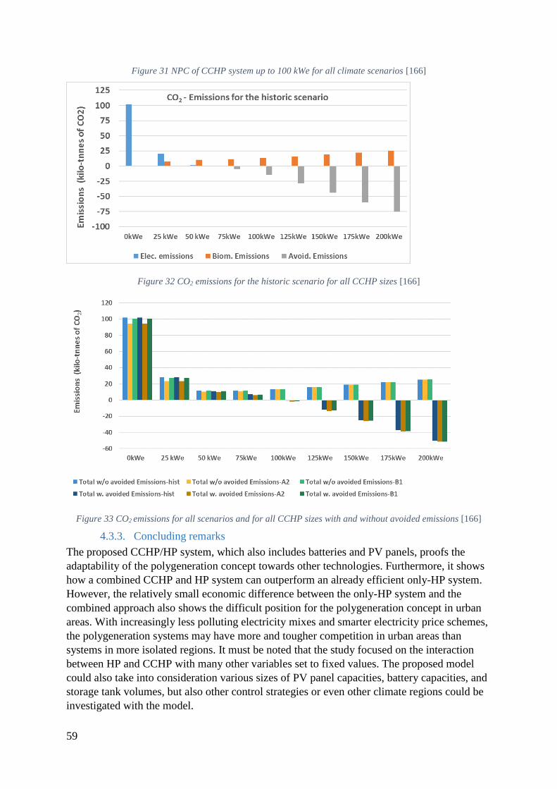
59
Figure 31 NPC of CCHP system up to 100 kWe for all climate scenarios [166]
Figure 32 CO2 emissions for the historic scenario for all CCHP sizes [166]
Figure 33 CO2 emissions for all scenarios and for all CCHP sizes with and without avoided emissions [166]
4.3.3. Concluding remarks
The proposed CCHP/HP system, which also includes batteries and PV panels, proofs the
adaptability of the polygeneration concept towards other technologies. Furthermore, it shows
how a combined CCHP and HP system can outperform an already efficient only-HP system.
However, the relatively small economic difference between the only-HP system and the
combined approach also shows the difficult position for the polygeneration concept in urban
areas. With increasingly less polluting electricity mixes and smarter electricity price schemes,
the polygeneration systems may have more and tougher competition in urban areas than
systems in more isolated regions. It must be noted that the study focused on the interaction
between HP and CCHP with many other variables set to fixed values. The proposed model
could also take into consideration various sizes of PV panel capacities, battery capacities, and
storage tank volumes, but also other control strategies or even other climate regions could be
investigated with the model.

60
The study responds to the question how climate change will impact the design and sizing of
SBP. It shows that the efficiencies of various sub-systems are directly affected by rising
ambient air and ground water temperatures, especially of the ABS and of the HP but also to a
lesser degree of the engine and the HEx. Although it seems counter-intuitive, the warmer the
future climate, the lower the efficiency of the combined system, but also the lower energy
consumption and costs. This can be explained by lower efficiencies of the HP when working
in summer, but much less demand for heating in winter. Nevertheless, the impact on the
calculated system economics and hence on the system design is not decisive enough to alter
the sizing of the components significantly.

61
4.4. Exergetic analysis of a small-scale CCHP/HP system based on biomass
gasification (Paper V)
Using the same input data as in the study of Chapter 4.3, a similar CCHP/HP system was
investigated for exergetic performance in the following study. Apart from all the equations for
the exergy calculations, the model developed for this study includes also a sub-model for the
chemical processes occurring in the downdraft gasifier. The methodological approach
followed in this study differs only slightly from the approach of the study presented in 4.3: no
scenario analysis for various climates has been conducted and the results have been post-
processed for exergetic performance instead of economic performance.
4.4.1. Case description and technical input
For the case study, the same electric and thermal demand data as for the historic case of
Chapter 4.3.1 has been used. However, the CCHP/HP system has been slightly altered. No
storage tanks, no batteries, and no PV panels have been considered for the sake of
simplification. The layout of the polygeneration is shown in Figure 34. For the computations
of the exergy several assumptions have been made:
1. The dead state is defined by the ambient air temperature and hence is dynamic.
2. All gases are assumed to be ideal gases.
3. The composition has been simplified to 79% nitrogen and 21% oxygen.
4. All ashes are considered to be unreactive.
5. Tar has been excluded from the model.
6. The heat capacity of graphite has been used for the heat capacity of char.
7. Moisture in biomass is considered liquid water, which will be fully evaporated during
gasification.
8. Potential and kinetic exergies have been neglected as have been exergy changes due to
pressure fluctuations.
Several chemical equations are necessary for calculating the exergetic performance of the
system and of the individual components. For all exergy flows the exergy has been defined as:
e = ech + eph (14)
The physical exergy of gases has been calculated with:
eph,g = cp[ (Ti − To) − TO × lnTiTo ] (15)
where Ti is the temperature of the individual gas stream i. The chemical exergy of gases has
been calculated with:
ech,g = ∑yi × bch,ii
+ RTo∑yi × ln(yi)
i
(16)
The physical exergy of liquids has been calculated with the following formula:
eph,l = (hi − ho) − To(si − so) (17)
For the exergy of thermal flows the following formula has been used:

62
eq = Q × (1 −ToTi) (18)
The formula of Szargut et al. [184,185] is employed to calculate the LHV of the biomass:
LHV = ech,biomass/β (19)
The values of the biomass exergy ech,biomass are provided by Song et al. [186],while β is
calculated as follows:
β =
{
1.0438 + 0.1882
wH
wC+ 0.0610
wO
wC+ 0.0404
wN
wC for
wO
wC ≤ 0.5
β =[1.0438+0.1882
wHwC
− 0.2509 wOwC
(1+0.7256 wHwC
)+0.0383wNwC
]
1−0.3035wOwC
for 0.5 ≤ wO
wC ≤ 2
}
(20)
For the gasification reaction of the biomass the following reaction has been assumed:
x1 CsHmOpNqSr + x2 O2 + x3 H2O
= x4CO2 + x5CO + x6H2 + x7CH4+x8C(char) + x9NO2 + x10 SO2 (21)
When x1 and the molecular structure of the biomass are determined, several sub-equations can
be derived from above equation to solve for the unknown variables:
Carbon equation: x1 × n = x4 + x5 + x6 + x7 (22)
Hydrogen equation: x1 × m + 2y3 = 2x6 + 4x7 (23)
Oxygen equation: x1 × p + 2 x2 + x3 = 2x4 + x5 + 2x9 + 2x10 (24)
Nitrogen equation: x1 × q = x9 (25)
Sulphur equation: x1 × r = x10 (26)
The product ratio of methane to hydrogen for small-scale fixed-bed co-current gasifiers at
1,200 K has been assumed to be [187]:
Hydrogen to methane ratio: x6 = 9x7 (27)
A key parameter for the gasification process is the Equivalent Ratio (ER), which describes the
ratio of actual air supply (and hence actual oxygen supply) over the stoichiometric air supply.
For optimal gasification the equivalence ratio (ER) has been assumed to be 0.4, where the
following product ratio of carbon dioxide to carbon monoxide is reached [188]:
CO2 to CO ratio: x4 = x5 (28)
Based on equations (14) - (28) and the system layout, the exergy efficiencies for each
component can be calculated as shown in Table 17.
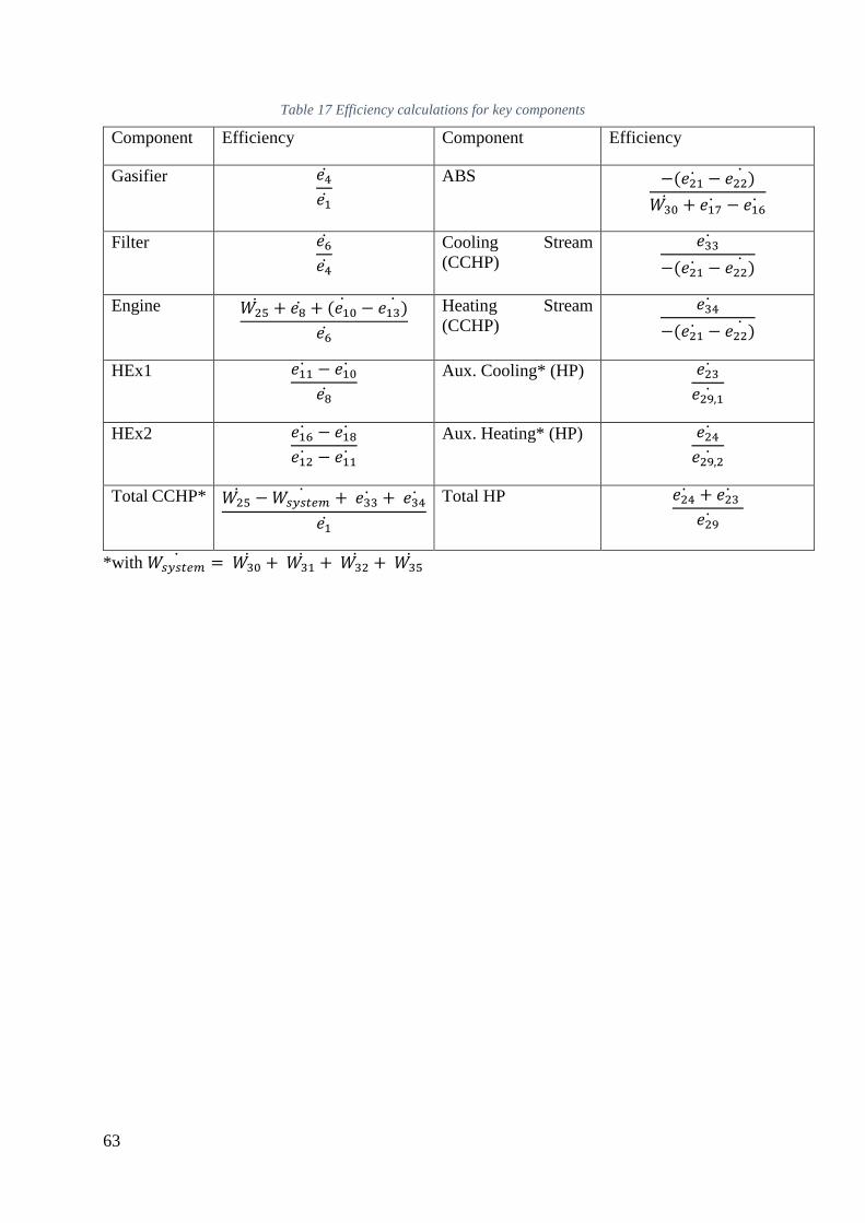
63
Table 17 Efficiency calculations for key components
Component Efficiency Component Efficiency
Gasifier 𝑒4𝑒1
ABS −(𝑒21 − 𝑒22)
𝑊30 + 𝑒17 − 𝑒16
Filter 𝑒6𝑒4
Cooling Stream
(CCHP)
𝑒33
−(𝑒21 − 𝑒22)
Engine 𝑊25 + 𝑒8 + (𝑒10 − 𝑒13)
𝑒6
Heating Stream
(CCHP)
𝑒34
−(𝑒21 − 𝑒22)
HEx1 𝑒11 − 𝑒10
𝑒8
Aux. Cooling* (HP) 𝑒23
𝑒29,1
HEx2 𝑒16 − 𝑒18
𝑒12 − 𝑒11
Aux. Heating* (HP) 𝑒24
𝑒29,2
Total CCHP* 𝑊25 − 𝑊𝑠𝑦𝑠𝑡𝑒𝑚
+ 𝑒33 + 𝑒34
𝑒1
Total HP 𝑒24 + 𝑒23
𝑒29
*with 𝑊𝑠𝑦𝑠𝑡𝑒𝑚 = 𝑊30
+ 𝑊31 + 𝑊32
+ 𝑊35
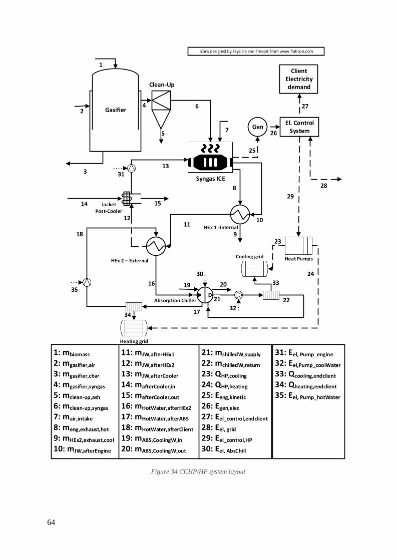
64
Icons designed by Skyclick and Freepik from www.flaticon.com
2
1: mbiomass
2: mgasifier,air
3: mgasifier,char
4: mgasifier,syngas
5: mclean-up,ash
6: mclean-up,syngas
7: mair,intake
8: meng,exhaust,hot
9: mHEx2,exhaust,cool
10: mJW,afterEngine
Down-draft gasifier
Gasifier
Clean-Up
1
4 6
5
Syngas ICE
Gen
Client Electricity demand
27
El. Control System26
8
HEx 1 -Internal
HEx 2 – External
7
Absorption Chiller
1110
9
12
3
JacketPost-Cooler
13
14 15
16
17
Heating grid
18
21 22
19 20
Heat Pumps
24
23
11: mJW,afterHEx1
12: mJW,afterHEx2
13: mJW,afterCooler
14: mafterCooler,in
15: mafterCooler,out
16: mHotWater,afterHEx2
17: mHotWater,afterABS
18: mHotWater,afterClient
19: mABS,CoolingW,in
20: mABS,CoolingW,out
29
25
31: Eel, Pump_engine
32: Eel,Pump_coolWater
33: Qcooling,endclient
34: Qheating,endclient
35: Eel, Pump_hotWater
21: mchilledW,supply
22: mchilledW,return
23: QHP,cooling
24: QHP,heating
25: Eeng,kinetic
26: Egen,elec
27: Eel_control,endclient
28: Eel, grid
29: Eel_control,HP
30: Eel, AbsChill
33
34
28
31
35
32
30
Cooling grid
Figure 34 CCHP/HP system layout

65
4.4.2. Main findings
For a CCHP/HP system with a 25 kWe engine the exergy efficiencies of the gasifier and the
clean-up are not affected by load changes or ambient temperatures and are 78% and 83%,
respectively. These can be considered typical values for wood-based gasification [189]. The
engine exergy efficiency fluctuates most of the time between 80% and 95% depending
heavily on the jacket water cooling temperature before engine entry and the partial load.
HEx1 transfers heat from the exhaust gas to the jacket water with an exergy efficiency of
50%-60% during most operations hours. When HEx2 transfers heat from the hot jacket water
loop to the hot water loop of the ABS, the exergy efficiency is most of the time at around
93%.
The exergy efficiencies of the absorption chiller, the heat streams to the consumer, and the
heat pumps of a CCHP/HP system with a 25 kWe engine are shown in Figure 35 and Figure
36. Interestingly, the exergy efficiency of the ABS varies the most and reaches peak values of
up to 95%. This can be attributed to the many input parameters (e.g. chilled water temperature
and mass flow, hot water temperature and mass flow, partial load, etc.). However, a clear
trend line indicating higher efficiencies in winter than in summer can be observed. The exergy
efficiencies of the final heat streams provided by the CCHP system are relatively stable with
the efficiency for heating and cooling hovering around 17% and 86%, respectively. The big
difference between the two values can be explained with the relatively larger temperature
difference between heat stream supply and ambient temperature. For the HP, the exergy
efficiency in heating mode ranges most of the operation times between 35% - 38%. It can also
be observed that even for the small CCHP system, HP heating is only needed for some winter
days, but not at all in summer. In cooling mode, the HP exergy efficiency fluctuates between
15% - 23% most of the operation times.
A comparison of the CCHP and the HP sub-system exergy efficiencies is shown in Figure 37.
The HP sub-system efficiency drops significantly from 40.5% for the only-HP case to 25.4%
for the smallest CCHP sub-system case. However, the smallest CCHP sub-system has the
highest exergy efficiency of the CCHP sub-systems with 13.3% and with a continuing
downwards trend for larger CCHP sub-systems. This can be explained by the decreased
utilization of recovered heat as well as the decreased efficiencies when operating more often
under lower partial loads. These exergy values are in range of the results found by other studies
for similarly mild climates [190,191].

66
Figure 35 Exergy efficiencies of the ABS and both heat streams (from the CCHP) for a 25 kWe CCHP system
Figure 36 Exergy efficiencies of the HP for a 25 kWe CCHP system

67
Figure 37 CCHP and HP subsystem exergy efficiencies for various sizes
4.4.3. Concluding remarks
By using an exergy analysis, the study focused on the technical aspects of the proposed
CCHP/HP system and revealed that by adding a CCHP system to support a HP system exergy
efficiency drops will occur for the latter. The study also underlines the comparatively high
efficiencies of small CCHP systems, while larger systems only worsen the exergetic
performance. Combining the model of this study with the modelling approach as well as the
model of the study of Chapter 4.3, a thorough techno-economic analysis can be conducted for
any given CCHP/HP system in any given location.

68
5. Synthesis and discussion
For a broader and more encompassing analysis, not just the individual studies are analysed but
also a synthesis of their results is conducted. This meta-analysis will help to respond to the
main research questions raised in Chapter 1.1 and specifically to the questions of when and
where SBP systems are feasible options. It must be noted once more that the case model
publications only indicate trends but should not be considered as definitive scientific proof
due to their small sample size. An overview of the compiled findings of each paper within the
structure of the thesis and a synthesis of these findings is shown in Figure 38.
Figure 38 Summary of main findings and synthesis of results
While for the island and the rural case the economic performances of the proposed SBP
systems clearly outperform the reference case systems, the results are more ambiguous for the
urban case study. With increasing CCHP size and hence with increasing energy autonomy, the
NPC drops steadily indicating that an autonomous only-CCHP system would not be able to
economically compete with an only-HP system. Hence, the economic superiority of CCHP-
systems in urban areas is not as apparent as in more isolated areas. This indicates that from a
socio-geographical perspective SBP systems are especially interesting in isolated areas with
no or at least an unstable grid connection, which are most often found in developing countries.
69
Although SBP systems can play an important role in urban systems, they will have to compete
with other biomass conversion technologies over limited biomass resources. Especially with
the transport sector lagging behind in its transformation towards more sustainability, biomass-
derived fuels (e.g. biodiesel, methane, hydrogen) may become the prevalent purpose of
biomass conversion. The commercial future of SBP systems will therefore be likely
concentrated in rural and developing areas as a transitionary technology until more
alternatives become available, while in developed areas larger biomass polygeneration
systems will be employed with a greater focus on biofuel generation.
This thesis focused on the techno-economical perspective of a SBP system designer and/or
operator. An analysis of the impact of SBP system from a more socio-political standpoint
could reveal more policy tools to be considered for supporting the use of SBP systems. In this
context, the future economic development of the studied case locations independent from the
SBP system has been neglected. However, especially in developing countries a rise in
population as well as in electricity demand can be expected. Future models should therefore
take these factors into account for optimal system sizing.
Another key factor for the economic performance of the systems is the discount interest rate.
In the presented studies a fixed value as stated by government or commercial sources has been
used. While in some uncertainty analyses the capital costs of machinery and the fuel costs
were analysed, varying discount rate values could reveal very different results. As primary
objective parameter, the NPC cost function was chosen albeit for most energy systems the
more common LCOE parameter is the preferred choice. Due to the production of not only
electricity but also other services like potable water, the LCOE parameters seems less suitable
for SBP system analyses. However, other economic parameters like payback time or technical
parameters like primary energy savings could be considered in future studies depending on
the study objectives.
Especially for economic values, local policies can have great impact on the system’s
economic performance. Not just the input value, but also the choice of the simulation tools
should remain open for discussion. Although arguments for the choice have been put forward
in Chapter 2 as well as in each presented paper, many alternatives remain to be considered.
Therefore, many alternative ways to simulate SBP systems remain, whereas each simulation
program may have its own specific advantages. The presented studies focused also primarily
on the use of PV panels as primary solar technology, but neglected the possibilities offered by
solar-thermal technologies. These solar-thermal technologies could be applied in many ways
as shown in Paper I and could improve SBP system efficiencies in many ways as well.
However, in all studies the primary energy service to be served was electricity, where PV
panels do contribute more directly to this objective than solar-thermal technologies.
Considering the first major obstacle as identified in Paper I, the results of the case studies
have shown that the long-term benefits outweigh the short-term costs. The models can be used
to lower the investment costs to a certain degree. Nevertheless, smart business plans will be
necessary to overcome the still high capital cost obstacles. As shown in the case studies,
governmental entities can benefit from SBP systems with increased grid resilience, greater
energy autonomy, and the creation of local trade networks based on residual products from
the biomass conversion process. Hence, these entities may be interested in subsidising SBP
systems for long-term stability of their corresponding administrative area.

70
In relation to the second major obstacle, the complexity of the proposed systems could only
marginally be addressed. While the HOMER-based studies of Papers II and III can be
conveniently adapted to other case studies by other engineers, the more advanced TRNSYS
models would certainly increase the complexity of the SBP design process. The complexity
and consequentially the increased skill requirements of controllers for operating and
maintaining the system can be burdensome for isolated areas, where access to a flexible
workforce is comparatively lower. Therefore, any SBP system proposal should include a
reasonable training plan for local technicians and engineers. On the one hand, this can be seen
as an additional investment obstacle but on the other hand this can be regarded as an argument
for subsidies due to the opportunity of creating local employment. One future task could be
simplifying the use of the proposed models with a more user-friendly layout, so that other
engineers can easily adapt the model input to their proper case studies [26]. Additionally,
alternative software techniques (e.g. GIS-based software, machine learning) could be used to
modify the models and expand their application use, for example to find ideal placement sites.
All case studies have shown much better environmental performance than the reference
systems including the comparatively energy efficient only-HP system of Paper IV. However,
in order to create a more sustainable environment for any given SBP system, the biomass
resources have to be studied carefully. The importance of biomass supply only from
sustainably managed and optimally local sources cannot be overstated in this context. While
plant-based biomass will likely be able to regrow within a given timeframe in order to
reabsorb any carbon products, animal-based biomass may not reach the same level of carbon
recapturing and long-term sustainability. In all cases, nutrient elements (e.g. phosphor,
nitrogen) should not be discarded after the biomass conversion process but instead should be
redistributed to its origin. An approach on how to create such a nutrient cycle has been
indicated in Paper III but more in-depth analyses have been carried out by other scientists
[192].
Although in the review in Chapter 1 and in the presented studies many advantages have been
demonstrated for the use of biomass, the entire topic remains controversial within science,
politics, and industry. Even with second generation biofuels, the competition for “land, water,
labour, and capital” with food production and natural conservation habitats continues [193].
Especially for woody biomass, many hopes have been put on gasification applications since
the 1980s, but they do not seem to have materialized into a commercial breakthrough [194].
Instead, for the short-term small-scale gasification will most likely remain a particular
solution for a niche market, where large shares of the market are increasingly absorbed by
simpler PV-battery solutions.
Paper III and Paper IV can be considered as examples for the flexibility of the SBP concept in
combination with other technologies. All studies show that the presumably competing solar
and battery technologies can actually enhance (or be enhanced with) the polygeneration
concept. While in the rural case study of Paper III the storage technologies have been put into
focus, the adaptability towards other energy efficient technologies in the form of HP has been
demonstrated in the urban case study of Paper IV. This flexibility towards complementing
technologies brings both advantages and disadvantages; while it allows for more flexible
energy system designs, it also leads to even more complex systems. It can therefore be argued
that the proposed models including additional supportive technologies present a sort of trade-

71
off, where capital costs may be lowered but the complexities not only of the system but also
of its conception process are increased.
Due to the increasingly rapid development of technologies within the area of RES and storage
solutions but also within the field of modelling, any predictions for the mid- to long-term
future of SBP systems are subject to many uncertainties. Even for short-term planning, many
uncertain factors can influence the development of SBP systems. For example, regional
events like a change of political governance can reduce or increase state subsidies for such
systems. Or natural disasters, which are deemed to occur more frequently and less predictably
due to climate change, can alter the availability of certain types of biomass. Any future SBP
system development proposal should therefore contain reasonable contingency plans.

72
6. Conclusions
6.1. Summary
Optimizing the efficient use of renewable energy resources and providing a variety of energy
services with highly flexible energy systems will be crucial for a successful 21st century
energy transition. Following this goal, the thesis studies the potential of biomass-based
polygeneration systems and presents the state of the art on highly efficient SBP systems and
technologies. Subsequently, various innovative systems and models are developed, which
indicate the great energetic, environmental, and economic (3E) potential of SBP systems, but
do also underline their inherent drawbacks.
In order to answer the research questions, the thesis starts with a thorough literature review on
the state of the art of SBP systems giving an overview of the most common SBP technologies
and system configurations. Suitable 3E parameters are identified, which allow for techno-
economic analyses of SBP systems and comparing these to chosen reference systems based on
more conventional energy generation methods. The literature study reveals that several
researchers have attributed enormous 3E potential to SBP systems, especially in combination
with solar technologies, but it also indicates that high investment costs and high complexity of
the systems present obstacles for further deployment of SBP systems in the field. Based on
the literature study, various SBP systems and models have been conceived for various socio-
geographic locations and with distinct research focuses.
Firstly, a gasification-based, solar-assisted CCHP system for a small holiday resort on an
isolated, tropical island setting has been designed and compared to a reference diesel-based
system. The proposed SBP system has been investigated for its techno-economic potential for
the system owner as well as for its socio-economic potential for the entire island community.
The results indicate that the SBP system has enormous economic savings and GHG emissions
reduction potentials, but could also benefit local farmers and grid operators on the island. The
proposed model optimizes for project lifetime cost reduction, but the capital costs still remain
obstructively high.
Secondly, an anaeraobic digestion-based, PV-assisted SBP system for electricity and potable
water generation has been designed featuring two different energy storage technologies:
biogas storage and batteries. To maximize the electricity generation from the available
biomass, a control algorithm has been programmed, which determines when and how to use
the biogas engine and the batteries depending amongst others on the consumer load and the
PV power generation. Employing the proposed SBP system model in a case study for a rural
locality in a tropical area, it could be demonstrated that the system would lead to cost
reductions of more than 22% over its project lifetime coupled with enormous CO2 emission
reductions of 98% compared to a fossil fuel based reference system. However, significant
additional PV power capacity would be required to satisfy the energy localities’ energy
demands pushing the overall capital costs of the system to nearly 8000% of the reference
system’s capital costs. The developed model shows that biomass storage is compatible with
other storage solutions and that using water purification technologies can make SBP systems
viable alternatives even in mild temperature zones.
Thirdly, two different models for a gasification-based SBP system collaborating with HPs
have been presented with the first focusing on a techno-economic analysis and the second on

73
an exergetic analysis of the system components as well as of the entire system. The novelty of
the first model lays not just in the SBP system design but also in including the effects of
future climate change on SBP system performance in the model. The second model focuses
on the changes in exergy efficiency of all components depending amongst others on different
seasons and component sizes. Applying both models in a case study for an urban tourist
facility in a mild climate zone, it could be shown once more that enormous GHG savings
potential exists compared to an electricity-based, grid-connected solution, but only minor
economic savings could be achieved. Operating a larger system in island-mode seems not
economically feasible as a smaller SBP system with grid-connection has been determined as
economically best option. This correlates with lower exergy efficiencies for larger systems.
Climate change seems to have only a marginal impact on system performance and hence on
system design.
The synthesis of the results responds directly to the main research questions on where SBP
systems are feasible alternatives to conventional reference systems and what are their 3E
benefits and drawbacks. SBP systems are especially attractive in more isolated environments
more often found in rural areas or on islands. While the models proposed in this study can
lower the capital investment costs, system complexity remains a crippling attribute, which is
especially burdensome in areas with little access to skilled technicians and engineers.
Operating SBP systems in island mode in urban settings seems not to be economically
sensible due to easier access to larger electric grids and alternative technologies. Instead,
intelligent control mechanisms of SBP systems as integrated parts of larger networks are
required.
The studies presented in this thesis support the existing body of knowledge on SBP systems
by presenting novel SBP system designs and modelling approaches for a variety of
applications. Hence, the proposed models facilitate the design of future SBP systems. The
models also underline the general adaptability of the SBP concept towards solar-battery
solutions as well as other energy efficient technologies. The specific thesis contributions to
the state of the art can be summarized as follows:
1. A thorough and structured review of available literature on SBP systems, specifically
on CCHP systems, has been presented.
2. A study taking into account not just the techno-economic but also the socio-political
impacts of an innovative SBP system for an entire island community has been
performed.
3. To address the gap in literature on the combination of SBP systems with various
storage devices, an original modelling approach was presented with a new control
algorithm employed in a model for SBP systems suitable for electricity and water
provision.
4. Finally, it was investigated how SBP systems can be optimally sized for cooperation
with HPs while also considering the impacts of climate change on the system
performance. For this, a new modelling approach has been presented and tested with
two new models in a case study.
6.2. Future investigations
The increased interest in solutions related to the 21st century energy transition have also
increased the interest in SBP systems, both academically and commercially. As shown in this
thesis, the SBP concept can be adapted to other RES, specifically to solar technologies. Future

74
research will therefore have to increasingly address the inherent advantages of biomass-based
solutions over other RES but also how SBP systems can enhance (or can be enhanced by)
other RES technologies. Likewise, the storage aspect of biomass can be complemented by
other energy storage technologies; not only batteries but also storage technologies like
flywheels or hydro-pump stations could be considered for investigation.
Not just competing or complementing technologies, but also those easily incorporable within
the SBP system will develop further in the coming years. Great hopes are placed on micro
turbines and ORC for the near future. Research on Stirling engines could lead to successful
solutions for direct combustion of biomass too. For thermal cooling technologies, although
absorption-based solutions seem to dominate the market, both desiccant wheels and
adsorption chillers may find their niche markets, for example for dehumidification or for very
low maintenance applications, respectively. Further development in thermally-driven water
purification technologies like MD might also create new opportunities for the SBP concept.
Great hopes are also placed on bio-char generation from gasifiers, which then can be
transformed to other types of bio-fuels and hence increase the services provided by a SBP
system using gasification.
Apart from the machinery, the software used to design SBP systems will certainly improve
further. Although a brute-force approach seems to be a feasible solution for smaller
polygeneration systems due to the relatively small search space, other optimization techniques
like GA or EA could speed up the computation process. This may be especially useful when
choosing various output parameters for optimization instead of just the project lifetime costs.
Future investigations will have to consider the effects of varying interest rates on the model
and will have to take into account the implications of rising populations and rising demands,
which will be especially important in economically developing areas. Although proposed
models for SBP systems show increasingly better 3E performances in scientific studies, these
systems tend to become more complicated, which may be a reason why some investors are
appalled from investing into such systems. Eventually, each model creator will have to find a
suitable compromise between modelling detail and computational requirements but also
between complexity and comprehensibility.
The trends presented in Chapter 5 are only indicating the suitability of SBP systems for
various socio-geographical locations. Future investigations could solidify or disprove the
statement by analysing greater numbers of case studies. Similarly, investigations on how
changing weather patterns could affect polygeneration systems placed in regions that are more
affected by climate change than the Mediterranean basin may provide other results than those
presented in this thesis.
Naturally, by escaping the limitations set for this thesis many other investigation routes can be
taken. Hybrid solutions using both biomass and fossil fuels can be considered as a
transitionary solutions for SBP systems allowing for more flexibility. Although this thesis
concentrates on SBP systems working in island-mode, which are especially interesting in
isolated areas, grid-connected systems for urban areas exhibit many promising features too.
Future investigations will focus on how to control distributed renewable energy systems to
provide energy autonomy while being parts of a a superior network.
75
References
[1] IPCC. Climate change: The IPCC first assessment report. Sci Basis 1992;1. https://www.ipcc.ch/site/assets/uploads/2018/05/ipcc_90_92_assessments_far_full_report.pdf (accessed March 16, 2020).
[2] WMO Statement on the status of the global climate in 2019. World Meteorol Organ 2020. http://www.wmo.int/pages/mediacentre/press_releases/documents/WMO_1108_EN_web_000.pdf (accessed March 16, 2020).
[3] OECD Studies on Water. Climate Change, Water and Agriculture. OECD Publishing; 2014. doi:10.1787/9789264209138-en.
[4] SIDS Lighthouses Initiative Progress and way forward. IRENA 2019. https://islands.irena.org/-/media/Files/IRENA/Sids/IRENA_SIDS_Brochure_2019.ashx (accessed February 27, 2019).
[5] Intergovernmental Panel on Climate Change. Global warming of 1.5 degrees C - An IPCC Special Report. 2018. doi:10.1017/CBO9781107415324.
[6] Mcmichael AJ, Campbell-Lendrum D, Kovats S, Edwards S, Wilkinson P, Wilson T, et al. Global climate change : Comparative quantification of health risks - Chapter 20. Comp. Quantif. Heal. risks Glob. Reg. Burd. Dis. Attrib. to Sel. major risk factors. World Heal. Organ., 2001.
[7] Agency IAE. Adapting the Energy sector to climate change. IAEA Libr Cat Publ Data 2019;1:53.
[8] Wiseman J. The great energy transition of the 21st century: The 2050 Zero-Carbon World Oration. Energy Res Soc Sci 2018;35:227–32. doi:10.1016/j.erss.2017.10.011.
[9] Hawkes AD. Techno-economic assessment of small and micro combined heat and power (CHP) systems. Small Micro Comb Heat Power Syst Adv Des Performance, Mater Appl 2011:17–41. doi:10.1533/9780857092755.1.17.
[10] Data & Statistics - IEA. Electr Inf 2019. https://www.iea.org/data-and-statistics?country=WORLD&fuel=Energy supply&indicator=Total primary energy supply (TPES) by source (accessed June 25, 2020).
[11] Alanne K, Saari A. Distributed energy generation and sustainable development. Renew Sustain Energy Rev 2006;10:539–58. doi:10.1016/j.rser.2004.11.004.
[12] Eurostat. Energy consumption in households - Statistics Explained. Stat Explain 2018:1–22. http://ec.europa.eu/eurostat/statistics-explained/index.php/Category:Tourism_glossary (accessed March 16, 2020).
[13] Lazkano I, Nøstbakken L, Pelli M. From fossil fuels to renewables: The role of electricity storage. Eur Econ Rev 2017;99:113–29. doi:10.1016/j.euroecorev.2017.03.013.
[14] Calise F, Dentice D’Accadia M. Simulation of polygeneration systems. Energies 2016;9. doi:10.3390/en9110925.
76
[15] Murugan S, Horák B. Tri and polygeneration systems - A review. Renew Sustain Energy Rev 2016. doi:10.1016/j.rser.2016.01.127.
[16] Janardhan B, Fesmine V. Energy Explained: Conventional Energy and Alternatives. Energy Explain. Conv. Energy Altern., 2011, p. 271.
[17] Serra LM, Lozano MA, Ramos J, Ensinas A V, Nebra SA. Polygeneration and efficient use of natural resources. Energy 2009;34:575–86. doi:10.1016/j.energy.2008.08.013.
[18] Jradi M, Riffat S. Tri-generation systems: Energy policies, prime movers, cooling technologies, configurations and operation strategies. Renew Sustain Energy Rev 2014;32:396–415. doi:10.1016/j.rser.2014.01.039.
[19] Wegener M, Malmquist A, Isalgué A, Martin A. Biomass-fired combined cooling, heating and power for small scale applications – A review. Renew Sustain Energy Rev 2018;96:392–410. doi:10.1016/j.rser.2018.07.044.
[20] Rong A, Lahdelma R. Role of polygeneration in sustainable energy system development challenges and opportunities from optimization viewpoints. Renew Sustain Energy Rev 2016;53:363–72. doi:10.1016/j.rser.2015.08.060.
[21] Farhat K, Reichelstein S. Economic value of flexible hydrogen-based polygeneration energy systems. Appl Energy 2016;164:857–70. doi:10.1016/j.apenergy.2015.12.008.
[22] Mavromatidis G, Orehounig K, Bollinger LA, Hohmann M, Marquant JF, Miglani S, et al. Ten questions concerning modeling of distributed multi-energy systems. Build Environ 2019;165:106372. doi:10.1016/j.buildenv.2019.106372.
[23] Rentizelas A, Tolis A, Tatsiopoulos I. Biomass District Energy Trigeneration Systems: Emissions Reduction and Financial Impact. Water, Air, Soil Pollut Focus 2009;9:139–50. doi:10.1007/s11267-008-9202-x.
[24] Carvalho M, Lozano MA, Ramos J, Serra LM. Synthesis of trigeneration systems: sensitivity analyses and resilience. ScientificWorldJournal 2013;2013:604852. doi:10.1155/2013/604852.
[25] Schwaegerl C, Tao L. The microgrids concept. Microgrids Archit. Control, 2013, p. 1–24. doi:10.1002/9781118720677.ch1.
[26] Keirstead J, Shah N, editors. Urban Energy Systems. Routledge; 2013. doi:10.4324/9780203066782.
[27] IRENA. Global Energy Transformation: A Roadmap to 2050 (2019 Edition). Int Renew Energy Agency 2019.
[28] Al Moussawi H, Fardoun F, Louahlia-Gualous H. Review of tri-generation technologies: Design evaluation, optimization, decision-making, and selection approach. Energy Convers Manag 2016;120:157–96. doi:10.1016/j.enconman.2016.04.085.
[29] Ortiga J, Bruno JC, Coronas A, Grossman IE. Review of optimization models for the design of polygeneration systems in district heating and cooling networks, 2007, p. 1121–6. doi:10.1016/S1570-7946(07)80211-2.
[30] Rong A, Su Y. Polygeneration systems in buildings: A survey on optimization

77
approaches. Energy Build 2017;151:439–54.
[31] Liu M, Shi Y, Fang F. Combined cooling, heating and power systems: A survey. Renew Sustain Energy Rev 2014;35:1–22. doi:10.1016/j.rser.2014.03.054.
[32] Maghanki MM, Ghobadian B, Najafi G, Galogah RJ. Micro combined heat and power (MCHP) technologies and applications. Renew Sustain Energy Rev 2013;28:510–24. doi:10.1016/j.rser.2013.07.053.
[33] Moriarty P, Honnery D. What is the global potential for renewable energy? Renew Sustain Energy Rev 2012;16:244–52. doi:10.1016/j.rser.2011.07.151.
[34] Giovannelli A. State of the art on small-scale concentrated solar power plants. Energy Procedia, vol. 82, Elsevier Ltd; 2015, p. 607–14. doi:10.1016/j.egypro.2015.12.008.
[35] Strzalka R, Schneider D, Eicker U. Current status of bioenergy technologies in Germany. Renew Sustain Energy Rev 2017;72:801–20. doi:10.1016/j.rser.2017.01.091.
[36] Barberis S, Rivarolo M, Traverso A, Massardo AFF. Thermo-economic analysis of the energy storage role in a real polygenerative district. J Energy Storage 2016;5:187–202. doi:10.1016/J.EST.2016.01.001.
[37] Quintana-Barcia P, Dragicevic T, Garcia J, Ribas J, Guerrero J, Quintana-Barcia P, et al. A Distributed Control Strategy for Islanded Single-Phase Microgrids with Hybrid Energy Storage Systems Based on Power Line Signaling. Energies 2018;12:85. doi:10.3390/en12010085.
[38] Bocklisch T. Hybrid Energy Storage Systems for Renewable Energy Applications. Energy Procedia 2015;73:103–11. doi:10.1016/J.EGYPRO.2015.07.582.
[39] Ghaem Sigarchian S, Orosz MS, Hemond HF, Malmquist A. Optimum design of a hybrid PV–CSP–LPG microgrid with Particle Swarm Optimization technique. Appl Therm Eng 2016;109:1031–6. doi:10.1016/j.applthermaleng.2016.05.119.
[40] Homer Energy. HOMER - Hybrid Renewable and Distributed Generation System Design Software 2019. https://www.homerenergy.com/support/docs/3.10/glossary.html (accessed February 19, 2019).
[41] TRNSYS. TRNSYS : Transient System Simulation Tool. Trnsys 2019. http://www.trnsys.com/ (accessed November 5, 2019).
[42] MATLAB - MathWorks - MATLAB & Simulink n.d. https://www.mathworks.com/products/matlab.html (accessed March 13, 2020).
[43] Fisher MS. Software verification and validation: An engineering and scientific approach. 2007. doi:10.1007/978-0-387-47939-2.
[44] Nathalie Girouard, Elianna Konialis, Cecilia Tam PT. OECD Green Growth Studies: Energy. vol. Preliminar. 2011.
[45] World Energy Council: World Energy Perspective Energy Efficiency Technologies Overview Report. 2013.
[46] Distributed Generation in Liberalised Electricity Markets. OECD; 2002. doi:10.1787/9789264175976-en.
78
[47] Burke PJ, Widnyana J, Anjum Z, Aisbett E, Resosudarmo B, Baldwin KGH. Overcoming barriers to solar and wind energy adoption in two Asian giants: India and Indonesia. Energy Policy 2019;132:1216–28. doi:10.1016/j.enpol.2019.05.055.
[48] Erdinc O, Uzunoglu M. Optimum design of hybrid renewable energy systems: Overview of different approaches. Renew Sustain Energy Rev 2012;16:1412–25. doi:10.1016/j.rser.2011.11.011.
[49] González A, Riba J-R, Puig R, Navarro P. Review of micro- and small-scale technologies to produce electricity and heat from Mediterranean forests׳ wood chips. Renew Sustain Energy Rev 2015;43:143–55.
[50] Buragohain B, Mahanta P, Moholkar VS. Biomass gasification for decentralized power generation: The Indian perspective. Renew Sustain Energy Rev 2010;14:73–92. doi:10.1016/j.rser.2009.07.034.
[51] Singal SK, Varun, Singh RP. Rural electrification of a remote island by renewable energy sources. Renew Energy 2007;32:2491–501. doi:10.1016/j.renene.2006.12.013.
[52] Irena Working Paper: Biomass for Power Generation. Renew Energy Technol Cost Anal Ser 2012;1:274.
[53] Scarlat N, Dallemand J-F, Taylor N, Banja M, Sanchez Lopez J, Avraamides M. Brief on biomass for energy in the European Union. Publ Off Eur Union 2019:1–8. doi:10.2760/546943.
[54] IEA - Bioenergy: Bioenergy for Sustainable Development. Int Energy Agency 2017. https://www.ieabioenergy.com/publications/bioenergy-for-sustainable-development/ (accessed June 24, 2020).
[55] World Bioenergy Association: Global Bioenergy Statistics 2019 2019:58. doi:https://worldbioenergy.org/uploads/191129%20WBA%20GBS%202019_HQ.pdf.
[56] Renewable Energy Technologies : Cost Analysis Series - Volume 1: Biomass for Power Generation. IRENA- International Renewable Energy Agency, 2012.
[57] Wegener M, Isalgué Buxeda A, Malmquist A, Herrera I. Sistemas de poligeneración en el ámbito urbano: ventajas e inconvenientes en la actualidad. Int Conf Virtual City Territ 2019;13. doi:10.5821/ctv.8536.
[58] Chum, H., A. Faaij, J. Moreira, G. Berndes, P. Dhamija, H. Dong, B. Gabrielle, A. Goss Eng, W. Lucht MM, O. Masera Cerutti, T. McIntyre, T. Minowa, K. Pingoud 2011: Bioenergy. In IPCC Special Report on Renewable, Energy Sources and Climate Change Mitigation [O. Edenhofer, R. Pichs-Madruga, Y. Sokona KS, P. Matschoss, S. Kadner, T. Zwickel, P. Eickemeier, G. Hansen, S. Schlömer C von S. IPCC Special Report on Renewable Energy Sources and Climate Change Mitigation: Bioenergy 2011. http://www.ipcc-wg3.de/report/IPCC_SRREN_Ch02.pdf.
[59] Singh SP, Pandey A, Du G, Kumar S. Current developments in biotechnology and bioengineering: Synthetic biology, cell engineering and bioprocessing technologies. Elsevier; 2018. doi:10.1016/C2017-0-01925-0.
[60] Mohr A, Raman S. Lessons from first generation biofuels and implications for the
79
sustainability appraisal of second generation biofuels. Effic Sustain Biofuel Prod Environ Land-Use Res 2015;63:281–310. doi:10.1016/j.enpol.2013.08.033.
[61] Rocca S, Agostini A, Giuntoli J, Marelli L. Biofuels from algae: technology options, energy balance and GHG emissions. 2015. doi:10.2790/125847.
[62] Demirbas A. Biofuels sources, biofuel policy, biofuel economy and global biofuel projections. Energy Convers Manag 2008;49:2106–16. doi:10.1016/j.enconman.2008.02.020.
[63] Cutz L, Haro P, Santana D, Johnsson F. Assessment of biomass energy sources and technologies: The case of Central America. Renew Sustain Energy Rev 2016;58:1411–31. doi:10.1016/j.rser.2015.12.322.
[64] Kumar A, Kumar N, Baredar P, Shukla A. A review on biomass energy resources, potential, conversion and policy in India. Renew Sustain Energy Rev 2015;45:530–9. doi:10.1016/j.rser.2015.02.007.
[65] Bond T, Templeton MR. History and future of domestic biogas plants in the developing world. Energy Sustain Dev 2011;15:347–54. doi:10.1016/J.ESD.2011.09.003.
[66] La Villetta M, Costa M, Cirillo D, Massarotti N, Vanoli L. Performance analysis of a biomass powered micro-cogeneration system based on gasification and syngas conversion in a reciprocating engine. Energy Convers Manag 2018;175:33–48. doi:10.1016/J.ENCONMAN.2018.08.017.
[67] Dong L, Liu H, Riffat S. Development of small-scale and micro-scale biomass-fuelled CHP systems – A literature review. Appl Therm Eng 2009;29:2119–26. doi:10.1016/j.applthermaleng.2008.12.004.
[68] Adams TA, Ghouse JH. Polygeneration of fuels and chemicals. Curr Opin Chem Eng 2015;10:87–93. doi:10.1016/j.coche.2015.09.006.
[69] Chicco G, Mancarella P. Distributed multi-generation: A comprehensive view. Renew Sustain Energy Rev 2009;13:535–51. doi:10.1016/j.rser.2007.11.014.
[70] Shaneb OA, Coates G, Taylor PC. Sizing of residential μCHP systems. Energy Build 2011;43:1991–2001. doi:10.1016/j.enbuild.2011.04.005.
[71] Godefroy J, Boukhanouf R, Riffat S. Design, testing and mathematical modelling of a small-scale CHP and cooling system (small CHP-ejector trigeneration). Appl Therm Eng 2007;27:68–77. doi:10.1016/j.applthermaleng.2006.04.029.
[72] Wang J-J, Xu Z-L, Jin H-G, Shi G, Fu C, Yang K. Design optimization and analysis of a biomass gasification based BCHP system: A case study in Harbin, China. Renew Energy 2014;71:572–83. doi:10.1016/j.renene.2014.06.016.
[73] Al-Sulaiman FA, Hamdullahpur F, Dincer I. Trigeneration: A comprehensive review based on prime movers. Int J Energy Res 2011;35:233–58. doi:10.1002/er.1687.
[74] Maraver D, Sin A, Sebastián F, Royo J. Environmental assessment of CCHP (combined cooling heating and power) systems based on biomass combustion in comparison to conventional generation. Energy 2013;57:17–23. doi:10.1016/j.energy.2013.02.014.

80
[75] Angrisani G, Roselli C, Sasso M. Distributed microtrigeneration systems. Prog Energy Combust Sci 2012;38:502–21. doi:10.1016/j.pecs.2012.02.001.
[76] Maraver D, Sin A, Royo J, Sebastián F. Assessment of CCHP systems based on biomass combustion for small-scale applications through a review of the technology and analysis of energy efficiency parameters. Appl Energy 2013;102:1303–13. doi:10.1016/j.apenergy.2012.07.012.
[77] Aliabadi AA, Thomson MJ, Wallace JS, Tzanetakis T, Lamont W, Di Carlo J. Efficiency and Emissions Measurement of a Stirling-Engine-Based Residential Microcogeneration System Run on Diesel and Biodiesel. Energy & Fuels 2009;23:1032–9. doi:10.1021/ef800778g.
[78] Vélez F, Segovia JJ, Martín MC, Antolín G, Chejne F, Quijano A. A technical, economical and market review of organic Rankine cycles for the conversion of low-grade heat for power generation. Renew Sustain Energy Rev 2012;16:4175–89. doi:10.1016/j.rser.2012.03.022.
[79] Obernberger I, Carlsen H. State-of-the-Art and Future Developments Regarding Small-Scale Biomass Chp Systems With a Special Focus on Orc and Stirling Engine Technologies. Int Nord Bioenergy 2003 Conf 2003.
[80] Qian Y, Sun S, Ju D, Shan X, Lu X. Review of the state-of-the-art of biogas combustion mechanisms and applications in internal combustion engines. Renew Sustain Energy Rev 2017;69:50–8. doi:10.1016/j.rser.2016.11.059.
[81] Sonar D, Soni SL, Sharma D. Micro-trigeneration for energy sustainability: Technologies, tools and trends. Appl Therm Eng 2014;71:790–6. doi:10.1016/j.applthermaleng.2013.11.037.
[82] Pilavachi PA. Mini- and micro-gas turbines for combined heat and power. Appl Therm Eng 2002;22:2003–14. doi:10.1016/S1359-4311(02)00132-1.
[83] Al Moussawi H, Fardoun F, Louahlia H. Selection based on differences between cogeneration and trigeneration in various prime mover technologies. Renew Sustain Energy Rev 2017;74:491–511. doi:10.1016/j.rser.2017.02.077.
[84] He M, Zhang X, Zeng K, Gao K. A combined thermodynamic cycle used for waste heat recovery of internal combustion engine. Energy 2011;36:6821–9. doi:10.1016/j.energy.2011.10.014.
[85] Coronado CR, Yoshioka JT, Silveira JL. Electricity, hot water and cold water production from biomass. Energetic and economical analysis of the compact system of cogeneration run with woodgas from a small downdraft gasifier. Renew Energy 2011;36:1861–8. doi:10.1016/j.renene.2010.11.021.
[86] Hossain AK, Thorpe R, Vasudevan P, Sen PK, Critoph RE, Davies PA. Omnigen: Providing electricity, food preparation, cold storage and pure water using a variety of local fuels. Renew Energy 2013;49:197–202. doi:10.1016/j.renene.2012.01.032.
[87] Gao P, Li W, Cheng Y, Tong Y, Dai Y, Wang R. Thermodynamic performance assessment of CCHP system driven by different composition gas. Appl Energy 2014;136:599–610. doi:10.1016/j.apenergy.2014.09.070.

81
[88] Jradi M, Riffat S. Experimental investigation of a biomass-fuelled micro-scale tri-generation system with an organic Rankine cycle and liquid desiccant cooling unit. Energy 2014;71:80–93. doi:10.1016/j.energy.2014.04.077.
[89] Al-Sulaiman FA, Dincer I, Hamdullahpur F. Thermoeconomic optimization of three trigeneration systems using organic Rankine cycles: Part I – Formula. Energy Convers Manag 2013;69:199–208. doi:10.1016/j.enconman.2012.12.030.
[90] Deng J, Wang RZ, Han GY. A review of thermally activated cooling technologies for combined cooling, heating and power systems. vol. 37. Pergamon; 2011. doi:10.1016/j.pecs.2010.05.003.
[91] Lai SM, Hui CW. Integration of trigeneration system and thermal storage under demand uncertainties. Appl Energy 2010;87:2868–80. doi:10.1016/j.apenergy.2009.06.029.
[92] Woldemariam DM. District Heating-driven Membrane Distillation for Water Purification in Industrial Applications. KTH - Royal University of Technology, 2017. doi:978-91-7729-414-6.
[93] Li H, Zhang X, Liu L, Zeng R, Zhang G. Exergy and environmental assessments of a novel trigeneration system taking biomass and solar energy as co-feeds. Appl Therm Eng 2016;104:697–706. doi:10.1016/j.applthermaleng.2016.05.081.
[94] Zhang X, Li H, Liu L, Zeng R, Zhang G. Analysis of a feasible trigeneration system taking solar energy and biomass as co-feeds. Energy Convers Manag 2016;122:74–84. doi:10.1016/j.enconman.2016.05.063.
[95] Al-Sulaiman FA, Hamdullahpur F, Dincer I. Performance comparison of three trigeneration systems using organic rankine cycles. Energy 2011;36:5741–54. doi:10.1016/j.energy.2011.06.003.
[96] Calise F, Palombo A, Vanoli L. Design and dynamic simulation of a novel polygeneration system fed by vegetable oil and by solar energy. Energy Convers Manag 2012;60:204–13. doi:10.1016/j.enconman.2012.02.014.
[97] Wang J, Yang Y. Energy, exergy and environmental analysis of a hybrid combined cooling heating and power system utilizing biomass and solar energy. Energy Convers Manag 2016;124:566–77. doi:10.1016/j.enconman.2016.07.059.
[98] Gazda W, Stanek W. Energy and environmental assessment of integrated biogas trigeneration and photovoltaic plant as more sustainable industrial system. Appl Energy 2016;169:138–49. doi:10.1016/j.apenergy.2016.02.037.
[99] Calise F, Dentice d’Accadia M, Piacentino A. Exergetic and exergoeconomic analysis of a renewable polygeneration system and viability study for small isolated communities. Energy 2015;92:290–307. doi:10.1016/j.energy.2015.03.056.
[100] Proskurina S, Sikkema R, Heinimö J, Vakkilainen E. Five years left – How are the EU member states contributing to the 20% target for EU’s renewable energy consumption; the role of woody biomass. Biomass and Bioenergy 2016;95:64–77. doi:10.1016/j.biombioe.2016.09.016.
82
[101] Paredes-Sánchez JP, Míguez JL, Blanco D, Rodríguez MA, Collazo J. Assessment of micro-cogeneration network in European mining areas: A prototype system. Energy 2019;174:350–8. doi:10.1016/J.ENERGY.2019.02.146.
[102] Arnaudo M, Topel M, Puerto P, Widl E, Laumert B. Heat demand peak shaving in urban integrated energy systems by demand side management - A techno-economic and environmental approach. Energy 2019;186:115887. doi:10.1016/j.energy.2019.115887.
[103] Mancarella P. Cogeneration systems with electric heat pumps: Energy-shifting properties and equivalent plant modelling. Energy Convers Manag 2009;50:1991–9. doi:10.1016/j.enconman.2009.04.010.
[104] Lo Basso G, Nastasi B, Salata F, Golasi I. Energy retrofitting of residential buildings—How to couple Combined Heat and Power (CHP) and Heat Pump (HP) for thermal management and off-design operation. Energy Build 2017;151:293–305. doi:10.1016/j.enbuild.2017.06.060.
[105] Li B, Hu P, Zhu N, Lei F, Xing L. Performance analysis and optimization of a CCHP-GSHP coupling system based on quantam genetic algorithm. Sustain Cities Soc 2019;46:101408. doi:10.1016/j.scs.2018.12.036.
[106] Abdin Z, Khalilpour KR. Single and Polystorage Technologies for Renewable-Based Hybrid Energy Systems. Polygeneration with Polystorage Chem. Energy Hubs, Elsevier; 2019, p. 77–131. doi:10.1016/B978-0-12-813306-4.00004-5.
[107] Hajiaghasi S, Salemnia A, Hamzeh M. Hybrid energy storage system for microgrids applications: A review. J Energy Storage 2019;21:543–70. doi:10.1016/j.est.2018.12.017.
[108] Rad MAV, Ghasempour R, Rahdan P, Mousavi S, Arastounia M. Techno-economic analysis of a hybrid power system based on the cost-effective hydrogen production method for rural electrification, a case study in Iran. Energy 2020;190:116421. doi:10.1016/j.energy.2019.116421.
[109] Bhatt A, Sharma MP, Saini RP. Feasibility and sensitivity analysis of an off-grid micro hydro–photovoltaic–biomass and biogas–diesel–battery hybrid energy system for a remote area in Uttarakhand state, India. Renew Sustain Energy Rev 2016;61:53–69. doi:10.1016/j.rser.2016.03.030.
[110] Cano A, Arévalo P, Jurado F. Energy analysis and techno-economic assessment of a hybrid PV/HKT/BAT system using biomass gasifier: Cuenca-Ecuador case study. Energy 2020;202:117727. doi:10.1016/j.energy.2020.117727.
[111] Khan EU, Mainali B, Martin A, Silveira S. Techno-economic analysis of small scale biogas based polygeneration systems: Bangladesh case study. Sustain Energy Technol Assessments 2014;7:68–78. doi:10.1016/j.seta.2014.03.004.
[112] Mouaky A, Rachek A. Thermodynamic and thermo-economic assessment of a hybrid solar/biomass polygeneration system under the semi-arid climate conditions. Renew Energy 2020;156:14–30. doi:10.1016/j.renene.2020.04.019.
[113] Sigarchian SG, Malmquist A, Martin V. Design optimization of a small-scale

83
polygeneration energy system in different climate zones in Iran. Energies 2018;11:1115. doi:10.3390/en11051115.
[114] Ebrahimi M, Keshavarz A. Climate impact on the prime mover size and design of a CCHP system for the residential building. Energy Build 2012;54:283–9. doi:10.1016/j.enbuild.2012.06.029.
[115] Ghaem Sigarchian S, Malmquist A, Martin V. The choice of operating strategy for a complex polygeneration system: A case study for a residential building in Italy. Energy Convers Manag 2018;163:278–91. doi:10.1016/j.enconman.2018.02.066.
[116] Kang L, Yang J, An Q, Deng S, Zhao J, Wang H, et al. Effects of load following operational strategy on CCHP system with an auxiliary ground source heat pump considering carbon tax and electricity feed in tariff. Appl Energy 2017;194:454–66. doi:10.1016/j.apenergy.2016.07.017.
[117] Renewable Energy Agency I. IRENA Battery Storage Report 2015 2015.
[118] Global Renewable Energy Islands Network (GREIN) - United Nations Partnerships for SDGs platform 2014. https://sustainabledevelopment.un.org/partnership/?p=8011.
[119] Blechinger P, Cader C, Bertheau P, Huyskens H, Seguin R, Breyer C. Global analysis of the techno-economic potential of renewable energy hybrid systems on small islands. Energy Policy 2016;98:674–87. doi:10.1016/J.ENPOL.2016.03.043.
[120] Lorenzi G, da Silva Vieira R, Santos Silva CA, Martin A. Techno-economic analysis of utility-scale energy storage in island settings. J Energy Storage 2019;21:691–705. doi:10.1016/j.est.2018.12.026.
[121] Neves D, Silva CA, Connors S. Design and implementation of hybrid renewable energy systems on micro-communities: A review on case studies. Renew Sustain Energy Rev 2014;31:935–46. doi:10.1016/j.rser.2013.12.047.
[122] Karellas S, Braimakis K. Energy-exergy analysis and economic investigation of a cogeneration and trigeneration ORC-VCC hybrid system utilizing biomass fuel and solar power. Energy Convers Manag 2016;107:103–13. doi:10.1016/j.enconman.2015.06.080.
[123] Salehin S, Islam AKMS, Hoque R, Rahman M, Hoque A, Manna E. Optimized model of a solar PV-biogas-diesel hybrid energy system for Adorsho Char Island, Bangladesh. 2014 3rd Int. Conf. Dev. Renew. Energy Technol., IEEE; 2014, p. 1–6. doi:10.1109/ICDRET.2014.6861692.
[124] Calise F, Cipollina A, Dentice d’Accadia M, Piacentino A. A novel renewable polygeneration system for a small Mediterranean volcanic island for the combined production of energy and water: Dynamic simulation and economic assessment. Appl Energy 2014;135:675–93. doi:10.1016/j.apenergy.2014.03.064.
[125] Bischi A, Taccari L, Martelli E, Amaldi E, Manzolini G, Silva P, et al. A detailed MILP optimization model for combined cooling, heat and power system operation planning. Energy 2014;74:12–26. doi:10.1016/j.energy.2014.02.042.
[126] Hemmati R, Saboori H, Siano P. Coordinated short-term scheduling and long-term

84
expansion planning in microgrids incorporating renewable energy resources and energy storage systems. Energy 2017;134:699–708. doi:10.1016/j.energy.2017.06.081.
[127] Sinha S, Chandel SS. Review of software tools for hybrid renewable energy systems. Renew Sustain Energy Rev 2014;32:192–205. doi:10.1016/j.rser.2014.01.035.
[128] Lyden A, Pepper R, Tuohy PG. A modelling tool selection process for planning of community scale energy systems including storage and demand side management. Sustain Cities Soc 2018;39:674–88. doi:10.1016/j.scs.2018.02.003.
[129] Government of Uttarakhand. 24 x 7 Power for All Uttarakhand. Gov India 2015:55 pages. https://powermin.nic.in/sites/default/files/uploads/joint_initiative_of_govt_of_india_and_andman_nicobar.pdf (accessed July 22, 2019).
[130] ASHRAE Standard 55-2004 Thermal Environment Conditions for Human Occupancy n.d. https://osr.ashrae.org/Public (accessed February 19, 2019).
[131] Wegener M, Isalgué A, Malmquist A, Martin A. 3E-Analysis of a Bio-Solar CCHP System for the Andaman Islands, India—A Case Study. Energies 2019;12:1113. doi:10.3390/en12061113.
[132] Ossenbrink H, Jäger-Waldau A, Huld T, Taylor N. New Opportunities for PV Systems. 27th Eur. Photovolt. Sol. Energy Conf. Exhib., Frankfurt: 2012, p. 3727 – 3730. doi:10.4229/27thEUPVSEC2012-5DP.3.1.
[133] Yoo K, Park E, Kim H, Ohm J, Yang T, Kim K, et al. Optimized Renewable and Sustainable Electricity Generation Systems for Ulleungdo Island in South Korea. Sustainability 2014;6:7883–93. doi:10.3390/su6117883.
[134] Surrette Rolls 4-KS-25PS 1900 Ah, 4 Volt Deep Cycle Battery 2017. http://webosolar.com/store/en/deep-cycle-batteries/990-surrette-rolls-4-ks-25ps-1900-ah-4-volt-deep-cycle-battery.html (accessed December 12, 2018).
[135] Bhattacharjee S, Dey A. Techno-economic performance evaluation of grid integrated PV-biomass hybrid power generation for rice mill. Sustain Energy Technol Assessments 2014;7:6–16. doi:10.1016/j.seta.2014.02.005.
[136] Mamphweli NS, Meyer EL. Evaluation of the conversion efficiency of the 180Nm3/h Johansson Biomass GasifierTM. Int J Energy Environ 2010;1:113–20.
[137] Bates RP, Dölle K, Ravi K. Syngas Use in Internal Combustion Engines -A Review. Adv Res 2017;10:1–8. doi:10.9734/AIR/2017/32896.
[138] Mbikan M, Al-Shemmeri T. Computational model of a biomass driven absorption refrigeration system. Energies 2017;10. doi:10.3390/en10020234.
[139] Ghaem Sigarchian S, Paleta R, Malmquist A, Pina A. Feasibility study of using a biogas engine as backup in a decentralized hybrid (PV/wind/battery) power generation system – Case study Kenya. Energy 2015;90:1830–41. doi:10.1016/j.energy.2015.07.008.
[140] Approximate Diesel Generator Fuel Consumption Chart n.d.

85
http://www.dieselserviceandsupply.com/Diesel_Fuel_Consumption.aspx (accessed March 20, 2019).
[141] Anuario Estadístico del sector eléctrico de la gestión 2016. ぎょうせい 2017:490. https://sawi.ae.gob.bo/docfly/app/webroot/uploads/IMG---2017-09-07-ANUARIO_AE_2016_web.pdf.
[142] de Estadística IN. Censo de Población y Vivienda 2012 - Pando 2015:202. www.ine.es.
[143] Producción de carne y derivados de las principales especies ganaderas a nivel nacional 1990-2013. Instituo Nacional de Estadística, Bolivia, 2014.
[144] Surface meteorology and Solar Energy n.d. https://eosweb.larc.nasa.gov/sse/ (accessed March 20, 2019).
[145] Wegener M, Villarroel-Schneider J, Malmquist A, Isalgue A, Martin A, Martin V. Techno-economic optimization model for polygeneration hybrid energy storage systems using biogas and batteries - SUBMITTED. Energy 2020;TBD.
[146] Packer N, Al-Shemmeri T. Conventional and Alternative Power Generation. vol. 1. Wiley; 2018. doi:10.1002/9781119479420.
[147] Teymoori Hamzehkolaei F, Amjady N. A techno-economic assessment for replacement of conventional fossil fuel based technologies in animal farms with biogas fueled CHP units. Renew Energy 2018;118:602–14. doi:10.1016/J.RENENE.2017.11.054.
[148] Sattler-Hightex_Company. Biogas Storage Tanks for each Plant Design - Report n.d. http://infota.siss.cl/concesiones/empresas/AguasAndinas/03 Observaciones a las bases/CD Obras Especiales AS/PTAS MAPOCHO/01 Licitación/02 Oferta EDAM/Oferta Tecnica/c) ET y Catalogos/Commercial brochures/Sattler/Biogas (accessed May 20, 2019).
[149] Technical specification patruus 370 BG n.d. http://www.2g-energy.com/media/1820/tsp_patruus-370bg_60hz_480v_en.pdf (accessed February 14, 2019).
[150] Carlini M, Mosconi EM, Castellucci S, Villarini M, Colantoni A. An economical evaluation of anaerobic digestion plants fed with organic agro-industrial waste. Energies 2017;10:1165. doi:10.3390/en10081165.
[151] Lako P, Simbolotti G, Tosato G. Biomass for Heat and Power - Technology Brief 2010 n.d. www.etsap.org (accessed May 20, 2019).
[152] Embotelladoras publican precios del agua para frenar especulación - Diario Pagina Siete n.d. https://www.paginasiete.bo/sociedad/2016/12/14/embotelladoras-publican-precios-agua-para-frenar-especulacion-120342.html#! (accessed May 14, 2019).
[153] Khan EU, Martin AR. Optimization of hybrid renewable energy polygeneration system with membrane distillation for rural households in Bangladesh. Energy 2015;93:1116–27. doi:10.1016/j.energy.2015.09.109.
[154] Chatzivasileiadi A, Ampatzi E, Knight I. Characteristics of electrical energy storage technologies and their applications in buildings. Renew Sustain Energy Rev

86
2013;25:814–30. doi:10.1016/j.rser.2013.05.023.
[155] International Renewable Energy Agency (IRENA). Electricity storage and renewables: Costs and markets to 2030. 2017.
[156] Fraunhofer ISE. Aktuelle Fakten zur Photovoltaik in Deutschland 2019. www.pv-fakten.de (accessed February 1, 2019).
[157] Irena. The Power to Change: Solar and Wind Cost Reduction Potential to 2025. 2016.
[158] Pathways to a Smarter Power System. Elsevier; 2019. doi:10.1016/c2017-0-03015-x.
[159] Huang C-H. Modified Neural Network for Dynamic Control and Operation of a Hybrid Generation Systems. J Appl Res Technol 2014;12:1154–64. doi:10.1016/S1665-6423(14)71674-8.
[160] Aziz AS, Tajuddin MFN, Adzman MR, Ramli MAM, Mekhilef S. Energy management and optimization of a PV/diesel/battery hybrid energy system using a combined dispatch strategy. Sustain 2019;11. doi:10.3390/su11030683.
[161] Ministerio de Hidrocarburos y Energia. Plan Eléctrico del Estado Plurinacional de Bolivia 2025 2014:159. https://observatorioccdbolivia.files.wordpress.com/2015/08/peebol2025.pdf (accessed July 16, 2019).
[162] Hossain M, Mekhilef S, Olatomiwa L. Performance evaluation of a stand-alone PV-wind-diesel-battery hybrid system feasible for a large resort center in South China Sea, Malaysia. Sustain Cities Soc 2017;28:358–66. doi:10.1016/J.SCS.2016.10.008.
[163] Economic Survey of Latin America and the Caribbean 2018 - Plurinational State of Bolivia. Econ Comm Lat Am Caribb n.d. https://repositorio.cepal.org/bitstream/handle/11362/43964/134/EEI2018_Bolivia_en.pdf (accessed February 15, 2019).
[164] Aziz A, Tajuddin M, Adzman M, Ramli M, Mekhilef S. Energy Management and Optimization of a PV/Diesel/Battery Hybrid Energy System Using a Combined Dispatch Strategy. Sustainability 2019;11:683. doi:10.3390/su11030683.
[165] Parry M, Osvaldo C, Palutikof J, van der Linden P, Hanson C. IPCC - Fourth Assessment Report - Climate Change 2007: Impacts, Adaptation and Vulnerability Edited. vol. 4. 2007. doi:10.1029/93JC02439.
[166] Wegener M, Malmquist A, Isalgue A, Martin A, Arranz P, Camara O, et al. A techno-economic optimization model of a biomass-based CCHP/heat pump system under evolving climate conditions. Energy Convers Manag 2020;223:113256. doi:10.1016/j.enconman.2020.113256.
[167] SUMMERHEAT project. Meeting cooling demands in SUMMER by applying HEAT from cogeneration. Berliner Energieagentur GmbH Support by Eur Comm 2009:51. http://www.eu-summerheat.net (accessed January 13, 2020).
[168] La energía solar vuelve a brillar. Vanguard - Spanish Newsp n.d. https://www.lavanguardia.com/natural/20190418/461673750511/autoconsumo-energia-solar-manel-romero-sud-renovables.html (accessed January 16, 2020).

87
[169] CO2 emission intensity — European Environment Agency n.d. https://www.eea.europa.eu/data-and-maps/daviz/co2-emission-intensity-5#tab-googlechartid_chart_11_filters=%7B%22rowFilters%22%3A%7B%7D%3B%22columnFilters%22%3A%7B%22pre_config_ugeo%22%3A%5B%22European Union (current composition)%22%3B%22Spain%22%5D%7D%7D (accessed February 24, 2020).
[170] IDAE (Instituto para la Diversificación y Ahorro de la Energía). Informe de Precios de la Biomasa para Usos Térmicos. 2019.
[171] INTRADER (Innovación y Transferencia para el Desarrollo Rural). Estudio de las características de la astilla forestal y buenas prácticas para su aplicación energética 2010. http://afib.ctfc.cat/wp-content/uploads/2013/05/Estudio_pilas_astilla_buenas_practicas_INTRADER_CTFC.pdf (accessed February 6, 2020).
[172] Arranz-Piera P, Kemausuor F, Darkwah L, Edjekumhene I, Cortés J, Velo E. Mini-grid electricity service based on local agricultural residues: Feasibility study in rural Ghana. Energy 2018;153:443–54. doi:10.1016/j.energy.2018.04.058.
[173] Papagiannakis RG, Rakopoulos CD, Hountalas DT, Giakoumis EG. Study of the performance and exhaust emissions of a spark-ignited engine operating on syngas fuel. Int J Altern Propuls 2007;1:190. doi:10.1504/IJAP.2007.013022.
[174] Ecopower. Marathon CHP Engine data sheet n.d. https://ecopowermchp.com/downloads/EcopowerCutSheet_a.pdf (accessed January 15, 2020).
[175] de Vega M, Almendros-Ibañez JA, Ruiz G. Performance of a LiBr–water absorption chiller operating with plate heat exchangers. Energy Convers Manag 2006;47:3393–407. doi:10.1016/j.enconman.2006.01.005.
[176] Li X, Kan X, Sun X, Zhao Y, Ge T, Dai Y, et al. Performance analysis of a biomass gasification-based CCHP system integrated with variable-effect LiBr-H2O absorption cooling and desiccant dehumidification. Energy 2019;176:961–79. doi:10.1016/j.energy.2019.04.040.
[177] Herold KE, Radermacher R, Klein SA. Absorption Chillers and Heat Pumps. CRC Press; 2016. doi:10.1201/b19625.
[178] Mitsubishi-Electric. Climaventa - ERACS2-Q Data Sheet n.d. https://www.melcohit.com/EN/Products/Product.aspx?IdSottofamiglia=1518 (accessed January 16, 2020).
[179] Staffell I, Brett D, Brandon N, Hawkes A. A review of domestic heat pumps. Energy Environ Sci 2012;5:9291–306. doi:10.1039/c2ee22653g.
[180] Wirth H. Aktuelle Fakten zur Photovoltaik in Deutschland. Fraunhofer ISE 2016:1–91. www.pv-fakten.de (accessed May 24, 2019).
[181] Dept of Industry and Science of Australia. Fundamentals of energy use in water pumping. Cottoninfo 2015:5–7.
[182] Brandin J, Tunér M, Odenbrand I, Lund V/. Small Scale Gasification: Gas Engine CHP

88
for Biofuels. Swedish Energy Agency Rep 2011:137.
[183] European Commission. Guide to Cost-benefit Analysis of Investment Projects: Economic appraisal tool for Cohesion Policy 2014-2020. 2014. doi:10.2776/97516.
[184] Szargut J, Morris DR, Steward FR. Exergy Analysis of Thermal, Chemical, and Metallurgical Processes. vol. 1. 1 ed. Hemisphere, New York, USA; 1988.
[185] Kabalina N, Costa M, Yang W, Martin A, Santarelli M. Exergy analysis of a polygeneration-enabled district heating and cooling system based on gasification of refuse derived fuel. J Clean Prod 2017;141:760–73. doi:10.1016/j.jclepro.2016.09.151.
[186] Song G, Shen L, Xiao J. Estimating specific chemical exergy of biomass from basic analysis data. Ind Eng Chem Res 2011;50:9758–66. doi:10.1021/ie200534n.
[187] Laurence LC, Ashenafi D. Syngas treatment unit for small scale gasification - Application to IC engine gas quality requirement. J Appl Fluid Mech 2012;5:95–103.
[188] Meng F, Meng J, Zhang D. Influence of higher equivalence ratio on the biomass oxygen gasification in a pilot scale fixed bed gasifier. J Renew Sustain Energy 2018;10:53101. doi:10.1063/1.5040130.
[189] Wiese D-IL. Energetische, exergetische und ökonomische Evaluierung der thermochemischen Vergasung zur Stromerzeugung aus Biomasse. 2007. doi:10.15480/882.309.
[190] Urbanucci L, Bruno JC, Testi D. Thermodynamic and economic analysis of the integration of high-temperature heat pumps in trigeneration systems. Appl Energy 2019;238:516–33. doi:10.1016/j.apenergy.2019.01.115.
[191] Gao P, Dai Y, Tong Y, Dong P. Energy matching and optimization analysis of waste to energy CCHP (combined cooling, heating and power) system with exergy and energy level. Energy 2015;79:522–35. doi:10.1016/j.energy.2014.11.050.
[192] Rolamo N, Järvinen M, Nissinen P, Sahlstedt K. Risk assessment of nutrient discharges from biogas production: Finland. Aalto University - School of Engineering, Helsinki: 2017.
[193] Muscat A, de Olde EM, de Boer IJM, Ripoll-Bosch R. The battle for biomass: A systematic review of food-feed-fuel competition. Glob Food Sec 2019;25:100330. doi:10.1016/j.gfs.2019.100330.
[194] Kirkels AF, Verbong GPJ. Biomass gasification: Still promising? A 30-year global overview. Renew Sustain Energy Rev 2011;15:471–81. doi:10.1016/j.rser.2010.09.046.
[195] Fuentes E, Arce L, Salom J. A review of domestic hot water consumption profiles for application in systems and buildings energy performance analysis. Renew Sustain Energy Rev 2018;81:1530–47. doi:10.1016/j.rser.2017.05.229.
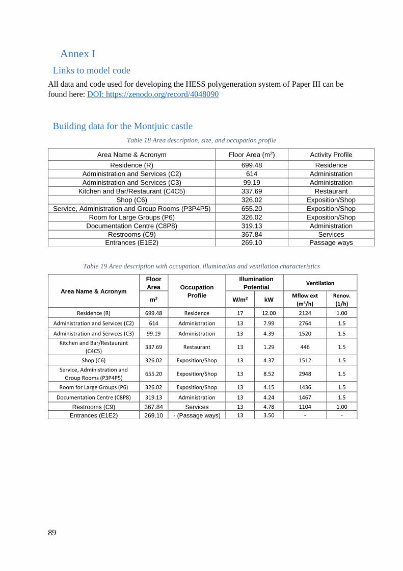
89
Annex I
Links to model code
All data and code used for developing the HESS polygeneration system of Paper III can be
found here: DOI: https://zenodo.org/record/4048090
Building data for the Montjuic castle
Table 18 Area description, size, and occupation profile
Table 19 Area description with occupation, illumination and ventilation characteristics
Area Name & Acronym Floor Area (m2) Activity Profile
Residence (R) 699.48 Residence
Administration and Services (C2) 614 Administration
Administration and Services (C3) 99.19 Administration
Kitchen and Bar/Restaurant (C4C5) 337.69 Restaurant
Shop (C6) 326.02 Exposition/Shop
Service, Administration and Group Rooms (P3P4P5) 655.20 Exposition/Shop
Room for Large Groups (P6) 326.02 Exposition/Shop
Documentation Centre (C8P8) 319.13 Administration
Restrooms (C9) 367.84 Services
Entrances (E1E2) 269.10 Passage ways
Area Name & Acronym
Floor
Area Occupation
Profile
Illumination
Potential Ventilation
m2 W/m2 kW Mflow ext
(m3/h)
Renov.
(1/h)
Residence (R) 699.48 Residence 17 12.00 2124 1.00
Administration and Services (C2) 614 Administration 13 7.99 2764 1.5
Administration and Services (C3) 99.19 Administration 13 4.39 1520 1.5
Kitchen and Bar/Restaurant
(C4C5) 337.69 Restaurant 13 1.29 446 1.5
Shop (C6) 326.02 Exposition/Shop 13 4.37 1512 1.5
Service, Administration and
Group Rooms (P3P4P5) 655.20 Exposition/Shop 13 8.52 2948 1.5
Room for Large Groups (P6) 326.02 Exposition/Shop 13 4.15 1436 1.5
Documentation Centre (C8P8) 319.13 Administration 13 4.24 1467 1.5
Restrooms (C9) 367.84 Services 13 4.78 1104 1.00
Entrances (E1E2) 269.10 - (Passage ways) 13 3.50 - -

90
Table 20 Area profiles
Areas Occupation Profile
Temperature Profile
Humidity Profile
Activity Profile Electric devices Hot Water profile* [195]
Residence Mo-So
00.00-24.00
21-25 ºC 40-60 % Seated, light work
(150 W p.p.)
Electric terminals
(80 W p.p.)
30 l/client/day
Administration Mo-Fr 09.00-
18.00
21-25 ºC 40-60 % Seated, light work
(150 W p.p.)
Electric terminals
(80 W p.p.)
5
l/employeeda
y
Restaurant Mo-Sa
10.00-23.00
21-25 ºC 40-60 % Seated eating (170W
p.p.)
Electric terminals
(80 W p.p.)
10 l/cost./day
Exposition/
Shop
Mo-So
10.00-22.00
21-25 ºC 40-60 % Standing, light work,
walking slowly (185W
p.p.)
Electric terminals
(80 W p.p.)
5 l/cost./day
Services Mo-So
08.00-22.00
18-27 ºC 40-60 % Seated, light work
(150 W p.p.)
- 5 l/cost./day
*With minimum HTW temperature = 60 ºC
Table 21 Construction element characteristics
Construction Element Building material U-Value (W/m2K) Avg. Thickness (m)
Int. Wall (Patio) Stone 2.094 0.95
Ext Wall (Patio) Stone 1.741 1.25
Ground floor (Patio) Stone 2.141 0.7
Roof (Patio) Stone, Sand, Gravel 2.094 0.95
Adj. Ceiling (Residence) Stone, concrete beams, ceramic
joining
1.549 0.24
Ext Wall (Residence) Brick, Mortar, Cement 0.541 0.5
Ground floor (Residence) Concrete 2.296 0.3
Ext. Roof - Pyramidal
(Residence)
Arabic tiles, concrete beams, ceramic
joining
1.519 0.24
Windows Aluminium frame, double-glazed 3.000 0.24
Annex II
Published Paper
Non-open access publications:

91
Paper I:
doi:10.1016/j.rser.2018.07.044.

92
Paper IV:
doi:10.1016/j.enconman.2020.113256.

93
Open-access publications: