IS300 w/ Aristo GTE Swap “Manual” - 2JZGARAGE
100
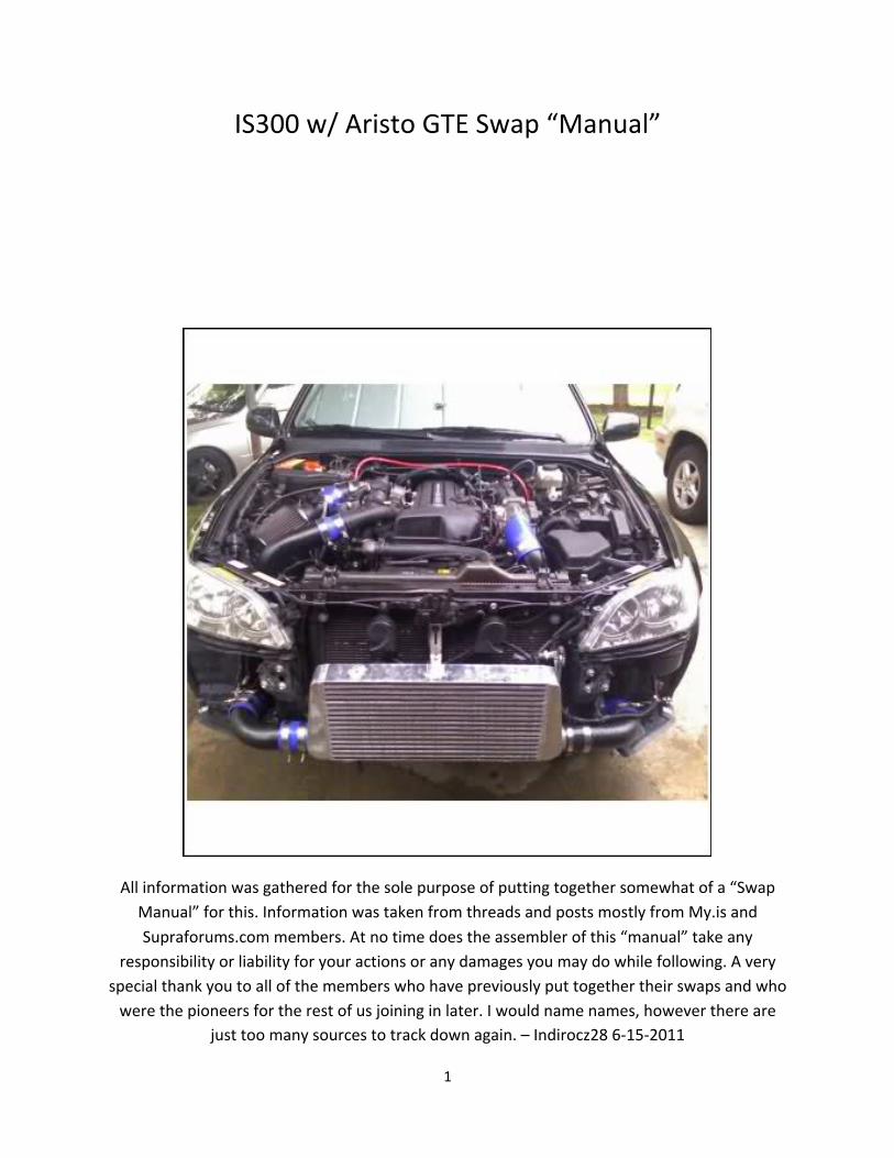
1 IS300 w/ Aristo GTE Swap “Manual” All information was gathered for the sole purpose of putting together somewhat of a “Swap Manual” for this. Information was taken from threads and posts mostly from My.is and Supraforums.com members. At no time does the assembler of this “manual” take any responsibility or liability for your actions or any damages you may do while following. A very special thank you to all of the members who have previously put together their swaps and who were the pioneers for the rest of us joining in later. I would name names, however there are just too many sources to track down again. – Indirocz28 6152011
-
Upload
khangminh22 -
Category
Documents
-
view
5 -
download
0
Transcript of IS300 w/ Aristo GTE Swap “Manual” - 2JZGARAGE
1
IS300 w/ Aristo GTE Swap “Manual”
All information was gathered for the sole purpose of putting together somewhat of a “Swap Manual” for this. Information was taken from threads and posts mostly from My.is and Supraforums.com members. At no time does the assembler of this “manual” take any
responsibility or liability for your actions or any damages you may do while following. A very special thank you to all of the members who have previously put together their swaps and who were the pioneers for the rest of us joining in later. I would name names, however there are
just too many sources to track down again. – Indirocz28 6-‐15-‐2011
2
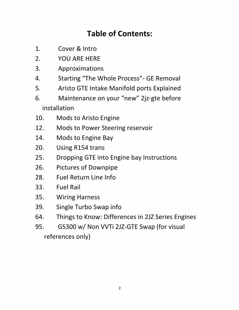
Table of Contents:
1. Cover & Intro 2. YOU ARE HERE 3. Approximations 4. Starting “The Whole Process”-‐ GE Removal 5. Aristo GTE Intake Manifold ports Explained 6. Maintenance on your “new” 2jz-‐gte before installation
10. Mods to Aristo Engine 12. Mods to Power Steering reservoir 14. Mods to Engine Bay 20. Using R154 trans 25. Dropping GTE into Engine bay Instructions 26. Pictures of Downpipe 28. Fuel Return Line Info 33. Fuel Rail 35. Wiring Harness 39. Single Turbo Swap info 64. Things to Know: Differences in 2JZ Series Engines 95. GS300 w/ Non VVTi 2JZ-‐GTE Swap (for visual
references only)
3
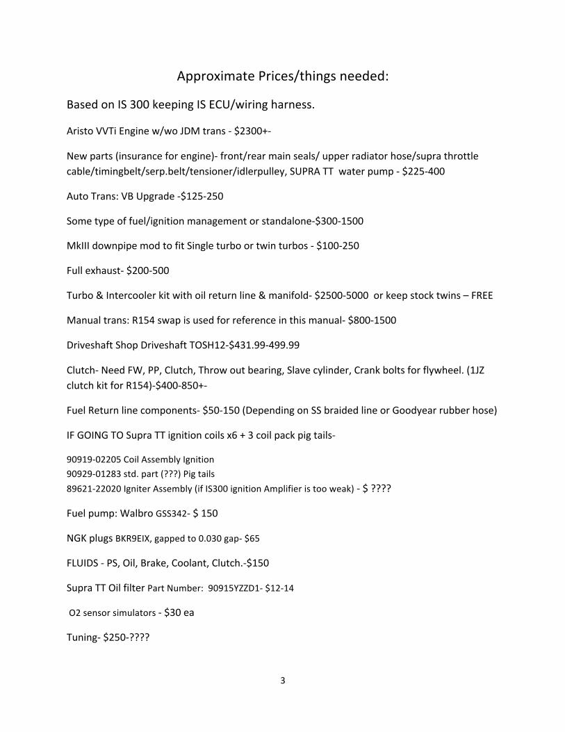
Approximate Prices/things needed:
Based on IS 300 keeping IS ECU/wiring harness.
Aristo VVTi Engine w/wo JDM trans -‐ $2300+-‐
New parts (insurance for engine)-‐ front/rear main seals/ upper radiator hose/supra throttle cable/timingbelt/serp.belt/tensioner/idlerpulley, SUPRA TT water pump -‐ $225-‐400
Auto Trans: VB Upgrade -‐$125-‐250
Some type of fuel/ignition management or standalone-‐$300-‐1500
MkIII downpipe mod to fit Single turbo or twin turbos -‐ $100-‐250
Full exhaust-‐ $200-‐500
Turbo & Intercooler kit with oil return line & manifold-‐ $2500-‐5000 or keep stock twins – FREE
Manual trans: R154 swap is used for reference in this manual-‐ $800-‐1500
Driveshaft Shop Driveshaft TOSH12-‐$431.99-‐499.99
Clutch-‐ Need FW, PP, Clutch, Throw out bearing, Slave cylinder, Crank bolts for flywheel. (1JZ clutch kit for R154)-‐$400-‐850+-‐
Fuel Return line components-‐ $50-‐150 (Depending on SS braided line or Goodyear rubber hose)
IF GOING TO Supra TT ignition coils x6 + 3 coil pack pig tails-‐
90919-‐02205 Coil Assembly Ignition
90929-‐01283 std. part (???) Pig tails
89621-‐22020 Igniter Assembly (if IS300 ignition Amplifier is too weak) -‐ $ ????
Fuel pump: Walbro GSS342-‐ $ 150
NGK plugs BKR9EIX, gapped to 0.030 gap-‐ $65
FLUIDS -‐ PS, Oil, Brake, Coolant, Clutch.-‐$150
Supra TT Oil filter Part Number: 90915YZZD1-‐ $12-‐14
O2 sensor simulators -‐ $30 ea
Tuning-‐ $250-‐????
4
Whole process (as per Wingzero’s Swap Doc):
2JZ-‐GE Removal Your first step should be to remove the engine. I will not go into detail on how to do this, because if you
have no clue how to remove an engine, DO NOT DO THIS SWAP!!! You will make a $40K paperweight. I will give you some tips on removing the engine. Start from the rear and work your way to the front.
If you feel like you won’t’ remember what is what, label them. If you don’t know what the parts are called then go buy some rolls of different colored tape and put a piece of 1 color on both ends. That way
when you’re putting it back together, you’re just matching colors, just like assembling a Dell Trust me;
it helps more than you think. (ESPECIALLY if you don’t have a TSRM) It’s beneficial to remove the upper radiator support. Makes pulling/dropping the engine a breeze.
Any bolts you remove either, screw them back in the holes so you don’t lose them or place them in a plastic zip lock bag and label them. (There will be ALOT of bolts from start to finish) Okay now that you have that done, it’s time to remove your accessories, unless you are buying new
ones. Pick-‐a-‐Part from the 2JZ-‐GE
You will need to remove the following: Power Steering Pump
A/C Compressor Alternator Starter
Water temp sensor (this is located right behind the water pump attached to the block if memory serves) And obviously the wiring harness, unless you are going to go with the Aristo harness. (LABEL EVERY
CONNECTION PLEASE!!!) Yes they should all connect in only 1 place but this will help you during the rerouting process; as you can work it around where the connections are physically. It will also help you identify what connections to extend if needed.
5
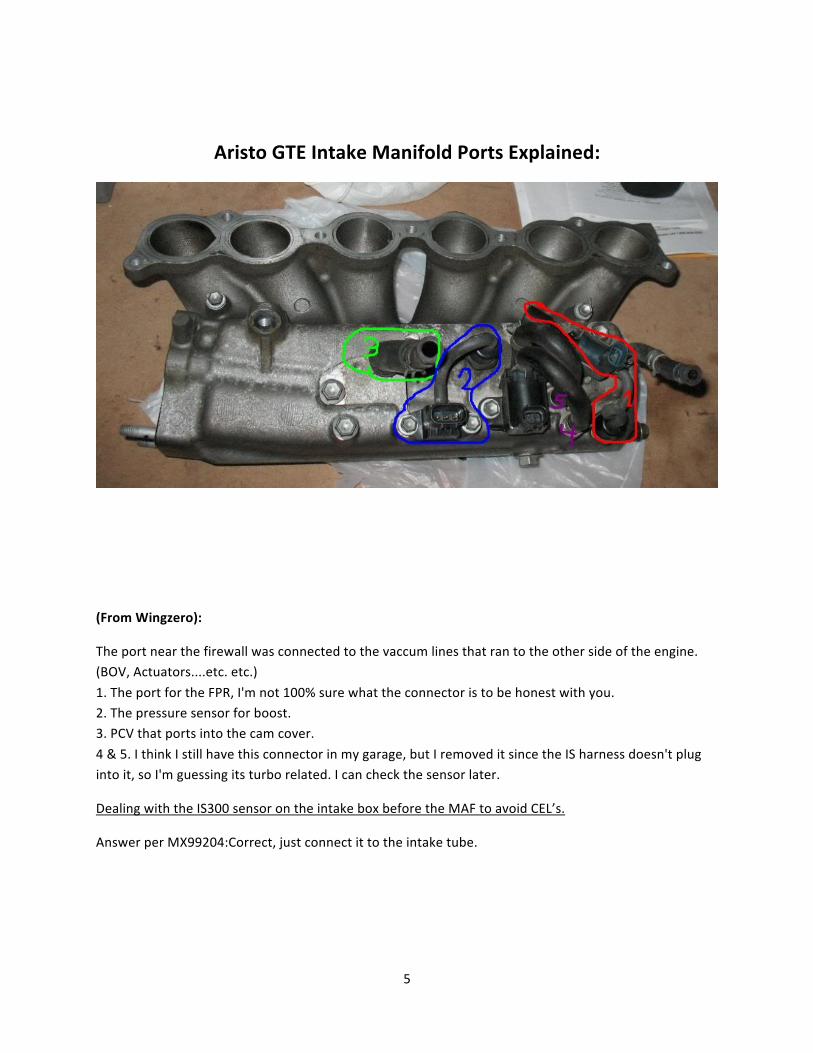
Aristo GTE Intake Manifold Ports Explained:
(From Wingzero):
The port near the firewall was connected to the vaccum lines that ran to the other side of the engine. (BOV, Actuators....etc. etc.)
1. The port for the FPR, I'm not 100% sure what the connector is to be honest with you. 2. The pressure sensor for boost. 3. PCV that ports into the cam cover.
4 & 5. I think I still have this connector in my garage, but I removed it since the IS harness doesn't plug into it, so I'm guessing its turbo related. I can check the sensor later.
Dealing with the IS300 sensor on the intake box before the MAF to avoid CEL’s.
Answer per MX99204:Correct, just connect it to the intake tube.
6
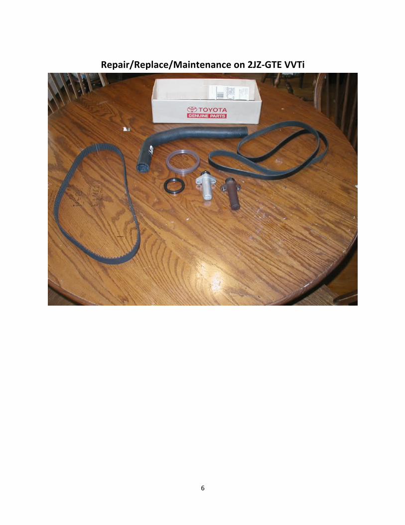
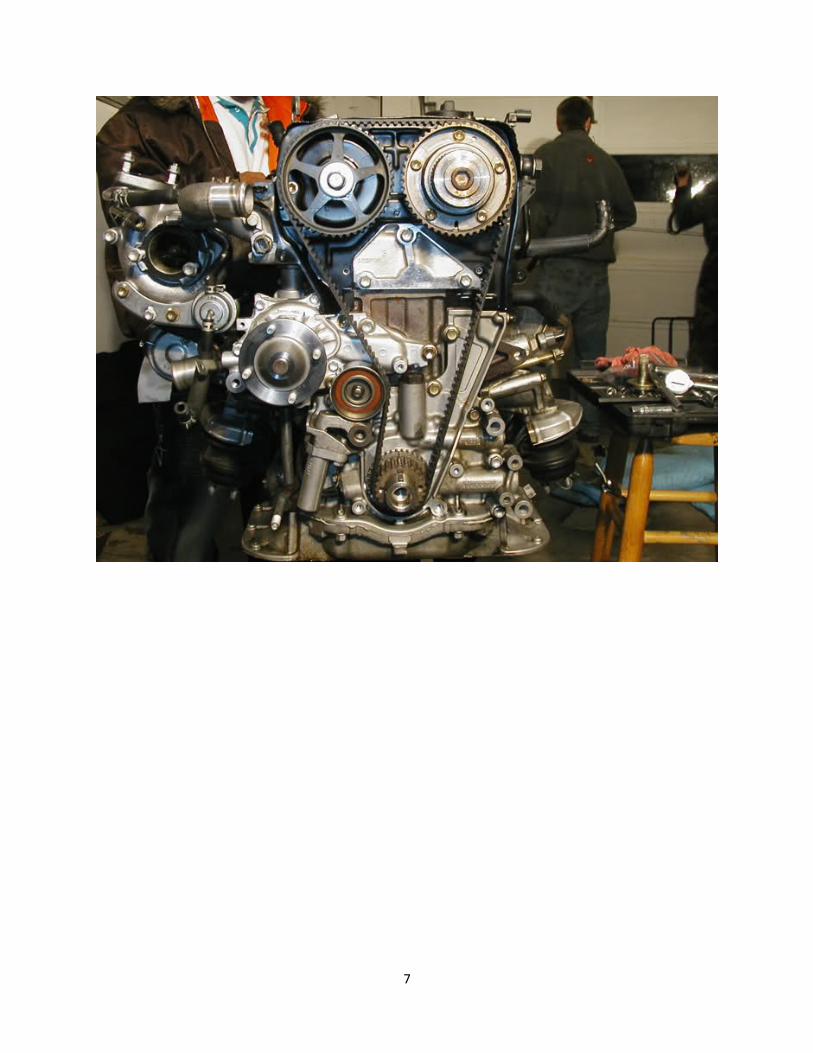
Repair/Replace/Maintenance on 2JZ-‐GTE VVTi
7
8
9
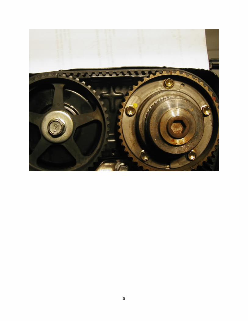
This is the PERFECT time to perform this on the new motor, BEFORE you drop it in. Things are going to
get VERY TIGHT, VERY FAST once that bad boy is dropped. Remove all the accessories you took from the GE and replace the GTE counterparts. Make sure you put
NEW gaskets, O rings, clamps, oil filter etc.
Also, do yourself a favor; buy a new timing belt and spark plugs NOW. Inspect the spark plug wires and coils. I believe you can use wires and coils from either engine as they are the same. However, it may be
beneficial to use the coils from the GE because you know they work!!
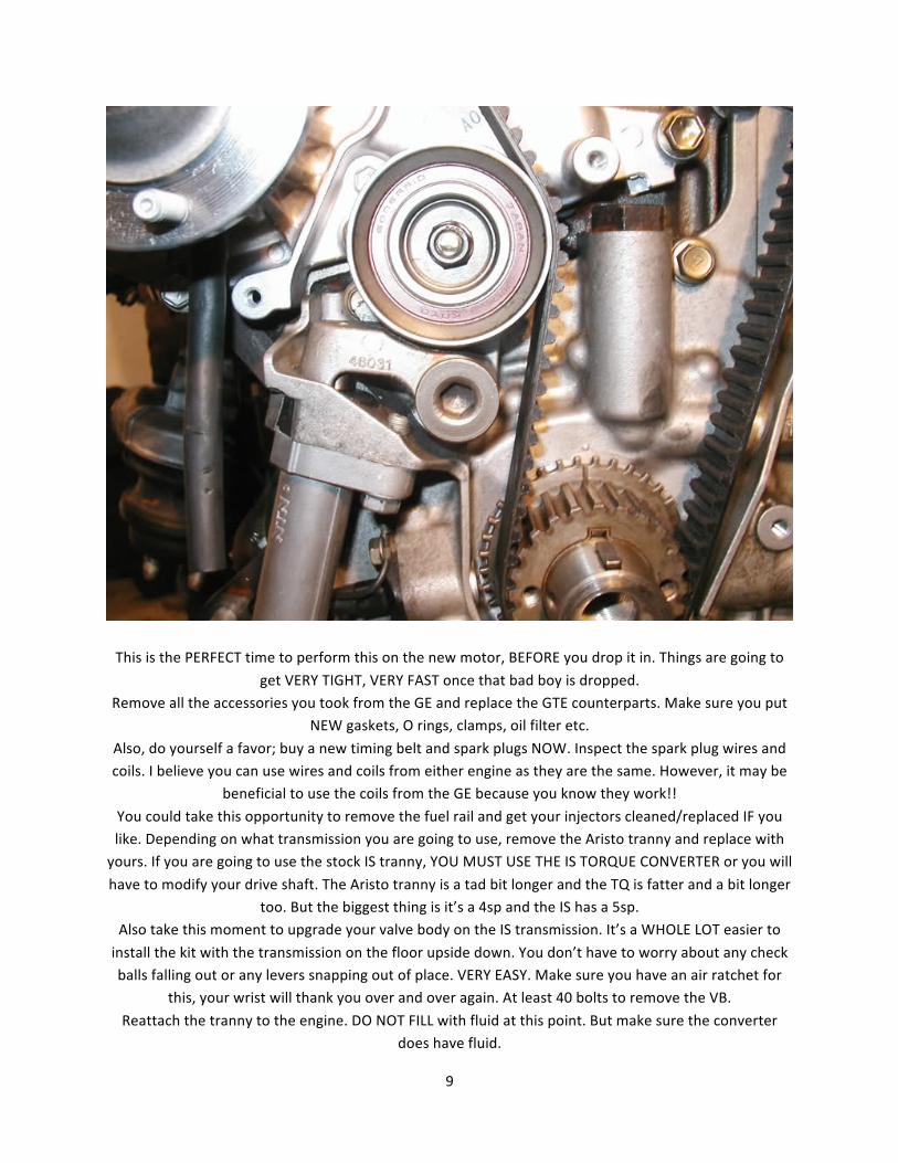
You could take this opportunity to remove the fuel rail and get your injectors cleaned/replaced IF you like. Depending on what transmission you are going to use, remove the Aristo tranny and replace with yours. If you are going to use the stock IS tranny, YOU MUST USE THE IS TORQUE CONVERTER or you will
have to modify your drive shaft. The Aristo tranny is a tad bit longer and the TQ is fatter and a bit longer too. But the biggest thing is it’s a 4sp and the IS has a 5sp.
Also take this moment to upgrade your valve body on the IS transmission. It’s a WHOLE LOT easier to
install the kit with the transmission on the floor upside down. You don’t have to worry about any check balls falling out or any levers snapping out of place. VERY EASY. Make sure you have an air ratchet for
this, your wrist will thank you over and over again. At least 40 bolts to remove the VB.
Reattach the tranny to the engine. DO NOT FILL with fluid at this point. But make sure the converter does have fluid.
10
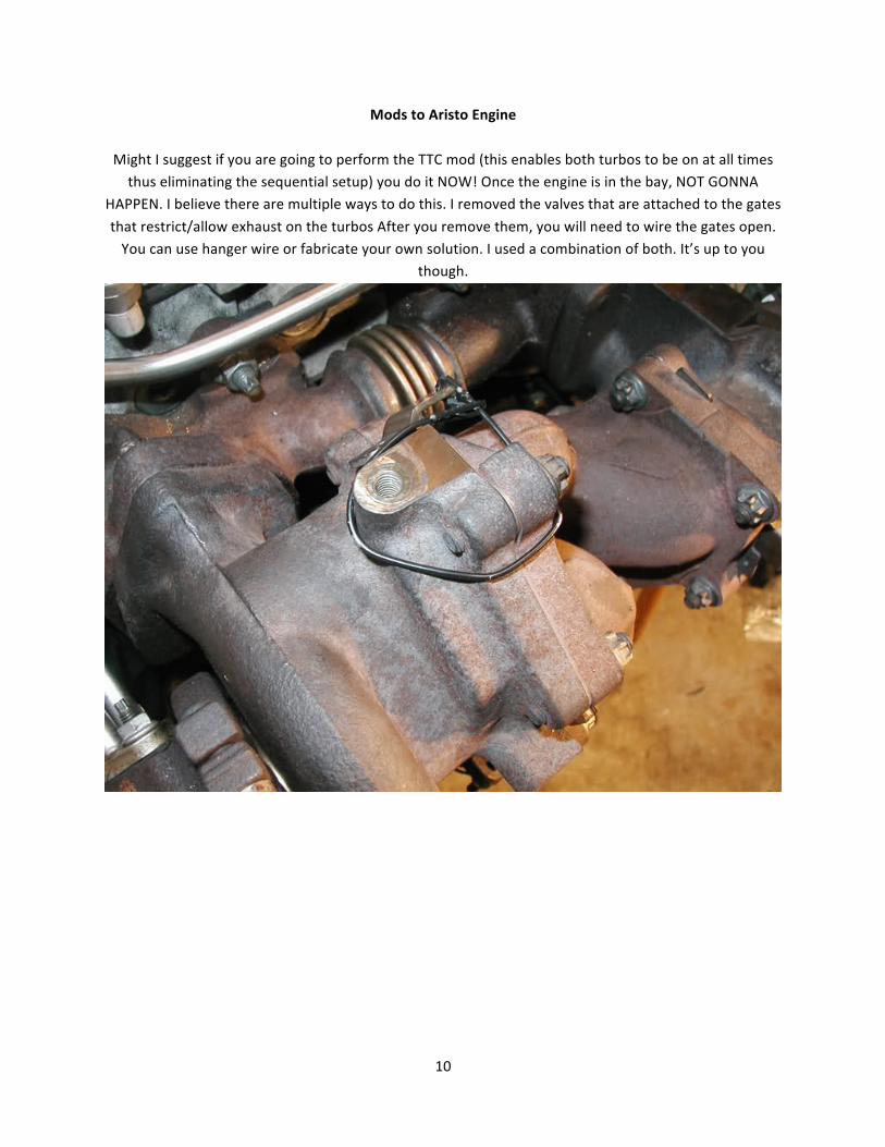
Mods to Aristo Engine
Might I suggest if you are going to perform the TTC mod (this enables both turbos to be on at all times thus eliminating the sequential setup) you do it NOW! Once the engine is in the bay, NOT GONNA
HAPPEN. I believe there are multiple ways to do this. I removed the valves that are attached to the gates
that restrict/allow exhaust on the turbos After you remove them, you will need to wire the gates open. You can use hanger wire or fabricate your own solution. I used a combination of both. It’s up to you
though.
11
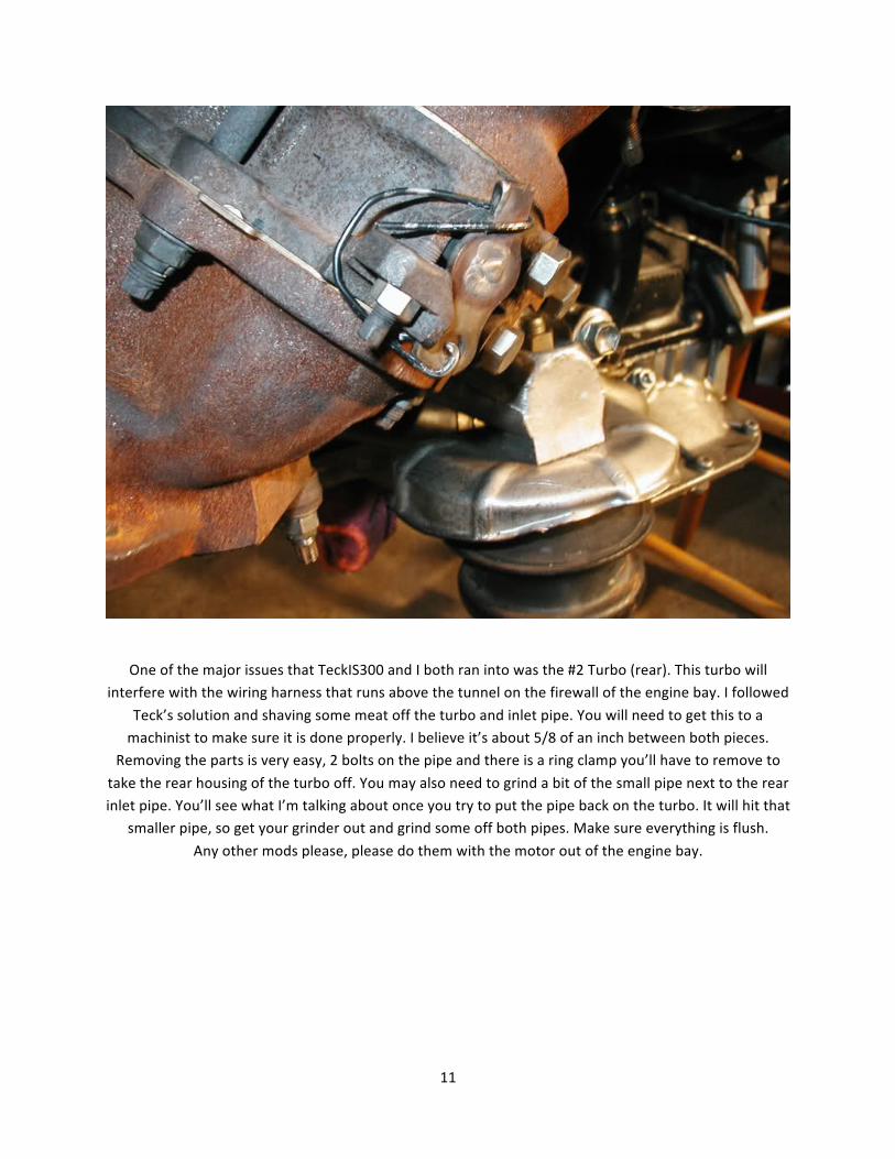
One of the major issues that TeckIS300 and I both ran into was the #2 Turbo (rear). This turbo will interfere with the wiring harness that runs above the tunnel on the firewall of the engine bay. I followed
Teck’s solution and shaving some meat off the turbo and inlet pipe. You will need to get this to a machinist to make sure it is done properly. I believe it’s about 5/8 of an inch between both pieces.
Removing the parts is very easy, 2 bolts on the pipe and there is a ring clamp you’ll have to remove to
take the rear housing of the turbo off. You may also need to grind a bit of the small pipe next to the rear inlet pipe. You’ll see what I’m talking about once you try to put the pipe back on the turbo. It will hit that
smaller pipe, so get your grinder out and grind some off both pipes. Make sure everything is flush.
Any other mods please, please do them with the motor out of the engine bay.
12
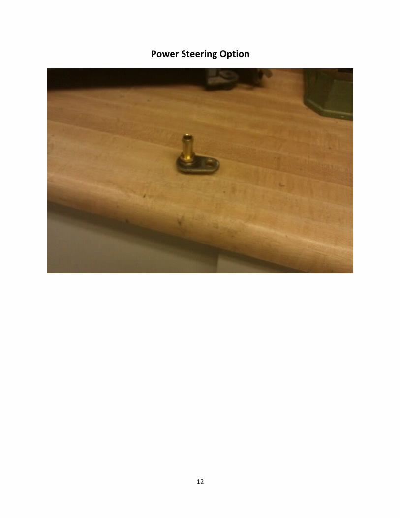
Power Steering Option
13
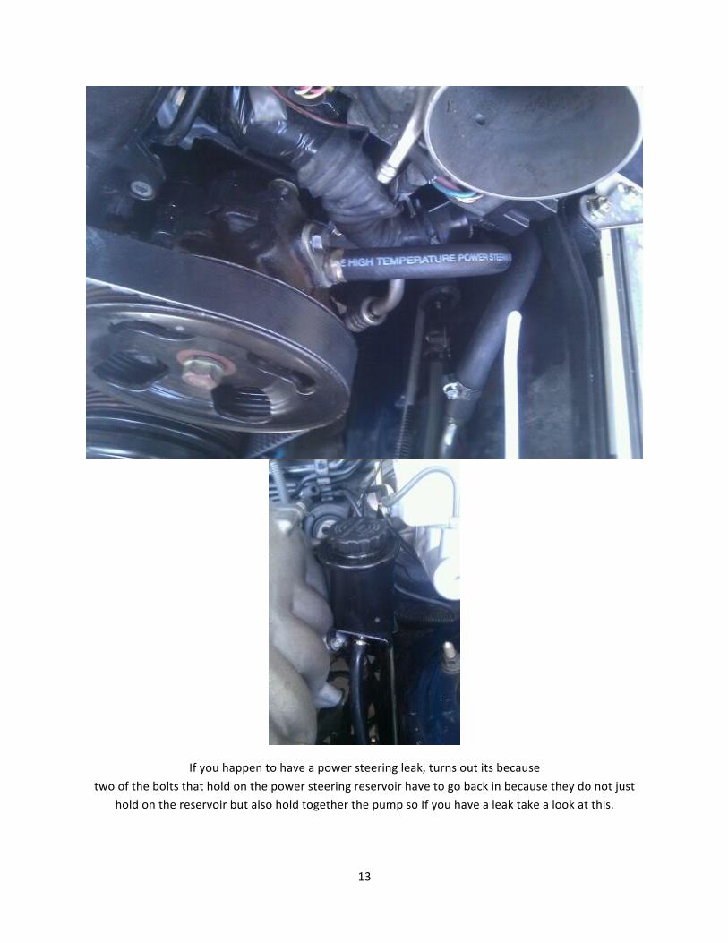
If you happen to have a power steering leak, turns out its because
two of the bolts that hold on the power steering reservoir have to go back in because they do not just hold on the reservoir but also hold together the pump so If you have a leak take a look at this.
14
Mods to IS Engine Bay
Okay, here is where the tricky stuff goes into play. These things SHOULD be done to make your ease of
dropping in the engine better and just plain old common sense. Okay here is what needs to be done.
ABS Relocation – Some have gotten it to work with just moving it slightly to the left. I went with
relocating next to the battery. This will take some time depending on how you get it done. Some can do
it with a tube bender, but the Mexicans do it with bare hands. You will need at minimum tube cutter and a flaring tool. Both are relatively cheap. Unbolt the brake lines and hoses from the ABS. You may want to plug the lines or let the fluid drain or you will have greasy, greasy hands. Modify or make a
bracket for the ABS box and set where you want it. (on battery tray) Measure the distance from the first bend along the firewall to the ABS unit itself. Add a few inches more just in case. You make want to mark what line goes where so they all go back in the same port. Get your cutter and cut the line. Now
for the flare, you can do this now or after you reshape the line, up to you. Make sure you put the bolt on the line BEFORE you start to flare it. Also if this is your first time flaring lines, practice on the piece of the line you cut off first. Don’t own yourself. At this point, start to shape the line so the end meets the port
on the ABS unit, either by hand or bending tool. Make sure you don’t do any 180 degree or sharp bends. The lines are pretty durable but why chance it. Once you’re done with that do the rest. Make sure there are no leaks on the ABS unit or you will get owned... (As per Wingzero, MX99204 and others)
15
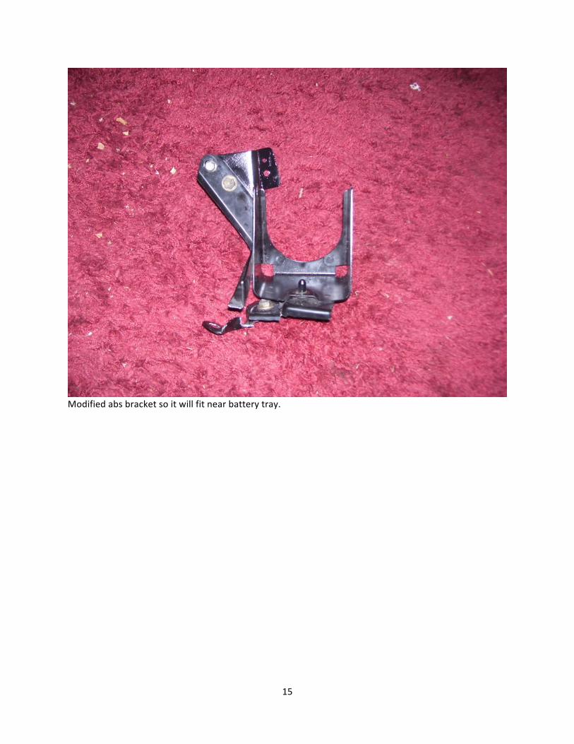
Modified abs bracket so it will fit near battery tray.
16
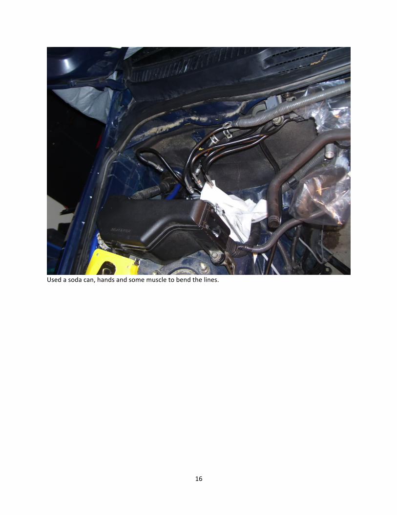
Used a soda can, hands and some muscle to bend the lines.
17
18
19
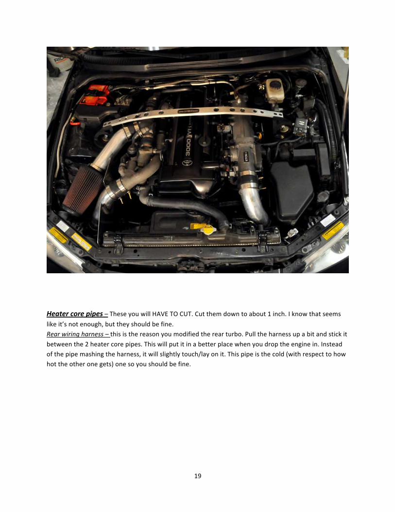
Heater core pipes – These you will HAVE TO CUT. Cut them down to about 1 inch. I know that seems
like it’s not enough, but they should be fine. Rear wiring harness – this is the reason you modified the rear turbo. Pull the harness up a bit and stick it
between the 2 heater core pipes. This will put it in a better place when you drop the engine in. Instead of the pipe mashing the harness, it will slightly touch/lay on it. This pipe is the cold (with respect to how hot the other one gets) one so you should be fine.
20
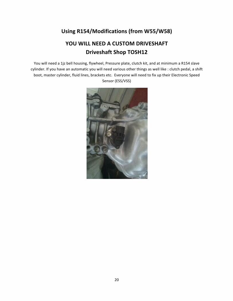
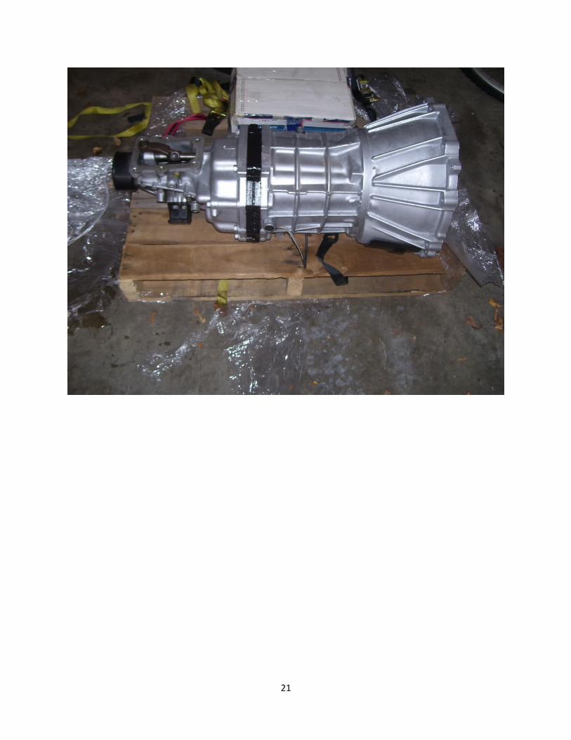
Using R154/Modifications (from W55/W58)
YOU WILL NEED A CUSTOM DRIVESHAFT Driveshaft Shop TOSH12
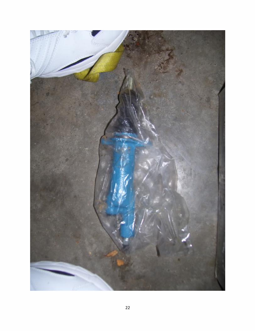
You will need a 1jz bell housing, flywheel, Pressure plate, clutch kit, and at minimum a R154 slave cylinder. If you have an automatic you will need various other things as well like : clutch pedal, a shift
boot, master cylinder, fluid lines, brackets etc. Everyone will need to fix up their Electronic Speed Sensor (ESS/VSS)
21
22
23
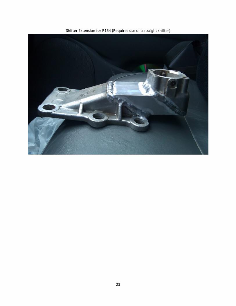
Shifter Extension for R154 (Requires use of a straight shifter)
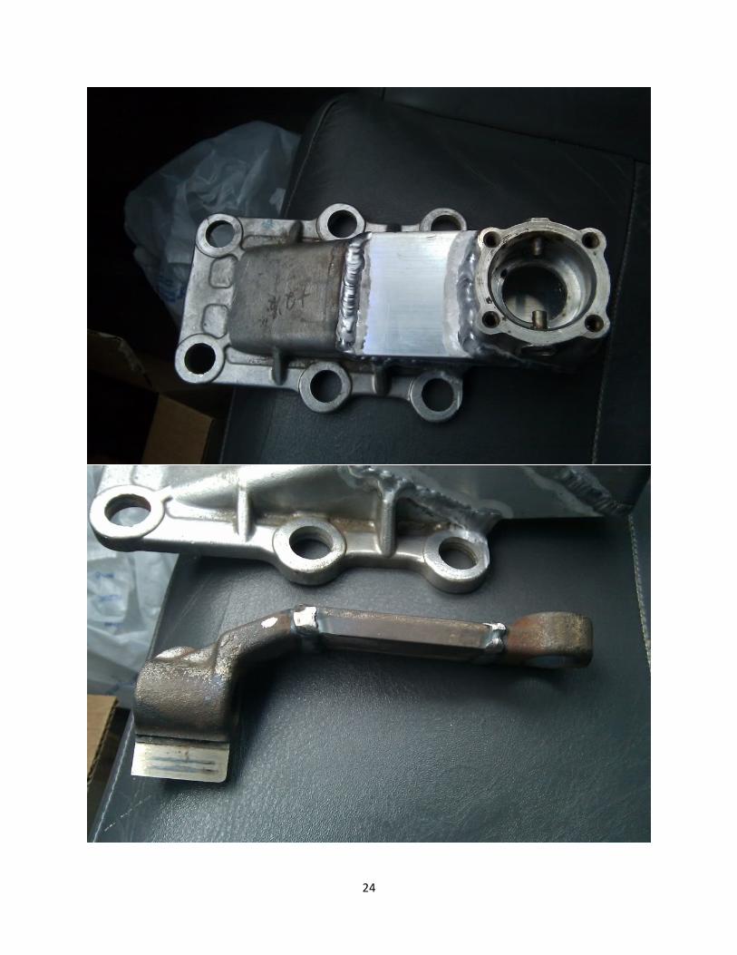
24
25
Dropping GTE Engine into the bay
Okay this part was tricky but its very doable and you WILL need at least 1 other person to do this.
1. Make sure transmission is attached and all mounts (including tranny are bolted up and ready to go. 2. Mods to ABS box, heater core pipes, and #2 Turbo housing should be done BEFORE this is attempted. 3. The wiring harness that runs along the firewall above the transmission tunnel should be un-‐buckled
and slotted between the 2 heater core pipes. (Unless you rerouted the whole thing. 4. Car should be on jack stands. (I did it with just the front raised)
5. Roll the engine/tranny in and push back as far as you can.
6. Slowly lower the engine. (You will need to use a small jack to keep the transmission where it should be and at the right angle.
7. As the engine lowers, keep pushing back.
8. The point where you stop lowering is where the bolts for the engine mounts are touching but not jaming the crossmember. They should be about 1in or so away from the holes.
9. At this point get a broom or something to flex the mounts a bit, so you can push the bolts in the holes.
You may hear a pop, that's okay, that 's the bolts poping into place (Don't push TOO hard or you may OWN your mounts, but you will have to use some muscle)
10. Once you have all 4 bolts slightly in the holes, SLOWLY lower the engine. It should level out and fall
right into place. 11. Tighten the nuts on the mounts under the car for the engine and the tranny.
12. Step back and view the marvel that is a GTE in a VERY TIGHT IS300 engine bay!
26
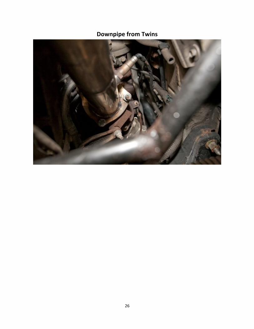
Downpipe from Twins

27
How it should look underneath
28
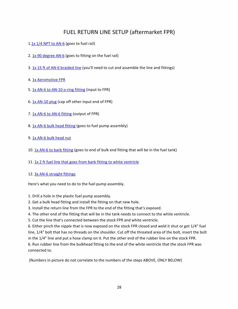
FUEL RETURN LINE SETUP (aftermarket FPR)
1.1x 1/4 NPT to AN-‐6 (goes to fuel rail)
2. 1x 90 degree AN-‐6 (goes to fitting on the fuel rail)
3. 1x 15 ft of AN-‐6 braided line (you'll need to cut and assemble the line and fittings) 4. 1x Aeromotive FPR
5. 1x AN-‐6 to AN-‐10 o-‐ring fitting (input to FPR)
6. 1x AN-‐10 plug (cap off other input end of FPR)
7. 1x AN-‐6 to AN-‐6 fitting (output of FPR) 8. 1x AN-‐6 bulk head fitting (goes to fuel pump assembly)
9. 1x AN-‐6 bulk head nut
10. 1x AN-‐6 to barb fitting (goes to end of bulk end fitting that will be in the fuel tank) 11. 1x 2 ft fuel line that goes from barb fitting to white ventricle
12. 3x AN-‐6 straight fittings
Here's what you need to do to the fuel pump assembly.
1. Drill a hole in the plastic fuel pump assembly. 2. Get a bulk head fitting and install the fitting on that new hole. 3. Install the return line from the FPR to the end of the fitting that's exposed.
4. The other end of the fitting that will be in the tank needs to connect to the white ventricle. 5. Cut the line that's connected between the stock FPR and white ventricle. 6. Either pinch the nipple that is now exposed on the stock FPR closed and weld it shut or get 1/4" fuel
line, 1/4" bolt that has no threads on the shoulder. Cut off the threated area of the bolt, insert the bolt in the 1/4" line and put a hose clamp on it. Put the other end of the rubber line on the stock FPR.
6. Run rubber line from the bulkhead fitting to the end of the white ventricle that the stock FPR was connected to.
(Numbers in picture do not correlate to the numbers of the steps ABOVE, ONLY BELOW)
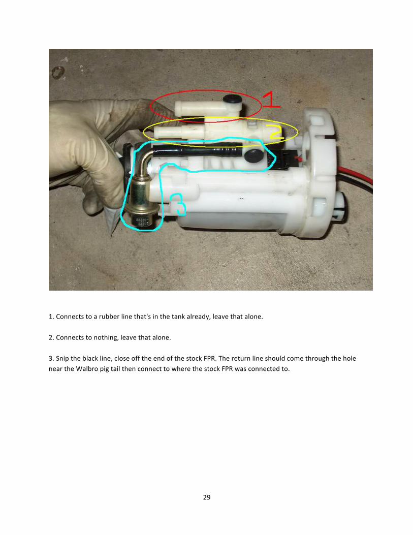
29
1. Connects to a rubber line that's in the tank already, leave that alone.
2. Connects to nothing, leave that alone.
3. Snip the black line, close off the end of the stock FPR. The return line should come through the hole near the Walbro pig tail then connect to where the stock FPR was connected to.
30
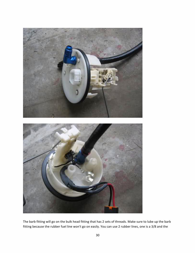
The barb fitting will go on the bulk head fitting that has 2 sets of threads. Make sure to lube up the barb fitting because the rubber fuel line won't go on easily. You can use 2 rubber lines, one is a 3/8 and the
31
other is a 5/16. The 3/8 will go on the barb fitting easier but will be lose on the plastic ventricle, you'll need to use a hose clamp to secure it. The 5/16 will be tight on the barb fitting but will be nice and snug
on the plastic ventricle. Recommended to use the 5/16.
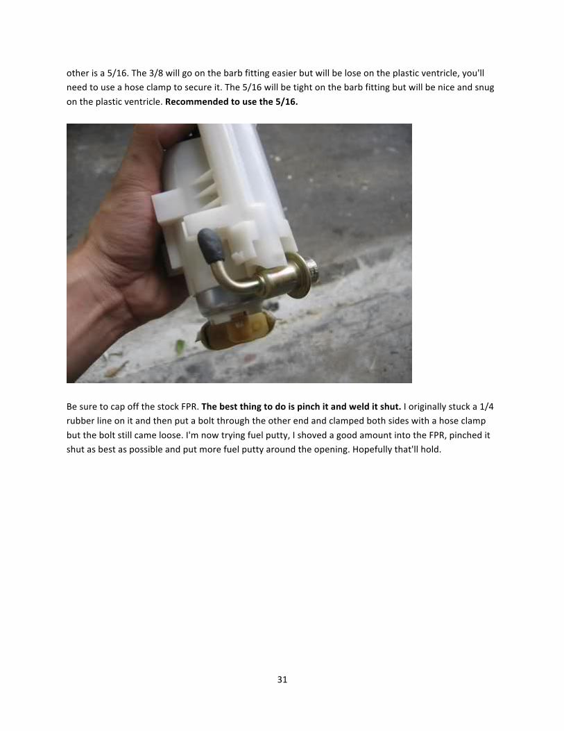
Be sure to cap off the stock FPR. The best thing to do is pinch it and weld it shut. I originally stuck a 1/4 rubber line on it and then put a bolt through the other end and clamped both sides with a hose clamp
but the bolt still came loose. I'm now trying fuel putty, I shoved a good amount into the FPR, pinched it shut as best as possible and put more fuel putty around the opening. Hopefully that'll hold.
32
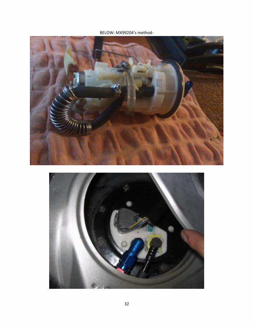
BELOW: MX99204’s method-‐
33
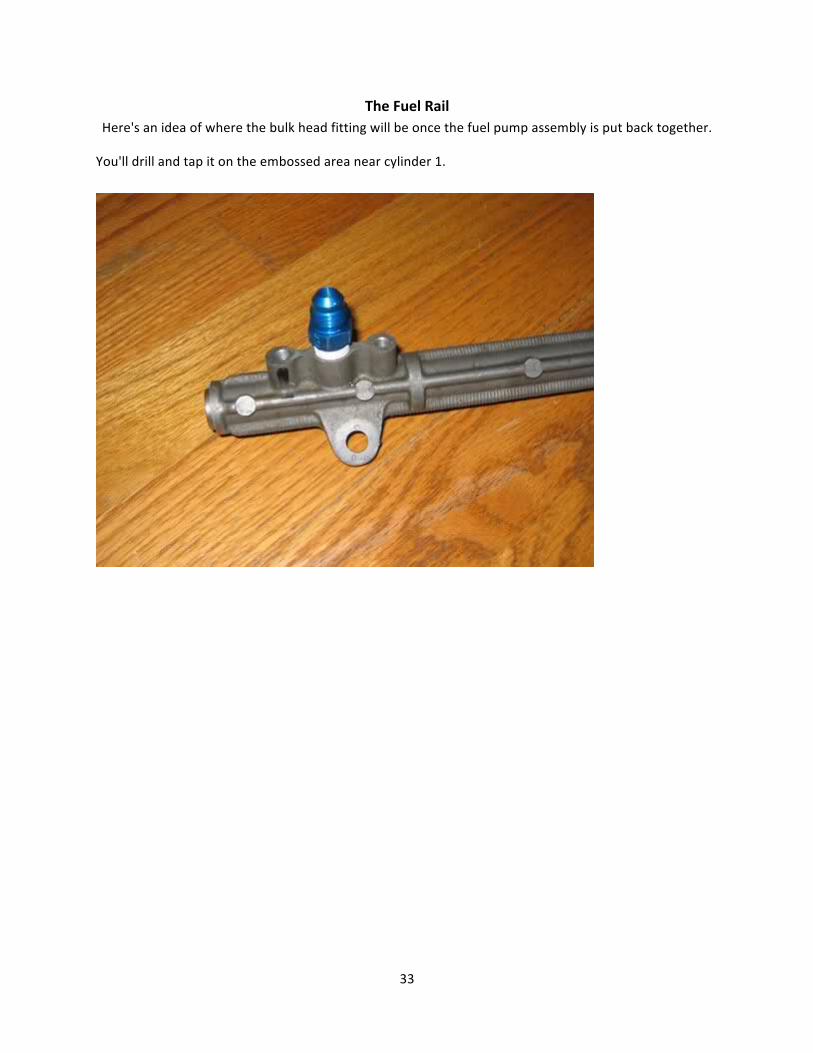
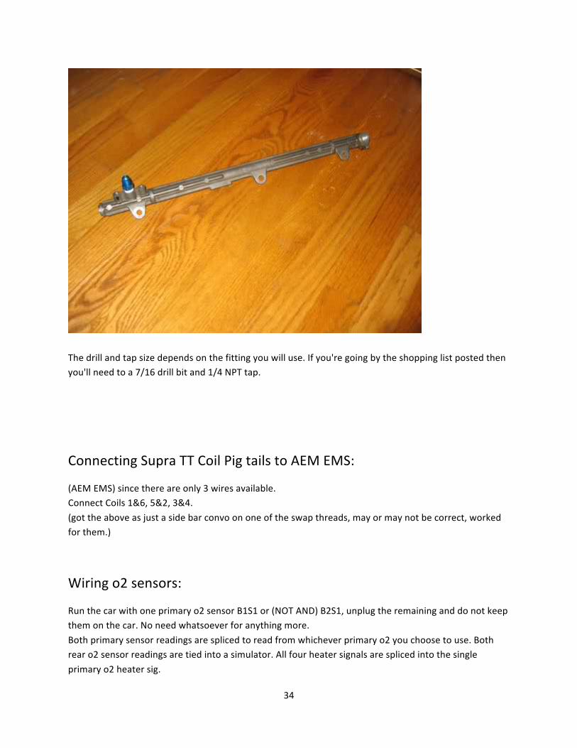
The Fuel Rail Here's an idea of where the bulk head fitting will be once the fuel pump assembly is put back together.
You'll drill and tap it on the embossed area near cylinder 1.
34
The drill and tap size depends on the fitting you will use. If you're going by the shopping list posted then you'll need to a 7/16 drill bit and 1/4 NPT tap.
Connecting Supra TT Coil Pig tails to AEM EMS:
(AEM EMS) since there are only 3 wires available. Connect Coils 1&6, 5&2, 3&4.
(got the above as just a side bar convo on one of the swap threads, may or may not be correct, worked for them.)
Wiring o2 sensors:
Run the car with one primary o2 sensor B1S1 or (NOT AND) B2S1, unplug the remaining and do not keep them on the car. No need whatsoever for anything more.
Both primary sensor readings are spliced to read from whichever primary o2 you choose to use. Both rear o2 sensor readings are tied into a simulator. All four heater signals are spliced into the single
primary o2 heater sig.
35
Rerouting Wiring Harness:
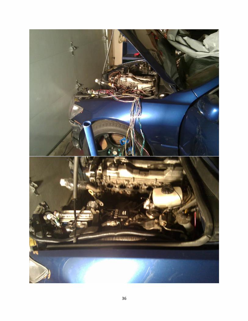
Transfer of Wiring Harness from 2JZ-‐GE VVTi to 2JZ-‐GTE VVTi You can do this many different ways. Disassemble the harness brackets/sheaths and put the other
harness in those. Completely reroute it the way you want. My method was as follows: Connect the fuel injectors and work your way around it. The IS harness can be rerouted very nicely if
done properly. TAKE YOUR TIME and GO SLOW. No need to rush, this is VERY, VERY important. Every connection on the IS harness will get used. On the other hand, every connection on the Aristo motor will NOT. This is mainly on the exhaust side. Mostly VSV’s under the #1 turbo and what not. There is also a
turbo pressure sensor that won’t get connected. I believe right under that is a valve where that is connected to the intake chamber. You may want to keep note of that. That is the nipple I used for my
BOV. But any open port will do. You can also remove any connections on the engine that you are not using. Any extra room in there is beneficial.....trust me! As for the vacuum lines, here is where you can go either way:
If your engine is complete and I mean complete than all your vacuum lines should be connected and routed properly. Then you can keep them there and use the stock BOV if you prefer. OR You can remove all the vacuum lines above the turbo’s and plug up everything. Then add the BOV of
your choice to one of the IC pipes. I used HKS SSQ. This method maybe easier and more widely used but it’s up to you.
36
37
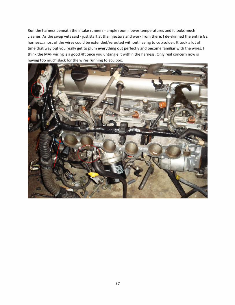
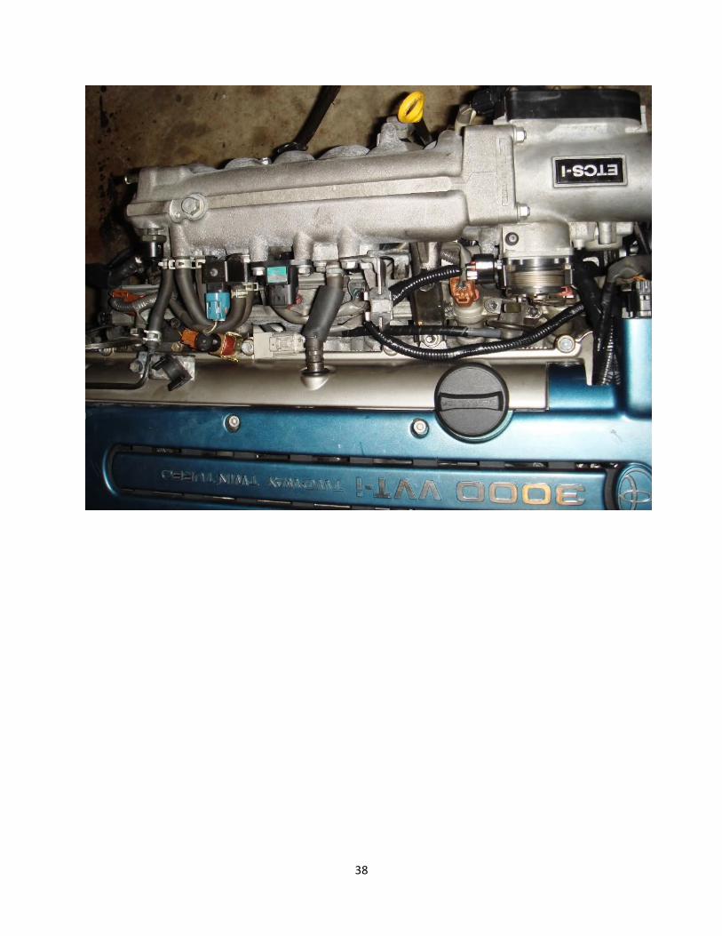
Run the harness beneath the intake runners -‐ ample room, lower temperatures and it looks much cleaner. As the swap vets said -‐ just start at the injectors and work from there. I de-‐skinned the entire GE
harness...most of the wires could be extended/rerouted without having to cut/solder. It took a lot of time that way but you really get to plum everything out perfectly and become familiar with the wires. I think the MAF wiring is a good 4ft once you untangle it within the harness. Only real concern now is
having too much slack for the wires running to ecu box.
38
39
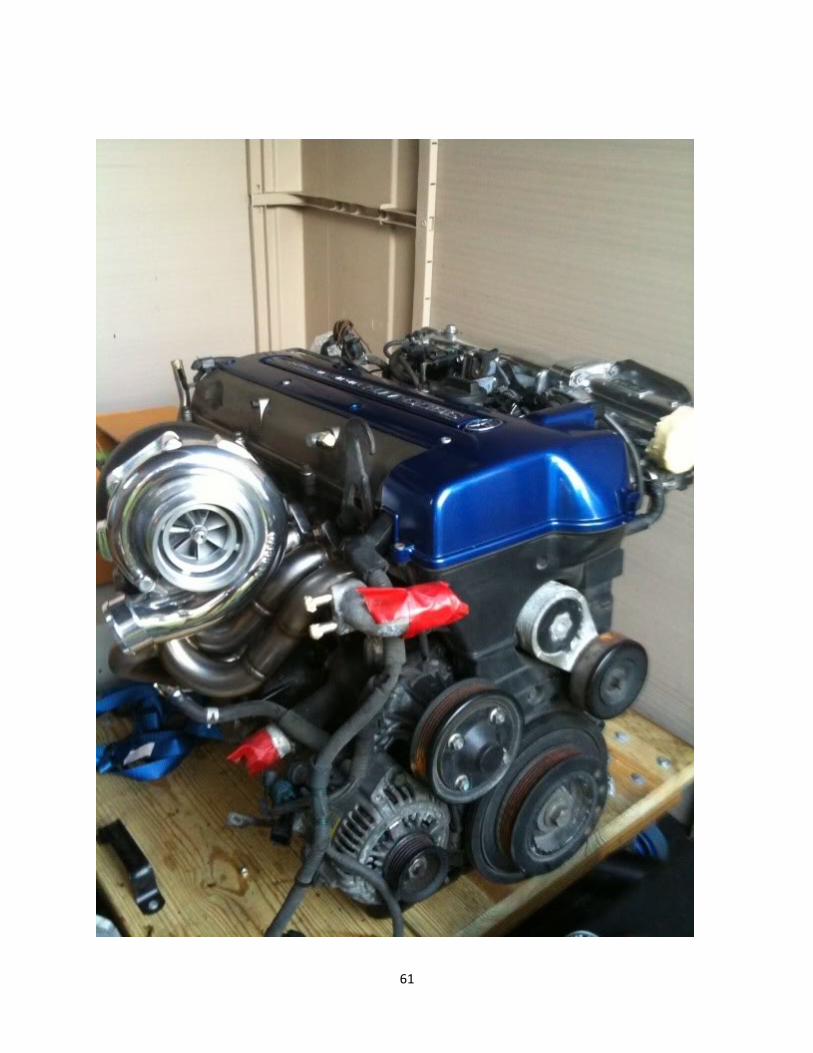
Single Turbo Setup Info/ Pictures (http://www.lexusclub.co.uk/singleturbo.htm , Andy (Bedlam) -‐ Glasgow, Scotland.
12th July 2005 – From Soarer to Supra. However, overall concept is still the same):
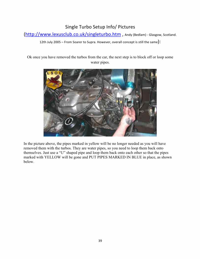
Ok once you have removed the turbos from the car, the next step is to block off or loop some water pipes.
In the picture above, the pipes marked in yellow will be no longer needed as you will have removed them with the turbos. They are water pipes, so you need to loop them back onto themselves. Just use a “U” shaped pipe and loop them back onto each other so that the pipes marked with YELLOW will be gone and PUT PIPES MARKED IN BLUE in place, as shown below.
40
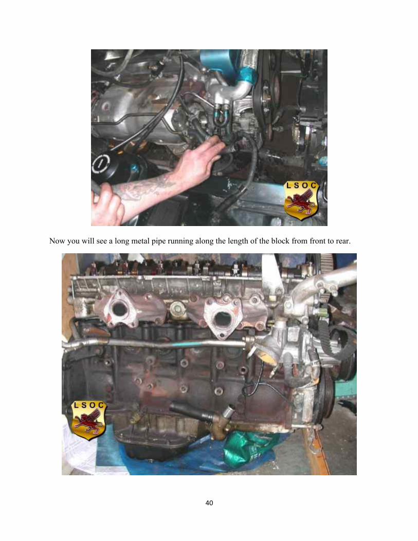
Now you will see a long metal pipe running along the length of the block from front to rear.
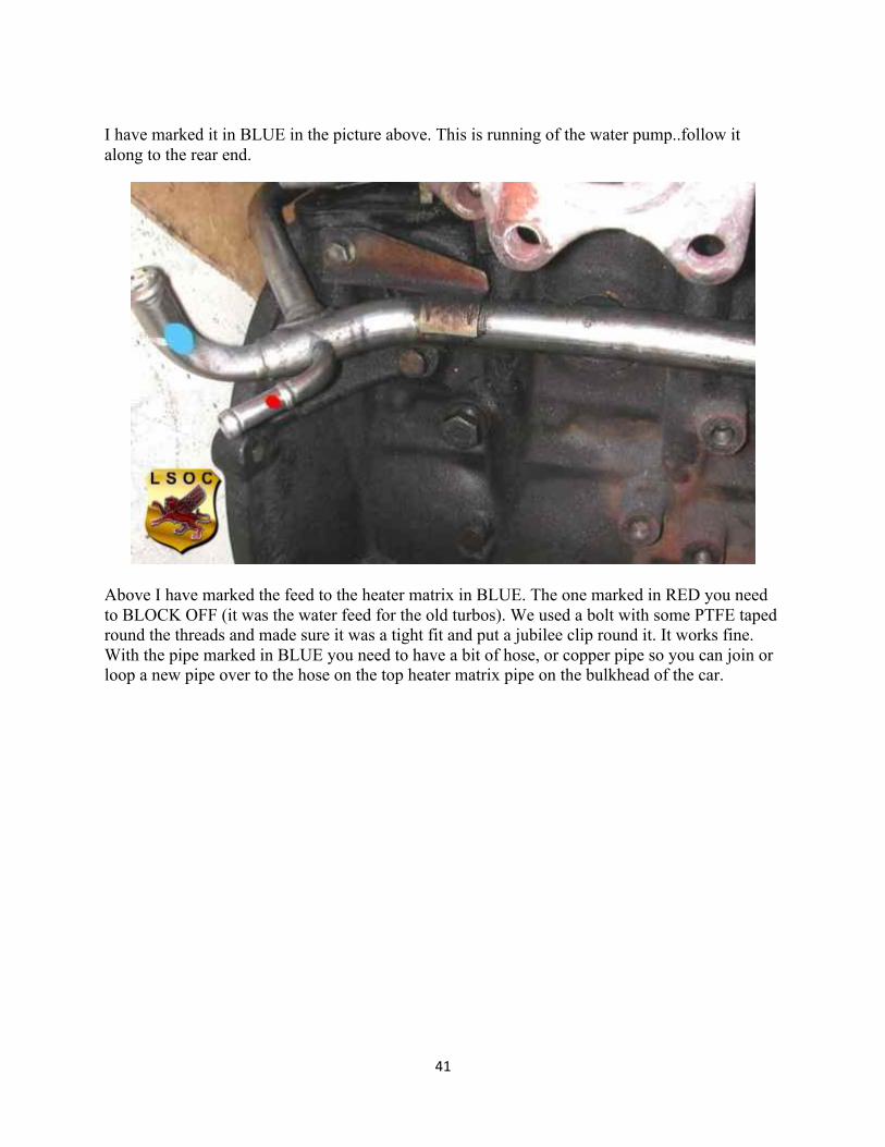
41
I have marked it in BLUE in the picture above. This is running of the water pump..follow it along to the rear end.
Above I have marked the feed to the heater matrix in BLUE. The one marked in RED you need to BLOCK OFF (it was the water feed for the old turbos). We used a bolt with some PTFE taped round the threads and made sure it was a tight fit and put a jubilee clip round it. It works fine. With the pipe marked in BLUE you need to have a bit of hose, or copper pipe so you can join or loop a new pipe over to the hose on the top heater matrix pipe on the bulkhead of the car.
42
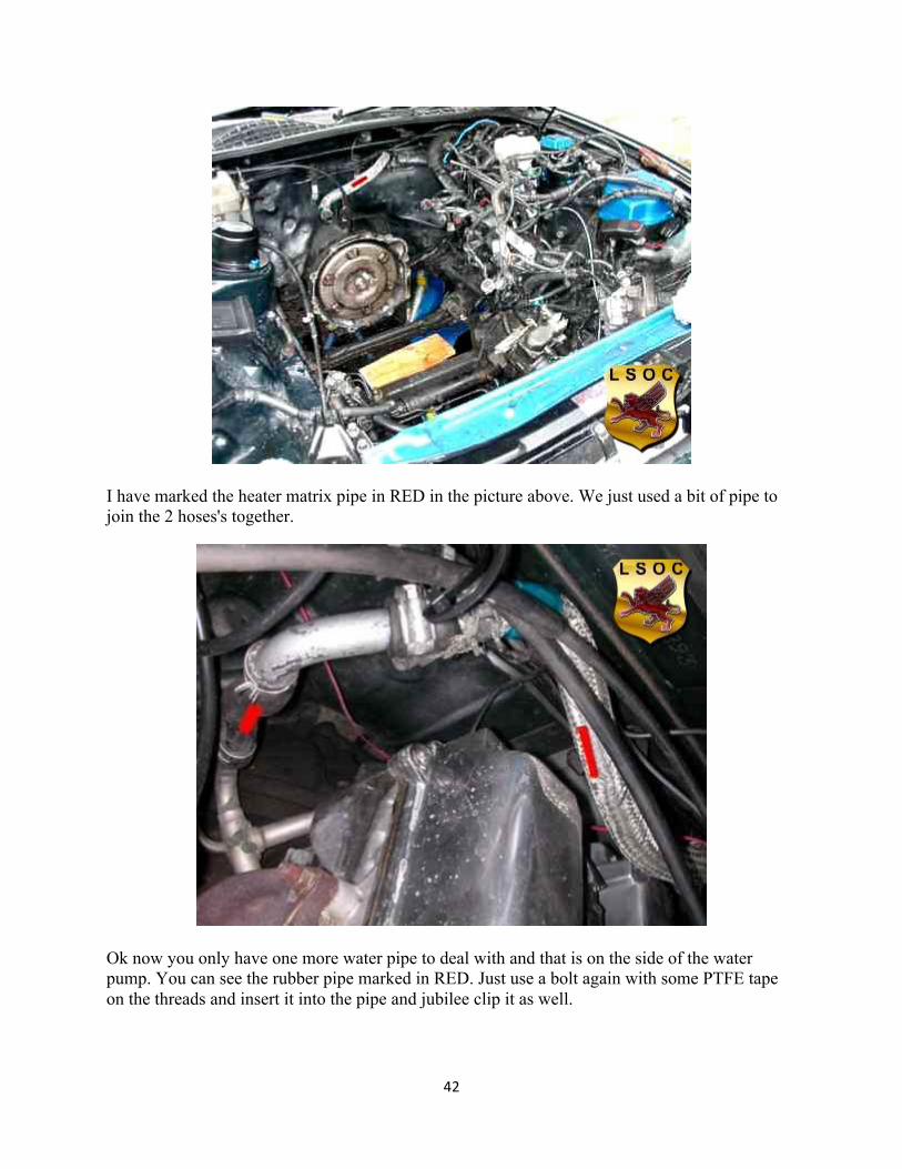
I have marked the heater matrix pipe in RED in the picture above. We just used a bit of pipe to join the 2 hoses's together.
Ok now you only have one more water pipe to deal with and that is on the side of the water pump. You can see the rubber pipe marked in RED. Just use a bolt again with some PTFE tape on the threads and insert it into the pipe and jubilee clip it as well.
43
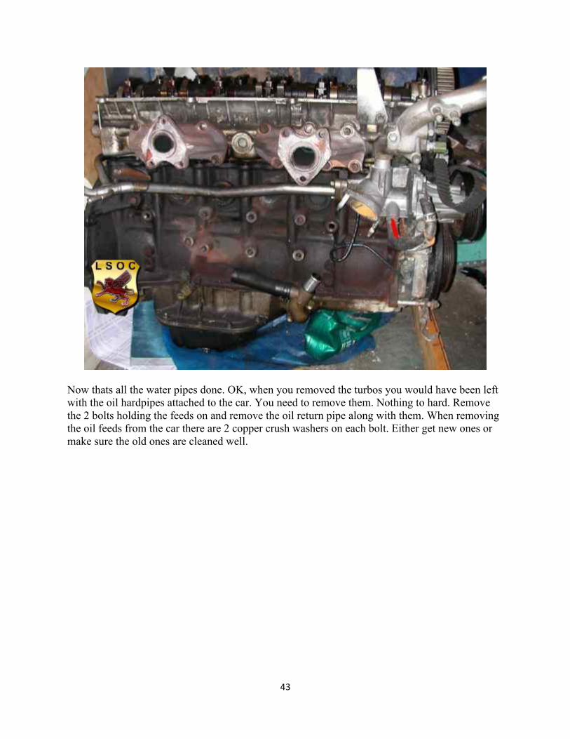
Now thats all the water pipes done. OK, when you removed the turbos you would have been left with the oil hardpipes attached to the car. You need to remove them. Nothing to hard. Remove the 2 bolts holding the feeds on and remove the oil return pipe along with them. When removing the oil feeds from the car there are 2 copper crush washers on each bolt. Either get new ones or make sure the old ones are cleaned well.
44
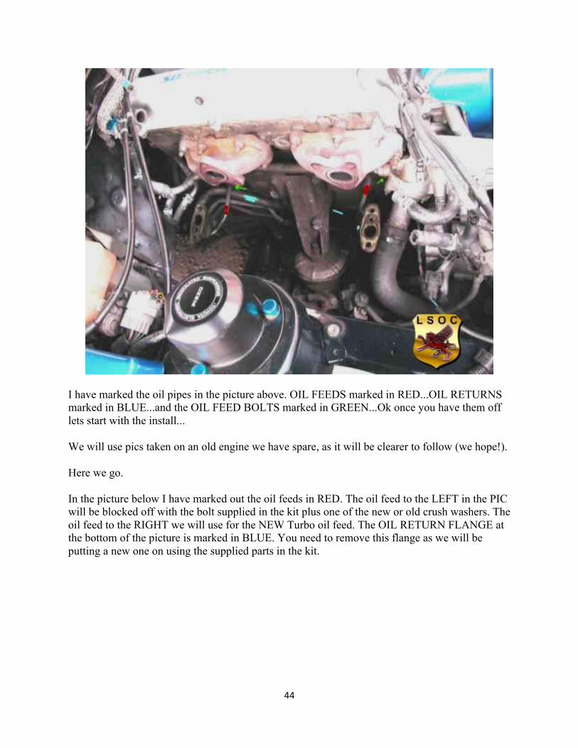
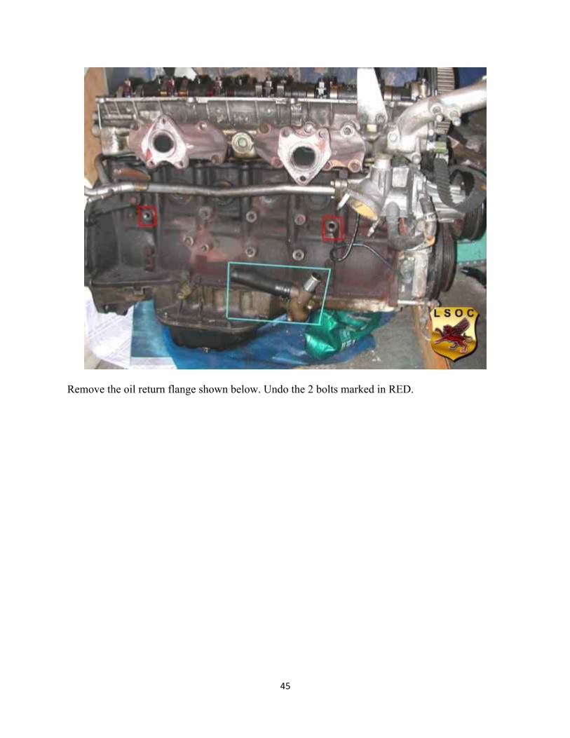
I have marked the oil pipes in the picture above. OIL FEEDS marked in RED...OIL RETURNS marked in BLUE...and the OIL FEED BOLTS marked in GREEN...Ok once you have them off lets start with the install... We will use pics taken on an old engine we have spare, as it will be clearer to follow (we hope!). Here we go. In the picture below I have marked out the oil feeds in RED. The oil feed to the LEFT in the PIC will be blocked off with the bolt supplied in the kit plus one of the new or old crush washers. The oil feed to the RIGHT we will use for the NEW Turbo oil feed. The OIL RETURN FLANGE at the bottom of the picture is marked in BLUE. You need to remove this flange as we will be putting a new one on using the supplied parts in the kit.
45
Remove the oil return flange shown below. Undo the 2 bolts marked in RED.
46
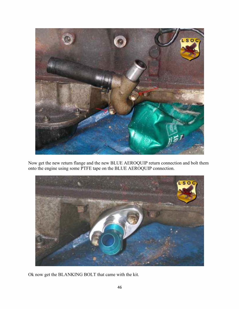
Now get the new return flange and the new BLUE AEROQUIP return connection and bolt them onto the engine using some PTFE tape on the BLUE AEROQUIP connection.
Ok now get the BLANKING BOLT that came with the kit.
47
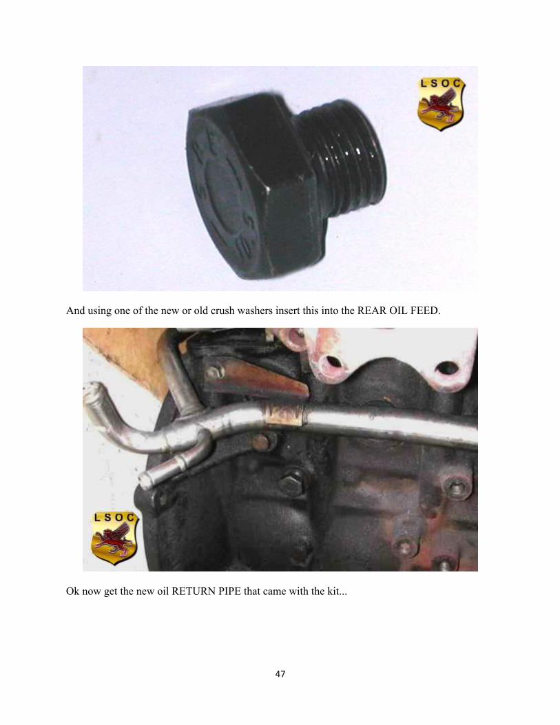
And using one of the new or old crush washers insert this into the REAR OIL FEED.
Ok now get the new oil RETURN PIPE that came with the kit...
48
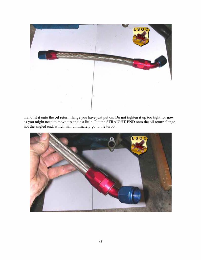
...and fit it onto the oil return flange you have just put on. Do not tighten it up too tight for now as you might need to move it's angle a little. Put the STRAIGHT END onto the oil return flange not the angled end, which will unltimately go to the turbo.
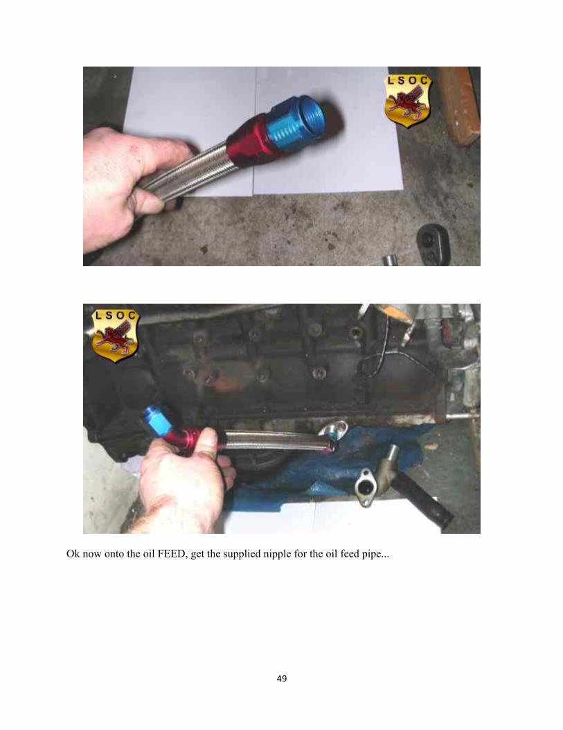
49
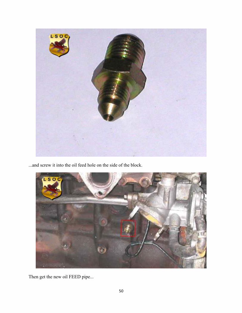
Ok now onto the oil FEED, get the supplied nipple for the oil feed pipe...
50
...and screw it into the oil feed hole on the side of the block.
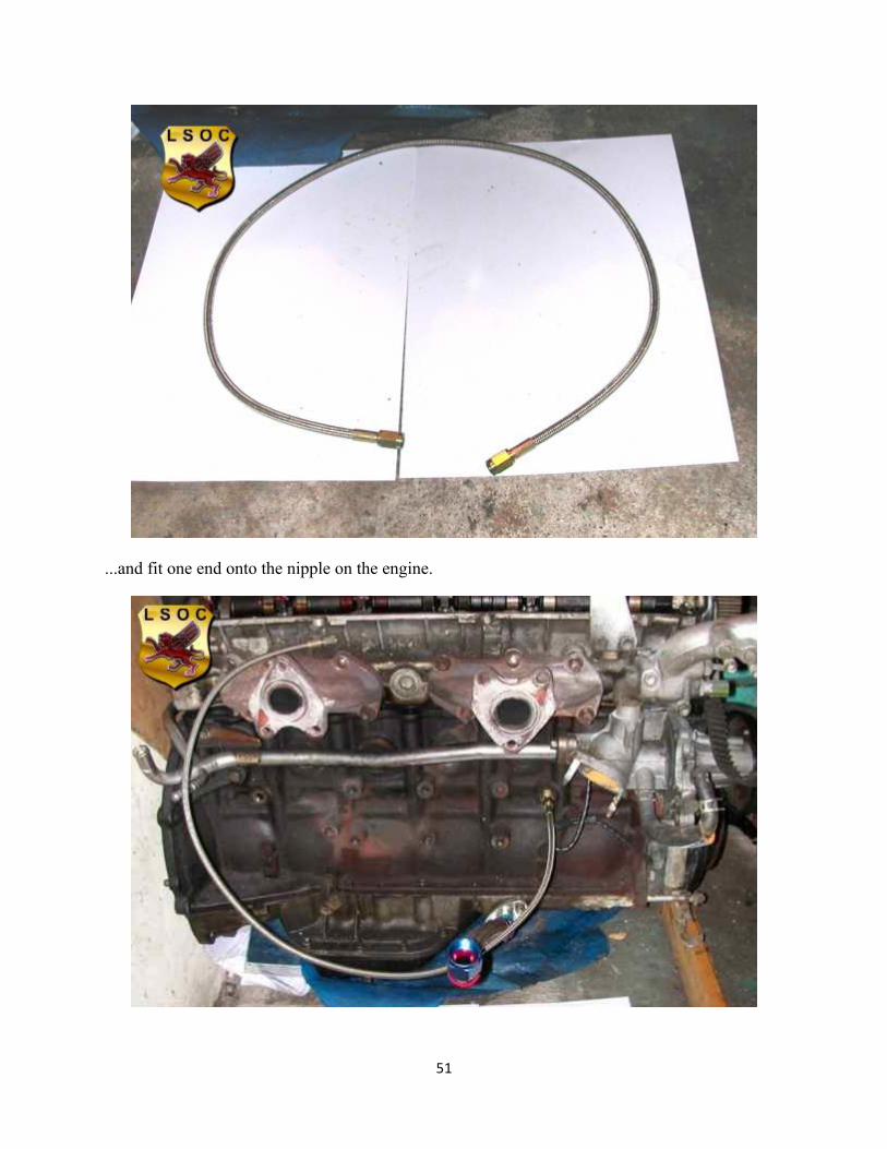
Then get the new oil FEED pipe...
51
...and fit one end onto the nipple on the engine.
52
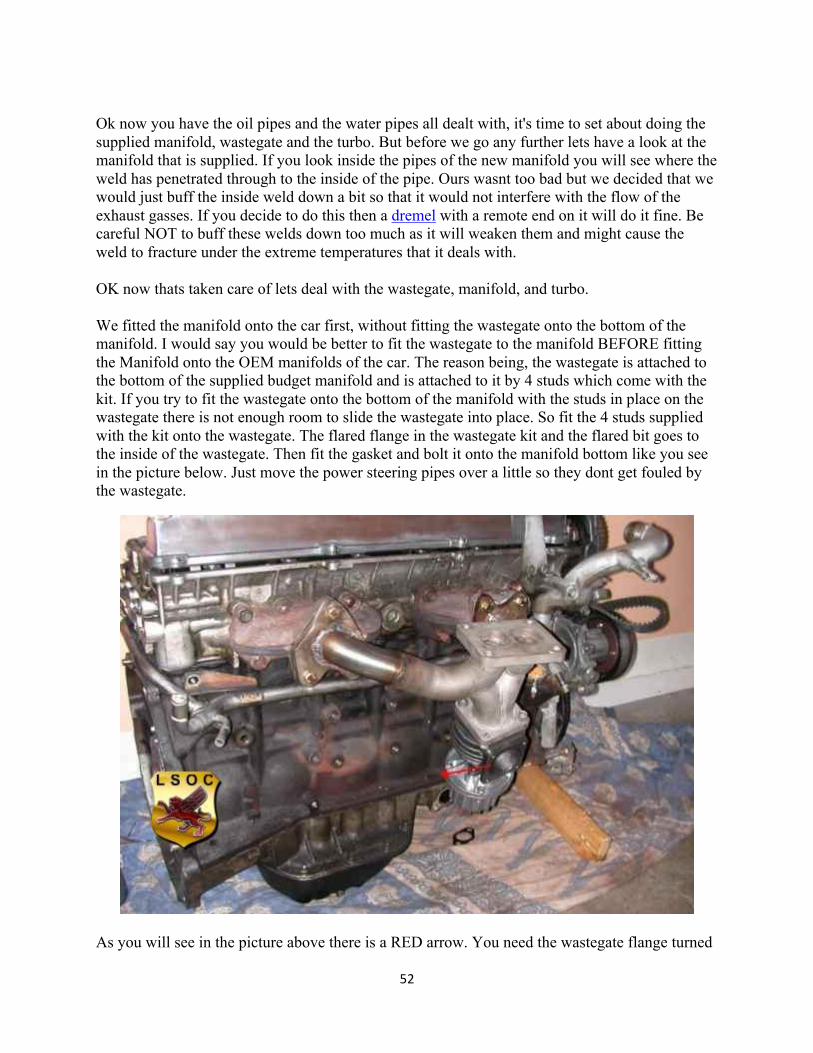
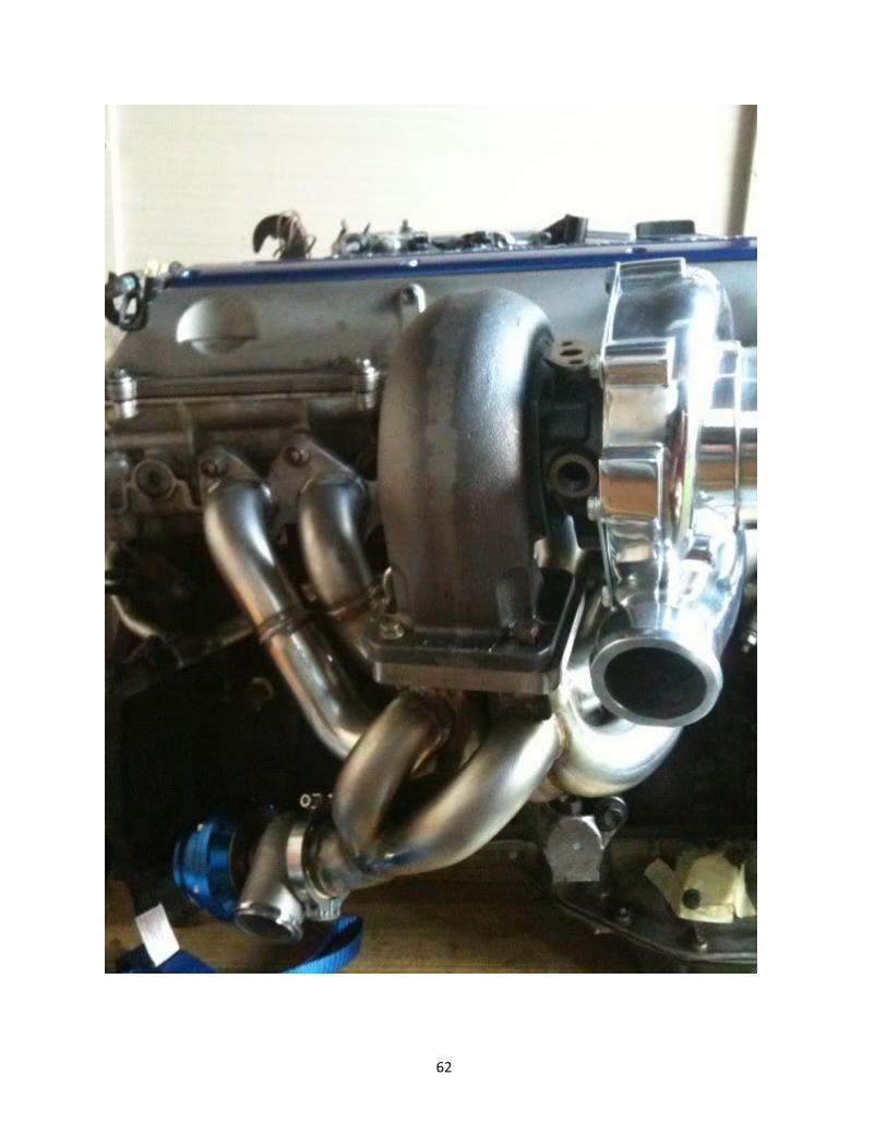
Ok now you have the oil pipes and the water pipes all dealt with, it's time to set about doing the supplied manifold, wastegate and the turbo. But before we go any further lets have a look at the manifold that is supplied. If you look inside the pipes of the new manifold you will see where the weld has penetrated through to the inside of the pipe. Ours wasnt too bad but we decided that we would just buff the inside weld down a bit so that it would not interfere with the flow of the exhaust gasses. If you decide to do this then a dremel with a remote end on it will do it fine. Be careful NOT to buff these welds down too much as it will weaken them and might cause the weld to fracture under the extreme temperatures that it deals with. OK now thats taken care of lets deal with the wastegate, manifold, and turbo. We fitted the manifold onto the car first, without fitting the wastegate onto the bottom of the manifold. I would say you would be better to fit the wastegate to the manifold BEFORE fitting the Manifold onto the OEM manifolds of the car. The reason being, the wastegate is attached to the bottom of the supplied budget manifold and is attached to it by 4 studs which come with the kit. If you try to fit the wastegate onto the bottom of the manifold with the studs in place on the wastegate there is not enough room to slide the wastegate into place. So fit the 4 studs supplied with the kit onto the wastegate. The flared flange in the wastegate kit and the flared bit goes to the inside of the wastegate. Then fit the gasket and bolt it onto the manifold bottom like you see in the picture below. Just move the power steering pipes over a little so they dont get fouled by the wastegate.
As you will see in the picture above there is a RED arrow. You need the wastegate flange turned
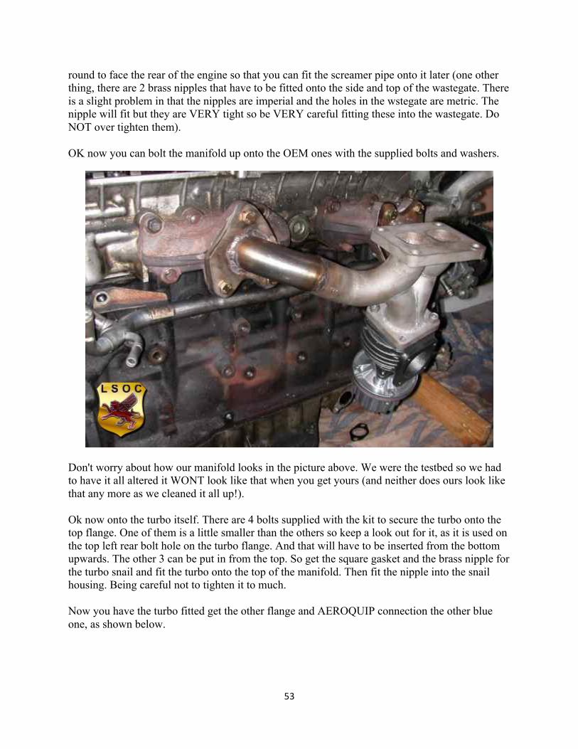
53
round to face the rear of the engine so that you can fit the screamer pipe onto it later (one other thing, there are 2 brass nipples that have to be fitted onto the side and top of the wastegate. There is a slight problem in that the nipples are imperial and the holes in the wstegate are metric. The nipple will fit but they are VERY tight so be VERY careful fitting these into the wastegate. Do NOT over tighten them). OK now you can bolt the manifold up onto the OEM ones with the supplied bolts and washers.
Don't worry about how our manifold looks in the picture above. We were the testbed so we had to have it all altered it WONT look like that when you get yours (and neither does ours look like that any more as we cleaned it all up!). Ok now onto the turbo itself. There are 4 bolts supplied with the kit to secure the turbo onto the top flange. One of them is a little smaller than the others so keep a look out for it, as it is used on the top left rear bolt hole on the turbo flange. And that will have to be inserted from the bottom upwards. The other 3 can be put in from the top. So get the square gasket and the brass nipple for the turbo snail and fit the turbo onto the top of the manifold. Then fit the nipple into the snail housing. Being careful not to tighten it to much. Now you have the turbo fitted get the other flange and AEROQUIP connection the other blue one, as shown below.
54
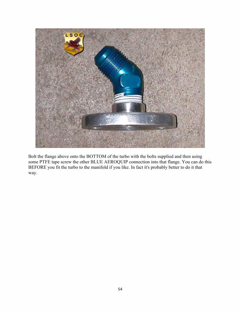
Bolt the flange above onto the BOTTOM of the turbo with the bolts supplied and then using some PTFE tape screw the other BLUE AEROQUIP connection into that flange. You can do this BEFORE you fit the turbo to the manifold if you like. In fact it's probably better to do it that way.
55
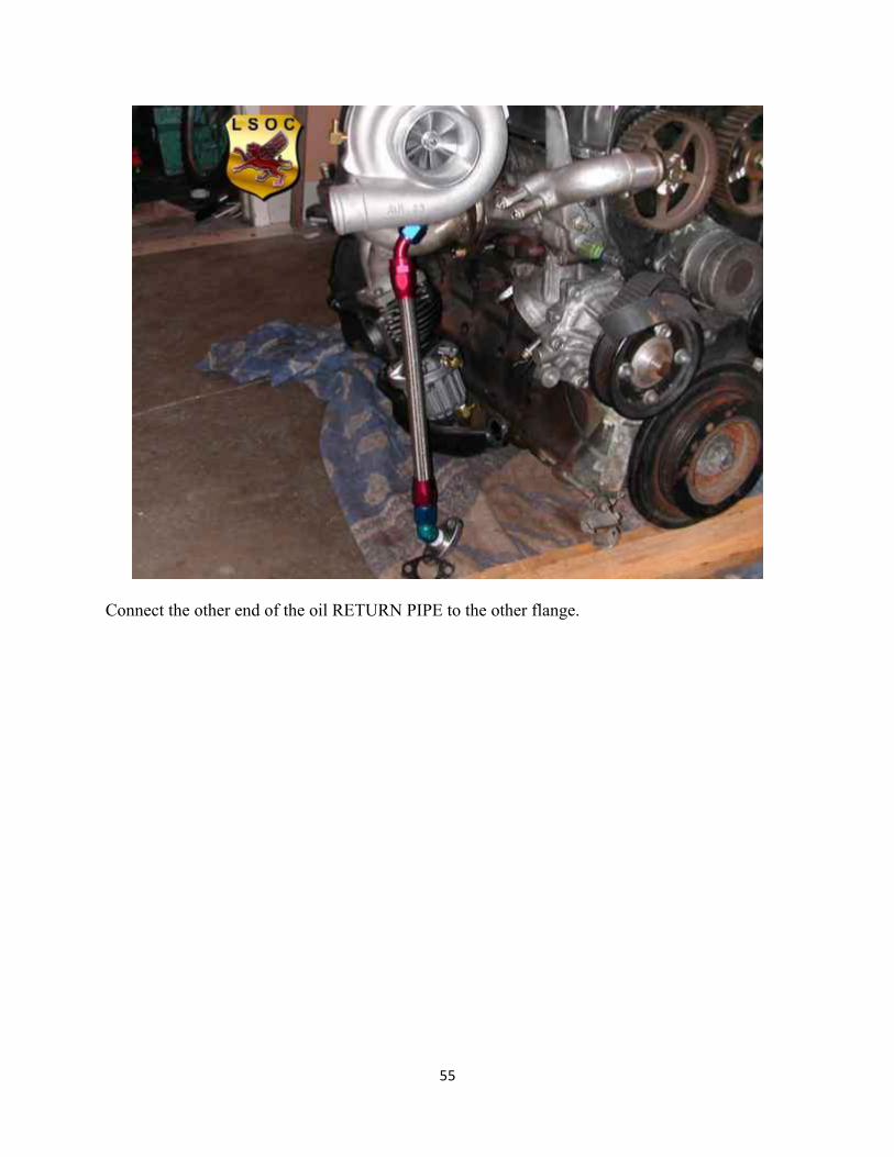
Connect the other end of the oil RETURN PIPE to the other flange.
56
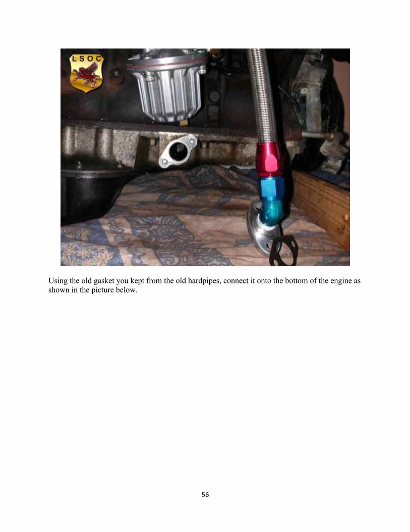
Using the old gasket you kept from the old hardpipes, connect it onto the bottom of the engine as shown in the picture below.
57
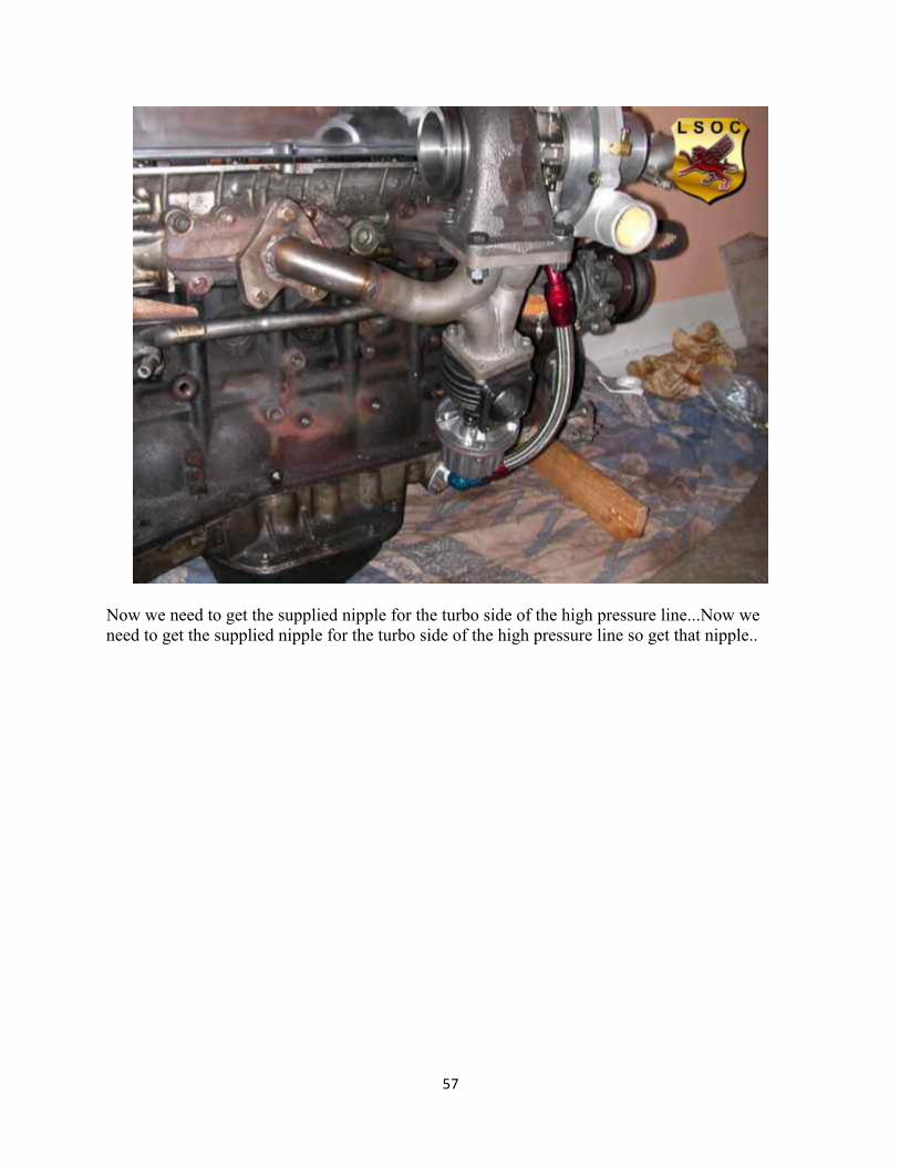
Now we need to get the supplied nipple for the turbo side of the high pressure line...Now we need to get the supplied nipple for the turbo side of the high pressure line so get that nipple..
58
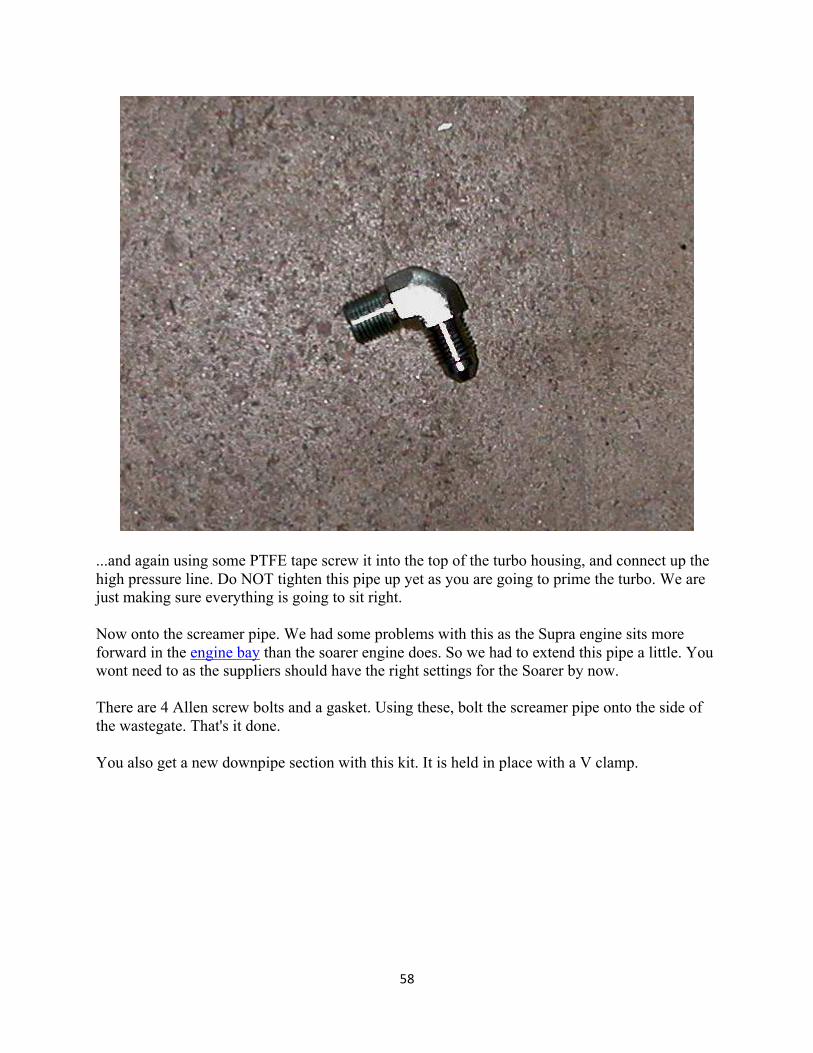
...and again using some PTFE tape screw it into the top of the turbo housing, and connect up the high pressure line. Do NOT tighten this pipe up yet as you are going to prime the turbo. We are just making sure everything is going to sit right. Now onto the screamer pipe. We had some problems with this as the Supra engine sits more forward in the engine bay than the soarer engine does. So we had to extend this pipe a little. You wont need to as the suppliers should have the right settings for the Soarer by now. There are 4 Allen screw bolts and a gasket. Using these, bolt the screamer pipe onto the side of the wastegate. That's it done. You also get a new downpipe section with this kit. It is held in place with a V clamp.
59
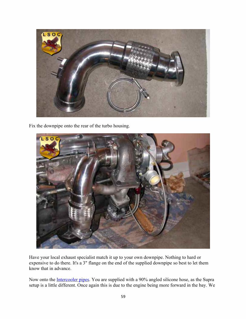
Fix the downpipe onto the rear of the turbo housing.
Have your local exhaust specialist match it up to your own downpipe. Nothing to hard or expensive to do there. It's a 3" flange on the end of the supplied downpipe so best to let them know that in advance. Now onto the Intercooler pipes. You are supplied with a 90% angled silicone hose, as the Supra setup is a little different. Once again this is due to the engine being more forward in the bay. We
60
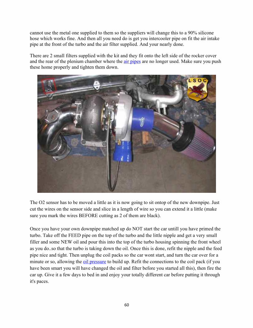
cannot use the metal one supplied to them so the suppliers will change this to a 90% silicone hose which works fine. And then all you need do is get you intercooler pipe on fit the air intake pipe at the front of the turbo and the air filter supplied. And your nearly done. There are 2 small filters supplied with the kit and they fit onto the left side of the rocker cover and the rear of the plenium chamber where the air pipes are no longer used. Make sure you push these home properly and tighten them down.
The O2 sensor has to be moved a little as it is now going to sit ontop of the new downpipe. Just cut the wires on the sensor side and slice in a length of wire so you can extend it a little (make sure you mark the wires BEFORE cutting as 2 of them are black). Once you have your own downpipe matched up do NOT start the car untill you have primed the turbo. Take off the FEED pipe on the top of the turbo and the little nipple and get a very small filler and some NEW oil and pour this into the top of the turbo housing spinning the front wheel as you do..so that the turbo is taking down the oil. Once this is done, refit the nipple and the feed pipe nice and tight. Then unplug the coil packs so the car wont start, and turn the car over for a minute or so, allowing the oil pressure to build up. Refit the connections to the coil pack (if you have been smart you will have changed the oil and filter before you started all this), then fire the car up. Give it a few days to bed in and enjoy your totally different car before putting it through it's paces.
61
62

63
64
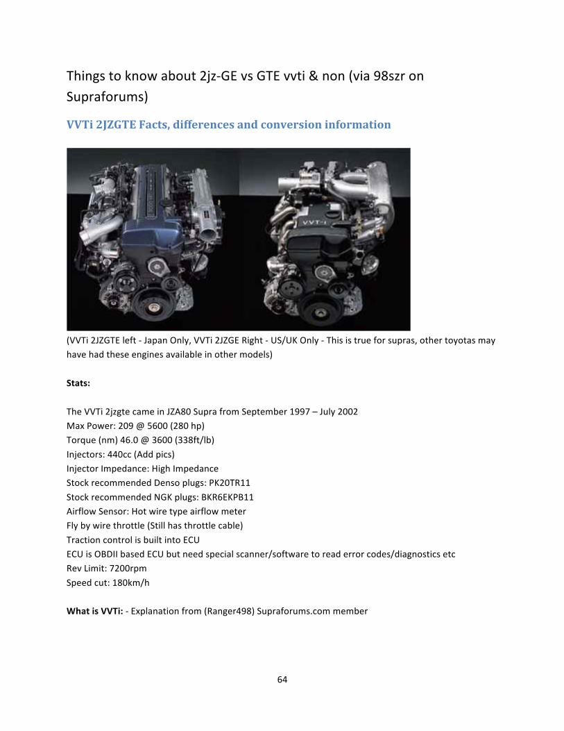
Things to know about 2jz-‐GE vs GTE vvti & non (via 98szr on Supraforums)
VVTi 2JZGTE Facts, differences and conversion information
(VVTi 2JZGTE left -‐ Japan Only, VVTi 2JZGE Right -‐ US/UK Only -‐ This is true for supras, other toyotas may have had these engines available in other models)
Stats:
The VVTi 2jzgte came in JZA80 Supra from September 1997 – July 2002 Max Power: 209 @ 5600 (280 hp) Torque (nm) 46.0 @ 3600 (338ft/lb)
Injectors: 440cc (Add pics) Injector Impedance: High Impedance Stock recommended Denso plugs: PK20TR11
Stock recommended NGK plugs: BKR6EKPB11 Airflow Sensor: Hot wire type airflow meter Fly by wire throttle (Still has throttle cable)
Traction control is built into ECU ECU is OBDII based ECU but need special scanner/software to read error codes/diagnostics etc Rev Limit: 7200rpm
Speed cut: 180km/h What is VVTi: -‐ Explanation from (Ranger498) Supraforums.com member
65
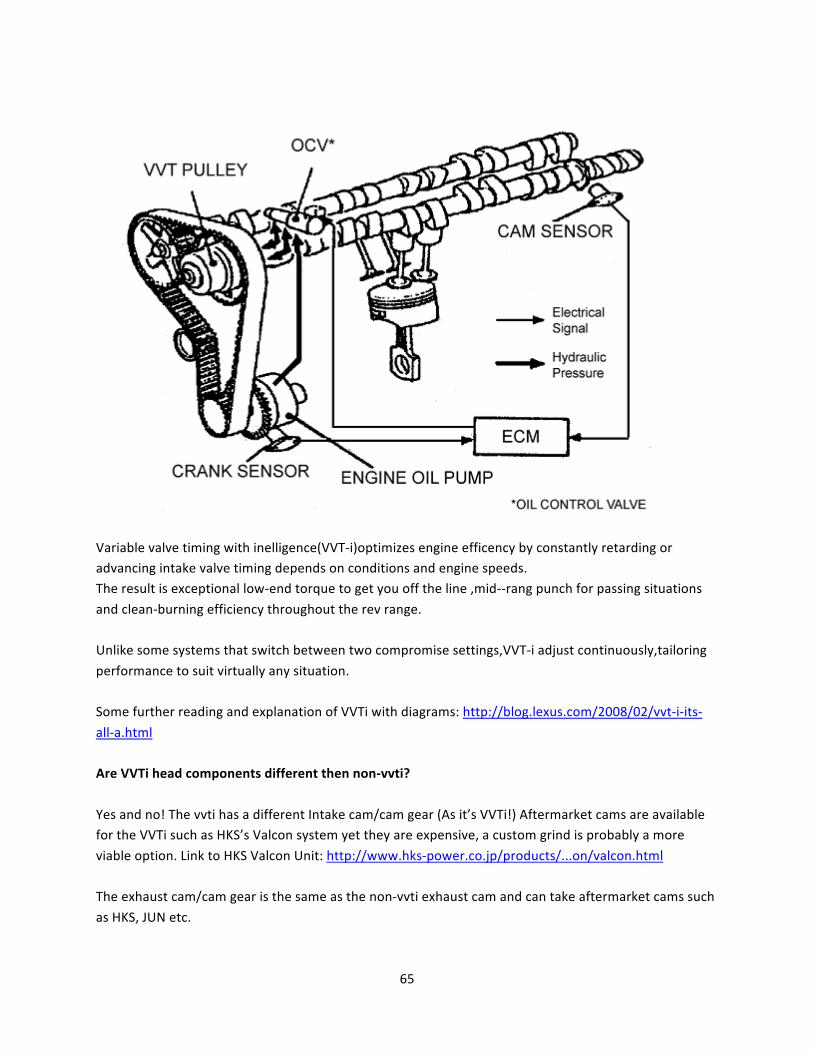
Variable valve timing with inelligence(VVT-‐i)optimizes engine efficency by constantly retarding or advancing intake valve timing depends on conditions and engine speeds. The result is exceptional low-‐end torque to get you off the line ,mid-‐-‐rang punch for passing situations
and clean-‐burning efficiency throughout the rev range. Unlike some systems that switch between two compromise settings,VVT-‐i adjust continuously,tailoring
performance to suit virtually any situation. Some further reading and explanation of VVTi with diagrams: http://blog.lexus.com/2008/02/vvt-‐i-‐its-‐
all-‐a.html Are VVTi head components different then non-‐vvti?
Yes and no! The vvti has a different Intake cam/cam gear (As it’s VVTi!) Aftermarket cams are available for the VVTi such as HKS’s Valcon system yet they are expensive, a custom grind is probably a more
viable option. Link to HKS Valcon Unit: http://www.hks-‐power.co.jp/products/...on/valcon.html The exhaust cam/cam gear is the same as the non-‐vvti exhaust cam and can take aftermarket cams such
as HKS, JUN etc.
66
The actual head components are the same (Well at least interchangeable with non vvti and aftermarket parts). These parts are listed below. The only difference I found in part numbers were the shims, not
sure on differences, may only be part updating and no physical change. Is the VVTi engine weaker?
No, some Toyota lovers will know that most of the later model vvti engines such as (1UZ, 3UZ etc) had weaker rods. The VVTi 2JZGTE rods are the exact same size as the non-‐vvti units. Also the crank is exactly
the same and so are the pistons and everything else in the bottom end. Below I have listed all the parts and they are exactly the same, they have been confirmed in the EPC (Toyota Electronic Parts Catalog) Pics are also shown below in the end of the post. The only 1 different part number I found was the crank
pulley (not the whole dampner/balancer, just the pulley, look like exactly the same thing, and they are!) What parts are the same as non-‐vvti? (Confirmed from EPC and personal experience and research)
Bottom end: Confirmed the same (EPC) , individual parts listed too. Shortblock: Yes
Balancer: Yes Pistons: Yes Piston Rings: Yes
Bearings (Rod and crankshaft): Yes Rods and rod bolts: YES! YES! YES!
Crank: Yes Head:
Exhaust Cam/Cam Gear: Yes Intake Cam/Cam Gear: No Springs: Yes
Retainers: Yes Buckets: Yes Seats: Yes
Intake and exhaust valves: Yes Valve guides: Yes Lifters: Yes
Locks: Yes Seats: Yes Shims: Same but different part numbers
Other: Timing Belt: Yes
Top radiator pipe: No (Different size) Throttle cable: No (Different size)
67
Intake manifold: Can be swapped but has different vacuum piping Exhaust Manifold: Yes
Electrics/ECU: ECU: No
TRAC: No (Built into the ECU) VVTi – ETCS Fuse 15amp Non vvti -‐ TRAC fuse with 7.5amp
Aristo Engine differences: The VVTi 2jzgte engine also came in the Aristo (1998-‐2002), as I’ve done a conversion using this engine I
can provide some information on the differences, also please don’t PM me all the information is here and in my project thread found here: http://www.supraforums.com.au/forum/...ad.php?t=25065
If you are swapping this engine into a supra you will need to do the following: -‐ Aristo power steering pump has a solenoid valve which the supra doesn't, mainly this effects the power steering lines as the bolt configuration is different, you will need a supra one
-‐The water pump is the same on the VVTi and is not hydro – it will not need to be changed -‐The aristo has a front mounted sump, you will need to change to a supra mid mounted sump layout. -‐Engine loom will need to be modified or swapped for a supra unit
-‐Engine Mounts and brackets will need to be swapped
-‐Brake booster bung (Goes to top of intake manifold)
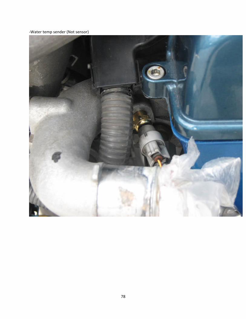
-‐o2 sensor loom plug will need to be swapped -‐Water temp sender (Not sensor) will need to be purchased and installed -‐Oil level sensor plug may need to be purchased
-‐Heater hoses from engine will need to purchased as the aristo ones are different -‐Oil dip stick bracket is different -‐Oil return lines from turbos are different
-‐Fuse box will need custom wiring, some differences: ETSC (TRAC Control) fuse is 15amp, I setup the wiring for FAN (Don’t have them though), EFI1 and EF2 relays and fuses were setup as NA only uses one EFI relay, TEL Fuse Wiring,
Aftermarket ECU: Things to keep in mind if keeping vvti functionality:
FBW (Fly by wire) Controlling VVTi (Oil control/pressure sensor) Finding a tuner!
Choices are probably limited to: Motec M600/M800 -‐ VVTi and FBW support -‐ http://www.motec.com.au/home
Autronic SM4-‐ VVTi support -‐ http://www.autronic.com.au/ HKS F-‐con V Pro -‐ VVTi and FBW support but only 2 HKS Pro dealers in Australia that can tune it -‐
68
http://www.hks-‐power.co.jp/products/.../fcon/top.html Haltech E11V2 -‐ VVTi support -‐ http://www.haltech.com/e11v2.htm
AEM -‐ VVTi support -‐ http://www.aempower.com/ViewCategory.aspx?CategoryID=62 ViPEC V44 and V88 -‐ VVTi and FBW support (V88 only supports FBW) http://www.vi-‐pec.com
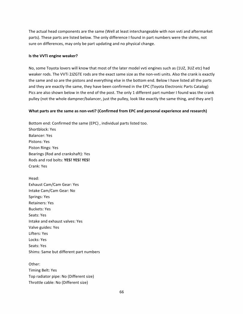
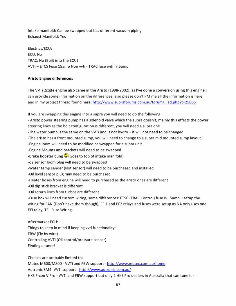
Original Engine:
69
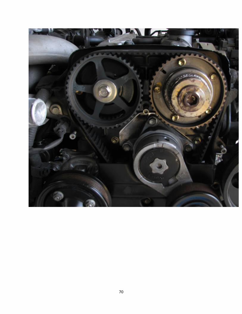
70
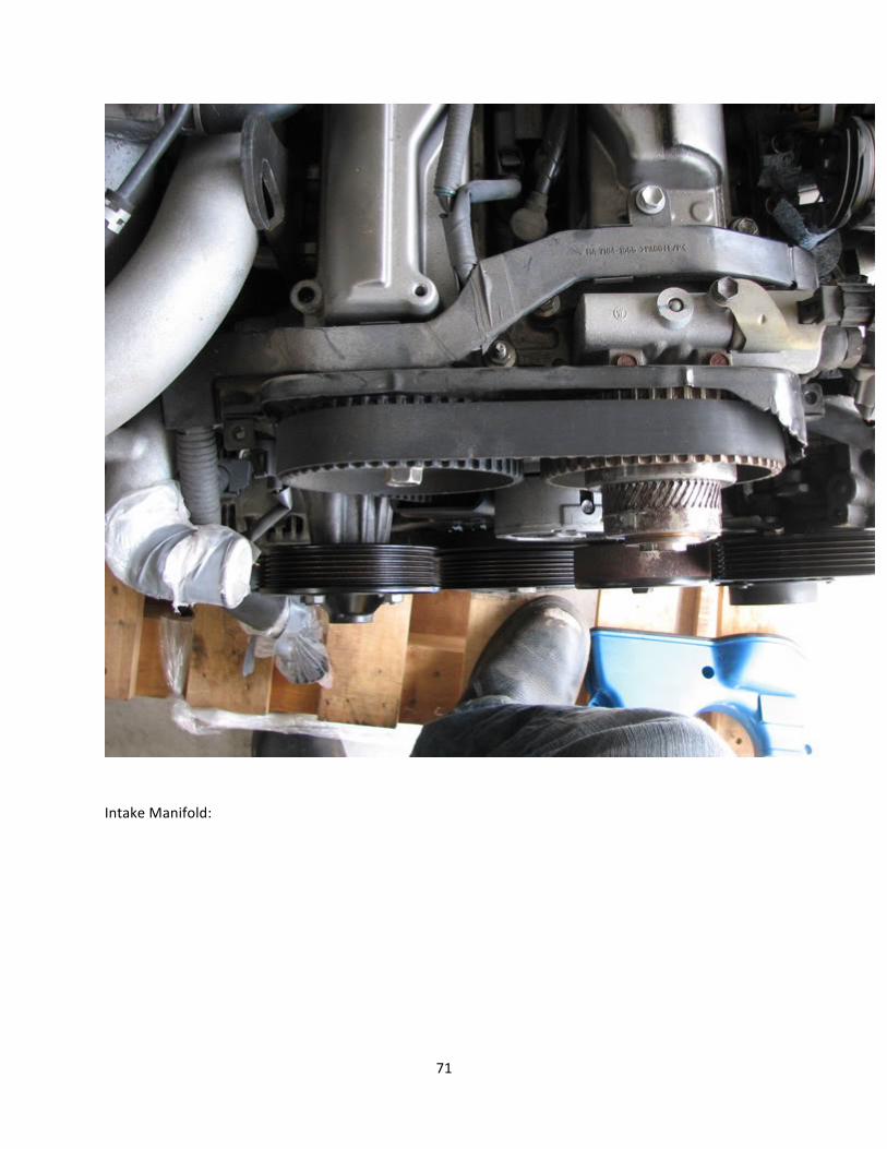
71
Intake Manifold:
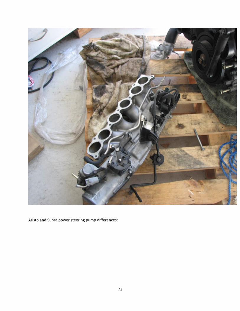
72
Aristo and Supra power steering pump differences:
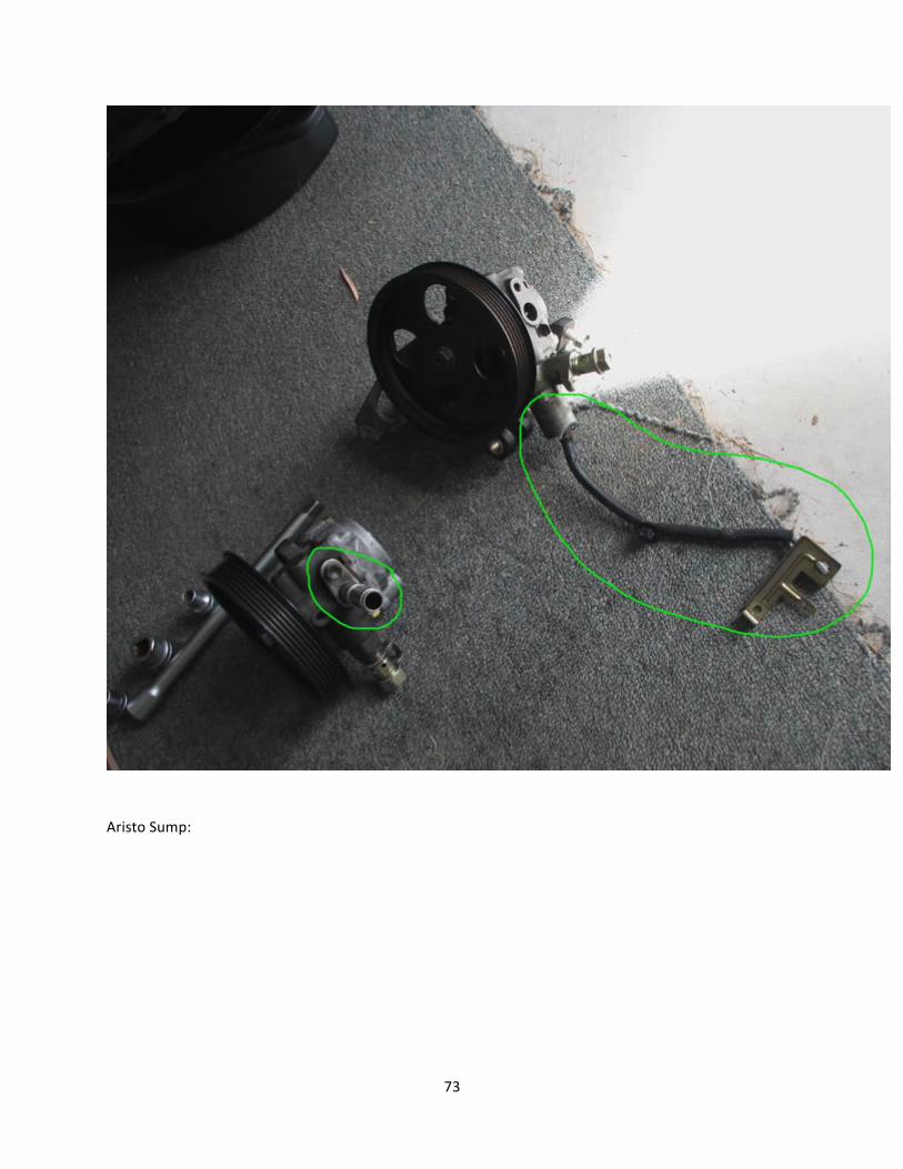
73
Aristo Sump:
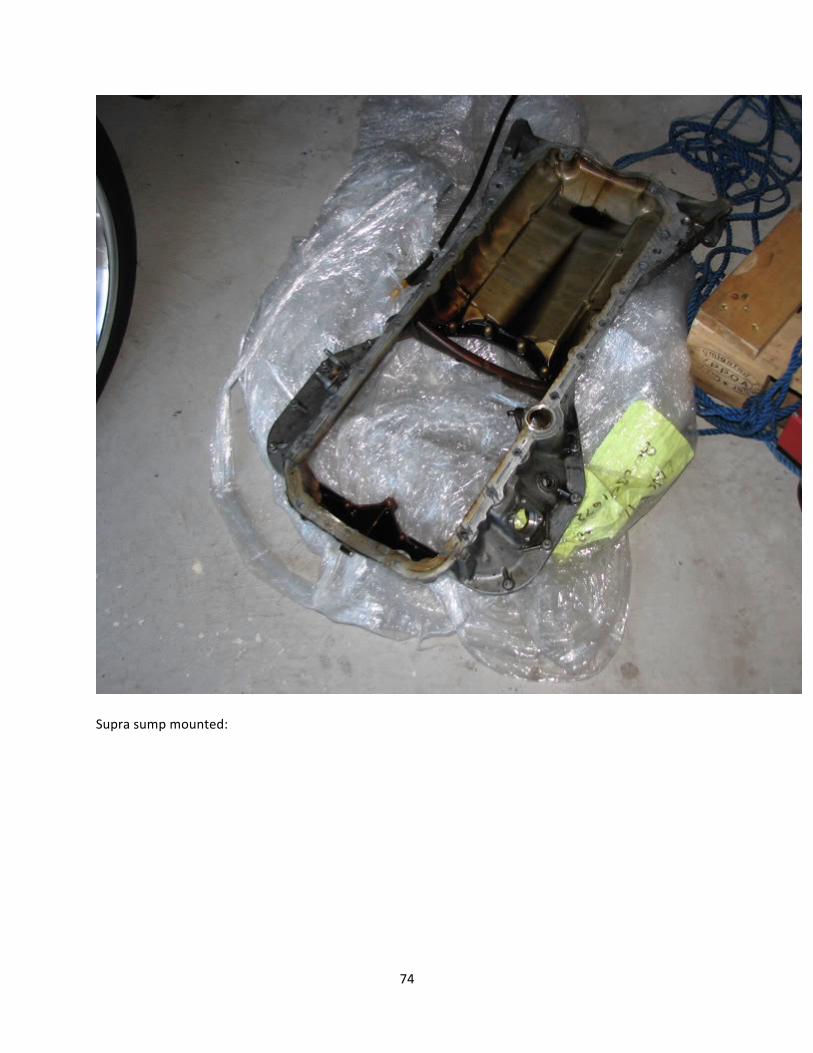
74
Supra sump mounted:
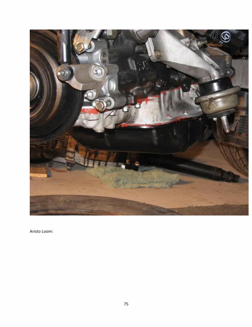
75
Aristo Loom:
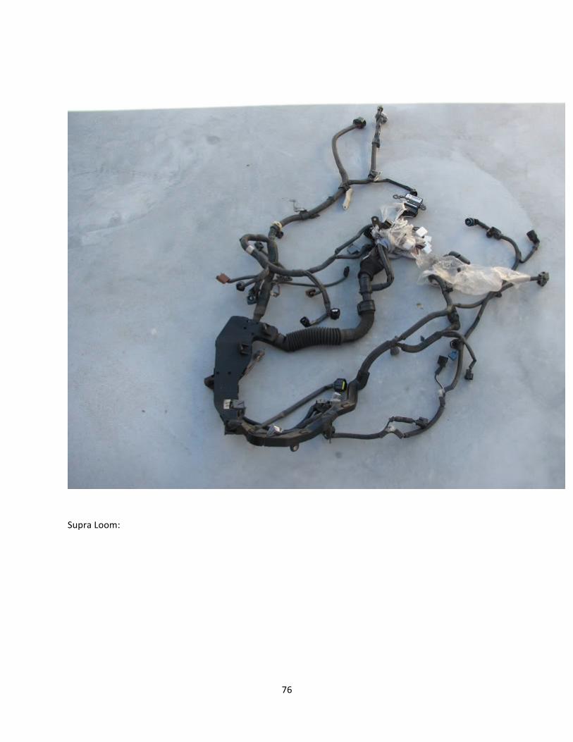
76
Supra Loom:
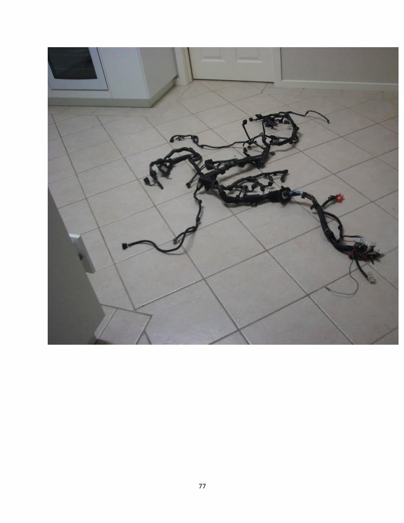
77
78
-‐Water temp sender (Not sensor)
79
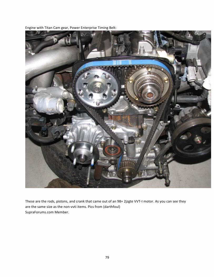
Engine with Titan Cam gear, Power Enterprise Timing Belt:
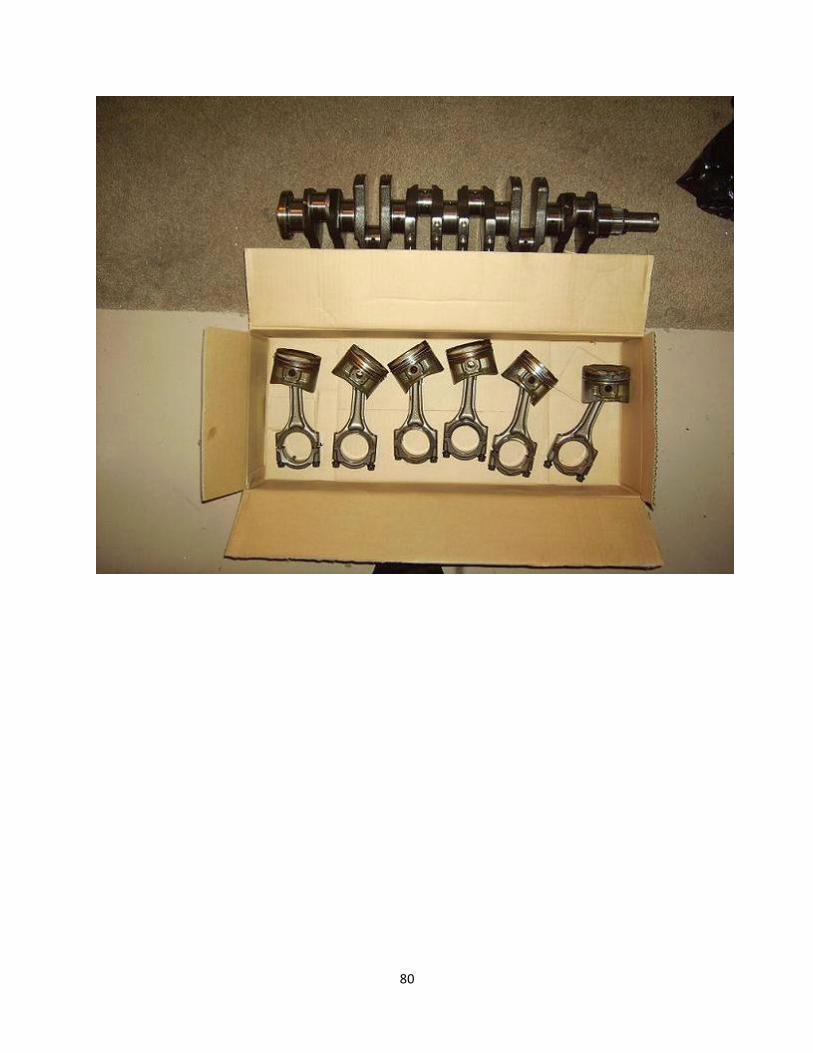
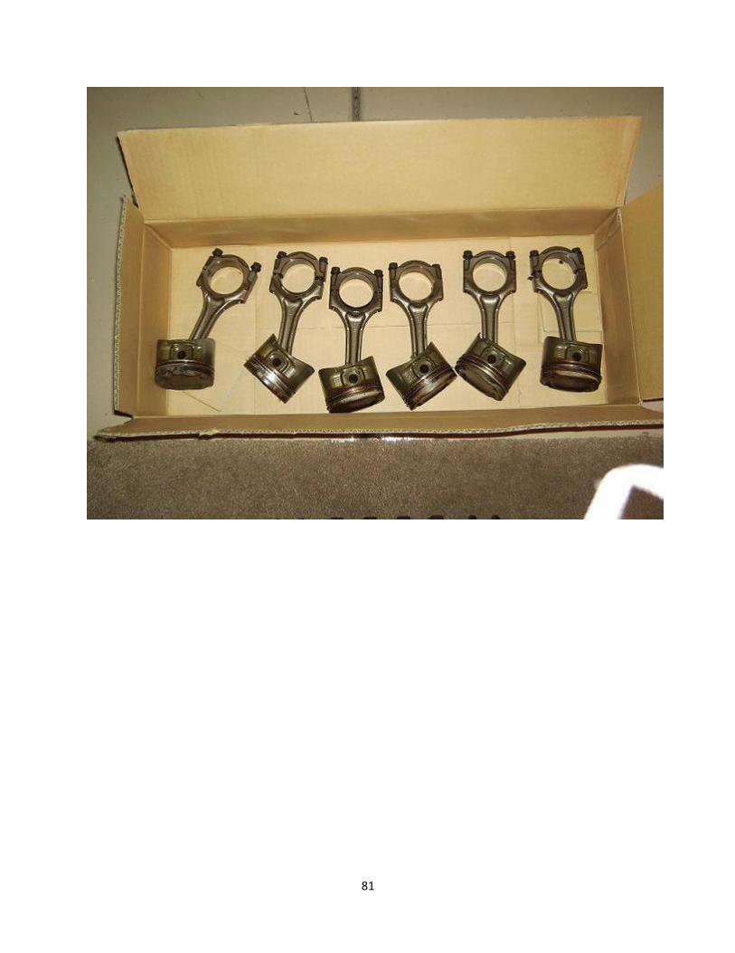
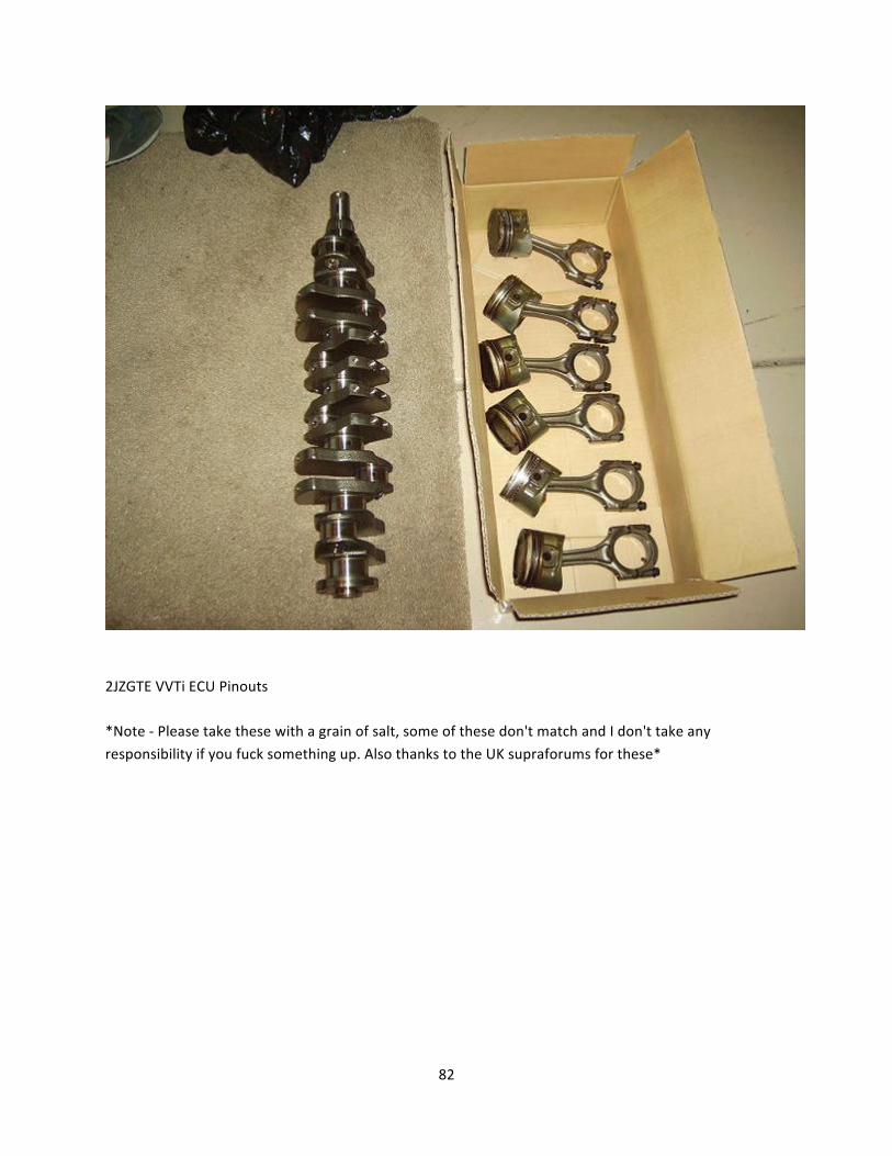
These are the rods, pistons, and crank that came out of an 98+ 2jzgte VVT-‐I motor. As you can see they are the same size as the non-‐vvti items. Pics from (darthfoul)
SupraForums.com Member.
80
81
82
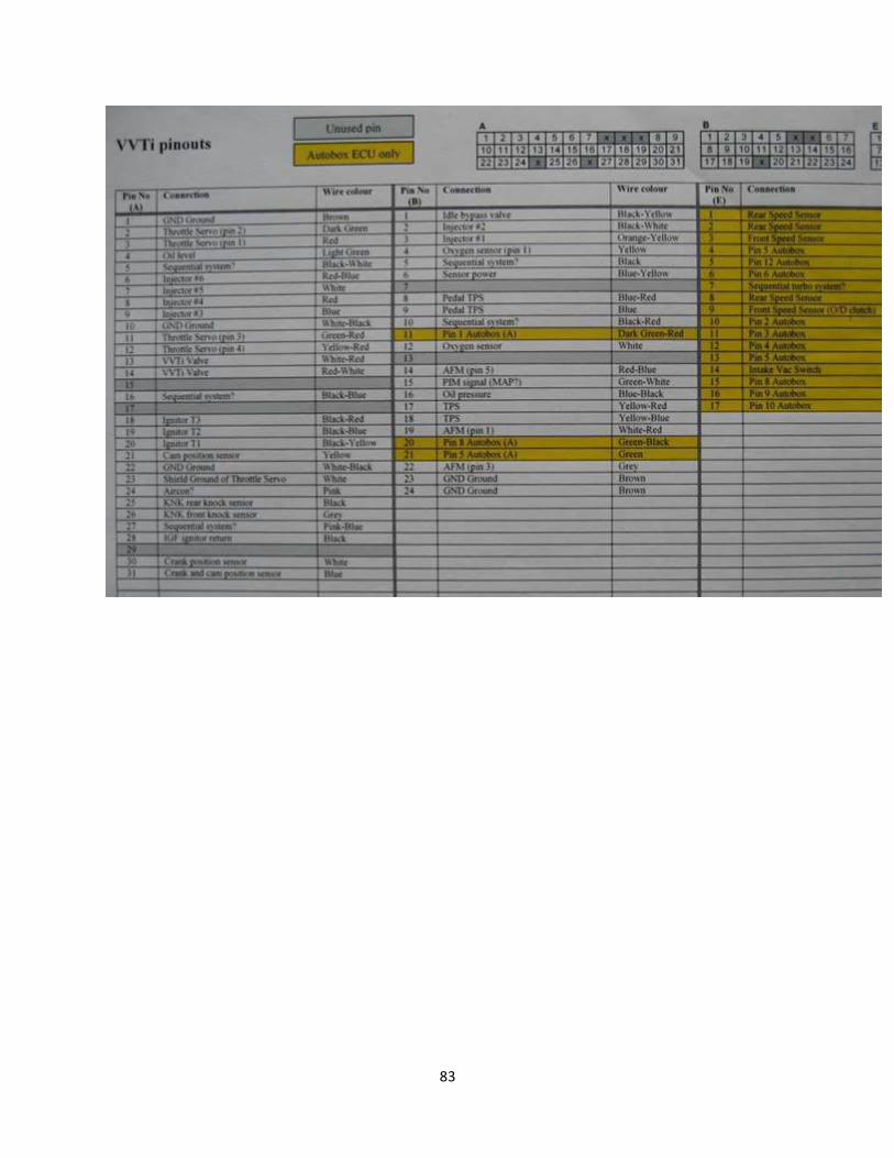
2JZGTE VVTi ECU Pinouts *Note -‐ Please take these with a grain of salt, some of these don't match and I don't take any
responsibility if you fuck something up. Also thanks to the UK supraforums for these*
83

84
85
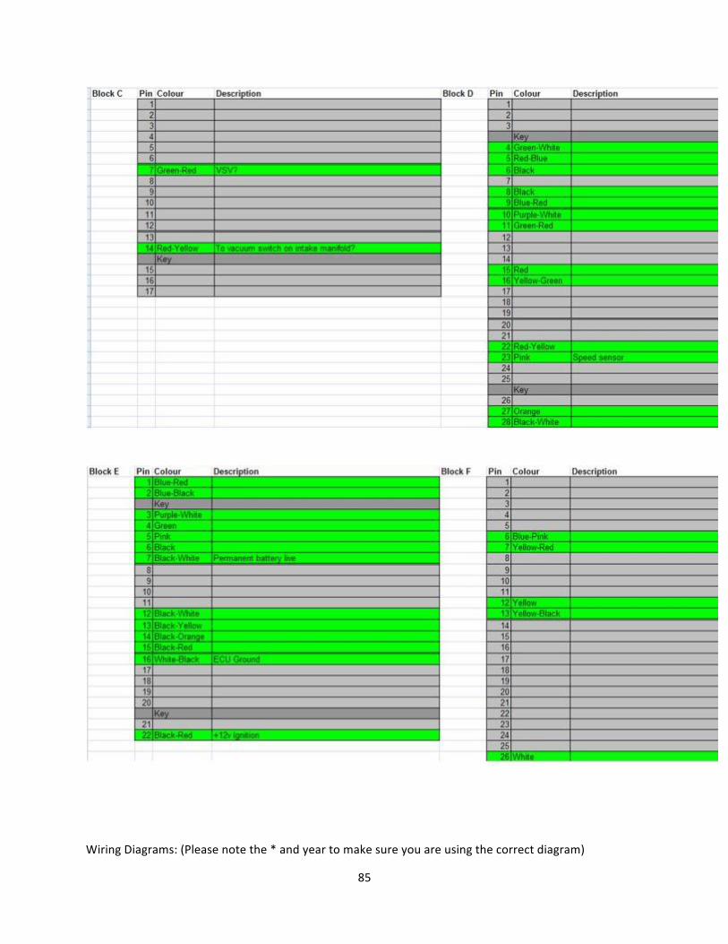
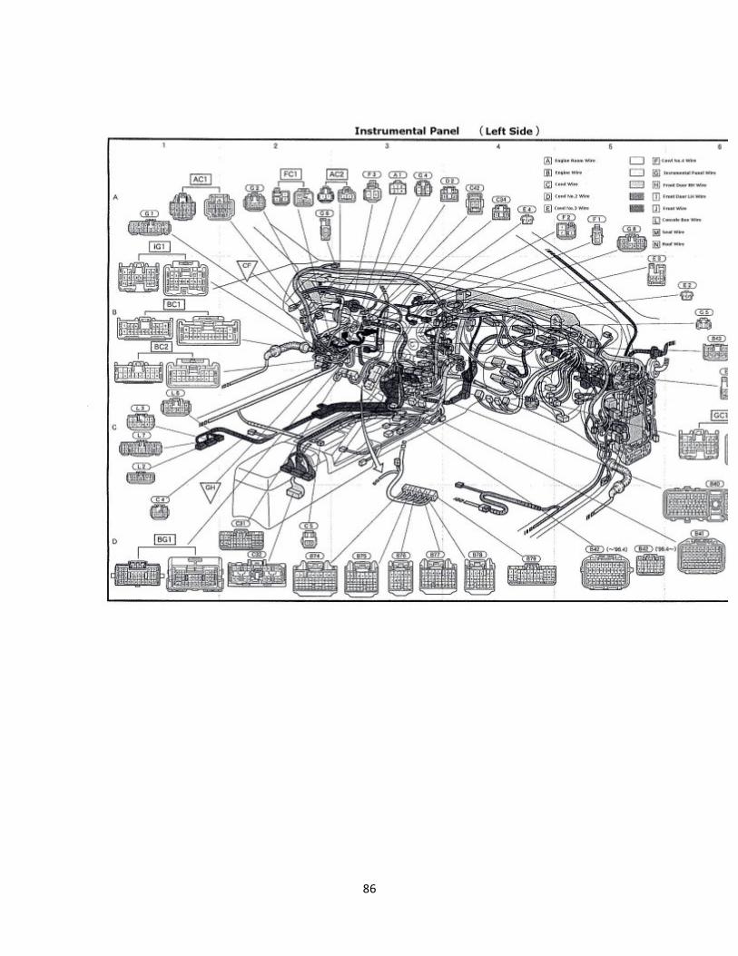
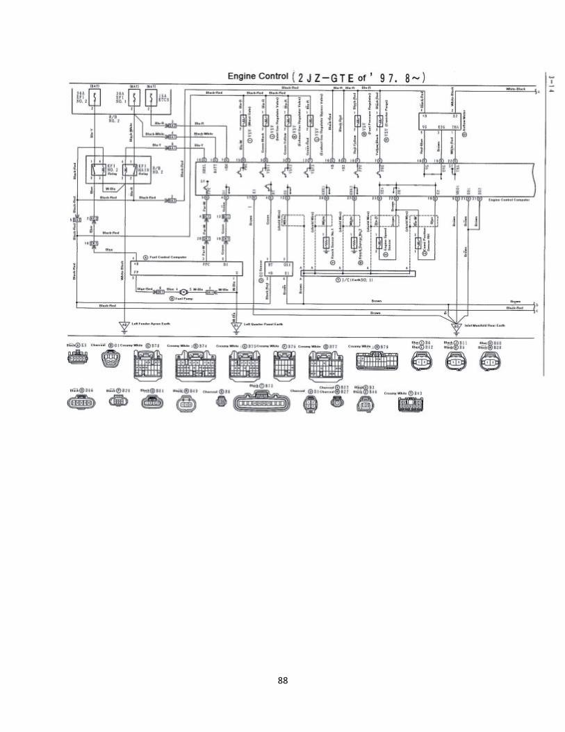
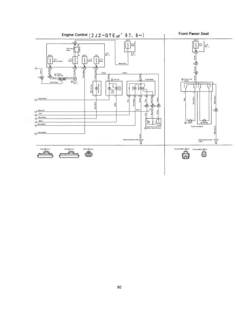
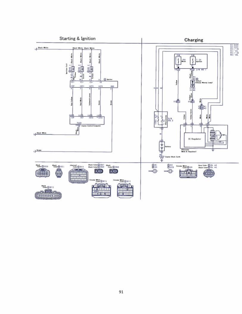
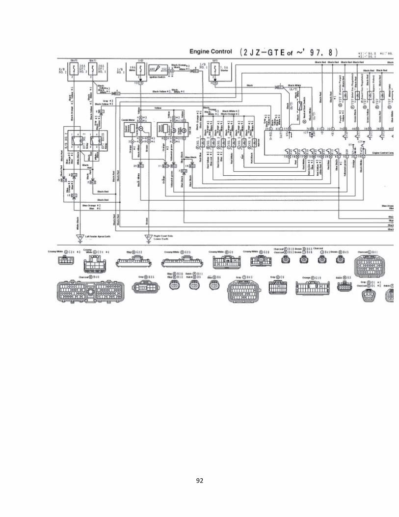
Wiring Diagrams: (Please note the * and year to make sure you are using the correct diagram)
86

87
88

89
90
91
92
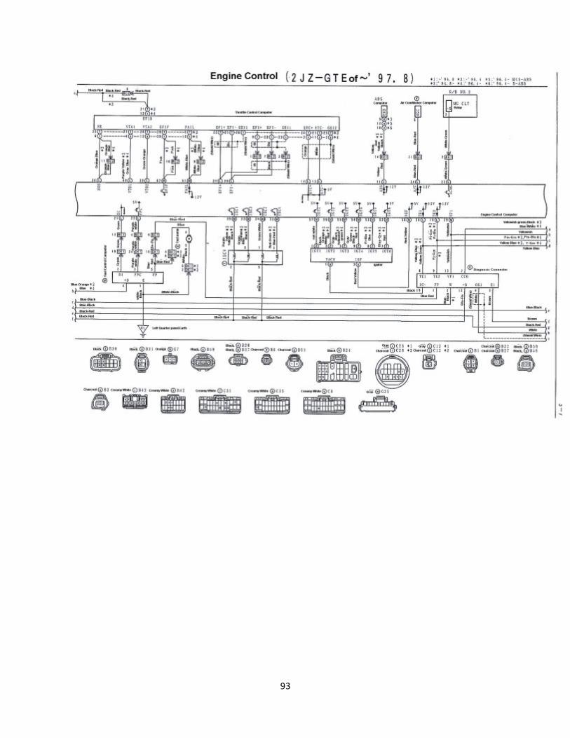
93

94
95
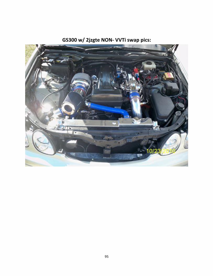
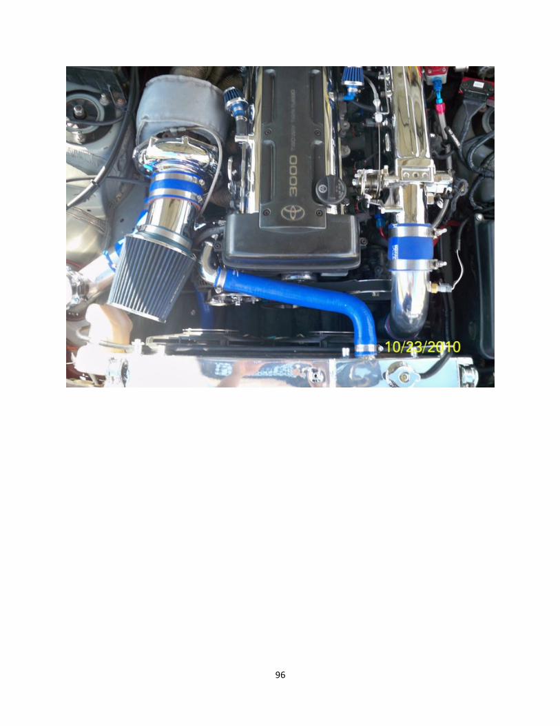
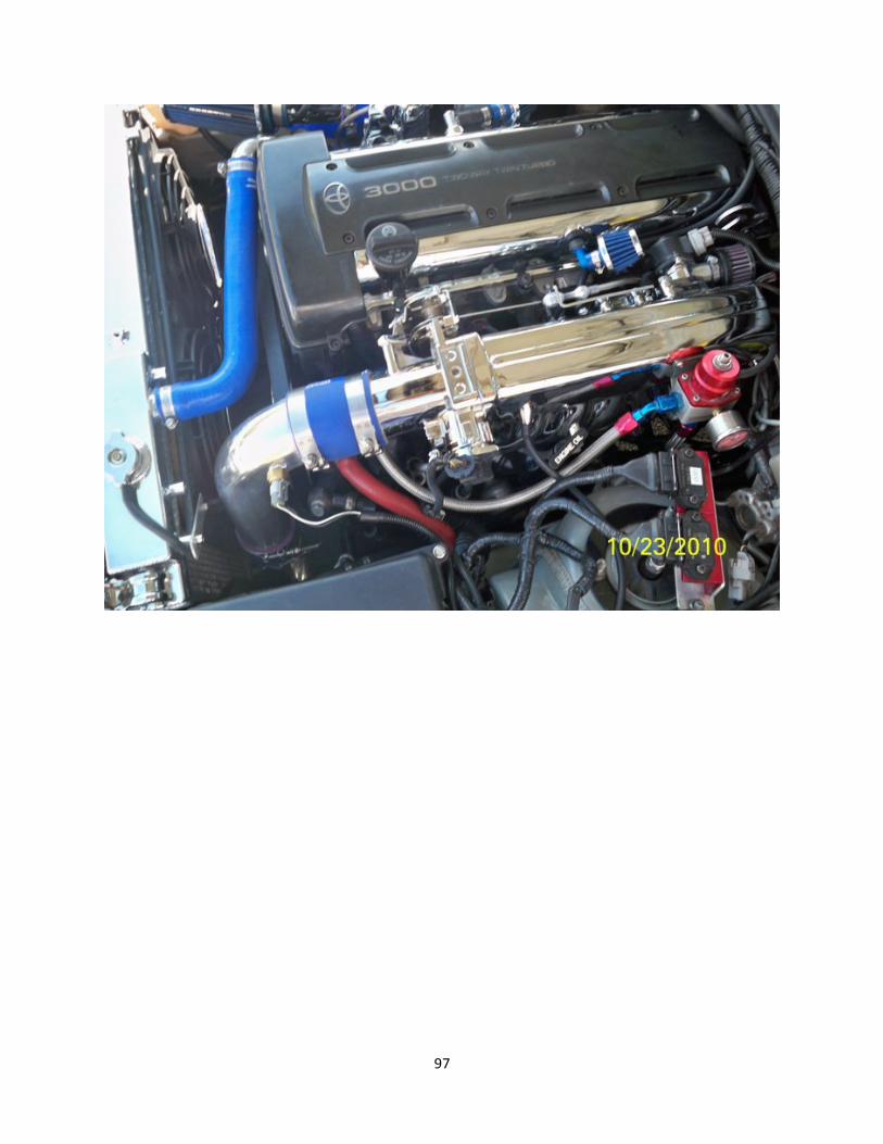
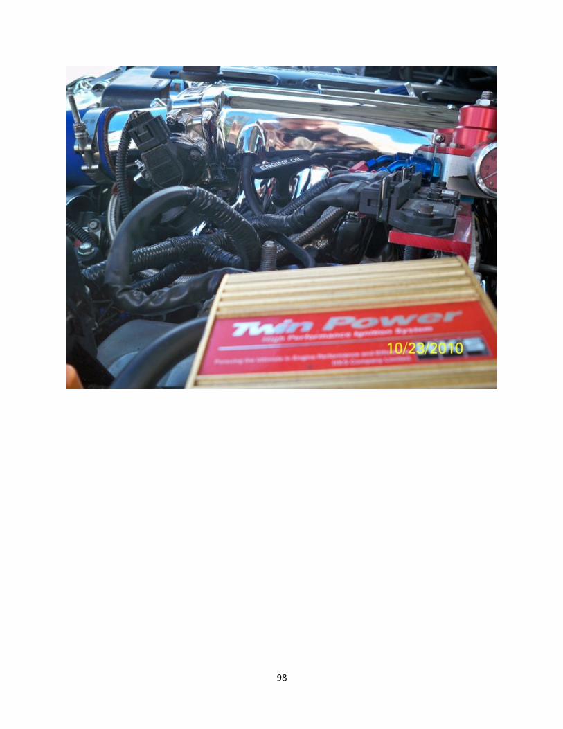
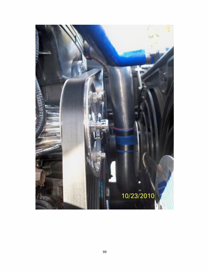
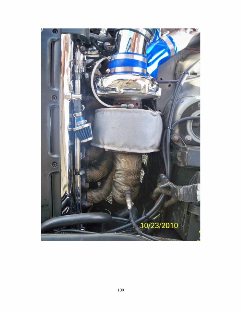
GS300 w/ 2jzgte NON-‐ VVTi swap pics:
96
97
98
99
100