ip90002.pdf - Federal Highway Administration
349
-
Upload
khangminh22 -
Category
Documents
-
view
0 -
download
0
Transcript of ip90002.pdf - Federal Highway Administration


Foreword
The Traffic Detector Handbook is a product of the Federal Hi hwayA&inis trat ion technology transfer progrm. It is intended foruse by traffic engineers and technicians having responsibility for.the design, installation and maintenance of traffic detectors.
Judicious application of the concepts and procedures set forth inthe Handbook should result in improved installations of trafficdetectors and a long-term savings of public funds.
Other resources to assist with selection and installation andmaintenance of traffic and vehicle detectors are underdevelopment. They include a Traffic Detector Field Manual and avideotape training course. Both will be tied to the Handbook andwill focus on practical considerations in installing andmaintaining detectors .
Sufficient copies of this Handbook are being distributed toprovide a minima of one copy to each PHWAre$ional office,division office, and State highway agency. Direct distribution isbeing made to the division offices.
FQ%w[k
Director, Office of Implementation
Not ice
This docment is disseminated under the sponsorship of theDepartm&nt of Transportation in the interest of informationexchange. This Handbook does not constitute a standard,specification or regulation.
The United States Goverment does, not endorse products ormanufacturers. Trade and manufacturers’ n-es appear herein onlybecause they are considered essential to the objective of theHandbook.

Technical Report Documentation Page
1. Report No. 2, G.v.,. me., Accession No. 3. Recipients Catalog No.
~A-IP-90-0025. Ti,le ond SVb,;,le 5. Rep.,, D.,.
July 1990HFIC DETECTORWBOOK 6. Performing Orgonizn,io” Code
8. Performing 0.9..; ..?;.. Report No.7. A“+ho,!s)
James H. Ken, Iris J. Rllerton, filton K. ~lls9. Performing Orgoniz.tion Name and Address 10. w.rk u.;+NO. (T RAIS)
JHK & Associates 3B9aO0832000 Powell Street, Suite 1090 11. Co”,ra<, o, G,.., No.
Meryville, CA 94608 DTFH61-88-C-0002013. Type of Rep.,, and Period Covered
12. Spo”,oring Agency Name ond Address
U.S. Department of Transportation Technical Wdbook
Federal Highway Administration my 1988 - Jdy Iggo
Office of Research and Development 14. SpO.,O,i”g Agency Code
15. Supplementary Notes
WA Contracting Officer’s Technical Representative: Juan Mrales (~T-20 )Roger Man (~T-20)
NA Contract Administrator: Roger ~rtin (HCP-42 )16. Ab,troct
~is handbook is a revised, updated version of the Federal Highway Administration’:(WA) Traffic Detector findbook, originally published as Implementation PackagemA-IP-85-l . This upgraded version of the Handbook supersedes and replaces theprevious edition. It has been restructured, corrected, and revised to u@atediscussions of concepts and equipment to reflect the current state of the art,particularly as it relates to the microprocessor revolution, advances in controltechnology, and real-world application e~rience.
me overall objective of this Handbook is to provide a single resource and basicreference to aid the practicing engineer and technician in planning, designing,installing, and maintaining detectors.
It provides a compendium of existing detectorstanding of all aspects of detector systems.with emphasis on proper design, applications,techniques.
technology to facilitate the mder-Best current practices are describedand installation processes and
17, Key Wordsktectors, Inductive hops, ~gneto-
10. Di stri b.tion S+o+ementThis docment is available to the public
meters, Mgnetic Mtectors, Traffic through the National Technical Inform-Signal Control, Traffic Surveillance at ion Service, Springfield, VA 22161& Control, Veticle Mtection, SystemSensors.
19. Security Class; f, (of this repori) I m. Security Clossif. (of ,his p.ge) I 21. No. of Pmges I 22. P,: . .
Unclassified Unclassified 354
Form DOT F 1700.7 (8-72) Reprod”ctio. of completed page o. fho,ized

METRIC CONVERSION FACTORS
Approximate Conversions to Metric Measures Approximate Conversions from Metric Measures
Symbol When you knowMultiply
byTO Find Symbl Symbol When you know Multiply
byTO find Symbol
~ LENGTH
in inches 25.4 millimeters mm mm millimeters 0.04 inches inin inches ‘2,54 centimeters cm cmft
cent imeters 0.4 inches infeet 0,3 meters m m
vdmeters 3.3 feet ft
vards 0,9 meters meters 1.1 Vards;m
vdmi miles 1,6 kilometers ~m blometers 0.6 miles mi
~ B
in2square inches 6.5 square centimeters
~mz ~m2square centimeters 0,16 square inches
i“2
ff2square feet 0.09 square meters
~2 ~2square meters 10.8 square feet
ft2
yd2 square yards 0.8 square meters m2 m2 square meters 1.2 square yards ydz
miz square miles 2.6 square Klometers kmz km2 ~q”are ~lometer~ 0.4 square miles mi2
acres 0.4 hectares(10,000m2) ha ha hectares(10,000 m2) 2.5 acres
MASS (weiaht) MASS (weiaht)
02 ounces I 26.4 I grams I 9 9 19 rams I 0.0351 ounces Ilb pounds
020.46 I kilograms kg kg I kilograms 2.2 pounds lb
shoti tons (2OOOlb) 0.9 mettic tons metric tons 1.1 shon tons
VOLUME VOLUME
fl Oz fluid ounces 29.6 milliliters ml mlpt
milhliters 0.03 fluid ounces fl 02pints 0.47 liters I I liters
qt2,1 pints pt
quafls 0.95 liters I I liters 1.06 quarts qtgal gallons 3.6 liters I I liters 0.26 gallonsfts
gal
cubic feet 0.03 cubic meters~3 M3
cubic meters 35.3 cubic feet fts
yd3 cubic yards 0.76 cubic meters m3 m3 cubic meters 1.3 cubic yards yd3
TEMPERATURE (exact) TEMPE RATURE (exact)
5/9 (after. . F Fahrenheit temperature subtract Celsius temperature “c
. . c Celsius temperature 9/5 (then Fahrenheit ., Fing 32”) add 32”) temperature
. 1 incheq”ats2,54 ~“timeters exacfly, Forotherexactmn.ersio”$ and moredetailedtables, .. Exactmnversio”.see NBS Msc. P“bl.286, UnitsofweightsandMeasures. ihl
) ,) ‘)

-
T=LE OF CONTENTS
I. ~TRODUCTION
SCOPE ~ OB~CTmS OF T~ -BOOKEVOL~ION OF DETECTOR TECHNOLOGYINTRODUCTION TO MODERN DETECTOHSDEFmnON OF TEWS
ORGM~TION OF -BOOK
2. DETECTOR TEC~OLOGY
INDUCT~ LOOP DETECTORSBMIC ~INCIP~S * WEORYOFOF~RATIONS
Loop System WsistanceLoop hductanceFe-magnetic Effect
LWP CWMCTERISTICSLoop CapacitanceLoop Quality Factor, QLoop Lead-In WireLoop Lead-In Cable
D~nMINAT1ONOFINDUCT~CELoop System bductance CalculationsRequired Number of T-sLoop SensitivityBicycle DetectionDetiction with Rectangular or Square LoopsMutual hductance
NO=~D LOOPhUCTMCE (S~NSITMm)Effect of Winforcing SteelLoop System Sensitivity
Sensitivity of%0 Series InductorsSensitivity of %0 Parallel InductOmSingle Loop Exampletio Loops in Seties Example%0 Loops Connected in Parallel Example
Resonant CircuitDHEmR ELECTRONICUNIT
halog Phase Shift Detectir UnitOveMew of Digital Detector Units
Digital Frequency Shifi Detector UnitDigital Ratioed Frequemy Shifi Detector Unit
,-. Digital Period Shift Detector UnitDigital Ratioed Period Shifl Detector UnitComparison of Digital Detectom
1
11
256
7
778899
10111314151516161617171820202121212324242526262828293131
.,.m

Traffic Detector Handbook
Multichannel Digital Mo&lsRecent Advances in Digital Detectors
Open Loop Test FeatureAutomatic Reset FeatureRemote Reset FeatureZtiepen&nt Loop Fail Ou@ut
~~ %NUDSDe@ctor Unit Confi@rationsModes of OpemtionOutput TypesCrosstalkTiming Features
WE 170 *EclF1cAT1ONModel 222 / 224 Loop Detectors
SEmCTIONFACTORSfining RangeResponse TimeWcovew from Sustained OccupancyLoss of Detection during Satwated NowSensitivity with Pavement OverlayPulse-Mode ResetOperation with Grounded or Open LoopsLightning Damage / Electtiml Intefiemnce
WGNETOMETER DE~CTORSMODEL228 WGN~METEB DmECTORWOBY OF OPEmTIONS
PROBE CWWCTERISTICSOWRWW OFWGNmOMHER DHEmR SYSTEMSENSITMTYAND~BESHOLDINGEmcTROmcS N CONTROL
mG~TIC DETECTORSMODEL232 / 234 WONETICDHEClIORSWOBY OFOPEWTIONSPBOBEC=CTERISTICS
ELECTRONCSUNIT
3. DETECTOR APPLICATIONS
OWRWW OF TRAFFIC CONTROL CONCEPmCONTROLCONCEmSFORC1m STREmSCONTROLCONCEPTSFORFREEWAYS
FUNCTIONAL DESCRIPTION OF DEmCTORS
LOCAL INTERSECTION CONTROLCONTROLMODESDHECTIONOFPRIORITYVEHICLES
Light Emitter&ceiverVehicle Identification Conceptfiasit Vehicle Signature - Loop DetectorWdio ~ansmitter~eceiver
SIGNm SYSTEM CO~ROLARTERW STBEm SYSTEMS
3Z323232323333333434343435363636363737373737
::3939404141
::43434343
45
4545
:;47474s484949
::51
.—
iv

Table of Contents
P
N-ORK CONTROLFREEWAY SURmILLANCE AND CONTROL
E=CE ~P CONTROL-p CIOsme=mp Meteringktegrated ~mp Control
~NE CONTROLOmER APPLICATIONS
SPmD MONITORINGToo FASTWmN FmHINGP~~E TO STOP
Wmc COUmINGMD VEHICmCWS1F1CATIONCmmts by Loop DetectorsCounts Using Long LoopsDtiectiond Detection
NPOWY LOOPSMat-we LoopsOpsn ~op Confi@mtiOnVehicle Classification Devices
PEDESTKMDmECTOBS
4. DETECTOR DESIGN
SEmCTION CRITERIASELKHIONBASEDONOPEMTIONSMORYSEMCTIONBASEDONAPPLICAmONSELEHIONBASEDONEME OFINSTUTIONSELEHIONBW~D ONE~E OF mNTENANCE
DESIGN CONSIDERATIONStilNG P-mERS
Minimum Green Inte~alPassage ~me InternalMsximum Green IntenalVolume Density Mode
bw SPEEDAPPROACHEShcting Memo~ with Point DetectionNonlocking Memory with Presence Dete{
~GH-SPEEDAPPBOACHESRural High-Speed Raadways
WSVIN-RED SPEEDCowrRoLLooP DETECTOR DESIGN AlternateS
SW km DmECT1ONLARGEARM DmECTION
Lang LoopsSequential Shoti LoopsWide Loops
LEm-TmN LANEDET~CTtONWOUGH ~ DHECTION
Single Point Detectionbop Occupancy DetectionHigh Speed Point Detection
:tion
::
52525254
57585859606061616161616363
65
65656565
::666667676869696970717273737474777s7980808081
v

Traffic Detector Handbook
DSTECTIONFORDIWW ZONESDefinition of Dilemma Zone ProblemMdtiple Point Detection
Green Extemion SystemExtended Call Detector SystemMultiple Point Detector Methods
The Beirele MethodThe Winston-Salem MettiThe SSITE Method
Typical Desi@ OptionsFUNCTIONAL APPLICATIONS
DmEmlON OF SMti VEHICLESMdtiple titerconnected Small LoopsQnadrnpole Loop ConfiwationChemon Loop Confi@rationbng Loop with Power HeadBicycle Detectam
D-CTION OFLONG,HIGHBEDVEHICLESQ~UE D=CTIOND~E~R DESIGNFOBTRWFICCONTROLSYS=S
818185858586868686
:;89899091929293M95
LooP
Accmacy Goals 95Link Selection for CIC 95Lane Selection 96Longitudinal Placement 96Summm of System Detector LocationDETECTOR E~CTROmC UNITS :;
MAG~TOME~R CONFIGURATIONSSITESELECTIONSENSITm~PROBEPMC~E~PROBEDE-SUGGESTEDCONEtGUWTIONSWmE SIm N C=LE SELECTION
MG~TIC DETECTOR CONFIGUmTIONWGNETICDmECTORPROBEPMCEMENT
Distance tiom the Stop LineLateral Placement of Robe
SENSITMTY
5. INSTfiLATION
fiPICAL P~-INSTALLATION ACTMTmSSCALEDRAWNGOFLOCATIONFIELDVISITS-PowaE EST~ATESEQUIP~NTREQUI~MENTSWTERIW REQUIHEMENrS
LooP DE~CTOR INSTALLATIONWSTALLAmON~cwQuEsD~EcTOR FMLURES
Causes of Detector Failure
989898
100100100100101102102102103
105
10510510610610610610710s —.110110
vi

Table .ofContents
,-
frequency of FailuresFail~e Mechanisms
hP hYOUT mD SAWCmsCorner MatmentSaw Cutting Operations
Overview of Saw Cutting EquipmentDiamoti Blade DesignSaw Blade Trouble ShootingSaw HorsepowerWet versus DV CuttingSaw Cut DepthFinishing the Saw Cut
hSTUNG LGOPWIREWire Type
Ducted WirePrewound LoopsPreformed LoopsMetal Sheathed Loop Cable
Wtie InsertionCROSSINGPAWENT JOINTSWHNG T~ LOOFWIRELH-WCROSSINGCURBSWSTWTION OFPum Box m CONDmTtiSTING THE LOOPSWNG T~ SAWCm
Types of SeakntsTechniques for Sealant Application
SPHCINGTREWIREConnecting the WiresEnvtionmentally Sealing the Splice
Lw-W CABm INSTmWTIONFIN& ~STS MD RECORDKEEPINGGEmw tiSTfiUTWN GWIDEHNES
DETECTOR INSTALLATION hTEmAmSSm tiPsROUNDLOOPS
INSTALLATION OF tiGNETO~TER DETECTORSWSTUTION OFSENSINGPROBESPUCXNGTm CABmsfiSTINGTm SYSTEMSWNG TREHems w Cms
INSTALLATION OF WG~TIC DE~CTORSWSTUTWN PROCEDURETRENCmNGCONmCTINGTHESYST~~STING Tm SYSFEM
6. DETECTOR ~TEN~CEm NAT- OF T~ PROBNM
FMLURES IN LooP DETECTOR SYSTEMS
110.111111111112
112113113114114115115115115
116116117118118119121121123124125125127128128129130131133
135135137
138138139140140
140140141141142
143
143144
tii

Traffic Detector Handbook
FMLnE MECMISMSOmitted PhaseStuck Si@alPhase Extending to MaximumIntemittint ProblemsCrosstalkSplashover
CAUSESOFLOOPSYST~ FWL~EFACTORShFECTING NEEDEDWNTENANCE
TRouRm SHOOTING PROCEDU~S FOR LooP DETECTORSSAWCUT ~~ENWCERHRANG-NT OFLOOPCONNECTIONSEWINATING CROSST~S~STIT~ION OFDCTEC~B UmTSOPEMTIONM C~cK OF-FUNCTIONING DmwmB
Afiacent Lane DetectionIntermittent OperationSystem Sensitivity
EmcTB1c& ~STS OFDmEc~OR SYSTEMTESTPROCEDURES
Equipment kquiredSequential Test Procedure
Step 1. Visual InspectionStep 2. Check Detector UnitStep 3. Measure Q FactorStep 4. Determine QStep 5. Measure Semitivity of Loop System
Method 1Method2
Step 6. Amlysis~NTENANCE OF fiGmTOMETER SYSTEMS
CAUSESOFmGN~MmEE FMLUBESProbe Burial DepthProbe MovementProbe CableSawcut Maintenance
TRomm SHO~NG PROCEDURESmGNETIC DETECTOR MA1mNANcE
7. EMERG~G TECHNOLOGY
DETECTOR DEWCES UNDER DEmLOPMENTSELFPOWEREDVEHICLEDmECTOB
Development Hista~C~nt Status
WIDEARW DmECT1ONSYSTWEvolution of WADSVideohage Processing Systems~S Development Status
WCROWA~AR DHECTORSULTWOmC D~EC~BS
144144144144144144145145145146146146147148148149149149149150151151151151151154154154154154155155155156156156156
157
159
159159159161161161163164164165
.—
W1l

Table of Contents
A
B.
c.D.
E.F.
G.
H.
I.
J.K.L.
M.
INDUCT~ LooP SYSTEM EQWUNT
CmcuN MODELC~m S~ET Fomu FOR C&CUUTION
OF tioP INDUCTANCETAHms OF LooP INDUCTANCEELRCT~CW CWHACTERISTICS OF
WIRE AND CAHm
VEHICLE DE~CmON SENSI~ FoHmsDIGITW FREQ~NCY S= VEHICW
~~CTOR ~fiYSIS
DIGITW BATIOED F~Q~NCY S- VEHIC~DETECTOR kfiYSIS
DIGHN WNOD Swm VEHIC~ DE~C~R~&YSIS
DIGITW WTIOED WNOD Smm VEHICLRDETECTOR &&YSIS
~~ STANDARDSTYPE 170 SPECIFICATION&COMMENDED MAGNETOMETER
CONFIGURATIONS
C-CTEHSTICS OF LooP FMLU~SN. Ommoo. ONTARIO
GLOSS~Y
~FEWNCES
171
173
185187
197207
215
217
219
225243
255259
COMPO~NT DESIGN MANUm 269
COMPONRNT -NTENANCE WM 309
321
335
ix

Traffic Detector Handbook
LIST OF FIGURES
1.
2.
3.
4.
5.
6.
7.
8.
9.
Vehicle detector system.
LOOPdetector system.
Magnetic detector probe.
Ma@etOmeter probe.
Microloop probe.
Overhead-mounted radar detectir.Sonic detector sensor unit.
Inductive 100Pdetector system model.
Ma~etic flux around 100p,
10. Ma~etic flux for solenoid (coil).
11. LOOpwire capacitance coupling.
12. Roadway 100pcircuit.
13. Inductance of 100pvs measuring frequency.
14. LOOPsystem quality factor sample calculation.
15. Four small 100PSconnected in serieiparallel.
16. Bicycle detection.
17. Vehicle undercarriage model.
16. Calculated sensitivity of 3-turn 100ps.19. Calculated sensitivity of 3-turn 100pswith 200 ft (6o m) lead-in
20. Calculated sensitivity of 2-turn long IOOPS.
21. Calculated sensitivity of 6 x 6 foot 100Pover reinforcing steel.
22. Equivalent total series inductor sensitivity.
23. Equivalent total parallel inductor sensitivity.
24. Single 100pconnected to pull box.
25. Single 100Pcircuit.
26. TWO100pscmrnected in series.
27. TWO100PSin series circuit,
26. TWO100psconnected in parallel.
29. TWO100psin parallel circuit,
30. Inductance change as a function of lead-in cable Iengtb.
31. Shelf mounted detector units.
32. Card-rack mounted detector units
33. Delay operation.
34. Extension operation,
35. Type 170 cabinet layout (California).
36. Typical ma~etometer installation.
37. Earth’s ma~etic flux lines.
38. Equatorial belt not suitable for vertical axis magnetometers.
2
34
4
4
4
4
7
8
910
10
10
12
16
17
18
19
cable. 19
20
20
21
21
22
22
23
23
25
25
29
33
3335
35
36
39
39
40
x
—
39.40.
41.
42.
43.
44.
45.
46.
47.
48.
49.
50.
51.
52.53.
54.55.
56.
57.,- 58.
59.
60.
61.62.
63.
64.
65,
66,
67,
68,
69,
70
7172,
7374
75.
76.
77,
P 78,
79,
Vehicle’s ma~etic shadow.
Ma@etimeter probe components.
Ma~etOmeter system dia~am.
Ma~etic detector probe.
Isolated intersection control.
&tetial networks.
Light emitter/receiver preemption system.
Transmitter and detector unit for vehicle identification system.
Bus detaction system.
Typical vehicle si~atures.
Typical ramp meter site.
Pretimed ramp metering system.Traffic-responsive ramp metering system.
Typical integrated ramp control system.
San Diego freeway metiring system.
San Francisco-Oakland Bay Bridge metefing system.
Speed measuring 100Pplacement.
Unsafe speed si~.
PREP~E TO STOP si~.
Three 100Playout for counts.
Directional detection.
Typical mat type 100pdetectir.
Open IOOPtemporary detector.Potiable 100Pinstallation.
Passive pedestrian push button.
Active pedestrian push button.
Actuated controller intewals.
Variable initial NEMA timing.
NEW gap reduction process.
LOOPoccupancy control.
Detectir length for 100Poccupancy control.
Typical dilemma zone.
“PREP&E TO STOP” si~.Prepare to Stop detection system.
Small 100Pshapes.Example of state-specified 100pshapes (California).
Long 100pshapes.
Sequential loop confi~rations (California).
Series of short 100ps(Pennsylvania).
Wide 100pdetector layout.
Left turn detection procedure (Illinois).
41
41
42
44
45
46
49
49
50
50
53
54
55
56
57
57
58
59
59
60
61
61
6262
63
64
66
68
68
69
70
71
7272
74
75
76
77
78
78
80

Traffic Detector Handbook
80. Region of “Cannot Stop” or “Cannot Go”.
81. Dilemma zone (Xs > Xc).82. NOdilemma zone (Xs = Xc).
83. Optional zone (Xs c Xc).
84. Green extension system - two detectors.
85. Extended call detector system.
86. Multiple 100Pdetector placement (Texas).
87. Quadruple 100pconfiguration.
88. Bicycle detector si~ and markings.
89. Special bicycle pavement marking.
90. Chevron 100Pconfiguration.
91. Long 100Pwith powerhead.
92. Type D 100PcOnfiWratiOn,
93. Wide coverage bicycle 100p.
94. Bicycle lane 100Playout.
95. Queue discharge system.
96. Typical ma~etometer probe installation.
97. Typical bridge deck installation.
98. Ma~etic field analyzer.
99. Magnetometer probe placement.100.
101.
102.
103.
104.
105.
106.
107.
108.
109.
110.
111.
112.
113.
114.
115.116.
117.
118.
119.
120.
~ical magnetic probe.
Proper location of ma~etic probe.
Ma~etic probe location.
LOOPsystem schematic.
Typical 100pinstallation details,
Chamfer cut corner treatment.
Core drilled corner treatment.Prewound 100Pinstallation.
Preformed 100Passembly.
Metal sheathed 100pcable installation,
Example specification for MI 100Pcable.
Crossing pavement joints using rigid tubing.
Pavement joint crossing details.
Crossing pavement joints using diamond cut.
Method of twisting lead-in wires.
LOOPwire tinding dia~ams for mutiloop installations.Ent~ hole for curb crossing.
LOOPlead-in wires at curb section.
Detail for shallow curb section.
LOOPlead-in wires at pavement edge.
Standard pull box.
82
83
83
84
85
86
87
90
91
91
91
92
93
93
93
94
98
99
99
101.-.
101
102
102
107
109
112
112
116
117
118
119
120
120
120
121122
122122
123
123 —.
123
xii

List of figures
F
121.
122.
123.
124.
125.
126.127.
128.
129.
130.
131.
132.
133.
134.
135.
136.137.
138.139.
140.
141.
142.
143.
Pull box installation detail.
LOOPtester.
Typical State sealant specification.
Methods of applying sealant.
Example of poor sealant application.
Crew applying sealant.Finishing the sealmt application.
Splicing 100Pwire at pull box.
Pill bottle splice.
Pill bottle splice details.
Cable trenching.
Field teminal sttip.
Typical installation sheet.
Plan details of slab 100Pinstallation.
Precast 100Pslab confi~rations.
Slab 100Pinstallations.InetillatiOn of romd 100PS.
Typical ma~etometer installation.
Standard plan.MaWetic probe installation.
Example of pavement failure.
Typical frequency tester
LOOPfinder.
144. Quality (Q) data form.
145. Sensitivity (S) data fem.
146. Self-powered vehicle detector concept.
147. Self-powered vehicle detector.
148. Wide area detiction syetem.
149. Wide area tideo imaging system.150. Microwavdradar detector concept.
151. Commercially available mimowave detector.
152. Ultrasonic vehicle detector.
153. Active infrared detector.
154. Overhead mounted infrared detectir.
155. Passive infrared detector.
156. Digital 100Ptest instmment.
123
124
126
127
127
128128
129
130
130
130
131
132
135136
137
138
139
139
141
146
150
151
152
153
160
161
162
163
164
165
166
167
167
167
168
=11

Traffic Detector Handbook
LIST OF T~LES
1. LOOPsystem wire DC resistance.
2. Rectan~lar 100Pparameters.
3. Quadmpole 100Pparameters.4. Cirmlar loop parameters.
5. Ttisted 100Plead-in wires.
6. Commercial lead-in cable characteristics.
7. Lead-in cable type and length effect on Q.
8. Effect of reinforcing steel on 100Pinductance.
9. Comparison of detector sensitivity and response time.10. Minimum green vs distance.
11. Detector location md timing parameters.12. Dilemma zone boundaries.
13. Wide 100Pdetector dimensions.
14. LOOPoccupmcy detector lengths.
15. Stopping and clearance distances for intersection tidth of 48 feet.
16. Stopping md clearance distances for intersection width of 76 feet.
17, SummaW of detector placement methods for dilemma zones,
18. Equipment for typical 100Pinstallation.
19. Typical required materials.20. Installation practices in western States.
21. Summary of 100Pdetector failure sumey.
22. Saw blade trouble shooting.
23. Saw slot cutting rates.
24. Saw cut slot depth @de.
25. Definition of wire standards.
26. Conduit size.
27. General instillation Widelines.
28. LOOPmalfunctions and possible causes.
29. LOOPtrouble shooting chart.
30. Summary of loop tester performance.
813
13
14
14
14
15
21
31
67
69
71
79
81
84
84
87 —.106
107
108
111
113
114
115
116
124
133
150
155
169
—.

Tabze of Contente
m
AC~O~EDGMENTS
NOproject of this type cm be carried out tithout the input and help of dozens of people mdorgmizations. Possibly the one activity that reqnired the most time and ener~ was the reviewof the dr~ Hmdbook. For this we are especially gratefil to: Peter Yauch, FIorida Departmentof TraspOrtatiOn; Tom Potter and Bill Russell of Detectir Systems; George Palm of 3M; JimGould and James Magerkurth of Indicatir Controls Corporation; md D. F.J. Evans of SarasotaEngineering CO., Inc.
We would also like to say ‘~ankyou” to all those listed below who shared their knowledge andexperience.
P
E. D. hold, Jr. - Virginia Department of Highways & TransportationWendell A Blikken - Michigm Department of TranspositionDonald L. Burmeister Illinois Department of TransportationLeon DennisOn - Never Fail Detector Systremsfilph Fergerson - Ralph Fergerson & AssociatesPmos G. Michalopoulos - University of MinnesotiDonald L. Woods - Texas Transportation Institute, Texas A & M University
xv
,..

I. INTRODUCTION
A vehicle detection system, defined by the NationalElectrical MmtiacturersAsOciation (NEW) Sti-dards as “..., a system for indicating the presence orpassage of vehicles,” protides input for traff]c-actu-ated si~al control, traffic-responsive system cOn-trol, freeway sumeillance, ad data collection sys-tems. As such, the application, desi~, installation,ad maintenance of detectors becomes increasinglyimpotiant as trtilc control md sumeillmce sys-tems continue to proliferate ad become more so-phisticated.
Millions of research dollars have been, md arebeing, applied to controlling trti,c and alleviatingcongestion ad delay on the Nation’s etisting streetsand freeways. The success of these control systemsdepends to a large extent on the proper desi~,installation, ad maintenmce of the detector cOm-ponent of tbe overall system. Consequently, it isincumbent on the jurisdictions or agencies imple-menting or operating these systems to assure thatappropriate attention is directed toward this rela.tively strtightfomard but critical system element.
This handbook is a retised, updated version of theFederal Highway Administration’s (FHWA) RaficDetector Handbook, originally published as Implem-entation Package FHWA-IP-85-1. This up~adedversion of the Handbook supersedes tbe pretiousedition. However, the valuable matifials and basicscope of the otiginal document have been retained.It has heen restmctured and revised to updatediscussions of concepts and equipment to reflect thecument state of the a*, particularly as it relates tothe microprocessor revolution, advmces in controltechnology, md real-world application experience.
SCOPE ~ OBJECT~S OF THE~BOOK
The overall objective of this Handbook is to pmtidea single resource and basic reference to aid thepracticing engineer md technician in planning,
desiWing, installing, and maintaining detectirs.Specifically, the Handbook is intended to:
.
.
.
.
.
Protide a compendium of existingdetector technology.
Facilitate the uderstmding of thebasic elements of detector systems.
Aid in the wderstanding and applica-tion of new technology.
Identify the best current practices.
Seine as a trafiinzaid fortrtilc enti-neers, trafic tec~nicians, and fi~ldpersonnel.
WOL~ION OF DETECTORTECHNOLOGY
In the 1920s when mmually-operated traffic signalswere being replaced by automatic, pretimed traficcontrol devices, en~neers soon pointed to the needfor some means of collecting the traffic data preci-ously obtained tisually by the police OfficerOnduty.hong those concerned was Charles Adler, Jr. ofBaltimore, a railway siWal engineer. He developeda detector that was activated when a driver soundedhis car hom at a specified location. This deviceconsisted ofa microphone momted in a small box ona nearby utility pole. Adler’s detice, first installed in1928 at a Baltimore intersection, constituted thefirst semi-actuated siWal installation to assign rightof way by means of a vehicle detector.
At nearly the same time, HenW A. Haugh, an elec-trical engineer, developed apressure-sensitive pave-ment detector using two metal plates acting aselectrical contacts brought together by the wheelpressure of passing vehicles. This pressure-sensi-tive, treadle type, in-mad detector proved morepopular than the horn-activated detector. In fact,this detector enjoyed widespread use for over 30
1
Daffic Detector Handbook—
years as the primary mess of detecting vehicles atactuated siWals.
Concomitantly, Adler conttiued his work with sounddetectors and in 1931 introduced another sounddetector which employed hollow steel boxes emhed-dedin the intersection approach. These boxes pickedup the sound of passing wheels ad transmitted thisto microphones.
Mechanical problems with the contact-plate detec-tor led to the introduction of the electro-pneumaticdetector. Although this detice found some applica-tion, it was costly to install, it was only capable ofpassage (motion) detection, and its (wle) countingaccuracy was limited hy the generation of tir pres-sure waves and capsule contact bomce.
In retrospect, it seems mfotiunate that the treadledetector, which utilized the most obvious md mosteasily detected property of vehicles–their mass(weight)+ould not be economically improved fur-ther. Snow P1OWStended to lift the plate from theroadway resulting in costly reptirs. There was aIsothe expense of reinstalling the detector tier rOad-way resutiacing. These problems led to the searchfor detectors based on more subtle propetiies suchas:
● Sound (acoustic detectors).
● Opacity (optical detectors).
. ~oma~etism (maWetic detectors,ma~etometers).
● Reflection of radiation (infrared, ul-trasonic, radar, ad microwave detec-tors).
● Electmmawetic induction (1OOPde-tectors).
● Vibration (tribo-electfic, seismic, adinertia-switch detectors).
Not all of these concepts have been commerciallyexploited. Today, the inductive 100Pdetector is, byfar, the most tidely used detector in modern tr~lccontrol systems. The ma~etometer and the mag-netic detector are also produced commercially and
are used for various applications. The optical detec-tor has feud use for the detection of priority ve-hicles and research is on-going for infrared, ultra-sonic, and radar detectors.
NSO under development me tide-area detectionsystems (W~S). One promising system uses videoimaging techniques and is known as VIDS.
It is reasonable h assume that as operational needsproliferate, and technical advances keep pace, de-tector technology will continue to be a dynamic andexpanding field.
~TRODUCTION TO MODERNDETECTORS
The following dismssion provides a broad ovemiewof the basic types of detectors in use today. While theemphasis in this summa~ ovemiew is directedtoward typical use of detectors for traffic si~alcontrol, subsequent chapters cover other applica- ,_tions (i.e., freeway ramp metering, freeway mtin-Iine control, etc.) as well as eme@ng concepts,practices, ad products.
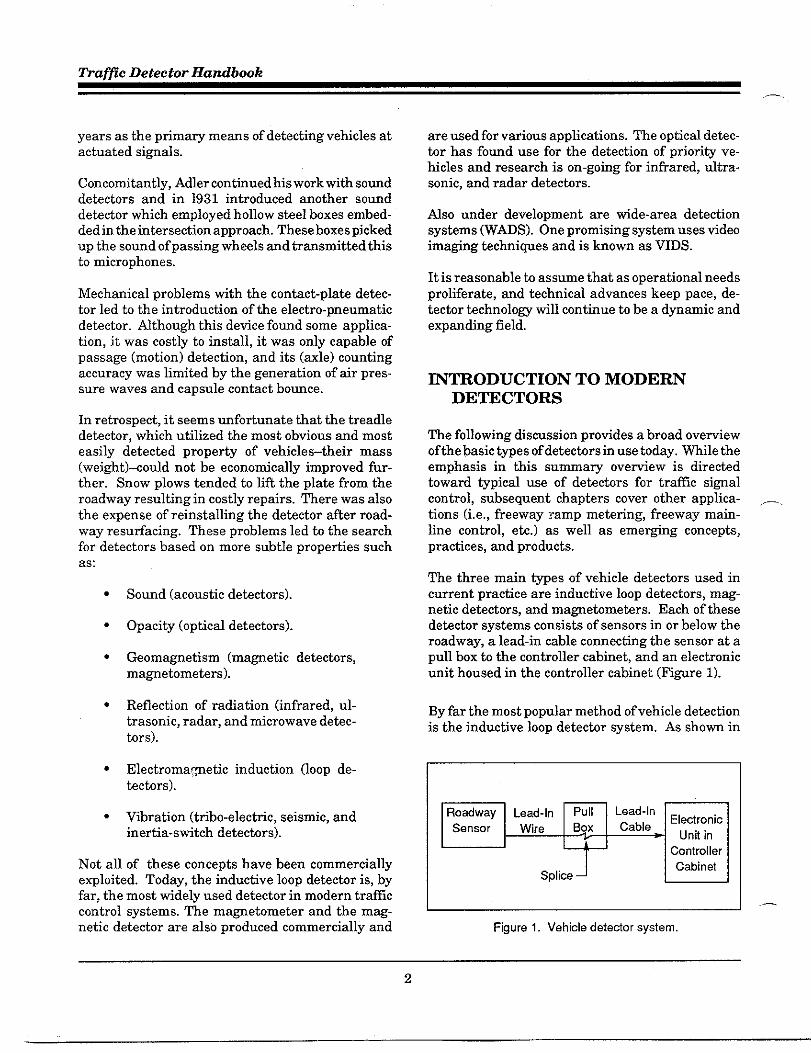
The three main types of vehicle detectors used incument practice are inductive 100Pdetectors, mag-netic detectors, and ma~ehmeters. Each of thesedetector systems consists of sensors in Orbelow theroadway, a lead-in cable connecting the sensor at apull box to tie controller cabinet, and an electronicunit housed in the controller cabinet (Figure 1).
By far the most popular method of vehicle detectionis the inductive 100pdetector system. As shorn in
—
.—
figure 1. Vehicle detedor system.
2

Intr&uction - ChaDter 1
Fi@re 2, the total system consists of three parts: adetector oscillator, alead-in cable, and a 100Pembed-ded in the pavement consisting of one or more turnsof wire. The detector oscillahr (ampfifier) trasmitsits own ener~ (electrical field) md operates on theprinciple that a vehicle resting in, or passing over,the 100Pwill mbalace a twed circuit resulting ina detection. The size, shape, and confi~ration oftbe100Pvaries considerably depending upon the specificapplication, rmgingfiom the most common size 6- x6-ft (1.8-x 1.8-m) 100PS,to longrectan~lar 100ps(6-x40- to 70- ft (1.8- x 12-to 21-m). Because of the flefi-hility ofits desi~, the 100Pdetectir provides for thebroadest range of vehicle detiction.
LOOPdetector systems are constructed with electri-cal characteristics that match an Oscillator/ampli-fier. The oscillator seines as a source of ene~ forthe 100P. men a vehicle passes over the loop or isstopped tithin the 100P area, it reduces the 100Pinductance, causing an increase in the oscillatorfrequency. The change in inductice or frequencyactivates a relay or circuit which sends m electricaloutput to the controller si~ifying that it has de-tected the presence of a vehicle.
The loop itself is constructed by cutting a slot in thepavement and placing one or more turns of tire inthe slot. The tire is then covered with sealant. h
Detetior Eletironics + yy,!l~~~p. . . . . . . .: Om
1 ‘ T“ ‘ “
24 ffController
Catineta 3 ft 6 fi. 3ft3n .6ft .,3c R,ead.i”.-A
~ =
I
Conduitc w
s Pull BOX
Loop saw-cut plan ~s Conduit to curb
:;
ao
alternate, more durable construction is to place theturns of wire in a plastic condtit just below thepavement sutiace. bother alternative is to encasethe tire in a plastic sleeve before installing in thesaw-ret slot in the pavement. A tide variety of loopsties and shapes may be used to meet specific needs(see Chapter 4). The 6-x 6- ft (1.8- x 1.8-m) squareloop is the most commonly used loop for actuatedtrfic si~d control.
Magnetic detector probes (Fi@re 3) are cylindricalin shape (no larger tha 2.25 in (57 mm) in diameteror more than 21 in (53 cm) in length) ~d are placedbelow the roadway. They detect vehicles based upona change in the lines of flu from the Eati’s mag-netic field. These detectors provide only passagedata and not occupacy or presence data. Accord-ingly, their use is limited to special circumsbncesand is being phased out of general use.
figure 3. Magnetic detector probe.
Ma~etometer probes (Fi~re 4) are small cylinders(no larger than 2 in (5 cm) in diameter or more thm4.25 in (11 cm) in length) embedded vetiically in thesuflace of the roadway. The presence of a vehicle isdetected by measuring the focusing effect of theEarth’s ma~etic field that occurs when the vehicleis near the detector. These detectors are patiicu-larly effective for use on bridge stmctures and withchronically poor pavement sutiaces. Magnetome-ters can be used instead of or in combination with100Pdetectirs.
bother device similar to the ma~etometer is themicroloop. It is a small, passive, cylindrical pmhefigure 2. Loop detetior system.
,3

-,
Traffic Detector Handbook
—.
.,. ., . .. . .. . . .. . . :., ,’,..,.
,, ,.
figure 4. Magnetometer probe
(0.ss in (2.2 ~) in diameter and 3.63 in (g.2 ~)Iong)buried beneath the roadway sufiace. A sampleprobe is shorn in Fi@re 5. It trasforms changes inthe Eatih’s mawetic field intensity into chmges ininductance. As a vehicle passes the microloop, thechange in inductance is sensed by a conventionalloop detector electronic unit.
figure 5. Microloop probe.
Other detector types thathavebeen used in the pastare still utilized in special situations. Radar detec-tors were quite popular in the fifiies and sixties, withmany installations still in etistance. A radar instal-lation is shown in FiWre 6. The sonic detector alsohad a period of popularity. It used the same prin-ciples as radar, hut in the sonic frequency rangerather than in the radio frequencies. A typicalsensor head (shown in FiWre 7) was mounted eitheroverhead or in a sidefire position. Both of these
figure 6. Overhead-mountedradar detetior.
types of detectors are being revived using moderntechnology (see Chapter 7).
The Hmdbook will concentrate on inductive loops,maWetometers, and ma~etic detectors. The main .-.emphasis is on detection for trafic si~al installa-tions. There is, however, a growing need for accu-rate, dependable detectors for tra~c surveillanceand control,
In reco~ition of the impotiance of accurate detec-tion in these applications, manufacturers have de-veloped new models that take advantage of ad-vanced technology. Others concentrate on develop-ing new detection techniques ad methodology.
figure 7. Sonicdetector sensor unit.
4

Introduction - Chapter I
n
DEF~TION OF TEWS
One of the major difficulties in explaining detectorapplication ad design theoties is the abundace(md redmdmsy) of terns used in current litera-ture. That is, a number of terns meaning the samething may be used interchangeably md indiscrimi-nately among various reference sources ad evenwithin a single document. This can create confasionfor even the most experienced traffic engineer.
TOavoid any potential confusion, the basic terminol-ogy used in this Hmdbook is defined below. Termsmeaning the same (or nearly the same) thing areappended for easy reference. TOthe extent possible,the tem shown in bold type was used consistentlythroughout the text. A more complete listing ofteminolo~ is inco~orated in the Glossaw at theend of the H~dbook.
Detecton A device for indicating the presence orpassage ofvehicles. This general term is usuallysupplemented with a modifier indicating type(e.g., loop detectir, magnetic detector, etc.);operation (e.g., point detector, presence detec-tor, etc.); or fmction (e.g., calling detectar, ex-tension detector, etc.).
Detector hplifie~ A device that is capable ofintensifying the electrical energy produced by asensor. AU example is a ma~etic detectoramplifier. A 100P detector unit is commonlycalled an amplifier, although its electronic fmc-tion actually is different.
Detector Uniti me potiion of a detector syetemother than the sensor md lead-in cable, consist-ing of m electronic assembly.
Lcrge ha Detector: (kea Detector) A detectoror series of detectors tired together in series Orseriedparallel covering m area in the approachtom intersection. Detection area varies from 6x 40 ft (1.8 x 12 m) h 6 x 100ft (1.8 x 30 m) orlarger. One of the more common confi~rationsis four 6- x 6- ft (1.8- x 1.8- m) 100PSspaced 9 or10 ft (2.75 or 3 m) apart for a length of 51 or 54fi (15.5 or 16.5 m).
P s-~ &ea De~C~E (point De~ctOr) A detectorthat measures the passage of vehicles past a
point (i.e., a small area usually not exceeding 6x 6 ft (1.8 x 1.8 m)).
Loop Detector Uniti h electronic detice which iscapable of energizing the sensor loop(s), ofmonitoring the sensor loop(s) inductance, and ofresponding to a predetermined decrease in in-ductmce tith m output which indicates thepassage or presence of vehicles in the zone ofdetection. It is the electronics package, exclu-sive of the loop(s) md lead-in cable.
Loop Detecto~ A detector that senses a change ininductmce of its inductive 100Psensor caused bythe passage or presence of a vehicle near thesensor.
WgneticDetecti~ Adetectorthat senseschagesin the EartKs ma~etic field that are caused bythe movement of a vehicle near its sensor. It isa vehicle detector placed under the roadwaywhich makes use of both the Earth’s mameticfield and the energy chmge created by the pas-sage of a vehicle over the detector to produce anoutput,
Magnetometer Detectom A detector that mea-suree the difference in the level of the earttisma~etic forces caused by the passage or pres-ence of a vehicle near its sensor. It is a deticecapable of being activated by the ma~etic dis-turbance caused by the passage or presence of avehicle. A magnetic flux generatOr/sensOr isinstalled in the roadway and connected to sensoramplifier electronics.
Passage Detecton (Motion Detector, DynamicDetector, Movement Detector) A vehicle detec-tor that has the ability to detect the passage of avehicle moving through the detection zone andto ignore the presence ofavehicle stopped withinthe detection zone.
Presence Detecto~ Atrtilc detector which is ableto detect the presence of a vehicle and hold thecall for a specified minimum period of time thatthe vehicle is tithin its field of detection.
Lead-In Wire (LOOPLead-In) That portion of the100Pwire between the physical edge of the 100Pand the pull bo% for a ma~etic detector andmagnetometer it is the wire which mns from thesensor (probe) to the pull box.
5

Traffic Detector Handbook
—
Lead-In Cablti (Feeder Cable, Home-Run Cable,TrmsmissiOn Line) The electrical cable whichseines to connect the lead-in wire to the input ofthe 100Pdetector nnit.
PdlBox (Hand Hole, Jmction Box, Jmction Well,Splice Box) A container usually at least 1 cubicft (0.028 cubic m) in size that is placed under-ground with a removable cover flush with thewound sufiace. Splices between lead-in cableand 100Plead-in wire are located here.
Crosstalk The adverse interaction of any channelof a detector unit with any other detector chsn-nel in that mit or another init. It is the mutualcoupling of ma~etic fields that produces aninteraction between two or more detector mitsin the same cabinet when the nnits are Operat-ing at similar frequencies. Crosstalk results ina detector outputting an actuation in the ab-sence of a vehicle.
Spkshovem h mwanted actuation caused by avehicle in a lane adjacent to that in which thedetector is located.
Zone of Detectiom (&ea of Detection, EffectiveLoop kea, Field of Influence, Sensing Zone)That area of the roadway tithin which a vehicleis to be detected by a vehicle detector system,
ORG~IUTION OF ~BOOK
This Handbook has been structured to parallel theprocession of decisions, activities, md functionsrelated to the desi~, installation, md maintenmceof detector systems. This introducto~ chapter dis-cussed the evolution of detector technolo~, thebasic types of detectors in use today, the emergingtypes of detectors under development, and the spe-cial terminology as it applies to this Handbook.
Chapter 2 protides the technical information basicto tbe theo~ of operation for the various types ofdetectors. It is specifically addressed to trti]c orelectric engineers tith responsibility for selecting orspecifying the proper detector design to meet spe-cific operational requirements. It also covers theroles of the NEW Standards and the Type 170Specification.
Chapter 3 provides an overtiew of detection applica-tions used in traffic control and identifies the widermge of choices involting operational features of thedetector component of trafic control.
Desi~ considerations in terms of detector confiW-ration and placement for the various applicationsare discussed in Chapter 4. It should be ofparticu-Iar interest to traffic engineers involved in develop-ing plms and specifications for local intersections,trfilc si~al systems, and freeway sumeillance andcontrol systems.
Chapter 5 stresses tbe importance of proper instal-lation procedures and describes the best current _practices. This chapter is primarily addressed toproject engineers, contractors, inspectors, field crewsupetisors, and trafic technicians.
Chapter 6 covers the broad spectrum of detectormaintenmce activities. It will protide general in-formation of value to management and supemisingengineers as well as detailed @idelines for mainte-nance supervisors and technician.
Finally, Chapter 7 protides an overtiew of newtechnology cumently under development in terms ofnew concepts, hardware, ad applications. It alsoincludes a retiew of relatively new products adapplications that have recently been introduced intigeneral usage. The GlossaW and List of Referencesfollow the appendixes which include supplementaltechnical information that may be of use by thosewho are interested in more detail.
6

2. DETECTOR TECHNOLOGY
This chaptir provides technical information basic tathe ‘%oti and awh~ detsctors work, including thetheoW of operation, the charactifistics of the road-way sensing element, and the functional character-istics of the various electronic wits for inductiveloop detictirs, maWeticdetectors, mdmagnetome-tirdetectors. Theinformation swmarizedin thischapter is intended to pmtide the practicing trtilcengineer or electrical engineer tith the back~oundneeded ta select the proper detectir design to meetspecific operational requirements.
Since its introduction in the early 1960s, the induc-tive loop detectir has become the most popular fomof detection system. The pfinciple components of aninductive loop detector system include one or moreturns of insulated loop tire wound in a shallow slotsawed in the pavement, a lead-in cable from thecurbside pull box @ the intersection controller cabi-net, and a detector electronics unit housed in theintersection controller cabinet. Fi@re 8 provides asimple schematic of m inductive 100Pdetector sys-tem model.
Simply stated, the detector electronics mit drivesener~ through the 100Psystem at frequencies in thenormal rage of 10kHz to 200 kHz. The loop systemfores a tuned electrical circnit ofwhich the 100Pwireis the indutiive element. men a vehicle passes overthe loop or is stopped within the loop, it decreasesthe inductance of the loop. This decrease in induc-tance then actmtes the detector electronics outputrelay or solid stite circuit which, in turn, sends animpulee to the controller unit si~ifing that it hasdetected the passage or presence of a vehicle.
This section describes in more dettil the 100Psystemtheo~, 100Pcharacteristics, md the basics of thedetector electronic init.
The basic DrinciDles of the inductive 100Ddetectorsystem di~cusse~ below are common ta“all of theinductive 100P system desi~s described later inChapter 4. In all systams, the loop wire and lead-incable possess a combination of resistice, induc-tice, md capacitance (both inter-wire and wire-to-eartb capacitive).
1 ENVIRONMENT
4 + + + 4induced Indutiive
PullbxLead-In Tuning
EletironicsVehicle Loop Cable NetworkCurrents
$
ReinforcingSteel Mesh
Hgure 8. Inductive Iwp detedor system model.
7
fiaffic Detector Handbook
Loop System Wsisbnw
Inductive loops, lead-in tires, and lead-in cablestypically use #12, #14, or #16 AWG tire with the lowfrequency or direct cument resistance in units ofohms.
This wire resistance is inversely proportional to thesquare of the wire diameter and increases as thetire diameter decreases. A Volt Ohm Meter (VOM)measures direct cument resistance. The tire resis-tance to alternating current increases as the fre-quency increases because the conducting area oftbewire demeases due to the non-uniform flu insidethe wire. This high frequency resistance cannot bemeasured with a VOM, but can he obtained from ameasurement of quality factor to be defined later.
The loop in the roadway also contains a inducedresistance (called the gmmd resistance) due totransformer action between the loop and inducedcument floting in the roadway and subgrade mate-rials. Appendix A provides a detailed derivation ofmound resistance. Table 1 protides DCflow fre-quenq resistance values for various commerciallyavailable loop wire md lead-in cables.
Table 1. Loop system wire DC resistance
Type Function DcManufacturer’s L = Loop ‘auge Resistance
Model # LI = Lead- In# AWG
Ohmslfi
94S8 L 14 0.0025
Loop hductace
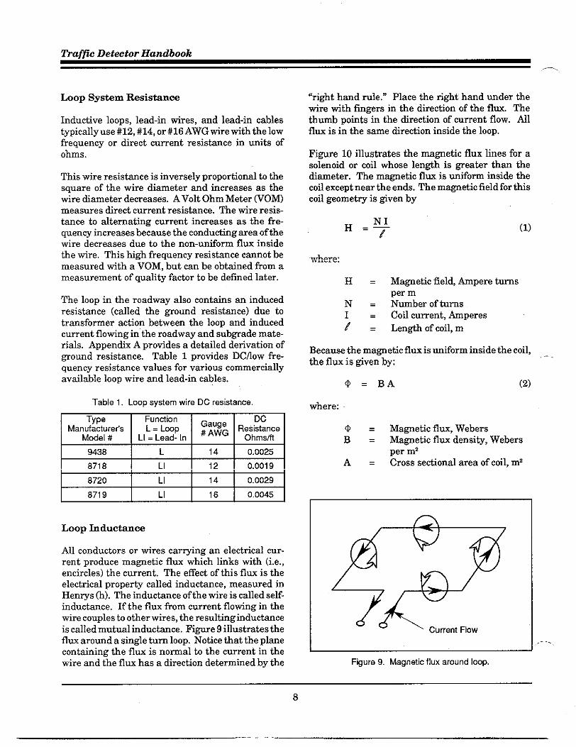
All conductors orwires car~ing an electrical cur-rent produce ma~etic flu which links tith (i.e.,encircles) the current. Theeffect ofthisflu is theelectrical property called inductance, measured inHen~s (h). The inductance of the wire is called self-inductance. Iftheflu from current flotingin thewire couples to other wires, the resulting inducticeiscalledmutual inductance. Pi~re9illustrates thefluxaromda single tumloop. Notice thattheplanecontaining the fluisnomal to the current in thewire and the flu has a direction determined by the
“righthandmle.” Place therighthmdudertbewire tithfingers in the direction of the flu. Thethumb points inthedirection ofcumentflow. Mlflu is in the same direction inside the loop.
FI~re 10illustrates thema~etic flux lines forasolenoid or coil whose length is ~eater tha thediameter. The magnetic flw is mifom inside thecoil except near the ends. The magnetic field for thiscoil geometry is given by
(1)
where:
H= Ma~etic field, hpere turnsper m
N= Number of turnsCoil current, hperes
;: Length of coil, m
Because the magnetic flux ismiform inside the coil,the flux is given by:
..-
O=BA (2)
where:
Q= Ma~etic flu, WebersB= Magnetic flu density, Webers
per m’A= Cross sectional area of coil, m’
Ifigure 9. Magnetic flux around loop.
8

Detector Technolo~ - Chapter 2
n
figure 10. Magnetic flux for solenoid (coil),
The magnetic flux density is related to the ma~eticfield by
Pr = Relative permeability ofmaterial (1 for nir)
PO = 4Z x 10-7, hperm
The inductance of a coil is defined as
~=~=NBAI I
where:
L= Inductance, hN= Number of turns1= Coil cwrent, Amps
(3)
(4)
The inductance ofa coil, tith a length much ~eaterthan the coil area to ensure uniform magnetic fluxinside the cofl, is given by:
This simple equation shows that cofl inductance isproportional to the turns squared and the cofl area,andinversely propotiional tocoillength. Nthoughtheinductance:fomula as written is not directlyapplicable to a roadway inductive loop, the formulacan be modfied by afactor Fl to account for non-unifom flux in the inductive loop.
(6)
This inductance fomula is applied to an exampleloop inductance calcdation in Appendfi B, Notethat /is called the “length of the cument sheet.” Therelative wrterm in the formula shows that iron witha relative M greater than one will increase the loopinductance. Athough the greatist increase in iti-ductance wodd occur when an iron core passesdirectly through the loop, the iron mass of a vehicleengine, transmission, or differential will slightlyincrease the loop inductance. This condition iscalled the “femoma~etic effect.”
Ferrom~etic Effect
Because of the phenomenon known as the ferro-maWetic effect, it is incomect to assume that it is themass of the vehicle that is causing the actuation.Actually, the heavy, femous engine in the loop in-creases the inductance. The insertion of an iron coreinto the field of any inductor acts to reduce thereluctance of the flu path and, therefore, increasethe net inductance. The peripheral meti of thevehicle has an oppositi effect due to the eddy cur-rents. The decrease in inductance from the eddycurrents more than offsets the increase from theferrous mass, and the net effect is an overall reduc-tion.
One of the advantages of the inductive loop detectoris the wide range of permissible geometries avail-able to the desiW engineer. These design optionsare discussed in detifi in Chapter4. The she and thenumber of turns of a loop or combination of loops,together with the length of the lead-in cable, must
9
Traffic Detector Handbook
produce an inductance within a range that is com-patible with the desi~ of the detector mit and tiththe goals of the desiW engineer. NEW (See Appen-dix J) specifies that a detector unit must he capableof operating satisfactorily over a range of 50 to 700Lh. Some units can accept much higher inductances;for example, from several loops wired in series.mile the higher inductances are technically fea-sible, NEMA has specified a consemative upperlimit to promote conservative practices.
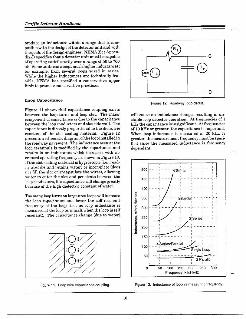
LOOP Capacitance
Fi@re 11 shows that capacitance coupling existsbetween the loop turns and loop slot. The majorcomponent of capacitance is due to the capacitancebetween the 100Pconductors and slot side wall. Thecapacitance is directly proportional to the dielectricconstant of the slot sealing material. Fi@re 12presents a schematic dia~am of the loop installed inthe roadway pavement. The inductance seen at theloop terminals is modified by the capacitance andresults in an inductance which increases tith in-creased operating frequency as shown in Fi@re 13.If the slot sealing material is hy~oscopic (i.e., read-ily absorbs and retains water) or incomplete (doesnot fill the slot or encapsulate the wires), allowingwater to enter the slot and penetrate between theloop conductors, the capacitance till change ~eatlybecause of the high dielectric constant of water.
TOOmany loop turns on large area loops till increasethe loop capacitance and lower the self-resonantfrequency of the loop (i.e., no 100P inductance ismeasured at the loop teminals when the loop is selfresonant). The capacitance change (due to water)
w“’”o”..+=:‘“o””’”.I.Q..!.
/ /
—
figure 11. Loop wire capacitance coupling.
oR~
E
o 0CpL~
figure 12. Roadwayloopcircuit
till cause an inductance change, resulting in un-stable loop detictor operation. At frequencies of 1kHz the capacitance is insi~ificant. At frequenciesof 10 kHz or Weater, the capacitance is important.men loop inductance is measured at 20 kHz or~eater, the measurement frequency must be speci-fied since the measured inductance is frequencydependent.
s ,,:,.. . ;...,, .,..:....... ;...
figure 13. Indudance of loop vs measuting frequency.
,-
—.
10

Loop Quality Factor, Q
The factor that measures the resonant efficiency ofa circuit is the “Q or quality factor. It is a dimen-sionless index. If the losses of the inductor are too~eat, the Q will be low. A petiect inductor has nolosses; that is, there is no dissipation of energywithin the inductor and the Q is infinita.
Ml of the energy losses in an inductor may berepresented by a resistor in series with the inductor.The ratio of the inductive reactance to the resistivelosses may be expressed as Q. Since inductivereactance is a frequency-dependent measure, thefrequency must be specified for a series circuit whenconsidering the pefiormance of an inductor. Theformula for Q is:
2n fLs w LsQ=~ =—
s Rs
where:
Q = Quality factorx= 3.14159 (a constant)f= Series inductance frequency,
HzLs = Series inductance, hR~ = Resistance, ohms
w= 2nf
(7)
The formula for the resonant frequency ( O. inradias) of the circuit in Fi@re 12 is:
‘0‘*Since:
QO R~W. =—
Ls
(8)
(9)
The formula for the quality factor, Qo, of theresonant circtit is:
(10)
In an inductive loop detector system, the circnit inFi@re 12 wfil have some load resistance, ~, shuntedacross the capacitor, CP,which will reduce the valueof ~.
The quality factor, Q ~, of the parallel circuit is:
Qp = wo Cp RL (11)
Since:
QO =oo CPRP (12)
mere R ~ is the transformed series resistancein parallel with R ~.
The loaded quality factor, Q, of the circuit inFi~re 12 with a load resistance, R ~, shuntedacross the capacitor, CP, is:
Q, QO‘= Qp+QO
(13)
The resonant loop quality factor. Q ~ , is reduced,.by the shunt load resistance, Ru A samplecalculation of loop system quality factor, Q, isshown in Fi~re 14,
In the case of loop detectors, it is recommended thatthe Q be fleater than 5. Moisture in the pavementand sub~ade can increase the loop ground resis-tance to the point that the Q of the loop system fallsbelow 5, thereby reducing the sensitivity of mostdetector units. Loop capacitance will also reduce Q.The oscillators in most detectors wdl not operatewith low Q,
The Q formula is intended for straight-forwardapplications in which losses are low, Q is high, andf, L, and R can be readfly measured. Detector loops,on the other hand, are not so clear-cut, as theinductance is distributed over the loop and lead-incable and is hard to measure. The Q.factor is furthercomplicated by the fact that the ~esistance of theloop wire and lead-in cable is larger than the seriesvalue measured with an ohm-meter, The extralosses are due to high frequency operation andground currents in the pavement associated withthe circuit confi~ration and the roadway environ-ment near the wire. The Q wfil vary from location tolocation.
11

Traffic Detector Handbook—
LOOP SYSTEM QUALITYFACTOR, Q, CALCULATION
Assumptions:
Loop Type: 3-turn, 6 x 6 ft (1.8 x 1.8 m) of #14 AWG wireLoop Inductance: 74@ at 20 kHz from Appendix CLoop Resistance (in air): 0.0025 Wft (.0083 am) frOmAppendix DLead-In Cable Type: 100 ft (30 m) of Belden 8718Lead-In Cable Inductance: 0.20 ~Wft (0.67 ~m) from Appendix DLead-In Cable Resistance: 0.0031 Wfi (0.0103 tire) from Appendix DOperating frequency 20 kHz
Total Loop System Series Inductance: 74@ +20 yh = 94 @Total Loop System Series Resistance: 0.25 Q + 0.62 Q = 0.87 ~
Note: Wire length for resistance calmlation is per wire (i.e., twicethe cable length).
Total Loop System Capacitance
Cp =+ =1
W. L~ (2Z * 20* 10 S)2 (94 * 104,
~ = 6.74* 10-’ Farad
@ality Factor of Loop System:
Q. = 13.54
This value is the unloaded loop system quality factor with 100 ft (30 m) of Belden8718 #12 AWG lead-in cable. Assume that the detector electronics adds a shuntparallel resistance of 1,000 ohms.
QO = W. ~ RP = (2n * 20 * 10~ (6.74 * 10-7) (1,000)
Q. = 84.70
The total loaded loop system quality factor is:
Qp Q.‘= QF+QO
_ (84.70) (13.54)- 84.70 + 13.54
Q = 11.67
figure 14. LOOPsystem quality factor sample calculation.
-,
-..
12

Detector Technolo~. Chapter 2
Tables 2 through 4 present calculated quality fac- and “finish” tires of the loop. Most manufacturerstirs. Loops operate at 20 kHz in these tables, tith recommend at least five turns per foot (16.5 turnsconductar andor quadmpole lateral spacing of 200 per meter).roils. Ml inductance and quality factors are appar-ent values (i.e., loop capacitance and resistice is in- The wire twists form small loops along the twistedeluded). wire which alternate in tinding direction. h exter-
nal ma~etic field from a noise or crosstalk sourceinduces voltages in the small loops which almost
Loop Lead-b Wtie cancel, thus reducing intefierence. The impotianceOf these t.tiete in the ]ead.in tire is stressed in-. .----- . .
The lead-in wire from the roadway loop to the pull Chapters 4 md 5. ~pical loop-to-pull box lead-inbox at the roadside is fomed by twisting the “start” tire characteristics are presented in Table 5.
Table 2. Rectangular loop parameters,”
WrsGauge
m
12
14
1 Turn
m
10 20
11 16
2 Turn
n
35 30
36 24
,4,, 63 12 89 14
16 11 12 37 18
18 11 8 37 13
“ 6x6 f00t(l.8xl.8m) loop ‘. Wth Iead<n able
WreGauge
m
12
14
16
18
3 Turn
=
73 37
74 30
L128 18
75 23
77 17
4 Turn
~
180 21
128 28
127 20
Table 3, Quadruple loop parameters.”
1 Turn 2 Turnlnduc - Quahty lnduc- Qualitytance Fatior tance Factor(yh) (Q) (Lb) (Q)
L17 22 60 33
18 17 61 27
18 13 62 20
19 9 63 14
3 Turn
m
125 40
127 33
129 26
130 19
(wh) I (Q)
123 43
125 35
4 Turn
z
211 46
213 38
216 30
217 22
5 Turn
m
184 47
186 40
L243 25
188 31
189 23
5 Turn
z
315 50
317 43
32o 34
323 25
. 6x6 fwt(l.8xl.8m) loop
13
—

Traffic Detector Handbook
Table 4. Circular loop parameters.”
[
(
. ; ,.”, ,.. , ,,,, .,.8,,.,=, l“”p
1 Turn 2 Turn 3 Turn 4 Turn 5 Turn
W re lnduc- Quahty lnduc- Quality lnduc- :::;y lnduc- Quahty lnduc- Quahty
Gauge tance Factor tance Factor tance tance Factor tance Factor
(AWG) (wh) (Q) (vh) (Q) (yh) (Q) (yh) (Q) (Kh) (Q)
12 10 20 34 31 71 38 120 44 179 49
14 10 16 35 25 72 32 121 37 181 41
16 10 12 35 19 73 24 122 29 182 32
18 11 8 36 13 74 17 123 21 184 24
. f.. . ,. . —, x- —---- ,---
Table 5. Twi3ed loop lead-in wires.
Wire JacketWire Insulation AWG
Number ofManufadurer Diameter Twists Indutiance Capacitance Resistance
Type Type number Mls per foot ~hlft pFlti Q/ft
XHHWCross tinked 14
Stranded130 3-4 0.24 10
Polymer0.006
High Density,—
Belden 9438 ~“,,,e+~,,,ano -..:!2.. 139 5.5 i 0.22 10 0.00252
Lead-In Cable In Appendix D, measurements of 100Psystem qual-ity (tith 100 ft (30 m) of shielded lead-in cable
The lead-in cabl; (home rm cable) frOmthe PU1lbOx connected to a loop) show that little benefit is gainedto the detector terminals in the controller cabinet is from usinglargerconductor diametersin the ebieldedcomposed of a shielded, twisted pair of wires. The lead-in cable. In other words, tbe decrease in qualityconducting shield reduces intefierence from exter- factor caused by using #14 AWG shielded lead-innal electric fields. Typical lead-in cable characteris- cable is not substitially reduced by substitutingtics are presented in Table 6. #12 cable. The principal loss results from the type of
Table 6. Commercial Iead;n able charadetistics
Cable Insulation Cable
ManufadurerWre Insulation AWG Diameter, insulation Inductance Capacitance Resistance
flvpe Type number Mils Tvpe ph I ft pF/ft Q/ft
Beldan
8718 Polyethylene 12 37 Wnyl 0.2 25 0.0019
8720 Polyethylene 14 32 Wnyl 0.2 24 0.0029
8719 Polyethylene 16 32 Wnyl 0.2 23 0.0045
Clifford
IMSA Polyethylene 12 30 Polyethylene 0.2 25 0.0016 ,—
Specification Polyethylene 14 30 Polyethylene 0.2 24 0.0025
50-2-1964 Polyethylene 16 30 Polyethylene 0.2 23 0.0040
14

shielding rather tha the conductir diameter. Table7 shows how lead-in cable type nnd length tiect thequality factor.
DE~-A~ON OF I~UCTAN~
There are several simplified formulas that pmtide%ule of thumb” approximations of the inductice ofa loop. However, more accurati inductin~e~ havebeen obtined by a mutual coupling method dis-cussed in Appendix L
This method protides acceptable accuracy for calcu-lating the self inductance of multi-turn, rectanW-Iar, quadruple, md circular loops which have alarge area relative to the conductir spacing. Themethod gives results that compare favorably with arange of measured loop inductances.
Appendix Cpresents the calculated loopinducticesfor various size loops and shapes (rectan~lar, quad-ruple, md circular). Inductance and quality facbr,for various turns of tire, are calculated using the
,,. .“.mutual coupl]ng Iomula.
hp~stemtidu-w ~&tiO~
Inductance of the lead-in cable is added to the loopinductance at the rate of22 @ per 100R (30m) of#14AWG lead-in cable. For example, a 6- x 6- ft (1.8- x1.8- m) rectan~arloop shoddhave three turns, ac-cording to Appendix C, ad will then have m induc-tmce of 74 @. If the lead-in is 200 feet (61 m) inlength, the total inductance till be:
L=74+~* 22=74 +44=lls@ (14)
If two or more loops are tired together in series,their inductances we additive. That is, L y L ~ +L2 f 2M, where M is the mutual inductancebetween the two loops md the si~ of M ispositive if flux is increased by the cumentflowing in the same direction in the closestspaced loop tires.
For a l~ge sep~ation the mutual inductance isnegligible, therefore L = L ~ + L2 (seriesconnection). Thus, series connection providesthe mtimum loop inductance.
Table 7. Lead4n ccble type and length effect on Q.
LOOP Lead-In Lead-In Cable Total Sefies Lead-In TotalTurns Cable Cable Wire
LoopParallel Loop Cable Seties Resist.
#l 4 Type Length Gauge Capac. I“d”fl. I“dufl. l“d”~,
AWG Belden (ft) (AWG) (NF) (#h) oh) @hj (:)
3 8718 100 12 0.674 74 20 94 0.253 872o 100 14 0.670 74 21 95 0.253 8719 100 16 0.670 74 21 95 0.254 8718 100 12 0.437 125 20 145 0.334 672o 100 14 0.434 125 21 146 0.334 8719 100 16 0.434 125 21 146 0.335 8718 100 12 0.312 186 20 206 0.425 872o 100 14 0.306 166 21 207 0.425 8719 100 16 0.306 186 21 207 0.42
5 6718 1,000 12 0.172 186 200 386 0.42
5 872o 1,000 14 0.160 186 210 396 0.42
5 8719 1,000 16 0.160 186 210 396 0.42
LOOPSize is 6 x 6 feet (1.e x 1.8 m)Frequency is 20 kHz ‘“ Measur@ Sedes resistance of loop 3 feet (0.9 m) above the Iaboratoy floor“ 8719 resistance value estimated
.ead-inCablelesist.
(:)
0.62
0.80
1.00
0.62
0.80
1.00
0.62
0.60
1.00
6.2o
6,00
10.00
TotalSeties?esist.
(n)
0.87
1.05
1.25
0.95
1.13
1.33
1.04
1.22
1,42
6.62
8.42
10.42
TLOOP Loop
System SystemQ Loadec
(1 ,000GQ
14 12
11 I 10
+
10 9
19 14
16 13
t
21 14
18 12
7 5
6 5
5 4
15
If the loops are tired together in parallel, then thecombined inductance is calculated from the fomula~ =VL ~+ l~2(parallel connection). FOrexamPle,two 6-x 6-R (1.8- x 1.8-m) loops of three turns each,connected in parallel give the folloting combinedinductance:
11~=z+L=274 74
(15)
2L=74and L=37wh
It is seen that parallel connection of loops reducesthe inductance. Care must be exercised to assurethat the inductance does not fall below the lowerlimit of 50 @ as is the case in the above example.
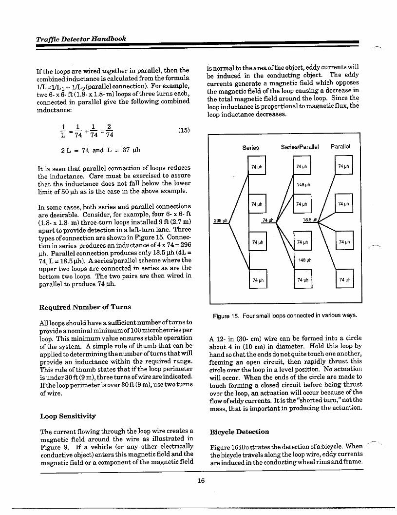
In some cases, both series and parallel connectionsare desirable. Consider, for example, fow 6- x 6- ft(1.8- x 1.8-m) three-turn 100PSinstalled 9 t (2.7 m)apati to provide detection in a left-turn line. Threetypes of connection are shown in FiWre 15. Connec-tion in series produces a inductance of 4 x 74 = 296@. Parallel connection produces only 18.5@ (4L =74, L= 18.5@). A seriedparallel scheme where theupper two loops are connected in series as are thebottom two loops. The two pairs are then tired inparallel to produce 74@.
Required Number of T-s
All loops should have a sufficient number of turns toprovide a nominal minimum of 100microhenriesperloop. This minimum value ensures stable operationof the system. A simple rule of thumb that can beapplied to determining the number of turns that willprovide an inductance tithin the required rmge.This rule of thumb states that if the loop perimeteris under 30 ft (9 m), three turns of tire are indicated.If the loop perimeter is over 30ft (9 m), use two turnsof wire.
Loop Sensitivity
The current flowing through the loop wire creates amagnetic field around the wire as illustrated inFi~re 9. If a vehicle (or any other electricallyconductive object) enters this ma~etic field md themagnetic field or a component of the magnetic field
is normal to the area of the object, eddy cuments willbe induced ia the condutiing object. The eddycuments generate a ma~etic field which opposesthe ma~etic field of the loop causing a decrease inthe totil ma~etic field aromd the loop. Since the100Uinductace is proportional to ma~etic flux, theloop inductice decreases.
Series Setie#Parallel Parallel
4<+
74vh 74 ph 74 Uh
>Mph
74 ph 74 vh 74 Ph
29S h 74 h 18.5 h
74 ph 74 ph 74 Mh
148 Ph
74 ph 74 ph 74 ph
figure 15. Four small loops connected in vatious ways.
A 12- in (30- cm) tire can be fomed into a circleabout 4 in (10 cm) in diameter. Hold this loop byhand so that the ends do not qtits touch one another,foming m open circuit, then rapidly thrust thiscircle over the loop in a level position. No actuationtill occur. men the ends of tbe circle are made totouch foming a closed circtit before being thmstover the loop, an actwtion will occur because of theflow of eddy mments. It is the “shotied turn; not themass, that is impotimt in producing the actuation.
.—.
BiWcIe Detection
Fi~re 16 illustrates the detection ofabiwcle. men “-the bicycle travels along the loop wire, eddy currentsare induced in the conducting wheel rims and frame.
16

Detector TechnoZo~ - Chapter 2
The eddy currents travel in m opposite directionfrom the loop currents, thus the dotted eddy currentma~eticfield opposes the loop’s maWeticfield. Theinductmce of the loop is reduced and detectionresults.
The loops ma~etic field is nomal to the conductingperimeter of the wheels ad frame. If the bicycletravels nomd to the loop tire, the magnetic field ofthe loop does not link the wheels and frame so noeddy cuments are induced and the bicycle is notdetected.
The ma~itude of induced current, and thus sensi-tivity, is propotiional to the cosine of the aglebetween the bicycle’s direction ad loop wire. Adiamond loop couples a nomal component of theloop’s ma~etic field to the bicycle (cosine 45°) re-sulting in detection at reduced sensitivity.
over the loop (m~imum sensitivity), all inducedinternal mesh cuments cancel, leaving a single in-duced cument floting aromd the perimeter of themesh which is equivalent to a single turn rectaW-lar wire loop or shotied turn. fignre 17 illustratesthis principle.
M~imum vehicle detection sensitivity results froma shorted turn with minimum distmce from the loopwires. As a consequence, the ideal loop should havea shape that approximates the vehicle’s periphe~.That is, a 6- x 6- R (1.8- x 1.8-m) square loop wouldbe preferable to one the size of an engine.
Because of mdercarriage height, high bed tmcksare most difficult to detect. The tidth of the loopshOuld he the width of the tmck if lane widthpemits. The length of the loop should not be lesstha the tidth or a loss of sensitivity till result.
figure 16. Bicycle detection
Detection with ~ctangdw or Sq~m Loops
A bicycle cm be considered a vetiical conductingtarget or object relative to the plane of the loop. Avehicle undercarriage is a horizontal target. Themdercamiage is modeled as a conducting rectmW-lar sheet of width and length of the vehicle at someaverage mdercamiage height.
The continuous sheet is approximated by a conduct-ing mesh. When the mesh is symmetrically located
Mutual hductance
Loop self inductance was defined using the loop’sma~etic flux. When the ma~etic flux of a loopcouples to a vehicle, the coupled flu is used h definemutual inductance.
FiWre 17 shows the ma~etic coupling between aloop md shorted turn, which is equivalent to a aircore transformer. The mutual inductmce betweenthe pfimary circait (loop) and seconda~ circuit(shotied turn) is given by:
(16)
mutual inductance betweencircuit one (loop) and circtittwo (shotied turn), h
Number of turns (1 for shotiedturn)
ma~etic flu normal toshorted turn area (Webers)
cument in loop (Amps)

tiafic Detector Handbook
—.
Hgure 17. Vehicle undercarriage model.
NO~~D LOOP ~UCTANCE(SENSIT~)
The loop sensitivity, S ~, of an inductive loop isdefined as:
LW - LvSL=lOO* L = 100* AL (17)
w
where:
L~= Inductance with no vehicleLv = Inductance with vehicle
The sensitivity, S ~, for the air core transformerof Fi~re. 17 and for a quality factor (Q) ~eaterthan 10 is given by
M:,SL = 100* K = 100* —Lll * Lzz
(18)
where
K= Coefficient of coupling
M21= Mutual coupling between loopmd shotied turn, h
Lll = Self inductance of loop, hL22 = Self inductance of shotied turn,
h
Assume the effect of vehicle iron is negligible.Then p. = 1 and the self inductance of theroadway loop is:
(19)
The inductmce of the shorted turn loop is, givenby:
20) -
18

Detector TechnoZo~ - Chapter 2
The mutual inductice between the sbotid tumloop ad roadway loop is @ven by
M21 GPONIN2AVFI
d (21)21
where:
Av = area of vehicle mdercarriaged21 = dishce between loop ad shorted
turn, m
The sensitivity is given by
(22)
where:
This formula shows that the sensitivity decreasesfor loop areas larger than the vehicle undercarriagearea.
The sensitivity decreases.asthe square ofthevehiclemdercarriage distance from the loop. The sensitiv-ity is also independent of the number of loop turns;however, pulling the tuns apart slightly increases
sensititi~ by increasing <at the apense of a deepersawmt slot in the roadway.
Appendix E shows a more complex fomula usefulfor calculation of S,. Fi@re 18 shows how loop sen-sitivity varies versus vehicle undercarriage heightfor 6-x 2- ft (1.8- x 0.6- m), 6- x 4- ft (1.8- x 1.2- m),and 6-x 6-ft (1.8-x 1.8-m) 3-turn loops. Note the lowsensitivity of the 6- x 2- R (1.8- x 0.6- m) loop.
Fi~re 19 illustrates how loop sensitivity decreaseswhen a 200- ft (60- m) lead-in cable is added to theloops in Fi~re 18. The 6- x 2- ft (1.8- x 0.6- m) loopwill probably double count a high-bed tmck.
FiWre 20 shows the decrease in loop sensitivity fora vehicle centered in 2-turn long loops. A futiherdecrease in loop sensitivity will result when a lead-in cable is added.
4.00
3501:-
1.0 1.5 2,0 2.5 3.0 3.5 4.0
Vehicle Undercarriage Height, feet
Rgure 18. Calculated sensitivity of 3-turn loops,
4.00
3,50 1---:---=
1.0 1.5 2.0 2.5 3.0 3.5 4.0
Vehicle Undercarriage Height, faat
Rgura 19, Calculated sensitivity of 3-turn loops with zoo ft(6o m) lead-in cable.
19

Traffic Detector Handbook
,,-
1.6o
1.40
1.20
1.00
0.80
0,60
0.40
0.20
0.00
!;:::=~—--4 --- ~——- -----
,!:!::,i!i::
–*-- ..-L.-–– 4---L -. -–!-----:\::;!:\::::
. ...-..:. - \_ >,. J . -- L --. —&— __ :-----
,:!::.. . . ..$ :;
‘..: > :. .. ..–.w–--.. -_.L. ––i--.. ~-...-..:.:!j
.,:!
:;::!:
1.0 1.5 2.0 2.5 3.0 3.5 4,0
Vehicle Undercarriage Height, feet
figure 20. Calculated sensitivity of 2-turn long loops
FiWre 21 shows that a loop over reinforcing steelmesh has lower sensitivity. The effect of the rein-forcing steel is modeled as a shorted turn at twice themesh spacing from the loop. The effect of thereinforcing steel is to reduce the ma~etic fieldaround the loop conductors (wire) which causes adecrease in loop inductmce md in sensitivity tovehicles. Table 8 presents the inductance for atypical 100Pwith and tithout reinforcing steel. mevalues are expectid to be consemative since themesh is assumed to be a petiect conduchr. Modemdetectors are capable of detecting vehicles eventhough the 100Pwire is ltid on the rebars beforeconcrete is poured.
Loop System Sensitivity
Loop system sensitivity may be defined as thesmallest change of inductance at the detector temi-nals that will cause the detectir to actuate. Thissensitivity must be equal to or ~eater than the
4.00 :
‘ ‘m~50 ...... .. ... ... ... .,
1.0 1.5 2.0 2.5 3.0 3.5 4.0
Vehicle Undercarriage Height, feet
figure 21. Calculated sensitivity of 6 x 6 foot loop overreinforcing steel.
detector threshold. Many States have specified thatthe detector unit must respond to a 0.02 percentchange in inductance. NEW Standards (See Sec-tion 15.3.2 of Appendix J), recognizing the differ-ences in detector unit desi~ (Am or AL), havespecified the sensitivity threshold for three classifi-cations of test vehicles when they are centered in asingle 6- x 6-ft (1.8- x 1.8-m), three turn loop with100 fi (30.5 m) oflead-in cable:
.
.
.
Class 1: 0.13 percent (Am) or 0.12~ (AL) inductance chmge (smallmohrcycle).
Class 2: 0.32 percent (Am) or 0.3@ (AL) inductance change (largemotorcycle).
Class 3: 3.2 uercent (Am) or 3.0 ~(AL) inducta~ce charige (auto).
h induct=ce in series or parallel with an inductive .—loop will reduce the 100Psystem sensitivity at thedetectir electronics terminals.
20

Detector Technology - Chapter 2
-
Table 8. Calculated effect of reinforcing steel on loopinductance.
Number Lwp Indudance, ~h
of Reinforcing Steel
Turns None I 1 inch 2 inches ] 4 inches
1 11 9 10 10
2 35 28 31 33
3 73 56 63 68
4 121 89 103 112
5 179 127 151 166
8 248 167 206 228
7 325 206 286 298
Sensitivi@ of Tmo Series Itiuctors
FiWre 22 shows how the loop sensitivity of twoseries inductors is expressed as an equivalent induc-tor. The equivalent total series inductmce, L~~, is:
,m. L~s=LA+~ (23)
The equivalent total series sensitivity, S TS,is:
[11STS=S:—~+L3LA
s: = Loop sensitivity as vehicleenters loop A
(24)
L-L7gure 22. Equivalent total series indudor sensitivity.
Sensitivity of Tmo ParazzezItiuctorc
Figure 23 shows how the loop sensitivity of twoparallel inductors is expressed as an equivalentinductor. The equivalent totil parallel inductmce,~p, is
(25)
The equivalent btaZ parallel sensitivity, S ~p, is
(26)
figure 23. Equivalent total p6rallel indudor sensitivity.
Si~Ze Loop Exampze
1. What is the loop sensitivity at the pull hoxassuming ahigh-bed vehicle (4- ft (1.2- m) undercar-riage) passes over the loop? Fi~re 24 illustratesthis case md shows lead-in wire len~hs. The circuitdia~am is show in ~~re 25. The sensitivity, S,,for a 4-ft (1.2-m) high undercamiage and a 3-turn, 6-x 6-fi (1.8- x 1.8-m) loop of #14 AWG tire is 0.1percent from Figure 18. The ttisted loop tires foman approximately 24-ft (7.3-m) lead-in wire to thepull box. The inductice per foot for #14 AWG loopwire with 5 twists per foot is 0.22 vtift. The lead-ininductance, L S,is:
Ls = (0.22 ~Wft) * (24 ft) = 5.3 ph (27)
—
21

Traffic Detector Handbook..—
LANE MARKERS
I
II
II
I
I I
1 I
Loop
I I
PullA
DetectorBOX Unti
)1 I
“ “ o
I Iu u o
1 I
I I
Rgure 24. Single Imp annected to pull hx.
The self inductance, ~, of a 3-turn, 6- x 6-ft (1.8-x1.8-m) loop of #14 AWG tire at 20 kHz from Appen-dix C is 74 @.
‘p=[-l=[,~%l= 0.093% (28)
Pull Detector
L2 BOX L5 Unit
~1
Q
figure 25, Single loop circuit
where:
S, = Sensitivity at the pull box, 7.
2, What is the loop system sensitivity at thedetictor teminals with a 200-ft (61-m) len@h ofType 8720 shielded lead-in cable between the pullbox and detector electronics?
From Table 6, the inductice per foot of type 8720cable is 0.22 utift. The total series inductancebetween the loop and the detector terminals is
L~ = [(0.22)* (24)1 +[(0.22) * (200)1 (29)
Ls = 5.3 ~h + 44 ~h = 49.3 ~h
~em
‘D=[%l=[l~*l -= 0.060% (30)
—
22

Detector Technology - Chapter 2
P
LANE MARKERS
I
I
I
I
I II , ILoop
LoopA 1 [ Pull Detedor Unit
BOX+
( )J,
I oI
“ o1 1
I I
where:
Rgure 26. TWO loops connected in seties.
SD = Sensitivity at detedorelectronic unit, 70
3. What is *e loop system sensitivity at thedetector teminals with a 200-ft (61-m) len~h ofType 8720 shielded lead-in cable between the pullbox md detector electronics ifa4-tum, 6- x 6-fi (1.8-,x 1.8-m) of #14 AWG wire is used?
The sensitivity, S., for a 4-ft (.1.2-m) high undercar-riage md 4-turn, 6- x 6-ft (1.8- x 1.8-m) loop is 0.1percent. from Appendix C, the loop self inductanceis 125 @ at 20 kHz. The series inductance is tiesame as in the previous case.
Therefore
= 0.072% (31)
ho hops in Series Example
1. What is the loop systim sensitivity at tiedetector teminals when a second identical loop isplaced in series tith the loop sensing the vehicle?FiWre 26 illustrates this case md shows lead-intire len@hs. The series connection is made in thepull box. Figare 27 shows the cirmit. The sensingloop is a 6- x 6-ft (1.8-x 1.8-m), 3-turn loop of #14
Pull Detector
Lz L3 L4BOX
kUnk
Rgure 27. TWO loops in series circuit.
23

Traffic Detector Handbook
,—
AWG. The self inductance of the series loop B is 74yh. The second (B) loops’ lead-in wire inductance is:
L: = (0,22 ~ft) * (12 ft) = 2.6 ~h (32)
The total series inductance of loop B and lead-inwire to pull box is:
L: = 2.6yh + 74@ = 76.6@ (33)
and:
(34)
= 76.8 + 79.3+ 47.6 = 203.7Wh
Then:
‘“=[-]=[1:%1= 0.066% (35)
fio Loops Connected in Parallel Example
1, What is the 100Psystem sensitivity at thedetector terminals with two identical loops con-nected in parallel? Fi~re 28 illustrates this caseand shows lead-in wire lengths. The circuit for thiscase is illustrated in FiWre 29. All parameters arethe same as the previous series example. Theprocedure is as follows:
L~s = LI + Lz (36)
(37)
Let:
LA= LI+L2 (38)
L~=L8+Li (39)
Then:
LA * LBLTP = LA + LB
(L, + L) * (L, + LJLI+LZ+LS+L1
and:
LA * LBL~=LTP+LS=~+LS
[
(L, + LJ * (L, + LJLD= LI+LZ+L3+L4
1+ Ls
Therefore:
‘D‘SL[*I*[l+-l*
I1
I
1Ls
l+(LI+LJ*(L, +LJLI+L2+L8+L4 1
(40)
(41)
(42)
(43) ..–
(44)
Wsonant Ckcuit
Many self-tuning loop detector electronics use theshift of frequency or period of an oscillator in theelectronics. The frequency determining the tmkcircuit of the oscillator is typically a parallel reso-nant circuit comprised of the equivalent loop systeminductance and detector tuning capacitance. Theequivalent loop system inductance includes the ef-fect of loop system capacitance and has an equiva- _lent quality factor due to system resistance losses, Ifthe equivalent loop systim inductance is too small,
24

Detector Technolo~ - Chapter 2
m
LANE MARKERS
1>!
~ ~/ KI
I I I
I ILoop
, ILoop Pull Detedor Unit
I 1 BOX
I ‘( : I —j I o
II I
v o1 1 1
I I I
+“ ~+’’+—’”20V *
figure 28. TWO loops connetied in parallel.
the oscillator till not oscillati. The range of loop The tuned tank circuit has a resonant frequencysystem inductance and minimum loop system qwl-ity factor is specified by the mantiacturer.
LzPull L5 Detector
BOX Unit
T
L4
L,
‘3rfigure 29. TWO loops in parallel circuit
calculated as:
‘D=2n~* ’45)
where L~, ~, and Q~ are respectively the induc-tance, capacitance, and quality factor of the tankcirctit.
It is clear from this equation that a decrease in theinductance will increase the resonant frequency mda quality factor geater tha five till have negligibleeffect.
DETECTOR ELEC~O~C UNIT
The electronic unit which generates the ener~ andmonitors the loop system has changed si~ificantlysince the 1970s. Early versions of loop electronic
25

Traffic Detector Handbook,—.
units were fixed-frequency units which used a crys-tal to produce a fixed frequency of oscillation. Therewere many problems with the c~sbl detectors, par-ticularly when used tith long lead-in cables.
&other serious problem was with resonant-fre-quenq drift due to environmental changes in tem-perature md moisture, These units were phased outof service in the 1970’s and were initially replacedwith analog phase shift detectors which were ca-pable of compensating for (or tracking) drift causedby environmental changes. Today, the commonlyused units include Digital Frequency Shifi Detec-tors, Digital Ritioed frequency Shift Detectors,Digital Period Shift Detectors, md Digital RatioedPeriod Shift Detectors. The desi~ theo~ of theseunits is described below. kalog Phase Shift Detec-tors are still in limited use for vehicle classification.
Analog Phase Shift Detector Unit
This unit was developed to meet the demands of theEuropean market, where bicycles must be detected.Like the cWstal model, it is a phase shifi detector,but uses two oscillators rather than one and theoscillators are variable rather than crystal con-trolled. The loop oscillator operates at a frequencydetermined by the loop and lead-in tire (in therange of25 to 170kHz). The loop oscillator is coupledto a second internal oscillator in such a way that theinitial, manual tuning procedure brings the twooscillators into synchronization in frequency andphase.
The tuning knob moves a femite core back and forthinside an inductor, causing the oscillator connectedto it to change its frequency (and phase) to matchthat of the loop oscillator. Artival of a vehicle intothe loop decreases loop inductance and the looposcillator attempts to pull out of synchronizationwith its companion oscillator. It is not able to do soin frequency because ofa cross-coupling resistor, buta phase shifi is developed that is the basis fordetection.
With this desi~ concept, the detector electronicunit is able to compensate for (or “track”) envi-ronmental drifi. As the temperature within thecontroller cabinet changes, the two oscillators driftidentically. The output of the two oscillators are fed
to a phase comparison circuit which develops a DCvoltage proportionate to the amount of sbifi; thus,the tem ‘analo< detectir, because it uses varyingvoltages rather than numerical comts.
When there are no vehicles tithin the detectionzone, the DC voltage is stored ad remembered by amemoW capacitor. When a vehicle causes a changein the phase comparator output, the difference be-tween it and the memoW capacitor causes relayoperation. VeW slow changes in the DC voltage arefollowed by the memo~ capacitor, which allows thecircuitto track for drift due to environmental changes.The memo~ circuit till ultimately forget a vehicleparked over’ the loop and drop that call. Detail ontracking environmental dfifi is included later under“Digital frequency Shift Detector Unit.”
Overview of Di~tal Detector Units
With the introduction of electronic digital process-ing techniques, most detectir electronic mit manu-facturers are cumently producing digital type ve- “—hicle detectors. Digital techniques allow more reli.able, accurate, and precise measurements than theanalog techniques.
Understanding how digital detectors operate isimpotimt because increased detector sensitivityresults in increased detector response time. A largedetector response time can result in si~ificant errorin vehicle velocity measurements using two loops ina speed trap (i.e., a measured distance). Responsetimes va~ with the different manufacturers.
Digital vehicle detectors sense either a change in thefrequency or period of a wavefom. Tbe oscillatorfrequency or period shifi is caused by a decrease inloop inductance when a vehicle is within the detec-tion zone. The detector oscillator frequency for aquality (Q) factor of 5 or fleater is:
f~ =1
2na(46)
where:.—
f~ = Detector oscillator waveformfrequency, Hz
26

Detector Technolo~ - Chapter 2
m
L~ = Total inductance acrossdetector terminals, h
CD = Total capacitive acrossdetector terminals plusinternal tming capacitance
The nomalized oscillator frequency chmge due to anormalized change in detector inductance for a Qfactor of 5 or ~eater is given by
MD 1 ALDT=–- 2 LD =-;% (47)
where
ti~ =
ALn =
SD =
Change in detector oscillatorfrequency, Hz
Change in detector terminalinductance, h
Sensitivity of detector toinductance change
It appears to be universally accepted that vehicleproximity to a buried inductive wire 100P pre-dominantly causes a chage in the loop inductanceparameter of the LC tank circuit fomed by the loop,lead-in cable, and detector input capacitor. Somemantiacturers use the percent change ofloop induc-tance, Am, while others simply use the change ofloop inductance, AL. Neither of these can be meas-ured directly at the loop input tcminals. However,to indicate sensitivity, several manufacturers pro-tide frequency metere to measure the resonantfrequency and the amomt of frequency change.
Experience has shown that the percentage change ofinductance (Am) from m unoccupied loop to an oc-cupied loop is extremely repeatable for a @ven 100Psize ad geomet~, for a given vehicle size andgeometry, and for a given location of the vehicle withrespect h the loop. Since parameters such as actualloop inductance ~d loop operating frequency do not
,fi affect Am and do affect AL, the following discus-sions and computations address the Am concept.The term “detector sensitivity,” in the context of this
discussion, is defined as the value of Am whichactuates the detector with the smaller values inter-preted to mean ~eater sensitivity.
For shoti lead-in cables with negligible series cableinductance:
where:
AL = Chage in loop inductancewhen sensing a vehicle, h
L= Loop inductance, h
(48)
s~ = Sensitivity of loop to vehicle
The period of the detector oscillator (T ~) is theinverse of the frequency. For a Q factor of 5 or~eater, the T~ is @ven by
where:
TD = Detector oscillator waveformperiod, sec
The normalized oscillator period change due to anormalized chauge in detector inductmce for a Qfactor of 5 or Weater is approximately
AT ~ 1 ALD—=-7 r=-TD
+ SD (50)
With the advent of sophisticated electronic digitalmicroprocessors and the availability of loop networkresonant frequency information at the detector in-put terminals, extremely precise measurements ofthe folloting parameters can he accomplished tithrelative ease:
● Frequency shift measurements (AfD)
. Gtioedfiequency shift measurements(Af~/f D)
21

Traffic Detector Handbook
—
● Period shifi measurement (Af ~/f ~)
● Ratioed period shift measurement(AT ~m ~)
Each of the four types of digital vehicle detictorsunits is introduced below. Detailed analyses andblock dia~ams of each type are protided in Appen-dices F through I.
Digital Frequemy Shift Detector Unit
This type of detector mit is not manufactured. Thetheory and characteristics of this detection principalare included to assist in the mderstanding of theoperation of the digital ratioed frequency shift detec-tor.
The digital processor of this detector concept com-pares counts proportional to oscillator frequencywhen sensing a vehicle to a reference count takenperiodically when no vehicles are present. Thereference comt is stored in a memo~. Duringvehicle detection, when the count exceeds the refer-ence count by a preset sensitivity threshold count, avehicle call is initiated.
The frequency shifi detector sensitivity, (S!),
from Equation 47 is:
Appendix F shows that:
(51)
where:
Nft =
Nfc =
Kf =
Fixed frequency thresholdcount selected by sensitivityswitch
Variable frequency countercount
Frequency sensitivity constint
In the above described method, the tem SD is pro-portional to the square root of the L~C~ product.Since larger values of SDrepresent decreased sen-sitivity, it follows that sensitivity decreases propor-tional to the square root of the L~C~ product titha Af~ measurement. Hence, eveW time the fre-quency switch is chmged to a new position (e.g. toavoid crosstalk), the sensitivity would change md, ifcritical, would necessitate a new setting of the sen-sitivity stitch.
With increased lead-in cable length, the added in-ductance of the lead-in cable would cause some lossof sensitivitymd the inmeased LDCD product wouldcause even more loss of sensitivity. Overall, thistype of measurement does not appear to he veryuseful.
Di@tal Ratioed Freque~y Shifi DetectorUnit
For this type of detector unit, the digital processorcompares counts proportional to the oscillator fre- —quency when sensing a vehicle to a reference counttaken periodically when no vehicle is present. Thereference count is stored in a memo~. When thecount during vehicle detection exceeds the referencecount by a preset sensitivity threshold count, avehicle call is initiated.
The ratioed frequency shifi detector differs from thefrequency shift detector because the frequencycounter is held approximately constant (see Appen-dix G).
The sensitivity, S:, is independent of the induc-tance, LD, and the capacitance, CD, across the de-tector teminals ad is calculated as follows:
2Nfts: =—N ~c (53)
where:
Nft = F&ed frequency thresholdcount
—
Nfc = Fixed frequency counter count
28

Detector Technolo~ - Chapter 2
From Appendix G, the measmement response timeis
2Nft~f=— (54)mf~S~
The advantage of hating the detector sensitivityindependent of the tiducknce and capacitance acrossthe detector teminals is illustrated by the follotingexample. (This example also applies to the DigitalRatioed Period Shifi Detector Unit discussed later.)
For this example, assume four equal size 100PS,say,6x 6 foot (1.8x 1.8m) tith an equal number of turns,say three. Wire the loops as follows (these confiW-rations are shorn in Fignre 15):
.
.
.
Ml series (288 @).
Seriedparallel (72 @).
Ml parallel (18 ph).
For simplicity, lead-in cable len~isnot considered.The sensitivity of the ratioed frequency or ratioedperiod shift detector is identical for all three of theabove titing schemes. Accordingly, a sensitivitythreshold sufficient to detect a small motorcycleover one of the four loops when tired in series neednot be chmged when rewired in series/parallel or allparallel.
Mthough lead-in cable length was not consideredabove, an extra long lead-in cable will produce vary-ing chages in inductance due to inductance shar-ing. The amount ofchmge depends on the length ofthe lead-in cable and the tiring scheme used for themultiple loops. Fignre 30 pmtides an indication ofthe si~al amplitude that may be expected at thedetector input terminals from a small motorcycletraveling over one of the four loops.
Di&tal Period Shifl Detector Unit
In the digital period shifi detector concept, tbe“perio& of a wavefom is the time required for onefull cycle. It is calculated by dividing one by thefrequency in cycles per second (CPS).me wit makesuse of a high-speed reference clock with a frequencyin the megahertz range to measure the loop periodprecisely in terns of the number of cycles from the
clock. That is, the count is propotiionalto the period.Precision is enhaced without sacrificing too muchspeed by actually measuring the time for 32 cyclesfor sensitivity one, 64 cycles for sensitivity two, etc.
When a vehicle enters the 100P,the inductice isdecreased, tbe loop frequency increases, and theloop period shortens. Therefore, there is a reductionin the measured time duration of a fixed number ofloop cycles. A reduction in the measured timeduration by an amomt ~eater than a preselectedthreshold value produces a output si~al (call) toindicate the vehicle’s presence. With careful choiceof reference clock frequency and the threshold value(4 comts f 2 comts), this desi~ is practical at fmyfrequency encomtered in practice. The time todetect is so short fiat it infeasible for the electronicsto sequentially scm or operate four small loops, oneat a time, several times a second. (Mul~ch~neloperation is dismssed later.)
The period shift detector is entirely self-tuning oninstallation and, like most other desiWs, is able totrack environmental drift. Like the digital fre-quency shift model, most models stop tracking for a
29
Lead-In Cable Length, feet
figure 30, Indutiance change as a funtiion of Ieadincable length.

Traffic Detector Handbook.—.
time after a vehicle enters the loop, to ~aranteethat the call of a small vehicle till be held longenough to bring the ~een to that approach.
The period shift detector
Equation 50 is:
Appendix H shows thati
p kmsensitivity, S ~,
(55)
(56)
where:
Npt =
Npc =
Kp =
Fixed frequency thresholdcount selected by sensitivityswitch
Variable frequency countercount
Frequency sensitivity constant
The term$
is inversely proportional to the squareroot of the C product. Because of the small valuesof S:, this represents increased sensitivity. It alsofollows that sensititityincreases proportional to thesquare root of the LC product with a AT measure-ment. Hence, with increased lead-in cable len@h,part of the 10SSof sensitivity due to the added lead-in cable inductace would be automatically compen-sated by the increase in the LC product. Unfortu-nately, the compensation is not one to one because ofthe square root relationship.
The detector response time (t ~ from Appendix His:
tp = 2Npt
f~ SDP (57)
Most vehicle detectors use a transformer to connectthe external detector loop teminals to the internalloop oscillator. If the transformers loosely coupled,a series leakage or swamping inductance results.
This inductance reduces the effect of lead-in cableson sensitivity at the expense of overall sensitivity.
If a swamping inductance, L ~, ie used in thedetector electronics, then:
tP = 2 NPt 2Npt[1+51 ,58)
“[ 1
1 ‘=fcs; — f~ s:
k1+ ~
For example, let
Npt = 4~ = 150~hL~ = 75@f~ = 2.22 mHz
s; = 0.005 %
Then:
[Z*4* ~+w
tP = 1(2.22 *106 HZ)*(5* 10-5) = 216ms (59)
The percentage emorinvehicle velocity obtikedfrom a speed trap using two spaced inductive loops isgiven by:
AV AT V—= ~oo*—v x (60)
where:
AVv=
Error in vehicle velocity, 7.
AT = Error in measured time, seesx= Spacing between leading edges
of the loops, feetv= Vehicle velocity, feetisec
The mmimum time error in vehicle speed or occu-pancy measurements is assumed to be the detectorresponse time. The speed trap emor caused bydetector reeponse times is illustrated by the follow-ing Wample.
30

Detector Technology - Chapter 2
Let:
AT = 2 * 216 ~~ = 432 m~ (o,432 ~e~)
v= 60 mph (96.6 kph) = 88 Wsec(26.8 tisec)
x= 100 feet (30.5 m)
AV = loo * (0.432)* (88)T 100 = 38.0% (61)
This example clearly indicates that the loop systemshould he desi~ed so that the system sensitivity isas large as possible. By using the detector electron-ics on a less sensitive r~ge, tie detector timeresponse is decreased, allowing more accmati ve-hicle speed detection.
A increase in the detector electronics clock fre-quency from 2.22 mHz to 22.2.mHz till reduce thepercentage velocity error from 38.0 percent to 3.8percent. Mauy of the newer detictors use clockfrequencies in the 20 to 25 mHz range.
Di@tal Ratimd Period Shifi Detector Wait
The digital processor of this type of detechr desi~compares counts proportional to the oscillator pe-tiod when sensing a vehicle to a reference counttaken periodically when no vehicle is present. Thereference count is stored in a memo~. men thecount during detection is less than the reference
cotit hy a preset sensitivity threshold comt, avehicle call is initiated. The ratioed period shiftdekctor d~ers from the period shift detector intiat the tireshold count, Npt is nOtfxed.
The threshold comt (see Appendk I) is @ven by
Npt = ST Npc (62)
Thus:
Sp _ 2 ST NpcD- Npc
=2ST (63)
Since the detector sensitivity is independent of theperiod counter count, tie detector sensititi~ isindependent of detector frequency. The responsetime is identical to that of the digital petiod sbifidetetior.
Compation of Digital Detectors
A summa~ comparison of the vatious detector elec-tronic unit concepts in terms of sensitivity andresponse time is presented in Table 9.
Multichannel Di&tal Models
Controller cabinet space carr be consemed if thedetector mit can operate more than one loop. Most
Table 9, Comparison of detetior sensitivity and respnse time.
Digital DetetiorDetector
Sensitivity DetectorType Res~nse Time
&mments
(SD)
Frequenq Shift s;=~~ Sensitivity is daceasad by an increase in indutiion fromtf = frame time the lamer loop or longer Iaad-in cable. Response time is
fixed by detetior frame time.
f% 2NftRat::[ Frequenq
tf=— Sensitivity is independent of indutiive value at detectorSD=~= terminals. Response time increases for increase in
mfDSfD indutiance at detector terminals and detetiorsensitivity.
s~=k ,,:-
Sensitivity is increased by increase in indutiive loop
Petiod Shiftfrom lamer loop or longer lead-in; however, availableindutive change is decreased when L ~ is present.
fcsg Res~nse time is dependent on loop inductance.
2N ~Ratioed Petiod Shift S:=2% Sensitivity is independent of induaive value at detectortp ==
terminals.
31

Traffic Detector Handbook
digital detector manufacturers offer detector witswhich can operate four or more loops. Some modelsaddress the crosstalk problem by providing a fre-quenW-separation switch, while others separate theloops by a time-ditision “scannin< process.
One mantiacturer’s scanning detector energizesand analyzes each of the four or more chmnelssequentially, one at a time, up to 100 times persecond. The digital period shift type of detechr isinherently fast enough to permit scanning. The timeto analyze a channel depends on the sensitivitydesired, as high precision in thresholding demandsmore time for counting reference pulses.
For example, if three 150 @ loops were connectedand used with sensitivities of 1, 4, and 6, and thefourth channel was stitched to off, then the fourchannels would require 2.3,9,63, and 0.9 ms respec-tively, for a total of 75 ms. Each channel would beener~zed ad analyzed a number of times per sec-ond calculated as 1,000 + 75 = 13. The use of loopsof larger L will reduce the scan rate, as till theselection of the highest sensivity settings on theunit.
If more than four similar and nearby loops areinvolved, the frequency switch can be used or thesize an~or number oftums of the loops ca be variedto provide crosstalk protection. Equation 39 mdTables 2, 3, and 4 can be used to desi~ frequencyseparations of 7 percent or more.
&other manufacturer utilizes a much higher clockspeed. This protides much faster scanning rates.For example, on the lower sesititity settings, thesample time is 0.5 ms per channel. Therefore, thetotal time to scan all four channels is 2 ms, MSO,when a chanel is stitched off, the the scan time forthat channel is zero.
Recent Advances in Di@tal Detectom
During the 1980s several refinements have beeninco~orated inh digital detector systems. Recog-nizing the hea~ demand on maintenance dollars,some manufacturers have added circuit~ to theirdetectors to reduce the frequency of trouble calls toreset detector mits attached to faulty loops. Thesefeatures, intended to reduce maintenance costs and
mmimize trtic petiomance, include Open LoopTest capability and Automatic and Remote Reset asdiscussed below.
Open bop Test Feature
This feature allows the detector to continue to oper-ate an intermittently open loop system. A momen-ta~ open caused by a broken wire, poor splice, orloose connection will be stored in memo~. If theconnection remakes, the uit till promptly retuneand continue to operate properly. If the open contin-ues, it till result in a constant call.
men inking a setice call to the intersection, thetechnician may obseme an indicator light that tillflash a distinct pattern if an “open” has occured. Or,on other brmds of detectors, the technicim pressesthe “Open hop Test” button on the detector mit todetemine whether an opening has occumed sincethe last semice call. The open loop memoW can bequeried repeatedly as it can be reset only by powerintemuptions (such as remoting the module from its —.card rack and reinserting) or by pressing the com-mon resetbutton on the detector. This constitutes asystem reset which will clear the open loop memo~.
Automatic Reset Feature
Some detectors can be pro~ammed such that, if acall (detector output) exceeds the pro~ammed time,the detector will generate an internal reset. Thisreset is controlled by the termination of the associ-ated phase geen. One agen~ claims that thisfeature reduced their detector maintenance costs by42 percent.
Remote Reset Feature
Remote reset allows automatic investigation ofsuspicious detector calls in computer or softwarepro~am control systems. A remote master monitor-ing tbe actuations of each system sensor may sus-pect that a detector is malfmctioning. By assetiingthe Reset command, the detector can frequently bereturned to nomal operation. The reset causes _presence calls to be cleared, but it does not clearOpen Loop Memo~ nor does it prevent m open loopfrom calling.
32

Detector TechnoZo~ - Chapter 2
[f the Reset fails to restore normal operation, thefault can be recoWized and printed out for mainte-nance attention. An open loop that is constantlycalling cm be taken offline so that it does not falselyinfluence system operating parameters.
Itiepen&nt Loop Faiz Output
In addition to the nomal detetior output, a secondoutput for loop status is protided on some models ofdetectors. ~enever the loop inductance takes astep change of+ 25 percent or more, the Loop FailOutput is turned on. If the inductance returns to avalue less thin i 25 percent of the reference, theLoop Fail Output turns off. This enables remoteintemogation of the loop status.
As with traffic si~al controllers, loop detectors weredeveloped md marketed by numerous manufactur-ers, each using a different type of harness connectorand detector technique. To overcome tbe subse-quent interchangeability problems, NEMA devel-oped a set of standards known as “Section 7. Induc-tive Loop Detectors” released early in 1981. Thissection of the NEMA Stidards defined functionalstandards, physical standards, environmental re-quirements, and intetiace requirements for severalloop detector mit confi~rations.
Section 7 covered only the basic fmctions associatedtith loop detectors. Users identified the need foradditional functions for specific locations, patiicu-larly delay md extension timing. To cover this gap,NEW developed, ad in 1983 released Section 11entitled “Inductive LOOPDetectors tith Delay mdExtension Timing.” This section was basically iden-tical to Section 7 tith the addition of requirementsfor tbe timing of delayed call ad extended callfeatures., A further revision resulted in a newSection 15 released FebmaW 5,1987 (reproductionis provided in Appendix J). This new standard com-Mnes, updates, md supersedes Sections 7 md 11.
De@ctor Unit Confi~ations
The NEMA Standards define two basic types ofdetector unit confi~rations: shelf mounted andcard-rack mounted. Shelf mounted detector uitsare commonly used in NEMA controller installa-tions, and are available in both single channel andmulti-chmnel (two or four channel) confi~rations.These shelf mounted units as shown in Fi~re 31 arepowered by tbe 120 volt AC supply in the cabinet.Outputs are generated by electromechanical relaysor by electrically isolated solid-state circtits. Physi-cal dimensions and connector requirements areincluded in the NEMA Standards in Appendix J.
Card-rack mounted detector units, illustrated inFi~re 32, fit into a multiple card rack and operate
figure 31. Shelf mounted detector units Bgure 32. Card-rackmoutieddetectorunits
33

Traffic Detector Handbook
off an external 24 volt DC power supply generated inthe rack assembly or elsewhere in the controllercabinet. Use of these devices are an effective way toreduce cabinet space requirements” where largenumbers of detectirs are needed.
Modes of Operation
There are two modes of operation selectable for eachdetector chanel: presence md pulse. Presencedetection implies that a detector output till remainon while a vehicle is over the loop.
NEMA Standards require the detector unit h beable b sustain a presence output for a minimum of3 minutes before tuning out the vehicle. Most ~itswill maintain the call for periods up to 10 minutes.This mode is typically used with long loop instilla-tions on intersection approaches with the controllerin the non-locking detection memo~ mode.
Non-1ocking detection memo~ is a controller fmc-tion whereby the controller retains a call (vehicledetection) only as long as the presence detedor isoccupied (vehicles are passing over or stopped on thedetector). If the calling vehicle leaves the detector,the call is dropped (forgotten) by the controller.
Pulse detection reqtires the detector to generate ashort pulse between 100 and 150 ms) every time avehicle enters the loop area. This mode wouldtypically be used where detectors are located wellupstream of the intersection with the controller inthe locking detection mode. That is, the vehicle callis not dropped by the controller when the callingvehicle leaves the detector. For more information onthese modes, see Chapter 3.
Output ~pes
TWOtypes of outputs are available for detector units:relay and solid state. Relay type outputs use electro-mechanical relays to generate a circuit closure adthus, a detection call to the controller. Solid-stite,outputs have no meting parts, and are thereforegenerally more reliable and considerably more accu-rate in tracking the actual presence ofvehicles. Thisis a ve~ impotiant factor in some aspects of timingtraffic signals.
The relay type outputs are desi~ed to ftil “on”(contacts closed) when power h the detector is inter-rupted. The solid state output fails “off’ (non-conducting) in the same circumstances, Therefore,a relay type output may be more desirable for usetitb intersection actuation because a constant-callwould be safer than the no-call situation, and a solid-state output more desirable where accurate pres-ence detection is desired.
Cmsstik
Men two loops are the same size ad have the samenumber of turns and the same lead-in length, theyhave the same resonant frequency. Should thesetwo loops be near each other or should the lead-insfrom these loops be in close proximity (perhapsinning in the same conduit), a phenomenon knowas ‘crosstalk” can occur. This occurrence is anelectrical coupling between the two loop chanelsand will often manifest itself as brief, false andorematic actuations when no vehicles are present. _,
NEW Stidards reqtire some mems to preventcrosstalk, either inherent, automatic, or manual.The most common feature is a frequency selectionswitch used to vary the operating frequency of theadjacent loop channels.
Timing Features
As contained in Section 15 of the NEW standards(Appendix J), the timing features include delay andextension timing. Delay timing can be set from Oto30 seconds, indicating the time which the detectorwaits, horn the stati of the continuous presence of avehicle, until an output begins (see FiWre 33). Theoutput teminates when the vehicle leaves the de-tection area. If the vehicle leaves the loop before thedelay time has expired, no output is generated.Extension time, defines the amount of time theoutput is extended after the vehicle leaves the zoneof detection (see RWre 34), and can be set from Oto15 seconds.
Timing features can be controlled by external inputsto the detector. For detectors with relay type out- ‘puts, a Delay~xtension Inhibit Input is pmtidedand reqtires 110 Volts to activate. Detectors tith
34

DelayOperetion- OutputOccurs-l Xme Set %
(Present ------
Vehicle ((Not Present
(Concluding
[NotCond..ti”g ‘=output (
Delay Operation - No Output Occure
(Present
Vehicle ((Not Present -=
(Conduting ----------------- .
output ((Not Conducting
figure 33. Delay operation.
,m.
solid state outputs have a Delay~xtension EnableInput, which reqtires a ‘1oW stite DC voltage (Oto8 Volts).
A typical delayed call installation might be a semi-actuated intersection tith heav righ~tums-on-redfrom the side street which has long loop presencedetection. Using a relay output detector, the sidestreet Ween field output (110 Volts AC) is connectedto the Delay~xtension Inhibit input. Thus, a delayis timed, alloting right-turns-on-red to be madewithout mnecessarily calling the controller to theside street. (Hea~ fight-turn movements will bring
+ Tme Set(Present ----
Vehicle ( r(Not Present
(Conducting ----
(NotCondu.ing~output (
Rgure 34. Etiension operation.
up the ~een anyway, as tie 100Ptill be occupied hyfolloting vehicles.) However, when tie side streethas the Ween, the delay is inhibited, permittingnomal extensions of the Ween.
Conversely, extended call detectors could be used onhigh-speed approaches to an intersection operatedby abasic (non-volume-density) actuated controller.Using this technique, the apparent zone of detectionis exknded, and a different “gap” ad “passage” timecm be meated without the volume-density controls(this does not, however, replace volume-densityfmctions). The Delay/Extension Enable Input on asolid-stute output detector could be tied to thecontroller’s “Phase On” output (Wf. 1).
TYPE170 SPEC~ICA~ON
Simultmeously with the evolution of the NEWStindards, the S~tes of California and New Yorkdeveloped the Type 170 controller specification. Aetiti the NEW Stsudards, tie development of thisnew controller was a direct response to the problemsof non-interchangeability. The system developedwas to be interchangeable between all mmufactur-ers suppling equipment for either state.
Unlike the NEW Standards which stmdardizefundions, the Type 170 Specification standardizeshardware. The Type 170 is defined as a systeminvolving cabinet, controller, md Al required acces-sories including detectors. The California system(figure 35) specifies a large, base-mouted cabinettith full component layout for 28 two-chanel detec-tor mits, while the New York system features asmaller, pole-momted cabinet tith 14 two-chaneldetedor units. New York has subsequently retisedits specification to reqnire a new microprocessor.This system, labeled a Type 179, covers the samecabinet and detectors as the original Type 170.
Ae the Type 170 Controllers arehousedin standard-ized cabinets, all components are modular or cardrack-mouted. The detector sensor unit is mountedon a edge-connected, printed circuit board. Twochrmnel detectors tie up one card slot, four channeldetectors take two slots. The detector modde frontpmel is provided with a hand pull for insefiion andremoval from the input file.
35

Traffic Detector Handbook
I BLANK I
170
CONTROLLER UNIT
; !1 INPUT FILEDUALCHANNE[DECTECTORS
~1 (LOOP,MAGNETIC0(MAGNETOMETER)01
1.> >USH RELAY
.FLASHER
.DUPLEXRECEP.
6 LOADSW2 FL,TRANSFERREMYS
6 LOADSw2 FL.TRANSFERRELAYS21oMONITOR
Hgure 35, Type 170 catinet layout (Cahfornia).
Model 222 / 224 Loop Dekctors
Chapter4 of the Type 170 Specification (reproducedin Appendix K) defines the specification applicableto the Model 222, Two-Channel Loop Detector Sen-sor Unit and Model 224, Four-Channel Loop Detec-tor Sensor Unit (See Figare 32). Specifically, thischapter sets forth the general description, fwc-tional requirements, md electrical requirements.
Each detector chmnel is equipped tith panel se-lectable sensitivity settings for both presence andpulse modes of operation. As with the NEW Sti.dards, the Type 170 Specification requires somemeans h prevent crosstalk with other modules. Italso reqtires that the detector channel shall not
detect meting or stopped vehicles at distances of 3feet or more from any loop perimeter. The timingfeatures are inco~orated into the various Type 170software programs such as the Caltrms Local Inter-section Program (LIP).
SELECTION FACTORS
There are several imporbt considerations thatshould be evaluated before selecting a appropriatedetector mit model. The importice of these factorsdepend on the particular requirements of a givensituation.
Tuning finge
NEMA reqtires that a detechr unit he capable oftuning md operating as specified over a range ofinductance from 50@ to 700@. For most applica-tions, this rmge is adequate. Some wits, however,are capable of tuning and operating over a range of1@ to 2,000 ~. ~is larger operating range pemit —extra long lead-in cables mtior several loops b betired in series to one init.
Response Time
The time required for a detector unit to respond tothe arrival and departure of a vehicle is of impor-tance when the output is used to calculate speed andoccupancy. Systems for the sumeillance and controlof sutiace street trfic siWals ad freeway flowusually perfom these calculations.
If the time for vehicle call pick-up is close to the timefor drop-out, little or no hiss in the time of vehicleoccupancy is introduced. If there is si~ificantdifference, but the difference is about the same fromwit to mit, a correction for the bias is easy to apply.
NEMA specifies that a detector unit respond to thearrival or departure of a small motorcycle into andout of a 6- x 6-R (1.8- x 1.6-m) loop within 125 ms. hautomobile call must be initiated or teminatedwithin 50 ms. NEMA also states that for cefiinspecific sumeillmce applications which involve ._vehicle speeds in excess of 45 mph (72 kph), moreprecise response times might be required.
36

Detector Technolo~ - Chapter 2
It should be emphasized that response time is be-coming more impotiat. mat the user accepted inthe past, was speed md occupancy measurementsthat averaged out over many vehicles to a marginalaccuracy. Now, and in the future, more emphasis isbeing placed on faster responce times to protide~eater accuracy to meet the needs of advacedtraffic control algorithms. Many of the maa@actur-ers are responding to this need by supplying newmadels with enhanced capabilities.
A study pefiomedforthe SCANDI project in Detroitfomd that the duration of a call is impacted by theheight of the flu field, which, in turn, depends ontbe presence md depth of reinforcing steel and otherlocation-specific factors (Ref. 2). The study indi-cated that adjustable, diamond-shaped loops com-pensate for such factors at each location, resulting ina uniform duration from loop to loop for a givenvehicle at a given speed.
Recovery horn Sustxined Occupancy
Recove~ time can become critical when the unit isoperated in the presence mode tith along 100P,say6-x 50-ft (1.8-x 15-m), at the stop line, or four 6-x 6-ft (1.8- x 1.8-m) loops in a left-turn lme wired in acombination of series/parallel. NEW requires thatafter a sustiined occnpancy of 5 minutes by any ofthe three test vehicles, the detector shall recover tonormal operation at least 90 percent of the mini-mum specified sensitivity within one second stirthe zone of detection is vacated. If a detector uitdoes not recover qtickly enough, the next vehiclemay not be detected at all and will be trapped wtila new vehicle arrives on the loop.
Loss of Detection dnring Satwated mow
During peak periods, a long loop or combination ofloops maybe held in detection titbout abreak for mhour or more. In these sitwtions, it is impotiantthat the detector mit be desi~ed to continue out-putting for at least an hour tithout dropping thedetection because of an environmental trackingfeature or other desi~ defect. NEW does no:address this importint point.
SmrsitititytithPxvmnent Wer%
Depth of loop wires has traditionally been consid-ered to be a critical factor when the pavement isoverlayed. However, tests conducted in Texas sug-gest that, with high sensitivity, proper installation,md calibration, the depth at which a loop is buriedshould have little effect on auto detection. In thesetests, a 6- x 6-ft (1.8- x 1.8-m), 5-turn 100Pwas bufiedat a depth of 18.5 in (50 cm) md encased in a U2-in(1.2-w) PVC condtit with no filler. There was nOappreciable difference in the detection of ]~ge carsbetween the near-sufiace mounted loops and thedeep buried loops.
Bicycle detection was only slightly less eficient withdeep buried loops. The difference occurred at themedium sensitivity setting. The sufiace 100Pde-tected the bicycle 1 ft (0.3 m) outside the loop at themedium setting, while the deep buried loop did not.The rectan~lar 6- x 6-fi (1.8- x 1.8-m) did not detectbicyclesin the center potiion of the loop on either thesurface momted or deep buried loops regardless ofthe detector setting.
Pdse-Mode Reset
The pulse mode of operation provides an output (100to 150 ms) that is useful in counting vehicles. Adetector unit should be capable of resetting or re-phasing correctly to avoid either overcouts orwdercounts mder cetiain conditions. NEW re-quires only that a detector produce one, and onlyone, output pulse for a test vehicle meting at 10 mphin the detection zone ofa6- x 6-ft (1.8- x 1.8-m) loop.
For users tishing to comt vehicles in two or morelanes at the same time, a separati detector and loopis recommended for each lane to ensure accuracy.This approach can be implemented for a small addi-tional cost over the use ofa single detector and a wideloop.
Operation with Grounded or Open Loops
Mthough NEW does not address this point, somedetecto~sprotideftilstie operation tith~aultyloop~i.e. grounded or open 100PS. The use of a 100P
37

fiaffic Detector Handbook—.
isolation trmsfomer pemits these models to oper-ate if the loop insulation is leaky or even sho~dcompletely to growd at a single location.
Isolation allows %alanced to Womd” operation ofthe loop circtit. This reduces the effect of the loopand lead distributed capacitance and hence theeffects of thermal ad moisture changes in the ca-pacitance. The balance also minimized loop cirwitcoupling from lead-in cables in common condtits. Ifthe loop breaks, this design will fail in a “safe” waybyholdinga conshnt call, thuskeepingtr@cmotingad avoiding trapping ay vehicles. Such operationis, however, ve~ inefficient.
Lightning Damage~leotiml Intefiemnce
k extensive study into the effects of lightningrelated electrical surge problems was conducted bythe Ontario Minist~ of Transpotiation ad Com-munications (Ref. 3). The major conclusions of thestudy were
● Most problems occured on common~omding systems.
● If changed to isolated grounding,maintenance problems are reducedalmost 80 percent.
● If system using isolated grounding isalso up~aded to include both primaryand seconda~ surge protection, main-tenance problems are reduced by morethan 90 percent.
NEW reqtires that detector units tithstmd thesame power-line trasients specified for controlleruits. The detector loop input teminals must beable to withstand 3,000 volts. The primary to secon-da~ insulation of the input (loop-side) transformerprotects against “common mode” lightning voltages.
With one model, differential lighting protectionconsists of a four-element protective circuit cOm-posed of the input resistors, the neon tube, tbetransformer leakage inductance, and the diode pathacross the seconda~. Differential lightning-inducedcuments are also potentially damaging. These cur-rents are shunted through the neon bulbs, limitingthe voltage across the transformer.
In Model 170 contoller cabinets, the specificationsrequire lightning protection be instilled within theloop detector init. The protection is to enable thedetector to withstmd the discharge of a 10 micro-farad capacitor charged to t1000volts directly acrossthe detector input pins with no loop load present.The protection must also withstand the discharge ofa 10 microfarad capacitor charged to MOOOvoltsdirectly across either the detector input inducticepins or from either pin to earth ~ound. The detectorchasis is grounded md a dummy resistive load of5.Oohms is attached to the pins.
The Model 170 specifications also include provisionsfor preventing intefierence between chmnels in agiven unit as well as between units. The preventionmeaus may be either manual or automatic.
WG~TOMETER DETECTORS
The magnetometer consists ofa small in-road sensorabout the size and shape of a small can, a lead-in —cable, and an amplifier. A typical installation isshown in ~Wre 36.
The magnetometer detector was introduced in the1960’s as an alternative to the loop detector in spe-cific situations. It is a special type of maWeticdetector desiWed to detect the presence of a vehicleby measuring the focusing effect of the Earth’sma~etic field which results when ferrous metal(e.g. the vehicle) is in the ticinity of the detector.
The ma~etimeter is nomally used where the onlyinformation required is that the vehicle has amivedat a “point” or small-area location. Therefore, it isused to actuate controller phases operated in thelocking detiction memo~ mode. It is also effectivein counting vehicles. Unlike the 100Pdetector, themagnetometer will usually work on bridge deckswhere steel is present and cutting the deck pave-ment for loop installation is not pemitted.
The ma~etometerprobe and its lead-in wire (whichis polyeurathme jackted) tind to sumive in cmmblypavements longer thm ordina~ loops. In addition,they require fewer linear feet of saw cut. Both ..-ma~etometers and loop detectors have their re-spective applications md tend to complement eachother.
38

Detector Tmhnoto~ - Chapter 2
-
~-it*~*
Normally 1 in. deep
t
Pull boxes forsp~cing probecable to lead-incable
Hgure 36. Typical magnetometer installation
MODEL 228 ~G~TO~~R DE~CTOR
Chapter 6 of the Type 170 Specification (see Appen-dix K) addresses specifications applicable to theModel 228 two-channel magnetometer detectorcontrol unit ad the Model 227 magnetometer sens-ing element. The magnetometer control unit isspecified only in the two chmnel version. Eachchmnel operates tith from one to six probes orsensors (Model 227). The control wit produces moutput signal whenever a vehicle passes over one ormore of the probes.
A magnetometer measures the passage or presenceof a vehicle. Two modes of operation are provided:pdse mode which gives an output closure of 125 t 25ms for each vehicle entering the zone of detection,ad presence mode which gives a continuous outputas long as a vehicle occupies the zone of detection.
~ORY OF OPERA~ONS
The Eatih is a large bar magnet tith lines of fluxrmningfrom pole h pole as show in Figure 37. For
\ = j EARTH IS uRGE SARWGNET
Hgure 37. Eatth’s magnetic flux lines.
39

Traffic Detector Handbook—
a vetiical axis maWebmeter to function, the vetii-cal component of the Earth’s ma~etic field mustexceed 0.2 oersteds; therefore, vertical As maWe-tometers cmnot be used near the equator where themaWetic field lines are horizontal.
Figure 38 presente a map of the mgle of the earth’sma~etic field md defines the area (crosshatched)which is not suitable for using ma~etometers
A vehicle of iron or steel distorts the flux linesbecause ferrous material is more permeable h fluxlines than is air. That is, the flu lines prefer to passthrough the femous vehicle. As the vehicle movesalong, it is always accompanied by a concentration offlux lines known as its “maWetic shadow as illus-trated in Figure 39.
There is reduced flux to the sides of the vehicle, mdincreased flw above and below it. A maWetometerprobe instilled within the pavement detects theincreased flux below. Vehicles traveling betweenzero h 100 mph (Oto 160 kph) can be detected.
PROBE C~C~~STICS
A typical ma~etometer probe is cylindrical andapproximately 1 in (2.5 cm) by 4 in (10 cm). It isinstalled in a dtilled hole in the pavement generallyabout 1-R (0.3-m) deep. A general amangement ofthe components of the ma~etometer probe is shownin Figure 40.
The core and the windings comprise a small, stable,trmsfomer-like element. It consists of sets oftindings placed over a core material that has beentreated to obtain special saturable magnetic proper-ties. The core is a stigle strip of Pemalloy, aroundwhich are mapped ptima~ md seionda~ wind-ings.
The operation relies on the second-hamonic tech-nique applied to a open saturable core which isoriented so as to be sensitive to the magneticdisturbances in the Earth’s ambient maWetic field.A triangular wave excitation current of suitable
—.
.—
Rgure 38. Equatorial belt not sutiable for veflical wis magnetometers.
40

Eati,s magnetic flux knes
or steel)ine
w, SUdam
ensiV around _ _ - _
‘Mde-=:m=: —-- ——— — — —
Vehicle will focu:the magnetic fiel(flux tines) thru Uveticle
?Increased flux densi~akve & below vehicle
$ 1
im~
WSITIVE
+1
~L_---Lv
NEGATIVE
figUre 39. Veticle’s magnetic shadow.
frequency (typically 5 kHz) is applied to the twoprima~ windings connected in seties opposition.The seconda~ windings, which also car~ the DCbias to neutralize the ambient field, are connected inseries, tiding to supply a second-harmonic si~alinto the electronic circuit of the detector.
n\ polyurethane casing is used for abrasion resis-tance. It also makes the probe imperious to mois-
!Venical component of!eanh’s magnetic field
-ESeconda~Mnding No. 1
DCBas
‘ Flux
Semnda~VAnting No. 2
i,-
PPrimay
Excitation Cument ~ Wndng No. 1(f) ,
%s Cuvent
5%
g;ExcitationSo”,w
J
figure 40, Magnetometer probe compo”e”ts.
ture and chemically resistant to all normal motorvehicle petroleum products. Utbepavement issoft,theprobe maytiltcausing adtiftingoutoftme, Alength of PVC pipe cm he used to hold the probevertical.
OWR~W OF MAG~TOME~RDE~CTOR SYS~M
A block dia~am of a ma~etometir detector systemis shown in FiWre 41. Protided the ambient mag-netic field is stable and exceeds about 16 ampere/m(20,000 gamma), the magnetic shadow cast by avehicle causes a local field increase of the order of20percent and the stitch-like action of the magneticmaterial of the probe causes a si~al chage severaltimes this fi~re. The importit aspect Of thisdetection principle is its high sensitivity and signal-to-noise ratio.
SENSITM~ AND ~SHOD~G
Magnetometers are passive detices. There is noradiated “fielw or core of detection. Therefore, aportion of the vehicle must pass over the probe.
41

. . .
Waffic Detector Handbook.—,
?
RderenmFreq”enw
DwderO*oilltior (+2)
I“tegrat.r
t
HeldTerminals
figure 41. Magnetometer system diagram
Consequently, a magnetometer cmr detect sepa-rately two vehicles that are afoot apart. This m~esthe rna~etometer better at comting vehicles thanthe 100Pdetector.
Conversely, the mag,etome~r is not a good ‘lo-catefl of the perimeter of the vehicle. There is muncertainty of about+ 1.5ft (45 cm). A single mag-netometer is therefore seldom used for determiningoccupnncy and speed in a sumeillmce application.TWOclosely spaced probes are preferred for thatfunction.
Ma~etometers are sensitive enough to detect bi-cycles. A detection channel is sensitive enough todeted bicycles passing awoss a 4-ft (1.2-mj spmrwhen the channel is connected to two probes buried6 in (16 cm) deep md spaced 3 ft (0.9 m) apati. They
cm hold the presence of a vehicle for a consider~lelength of time, ad cmnot crosstalk with one m-other. No motion is reqnired.
As mmy as 12 probes ca be connected in series toone chmnel of a detector unit. However, the sensi-tivity is divided among the probes so there is a lossin sensitivity per probe when more thm one is usedper chanel. The unit will detect with a vehicle overone out five probes in the series (20 percent sensitiv-ity on each probe).
ELEC~ONICS ~ CON~OL
The electronics unit normally includes two com-plete, independent detection chmnels with from 1to12 series-connected probes on each chmnel.
The calibration procedures adjust the operation ofthe electronic mit to accommodate the ma~etic en-vironment of the sensing probes. Prior to tming, acheck must be made to aesure that there are no —.vehicles or movable eqtipment tithin 20 ft (6 m). Acalibration knob for each channel is turned until apilot light flashes, indicating that the ambient fieldhas been neutraltied. Ma~etometer detectirs donot offer a delayed-call timing feature.
Fom operating modes are available. These areselected on the front panel ad include:
.
.
.
.
Presence - Output is maintainedthroughout the time the vehicle is overthe probe. Hold time is mlimited.
Extended Presence - Output is heldfor apre-selected time internal ofup to5 eeconds afier each vehicle depatis.
Pdse - A single output occurs duringthe first 40 ms a vehicle presence issensed. A subsequent output canotoccur while that presence is mnin-ttined.
Inhibited Puke Subsequent out-put pulses are inhlbitid for pre-se-lected time up b 5 seconds. titer each -vehicle departs. This eliminatesmultiple pulsee from trailers, etc.
42

—
Detector Technolo~ - Chapter 2
WG~TIC DETECTORS
The ma~etic detector is a simple, inexpensive adrugged detice that is useful only for pulse output intrtilc-acctuated signal control. These detices aremostly used in the snowbelt States of the nofiheastbecause of the harsh tinters md deterioratingpavements It consists of a bullet shaped detectorsensor twneled under the roadway inside a non-femous conduit. The detector consists of a highlypemeable magnetic core on wbicb are located sev-eral coils in series, each consisting of a large numberof turns of fine tire. The motion of a vehicle causesa chmge in the lines of the Earth’s magnetic fluxwhich induces a tiny voltige in the coil which, inturn, is amplified by an electronic uit located in thecontroller cabinet thus producing a call.
MODEL 232 / 234 ~G~~C DETECTORS
Specification for the magnetic loop detector, as de-fined in Chapter 5 of the Type 170 Specification (seeAppendix K), applies to three wits of tbe detectionsystem: the sensing element, Model 231; the two-chmnel ma~etic detector amplifier, Model 232;and the four-channel ma~etic detector amplifier,Model 234.
Each individual detector chanel operates inde-pendently with its associated ma~etic detectirsensing element md shall produce an output signalwhen a vehicle passes over the embedded sensingelement. The solid state amplifier, located in thecontroller cabinet, is desi~ed b render reliable de-tection when a voltige is induced in the sensing ele-ment by a passing vehicle.
THEORY OF OPERA~ONS
fiWre 37 showed that the Earth is in effect a largebar ma~et with flu lines mnningfrom pole to pole.The ais of tbe coil in all magnetic detetirs ispe~endicular to traffic flow and has an associatedspherical zone of influence.
Disturbed lines of magnetic flux cut the turns of thecoil and create a output for as long as the vehicle is
fiin motion through the zone of influence. Minimumspeeds of 3 to 5 mph (5 to 8 kpb) are required to
produce m actuation. Stopped vehicles are notdetected, therefore, the ma~etic detector cannot beused as a presence detector. However, where simpledetection is needed to actuate a tr~lc si~al, amag-netic detector installation can be both economicalmd reliable.
PROBE CHARACTERISTICS
The ma~etic detector probe is simply a coil of finetires encased in a metil housing. As the detice ispassive, it creates no field aromd it. It is onlyproduced as a non-directional, uncompensateddetector. There are two types available differingonly in their installation requirements. One t~e isinstalled below the sufiace (subsutiace mounted)md the other type is installed flush with tbe pave-ment (sufiace mountid).
The subsutiace unit is 2 in (5 cm) in diametir by 20in (50 cm) long and weighs 8 lb (3.6 kg) as depictedin RWre 42. The sufiace-mounted model is ap-proximately 3 in (7.5 cm) by 5 in (12.5 cm) by 20 in(50 cm) long with the sensing unit encased in a castaluminum housing. ~ese models are responsive toflu chages over a large area, covering up to threeconventional Imes. If the lanes are considerablytider than 12 ft (3.6 m), several probes may beneeded if small vehicles md motorcycles are to bedetected.
The si~al voltage level emitted from the probe mustbe high enough to avoid being mist~en as noise. Onthe other hand, the siWal level must be a minimumof O.2mV into 1,000 to 2,000 ohms to ensure againstnoise disturbances induced in the installation mdtiring by other adjacent electrical circtits. Therequired sensitivity is such that it should operate ona single cycle of a sine wave of between 0.25 and 1.0Hz titb m amplitude of 2 mV and should operatewith a single cycle of 0.1 Hz with an amplitude of5 mV.
ELECTEO~CS U~T
The electronics unit is essentially a amplifier thatis tuned by adjustingtbe amplification gain to a levelsufficient to detect vehicles.
43

._
fiaffi Detector Handbook
-..
I
Bullet nose aidsin feeding
204n. long
through conduit24n. diameterweight -8 lb
= ft rubber covedW* anductor c~le timished
with each detecmr
Roatiay I
,:, .*. .+, .+. .A. . *,.,-,.$..,>,. ,., ,,
DvMagnetic&tedorIoca@dunder the wheel tra~ of nonmetil[c wnduit
approach lane into pull boxpitched to drain
Rgure 42. Magnetic detedor probe.
44

3. DETECTOR APPLICATIONS
The application of traffic detectors b various formsof traffic control continues b escalati. Best knownfor signaltied intersection control, use of detectorsfor additiond operations such as ramp meteringcontrol, and freeway sumeillance and control, is be-coming increasingly commonplace. Advances madein trfic control system technology during the pastdecade are primatily a result of microprocessorusage and advances in electronics. Research andwidespread user experience is now available to assistagencies in selecting the most appropriate opera-tional configuration to satisfy their detection needs.
This chapter describes the tide range of choices in-volting operational features of the detector compo-nent oftrafic control. Although emphasis is placedon the application of the most commonly used induc-
~ tive loop detactor, applications for magnetometerand magnetic detectirs are also considered,
O~R~EW OF T~FIC CONTROLCONCEPTS
Mafflc control concepts involving a detection ele-ment fall into two general classifications: controlconcepts for city streets, and control concepts forfreeways. To protide a basic understanding of theseconcepts, a brief ovemiew is presented covering thefunctional characteristics of detectors, and the in-terrelationships and interdependence between andamong the various traffic control components. Forthose seeking additional background on traffic re-sponsive traffic control, two standard references arerecommended The Manual of fiafflc Si~al Design(Ref. 4) and the fiafflc Control System Handbook(Ref. 5).
CON~OL CONCEPTS FOR CI~ S~EETS
,~afflc sisal control concepts for city streets are pti-narily involved with si~alized intersections, which
may be ~ouped into the following categories:
.
.
.
Isolated Intersection Control: The flowOf traffic is controlled withOut con.sidering the operation of adjacenttraffic si~als. (See Figure 43).
Arterial Intersection Control (OpenNetwork): Major consideration isgivento prOWessive flow of trafic along anarterial and to operating atierial sig-nals as a system. Fi~re 44 illustratesboth an open and a closed network.
Closed Network Control: Includes awoup of adjacent signalized intersec-tions in a network whose operationsare coordinated (e.g. the control ofsignals in the Central Business Dis.trict (CBD)).
I
Hgure 43. Isolated intersection control.
45

Traffic Detector Handbook
4Opn Network Closed Network
Fgure 44. Anefial newotis
● keatide System Control: Treats allof the trtilc signals tithin an area, acity, or a metropolitan area as a totilsystem. Individwl signals tithin marea may he controlled by isolated,open network, or closed network con-cepts.
Other sigual-related control concepts that maybeapplied for special fmctions include:
● Priority Vehicle System Control:Assigus priority for the movement ofpriority vehicles such as emergencyvehicles md buses.
● Diamond Interchange Controk Im-proves efficiency of freeway diamondinterchanges.
Each of these concepts has a mique set of opera-tional requirements, performance objectives, mdfmctional requirements. The hardware md soft-ware components necessary to satisfy these require-ments are dismssed later in this chapter.
CON~OL CONCEPTS FOR ~EWAYS
As originally conceived, freeways were consideredas limited access, free floting facilities with littleneed of tr~lc control. The rapid gmtih in freewaytraffic demand and the resulting congestion have ledto the development of Freeway Suneillace andControl Systems. These systems are designed to
specifically address ramp control, mainline control,and corridor control. The concepts that have beenbrought to bear on the freeway congestion probleminclude
.
.
.
.
.
~stricted Entw (ramp clOsure,ramPmetering).
Priority Treatment (high occupanvvehicle (HOV) operation).
Sumeillmce.
Incident Management (detection andresponse).
Adtisom Information (speed, traveltime, ro~te Widance, div~rsion).
For each of these concepts, control principles mdparameters have been developed. Each have theirom set of functional components. Detedors play animportmt role h most of these concepts.
—,
F~CTION& DESCRI~ION OFDETECTORS
Most vehicle detectors are used to identi~ themovement of vehicles pasta given point on the road.This information is trmsmitted to a trtilc signal”controller, trafic counter, or other detice. If adetector is equipped tith a directional feature, itwill record the passage of vehicles in the specifieddirection and not that of vehicles in the oppositidirection. For locations where vehicular speeds areextremely low, or where vehicles may be st~dingmd the directional feature is not required, a pres-ence detector is generally used.
A passage (motion) detector will record the passageof a vehicle in the detection zone as long as it ismeting above 2 to 3 mph (3 to 5 kph). Thesedetecbrs are used tith semi-actuated or full-actu-ated controllers. To record slow moving or standingvehicles, a presence detector is necessary.
When vehicles are forced to stop or move vew slowlyin approaching a traffic actuated signalized inter. -section, it is desirable to use presence detection h
46

—
—------ . .-=F
,-
assure that stopped vehicles wtiting on the detec-tors till be recorded. Presence detectors do not havea directional feature ad cmnot differentiate be-tween vehicles entefing or Ieating the detectionzone. However, there is less need for the directionalfeature as the call is not nomally retiined in thecontroller once the vehicle leaves the detection zone.The call till not be retined by passage detectorseither, once the vehicle leaves the detection zone.The differences in controller operation (i.e., whetherthe controller is in locking or non-locking mode).
For tr~lc counting, a passage detector is generallyused. These detictors can be used to count tr~lc ininditidml lines, kmes in a particular directionsimultaneously, or all laes in both directions con-tinuously. As he number of lanes counted by asingle detector increases, the accuracy of the countdecreases as multiple vehicles can ocmpy the samedetector at the same time.
Passage detectors are also used for measuring traf-fic speed mrd volume. They cm record the trafficinformation in individual lines, or on all hmes of
fltraff,c in one direction. In the past, separate detec-tion equipment ad recording mechmisms wererequired to retin traffic data in both directions.Equipment is now available that will record sepa-rately by direction antior by lane. To obtain accu-rate vehicle count md speed dati, detectirs must belocated sufficiently in advrmce of the si~alizedintersection so that traffic is never backed up to, orover the detection zone. If trtilc backs up to thedetectir, only volume is cowted.
Of the three types of detectors (loop, ma~etometer,and ma~etic detectors), the ma~etic detector isthe most limited. It carronly operate in a pulse mode.That is, the detector produces a short output pulse(100 ms) when detiction occurs. Accordingly, it cmonly be used h detect motion at m intersectionapprOach and as a counting device. MaWetomekrand loop detectors cm be used ~ detect either
presence or passage. Ma~etometers work well forcounting vehicles protided that the detection zone isadequately defined. The detection zone for ma~e-temeters is generally less than 3ft (1 m) in diametir,which cmr cause some missed detections.
,@he inductive loop detector is the best type of sensorr detecting vehicle presence. Loop size can be
varied to accommodate different applications. For
small area detection, the conventional loop and thema~etimeter may be interchanged. For motion(pdse) detection only, all three types are inter-chmgeable.
Some schemes for high-speed intersections use con-ventional loops or ma~etometer detectors tithnormal output. Other desi~s use detector uitsthat “stretch” or hold the call of the vehicle afier itleaves the detection zone (Extended Call Detectors).Still rmotherdesi~ inco~orates detictors that delayrmoutput wtil the detection zone has been occupiedfor a preset period of time (Delayed Call Detectors).These detectors are discussed later in this chaptermd in Chapter 4.
LOC& ~~RSECTION CONTROL
The fmctional requirements of the detector elementof local intersection control are primarily based onthe operational decisions made early in the desi~process. The desi~ engineer must first deteminethe appropriate method of control ad the associatedoperational elements to estabfish the f~ctionalrequirements of the hardware (and software) compo-nents.
CON~OL MODES
The two basic types of control are pretimed andactuated. Since pretimed control assi~s the right ofway at mrintersection according b a predeterminedschedule, detectors are not reqtired. The length oftime internal for each si~d indication in the cycleis fixed based on histofic time patterns. In actwtedcontrol, si~al phases are not offixed length, but theright of way is assi~ed on the basis of actual trficconditions (vehicle demand) as provided hy inputsfrom the detiction element.
There are several types of actuated control. In semi-actnated control, one phase (usually the major street)operates in a non-actuated mode. In this type ofoperation, detectors are required only on the crossstreet (and, perhaps, on other minor phases), md isbest stited to intersections where the major streethas a relatively uniform flow and the cross-streethas low volumes with mpredictable peaks.
47

Traffic Detector Handbook
—.
Full-actuated control is primarily used at the inter-section of streets with sporadic and varying trtilcdistribution. Detectors are required for all phaseswith each phase timed according to preset timingparameters, Full-actuated control may allow skipphasing (omitting phases when there is no demand),splitphasing, overlap timing (allowiugnonconflidingphases to operate concurrently), and pedestfimtiming.
Volume-density control is a variation of act~tedcontrol md provides a complex set of critefia forallocating green time VAdded InitiaY and ‘TimeWaiting4ap Reduction”). This mode can be util-ized in both semi-actuated and full-actuated modes.It normally operates on a’ continuously variablecycle length ad requires accurate tr~]c informa-tion to react in time to accommodate existing condi-tions. Nthough the “time waiting-gap reduction”aspect of volume density control can he utilized tithpresence detectors, normally this means that pointdetectors onvolume density approaches are tistilledfar in advance of the intersection (from 200 to 600 fi(60 to 180 m) depending on approach speed).
DETECTION OF PRIORITY W~CLES
There are a number of situations which requirespecial assi~ment of the right-of-way at a sig-nalized intersection. For these situations, severalforms of priority control have been developed. Forthe purposes of this discussion, a distinction is madebetween preemption and ptiority control.
In this context, preempttin may be defined as anoperation in which the nomal siwal sequence at mintersection is intermpted andor altered in defer-ence to a special situation, such as the passage of atrain, a bridge opening, or the ganting of the rightof way to an emergency vehicle such as a fire engine,ambulance, or police car. Inpriority operations, the~een is held longer thm normal or will go to ~eenas soon as possible in order to protide prioritytreatment for transit vehicles.
In the case of railroad preemption, train predictors(detectors provided hy the railroad) are used todetect the approach of strain and to trigger a controlreaction which first clears the track area and thenallows non-conflicting green phases to operate dur-ing the passage of the train. Preemption for emer-
gencyvehicles at an individual intersection dependson a abifity to detect indltidual emergency ve-hicles, typically by using modulated light. When auemergen~ vehicle is detected, a special si~al con-trol procedure assi~s the right-of-way to the emer-gency vehicle. After a preset time period, the si~alreturns to nomal operation.
In some emergency systems, a green indication isdisplayed at all si~afized intersections along aselected route to be traveled by the emergenv ve-hicle. The right-of-way assi~ment along the routeis accomplished by activating a switch at a centrallocation such as a fire station. In some centrallycontrolled computerized si~al systems, the emer-gency pro~ession is a programmed feature whichoperates more efficiently thm the mmud tech-nique desctibed shove.
The essential objective in transit priority control isassi~ing priority to person movement as opposed tovehicle movement. This can be accomplished in anumber of ways such as: exclusive bus lanes, assi~-ment of trasit priorities at signalized intersetilons _,through si~al timing optimization programs (e.g..TMS~ 7F), or through bus priority systems.
There are several categories of equipment that maybe used forthesepumoses. The most prevalent typeof active system is based on an optical principle asdescribed below.
Light Emitter~ceiver
This system, used for both preemption and prioritycontrol for emergency and trmsit vehicles, is aspecial pu~ose high-intensity light detector sys-tem. It utilizes a high-intensity light emitted at aspecific frequency from a transmitter mounted onthe vehicle (a fomard-facing white strobe light onemergency vehicles and the same light with minfrared filter on transit vehicles).
The light is programmed to flash a high frequencycode to distin~ish it from other flashing lights orlightning. A different code is used for the varioustypes of vehicles to distin~ish between emergencyvehicles which commwd preemption and trasit-” ~~vehicles that may only receive a priority from thtsi~al controller.
48

Detector Applications - Chapter 3
Each intersection to be preempted is equipped withone or more optical receivers, depending on thenumber of approaches that are to protided withpreemption capabilities Asthe emergency vehiclewith the light emitter approaches the intersection,the appropriate directional receiver senses the codedlight, triggering the preemption circuitry in theintersection controller. men the light from anemergency vehicle is detected, a signal is relayed toa phase selector (connected b the controller) ordirectly to the controller. The status of the controlleris examined and the controller either holds the ~eeninterval for the emergency vehicle or terminates the~een on the opposing street(s), thus transferringthe ~een to the direction of travel of the emergencyvehicle. Thevarious components ofthis system areshown in FiWre 45.
Fgure 45. Ught emitterlreceiver preemption system.
me operation for priority vehicles is essentially thesame except that the control function is notpreempted. If the signal is ~een, the controllerattempts to hold the green long enough for thepriority vehicle to enter. If the light is not ~een, thecontroller attempts to bring the phase up as quicklyas possible.
This system allows for two priorities so that bothemergency vehicles and transit vehicles can use thesame intersection hardware. Wansit vehicles areequipped with a light emitter with an infrared falterand a different light coding sequence. The electron-ics at the intersection can differentiate between thetwo codes, and implement the appropriate preemp-tion or priority sequence.
Vehicle Identification Concept
This concept, introduced in 1989, utilties a smalltransmitter locatid on the emergency, transit, orcommercial vehicle; an existing or new loop in theroadway; and a standard detector unit with theaddition of a discriminator module. The systemrecognizes the emergency vehicle and protides aseparate output while still operating as a nomalvehicle detactor. In addition to preemptive andpriority control, the system has other applicationssuch as overriding gate control, recognition of ve-hicles at control positions or gasoline pumps, relat-ing bus passage with schedules, etc.
The vehicle transmitter, shown in Fi~re 46, ismounted on the underside of the vehicle. It isdesi~ed to continuously transmit a unique codethat identifies the vehicle. This code is received byany standard loop in the roadway. A special digitalloop detector unit detects the vehicle and decodesthe vehicle’s identification.
Hgure 46. Transmitter and detector unit for vehicleidentification system.
Transit Vehicle Signature - Loop Detector
To eliminate the need for equipping priority vehicleswith a special transmitter, recent focus has beenplaced on developing a passive system that wouldnot require a transmitter on board the vehicle.Systems currently on the market consist ofaconven-tional 100Pburied in the roadway and a speciallyadapted digital detector unit which protides autique
49

Daffic Detector Handbook
-.
wave form (also termed “siWature” or “footprint”) ofeach vehicle it detects.
For bus detection systems, the digital signal is inputto amicroprocessor module which analyzes the$hapeand characteristics of the signature created by theinvolved vehicle. The signature is then compared toknown bus profdes held in the processor’s memoryIf a bus is identified, an output is generated toprovide priority treatment. A block dia~am of thissystem is shown in Figure 47. Typical signatures forvarious classes of vehicles are shown in FiWre 48.
~dio Tmnsmitter&ceiver
Similar in operation to the light emitter systemdescribed above, this technique uses a radio trans-mitter mounted on each emergency or transit ve-hicle, and a radio receiver at each involved intersec-tion. However, as radio waves are not directional,the system must either include a directional com-mand from the approaching vehicle, or provide lim-ited preemption or priority capabilities (one ap-proach preemption, all-red flash, etc.) and a reduceddetection zone to avoid preempting all a~acentsignals unnecessarily.
DigitizedPresence
Signal
U
LoopDetector
?
Unit
LOO infRoa way
mDigital CentralI;ynt Processing
UnitI
hlAlgotithmin
RAM Digitaloutput
POn—
1Bus
DetectorSignal
One system cumently available includes an on-board device to automatically determine the head-ing of the vahicle, which is then coded inti the radiotransmission to the signal being approached. Bycoding emergency and transit vehicles separately, adualpreemptiotipriority system canbe implemented.
SIGN& SYSTEM CONTROL
Detsctors are used as system sensors to acquire thedata needed for a number of system functions. Inthis sense, detectors constitute the sumeillancesubsystem to provide the trafic flow information foruse in computing si~al timing for system functionssuch as critical intersection control (CIC), selectingtiming plans, and for both on-line and off-line devel-opment of timing plans using optimtiation prO-~ams. A distinction should be made between sys-tim sensors (detectors) and detectors used for localactuation. A local intersection detector is connecteddirectly to an actuatid controller, whereas the sys-tem sensor is connected to the central computer or -arterial master.
Typically, system sensors sample traffic at strate@clocations. The precise detector type, placement, andconfiguration of the detector subsystem is depend-ent upon the variables to be measured and theconfiWration of the control system. The system maybe for the control of arterial streets, closed networks,
Bus Car
Truck Van
Figure 47. Bus detection system figure 48. Typical vehicle signatures.
50

Detector ADDJiCUtiOBS - Chapter 3
—
diamond interchmges, or area control. On a perintersection basis, fewer system sensors are usedthm for local intersection control.
For data acquisition, the loop detector is best stitedto computetied traffic siWal control because of itsrelidility, acmracy, md ability to detect both pres-ence ad passage. Using these two outputs, anumber of variables ca be defived tith va~ngde~ees of accuracy, such as volumes, occupmcy,speed, delay, stops, queue lengths md travel times.These vafiables are related to either tr=lc flowalong the length of the detectirized roadway or inthe immediate vicinity of the detectors.
The most easily obtained qmtity is the volume.This quantity is the number of pulses measuredduring a @ven time period. That is, a 15-minutevolume would be the number of pulses from thedetector in a 15-minute period. Occupancy is thepercent oftime that a detector is indicating a vehiclepresence over a total time period, md can rangefrom zero b 100 percent, depending on vehiclespacing.
Volume and occupacy are the most impotimt vari-ables for use in selecting traffic responsive timingplans and for many operating thresholds. In manycases, volume can be used without occupancy. Whenthe intersection approaches saturation, however,volume till level off to a constmt value that ispropotiional to the ~een time divided by the aver-age vehicle headway, while the occupancy will con-tinue to increase. It generally follows that occupan-cies of over 25 percent are a reliable indicator of theonset of congestion.
Speed is mother useful variable in the on-line or off-line computation of si~al timing plans using Opti-mization pro~ams such as TMS~. With a fixedvolume, speed is inversely propotiional to occu-pancy because the faster a vehicle is traveling, thelower its occupmcy. But, since occupancy is theaccumulated value of several vehicle presencemeasurements, the inverse of occupancy must alsobe divided by volume.
Speed compuhtions typically will be subject to er-ror. For example, vehicles are not all the samelength; occupmcy measurements also will containemor as the detector output is sampled rather than
measured continuously; allvehicles are not properlypositioned in their lines when they moss the detec-tor; ad speed measurements are made at a pointinstead of along the link. A 20 to 30 percent emor inepeed computations is not uncommon. Newer detec-tars, operatid in pairs, can provide much moreaccurate speed measurements. Speed detectionusing two loops is discussed later in this chapter.
The remaining variables (delay, stops, travel time,and queue lengths) are used primarily for the evalu-ation of system operation md are ve~ difficult tomeasure accurately. Stips md queues reqtiremultiple detectors in each lae to obtain acceptablemeasurements. The number and location of 100PSdepend on the individual software pro~ams thatare being used.
~TERN STREET SYSTEMS
Volume md occupmcy are the two basic variablesused in atierial street system control. The objectiveis to adjust si~al timing to reflect the major traficflow. To establish pro~ession along a major atie-rial, a few system detectors are strategically placedat free-flowing midblock locations. By samplinginbomd and outbound traffic conditions, controlparameters can be computed by a master supervi-sory unit. Cross-street approached are detectorizedas they would normally be for local intersectioncontrol. The arterial master controller selects atraffic pattern baeed on measures of directionalvolume antior occupancy as measured by the detec-tors on the atierial street.
The type of control specified for network controlsystems will define the type of dab to be acqtired bythe detector surveillance subsystem. For example,time-of-day control does not require detectors be-cause it is basically a time-clock operation. Con-versely, first generation trtilc-responsive Opera-tion is based on the timely identification of traffictrends tithin the network and will therefore re-quire, as a minimum, detectorization on the heavilytraveled links.
51

fia~c Detector Handbook
—
For traffic responsive generation-type plans, detec-tors are nominally required on all approaches. Cri-teria for several optimization pro~ams can helpreduce the number of detectors while retainingadequate accuracy for prepating on-line signal tim-ing plans. A more definitive discussion of the loca-tion of detectors for a traffic-responsive systsm isprovided in Chapter 4.
FREEWAY S~WILLANCE ~CONTROL
Detectors are generally used in freeway sumeillanceand control to detect two types of congestion: recur-ring and nonrecurring congestion. Congestion istermed recurring when both the location and time ofcongestion are predictable such as weekday peakperiods. Nonrecurring congestion is defined as thatcaused by random, temporary incidents such asstalled vehicles, accidents, spilled loads, or otherunpredictable events.
Recurring congestion results when the traffic de-mand exceeds freeway capacity. Measures to helpreduce congestion involve decreasing peak perioddemand by managing vehicle activity through suchtechniques as entrance ramp metering, mainlinemetering, freeway-to-freeway connection control,andcorridor control. Detectors play a major role inalleviating recurfing congestion, particularly inentrance ramp metering.
Nonrecuming congestion is more difficult to managebecause ofits unpredictability. It is obvious that theeffects of these nonrecurring events can best beminimized by detecting the incident and removingthe cause as quickly as possible.
Incident detection techniques consist ofa variety ofadvanced an~or expensive techniques, includingclosed-circuit television, aerial sumeillance, emer-gency call boxes, patrols, etc. The lower cost main-line detectors in the lanes are not as effective inincident identification, but are often used to detectthe beginning of congestion at off peak hours, whichusually indicates some type ofincidenthas occurred.They can also be used to detemine the extent of theincident’s impact.
This section discusses those techniques using detec-torsformanaging traffic in freeway sumeillance andcontrol systems.
Controlling freeway ramp entrances is one of themost effective and commonly used methods of limit-ing the number of vehicles entering a congestedfreeway during peak periods. Ramp control isgenerally accomplished through ramp closures(which do not require detectors) and various rampmetering control modes (e.g. pretimed, trafic re-sponsive, gap-acceptance merge control, and inte-~ated ramp control).
The Traffic Control Systems Handbook (Ref. 5) PrO-vides a comprehensive discussion of the applica-tions, strate~es, and methods used in entranceramp control. The following provides a brief sum-mary of those applications.
—..
Wmp Closure
Closing an entrance ramp during peak period is asimpleand positive tichnique for limiting the numberof vehicles entering a congested freeway. It is,however, the most restrictive and least popular withthe public. If applied in an inappropriate situation,it could result in under-utilization of the freewayand the overloading of alternative routes. The mosteffective usage is where the entrance ramp intro-duces serious weating or merging problems undercongested conditions.Ramp closure is accomplished with manually-placedbarriers, automated bamiers, antior signing. In anycase, detectors are not required for this entranceramp control technique except, perhaps, during thechange-over operation of automated barriers.
%mp Metering
Ramp metering is rapidly becoming an inte~atedcomponent of freeway sumeillance and control sys-tems. Essentially, ramp metering consists of limit-ing the rate at which trafic can enter a freeway —through the use oftrafflc signals usually located on
52

Detector Applications - Chapter 3
the ramp just prior to the freeway entrance. Atypical ramp meter installation is shown in Fi~re49. Metering rates may range from a minimum of180 to 240Wh to a practical maximum of 750 b 900vph. men the metering rate is not directly influ-enced by mainline trafic conditions, the control isrefereed to as “pretimed control”, but this does notnecessafiy imply the absence of detectors. .
blockage of sufiace streets or frontageroad by sensing vehicles occup~ngthe loop for a selected period indicat-ing need for a higher metering rate toshorten the queue and clear the block-age.
Merge Detecto~ Placed in the pri-
Rgure 49. Typical ramp meter site (Los Angeles)
Other types of ramp metering control techniquesinclude trafic-responsive metering, gap acceptancemerge control, and inteWated ramp control.
In apretimed system, depending on the purpose ofthe control and the strategy employed, the followingtype of detectors maybe used. (These detectors aregenerally located as shown in Fi@res 50 and 51.)
.
.
.
Check-in (Demand) Detectom Si~alremains red until vehicle is detected at thestop bar on the approach and turns ~eenafter minimum red.
Checkout (Passage) Detector:Placed just beyond the stop bar, it isused to assure single vehicle entry byterminating~een as soon asvehicle issensed.
Queue Detecto~ Placed well inadvance of si~al, it is used to prevent
mar; merge area to sense the pres-ence of vehicles attempting to mergeinto the main freeway lanes.
The pretimed metering system operates with aconstant cycle and can be set for single entry meter-ing or platoon metering. Timing may be set torelease the desired number of vehicles per cycle.There are a number of documented advantages ofthis system including reduction in congestion, traveltime improvement, providing the driver tith adependable situation, and relatively low installa-tion costs. The major disadvantage is that thesystem can not respond automatically to changes intraffic conditions. A typical layout of a pretimed,entrance ramp metering system is shown in FiWre50.
Unlike pretimed metering control, traff~-respon-siue metering is directly affectedly the mainline andramp trafic conditions. In this system, meteringrates are selected on the basis ofreal-time measure-ments of trafic variables indicating the relationbetween upstream demand and downstream capac-ity. The same types of detectors are used as definedabove. In addition, some systems include detectorsused to detemine traffic composition and weatherconditions b enable the system to account for theeffects of these factors on traffic flow. A layout ofatraffic-responsive entrance ramp metering systemis shown in FIWre 51.
Gap-Acceptance Merge Control is another form ofentrance ramp control intended to allow a maximumnumber of vehicles to merge safely from the rampinto the mainline without causing significant dis-ruption to the flow of freeway tra~c. The gap-acceptance merge control system does not generallyoperate with a constant metering rate for a specificcontrol interval, as do the pretimed and trafflc-responsive metering systems. Rather, it operates inresponse to the availability of acceptable gaps in thefreeway lane into which the ramp vehicles are tomerge,
53

Traflc Detector Handbook
—,
-— — — — — — —
Freeway ‘~– ‘–— — — — — — — —
‘z–––- \
Frontage road or surface street ❑
M
Stop tine
Ramp meteting signals
Advance ramp control warning
sign with flashing beacon
Check-in detector
Check-out detedor
Queue detector
Controller
.—
Figure 50. Pretimed ramp meteting system
In addition to the detectors used in pretimed andtraffic responsive systems (Figures 50 and 51), amain line gap/speed detector is located in the shoul-der lane of the freeway, upstream of the ramp mergearea to provide the data necessary to determinepresence and approach speed of available gaps,Some systems may include a slow vehicle detector tosense the presence ofa slow vehicle on the entranceramp between the metering signal and the mergedetector.
Inte~ated Ramp Control
Integrated ramp control, by definition, is the appli-cation of ramp control to a series of entrance rampstaking into account the interdependency of the con-trolled ramps. That is, the control of each ramp isbased on the demand-capacity considerations forthe whole system rather than on the demand-capac-ity constraint at each individual ramp.
A significant feature of integrated ramp control isthe interconnection among local ramp controllerswhich permits conditions at one entrance ramp to
affect the metering rate imposed at one or moreother locations. Real time metiring plans are com-puted and updated by a central master controller,based on freeway traffic information obtained fromvehicle detectors (sensors) located throughout thesystem. A schematic representation of a typicalintegrated ramp control system is given in Figure52.
~N CONTROL
Mthough considerable interest has been expressedin the concept of freeway mainline control (i.e.,actually controlling or metering the through laneson a freeway), until recently, the application of theseconcepts in the United States has been limited to afew specialized sites, to research efforts, and toselected demonstration projects. There have, how-ever, been extensive applications of various types ofmainline control strategies in West Germany, Ja-pan, and the United Wngdom. ..—
Mainline control usually involves such means asdriver information systems, variable-speed control,
54

Detector &pZications - Chapter 3
_~_______.=– _ _D_ \ Stopli”e
@– – – >~~ _ _=– – _~ ! Ramp ”eteringsig”als
Hq Ad”,”., ramp mntrol warning
sign with flashing bea~n
- ❑ Control vatiabledetetior
❑ Mergedetector(optio”al)
❑ Chwko.tdetedor(optio”al)
Frontage road or sudace street❑ Chwtin detedor(req”ired)
❑ Q“e”edetedor(optio”al)
Note: For isolated traffic-responsive ramp meter mntrol, a minimum of one CV detector is needed either upstream
or downstream of the ramp, but not both. It maybe desirable to install wo detedors, one in each of the tight
lanes, to and choose the best for use with ramp meter control.
Complete mainfine coverage of all lanes is provided only in intermnnetied mntrol systems, usually at
2-3 mile spacing.
Figure 51, Traff it-responsive ramp metering system,
lane closure, mtinline metering, antior reversibleIme control. Individually or in combination, thesecontrol techniques are rapidly gtining acceptance atmany highly congested freeway locations through-out the Nation. The role of detectors in these tech-niques will va~ considerably depending on theoperational needs ad the dati requirements.
The basic principle involvedin most vehimlar detec-tor-based surveillmce systems is that chmges inthe percentage of time that a vehicle is presentbetween adjacent detectirs (lane occupmcy) areused h sense congestion and to indicate that mincident has occurred. A computer calculates thedifference in occupmq between adjacent detictorstations. At the end of a sampling psriod when tbeoccupancy of that period and the preceding samplefor the dow stream detector exceeds a cetiain value,an alert is si~aled automatically by the computer.Additional information immediately upstream of
the incident is then obtained and a judgment deci-sion is made as @ what response is required.
One mninline freeway metering systsm has been inoperation since 1978 on Route 94 just before itsjunction titb Route 125 in San Diego, California.Ramps on Route 94 upstream of the junction havenot been metered, while the ramps on Route 125have been metered. To offset this wbalace inupstream control, the mainline lanes on Mute 94are metered.
A gantW which contains a separate si~al head foreach of the three lanes (two conventional lines andone HOV line) is momted over the roadway. menthe system is operating (nomally from 6 h 9 A.M.),each sigual head turns Ween to allow one vehicle ata time to proceed in that line. A passage detector islocated immediately downstream of the stop line. Asthe vehicle is detected, the signal turns red (no
55

Traffic Detector Handbook
.—.
-++ i+++++
kSubsystem (2-3 mi.)
~ to other ramps...
1=!=
Upstream Dete@ors
; J=
Bottleneck Detetiors
Control Vatiable Detedors—1—:
a
‘\
o
Merge Detector,
‘\: ‘. (Optional)
‘\Advance
J“”
~!
‘. Output Detector ,,’ iFlasher
(OptiO~~‘\... (Optional)
‘\ ,’ :I
----- \,’
. \, : -~~ “’.k_~t:::r U.$(,””) \, 0
u,,’
1------- --- , ~ ,~
Queue Check in\ ~’Detetior \\ ,L>”Detector
@
Catinet m
(Optional) (Required)’ \,,--
—.—. —.—. —.— .—. —.— .— —. .,
Controller Unit Data CommunicationsIntetiace
AC &mice Input --______ I
Figure 52. Typical integrated ramp control system.
yellow internal is used during the metering opera- One of these, located in El Cajon, is shorn in Fi@retion, only during startup). The signal then remtins 53. Three kmes of southhomd Stati Route 67 arered for the remtinder of the metering cycle, which is metered as they join westbound Interstate 8. kset to achieve the desired flow rate. Extensive internally illuminated sim displays the messagesigning is placed in advace of the metering stationto warn freeway traffic of the unusual event thatthey are about to encounter.
The metered freeway (Route 94) has no ramp metersupstream of the mainline meters, while the joiningfreeway (Route 125) does have upstream rampmeters. Therefore, at the junction, one freeway hasalready been metered through entrance ramp me-ters while the other freeway is metered just prior tothe merge. The system has been operating effec-tively since 1978 and has encouraged the use ofthreeother mainline metering stations on the San Diegoarea freeway system.
“Prepare- to Stop” during-the me~ring operatio~.The metering signals are 12-in (300-mm) standard3-section heads centered on each lae md mountedon a 50-ft (15-m) mast arm.
bother mtinline metering station is located on thewest bored laes approaching the San Francisco-Oakland Bay Bridge, a 7-mile (11.2-km) toll bridgeacross San Francisco Bay in California. This meter-ingstation (shown in Fi~re 54) is located 800ft (240m) west of the 17 toll booths and the 2 HOV bypasslanes in the toll pl=a. Ml 19 lanes must be accom- _modated in 5 lines on the bridge. During the AM.pe~, one of the toll booths is closed and the lane is
56

Detector &pltiafions - Chapter 3
P
Fgure 53. San tiego freeway metering system
convetied to a third HOV lane. The remaining 16lanes are reduced to 12 lanes at the metering station.
The metering siWals, mounted on a gant~, indi-vidually control the 12 lines from the tollbooths sndallow the 3 HOV lsnes to pass freely. Again, the
,- Ween indications in each lane are terminated assoon as the vehicle crosses the stopline and is de-tectedby a passage detector. Meteringrates are kepbat a level to mtintain smooth flow on the bridge. Themeters are only operated during periods of hea~traffic (primatily in the A.M. peak) or when a majorincident has occumed on the bridge. There is no need
for extensive advance warting prior to the signalgantry because of the proximity of the toll booths. Nosigaificaut speed is attained by vehicles as theyleave the toll booth before they enconnter either thesignal itself, or the queue backed up from the signal.Duting off-peak periods, the si~als remain ~eencontinuously.
Detectors are used in this application to measurevolumes and occupmcy. which determines whetherthere is congestion md, if so, activates the meteringsystem. Magnetometers are in place mder theupper (westbound) bridge deck which, together withside-monnted infrmed detectors, monitor traffic onthe approaches well as onthebtidgeitself. The levelof congestion defines the metering rate.
OTHER APPLICATIONS
Detectors are used for a number of applicationsother than traffic detection atsi~alized intersectionsorfreeway control. These applications include speedmonitoring, traffic cowtig, vehicle classification,and safety applications. Highly specialized applica-tions, such as detection of vehicles at drive-throughfast food, retail, or banking facilities and gate con-trol, are not addressed in this Handbook. These
figure 54. San Francisco-Oakland Bay Btidge metering system.
57

fiaffic Detector Handbook,.—
usages, per se, do not fall uder the classification ofroadway traffic detection md are used primarily onprivate propetiy.
SPEED MONITOR~G
men 55 mph (88.5 kph) became tbe national speedlimit, a study was conducted to evaluati the eqnip-ment available for use by the States to cetiify com-plimce with this law (Ref. 6). Four different types ofsensors were analyzed: the loop detector, pneumatictubes, piezo-eleetric cable, and tapeswitihes. Thisstudy concluded that the loop detector was the bestalternative avtilable. It was suggested that theoptimum characteristics of a detector uit for ve-hicle speed measures were:
● Self tuing to reduce drift.
● Short response time from intercept tooutput.
. High sensitivity without appreciabletime delay.
● Consistency of vehicle location atbeginning md end of detection, inde-pendent of vehicle speed or length oflead-in cable.
men using two loops to measure speed, the loopsshould be large enough to sense high-body vehiclesad to provide a shaqly defined wave front outputas the vehicle passes over the loop with as little timedifference as possible between different sizes ofvehicles. The loops should be spaced stilciently farapart so that my difference in the time of interceptof the two loop detector circnits is small when com-pared to the time of transit from the first loop to thesecond loop.
A general rule of thumb that maybe applied statesthat the height of the field to he intercepted by thevehicle is two thirds the dishce of its shotierdimension. That is, a 6-x 6-ft (1.8- x 1.8-m) loopwould have intercepts of approximately 4 ft (1.2 m)as would a 6- x 100-fi (1.8-x 30.5-m) loop. Both 5 ft(1.5-m) wide and 6 ft (1.8 m) tide loops have proveneffective. The choice depends on Ime width. Aspacing of at least 2-1/2-ft (0.8-m) should be allowedfrom the center line to the edge of the loop to avoid
actuation by trtilc in adjacent lines. In a 12-fi (3.6-m) lane, the 6-ft (1.8-m) loop should be used toensure no counts are missed.
The spacing between loops for speed measurementsis ofien specified as 16 ft (4.9 m) between the leadingedges of two 6-ft (1.8-m) loops. The sensitivity ofboth deteetor wits must be set for the same value.If this is not done, the point over the loops at whichthe inductance change reaches the turn-on point(i.e,, the response time which is directly related tothe sensitivity of the detector) will vary — thereby,introducing an emor. In the late 1980’s, the attain-ment ofvery fast response times at sensitivity levelsaPPrOPrlatifor roadway vehicles was made ~chiev.able by new electronic component technolo~. Atypical loop placement for speed measurement isdiaWammed in Fi@re 55.
Center Lne of Road
‘-- “-
l— 16+ II I
Rgure 55. Speed measuring loop placement.
Speed monitoring, as described above, may also beapplled On the freeway system. There can be aconsiderable safety problem when the design speedfor cetiain cumes is below that of other portions ofthe freeway. To lessen the accident potential at suchlocations, a system of speed measurement, tith aflashing display to alert the driver of an unsafespeed, can be used. That is, ifit is detetiined thata vehicle is traveling faster thm the desired (safe)speed, a flashing si~ or si~al would be activated toadtise the driver to reduce the speed of the vehicle(Fignre 56). —
One system that was evaluated (Ref. 7) used loopsspaced 16 fi (4.8 m) apart to measure speed. A
58

Detector Appltiations - Chapter 3
P.
display was attached to a bridge structure down-stream of the loop to alert the driver. If the vehiclewas deticted traveling62 mph (100kph) or less, onlythe speed would be displayed. If the vehicle wastraveling faster, an additional message “SLOWDOWN” would be displayed along with the speed.The study concluded that a speed detection systemcan be effectively utilized.
Unfotiunately, at one such installation, drivers wereobsemed deliberately accelerating to see how high areading they could achieve on the speed si~. Apotential solution to this problem would be to dis-play speed values only up to the existing speed limit.Ay speed above the limit would receive the message“SLOWDOWN’’orWOU~ EEXCEEDINGSPEEDLIMIT.”
P~PARE TO STOP
In many instances, the geometries of intersections
,-are such that tbe si~al display cannot be seen intime for drivers to react. In addition, there maybesight-distance restrictions due to overhead obstmc-tions such as bridges and large trees which cannot beremoved. Intersections located on a downflade mayincrease the actual required stopping distance.
Another such situation may exist at vertical curvesthat may hide the queue at a si~al although notobstmctingthe si~al itself. Still another impotiantarea of need is locations subject to dense mound fogs
,n,
SLOW DOWN
❑ WHEN ❑FLASHING
that reduce si~al visibility below normal mini-mums.
To alletiate these obviously dangerous situations,additional information may be protided to the driverto assist in deteminingthebest course of action. TOmodify driver behavior, the information should notbe limited to merely warning the driver of the etis-tence of a si~al.
A more appropriate response is to provide a change-able message advance warning si~. This type ofwarning sign could alter the information protidedbased on whether the dfiver should slow or proceed.The warning siW show in Pignre 57 is used to warnapproaching drivers that a hidden siWal aro~d acume is red aud that they must stop.
The criteria used in developing this type of warningsystem include:
.
.
The si~ should be mounted adjacenttotheroadwayoroverhead (atleast 17ft (5.2 m) above the pavement). Thelettering should be at least 12 in (30cm) high tith 12-in (300-mm) alter-nating beacons.
The legend should read “PREPARETO STOP WHEN FLASHINGY
figure 56. Unsafe speed sign figure 57. PREPARE TO STOP sign.
59

Traffic Detector Handbook—.
● The warning sim message ad bea-cons should begin to flash (50 to 60times per minute) just prior to thesi~al display of the yellow changeindication so that tbe driver will ob-serve the signal display just after ithas turned yellow. The Last CarPassage feature of some of the earlydensity controllers can be used for thispurpose.
● The sign should continue to flash ex-cept when the approach signal is~een.
With this system, additional control logic should beprovided that will ensure safety. That is the signmust go to flash if the signal should ftil, be inconflict, or be placed in either a mmual or redflashing mode.
When wamanted, the use ofthis type offlashing si~has proved to be an effective solution to the problemof rear-end accidents. When actuated in such amanner that it provides the approaching driverswith accurate information as to whether they willhave to stap for the signal, it is a beneficial additionto the signal installation.
TRAFFIC COUN~NG AND ~IC~CLASS~ICA~ON
In recent years, loop detectors have been replacingpneumatic tubes for cowting vehicular traff]c. Asthe tubes are laid over the roadway, they are espe-cially wlnerable to the wear md tear of passingtraffic. The buried loops provide a better means ofcounting. Moreover, should the loop experience afailure, all comting would stop; whereas the tubetends to distoti counts prior to fnilure. Anotherfavorable aspect is that the loop detector till giveonly a single output for most vehicles, regardless ofthe number of axles, thus protiding a more accuratecount.
In addition to conventional traff]c counts, a gmtingnumber of computerized signal systems are usingloop detactirs to protide volume dati. The daticollected by the detectors are output directly to thesystem computers which control si~al timingthroughout the system.
Comts by LOOPDetectom
When counts are to be made in multiple lanes, it isnot appropriate b extend a single loop across theseveral hmes. If a second vehicle in a different Iunemoves over part of a loop before the first vehicle hasleft its part of the loop, only one continuous outputtill be registered. This could lead to si~ificantmdercounting.
When lme discipline is good (i.e., trtilc stays in itsovm lane), a separate loop should be placed in eachlane. However, when lane discipline isnotve~good(i.e., trafic is continmlly chmging lanes), an addi-tional loop should be placed between the lanes asshow in Fi@re 58. Ideally, the loops should beplaced according to the following constmints
● The widest vehicle will not straddlemore than two loops.
● Tbe namowest vehicle till not passbetween my two loops.
. Two side-by-side vehicles must crossthree loops.
FiWre 56 depicts the three loop layout for a two lmeroadway. The logic that would be insetied into thelogic model is described as follows (Ref. 8): Theoperation of loops A or B or C produces one countimmediately. Operation of loop A ad C together orA, B, and Ctogether produces one tout and a secondcount afir a short delay. Basically, the operation ofsingle loops or adjacent pairs (A and B, or B md C)produces only one count, but the operation of A andC together produces the first tout followed by asecond count a shoti time later.
figure 58. Three loop layout for munts.
60

Cowts Using hng Loops
One mmufacturer has introduced a detector whichtill provide normal detector operation with timingfmctions (if desired) md till also protide a secon-da~ output of one pulse per vehicle in a single longloop or in a sefies of sequential shofi loops. Countaccuracy for a single loop of ay stie is clnimed to beWeater than 95 percent. Accura~ for the four loopsin sefies is lower because this confiWration pres-ents a ve~ complex aalysis problem which reducesthe comt accuracy. This capability may prove to bea major development in loop detector technolog.
Directional Detection
When it becomes necessa~ to distin~ish betweenthe direction of travel (such as where two directionsof trfic must use the same area of roadway as on areversible line), two loops, two detector channels,aud a “directional logic” cm be used (see FiWre 59).With this system, separate touts will be obtninedaccording b the direction of travel. h alternativeis to activate the appropriate loops by time-of-dayalong tith the reversible lme control si~al.
w 5+— — — — — — — — — — —— — — — — — — — — — —
.m–Dire&ion ofTravel
~.i
— — =T========— —+ Wv
+9+
Rgure 59. Diretiional detection.
Mt-we Loops
This type oftimpora~ loop consists ofa durablerobber mat into which a multiple turn loop has beenembedded. Themats areusually smaller intidththan thetypical loop installation. Stadard sizesva~, rangingfiom 4x6 ft(l.2x 1.8 m)to 3 X6 fi(o.gx 1.8 m). The mats are positioned in the center of thetrtilc lane with the longer dimension parallel to theflow of traffic so that most trtilc till straddle themat, thereby extendlngthe lifeofthemat. Atypicalinstallation isshominfi~re 60. Nails andwash-ers are typically used to secure the mat to the roadsuflace. Awide, (3-in (7.6-cm)) heaWdutyadhesivetspe is used to prevent the edges of the mat fromlifiing. Thelead-in wires from thematto the datacollection eatiDment at the roadside is encasedbetween two-la~ers of tape.
//
Data Collection
Rgure 60. Typical mattypeloopdetdor.
Some agenties have produced this type of system intheir own shop. However, hand-producing thesemats was found to be too labor intensive to be cost-effective. The mats were reliable, but with hea~truck traffic, some offie mats did not last more thma few hours.
~mOUY LOOPS
Several mantiacturers and State agencies have Open Loop COfi~tiOnsought h develop a durable ad cost effective loopthat would satisfy the needs of speed monitoring, One mantiacturerproduces a preformed temporawvehicle counting, vehicle classification and potiable potiableloop thatis4x6ft (l.2xl.8 m). The loopWeigh-in-Motion ~IM) proflams. TWOtypes Of issandtiched with fivecomponents. Onthebottom,
there is a 4-in (101.6-mm) wide paper release sheetto protect the 2–in (50.8-mm) wide strip of adhesive
61
tem~ora~andor potiable loop systems are describedbelow.

fiaffic Detector Hatibook
bituminous robber compound. Its upper sutiace isfinished with ahigh-density polyethylene film. Thispaddinz stfip is the bed for three tws of#22 AWGloop wi~e. ~ identica12-in (50.8-mm) padding stripcovers the loop wires. The top layer is a 4-in (101.6 -mm) wide strip of adhesive bituminous compoundreinforced with an overlay of woven polypropylenemesh. This concept is illustrated in Fi@re 61.
Fgure 61, Open loop tempray detector.
The preformed, open loop configuration canbetrms-ported to the selected location and installed by oneman in a few minutes. The bottom backing isremoved and the loop is positioned on the roadwaytith stilcient pressure h ensure adhesion. Fivefeet of protected lead-in wire is stindard. Omen-sions and protected lead-in lengths are available.
&other approach to the open loop confi~ration hasbeen developed by the Special Study Section of theNevada Department ofTrmsportation (Rf. 9). TheNevada DOTpreviouslyused a6- x 6-ft (1.8- x 1.8-m)potiable loop constructed of three turns of#14 gaugestrmded copper tire mapped with black duct tape.Problems tith durability and maintenance becameve~ time consuming as the use of the portable loopsincreased. This led to the testing of a variety of
mabtials to replace the duct tape covering of theoriginal loops, such as several types of tape, robbertubing, aad a robber mat material.
The material finally chosen was a bitumen tapemmtiactmed by Polygnard Rodusts. It is a fabric-reinforced robber-like material tith one adhesiveside. The final configuration consists offour turns of#14 AWG copper wire, womd in the shop, md tapedtigether for easy handling The loops are encased intwo maps of the poly~ard matirial and installed assho~ in Fi@re 62.
A number of tists were conducted to test the dura-bility and accuracy of the loops as compared tithconventional loops installed in saw cut slots. Othertests compared the 4-x 6-ft (1.2-x 1.8-m) configura-tion to the 6- x 6-ft (1.8- x 1.8-m) configuration. Thetest loops were installed on a mral two lane FAProadway tith a high percent of multiple unit trucks.Both series of tests used the same counter/classifierrecorder.
After almost 5,000 actuation, it was found that ..—there was less than 1 percent difference in thenumber of vehicles comted by this type of portableloop as compared to the saw-cut installed IOOD.Itwas also fowd that the 4- x 6-ft (1.2- x 1.8-mj 100
—1 “-
CrossLoop Section Wew
of Loop@
~3w — .(Additional ears spaced along
Iead-in as needed)
Hgure62. Pofiable loop installation
.—
62

Detector &pZications - Chapter 3
P
size pefiormed titiually the same as the 6- x 6-ft(1.8- x 1.8-m) size whether the loop was in a saw-cutor in the potiahle fem.
A product durability test was conducted for over ayear ad afier over a million activations, the poti-able loops are still fmctioning. me test, conductidon U.S. 395 between Reno md Carson City, Nevada,has show the loops to be extremely durable andcapable of withstanding a wide range of weatherconditions. It should be noted that the roadway atthis location has an asphalt sufiace ad, after sev-eral months, the loops became embedded in thepavement, which may have contributed ta theirIongetity. On a concrete sufiace, these loops areexpected to last well past one-half million activa-tions. The loops have also been used with overlaysmd were able totitbstand the heat involved in thisprocess.
Mso of note is that these loops were tested in a semi-pemaent situation and were not subjected to re-peated removals md reinstallation which may also
n have affected their Iongetity. However, other loopsof the same type have been repeatedly installedtithout si~ ofundue wear. As a result of these testsad the experience tith these loops, the NevadaDOT is now using the polygnard loop in all of their’potihle loop installations.
Vehicle Ckssification Detims
As pati of the traffic comting process, many agen-cies tish to obtain vehicle counts by class of vehicle.There are several vehicle classifications counterscommercially available. Most of these detices useloops and axle detectors to obtain the informationrequired to classify vehicles.
One relatively new product that is capable of count-ing md classi~ng vehicles also monitors and re-potis weather conditions. The road unit of thissystem consists of an electronic sensor, ahigh-speedmicrocomputer and a weather monitor to measuresutiace temperature, wet or d~ pavements, mdrisibility. The electronic sensor operates by detect-ing small disturbances in the energy field which arethen processed by the high-speed microcomputer.As the vehicle passes over or near the road unit, areal-time record is made of the vehicle’s profilethroughout its entire length. men the vehicle is
detected, a comt is made and speed is calculated.Rnowing the speed, the computer then calculatesthe length in determining the class of vehicle.
men the detice is removed from the roadway, datafrom the unit is optically transfemed to a Intemoga-tor-~o~ammer (1P) which can stare 32 bytes ofdata. After the data are retrieved from the mad unit,the da~ may be transfemed to a Drinter. to a PCcomputer, or over a telephone mOd~m~ tie centraloffice (Ref. 10).
PEDESTRW DE~CTORS
The applications descfibed above all involve thedetection of various types of vehicles. However,properly timed actuatsd si~al control also requiresthe detection ofpedestrians. Unlike vehicles, pedes-trians do not change ma~etic fields or cause induc-tive variations. Moreover, pedestrians cannot bedepended on to follow a specific path toward theirintended direction oftravel, nor can they be expectedto take a specific action to make their presenceknown to the signal controller.
The push-button detector is the most common fomof detection used for pedestrian (see Fi@re 63).The detector is actuated hy a pedestrian pushing thebutton which causes a contact (microswitch) clOsure.
Rgure 63. Passive pedestrian push button.
63

Trafic Detector Handbook
This closure allows a low-voltage current to flow bthe controller to register a “deman~ for pedestrianservice.
The weak link in the pedestrian push-button systemis the pedestrian. The pedestrian push-button re-quires a specific action to be taken to register ademand. Unfortunately, many pedestrians do notmake the necessary effoti and, in those cases, arelikely to cross the intersection illegally andor un-safely.
Many pedestrians do not realtie that pushing thebutton will extend their ~een time as well as serv-icing their needs faster. Where two buttons forcrossing in different directions are located on thesame support, care must be taken to clearly indicatethe button’s relationship to each crosswalk. M-though the Manual of Uniform fiaffic ControlDevices (MUTCD) specifies a series of standardsi~s for use with pedestrian push-buttin detices,many agencies augment these standard signs withadditional instructional signs.
Active pedestrian push buttons have been used inthe past and are common in Europe. These devicesprovide a response when activated by turning on asmall light (usually fleen) or illuminating a smallsign that flashes the message ‘WNT PLEASE” or“WMT FOR WWK.” An example from England isshown in Figure 64. Such a response is a confirma-tion of the pedestrian’s call for service similar to thatof an elevator button. When used, this type ofpedestrian pushbutton appears to alleviate pedes-trian anxiety and promotes understanding of thepedestrian phasing of the trtilc signal.
When push buttons are used by tisually impairedpedestrians, some type ofWidingdetice can be usedto enable the pedestrian to locate the button. Tex-turing the concrete on the sidewalk approaching thepush-button, audible locators, or handrails can beused for this purpose. Audible signals are some-times used at such locations, with distinctive sounds(e.g., bird calls) for each walk indication.
figure64. Ative pedestrian push bunon. —.
Recent developments in microwave technology indi-cate that an effective presence detector for pedestri-ans may be viable. A sensor using this technology isinstalled overhead or in a sidefire position and isdesigned to detect the continuous presence of anobject (i.e., a pedestrian) within its detection field.
Pressure mats similar to those used in automaticdoors have been used in some locations to detectpedestrians. These mats are installed on the side-walk near the end of the crosswalk in the path ofapproaching pedestrians. When a pedestrian stepson the mat, a continuous contact switch is clOsedrelaying the pedestrian call to the controller unit.The mats are non-directional; consequently, if apedestrian exiting the crosswalk steps on the mat,an undesired false call will be registered. A guiderail system can be used to alleviate this problem.
.—
64
Detector Design - ChaDter i
4. DETECTOR DESIGN
This chapter wfil focus on design considerations interms of detector size, shape, and location for vari-ous applications and confi~rations. It is intendedto protide ~idelines for traffic engineers involvedin developing plans and specifications that includedetection for local intersections, traffic signal sys-tems, and freeway sumefllance and control systems.Mthough the prima~ emphasis is placed on induc-tive loops as they are the predominant type of detec-tors in use today, ma~etometer and ma~etic de-tectors will dso be addressed.
The first step in the design process is to determinethe type of detector suited for the pu~ose at hand.Some agenciee have predetermined policies or stan-dard plans. These standards have been developed
,= based on “afiO~~ ~e]ectiOncritiria. Unfotiunate]y,many of theee standard planshave not been updatedto reflect recent improvements in technology. werestandard plans are not requisiti, or are not avail-able, the following criteria may be used ae a mide-Iine for selecting the type of detector.
SELECTION CRITER~
The decision as to whether a particular detector isappropriate for a specific pu~ose depends on itsoperational charactitistics, its adaptability to theparticular application, the location-specific detailsof the installation requirements, and the acceptabil-ity of the maintenance burden it wfll impose. Eachof these criteria, separately and in combination,should be carefully examined and evaluated in thisdecision procees.
SELEC~ON BASED ON OPE~TIONS
The operating theory and concepts as described inChapter 2 indicate that the three principal types of
.- detectors (loop, ma~etic, and magnetometer detec-tors) are inherently unsuitable for certain applica-tions. For example, magnetometers cannot be used
with NEMA controller where delayed-cdl capabil-ity is required, since this feature is not avaflable inmagnetometire, (Note: In Type 170 controllers,timing ie done by the controller, therefore, magne-tometers can be used.) Ma~etic detectOrsmust beexcluded from consideration for operations reqtir-ing preeence detection because the magnetic detec-tor is only capable of detecting a vehicle in motion(passage detection).
Loop detectors are not always appropriate for someuses in trafic signaltiation. For e=mple, a designthat requires detection ofover-saturated flow andorlong queuee may not appropriately uee long loops.Loops are more applicable than other forms ofdetec-tion for freeway sumeillance and control where thesize of the field must be closely controlled and thetimes required for output, pick-up, and drop-outneed to be predictable.
SELEC~ON BASED ON APPLICATION
The choice range of detectors for specific applica-tionsisfurthernarrowedby thepracticaluses of thethree major types of detectors. In theo~, both theloop detector and magnetometer are etitable forlarge area detection on an approach to a si~alkedintersection. The loop detector, however, is signifi-cantly less expensive. Conversely, for an approachwhere it is not important to screen out false calls forthe ~een (i.e. right turne on red) and only mdimen-tary traffic detection is adequate, any of the threemaybe installed, but the magnetic detector might bechosen first for its ruggedness and low cosffusefullife ratio.
SE~C~ON BASED ON ~STALLA~ON
In the 1960-70’s, it was common for large cities suchas New York or Atlanta to select radar or ultrasonicdetectors because they could be inetdled on a suit-able pole already in place and not dismpt trafic or
65

fiafic Detector Ha&book,.-
break the pavement. A crew could instil one ofthese in about 45 minutes. Mthough these patiicu-lar types have fallen into disuse, ease ofinstdlationis no less impotimt. However, recent developmentsin electronics have encouraged a new interest inabove Wound detectors.
Today, users are more aleti to the possibility ofeliminating saw cut orby replacing itwith a drflledhole. The problem tith deteriorating pavementshas produced more interest in instiling preformedloops, microloops, or pavement slabs with detectorsin place. Another technique is the placement ofpreformed loops or prewound loops in conjunctionwith repating. Chapter 7 detafls some of the newapproaches tO simplifying installation and newdetectors that do not disturb the pavement.
SELEC~ON BASED ON WTRNANCE
Most traffic engineering agencies are aware of thecost differences in maintaining various fores ofdetectors (See Chapter 6). For example, the mag-netic detector, with its limited application, hasmanaged to retain some popularity largely becauseof its ruggedness and long life with minimum main-tenance, The advances in loop detector electronicunits have resulted in improved reliability to thepoint where the loop sensor (the wire loop in thepavement) and problems tith its installation re-main the primary sources of faflure. The thrusttoward more rugged loop detector instaRations istestimony to the need to reduce maintenance costsin terms offrequency offailures and resulting main-tenance calls.
DESIGN CONSIDE~TIONS
The type of timing internals of the intersectioncontroller have an explicit relationship to the detec-tion techniques employed and should be selectedearly in the design process. The following discussionis intended to provide a general stmcture and back-~ound for subsequent chapters. Specifically, itdefines the various timing parameters, the effect ofshort loop and long loop configurations, and thedetection alternatives forlow-speed andhigh-speedapproaches:
~G P~~~
Normally, in an actuated phase, there are threetiming parameters in addition to the yellow changeand all-red clearance intervals. These are the mini-mum fleen (also known as initial internal), thepassage time (also called the vehicle intend, exten-sion intend. or unit extension). and the maximuminternal (Ref. 4). The relationships among theseinternals is shown in Fi~re 65. These intewals aretimed as a function of the type and configuration ofthe intersection’s detector installation.
Total Green Period
y
MinimumGreen Period Extension Petiod
1
i! Jg.-3
j
A
.~i!iiJ
i
Maximum Pefld ‘
Time
~
w
Detector actuation on phase with tight-of-way
@ Detector atiuation on a confktiing phase
m Unexpird ponions of vehicle intewds
,—
Kgure 65. Actuated controller intewals
~nimum Gwen Inte~al
In the early stages of detector technology, mostdetectors were “point” detectors and consisted oftreadles or pressure plates in the roadway. Today’s6-x 6-ft (1.8-x 1.8-m) loop detector is also a fom ofpoint detector. men point detection is used, themitimum ~een internal is established h allow ,_vehicles stopped between the detection point and thestop line to get started and move into the intersec-
66

Detector Design - Chapter 4
tion. Table 10 shows the mitimum ~een intemdfor various distincesfrom the stop line. The data arebased on an average vehicle headway distance of 20ft (6 m) and the average times for vehicles from aqueue to enter the intersection.
Table 10. Minimum green vs distance.
Distance BetweenII
MinimumStop tine and Detector GreenFeet I Meters Seconds
::::0 I 1:.:,:?:.3 1 :0 Ii ““””61 to 80 i 18.6t024.4 I 12 I
81 to 100 I 24.7 to 30.5 14~ 101 to 120 I 30.8 t036.6 16
A different timing approach is used to establishminimum Ween intenals for presence detection.~enlongloops(ora series ofshortloops) which endat the stop line are used, the iuitid intend is set aslow as zero seconds for “snappfl response for left-turn phases or possibly longer for through move-ments where driver expectancies may be for a longer~een. If the loop ends some distance from the stipline, this distance is used to cdcdate the internaltime in the same way as for point detection.
Passage ~me htend
The passage time intewal is timed to permit aveticle to travel from the detector to the inter-section. This is particdarly impotiant where pointdetectors are used and are located some distancefrom the stip fine. The passage time also defines themafimum apparent time gap between vehicle ac-tuations that can occur without losing the ~eenindication to a cdl waiting. Aa long as the internalbetween vehicle actuations is shofier than the pas-sage time, the geen will be retnined on that phase(subject to the maximum interval described in thefollowing section).
me apparent time gap in a single stream ofvehiclespassing over a loop detectir is somewhat shotierthan the actual time gap. A vehicle activates theloop upon entry over the loop and the loop does notdeactivate unti the vehicle leaves the loop. The tmetime gap is reduced by the time it takes the vehicleto traverse the loop.
kother factor to be considered in determining anappropriate vehicle internal is the number of ap.preach lanes contining detectors. Detectors for thesame phase and function instiled in adjacent lanesare often connected to the detector ampltier bymeans of a single lead-in cable. This may present adistotied representation.
CumentNEMcontrollers (identiled as’’AdvancedDesign,” “Exceeds,” or’’Beyond’’NEMA Controllers)have a predefine minimum ~een time. If nofutiher actuations occur, the minimum fleen is thetotal green. If, on the other hand, there are furtheractuations, the passage time intemrd extends theWeen until a gap exceeds the passage time or themmimum ~een time is reached. The relationship ofthese elements was shown preciously in Fi~re 65.
men long loops are used in approaches, especiallywhen used inleftturn bays, the miaimum ~een andthe passage time internals are generally set to zeroor near zero. me long loop operates in the presencemode and the controller continuously extends thegeen as long as the loop is occupied. The criticdgapis not a preset value, but is an equivalent space gapequal to the length of the loop. In other words, nofollowing vehicle has entered the loop prior to thedepatiure of the pretious vehicle.
men a series of shoti loops is used, the sefies actsas a single long loop, provided that the space be-tweenloops is less than the length ofa vehicle. If thespacing is geater than the length of a vehicle, ashort vehicle internal can be used b provide thesame effect as a single long loop.
me mmimum ~eenintemd limits the time a phasecan hold the green. The maximum ~een beginstiming at the first call received from an opposing (orcotiicting) phase. Ordinatiy, maximum inte~alsfor through movements are set between 30 and 60seconds. men the signal is properly timed withappropriately shoti passage times (vehicle inter-vals), the matimum intemd till not consistentlytime out udess the intersection is badly overloaded.Some actuated controllers are capable of protidingtwo mmimum intervals per phase. This allowslonger mafimums to be used dutingpe~ periods (or
67

Trafic Detector Handbook
shorter matimums for selected phases) when veryheavy traffic flows are expected on the major street.
Volume Density Mode
Volume density phases have more timing parame-ters than are used in the standard actuated phase.For this type of operation, detectors are generallyplaced further back from the intersection, pafiicu-Iarly on high-speed approaches. me value of theminimum Ween interval, as described above, can beincreased to provide longer initial ~een times forthose instances when the minimum ~een is notadequate to seine the actual trafic present. mevariable initial is governed by three settings—theMinimum Green, Seconds per Actuation, and Maxi-mum Initial. me procedure is tilustrated in Fignre66. ~is variable initial interval is provided asdefined in the NEMA Standards (Ref. 1) summa-rized below.
‘Tn addition to MINIMUM GREEN, PAS-SAGE TIME, and M~IMUM GREENtiming functions, phases provided withVOLUME DENSI~operation shall includeVARIABLE INITIAL timings and GAPREDUCTION timings. Tti effect on theINITIAL timing shall be to increase thetiming in a manner dependent upon thenumber of vehicle actuations stored on thisphase while its signal is displaying YEL-LOW or RED. The effect on the extensibleportion shall be to reduce the allowable gapbetween successive uehicle actuations bydecreasing the extension time in a mannerdependent upon the time waiting of vehicleson an opposing RED phase. ”
In volume-density phases, the extended fleen time(passage time) created by each new actuation afterthe initial fleen time has elapsed is normally setbased on the time required to travel from the detec-tor to the stop line. Because this distance can berelatively long, the passage time can be more thanthe desired allowable gap. me NEMAgap reductionprocedure mentioned above consists of four timesettings—~me before Reduction, Passage ~me,Minimum Gap, and ~me to Reduce. me time beforereduction begins when there is a call on a conflicting
,. .--,
Maximum Initial
1 z
‘kAA . . ...* ,.. .
Vehicle Actuations on Yellow or Rsd
Hgure 66. Vatiable initial NEMA timing
phase. Once the time before reduction has expired,the allowable gap reduces on a linear scale untfl the -minimum gap is reached at the end of the time-to-reduce internal. me process is portrayed in Fi~re67. me maximum ~een extension, as well as theyellow change and all-red clearance internals, arepredetermined (precalculated) and set on the con-troller.
I _Ttme Before Rsductio
Passageg Xme
5%
F.-
-P
Minimum ~
~ Gap----:-------k—
%0
~me to Reduc<
~ Se~iceable Conflicting Call
Stan of Phase Green
Green Xme, seconds
.—
figure 67. NEMA gap reduction process
68

,0
Detector Design - Ckpter 4
LOW SPEED APPROAC~S
Approaches with speeds oflessthan 35 mph (55kph)are considered low-speed approaches. me detectordesign for a @ven approach depends on whether thecontroller phase has been set for “lockin< or “non-lockin< detection memory. (WS is also referred toas “memow ON” or “memory OFF’). me lockingfeature means that a vehicle call for the ~een isremembered or held by the controller untfi the callhas been satisfied by the display of the ~een indica-tion, even if the calling vehicle has left the detectionarea(e.g. right turn on red). In the nodockingmode,awaiting call is dropped (or forgotten) by the control-ler as soon as the vehicle leaves the detection area.
LockingMemo~ with Point Detection
Locking detictionmemoryis associated with the useof small-area ~>oint”) detectors such as a 6- x 6-ft(1.6- x 1.8-m) loop and is frequently referred to as“conventional control.” The minimum ~een inter-val (or initial intemd) is preset to protide stilcienttime to clear a standing queue between the detectorand the stop line. The passage time or unit extensionfwes both the allowable gap (to hold the Ween), andthe travel time from detector to stop line, at onecommon value.
The allowable gap is USWIIY3 or 4 seconds. Thisindicates that the detector might be ideally located3 or 4 seconds of travel time back from the intersec-tion. This detector position would appear to be themost efficient for accurately timing the end of ~eenafter passage of the last vehicle ofa queue. However,a long minimum ~een (assured fleen) is created atapproaches with speeds higher than 25 to 30 mph(40 to 50 kph) because ofthelonger detector setback.~erefore, the principle is amended to locate detec-tors 3 to 4 seconds of travel time, but not more than170ft (52 m), from the stop line. Some agencies limitthis distance to 120 “ft (37 m). Applying this prin-ciple, the detector location and the associated timingparameters as a function of speed are presented inTable 11.
The advantige of this single detector approach isthat the cost of installation is minimked. However,this type ofcontrol is incapable ofscreeningoutfalsecalls for Ween such as wodd occur tith right turnson red.
Table 11. Detector location and timing parameters.
Detector Set-BackApproach stop Une to Leading
1-PI
L
M$;e~”m P~ma~Speed Ed e of LOOP
Meters Seconds Seconds**+ —
20 32 601;;I : I ::25140 [80 I 24 I 12 I 3.0
%l::l;;l::~::]3ol131~
40 64 3.5
&+ 72+Volume Density or Multiple De!e&ors
Recommended
Note: Volume density could be considered at speeds of35 mph (56 kph) or above
Nodocking Memow with PresenceDetecti~n
Nonlockingdetection memory is associated with theuse of large area detectors such as a 6- x 50-ft (l.8-x 15.2-m) loop. ~is scheme is often called “looP-occupancy control” (Fignre 68). By providing infor-
—
.
Hgure 68. Loop occupancy control
69

fiafic Detector Handbook
mation on the presence of vehicles in the detectionarea, many of the false calls for green can be screenedout, thus avoiding the display of an unnecessarygreen indication to an approach with no waitingvehicles. me disadvantage of this cotiguration isthe higher initial cost of installation and the higherreplacement cost when maintaining large area de-tectors.
The use of nonlocking detection memory is patiicu-larly appropriate for use in left-turn lanes withseparate signal control for the left turns. The ~eenarrow is terminated as soon as the loop is cleared bythe turning vehicle. In addition, a call placed duringthe yellow change internal by a vehicle that clears onthe yellow does not bring back the fleen to an emptyapprOach. AnOther potential advantage is gainedwhen the left turn is pemitte~ that is, the left turnis allowed to falter across oncoming tra~c on thecircular ~een shown to the through movement. Inthis case, lefi turns may be seticed during thethrough phase and, therefore, do not require thedisplay of a left amow.
me left turn bay may use a delayed-call detectorwhich is desi~ed to output to the controller only ifa vehicle is continuously detscted beyond a presetperiod (say, 5 seconds). This allows the detector andcontroller to ignore vehicles that are in transit overthe loop if oncoming traffic is light enough to allowaleftturn without theprotective left-turn arrow. Ifoncoming traffic is so heavy that left turning ve-hicles queue up over the loop, then the fleen arrowwotidbecalled. Thistype ofoperation isoftenusedwith lagging left-turn phasing.
A similar operation occurs on a single lane approachfrom the cross street where a right-turning vehicleapproaches Onthe red. Main, theuseofa delayedcall detector will avoid calling the green to the sidestreet ifthe right turn on red can be made during thedelay time set on the detector.
Loop-occupancy control is also ofien used for firoughlane control onlow-speed approaches. Thetich-nique minimizes delay by allowing the use of shortpassage times (utit extensions) in the range of Oto1.5seconds. Thelength of thedetection zone obvi-ously depends on the approach speed and the con-troller unit time settings. For approach speedsunder 30 mph (50 kph), FiWre 69 indicates thelength of the long-loop presence detector for various
o 5 10 15 20 25 30
Approach Speed, V, mph
Egure 69. ~tectorlength forloopo=upancy control.
passage timesettings onthecontroller. Thechatiisbased on a desired allowable gap of 3 seconds and anaverage vehicle length of18ft(5.5m). The fomula ‘“is
L=l.47V(3– Pt)–18 (64)L= 0.277V(3– Pt)–5.5 (in metric)
where:
L = Length ofdetetiion area, ft(m)V = Approach speed, mph&ph)P~ = Passage time (uuit extension),
sees
HIGH-SPRRD APPROAC~S
Approaches with speeds in excess of35 mph(56 kph)are considered high-speed approaches. There are anumber of problems associated with these high-speed approaches that require careful considera-tion. At these speeds, it may be d~lcult for thedriver to decide whether to stop or proceed whenapprOac~ng a yellow change indication. k abmptstop may resdt in a rear-end collision, while the ‘”decision to proceed through the intersection maycause a right-angle accident or a trafic violation.
70

Detector Design - Chapter 4
That potiion of the roadway in advance of the inter-section tithin which the driver is indecisive (as tostopping or proceeding into and through the inter-section at the onset of the yellow change internal) iscdledthe”dfiemma zone.” Someresearchers (Refs.11 and 12) have defined the dilemma zone as thatarea of the approach between a point where 90percent of the drivers til stop on yellow and a pointwhere 90 percent of the drivers wfll go (i.e., 10percent will stop).
Table 12 shows these boundaries for various speeds.Fi@re 70 illustrates atypical dilemma zone. Tomitimtie the untimely display of yellow (and thusthe creation ofa dtiemma zone problem), a numberof techniques have been detised for controllers withlocking and nodocking detection memory, basicactuated and volume-density controller circuitry,and various detector configurations.
Table 12. Dilemms zone boundaries
Approach Distances from Inter$etiion for
n Spesd Probabilities of StoppingI
The most straightfomard conventional design for ahigh-speed ap~mach uses a controller tit~ a vol-ume-density mode. tis type of actuated operationcan count wtiting vehicles beyond the first becauseof the “added initti” feature. It also has a timingadjustment to reduce the allowable gap based on thetime vehicles have wsited on the red on a conflictingphase.
More e~lcient operation can be achieved with thiscontroller mode than is possible with the nomalfull-actuated control because of these features andbecause detsctionisfatiher back onthe appmach400ft (120 m) is typical. This approach detection is ofiensupplemented by a calling detector near the stip linewhich operates only when the phase is red or yellow.
fi This calling detector is disabled when the signalturns geen so that it cannot extend the ~een timeinappropriately.
figure 70, Typical dilemma zone.
W-atiwtedcontmllers have beenusedfor a numberof years (since at least 1982) with an extended-calldetector just upstream of the dflemma zone. De-siWs for high-speed approaches using nonlockingdetection memory include along loop at the stop lineas well as one or more small loops upstream. Thelong loop improves the controllers knowledge oftraffic at the stop line, but tends to increase theallowable gap.
Dekctor desi~s for both nomal fall-actuated andvolume-density controllers have been developed. Amore definitive discussion of these desi~s and ofsolutions h the dfiemma zone problem is presentedlater in this chapter.
Rural=gh-Speed %adways
For isolated high-speed rural intersections, an ex-tin~shable mesiWe sign, “P~P~ ~ S~P,”is frequently used when the signal si~ experiencesperiods of poor visibility caused by dense ground fogor by the orientation of the sun. These si~s are alsoused where the geometry is such that the signal isnot visible far enough in advance te ensure safety.For this situation, vehicle detectors are located fur-ther in advance of the intersection than normal.
71
~aflc Detector H~dbook.,—
Using the “last car passage” feature of some densitycontrollers, the gap in the trtilc flow can be identi-fied h allow the last car in the platoon to go throughthe signal and presumably give the next vehiclesufficient time to stop. The sign (Fignre 71) wouldflash “Prepare to Stop” at the appropriah time, butwodd be blank or unreadable at other times.
Essentially, the controller picks up a gap in thetraffic, but does not change the”aignal until a presettime has elapsed to allow the last car to clear theintersection. The “Prepare to Stop” is illuminatedwhen the gap is selected, so that the next vehiclefollowing the platoon wfll see the sign. Thus, thedriver will know he wU1be required to stop eventhough the si~al ahead is still ~een. A typicallayout for a simflar installation or application isshown in Fignre 72.
Hgure 71, “PREPARE TO STOP” sign.
q~
=0
D
—.
Flashing2oa 600
Beaans
I \ PREPAREDetedors
nTO STOP
Hgure 72. Prepare to Stop detection system.
A simple display is used by some jurisdictions. Theyuse flashing beacons tigether with a diamond orrectan~lar sign with the message “P~P~ ~ ,_STOP WEN FLASHING:’
~ST-~-~D SPEED CO~OL
Wequentiy, thecommutingdriver~ useresident~roadways as alegitiiate time-sating route for reach-ing destinations particularly when the residentialstreet is parallel h congested artetial streets. Thisthrough traffic in residential areas is generallyperceived by residents as a threat to the safety ofchildren and pets, particularly where speeding is aproblem.
To control traffic speeds in residential areas, tr~lcen~neers have used a variety of trafic controldevices such as stop signs, warning signs, speedbumps, and coordinated traffic signals with vigor-ous enforcement of posted speed limits. Wle thesemeasures are often successful, there are drawbacksassociated with their use.
For example, the use of unwarranted stop signs tocontrol vehicular speeds imposes delay penalties ond] drivers and it odyaffects speeds tithin200ft(60m) of the stop sign. Unwamanted stop si~s may ‘dso encourage drivers to ignore the stop sign, whichis even more dangerous.
72
Detector Design - Chapter 4
One aDDrOaChto the ~roblem of high sneed trtilc istoins~~l two speed”measuring l~op~etectorsap-proximately 180 ft (54 m) in advance of the intersec-tion. ~eseadvance loops measure thespeed (or,more accurately, the elapsed time between loops) ofan approaching vehicle andregister a call on thecontroller only if the vehicle is traveling at or belowthespeedfimit. Assuming thesiWNis resting infour-way red, ~d if the vehicle is not speeding, agreen is displayed and the driver may proceedthro~htheintersection without being delayed. If,on the other hand, the approacbingvehicle is exceed-ingthe speed limit, no call isplaced and the drivermust slow down until he reachesa loop near theintersection. A cdl @l then be placed and the greeninternal activated.
With this system, avehicle crossing the first ad-vance loop stirts a timing device and a call isinitiated. Ifthe vehicle speed is low enough, thepredetermined intcmal wfll time out before thevehicle reaches the second loop. men the call till bepassed onto the controller. When the vehicle reachesthe second loop, the timing detice is reset, and anycdl being held at the timing detice is cancelled.~us, a vehicle exceeding the speed Hmit is neverdetected by the advance loop, and each succeedingvehicle is timed independently. ~is method issimple, economical, adjustable, and not dependenton vehicle sue or length.
me spacing between the initiating and resettingadvance loops isapprofimately 1 second of traveldistance atthe speed limit. ~edlstance from theadvanced loop to the first intersection loop is prede-termined from the lowest travel speed to be accom-modated (normally 20 mph (32 kph)), and the mui-mum desirable passage time interval (4 seconds).me minimum distance from a stop line to the ad-vance detector loop is detemined by a comfortablereaction time and the stopping distinceatthe de-si~ speed.
LOOP DETECTOR DESIGNALTERNAT~S
m In this general discussion, detector design will bedescribed first in terms of “small area” (for point orpassage detection) and then in terms of “large area”
(for area or presence detection). Inductive loops canbe appfied in either case. Magnetic detectors canonly be used for point detection because they cover asmall area and require vehicle motion (passage) toactivate the system. Ma~etometers are basicallypoint detectors, but can be used as area detectors byusing mdtiple sensors to cover a larger detectionarea.
~picd desi~ confi~rations for detector locationsin through lines md in left turn lanes me alsopresented. Both simple and complex desiWs aredescribed along with the type of controller opera-tion, if appropriate. ~eatments to dletiate the“dilemma zone” problem are dso discussed.
Small area detection usually consists ofa singleshort loop. Mthough the literature defines shortloops as being up to 20 ft (6.1 m) in length, by far themost common short loop application is the 6- x 6-ft(1.8- x 1.8-m) loop in a 12-ft (3.6-m) lane. Fornarrower lanes, 5- x 5-foot (1.5- x 1.5-m) loops shouldbe used to avoid adjacent lane pickup (splashover).Smaller loops are not recommended in areas wherehigh bed vehicles must be continuously detected.
me short loop is intended to detect a vehicle up-stream of the stop line. When avehicle passes overthe detector loop, a call is output to the controller.~ming of the ~een intemd is commonly based onpreset controller settings, not by the length of timethe detection area is occupied by vehicles approach-ing the intersection. In most cases, the controlleroperates with locking detection memo~ circuits toinsure cdhng the appropriate phase.
Short loop detectors maybe used in avariety ofwaysand maybe located atva~ing distances from thestop line depending on the operational requirements.Atypical application may consist of one or moreshort loops near the stop line on the actuated ap.proachofa lowspeed intersection. hothertypicdapplication is to space a number of these loops wellback of the stop line to act as extension detectors forhigher speed approaches.
me shape of the loop in the roadway has been thesubject of a great ded of research during the 1970’sand198 &s. ~edesire todetect allforms ofvehlcles,
73

.
~aflc Detector Hatibook
,—
from bicycles and motorcycles to high-bed traflertrucks, whfle avoiding detection of vehicles in adja-cent lanes has led to a proliferation of loop designs.Each design pu~orts to have advantages over otherdesigns. Examples of various short loop shapes areshown in Fi@re 73. Some of these confi~ratilonsare in common use, while others have been devel.oped specflcally for either a site-spectic location orto detect a particular range of vehicles.
D Square
DRedangle
o tiamond
uDiamond
Hexagon
G
o- OtiagOn
0 Grcle
ach’”’o”
& ModifiedChevron
m Quadruple
v Ttiangle
PParallelogramor
Skewed
Hgure73. Small loopshapes.
A number of agencies and universities have con-ducted tests to detemine an optimum 100Pshape(e.g., Refs. 13, 14, 15). ~ically, these projectsinvolved installing several different loop shapesthen testing and comparing the sensitivity of theloops in detecting several types of test vehicles.None of these projects tested all of the loop designscurrently in use. In some cases, one loop design
wodd teet better when compared to one or twodifferent loop designs. Inmost instances, the differ-ence in sensitivity among loops was not si~ificant,given the state of the ati in detectir electronic units.It is therefore dfilcult h cite one particular designassuperior toaR others. However, it is generallyaccepted that some loop designs are better stitedthan others for detecting smaR vehicles or high-bedtrucks as discussed in later sections.
Many States speci~ the acceptable loop shapes to beused tithin their jurisdiction. k example of oneState’s (Californians) spec~led shapes is shown inFigare 74. Inthisparticdar example, eachuniqueshape is given a letter designation (i.e., Type A is atypical 6-x 6-ft (1.8-x 1.8-m) loop, etc.).
UGE -A DE~CTION
Large area detection normaRyconsists ofa detetiionzone covering an area of at least 20 R (6 m) or morein a trafic lane. It is primarily presence detection inthat it registers the presence of a vehicle as long as _.the detector zone is occupied. This concept origi-nally utflized a single loop encompassing the entiredetection zone. However, the long loop, as a singleentity, is being supplanted by a sequence of shortloops which emulate the long loop. In this Hand-book, “longloop” is intended to mean either a singlelong loop or multiple short loops acting as a singlelong loop.
LangLOOPS
~adltionally, the long loop has been defined as asingle loop that was 6 ft (1.8 m) wide by 20 to 80 ormorefi(6 to 24 m) long. Fi~re 75 illustrates variouslong loop shapes. These long loops generally haveonly one or two turns of wire. If the rectan@ar,powerhead, or trapezoid 100P needs h reliablydetect all roadway vehicles, the sensitivity levelmust be set high which, in turn, wfll detect adjacentlane vehicles (splashover). The quadruple loop isan appropriate desi~ to eliminate this problem,however, due to its limited height of field, it mayhave dfilculty in continuously deteding high-bedvehicles. Quadmpoles are excellent wheel and mledetectors. The lengths associated with long 100PS“’-increase the vdnerabflity to ftilure caused by pave-ment cracks and joint movement, In response to
74

DSymkl Diretijon of Travel
>
F
~
Wnding Detail Sawcut Detail
TYPEA
Symbl
JsF
Nnding Detail Sawcut
(Ona turn) Datail
TYPE C
u Direction of TravelSymbol >
Wndng Detail Sawcut Detail
TYPE B
F
b
s
mSymbol Wnding Detail
TYPED
Diretion of Travel*
Sawcut Detail
s Direction of Travel
Q Bi
F
#
b
Q
%
Symbol Wnding Detail Sawcut Detail
TYPEQ
,- Figure 74. Example of state-a~citied loop shapea (California)
15

~aflc Detector Handbook
—
— —
—
Rectangle&x20t0~x8u
/
—
Quadruple
[
—
Parallelogramwth pwerhead
—
Trapezoid
Rgure 75. Long loop shapes.
these problems, many agencies are using sequentialshort loops as described later.
Thelongloop normally provides input to the control-ler for what is termed “loop occupancy control.” Inthis fom of control, the minimum geen intend (orinitial interval in older controllers) is set to zero, ornear zero, and the passage time or vehicle intemd isset to a short intimal as was shown in Fi~re 69.men the ~een internal appears for the subjectphase, it will remain ~een as long as the detector isoccupied (subject, of course, h the m=imum ~een).As soon as the detector loop is cleared, the passagetime is flmed and, if no futiher actuation occursduting the passage time, the yellow change internalappears.
The effective time gap is equal to the travel timerequired to traverse the length of the loop plus onevehicle length plus the passage time. Therefore, thelength of the loop is a ctiticd measure for protidingappropriate operation. Care should be exercised toensure that the length of the loop is sufficient for afollowing car to br~e to a stop if the yellow intend
appearsjust before the following vehicle reaches theloop or, conversely, to allow the veticle to prOceedthrough the intersection on the yellow.
If hea~ tmcks are included in the trtilc stream,there may be a stati up problem if a long queueexists. Passenger cars in front of the truck mayaccelerate and clem the detector loop before thetmck can accelerate and reach the detector.
One researcher (Ref. 16) stud,ed the relationshipbetween detector length and the time settings ofvehicle internal and mtimum green for intersec-tions where vehicle approach speeds were less than35 mph (56 kph). The pu~ose of the study was todetemine the optimal combinations of detectorlength, vehicle internal, and m=imum ~een for awide range of flow conditions (i.e. flow rate per lane,distribution of traffic among lanes, and temporalvariations inflow rates). Both two- and four-phaseoperations of presence mode control were analyzedfor each flow pattern.
Optima vehicle intsmals area function of detector .—length and flow rate. me study suggests that fordetectors 30ft (9 m) long, the use of2 second vehicleinternals can lead to the best signal pefiomanceover a wide range of operating conditions. For 50- ft(15-m) detectors, 1 second vehicle intervals aredesirable under a variety of flow conditions. Whendetectors 80 ft (25 m) long are used, Osecond vehicleintimals can minimke delays. The use of longervehicle intends for such detector lengths is notdesirable unless the combined critical flow at anintersection exceeds 1,400 vph.
The study concluded that maimum green for thepresence mode control is generally longer than opti-mal fleen durations for pretimed control. Flowpatterns with higher degrees of concentration oftraffic in shotipefiods oftime need longer maximum~eens. The optimal maximum Weens for hourlyflow patterns with a peaking factor of 1.0 (a un~Ormflow rate) are about 10 eeconds longer than the cor-responding optimal pretimed ~eens. With a peak-ing factor of 0.85 (a higher cOncentratiOnOftrafic ina short period), the optimal mmimum ~eens areapproximately 80 percent longer than the come-sponding optilmd pretimed Weens. ,—
The study futiher concluded that detectors 80 ft (25m) long can consistently produce the best si~d
76

—
pefiomance. However, for a combined titical flowof less than 1,100 vph, 65-ft (20-m) detectors canproduce comparable pefiormance. For a combinedcriticaf flow of less than 900 Wh, the use of50-R (15-m) detictors rather than the 80 ft (25 m) lengthwodd incur a delay of up to 2 seconds per vehicle.For a combined critical flow ofless than 600 vph, 30.fi (9-m) detectors maybe used instead of the 80-ft(25-m) detectors without incurring undue delays.
SequentialShoti Loops
me use of sequential short loops to emulate a longloop is the preferred treatment in many agencies.me advantages of this cotilgoration result primar-fly from the fact that they are less subject to fsilure
because of their shorter len@h; therefore they areless wlnerable to the problems of crossing pave-ment cracks and joints and to adjacent lane pickup(splashover). Long loops are more subject to adja-cent lane splashover since the entire length of thevehicle is exposed to the side of the long loop (ap-proximately 17 ft (5 m)) as compared to less than athird of the vehicle length of about 6 ft (1.8 m) for ashort loop. me shoti loops also protide superiordetection of small vehicles as expltined later.
me sequential short loops commordy consist of four6- x 8-ft (1.8- x 1.8-m) square or diamond loopsseparated by 9 or 10 ft (2.7 or 3.0 m). ~is confi~-ration is equivalenttoa51- or 54-ft (15.3- or 18.2-m)long loop. Various configurations of sequential loopsare shown in FiWre 76. ~is California standard
my ==’Type 5A Loop Installation Type 5B Loop Installation Type 5Q Loop Installation
i“. ● Pull BOX Stop Line
E::. . Metim~retiion of Travel
dd &
~<,6,10, &,lol&lvl& “
Type 5DA Loop Installation Type 5DQ Loop Installation
Stop ~ne
ne ~tetior hmdhole wite,minaflo”w“d “it
Eff stiiveLane Wdt
EffetiiveLane Mdt
Type 6A Loop Installation Type 7A Loop Instelletion
6 A = 4.Type A imps in each lane. 7 A = 4-Type A loopsin emh I.”..68 = 4.TyP B IOOWin each Ia”e. 78 = 4.TYP. B 100pSi“ each lane,6 C = 1-Type C Imp ineati I.”e. 7 C = 1-TyPeC IOOP!. each line.6 D = 4-TyP D Imps in each Ime. 7 D = 4.Type D loopsin each lane.6 Q = 4.Type Q Imps in each lane. 7 Q = GTy~ Q loopsin each la”..
-.FlgUre 76. SeqUefltial loop COntigUrStiOnS (California).
77

. .
Traffzc Detector Handbook—..
uses loop type desi~ations such as those shown inFi~re 74.
On the other hand, FiWre 77 defines a differentspacing pattern that is used by the PennsylvaniaDepartment of Mansportation. ~is spacing nor-mally requires a passage time or vehicle internalgreater than zero to protide proper signal operation.Various spacing arrangements are used by ofieragencies around the country.
~’[,~U;rn ‘;,, ---{----.: ,,.-....❑;0 -’:❑’.09...!...:::[ :]...1.---
,.
Hgure 77. Series of shofl loop (Pennsylvania).
Widehops
Some agencies use wide loops to cover wide lme ormultiple lane approaches. These loops are nomdly6 ft (1.8 m) in len@h in the direction of traffic flowand up to 46 ft (13.8 m) for afour-lane approach. Thebasic layout ofa wide lane is shown in Fi@re 78. Thenumber of turns of wire varies according to thenumber of lanes covered. Table 13 indicates thenumber of turns as well as the dimension ranges forthe loop. Wide loops are not recommended. In fact,many agencies do not permit the use of tide loops.They are subject to more frequent failure becausethey generally cross pavement joints and fractures.Afdure an~here on the perimetert~es the entireloop out of operation which in turn removes alldetsction capability for that approach. Separateloops in each lane are less susceptible to failure andeven if a failure in one loop occurs the remainingloops can protide approach detection.
Single conductor THWN, # 14 AWG wire(see Table 4-4 for numbe of turns)
\,m~,irectionf Travel
wire
figure 78. Wide loop detector layout
Very large loops of up to 30 ft (9 m) in width and 50to 60 ft (15 to 18 m) in length have been used toprotide an extension of~een time when occupancyincreases to a saturation point in a given direction.The detector unit is adjusted to be sensitive to morethan a cetiain number of vehicles in the loop. Inother words, the detector only responds to a satu-rated condition. No additional ~een extension is ‘-given to the approach unless there is a congested
78

situation. If no extensions are present (i.e., there isno saturation or congestion), the opposing street~een receives the excess time. This applicationcannot he used for call initiation and is intended foruse only in locations where unpredidable and ex-treme fluctwtions of traffic are present, such asshopping center exits, some freeway etits into mainstreet flow, and industrial plmt parking lot exits.
Vehicle detectors in left-turn lanes can affect thecapacity of an intersection by reducing unnecessaryfleen time and left turn amow indications. menthe last vehicle proceeds a block or so past the signalbefore the conflicting phase beans, the travel timerepresents lost ~een time which could more appro-priately be used to increase the ~een time avaflableto other phases. The desi~ oflefi-turn detection isgenerally based on the premises discussed below.
At the start of the ~een indication, it nomdlyrequires 3 to 5 seconds for the first vehicle in a queueto stati up, with an average headway of 2 to 3seconds between follotingvehicles. ~ese times areaverage; consequently, longer times must be ac-countid for by protiding an appropriate length ofloop to maintain the ~een for slower statiing ve-hicles. Moreover, trucks and other slow vehiclesrequire a longer stifi-up time which frequentlyleaves a three or four car-length gap ahead of them.Loop length dso needs to account for these gaps.
Because ~een time is based on vehictiar demand,only a short @een time is needed for one or two
,fivehicles. For example, a rapidly statiing singlezehicle can clear the turn lane tith a ~een time of
under 5 seconds. A driver ofa follmvingvehicle justentering the lefi turn lane may be confused by theshort ~een. The length of the detictor loop shOuldbe such as to allow the following car to reach the loopin time h enter the intersection on the ~een indica-tion or brnke to a stop, This length is based on theequation for maximum deceleration rates, whichindicate that a vehicle traveling at 30 mph (48 kph)can stop in 83 ft (25 m).
To accommodate these conditions, alooplengthof80ft (24 m) from the stop line and a controller passagetime of 1 second is frequently used. Shotier loopsmust be compensated for by adding more passagetime on the controller. Controller passage time isthe time a controller wfil hold the fleen ~er actua-tion. A passage time of 1.0 second permits most mo-torists to almost complete their turning radius be-fore the onset of the yellow change intemd is dis-played.
kotherproblem occurs when vehicles are pemittedto turn on the circular ~een (Ween ball) indication.Dtivers till usually proceed past the stop line andwait for a gap in the opposing trafic. If a gap doesnot occur, or a vehicle ahead prevents the turn, thedriver may be lefi stranded beyond a detection zonethat ends at the stop line. In this case, the controllermay skip the turn amow in the next cycle becausethe vehicle is positioned ahead of the detectir. Someagenties feel that it is a good practice to extend theloop beyond the stop line 1 to 6 ft (0.3 to 2 m) toprevent this situation.
To detect small vehicles (e.g., motorcycles), the de-tector must be set for tigh sensitivity. However, thishigh sensitivity wfll frequently cause detection ofvehicles in adjacent lanes (splashover). Many agen-cies use quadmpole loops to avoid splashover. Asthe quadmpole reqnires an additiond sawcut thelength of the loop, it is desirable to limit the quad-ruple design to the area near the stop line. (Seelater discussion “Detection of Small Vehicles,”)
One method, used by the Illinois Department offiansportation (Ref. 14), for designing a minimumleft-turn loop is illustrated in Fi@re 79 and proce.durally described as follows:
● Locate the stop fine inrelationto cross-street turning radius.
79

~affic Detector Handbook
Hgure 79. Left turn detection procedure (Ilhnois).
. Measure back 80 W (24 m) from thestop line to establish the back loop.
● Measure 50 ft (15 m) toward the stopline b establish front edge of the backloop.
● Mlow 2-R (0.6-m) gaps between loopsand measure 28 ft (8.4 m) to the stopline.
● The front of the front loop shodd bewithin 13 ft (4 m) of the edge of thecross street trfic lane.
. Design the front loop as a quadmpoleto detect small vehicles.
men the left-turn demand requires 150fi (45 m) ormore of storage length, or when higher approachspeed require long deceleration lanes, the loop lay-out should include an advanced detection loop. ~isadvanced detector with a cdl extension feature wU1extend the effective detection zone to accommodateheavy traffic volumes or high-speed tr@lc.
=OUGH ~ DETEC~ON
Detection of vehicles in through lanes depends onthe approach speed and the type of controller opera-tion being used. It can be a single point detector, a
long loop, a combination of long and short loops, or asequence of short loops. Each of these types isdismssed below.
SinglePointDetection
This form of detection is the simplest form used foractuated controllers. It is used primarfly for lowspeed approaches;that is, less than 35 mph (56 kph).It may dso be used on side street approaches, withanother form of detection on the major street.
A point detector (e.g., a 6- x 6-ft (1.8- x 1.8-m)) islocated2 to 4 seconds oftravel time in advance of thestop line. As this is the ody detector in the approachlane, controller timing must be appropriately set touttlze the information. The actual distance dividedby 25 ft (7.6 m) (length of vehicle plus the spacebetween vehicles) indicates the number Ofvehiclesthat can be queued between the detector and thestop line when the light turns ~een. ~ls is used toestablish the minimum Ween interval setting on thecontroller. The distince between the detectir and ,.the stop line divided by the 15th percentile speed isa good first estimate of the passage time. Thispassage time is also the allowable gap that wfll losethe ~een indication. If this setting is too long orshoti h be acceptable as an allowable gap, theposition of the detector shmdd be moved ti ensure anappropriate gap stie.
Loop Occup-cy Detection
Theloop occupancy fom of detection is generallyused on low speed approaches. ~is normally con-sists of a single loop 50 ft (15 m) or more in length ora sequence of shoti loops (usually four) locatedimmediakly upstream of the stop line. Loop occu-pancy timing is used on the controller as describedearlier. This type of operation is most effective whenspeeds are 25 mph (40 kph) or less. Even at thisspeed there is some potintial for the light turningyellow just before an approaching vehicle reachesthe detector. In this case, the vehicle wfil probablycross the intersection on the yellow indication.
As speeds increase, the detection zone must alsolengthen to accommodate the increased stopping—’distince. One jurisdiction uses the combination o
80

approach speeds and detection lengths shown inTable 14. These loop lengths appear to be exces-sively long, resulting in long minimum gaps.
Table 14. Loop occupancy detector lengths.
Speed I Detector Lengthmph kph Feet ~ Meters30 48 12035 56
Ill160
40 64 20045 72 250 76
The 120-ft (36.6-m) detection area is measured fromthe stop line and consists of two 56-ft (17.1-m) loops.mere ~eater detection areas are required, eitheradditiond long loops or small loops maybe used, Ifadditiond small loops are chosen, they must beconnected to separate detector utits tith the exten-sion time pro~ammed into the detector. The longloops are set to presence mode.
High-Speed PointDetection
Forhigh-speedapproaches (thow withspeeds~eaterthan 30 mph (48 kph)), detection becomes morecomplex. Volume density control is one techniqueused that relies on the controller functions ratherthan extensive detectotiation, Nomally only onedetector is used for each lane. This point detector isplaced much farther from the intersection than the2 to 4 seconds of travel time used for nomdactuated operation. The detector is usually placedat least 5 seconds and as much as 8 to 10 secondsfrom the stop line.
This detector is active at all times rather than justduring the~eenintemd. During theredintemal,each actuation increments the vafiable initial tim-ing period. Wr the variable initial exceeds themitimum ~een, each additional actuation addsmore time totheititid internal. During thegeeninterval, thedetector acts toextendthe~een. Atfirst the extension is equal to the passage time, buttiter a conflicting phase has registered a call, theextension is reduced, eventually reaching a mini-mum gap.
A concern with this type of operation is the potentialfor a vehicle being in the dflemma zone at the onset
of yellow. ~efollowing section presents a discus-sion of dflemma zones and describes how multipledetectors are utflked to alleviate the dflemma zoneproblem.
DETEC~ON FOR D~m ZO~S
One problem that has pla~ed desi~ers and opera-tions and safety engineers involvee intersectionapproaches where the speeds of approaching tr~lcare geater than 30 mph (48.3 kph). Dtivers ap-proaching at these higher speeds are frequentlyfaced with a “dflemma”–whether to stop or proceedthrough the intersection at the onset of the yellowchange internal. The placement of detectors toameliorate this problem has received setious consid-eration and research. This section defines the manyvatiables that affect the dfiemma zone problem anddescribes several detector placement schemes thathave proven effective.
Definitionof Dilemm Zone Problem
men a vehicle traveling at a constant speed W)approaches an interjection and is positioned atdistance (W from the intersection at the beginning ofthe yellow change internal, the driver is faced witha decision. He may decelerate and stop the vehiclebefore entering the intersection; or continue andenter the intersection, accelerating if necessary,before the red internal begins. In some Statis, thedriver is reqtired te clear the intersection before thered appears. Depending on the distance from theintersection and the speed oftravel, drivers may notbe cetin that they can skp in time, or they may beunsure that they can clear the intirsectilon beforecotiicting vehicles enter. ~is creates the “di-lemma:’ Some drivers wfll opt to stop, whfle othersmay accelerate and continue through the intersec-tion.
If the choice is to stop, afier a short perceptiotireaction time, the driver wfll decelerate. me dis-tance the vehicle wfll travel after the beginting ofthe yellow change indication includes the distancetraveled during the perceptiotireaction time (t), andthe distance traveled duting deceleration. The fol-lowing inequality must be maintained to ensure asafe and complete stop.
81

fiafic Detector Handbook
~z
‘2vxt+%(65)
where:
x= Distance from stop line at startof yellow internal, ft (m)
v= Approach speed, fps (reps)t= Perception/reaction tima
(typically one second)d= Constant deceleration rate, fps 2
(reps?
Safety and comfort reqtire that the vehicle’s decel-eration rate not exceed one third to one half theacceleration of gratity. Using d* to represent acritical deceleration rate under prevailing roadwayconditions, the stipping distance ( X~ ) for speed Vmay be defined by:
~2xs=vxt+~ (66)
The quantity x~ is the minimum distance from thestop line where the vehicle can stop completely afterthe beginning of the yellow internal. That is, if avehicle is closer to the stop line than Xs when theyellow begins, the driver will be unable to stop safelyor comfortably before the intersection. me area be-tween the stop line and the point Xs is an area inwhich drivers should not be expected to stop (“can-nOtstOP”)(see upper portion of Figare 80).
If the dtiver decides to accelerate and pass throughthe intersection, the following inequality must bemaintained:
a(Y+R–t)Xc< V(Y+R) + ~ - (W+L) (67)
where:
xc = Clearance distance, ft (m)t= PerceptiOtireactiOn time
(typically one second)Acceleration rate, fps 2 (mpsq
;: Yellow change internal,seconds
R= Red clearance internal, sees
w= Effective width of intersection,h (m)
L= Len@h of vehicle, ft (m)v= Approach speed, fps (reps)
The above equation will take the driver completelythrough the intersection before the appearance ofthe red signal. Many traffic engineers do not feelthat a driver must clear the intersection on theyellow. In fact, most State Vehicle Codes do notrequire the vahicle to clear the intersection prior tothe onset of the red indication but merely h enterprior to the rad. ~erefore, these same engineersmay eliminati the last term (W + L) from theequation or, they may use U2 or 1/4 of this term. Insome cases, the red clearance interval is increased toassure clearance when needed rather than includethe W + L term in the equation.
me constant acceleration rate (a) available to thedriver in Equation 67 maybe estimated using Gazi’sequation
—
figure 80. Region of “Cannot Stop” or “Cannot Go.”
-.
.—
82

Detector Design - Chapter 4
a = 16.0 – 0.213 V (68)(a= 4.9 – 0.213 V (in metric))
from this equation, it can be seen that higher accel-eration rates can be attained when the vehicle istraveling at lower speeds. Clearance distance(~)is the mtimum distance from the stop line fromwhich a vehicle is able to clear the intersection. ~can be defined by the following
a(Y+R–t) _ ~W+L)Xc = VW+R) + ~ (69)
Again, the last tem W + L) is often omittedfromtheequation. Since ~ is the mtimum distance up-stream of the stop line from which a vehicle can clearthe intersection during the yellow internal, anyvehicle positioned at a point beyond ~(i. e., furtherupstream), wodd not be expected to clear the inter-section during the yellow interval and is thus in aregion in which the driver “cannot go” without vio-latingthe red indication (see lower portion ofFignre80).
As both ~ and ~ are measured distances fmm thestop line, the relationship of these two quantitiesshould be defined by one of the following
In the case where ~ > ~, the overlapping area inwhich a vehicle can neither stop nor go if faced witha yellow indication is termed the “dfiemma zone”(Fi~re 81). In this case, a driver of a vehicle withinthe dflemma zone at the onset of yellow wodd haveto accelerate or decelerate at an unsafe rate; andconsequently, would be wlnerable to a right angleor rear-end accident.
In the case where ~ = ~, the dilemma zonedisappears, and therefore, presents no problem(Figare 82). A driver in the “cannot go” zone wouldbe able to stop safely, whereas adriverinthe”cannotstop” zone could successfully accelerate through theintersection.
In the third case where ~ < ~, in the area between& and ~ the driver may either stop or go safely.
Therefore, this zone is considered an optional zoneas shown in Fignre 83.
It can be seen from this relatively simply analysisthat a dilemma zone is only fomed when ~ > ~.From Equation 66 and 69, it is seen that ~ is afunction of speed, perceptiotireaction time, anddeceleration rate, whOe ~ is a function of speed,perceptiotireaction time, acceleration rate, yellowintemd time, and effective width of the intersection n.Tables 15 and 16 present shpping distance ~ andclearance distance ~ for deceleration rates of 10and 16 fps (3.0 and 4.9 reps), and intersection widthsof48 and 76 ft (14.6 and 23.2 m), respectively. Thetables are based on the following assumptions:
Rgure 82. No dlemma zone (X, = Xc).
83

~afic Detector Handbook
Hgure 83. Optional zone (X, c XC)
● N1 distinces are measured from thestop line in the upstream diretiion.
● Vehicle length is 20 ft (6 m).
● Acceleration rate= a = 16.0 – 0.213 xspeed, fps~.
● Perceptiotireaction time equals 1second.
Table 15. Stopping and cleamnce distances forintersection width of 48 feet.
Decel.Rate
fflsec 2
10
16
Speed
*
25303540455055602025303540455055
~
StoppingDistance
feet731041411842322653444064775679105134167203242285331
Clearan~
3 sec446464
103123143163183203446484103123143163183
*
! U&ance (feet)
-4 sec102127152176201226250275299102127152176201226250275
~
~
~173201229258286314342370399173201229258266314342370
~
from this analysis, several general statements maybe developed:
.
.
.
For a given yellow internal, as speedincreases, the dilemma zone becomeslonger.
For a given speed and yellow interval,increases in the deceleration or ac-celeration rate wfll result in a reduc-tion of the dilemma zone.
Increases in the effective width of theintersection till directly increase thelength of the Wemma zone if the totiwidth of the intersection is included inthe calculation.
In pretimed si~al control, the appropriate strate-gies for controlling the dilemma zone problem con-sist ofproviding a consistent yellow change internaland incoqorating an appropriate red clearanceinterval. ~is strategy will, however, increase ve-hicdar delay. ,.—
In actuated si~al controlled intersections, the most
appropriate strategy for resolving the dilemma zoneproblem involves detector placement before, within,and after the dfiemma zone in such a way as to
Table 16. Stopping and clearance distances forinteiskction width of 76 feet.
Decel.Rate
Wsec 2
10
16
Speec
*
25303540455055602025303540455055
~
‘r;topping Clearar)istance for J
feet I 3 sec73 I 16104 I 36141 / 56184 ] 75232 I 95285 I 115344 I 135408 I 155477 I 175;~g
105 I 56134 I 75167 I 95203 I 115242 I 135285 155331 175
?Distance (feet)mu
4 Sec74
1:1148173 ~198 !2222472717499
124146173198222247
~
;O: ,
5 sec14517320123025826631434337114517320123o256286314343
~
84

Detector Design - Chapter 4
reduce the probability of entrapment of a vehicle inthe dfiemma zone at the onset of the yellow intemd.The vatious methods of detector placement for di-lemma zones are discussed below.
Multiple Point Detection
As mentioned above, the dflemma zone problem canbe ameliorated by the strategic placement of mul-tiple detectors athigh speed approaches to intersec-tions controlled by actuatsd controllers. Thesemethods also assume the use of loop detectors. ItshOuld be noted that, as inventive as these methodsare, because of maximum ~eens, force-offs, etc.,vehicles wfil still get caught in the dilemma zone.Adequate change intends (yellow and all-red dis-plays) must be provided to ensure motorist safety.
There are three general detedor placement strate-gies in general use. These maybe defined as:
.
.
.
Green extension systems (for semi-actuated controllers).
Extended call detector systems (forbasic controllers).
Mdtiple detection systems.
Green Extemion System
This system is an assembly of extended call detec-tors and autiliary lo@c (Ref. 17). The logic canmonitor the si~al display, enable or disable se-lected call detectors, andholdthe controller in ~een.Mthough two loop detectors are nomally used,three detectors may be used at high-speed intersec-tions. The concept of this system is simply that ofdetecting the vehicle before it enters the dilemmazone and then extending the ~een unti the vehicleclears the ddemma zone.
This placement schemeisshownti~re 84(Ref.18).The location of the loops in this case is governed bythe 85th percentile speed. The following equationsare used to calculate the appropriate distances forthe loops.
~ = ~,47vt+~
1 3of(70)
85
v
()‘2= 1.47V=+1 (71)
D1= D-q (72)
where:
v=
h=f=D=DI =Dz =
85th percentile speed, mphPerception-reaction time, seesCoefficient of frictionStopping distmce, fiClearing distance, RSeparation between loops, ft
With the loops positioned as shown, a vehicle pass-ing over loop SI would actuate an electronic timerwhich would extend the Ween for the vehicle hreach loop S2in time Tr Simflarly, when the vehicle
passes over loop S,, a second timer would maintainthe ~een whfie the vehicle proceeds toward theintersection. This design does not insure that ve-hicles traveling at speeds less than the 85th percen-tile speed would not be trapped in the dflemma zone.
L Stop tine/
Hgure 84, Green extension system - two detecto~
Extended Call Detector System
Wls concept uses a 70- R (21-m) presence loopextending upstream from the stop line and a smallextended cdl detector 250 to 500 ft (75 to 150 m)upstream of the stop line as shown in Fi~re 85. The

fiafic Detector Handbook
-..
figure 85. Extended call datactor system.
magnitude of D is calctiated based on Equation 70and the speed limit or the 85th percentile speed. Dzis aet at 70 ft (21 m). Tlis set equal to DI (which isD – D,) divided by a lower limit approach speedwhich is generally aaaumed to be the 15th percentilespeed. This time is set on the extended call detector.The controller is operated in the loop occupancycontrol mode.
This design ensures that the last vehicle, and thosevehicles traveling below the speed limit, will not betrapped in the dilemma zone. A trailing vehicle maybe trapped at the end of the maximum extensionlimit (maximum fleen time after an actuation on anopposing phase). The 70-ft (21.3-m) presence loopensurea that stopped vehicles queued behind thestop line wfil move forward and enter the intersec-tion without triggering a premature gap out.
Multiple Point Detector Methods
The two methods described previously utiltied twoor (at most) three detectors. These techniques can beeffectively employed at interactions with relativelylow speeds. As discussed earlier, when speeds arehigh, the dflemma zone becomes longer and moredetectors are needed to accommodate a wide rangeof approach speeds. There are three commonly usedtechniques for determining the placement of detec-tors. (These methods are identified by the name ofthe person, agency, or floup which developed thetechnique.)
The Beirele Meth od This method (originated byHaney Beirele of the Texas State Depatiment ofHighways and Public Eansportation, Ref. 19) usesa l-second vehicle intemd setting on a controlleroperating tith locking detiction memov. The de-tectors are 6-x 6-ft (1.8-x 1.8-m) presence mode loopdetectors.
The outermost detector upstream of the intersectionis placed at a safe stopping distance from the inter-section for highest normal approach speed. Safestopping distinces are based on a l-second percep-tiotireaction time plus braking distancea resdtingfrom coefficients offriction betweenO.41 and 0.54 forspeeds between 55 and 20 mph (90 and 30kph). Thenext detectors tentitivelylocated at a safe stoppingdistance for a vehicle traveling 10 mph (16 kph) lessthan that assumed for the first detector. If thetravel time between the two detectars is ~eaterthan 1 second, the downstream detectir is relocatedh allow the vehicle to reach the second detectorwithin the 1 second vehicle intend set on thecontroller.
This location procedure is repeated for each succes- —sive detector until the last loop is tithin 75 fi (23 m)of the stop line, each time subtracting 10 mph (16kph) from the m=imum considered speed. Theminimum assured ~een time is set on the controllerh permit vehicles stopped between the last detectorand the intersection to enter the intersection.
The Texas State Department ofHighways and Public~anaportationhas dso investigated a modificationto the Beierle procedure which uses AASHTO stop-ping distince cfiteria, fi~re 86 illustrates thedetector spacingforvarious speeds used in the Stateof Texas.
The Winston-Salem Method: The second method ofmultiple detectir placement was developed by DonaldHolloman for that agency (Ref. 17). This is basicallythe same as the Beierle Method. The only differenceis the Winston-Sdem Mathod uses slightly shorterstopping distance for the outermost and innemostdetector and inco~orates speeds up to 60 mph (96.6kph).
The SSITE Method: The third method was devel-oped by the Southern Section of the Institute of -fiansportation Engineers (Refs. 20 and 21). Thismethod uses an iterative process and engineering
86

Detector Design - Chapter 4
-
Stop tine
+
Note: Wdth of loopassumed to
, ~—?be 6 ft
n —nD
*220J 32.J
[“J ,l.la~n
370!
figure 86. Multiple loop dete~or placement (Texas).
judgment in locating the detectors. The outermostloop ia positioned to protide ssfe stopping distanceas detemined by data collected by the SouthernSection. The other differences are that the spacingbetween successive loops is 2 seconds and the inner-most loop is located at the stop line. The system alsouses an allowable gap between five and seven sec-onds which is ~eater than other methods.
~ese methods dfier primatiy in the number ofloops used and in the spacings. Table 17 presents asummary of the different placement mode methodsand their characteristics.
Since thelengthofthe dflemmazonebecomes largeras speed increases, more detectors are required totrack the vehicle through the dilemma zone. More-over, the longer the spacing between detectors, thelonger the vehicle inbwal and the less efficient thecontroller is likely to be.
In general, it appears that the multiple detectionsystems are more appropriate for use tith highmean approach speed and high variability. -
Table 17. Summary of detetior placement methods for dilemma zones.
Method Green Etiension Extended CallSystems for Detector Systems
Multiple Detection Systems
Semi-Actuated for BasicR$ I ~“~h::”” I
SSITEDesign Control Controllers Method
ControllerMemory
Non-LocKng Non-LocNng Lotting Lotirrg ~ No”-Lotting
Detector Type I Presence Presence l_ Presence ! Presence Presence~?d Range ! V = 85th Percentile I V = 85th Percentile V<50 V<60 V<60
Outer- V2 V2 Use Stopping Use Stopping Use SSITEmost
‘=’ “47vt ‘a ‘=’ “47vt ‘m~stance from Distance from Report
LOOP’ Ref. 19 TEH, Ref. 17 Ref. 20
-Oop lnner- Wthin 75 feetLay- most DI =1 .47V (&+l ) o of the Approach 86 feet oout LOOP Stop tine
Spacing
Betwee$ D-Q D-7o 1 second 1 semnd 2 seconds
Loops ~> 2 semnds Vlow ~mt >2 sec
Numberof 2 (or 3) 2 L _, L _2 S6
_, Loopst10 10
Allowsble Gap I 5 to 6 seconds ] 5 to 6 seconds 2 to 5 seconds I 2 to 5 seconds I 5 to 7 sewnds
‘ The distance is measurd from the stoo line‘ Vow hmit = IOWspeed limit, for exampl~ use 15th percentile speed
t - ~ represents the integer part of ~ for example13.7] = 3
I
87
—

~affic Detector Handbook
.—
&pical Desi@ Options
To simpltiy their detector design process, the Penn-sylvania Department of~ansportition has definedseven basic desigu options together with an evalu-ation of the characteristics of each option. Thefollowing excerpt presents these options from thePennDot fiafflc Signal Design Handbook (Ref.22).
Option 1: Consists of a long loop 6 ft x 50 ftmaximum for each approach lane. This enablesindividual lane detection in the presence mode.Mthough it requires more loop wire than the otheroptions, its initial cost is the lowest as less lead wireand fewerptil boxes are required. Construction costis lowest of all options. The disadvantages include:all detection for a lane is lost shodd the loop break;and long loops are the least sensitive of all loopconfiWrations. When the sensitivity is increased,the loop becomes more susceptible to detectingvehicles in adjacent lanes,
Option 2: Consists of sequential short loops forindividual lane detection in either the pulse orpresence mode. They may be wired either in seriesor parallel; however, best results are achieved whenalternate loops are paired and wired in parallel toseparate input channels. There is an added safetyfeature inherent to this option in that shotid oneloop fail, detection is not completely lost. Mthoughthe initial cost is higher than that for long loops,maintenance is easier, as only a small loop need bereplaced in case of damage.
Like the long loop, the short loops are susceptible todetecting vehicles in a~acent lanes; however, theyare more sensitive and are better suited for sensingsmall vehicles.
Option 3: Consists of a long quadruple loop foreach approach lane. Its operations identical to thatof Option 1. The major advantage of this option is itis sensitive enough to detect bicycles and smallmotorcycles, yet it does not detect vehicles in adja-cent lanes. Like Option 1, detection for an entirelane is lost shodd the loop be severed. Constructioncost is approximately 20 percent ~eater than forOption 1.
Option 4: Consists of one short loop per lane locatedin advance of the intersection based on nomal
approach speeds. This option, which operates inpulse mode only, is best snited for providing exten-sion internals on roads with higher travel speeds.
They can also be used for individud lane countingand gap determination. There are two disadvan-tages with this option. First, shodd the loop fafl,detectorization for the approach would be lost.Second, since there are no loops near the stop line,any vehicle entering the approach from a drivewaybetween the loop and the stop line wodd not bedetected and wotid have to wait for another vehicleto place a call for the necessary phase unless callingdetectors are used.
Option 5: Is basically the same as Option 4 excepta single wide loop is used for multi-lane detectioninstead ofinditidual lane detectors. Construction isless expensive than Option 4;however, shoddbre&-age occur, detsction on that approach wodd becompletely lost.
Option6: Consists ofasingle short loop perap-preach lane for use where a driveway is located ._,between the intersection and the area of detectionfor Options 4 or 5. fiafflcgenerated by the drivewaywodd be unable to actuate its phase without theadditional detectors placed nearthe stop line. A6-x 6-fi (1.8- x 1.8-m) calling detector is used in thesecases.
F~CTIONAL APPLICATIONS
There are several conditions that may require detec-tors to pefiorm special functions. These applica-tions include small vehicle and bicycle detection,detection of long vehicles or large trucks, queuedetection at freeway off-ramps, vehicle counting,and special ssfety applications to prevent accidentsand reduce speeds.
A summary of the various loop shapes and theiroperating characteristics is given below in terms ofthe functional requirements detemined by theoperating agency. These requirements are typicallybased on the type of application (e.g., intersectioncontrol, freeway surveillance and control, etc), traf- _,fic or vehicle mix, climats, and other site spec~lc con-ditions.
68

Detector Design - Chapter 4
-
DETEC~ON OF SWL ~HICLES
The cost of fuel has increased steaddy during the1980’s. Aa a resdt, the trend toward smaller, fuel-conseming vehicles has become more pronounced.~ese vehicles range from the small compact auto-mobiles to the 100 cc motorcycle, and even to themoped and light-weight bicycle. me increasingnumber of these small vehicles and their behatiorpatterns often necessitates their detection withexisting standard detector configurations.
A presence detector should be able to detect a smallmotorcycle and hold its call untfi the display of ageen si~d. If a cdl is dropped prematurely by thedetector, the motorcyclist could be trapped on thered phase. The required time of hold should at leastmatch the shotiest cycle time ohsemed at the inter-section. me NEW Standards (see Appendix J)specify a minimum hold period of 3 minutes. TheF~A &pe 170 Hardware Specification dso re-quires that the detector system be capable ofholdingthe call of a 100 cc Honda motorcycle for a period of3 minutes (see Appendix K).
Calls may be dropped prematurely in some olderdetectors that include circuitry intended to compen-sate for entionmental drifi, primafily due to changesin temperature and moisture. ~is circuitry willfrequently neutraltie a weak detection from a smallvehicle within a period of less than a minute. Newerdetectors do not have this problem and all meet theNEW Standards and the Type 170 Specflcationwhich both reqtire a miuimum hold of 3 minutes.
In California and other parts of the count~ withtsmperate climates, the bicycle has become a signifi-cant mode of transportation. As such, it has becomenecessary for proper operation and safety, to detectbicycles at signaltied intersections. The inherentproblems associated with bicycle detection include:
● Locating the loop on the street to as-sure the rider wfll be tithin the zoneof detection. A separate bike lane isideal, but not always possible.
● Sequencing the traffic si~al to ac-commodate a detected bicycle, Thiscannot be done with some control tech-niques.
● Protiding sufficient si~d timing toavoid trapping the bicyclist in the inter-section. ~is dso can be a problemwith some intersection designs.
In response to these problems, ithasbeen suggestedthat the detector electronic unit have extensiontiming and delay features. In such a system, oneloop is located about 100 ft (3O m) frOm the stOPfin:and the second loop is locatsd at the stop fine. mena Klcycle is detected at the first loop, the extensiontime isprovidedtohold the green to allow the bicycleto reach the loop at the stop line.
men the detection is made at the stip line, exten-sion time is protided to allow the bicycle to move farenough into the intersection to safely clear beforethe end of the yellow indication. If the detectionoccurs when the light is red, the minimum timingfeature assures that when the light turns ~een, theminimum ~een time wfil allow safe crossing of theintersection. This type of operation works best in abike lane. The loop in the bike lane with a standarddetecbr unit could be wired to call the pedestriantiming which would allow adequate time for thecyclist h cross the intersection.
A delay feature is used for cases where vehiclesmerge inta the bike lane to turn right. The detectionis not immediately registered so that the vehiclemay complete a fight turn without creating delay forother trafic including bicycles.
There are a number of factors that must be consid-ered in determining the most effective detectioncotilgnration to be used when policy dictates thatsmall vehicles including bicycles must be detected.Impotiant determinants that must be carefullyweighed include: the shape of the loop, the width ofthe lane, and the loop placement within that lane.Loop configurations that can be used to enhance theabflity to detect small vehicles are described below.
Multiple kteroonnected Small Loops
One configuration that is frequently used for thedetection of small vehicles is multiple intercon-nected small loops or, as it is often to, sequentialshort loops. The sensitivity can be controlled betterwith the multiple loops than with the conventional
89

tiafic Detector Handbook—
single long loop that must be set so high to detectsmall vehicles that false calls from the adjacentlanes (splashover)resdt. With the smdlloops, totalloop induchnceveWclose b optimum can be achievedby connecting the loops in series. In the past, serietipar~el connections were mandated, however, newerdetector units have obtiated this need. Moreover,the small vehicle wfil be detected when it reaches thefirst small loop rather than at the stop line, as is thecase with the long loop with a power head describedlater, Nso, should one loop fail, there would stfll besome detection capability in that lane.
Quadmpole Loop Configuration
The quadruple loop cotilguration was first used inthe early 1970s. As shown in Figure 87, this configu-ration adds a longitudinal saw cut in the center ofthe lane. The loops are wired in a figure eightpattern so that the center wires have cument flotingin the same direction. Their fields reinforce eachother, improving the capability to detect small ve-hicles. The center wires counteract the fields of theouter wires, which have their cument flowing in the
OppOsite ~rection from the center wires. me influ-ence of the outer fields is diminished, reducing thepossibility of splashover.
The single tire configuration vl-2-~ with one layerin the perimeter slots and two layers in the centerslot) shown in Figure 87 is used for the detection ofautomobiles, tmcks, and the larger motorcycles. Adouble layer design ~2-4-2”) is recommended tainclude the detection of small motorcycles and bi-cycles. Some agencies wind the 2-4-2 as two, 2-turnloops rather than the traditional figure eight wind-ing pattern. No definitive tists were found to favoreither method.
Placement in the lane is another important consid-eration. Installations placed in the center Ofthe ]anemay fail to detect the small motorcycle if the travelpath is outside the quadruple field. For example,motorcyclists waiting to turn lefi wfll usually stop onthe left side of the lane and may be outside of thequadruple field. In the case ofa lane where detec-tion is required for a Iefi turn, it is recommendedthat the left edge of the quadruple be located nofurther than 2 ft (61 cm) from the left edge of the leftturn lane.
The quadmpole is used as a shoti or long loop and asa single element, or in combinations such as series,or serie#parallel. This cotiguration is used effec-tively in many installations across the count~ notonly to detect small vehicles, but tO eliminate theproblem of adjacent lane detection (splashover) inhigh sensitivity inductive loop systems.
Short quadmpoles (less than 30 ft (9 m)) tend to losehigh-bed sections oftmcks. The quadmpole is redlytwo loops whose height offield wfil be approximatelyY3rds of the short leg of the loop. In this case the
approximate height will be 2 ft (0.6 m). In the longerloops (Weater than 30 ft (9 m)), there are always oneor more wheels or ~les over the loop.
It is generally afleed that the 6-fi (1.8 m) quad-ruple loop detects bicycles better than most otherloop configurations. The major problem with thisconfi~ration and the small bicycle is the need forthe bicyclists to ride close enough b a wire within
P4 to 6 feet
A—
/
Rgure 87. Quadruple loop configuration
,—
90

Detector Design - Chapter 4
P
the quadruple to be detected. A number of uniquepavement markings and signs have been used forthis purpose. me pavement marking identiiles thelocation of the tire and the sign explains the mark-ings to the cyclist.
Fi~re 88 dia~ams one such system used in ClarkeCounty, Geor~a. In this system, a pattern of4- x 18-in (10- x 46-cm) white stfips were placed 18 in (46cm) apati statiing at the stop line. me length waskept shoti since ody one actuation is necessa~ tocdl the ~een indication.
In the City ofSan Ltis Obispo, Cdifortia, an ag~es-sive public information pro~am was mounted toinform bicyclists that they could make the red lightturn ~een by traveling over the pavement markingsshown in Fi~re 89. ~ese markings were ptintedon all appropriate through, right, and left turn lanesat all signalized intersections that contiined loopsensors.
IIMajor Street
II. .:xisting
R
Guttsr
jto p Curb
3ar Sidewalk
❑ ‘<’g”
+~ ( r.
III ex5uQuadruple II I
Loop I
1
Rgure 89, Special Mcycle pavement mating.
Che-n Loop Cotiigumtion
me chemon configuration used to detect smallvehicles is shown in FiWre 90 and consists of one ormore four-turn pardlelogam loop(s) with the shortsection in the direction oftrafflc. me long side of thepardlelo~am makes a 30 de~ee angle with the
Hgure 88. Mcycle detector sign and markings
—
Diretiion of
‘rave’ + I-”;:::;t
I
A
27.5
inch
(70 cm)
30” A
Additionalsections
as neededto cover
‘ roadway,’
,’,’ ,’;,1,’
.- V
4 t(rns
typical
Hgure 90. Chevron loop configuration.
91
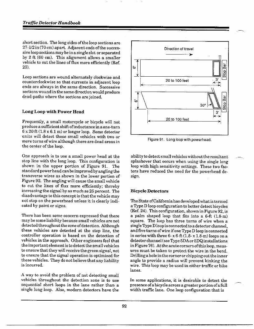
fiafic Detector Handbook
short section. The long sides of the loop sections are27.1/2 in (70 cm) apart. Adjacent ends of the succes-sive loop sections may be in a single slot or separatedby 2 ft (60 cm). This alignment allows a smallervehicle to cut the lines of flux more efficiently (Ref.23).
Loop sections are wound alternately clockwise andcounterclockwise so that currents in adjacent loopends are always in the same direction. Successivesections wound in the same direction would producedead-paths where the sections are joined.
Long Loop with Power Head
Frequently, a small motorcycle or bicycle will notproduce a sticient shift of inductance in a one-turn6 x 20 ft (1.8 x 6.1 m) or longer loop. Some detectorunits will detect these small vehicles with two ormore turns of tire although there are dead areas inthe center of the loop.
One approach is to use a small power head at thestop line with the long loop. This configuration isshown in the upper portion of Fignre 91. Thestandard power head can be improved by angling thetransverse wires as shown in the lower portion ofFigure 92. The angling will cause the small vehicleto cut the lines of flux more efficiently; therebyincreasing the signal by as much as 25 percent. Thedisadvantage to this concept is that the vehicle maynot stop on the powerhead ufless it is clearly indi-cated hy paint or si~s.
There has been some concern expressed that theremay be some liability because small vehicles are notdetected throughout the zone of detection. Athoughthese vehicles are detected at the stop line, thecontroller operation is based on the detection ofvehicles in the approach. Other engineers feel thatthe important element is to detect the small vehiclesto ensure that they will receive the green signal, notto ensure that the si~al operation is optimized forthese vehicles. They do not believe that any liabflityis incurred.
A way to avoid the problem of not detecting smallvehicles throughout the detection zone is to usesequential short loops in the lane rather than asingle long loop. Nso, modern detectors have the
~r%tion of travel
*11
~Q~20 to 100 feet
Lqi
< .
3
< 20 to 100 feet >
Hgure 91. Long loop with powerhead,
abflity to detect small vehicles without the resdtant .—splashover that occurs when using the single longloop with high sensitivity settings. These two fac-tors have reduced the need for the powerhead de-sign.
Bicycle Detictom
The Stite ofCdiforniahas developed what is temed
a &Pe D IOOPcOfi@ration to bettsr detect bicycles(Ref. 24). This confimration, shown in Fl~re 92, isa palm shaped loop that fits into a 6-ft (1.8-m)square. The loop has three turns of wire when asingle Type D loop is connected to a detector channel,and five turns of wire if one Type D loop is connectedin series with three 6-x 6-R (1.8-x 1,8-m) loops on adetector channel (see Type 5DAor5DQinstallationsin Fi@re 76). At the acute corners oftfis loop, meas-ures must be taken to protect the wire in the bend.Dfilingahole in the corner or chipping out the innerangle to provide a radius wfll prevent kinking thewire. This loop may be used in either trafic or bikelanes.
In some applications, it is desirable to detect the ,_presence of a bicycle across a geater portion of a fullwidth tr~lc lane. One loop confi~ration that is
92

Detector Design - Chapter 4
-
Diretiion of Travel
Winding Detail Sawcut Detail
Figure 92. Type D loop configuration
used is m 8-ft (2.4-m) square with three diagonalsaw cuts traversing the square. Two layers ofwire are used and are wound so that the currentflow is in the same direction for both layers.This results in four layers of wire in eachdiagonal. The acute mgle corners are rounded
‘n to prevent damage to the wires. This is a specialconfi~ration that is used in areas of hea~bicycle traffic such as near the University ofCalifornia at Davis.
Wind two successive layers,Each layer is as shown belowwith same diretiion of winding
Winding Sawcut
Figure 93. Wide coverage bicycle loop
One method of bicycle detection ia to place loopswithin the traveled area of a bike lane that wfll
~, reliably detect bicycles and provide an adjustabletimed call extension to hold the call to the controllerlong enough for the bicycle to clear the intersection
when operating in a Loop Occupancy mode. k
appropriate design that is essentially twoquadruples side by aide is shown in Fi@re 94.The 4 1/2- x 6-ft (1.4- x 1.8-m) confi~rationurovides assurance of detecting all bicycles andcomplete adjacent lane rejection.
Direction
of Travel ●
Curb tine
Kgure 94. Bicycle lane loop layout
DE~C~ON OF LONG, ~GH BEDWmcms
It is generally a good idea to allow long, high bedvehicles (e.g., tandem trucks, semi-trafler trucks,and cars pulling trailers) to travel through theintersection without stopping. There are three strongreasons why long vehicles should not be stopped.
. Jack-knifing of truck-trders tends tooccur under heavy braking conditions.
● ~er stopping, a large vehicle reqtiresa longer start-uptime delayingfollow-ing traffic.
. Inmeased noise and tir pollution areassociated with hea~ truck start-up.
93
.—

Trafic Detector Handbook
,-,.
One detection alternative for trucks consists of twoloops spaced 30 ft(9m) apart andlocated302ft (90.6m) from the stop line (Ref. 25). This is the distancethat would be required for a loaded semi-trafiertraveling45 mph (72 kph) to come to a safe stop. Thedetector logic requires that the second loop be acti-vated before the first loop is vacated.
One freeway pro~am (in Detroit) required that allvehicles be detected as a single entity, includinghigh-bed tmcks, semi-trafiers, and tanker trucks aswell as conventional vehicles. Their test of threeturn 6-x 6-fi (1.8-x 1.8-m) loops did not adequatelysatisfy their requirement. Afier numerous trials,the agency detemined that a seven turn 6- x 6-ft(1.8- x 1.8-m) loop rotated 45 de~ees to form a dia-mond shape was superior particdarly in their accu-racy in detecting trucks. The diamond shape wasfurther refined by carefully adjusting the angles ofthe diamond to avoid splashover (Ref. 25).
One manufacturer states that the ability to detecttrucks reliably due to confi~ration change is notdue to the diamond shape of the loop as suggestedabove. Rather it is due to the increased number ofturns which increases the inductance of the loop.The amount of signal received by the detector isdependent on the loop inductance to lead-in cableinductance ratio. Simply stated, when the loopinductance to lead-in cable inductance ratio is equalto one, then the amount of change seen by thedetector is U2 the change occurring in the loop. Byincreasing the loop inductance (by increasing thenumber of turns to seven), Detroit has ~eatly in-creased the amount of change received at the detec-tor, thereby, resdting in more reliable detection ofhigh bed tmcks.
Q~~DETEC~ON
Freeways that are operating under congested condi-tions are likely to periodically result in heavy vol-umes on off-ramps. men these off-ramps termi-nate at a signalized intersection, backups can ex-tind to the freeway lanes, causing even more conges-tion. Depending upon agency policy, it may bedesirable to detect and discharge such queues beforethey become a freeway problem.
One solution uses an actuated controller with aqueue discharge system consisting of a queue detec-
tor tith a bufit.in delay time (hf. 21). As shown inFi@re 95, the queue detector loop is located at astrategic position at the upstream end of the off-ramp. A timer statis when a vehicle enters thedetection zone of the queue detector and resets to Owhen the vehicle exits the zone of detection. If thesystem times a predetermined number of seconds,the detector’s nomal output relay is ener&ed.
If the queue ofvehicles waiting at the red indicationextends upstream to the queue detector, a vehiclewill be over the loop longer than the selected delaytime. men the delay timer times out, the detectorlogic issues a si~al to discharge the queue. TheWeen si~d will remain on until all vehicles aremoving with gaps longer than the loop itself.
The detiction loop must be long enough b span thedistance between standingvebicles. Concomitantly,it must be shotier than the shortest gap in movingtraffic so that the bre~s between motin~ vehicleswill cause the delay timer to reset. fiis latterconsideration can be critical when the queue detec-tor covers two or more lanes. A loop length of 30 ft —(9 m) wfil generally satisfy this criteria.
Sutiace Street, OA~~
i
offRampOB
Normal OBDetector
Hgure 95. Queue discharge system
.—
94

Detector Design - Chapter 4
P
DE~C~R DESIGN FOR ~CCONTROL SYS~MS
The detector requirements for area-wide trficcontrol systems are dependent on the type of controlto be implemented. ~me-of-day control does notreqtire detectotiation as it is basically a time-clockoperation. First generation traffic responsive cOn-trol and other advanced control strategies do requirea system of detectors capable of early identificationoftrfic trends within a system. It must protide anearly indication of a peak period for the beginning ofheavy traffic. Thus, the detectors must be placed onheavfly traveled lifis tith traffic patterns repre-sentative of the si~ificant flows within a section ofthe area-wide system.
The application of detectors in various forms oftraffic control systems was defined in Chapter 3.Detector design considerations fortrafficresponsivetrtilc control systems are discussed below.
r. Accwacy tials
Men designing a detector sumeillance system foruse in computerked trafic control systems, the useof the gathered data and measures to be collectedmust be considered. As discussed in Chapter 3,volume and occupancy can be measured effectively.The remsiningvariables are only ro~h approxima-tions of the actual conditions. In estimattig liuk-specflc volumes, three components oferror combineto limit the accuracy potential of each of tie controlvariables. These are:
.
.
.
A measurement error in the data onwhich the predictor operates.
A prediction emor in estimating theunderlying mean.
A component reflecting the random-ness of trtic.
The data emor can be expressed as X percent proba-blhty that the emor wodd be within Y percent. Anomd distribution is assmed for the mean value
,nof a large sample. The count error for First Genera-tion UTCS cfitical intersection control was plus orminus three vehicles 90 percent of the time (Ref. 26).
For determining measures of effectiveness, severalfaltering and smoothing techniques may be used. Afiltering equation is used which takes the old.smoothed value (like volume) and detemties thedifference between it and the latest unsoothedvalue. The dfierence is used to update the value ofthe smoothed data.
&other error is introduced for vehicle presencebecause the computsr is not obseming vehicle pres-ence continuously, but is sampling. ~ls resdts inan emor in occupcncy and speed computations. merewfll always be a sampling emor that increases asvehicle speed increases. This error cannot be elimi-nated, but can be decreased by inmeasing the sam-pling rate. Rf. 27 describes how to compute thepercent sampling rate as well asflteringand smooth-ing techniques.
Link Selection for CIC
me location of detectors in a traffic control systemis a three skp process. First, links are selected fordetectortiation. The lateral and longitudinal detec-tor placements are then determined. The Ed selec-tion must consider each function in the sequence,beginfing with intersections which are candidatesfor Critical Intersection Control (CIC). Candidateintersections are those that could teke advantage ofvariable split, but which operate in an unsaturatedcondition. men detectorizing an intersection tooperate under CIC, dl approaches sewed by phaseswith variable geen times must be detectorized. Thestep-by-step process for determining CIC candi-dates is given in Ref. 28.
The need for measuring general traffic trends wfllprobably be satisfied by the CIC detectors in area-wide sumeillance systems. If this type of detectori-zation has not been installed, detectors should belocated on major collectors or distributors to thenetwork to obtain system trends with a mitimum ofinstmmentation. Another WOUp of candidates forthis tvBe of detectirkation are entrances and efits.“..
of large parking facilities that would have a si~Wl-cant effect on local trafic conditions.
Tke location of detectors to evaluate system opera-tion is, to a large extent, dependent upon the de~eeof accuracy required by the evaluation. If a general
95

Wafic Detector Handbook
—
evaluation of changes in system operations is de.sired, the detector placement for tr=lc responsiveoperation would be adequate. If a more detifledevaluation is required such that speed and delayscan be determined, it will be necessary to increasethe number of detectors within the system. me costof this de~ee of detectorization may suggest thatother techniques be employed.
Lane Selection
It has been demonstrated that a single detector inthe lane carrying thematimum through volume wfllbe the most representative of the trtilc to which thesi~al must respond. Moreover, the signal should betimed for critical lane volumes. However, it is notpossible to derive reliable total volumes from asingle detector. Yet, multiple loop detectors locatedin noncritical lanes may introduce emors that ex-ceed the value of the data they provide as they aremeasuring parking vehicles, turning vehicles, etc.(unless individual lane detections used). ~us, themost reliable data is detived from the critical lane.me critical lane (defined as the one carrying thefleatest volume) is usually easy h identify by ob-serving the length of queues at the intersection.
At locations where the critical lane changes withtime of day, mtitiple lanes should be detectortiedand the time of day factors used in the software toselect the detector cumently measuring tme criticallane volumes.
Field measurements shodd be made of the trtilcvolumes on each lane of an approach (Ref. 5). Aver-age lane volumes per cycle are computed and com-pared with the tentative critical lane. mere are fourconditions that will require engineering jud~ent,including project priorities and a knowledge of indi-vidud link trafic. ~ese conditions include:
● Approaches where one lane is alwayscritical.
● Approaches where the critical laneshifts between two lanes, but thedifference in volume is not geat or theshift is infrequent.
● Approaches where shifts in criticallanes are significant.
● Approaches exhibiting specfic criticallanes during penk hours, but, for vari-ous reasons, erratic, shifts in criticallanes occur during non-peak periods,
It is unusual for more than two lanes to reqtiredetectorization and most often only one lane willneed a detector. ~er the critical lanes have beenidentified for the links to be detectorized, it is neces-sa~ to determine the longitudinal placement of thedetectors on the links.
Lon~tudinal Plamment
mere are two guidelines for the longitudinal place-ment of detectors for signal system control. Onerelates to the upstream intersection and the secondrefers to the downstream intersection. From theupstream intersection, a detector should be down-stream from the zone of acceleration of vehiclesentering the link. A distance of approximately 230ft (69 m) is recommended.
From the downstream intersection, the detectorshould be upstream from the point beyond whichstanding queues of vehicles do not usually extend.Mthough this distance is a function of the cyclelength, split, and offset, it is recommended thatvalues of200 to 250 ft (60 b 75 m) be used in urban@d areas and values of 300 to 350 R (90 to 105 m)be used in suburban atierid systems. men bothcriteria cannot be met, the criteria based on typicalqueue size is considered the more critical.
One additional longitudinal detector placement is-sue is in the location with respect to trafic sinks andsources (e.g., parking facilities). Detector placementresearch has shown that a sintisource has a mini-mal effect on trfilc measured in the critical lanewhen the facility is operated as a sink such as aparking garage during the morning peak. ~rnsinto the garage are made from the curb lane whichis not usually the critical lane.
Ody during the evening peak hour when the garageis functioning as a source are there measurableeffects on the critical lane. An evaluation of thepaths of vehicles entering the lane from a sourceshowed that most vehicles wait for a su~cient gap to —enter the specific lane within the link. It is sug-gested that a cfitical lane detector be located at least
96

Detector Design - Chapter 4
50 ft (15 m) downstream from the source, providedthat the downstream intersection criteria is notviolated. Ingeneral, unless the source contributesmore than 40 vehicles per hour to the critical lane,the effect of a source on the link demand is notsignificant.
System Detectir hcation Summav
The ifiomation developed in earlier tasks dl re-sult in the selection of links to be detectotied, thelanes in which the detector should be placed, and anapproximate location with respect to the upstreamanddownstream intersections. With this infoma-tion shown on a map, afield visit should be con-ducted for each EA.
A “walk througW by the desi~er till permit theselection of find locations considering access to thecontrol equipment, special driveway problems, orother roadway orparkingconditions. Eachlocationmust pass a reasonableness test as well as theanalytical test.
Several general ~idelineshave been suggested con-cerning the field location ofindividual loop detectirs(Ref. 28):
.
.
.
.
A detector should be located in thecenter of the traffic flow, not necessar-ily in the center of the marked lane.The center of the traffic flow can usu-ally be ident~led by the oil markingsor tire tracks on the pavement.
The detector should be located in theareas ofstabletrtilcflow. Sectionsofa link with excessive weating or heav-fiy impacted by entering and exitingdriveways should be avoided.
Where a major driveway is locatedwithin alink, the detector should belocated at least 50 ft (15 m) down-stream from the driveway protidedthe detector is at least 200 ft (60 m)upstream of the stop line.
Mafflc detectors should not be locatedwithin 10 ft (3 m) of any manhole,
water valve, or other appurtenancelocated within the roadway. Thisdistince is required h permit stil-cient clearance for work on the man-hole without disturbing the detector.
In summary, the final decision concerting the loca-tion of detectors for advanced traffic control strate-gies is a blend of analytical procedures coupled withengineering jud~ent. It must be reco~tied thatnot dl li~s can be instmmented to yield inputmeasures tithin the accuracy required by the alg-orithms. Short links, and links tith extremely poorlane discipline are typical of those that are not com-patible tith accurate instrumentation.
LOOP DETECTOR ELECTRONICmT
The operational characteristics of the various typesofdetector electronic units beingmanufatiured todayare discussed in detafl in Chapter 2. Requirementsfor loop detector electronic devices are included inboth the NEW Standards and the Type 170 Speci-fications (see Appendices I and J). The NEMAStandards define a series of self-contiined loopdetector units desi~ed for shelf mounting. It alsodescribes a card-type detector ufit desi~ed to in-sert into a multi-card detector housing rack. Theretised NEMA Stindards (TS-2) are expected hemphastie card-rack mounted units. The ~pe 170Specifications define card-type detictirmoddesonly,that are desi~ed for insertion into the input file ofthe cabinet system.
The NEW detector units are available with eitherone, two, or four independent detector channels peruuit. Some agencies insist on using only singlechannel detector units because they believe thatfailures in the unit can be more easfly correctid byreplacing a single unit rather than having to replacea multiple channel ufit for a single channel faflure.Cument reliability of detector units makes thisar~ment obsolete. me rack-mounted modules usedin the Type 170 system contain either two or fourindependent channels.
The NEMA Stindards dso define optional timingfeatures, dloting for the delaying or the extension
97

Traflc Detector Handhok
of the detector output. In the delayed cdl mode, thedetector wfil wait a user-defined period afier a ve-hicle enters the detection area, before it sbtis theoutput signal. In the extended cdl mode, the detec-tor will extend the output after the vehicle leaves thedetection area. The be 170 detector does notprovide this capability as it is normally petiormedby software in the controller uuit itself.
WG~TO~TERCO~IGWTIONS
The magnetometer detector system consists of oneor more maWetometer sensors (probes), the magne-tometer detector unit, and the lead-in cable betweenthe sensor and the detector unit. A typical magne-tometer installation was shown earlier in FiWre 36.The probe sensor instilationis shown in Fignre 96.
As described in Chapter 2, the magnetometer is apassive detice. There is no radiatid field or cone ofdetection. Theprobe-type sensor detects a change inthe vetiicd component of the Earth’s magnetic fieldcaused by the uassaze or uresence of a vehicle. The-.magnetometers, like the inductive loop detector, canbe used for either passage or presence detection.
Dtill hole withdameter equal tothat of sensingelement + 118.Depth asrecommendedby manufacturer.
Epoxy filla ,
Cover with dsk
Caulk to prevent Pavement
Magnetometersensing element. Treated baseInstall level.
figure 96. Typical magnetometer probe installation.
—
Because the probes are buried in a drflled hole
approximately 18 in (0.5 m) below the sutiace, theyare pfimafly used in the notiheasternUtited Stateswhere the pavement deteriorates more rapidly duek themal expansion and contraction and suffersdamage from snow-removal equipment. They aredso used in areas where loops cannot be cut in theroad sufiace, such as on steel bridge decks.
The configuration for a magnetometer installationis dependent on a number of factirs that must beconsidered. In desi~ngthe optimum configurationfor a spec~lc location, it is necessary to detirminethe best tradeoff between these factors. The follow-ing section discusses these factirs and their impacton the ultimate configuration.
Magnetometers wfil detect a vehicle whenever asufficiently intense portion of its magnetic shadowfalls on a probe. The dimensions of a vehicle’sma~etic shadow generally approximates the gee- .—metric dimension of the vehicle. In some cases, thema~etic shadow maybe offset by a few feet in anydirection.
Detection units for the ma~etometers typicallyprotide two independent detection channels. Eachchannel may have up to 6 probes connected to itsinput device. If only one probe per channel isinstalled in the street, the entire channel sensitivityis avafiable to that single probe. However, as thenumber of probes per channel is increased, thesensitivity is divided among the probes, thus de-creasing the sensitivity of each separate probe. Forexample, when four probes are connected to a singlechannel, the total channel sensitivity remains thesame, but the sensitivity at each probe wfll bereduced to one-foutih of the channel sensitivity.
It is therefore necessary to detemine what type ofvehicles are to be detected in order to select theproper spacing between probes and to define howmany probes might be tied in together per channel. ,_The number of probes reqtired per lane and theiroptimum cross-lane position is determined by the
98
—-

P
,n.
,-.
Detector Design - Chapter 4
lane width and the size of the vehicles to be detected.As a general rule, some potiion of the vehicle mustpass over a probe to be detected. Some general@delines for the number of probes for a given typeof vehicle and the number of probes per channel aregiven below.
. Auto, Tmcks, md Buses: Installprobes at5ft(l.5m) intemds. Skprobes per channel maximum.
● Motorcycles (300 ccandl=ger):Install probes at4- ft(l.2-m) inter-vals. Four probes perchannelmafi-mum.
. Motor Bikes (70-300 cc): Installprobes at 3-ft (0.9-m) intervals. Threeprobes per channel mafimum.
. Bicycles Install probes at3-ft(O.9-m)intemals. ~oorthree probes perchannel.
The ma~etometer detection system till operateproperly at latitudes north and south of the narrowequatorial band. Sites should be chosen to avoidconditions that would adversely tiect operation,such as: adjacent to manholes or large pipe% nearve~ Mgh current transmission lines, trolley lines,orundergmund power lines; or within tunnels orother enclosing iron stmctures.
Magnetometers are frequently the detector of choiceon bridge decks. Fi@re 97 Olustrates a typicalbridge deckinstdlation. Thepresence of the steeldeck over orunderthe probe has little effect onsystem pefiormance. However, vertical structuralsteel members may detract from petiomance byreducing the intensity of the adjacent ambientma~eticfield. Aswithloops, themostappropriatelocation for the probes is at the maximum distancefrom the steel supports or columns as shown in theillustration.
AmaWetic field analyzer should be used to measurethe intensity of the magnetic environment at theselected location. This instrument measures gee-magnetic field intensity, magnetic noise, and a.c.ma~etic field strength. It is especially useful atlocations where the use of magnetometers is ques-
k
.agnetichness
Hgure 97. Typical bridge deckinstallatiOn.
tionable (e.g. within tunnels, near large electricaldevices, etc). Atypical maWetic field analyzersshown in Fi@re 98.
There are some situations where manmade mag-netic noise is of stilcient intensity to impair per-formance of thema~etometer. These situations
figure 98. Magnetic field analyzer.
99
Tra@c Detector Handbok—
occur at sites where non-vehicular induced mag-netic field changes exceed 5.0 millioersted. Mag-netic field changes of this magnitude are almostalways man-made, such as street car lines, sometrolley bus lines, subway trains, or nearby elevators.However, few sources are of sfilcient intensity toaffect a detectir probe located more than 30 ft (9 m)from the source.
PROBE PLACE~NT
The optimum lateral placement ofprobes in a lane isdetermined by such factors as the width of thenarrowest vehicle to be detected, the lane width, andthe detection quality required. Some pati of thema~etlc shadow of the vehicle must fdl on one ormore of the probes for detection to ocmr. Conse-quently, the maximum probe spacing is equal to thewidth of the narrowest vehicle to be detected. Sincemost autos, trucks, and buses are tider than 5 ft(l.5m), a single probe centered in a 10-ft (3-m) lane wouldgenerally protide adequate pefiormance. In a 12-R(3.7-m) lane, a single probe may fail to detect someof the small vehicles traveling near the edge of thelane.
By increasing the number of probes to two per lane,virtually dl four-wheeled vehicles within a 12-ft(3.7-m) lane would be detected. In this type of con-figuration, probes should be placed no further than5 ft (1.5 m) from each lane boundary. Furthermore,if bicycles are to be detected, more probes per lanemay be needed.
In general, the quality of detection improves as thenumber ofprobes per lane is increased because of thespecial averaging which resdts when the magneticshadow of a vehicle falls on several probes judi-ciously spaced. Reduction in field intensity at onelateral position maybe compensated for by increasesat other positions.
PROBE DEPTH
Vertical placement of probes is an impotiant deter-minant of system pefiormance properties. Deepplacement such as 18 in (45 cm) to 24 in (80 cm)provides good single count vehicle presence detec-tion, but results in a lower siWd level. Conversely,shallow placement, say 6 in (15 cm), provides higher
signal levels, but tith an increased incidence ofmd.tiple counts per vehicle. Mdtiple counts tith shd-IOWplacement resdt primarfiy from the passage ofmajor components of the vehicle such as engine,transmission, and differential, each of which mayproduce a separate magnetic petiurbation. By in-creasing the depth to 18 to 24 in (45 to 60 cm), mostvehicles yield a single perturbation of the magneticfield as the deeply butied probes sense the overallma~etic bdk of the vehicle rather than details ofthe understmcture.
In summary, for detection application where onlypassage infowation is required and where multiplecounts are not detrimental, probes should be locatednear the sutiace. Similarly, in constant speed appli-cations where the time extension feature of theexpendable presence mode can be used effectively,probes may be located near the sutiace. Small two-wheeled vehicles such as bicycles or motorbikesdevelop narrow, low intensity shadows. Their detec-tion also requires shallow place of probes.
—
SUGGES~D CO~IGURA~ONS
There are a number of confi~rations of probe place-ments. Some typical designs are presented in Ap-pendti L. These examples illustrate the varioustradeoffs that are available with probe depth andlateral distances between the probes. The examplesinclude confi~ations for single lane, two, and threelane detection, wide lane detection, and detection fortwo-wheeled vehicles. Mso shown are some sug-gested confi~rations for left turn lanes with zonesof detection ranging from 30 b 70 ft (9 to 21 m).Fi@re 99 depicts detector confi~rations for variousmodes of operation.
_ SI~ AND CAB~ SE~CTION
Minimum wire sue is determined by the cable lengthand the number of probes per channel. The probeexcitation circuit provides cument at a constant 125milliamperes peak-to-peak, but is limited to a 15 voltpeak-to-peak sting (see Chapter 2). Maximumallowable probe-cable assembly resistance is there-fore 125 ohms. At resistance levels below this limit, _system operation is normal. At higher resistancelevels, instabfiityand peflormance de~adation wflloccur.
100

Detector Design - Ckpter 4
*
Effective resistance of each probe is approximately4 ohms. Robes on the channel are connected insefies electronically so their resistance is additive.Mlowable cable resistance is 120 ohms less the sumof the probe resistmces. AWG#22 copper wire ptirshave a loop resistance (going and returting total) of35 ohms per l,000ft(300m), AWG#20pairshave 20ohms, and AWG #18 pairs have 13 ohms. Because ofthe changes in wire resistance with temperature, itis recommended that #18 AWG wire be used on cablemns exceeding 2,000 ft (600 m) in cfimates whereextreme temperature ranges are typical.
Interconnection of tie magnetometer detechr andprobes reqtires two pair of conductors per channel.One pair supplies the probe excitation current andthe other camies the return signal. Properties of thecable become especially sigticant in long transmis-
Mode
Presence
Call/Pass~ g
d d d d
Multiple lanes toone channel
Soeed/Occuoancy
M
One channel per lane
Classification(speed/length)
w
Two channels perlane
3perati0ri
Pulse
w
d d d z =
One channel per lane
Swee d measurement
m
TWO channels per lane
Laroe area wresence
TWOchannels per laneAlternate sets of probes(2,4, or 6 probes perchannel)
figure 99. Magnetometer probe placement.
sion distances of over 2,000 ft (600 m). me cablesshould combine distance capability with high noiseimmutity and environmental tolerance.
As discussed earlier, up to 12 probes per channel canbe used. However, as the number of probes in-creases, the allowable lead-in length decreases.Generally, the lead-in length shodd not exceed4,000 ft (1,200 m) for a 12 probe per channel insta-llation. If, on the other hand, 6 probes per channelare used, the lead-in length should not exceed 5,000ft (1,500 m).
WG~TIC DETECTORCO~IGWTION
Nthough the magnetic detector was developed inthe 193Us, it is stfll in use today patiicdarly wheredeteriorated pavement antior frost actitity tend tocontribute h the faflure of loop detector wires. It isdso used where it is desirable to install detectionwithout cutting the pavement. Whfle this form ofdetection is inexpensive, reliable, and simple, it issuitable only for pulse output in traffic actuatedsiWd control and trafic volume counting.
As described in Chapter 2, the ma~etic detectoroperates on the basis of a change in the lines of fluxfrom the Eatih’s ma~etic field. Atypical ma~eticdetectir probe is shown in Fi@re 100. A cofi of wirewith a highly permeable core is placed below thesufiace of a roadway. men a metallic object such asa vehicle comes near or passes over the cofl, the con-stant lines of flw passing through the cofl aredeflected by the vehicle, thus inducing a voltage in
;:.e.,,~.. . . . . .~.. ,<..c,.
,.
.,.. : :
t.:.:.””?: “.”.’ ;
Rgure 100. Typical magnetic probe.
101

~a~c Detector Handbook.—
the coil. A high-gain amplifier then enables thisvoltage to operate a relay which sends a message tothe controller that a vehicle has been detected.
The following discussion is limited to the non-com-pensating form of magnetic detectors. The non-compensating detector is a tube approximately 2 in(5 cm) in diameter and 20 in (50 cm) long placedbelow the sutiace of the pavement.
~G~~C DE~CTOR PROBEPMCE~~
The placement of the probe is patiicularly impor-tant to the proper operation of this detector system.Since the probe detects changes in the ma~eticfield, a vehicle must be meting at a speed ~eaterthat 5 mph (8 kph). This means that it must beplaced far enough back from the stop fine wherevehicles are normally in motion (generally at least50 ft (15 m)). It must dso be placed in the most
apprOpfiate location in the lane to generate a sufi.ciently strong impulse to register a detection.
Distance fmm the Stop Line
The set-back distance of the probe from the stop lineis based on the desirable allowable gap. For ex-ample, assume an allowable gap (therefore passagetime) of 3 seconds. Then, on a street with anobsemed speed of30 mph (48 kph), the probe wouldbe located 182 ft (55 m) from the stop line.
The graphs shown in Fi@re 101 identifies the properlocation of the probe relative to the stop line based onan allowable gap of 2, 3, 4, or 5 seconds.
Lateral Placement of Probe
In a single lane approach, the optimal location isunder the path nomdly followed by the right wheelsof the vehicle as shown in Fignre 102. On a two lane
apprOach where a single prObe !S used, the probeshould be placed between the lanes to protide satisf-actory coverage. If the right lane of a multi-lane
apprOach is designated for right turning trafic, theprobe should be located in the middle of the throughlane to minimize the effect of vehicles in the rightturn lane.
400
350
300
250
200
150
100
50
,. ,, -
~
Allowable Gap ;--- 2 Sswnds : ;/O
—-- 3Semnds
_ : ::::j: ..i.*z *’x *..
,: 4 .*i,! . .. .. .
/ - !/ ~~
.+..:.. .. .. .. .. ..
‘-10 20 30 40 50 60
Obssrvsd S~ed, mph
figure 101. Proper location of magnetic probe,
A common practice for multi-lane approaches, is to ‘—place a probe in each lane. In such desi~s, the probeshould be placed under the right wheel track in eachlane. Up to three probes can be placed in a conduit,men the ma~etic probes are to be placed in a newroadway, mdtiple conduits should be used, oneprobe per conduit. In an existing road, conduit rnnsshould be kept to a minimum; thus more than oneprobe may be placed in a .condtit.
102

Detector Design - Chapter 4
When two or more probes are used on differentapproaches of the same traffic phase, they should beplaced in similar locations (if possible) so the dis-tance each probe till have to cover will be the same.~is will allow for the sensitivity of all detectors hbe adjusted by the single sensitivity adjusting knobon the detictor unit.
me probe sensor till generate an impulse in re-sponse to any change in the magnetic conditionssumounding it. me strength of the impulse is
proportional b the change in the magnetic field.Changes in the ma~etic field can be caused bymovement ofiron or steel objects in the ticinity or bychanges of current in power tires. With the probeplaced as close as possible to the path of the vehicles,the stren@h of the impulses caused by these veM-cles till be maximized. Impulses caused by traficmoving in other lanes or by current changes innearby tire will be minimtied. me sensitivity ofthe detector, can be turned down until the unwantedimpulses are not strong enough to actuate the relay,while the impulses from vehicles in the proper laneswill be strong enough b actuate.
103
—

m.
5. INSTMMTION
Installation may be considered by some as the sim-plest, most straightforward activity in the process ofimplementing detection capabilities. men detectortheory and application have been reviewed and thedesi~, spec~lcations, and plans have been devel-oped, iastdlationmay appear relatively easy. hongdl the complicated en@eefing activities alreadyundetiaken, surely the mechanical task of cutflng aslot in the pavement, laytig turns of wire in the slot,covering it tith sealant, spliciW it to the cable, andconnecting the cable to the electronic rmit in thecontroller cabinet wordd not seem to present a difi-cdt challenge.
In reality, this seemingly uncomplicated actitity isthe most cmcial process in the chain of events.Improper or “sloppy” installation causes many of thedetector faflures and signal malfunctions. There is
,- no more impotiant actitity in the system to ensureeffective operation.
For example, consider that the detection elementrepresents about 4 to 10 percent of the cost ofimple-mentingintersection traffic control, yet accounts fora si~~lcant potiion of maintenance dollars. More-over, as trafic congestion and delay become a moreurgent problem, and trafic control equipment be.comes more sophisticated to better manage thistraffic, dependence on properly functioning detec-tors becomes more important.
This chapter is specifically addressed to project en-gineers, contractors, inspectors, field crew supemi-sors, and traffic technicians. It begins with a discus-sion of pre-installation activities, regardless of thetype of detector selected. To underscore the critica-lity of the installation process, the magnitude andcauses of loop detector failure are then addressed.
The various activities comprising the process ofinstalling loop detectirs in existing roadways arethen described, followed by a dismssimr of loopinstallation in new roadways or as part of a repaving
firocess. Installation of ma~etometers and mag-letic detecbrs is discussed later in the chapter.
me design of the detetior systim (see Chapter 4)involves a number of decisions that must be madepretious to installation. These decisions includespecifications for the type and configaratimr of thedetector hardware necessary to meet preciouslyidentified operational requirements, and a prelimi.nary plan of the location.
We-installation activities should include a thoroughreview of the desigrr documents, preparation of scaledrawings, and field tisits h the location. Uponcompletion of these activities, the engineer is readyto hand the job over to the instrdlation crew foremanor the contractor who must then develop manpowerestimates, and material and eqnipment require-ments. Ml itiofiatimr shodd be clearly definedand complete so that instdlatiorr can proceed in anorderly manner.
A scale drating of the location showing the correctgeometry of the roadway and the exact location ofthe in-road sensor element in relation to the pave-ment markings shodd be prepared. The drawingshodd dso show the location and content ofcondnit,ma~oles, power sources, pavement materials, andelectrical equipment that wodd intetiace tith theinstallation. The accuracy of this drating is of~eatimpotiance ta effective installation as it wfll becomethe basic @deIine for the instigation crew as wellas a part of the procurement package if the instiga-tion is to be petiomed by a contractor.
The completed drawing should be retiewed with thedesi~ en~neer ta insure that the loops (or probes)are located as specified in the confi~ration designand in areas free ofunder~ound or wderpavementhardware that could intetiere tith proper opera-tions.
105

~a@c Detector Handbook
.—
F~~ WSITS
Field visits to the site of the installation should bemade before and after the scale construction draw-ing is made. Prior h preparing the drawing, afieldvisit shodd be made to inventory the efisting condi-tions and to identtiy any pokntid problem areassuch as pavement joints, which may tiect loopdesifl.
As a result of this visit, the project engineer shouldthen determine the method for burying cables andthe types of equipment needed for the installationstrategy. The method of traffic routing and controlduring installation should also be determined in-cluding the position and quantity of bamicades orcones that may be needed for trtilc control. Finally,the pemits and licenses reqtired for installationshould be identfied.
Thetiformation obtained fromtheititialvisit shoddbe incorporated into the plan drawings. ~er thedrawings are completed, a second field visit shouldbe made to verify their accuracy.
If the installation is to be preformed by an in-house(force account) crew, the next step would he toestimate manpower requirements. The plans tillprovide sufficient information to determtie the scopeof the installation work, the amount of time re-quired, and the stie of the crew necessary to pefiormthe installation. Depending upon the size of thecrew, many of the tasks can be peflormed simdtane-ously to reduce the total time that traffic would bedisrupted.
It is also necessary to detemine the eqtipmentrequired for the instillation. The type and confi@-ration of the detector system will, in effect, dictatithe equipment necessary for installation. Table 18lists the commonly used equipment for a normalinstallation of loop detectors. Barricades, signs,cones, safety vests, and other devices till dso be re-quired to control traffic safely during the installa-tion procedure.
Table 18. Equipment for typical loop installation.
Item
Power Saw
Water Supply
Jackhammer
Ar Compressor
Chisel & Hamm6
Blunt TOOI
Twister
Template/Straight Edge
Trenching
Megohmeter &VolUOhm Meter
Loop Analyzer
Soldering Iron
Measuflng Tape
DesctiDtiOn ISelf-propelled 18-65 hp saw equip~dwith 1/4 to 318 in (6.4 to 9.5 mm) tti~blade (abrasive or diamond), watervalve, depth gauge, and horizontalguide
For use with diamond blade to COOIblade and clean out saw slots IFor bring holes through ancretecurb IFor use with jackhammer and to cleanand d~ sawed slots
For removal of sharp edges at cornersof saw cuts
Such as a wooden stirting stick forseatina wire in saw slot I
TO provide symmetrical twists of theIead<n wires
For marking outlines of loops onpavement
For burying cable in difl
—.
For inspecting and testing wirecontinuity and resistance I
TO test continuity and indutiance of Ithe loop .
Either a butane torch with a solderingtip or an electric soldeting iron forsolder connetiions
Minimum 100-ft (33-m) tape for exactmeasurements for placement of loops
In addition to the equipment listed in Table 18, theinstallation of maWetometers requires a drfll andblt to bore tie vertical hole in the roadway for theprobe. Additional equipment required for installingmagnetic detectors includes: a backhoe, ahorizontdboring machine, a level, and a tamping, machine.
m~~~Qm~NTS
As with manpower and equipment, the type andamount of material that will be needed should bedetermined. Care shoddbe exercised to assure that -dl materials are protided in ample quantities to
106

Detector Zmtallation - Chapter5
-
avoid any intemuptions of work on the street due black ofmatetils. Atypical materialist for loopinstallations is provided in Table 19.
LOOP DETECTOR ~ST&MTION
The loop detector system is composed of a tireloop(s) embedded in the pavement (the sensor), asplice between the lead-in tire and the lead-in cablein the pull box, the lead-in cable (usually in a con-duit) mnning to the terminal sttip in the controllercabinet, a cable from the terminal strip to the elec-tronic detectir unit, and finally, the detector unititself. The relationship of these vatious componentsis illustrated in Fi~re 103.
This section wfll initially present an ovemiew ofinstallation techniques. Loop failures as they relateto installation till then be discussed. Finally, con-ventional loop installations in etisting roadwayswill be addressed in terns of the most commonlyused techniques and materials. Unique installa-
_,,tions are discussed later in this chapter.
Table 19. Typical required matedals.
Item Usage
DetetiOrWre ~TO fOrmthelOOpa”dthe lead-in wies~
TO conneti the detector lead-in wireLead-In Cable in the pull box to the eletimnic unit in
the wntroller cabnet
To house and provide access to thePull Boxes connetiion (splice) between the
lead-in wire and the lead-i” cable
Sealant TO seal saw cuts
Cament, Sand, To dust on saw cut after sealant hasor Talc baen emplaced to prevent trating
[ Concrate ,I Forsattingp”ll boxas
Surge Voltage If necassa~, to provide protectionPrOteaOr in tha controller catinet
Solder ~ Formatingsplicas
spice Kts (orequivalent) For environmentally saaling splicas
Spray Paint orChalk and Line For otilining loop for sawcutting
Loop Detector Amplifier /
Green Chassis Ground I
i
RedLoop Input I
Oranae
I
I
@Controller ,’
Catinat /‘
@
@/
/
@
s
sBuried Nre Loop
@
Ground
_ Rod
●
Shiald Drain Wra
Figure 103, Loop system schematic
107

fia~c Detector Handbook
--
Loop detectors are installed in pavement, eitherasphalt or concrete, by cutting a slot, cleating anddrying the slot, laying in the detector wire, sealingthe sawcut, connecting the wire to the lead-in cable,connecting the cable to the terminal strip in thecabinet, and ensuring that the harness connects theterminal strip to the electronic unit. me major fieldsteps in this process are shown in Fignre 104. Dif-ferences in installation techniques usually involvethe treatment of the corners where two saw cutsintersect, splicing techniques, the type of sealant,
and the method of applying the particular sealant.Even tith Wls relatively simple installation proc-ess, there are many dfierent techniques used.
Installation techniques and theofies vary widelyamong trfic agencies. For example, a sumey ofwestern states (Ref. 29) provided the variationsshown in Table 20. Procedures developed over theyears me frequently out-of-date or are no longereffective, yet there is of in~eat resistance to change.In many cases, the installation of detectors is per-formed by contractors who have fieir own shortiuts(and shoticomings). me importance of appropriate
Table 20. Installation practices in western States.
I Alaska
Cahfornia
\ Idaho
!Montana
Nevada
IOregon
Utah
Washington
NOTE:
Type of LOOP Saw Cut CleaningDimensions Method
6 x 6 ft square (3 turns)6 x 20 ft (2 turns) — —
16 x 6 ff square or diamond w= 1/4- 1/2 Flush W/
(3 turns) inch water and6 x 6-50 ff Quadruple D=l 3/4inc blow outan(
(2-4-2 or 1-2-1 ) dy w/air
W = 318 inch6 x 6 ft square (2 turns) D=l l/2incl 1 Blow out
(minimum) WI air
Asphalt6 x 6 ft square W = 1/4 inch Blow out
6 x 20 ft quadruple D = 2 inch WI air(vatious # of turns) hncrete
W = 1/4 inch\D=l l/4i”c~
aD=2inch ‘::”
6x25 ftrectangle (2turns) W=l/4inch
Single loop - Flush W/4 x 4 fi diamond W = 1/4 inch water and
ries of loops D=l inch blow outSel3 x 3 ft diamonds WI air
(both 4 turns)
6x6 ftsquarafQ+, f,.=\ I I
6x16 ft recta! .. . . . . . . . . .
6;;i~~;ifi!”s) l;::*. I “air6 x 50 ff Quadruple D
(2-4-2) ‘inch I wair
r - ,,-,, ,”,,
=21Zt04 BIOWOM
states sphce loop lead-in wire to lead-cable in the pull M1
.ead-in cable runs to the controller are in conduit.
LoopMre
# 14 THNNStranded
! 12 RHW-USI(N:~f~ or
polyethylenestranded
Model 20002tehicle home-run cable (4 #8 condutiors),
7
#12xHHNstranded
t 12 RHW andXHHW
N, Nev - solidS. Nevstranded
#14 THWNstranded
# 14 THHN orTHNN
stranded
# 14 XLP,RHH, or RHWor#12XLP
stranded
Lead-InCable
IMSA 50-2 or # 1:twisted pair w/shield & drain
2 # 12 solidunshielded
2#140r#16stranded, shielde
4 # 18 stranded,shielded
Belden 8227
Belden 8720
IMSA 19-2 (Paircommunicationcable WI shield)
IMSA 50-2,Belden 8720, or
equivalent
Belden 8720, orequivalent
AIW 7311 orBelden 8716
1 in=2.54cm 1
DetectorMounting
Shelf
Rack
Rack
Shelf
MostlyShelf
Rack
Shelf
Shelf andRack
= 0.3 mDateof Survey: January, 1964 ,
—.
-.
108

P
f
Fgure 104. Typical loop installation details
—
109

Tra@c Detector Handbook
—
installation procedures in the long tem operationaleffectiveness of detectors cannot be overstressed.Given that loop detectors are primarfiyinstiled bycontractors, it follows that construction supervisionand inspection by the responsible agency is a cfiticalfactor.
Recently, detector instaRations have become evenmore varied. Because of the high failure ratesattributed h moisture or breaks in wire, the trend isto encase and seal the loop tires in some type ofprotective covering prior to sedingthe sawcut. Someagencies choose to pretind and bundle the loops inthe shop to ensure the proper number of turns andto save on-street time. Other agencies use pre-formed loops (i.e., the loop consists of V2- or 3/4-in(12- or 19-mm) PVC pipe with the wire enclosed).These loops require at least a l-in (25-mm) wide slotin the pavement rather than the narrow saw cutused for conventional loops. Some agencies haveused wider slots (up to 4 in (100 mm)) to facfiitatiplacement of the prefomed loop.
Because of their relatively harsh weather, Maskauses a ve~ protective Wade of preformed loop en-closed in l-in (25-mm) PVC pipe. They use Schedule80 (instead of Schedule 40) PVC pipe with a #12AWG crosslinked polyethylene tire with backer rodfill to prevent damage caused by water encroach-ment followed by freezing.
In addition, a West many detectors are now beingset in place during construction of a new roadway orduring repaving. In Puerto Rico, concrete slabs withthe detector loops in place are being used (see discus-sion later in this chapter under Loop InstallationMternatives). In this case, instead of a sawcut tohouse the loop wires, a section ofroadwayisremovedand replaced with a slab already containing the loop.The slab concept can also be used with new roadconstruction.
DE~CTORF_~S
The number ofloop detector failures nationwide hascreated deep concern in the trfic engineeringcommunity and an aggressive effort has been under-taken to determine the major causes of these fail-ures so that they may be eliminated or minimtied.During the 1980’s, FWA, in cooperation with vari-ous State agencies, funded a number of studies of
detector fdmes. The objectives of these studieswere ta quantify the scope of detector fadures, toidentify the causes of failure, and ti evaluate thevarious installation procedures (e.g. sawcutting andcleaning slots) and materials (e.g. sealant, conduits,wires and cables). The results of tiese studies arebriefly discussed below and arepresentedinAppen-dti M.
Causes of Detector Ftilure
In loop detectors, the failure of the detector systemcan likely be traced to the in-road detector sensor(loop wire) or to the splice between the loop wirelead-in with the lead-in cable. Since the introduc-tion of the digital self-tuning electronic units, fail-ure attributed to the amplifier/oscillator unit has allbut disappeared. Faflures continue to plague agen-cies stfil using the older utits that are unable toadjust to changes in temperature, moisture, orchanges within the loop and lead-in.
Loop failure literature is difflctit to synthesize be- ,_cause of the different terminology used to definefailures. For example, one report may categortie afailure as “break in loop wire.” ~ls maybe causedby crumbling pavements, fafiure of the sealant, aforei~ substance in the slot, or any number of otherreasons. A report from another agency may reportthis fafiure as “deteriorated pavement.”
No matterhowfaflures are categorized, the inescap-able conclusion is that the predominant causes forfailures in the loop detector system can be amelio-rated by improved installation techniques and vig-flant supervision and inspection.
Frequenq of F&lures
Considering the number of variables that may con-tribute @ loop detector failure, it is apparent thatfailure rates wiR differ from agency to agency. Inaddition, until recently, ve~ few agencies main-tained comprehensive records. If aloopfailed, it wasrepaired or replaced as a si~al maintenance activ-ity. The cause of the failure, the age of the loop, thecondition of the pavement, etc. were not recorded.Consequently, many of the surveys repotied in the -literature were based on subjective, after-the-factjudgments.
110

Detector Iwtallation - Chapter 5
-
Perhaps the largest of the FHWA studies was con-ducted by the State of New York. It was found thatof the 15,000 existing loop detectors maintained bythe State, 25 percent were not operating at any giventime. It was dso found that, on the average, loopinstallations generally operated maintenance freefor only 2 years (Ref. 30). This high faflure rateencouraged New York Stite to develop improvedinstallation methods described later.
The faflure rate reported by New York is consistentwithin the literature. For example, one distfict inMinnesota repotied an annual faflure rate of 24percent and Cincinnati, Ohio reported 29 percentfailures per year. It should be noted that these areashave basically cold weather climates. Faflure ratesin the sun-belt States are about the same, but thecausal factors differ.
Failure Mechanisms
As mentioned earlier, most failures originate in theloop wire. In reality, although the wire is where the
flfailure occurs, it, in itself, is not necessarily theprecipitating cause of the failure, It maybe consid-ered as the eflect of the ftilure caused by any one ofseveral breakdown mechanisms, such as poor pave-ment, or poor installation of sealant which allowsthe tire to float to the top and thus become vulner-able to traffic.
Table 21 summarkes the resrdts ofa detectir fafiuresumey of eight western States (Ref. 15). A moredefinitive discussion of loop fdures is presented inAppendix M.
LOOP LAYO~ AND SAW C~S
&er securing the work zone with appropriate bar-ricades, cones, eti. to divert trtic from the workarea, the first step is to carefully mark the pavementfor the ske and shape of the loop to be installed. Thisis ustily accomplished with either a lumber crayon,chalk, or can of spray paint. If avaflable, a templateof the proper size and shape should be used. How-ever, a straight edge or a tightened string can beused as a marking gnide. It is critical that themarking reflect the exact location as shown on theconstruction plans.
Comer ~eatment
Corner treatments vary among agencies. ~adition-dly, a chamfer cut such as shown in Fignre 105 hasbeen used to ease the stress on the wire ofa 90 de~eebend. ~ese diagonal cuts are overlapped so that theslot is at fdl depth at the turn points. me diagonalcut should be far enough back from the corner toprevent pavement breakout at these corners.
Table 21. Summary of loop detetior failure suwey.
! Percent Installed by!
State I state [ COntradOr ~ Major Failures Remarks
~ Alaska I 10 I ~0 I NOIOOP~ail”re~raPOfled ! Excl”siva use of preformed loops I
CafifOrnia 5 95Improper sealing and Usas preformed loops in poorforeign material in saw slot pavement and diti detours
Idaho 10 90 Improper sealingNO failure for loops made of #20002 cable
] Montana I ,0 I 90 / Improperseali”g 1-Nevada 95
Improper sealing andpavemant deteriorate ion
—
I Oregon [ :0 ~ go Impropar sealing
* - 70 30 pavementdateriOratOn !~faures 1
impropsr seahng and Used some praformed loops with
,,
Washington 10 90Improper seahng and Need better inspection to improve
1 foreign material in saw slot loop petiormance
111

Tra@c Detector Handbook
.—.
Approximately 12 in or more is recommended. Someagencies use a hexagonal, octagonal, or round loopdesign in order to eliminate the sharp turn as well asreducing “splashover.” Anew technique for instill-ing round loops is presented later in this chapterunder Loop Installation Mtarnatives.
Cut diagonals to prevent
c
sharp bends of wire
D
Lead-InW[re
f
L Overlap cut so that slotat corner has full depth
Hgure 105. Chamfer cut corner treatment.
Many agencies have found that diagonal cuts acrossthe corners of loops cause the trian~lar portion ofthe pavement to breakup. Instead, l-V4-in(3.l- cm)holes are drflled at the loop corners before the slotsare saw cut. Core drfiling the corners is also faster(I5 seconds per drflled hole) and the in~tity Ofthepavement is presemed. This technique is illustratedin FiWre 106. The State of New York uses analternative to core-drilled corners (Ref. 30). Withthis technique, straight sawcuts overlap at the cor-ners (i.e., no diagond sawcuts) and then the insidecorner is chipped out using a small hand chisel andhammer or small air-powered impact chisel to cut asmooth curve for the wire to follow.
Saw Cutting Operations
The sawing of the slot for the loop wire is one of themost time-consuming parts of the installation proc-ess. The cost effectiveness of the saw-cuttilng opera-tion is dependent on selecting the most appropriateequipment and making sure that the equipment isin good operating condition.
Hgure 106. Core dtilled corner treatment.
Overview of Saw Cutting Equipmnt
Many saw types and sties are avtiable for cuttingslots. Fomerly, many specifications for saw-cuttingequipment called for at least an 8 or 9 hp gasoline ~engine powered saw tith a U4- or 3/8-in (64- or 96-mm) abrasive or diamond blade. The abrasive bladewas favored by some agencies as it was perceived tobe more economical. It could dso be used for drycutting and therefore did not require a water supplyor produce a wet slurry that had to be cleaned outwith compressed air. Most agencies, however, ar~ethat the dust created by the dry-cutting methodusing the abrasive blade was imitating and danger-ous to the workers, motorists, and pedestrians.Futiher, loop installers report that the abrasiveblade wears out quic~y, reqtires too much time forthe cutting operation, and is dtilcdt to maintain ata constant depth in the slot.
Mthough abrasive blades are less expensive thandiamond blades on a per blade basis, the service lifeis very shoti and is therefore not cost effective whencompared with the diamond blade. After a compre-hensive evaluation ofsawbladesbythe State of NewYork, it was concluded that by using water cooling,a diamond blade, and a higher horsepower saw,cutting time codd be reduced by two-thirds (whencompared to a dW cutting system) with only a slightincrease in initial saw costs. Increased material cost-.codd be reclaimed in a satings of time, labor, an,equipment longetity.
112

The desi~ of the diamond blade is a specialties areaof eqertise. There are a number of manufacturerswith their own proprietary design. Generaltiationconcerting the best design is dtilcult because of thedifference in ag~egate used in pavement sutiaces.The best blade for a specific site is one that matchesthe cutting requirements (speed and pavementhardness) to the requirements and condition of theparticular saw being used. The objectives tidingdiamond blade desi~ include: 1) mafimtie bladelife, and 2) expose new diamond cutting edges oflyafter the sufiace chips are rounded to the point thatthe blade no longer cuts efficiently.
The diamond chips are set in a matrix which is laser.welded to the blade blank. The requirement to cut
faster means exposing new diamond chips morequickly. This, in turn, means a reduction in the lifeof the blade. The matrix used h hold the diamondchips must be matched to the speed of the saw. Thecentrfugd force throws the diamond chips out whenthe edges become rounded. By making the matrixsofter, cutting diamonds are released sooner and afaster cutting rate impossible. Increasing ordecreas-ing the power of the saw will require a change to ablade suited for the particular saw and the speed atwhich it will operate.
Saw Bl&e ~ouble Shooting
Some of the problems that are experienced with sawblades used in cutting pavements for loops antiormagnetometers are presented in Table 22 (compfled
Table 22. Saw blade trouble shooting.
PROBLEM POSSIBLE CAUSE SOLUTION
LOSSof cutting element -1 or Blade temperature too high andlormore inadequate water supply
Return to Manufacturer for repair
Blade stops tuning, butBlade too hard for application
Periodically redress blade on Haydite block ortuning elements appear ok sihca btick
Veflical,hair line cracks Blade matrix metal too hard for application Purchase new blade to match job requirementsappear In cutting elements or saw RPMs too high and saw to be used
Veflical hair line cracks Cuning element bond too hard or improper Purchase blade with softer bnd or dtill a holeappear in mre below air gap blade tension for RPMs being used at bate of crack to check its grotih
Horizontal hair line crackBlade wobbhng due to improper blade
appears at base of air gaptension, or tuning element bond too hard, Replace blade andlor have blade reblankedor bent arbor not tracting blade path
Arbor hole out of round Saw mandrel scored or too small for bladeReplace or reblank blade. For minor damage,ream out and use a reducer bushing
Remove blade before cutting elements are lost.Under cutting of core below Material being cut is excessively Replace blade or have it reblanked if cutting isthe cutting element abrasive to mntinue. A wear guard may be added in
reblanking process
Coredished - blade tension Bond may be too hard for RPMs or Reset tension on blade, If problem persists,lost inwmpatible blade dimension replace with blade better suited to job and saw
Inconsistent blade lifeBlade used for various applications,blade not suited to application
Ensure proper blade for job requirements
Shod blade fifeWrong RPMs, inadequate water, blade
Ensure adequate water supply and that water
not suited to job, or excessive ftictionsttikes blade near the arbor on each side.Check saw RPMs against blade requirements
113

~afic Detector Hatibook
from Ref. 31). The probable cause of the problem andpotential solutions are dso presented.
Saw Homepower
The horsepower (hp) of the saw is a critical factor inthe cost of the saw cut. The speed of cutting isdirectly proportional to thehp of the saw and isinfluenced bythehardness of the sutiace to be cut.Essentially, a 65 hp saw wfil cut almost twice as fastas a 35 hp saw and four times as fast as an 18hp saw.While there is slightly more wear on the blade, theadvantage of these higher speeds is the decrease inthe time the lane must be closed to traffic.
The saw must be large enough to provide the powernecessary to keep the blade from “boggin< down(Ref. 31). Other indications ofan under-poweredsaw or the improper match of the blade to the saware desctibed below:
● A white or blue smoke emitted fromthe front of the saw indicates that theblade is excessively hot. Blue to blackdiscoloration of the blade core justbelow the cutting edges is anotherindicator of excessive heat. Water canbe used to reduce blade temperature.A more appropriate blade may benecessaW. Fadureto correct will re-suit in excessive diamond. chip lossand short blade life.
● Break-up ofpart, orcomplete loss ofthe cutting edge indicates excessivepressure on the blade during cutting.To avoid this problem, reduction incutting speed or selection of a bettersuited blade is reqtired.
On the basis of its 1983 study (Ref. 29), the State ofNew York retised its recommendation for its sawfrom9hpto16hp. However, mostcontractorsanda number of State agencies favor a more powefilsaw. Wet cut tests conducted in Texas, using a 65 hpsaw with a diamond blade, cut at speeds rangingfrom 37- to 82-in-ft (28-to 62-cm-m) per minute fora l-in (2.5 -cm) deep cutinasphaItic concrete. Theaverage rates aregivenin Table 23. Tentests wererun on AC (Asphaltic Concrete) suflaces and four
Table 23. Sawslotcutting rates.
Average Cutting Rate’ per Slot
Type of Number Depth, inches !
}
Sutiacel of Testl Adual I Projetied
I cuts I 1 fil~~lAC I 10 I 55.7 I 37.1 I 27.9 I 22.3 I
PCC1419.016.1 [4.513.5 \
1. Inch-feet oer minute I
runs were made on PCC (Potiland Cement Con-crete). Ml tests were cut to a l-in (2.5-cm) depth.The table also presents the average projected ratefor various slot depths.
During these tests with the 65 hp saw, the bladetended to ride up out of the slot resulting in asubstantti variation in the depth of the cut. Adifference of up to V2 inch (1.3 cm) was common.firthertestingin the cutting speed range of25 to 30in-ft (19 to 23 cm-m) per minute showed that this —.,problem can be reduced by adding a 50 lb (23 kg)dead weight directly over the blade drive shaft.
Wet versus DW Cutting
Today, particdarly with the use of the higher speedsaws, the preponderant etidence suggests that wet
“cutting is necessa~ in Potiland Cement Concrete(PCC) and is desirable for asphaltic sufiaces. Whileasphaltic concrete (AC) can be successfully dry cut athigh speed, it wodd be accomplished at the expenseof blade life. It is estimated that dry cutting reducesthe life of a diamond blade by one third.
Simply adding water to the saw cutting operationdoes not Warantee that the blade till not overheatand cut inefficiently. A poor watir distributionsystem can simulate a d~ cutting situation andshould be avoided. The watsr jets must direct thewater so that it stfies the blade near the center ofthe core. The centrifugal force will then throw thewater out to the edge of the blade. The water shouldbe directed so that it amives at the cutting edge ofblade just as the edge point goes down into thepavement surface. This mafimizes cooling and ‘“—lubrication.
114

Detector Iwtallation - ChaDter 5
Saw Cut Depth
Regardless of the type of saw used, it shodd beeqtipped with a depth ga~e and a hotiontd wideto assure proper depth and ali~ment. The appro-priate depth is dependent on the type of pavementand the number of turns of wire. A general wide forslot depth is given in Table 24 (Ref. 32). The depthof the sawc:t shodd be checked frequently duringcutting to assure a constant value. It is generallyaccepted that a minimum depth of 1-U4 in (32 mm)and a mmimum depth of 2 in (50 mm) shodd bemaintained. Some agencies specify adeqwte depthto allow for a V2-in (13-mm) sealant cover over thewires, w~e some manufacturers recommend plan.ning for at least a l-in (25-mm) of cover.
Table 24. Saw cut slot depth guide.
121 1-3/8
13 1-9/16
141 1-3[4
epth
Millimeters
30
35
40
45
50
50
Finishing tfw Saw Cut
The saw cut should be a clean, well-defined cut. N]jagged edges and Protrusions shodd be removed--with a small chisel and hammer. It is crucial thatthe saw cut be clean and dry. Cleaning shodd takeplace immediately after the cutting is complete.There should be no cutting dust, Wit, ofl, or contami-nants in the slot. It should be flushed clean withpressurtied water and then dtied with compressedair.
Many agencies only require that the slot be cleanedwith compressed air. Ifthese agencies expedience aninordinate rate of tire failure, they should considerflushing the slot with pressurtied water as well aswith compressed air. Care should be exercised h
fi avOid blO~ng the debris in the direction of passingpedestrians or vehicles.
Only one saw cut dongthemarking shodd be made.Ifthe saw cut is out ofali~ment, another cutshouldnot & made near the first cut as this will signif-icantly weaken the pavement. If another cut isnecessary, at least 4 to 6 in (10 h 15 cm) should beallowed between the old cut and the new cut.
After the slot is saw cut and cleaned, it is now readyfor the installation of the loop tire. The followingdiscussion describes common practices followed by anumber of loop installers. Many contractors spe-cializing in installing loop detectors have developedtheir own individual methods and shoti cuts, someofwhich are highly effective while others are merelyexpedient for their purpose but, in the long mn,costly to the agency. This underlies the need forcarefd inspection procedures during the instiga-tion process.
It should be reco~tied that field crew personnel arenot always as vi@ant or careful inhandlingthe tireas would be desired. Accordingly, the installationsupervisor antior inspector shodd stress that thewire must not be damaged during the process as itcodd cause detector malfunction and would titi-mately have to be replaced. Should any damageoccur to the wire during handling, it should be pulledup immediately and replaced.
Wire sties are classified in accordance with thehetican Wire Gauge (AWG), originally calledBrown & Sharpe Gauge. The AWG is a system ofnumerical wire sties starting with the lowest num-bers for the largest sizes. The gauge designationsare each 20.6 percent apart based on cmss-sectiondarea. That is, AWG #12 is 20.6 percent larger thanAWG #14, etc.
Wire is further described by type of insolation.Definitions of some of the more commodyused tirefor detector applications are protided in Table 25.
The most commonly used wire size ranges from #12to #16 AWG. Agencies that use the larger wire areabout equally divided between #12 and #14 AWG.
115

fia@c Detector Handbook
Table 25. Definition of wire standards.
Designation
TFF
THHN
THW
THWN
XHHN
Note: Buildina I
DescriOtiOn
Stranded mpper mndutior insulatedwith thermoplastic lead wire
Building wire, plastic insulated, 90” C,600 volt, nylon jacketed
Building wire; plastic insulated; heat,flame, and moisture resistant, 75” C
Same as THW with overall nylon jacket
The UL designation for thermoplasticinsulated wire for use in conduit,underground, and in wet locations. It isa common building wire having a baresoft copper solid or strandedconductor
Cross-1 inked polyethylene insulatedwire rated at 90” C in dy locations andat 75” C in wet locations
e is defined as a commercial wire usedfor light and p~wer in permanent installations using 600volts or less. Typically used in an enclosure which willnot be exposed to outdoor environments.
However, somemantiacturers recommend #16 AWG,Their position is that the difference in wire size is notas critical as the quality and thickness of the tireinsulation. The insulation used on the wire mayberubber, thermoplastic, or synthetic polymer. Cross-linked polyethylene appears to be the most popularinsulation and is strongly recommended by detectormanufacturers. The insulation must withstandwear and abrasion from shifting streets, moisture,and attack by solvents and oils as well as withstandthe heat of high temperature sealants. Strandedloop wire is prefemed over solid wire, Because of itsmechanical characteristics, a stranded wired is morelikely to sumive bending and stretchlngthan a solid.
Ducted Wire
There is a growing tindency h use insulated loopwire encased in continuous cross-linked polyethyl-ene tubing. There are a number of manufacturers ofthese loop matetials. Brand names include Detecta-Duct, Power Loop, Signal Duct, Electroloop, etc.
A typical product uses a flexible ducting encasingTHHN type #14 gauge AWG stranded wire conduc-tors. The use of ducted loop wire has the followingadvantages:
.
.
.
.
,—
The conductor wires are able to movefreely within the duct, compensatingfor the sheafing stress caused bypavement displacement.
The duct protects agtinst moisturepenetration and temperature ex-tremes.
The ducting mtintains its inte~itywhen in contact with high tempera-ture (400 ‘F (149 ‘C) or more) sealingcompounds.
The ductid loop wire retains its flexi-bility over a wide range of tempera-tures.
Prewou& Loops
Some agencies prewind and bind loop wire (or ductedwire) to exact specifications in their shops, makinga prefabricated loop for transport to the site. This isaccomplished by winding the loop wire around care- —fully spaced pegs on a wall or table. This minimizesthe tendency of the wire to spring into a coil alterremoving it from the supply reel. The completedloop consists of the proper number of turns and therequired length of lead-in to the pull box boundtogether. Mthough pretending appears to be alabor-intensive operation, it can cut installationtime signflcantly. This procedure seems to be bestsuited for smaller loops. A prewound loop ready forinstallation in the sawcut is shown in Fi@re 107.
figure 107. Prewound loop installation
116

Detector I~tallation - Chapter 5
For a number of years, several detector manufactur-ers have offered a prefomed loop assembly mnsist-ing of a continuous unspliced length of #14 AWGTHHN wire completely enclosed in a V2-in (13-mm)heavy wall PVC pipe. The assembly comes completewith ttistid lead-in wire of specified length to reachthe first pull box. The water-tight assembly is sealedat the Tee fitting where the lead-in exits. The lead-in portion of the Tee is provided with a short stub ofU2-in (13-mm) PVC pipe to enable the installer toadd the necessary additional U2-in (13-mm) PVCand couplings to sed and protect the twisted lead-into the pull box. Some models are supplied with wa-tertight slip joints at the four corners. This allowsthe preformed loops to be folded for shipment. Atypical prefoaed loop assembly is illustrated inFi~re 108.
Rgure 108. Preformed loop assembly.
The loops shoddbe constructed within PVC conduitof the she necessary to contain the number of turnsshown on the plans. The wire within the loop shouldbe installed such that there will be no movement ofindividual conductors with respect to each other andno movement of the bundle of wire within the con-duit. Theloopsmaybefabricated fmm mdticonduc-tor cable (untwisted) with 40 mil (1 mm) polyethyl-ene insulation on dl conductors and a 40 mil (1 mm)polyethylene outer jacket. Lead-in wire to the loopwire splice should be soldered, covered with heatshrink tubinc. and watemmofed with sealant withina section of iVC pipe. “
This type of instigation has demonstrated (1) im-proved entimnmentd stabflity, (2) nOprOblems frOmwire movement, (3) higher dielectric characteristicswhen tested with a 500-volt megger to ground, and(4) much longer physical life. These installationshave been usedin concrete, asphalt pavements, andeven in dirt and ~avel roadways. Reformed loopscan be installed in the following situations:
.
.
.
.
.
Placed in a l-in (25-mm) or wider slotin efisting pavements in much thesame way that conventional loops areinstiled.
Placed on top of the base course beforepating with bituminous sufiace.
Installed 2 to 3 in (5 to 6 cm) beneaththe untreated base course of a con-crete roadway.
hchored h existing pavement andoverlaid by at least 2 in (5 cm) ofasphalt paving.
Included in the pour of a concretebridge deck.
The County of Los kgeles found that, when pre-formed loops were laid on top of an etisting roadwayand then a hot asphalt overlay was applied with asteel tracked vehicle, the PVC pipe was likely to bedamaged. However, when the hot asphalt overlaywas applied with a rubber-tired vehicle, the PVCwas not damaged.
The use of PVC pipe in the assembly dso presentssome problems for extreme cold-weather applica-tions, particularly in the presence of heavy equip-ment traffic. Even the heavy-duty Schedde 40 PVCwfil shatter under these conditions. Maska usesextra-heavy-duty PVC ( Schedule 80) to alletiatethis problem.
The electric characteristics ofthis factory assembled,heavy-duty loop installation is nomally Waranteedby the supplier. The installation mistakes typical ofthe saw-cut embedded loops are avoided. Mthoughthe cost is Klgher, and shipping and handfing a bitinconvenient, user agencies repoti that the longerlife makes the preformed loop an attractive dterna-
117
—
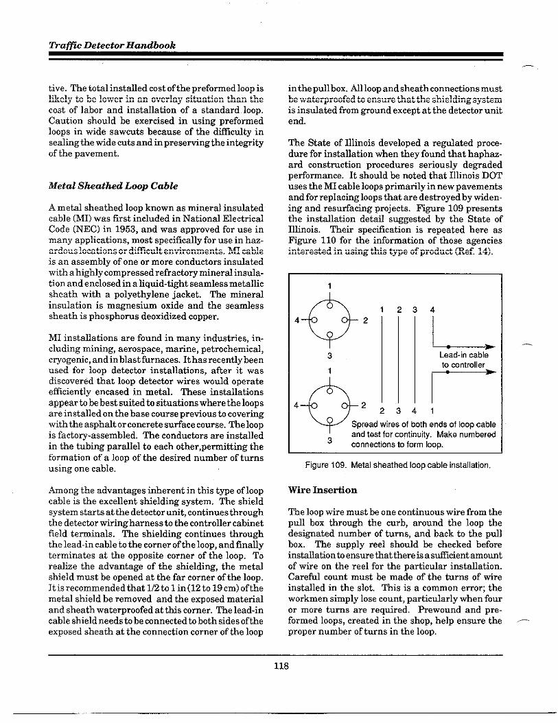
~aflc Detector Handbook
tive. The total installed cost of the prefomed loop islikely to be lower in an overlay situation than thecost of labor and installation of a standard loop.Caution should be exercised in using preformedloops in wide sawcuts because of the difflcdty insealing the wide cuts and in presefing the inte~ityof the pavement.
Metal Sheathed Loop Cabze
A metal sheathed loop known as mineral insdatedcable (MI) was first included in Natilonal ElectricalCode (NEC) in 1953, and was approved for use inmany applications, most specifically for use in haz-ardous locatlons or dfilcdt environments. MI cableis an assembly of one or more conductors instiatedwith a highly compressed refractory mineral insula-tion and enclosed in a liqtid-tight seamless metallicsheath with a polyethylene jacket. The mineraZinsulation is magnesium oxide and the seamlesssheath is phosphorus deoxidized copper.
MI installations are found in many industries, in-cluding mining, aerospace, marine, petrochemical,cryogefic, and in blast furnaces. It has recently beenused for loop detector installations, after it wasdiscovered that loop detector wires would operateefficiently encased in metal. These instillationsappear b be best suited to situations where the loopsare installed on the base course pretious to coveringwith the asphalt or concrete sutiace course. The loopis factory-assembled. The conductors are installedin the tubing parallel to each other, pemitting theformation of a loop of the desired number of turnsusing one cable,
Among the advantages ifierent in this type of loopcable is the excellent shielding system. The shieldsystem starts at the detector unit, continues throughthe detector wiringharness to the controller cabinetfield teminals. The shielding continues throughthe lead-in cable to the corner of the loop, and finallyterminates at the opposite corner of the loop. Torealtie the advantage of the shielding, the metalshield must be opened at the far corner of the loop.It is recommended that 1/2 to 1 in(12 to 19 cm) of themetal shield be removed and the exposed materialand sheath waterproofed at this corner. The lead-incable shield needs to be connected to both sides of theexposed sheath at the connection corner of the loop
—
in the pdl box. AR loop and sheath connections mustbe wate~roofed to ensure that the shielding systemis insulated from gound except at the detector unitend.
The State of Illinois developed a redated proce-dure for installation when they found that haph~-ard constmction procedures seriously de~adedpeflomance. It should be noted that Illinois DOTuses the MI cable loops primarily in new pavements
and for reulacin~ 100us that are destroved bv widen-. .ing and resutia~ing projects. F1gnre 109 presentsthe instillation detti suggested by the State ofIllinois. Their specflcation is repeated here asFigure 110 for the information of those agenciesinterested in using this type of product (Ref. 14).
1
34
LLead-in cableto wntroller
r
41w Spread wires of both ends of loop cableand test for continuity. Make numbered
3 connetiions to form loop.
Hgure 109. Metal sheathed loop cable installation,
Wire Insefion
—
The loop wire must be one continuous wire from thepull box through the curb, around the loop thedesi~ated number of turns, and back to the pullbox. The supply reel should be checked beforeinstallation b ensure hat there is a stilcient amountof wire on the reel for the particular installation.Careful count must be made of the turns of tireinstalled in the slot. This is a common emor; theworkmen simply lose count, particularly when fouror more turns are required. Rewound and pre-formed loops, created in the shop, help ensure the -proper number of turns in the loop.
118

—
Detector.Imtallation - Chapter 5
P.
,-.
,P
—
SPECIFICATI~ FOR METAL SHEAWEDLWP CABLE
The cable shall be#16 AW~th two, three, or four wnduaors as shown on the plans rated for 300 ‘volts with
outside diameters of 0.306, 0.337, and 0.353 inches respectively. The cable shall be furnished with a terminal
subassembly kit mmposed of a ~t, cap, sealer, and sleeves.
Installation shall mnsist of furnishing and installing Ml Cable Detector Loop on a bituminous or PCC base course
and revering it with bhuminous sudace course as desctibad and det6iled herein and in the plans.
TO install the cable, slanted holes of 1-inch diameter shall be dtilled through the base course. Where curb and
guner is present, the hole shall begin where the base course and guner meet and where curbs are not present,
the hole shall begin about 1-foot from the edge of the pavement. The cable shall not b installed until the Imp area
is ready to be avered (by the sutiace course) to minimize the traffic or asphalt truck running over the cable.
The installation of the cable requires the forming of the loop size including the leads to terminal end with some
spare, cutting the cable and immediately sealing the terminal ends to prevent absorption of moisture by the
mineral. The leads shall be bound together and insefled through the hole and psitioried in place to make sptices
in the propsed junction box.
The mble shall be s~ured to an asphaltic base course including the le6d5. The mrner radius for the loop shall
not be less that 6 inches. The leads shall be hund together with straps or fish tape rope (do not use wire) to
prevent cutting or damaging the polyethylene wver, Shovels of asphalt can be used to hold the cable in place.
The termination of the cable involves the stdpping of the cable ends, installation of, fittings, application, or
insulating compound and insalting the sleeve assembly according to manufacturer’s instructions. When the
sttipping is completed, the exposed Ml material should be sprayed with an insulating spray. The termination
procdure must be completed to avoid leaving the magnesium oxide exwsed and the conductor sleeves open to
allow moisture to enter them.
The sleevd wnductors shall be spbced together and metered to ensure a proper connection. The conductors
must be cleaned of the material coating to ensure a good connection while meteting. The conductors must be
soldered together and each conductor wrapped with two layers of rubber or vinyl electrical tape. The wrapping
shall wmpletely rover the soldered connection and the conductor sleeves for 1E inch.
A lmp test meter is used to ensure the loop will petiorm for detecting vehicles and after obtaining an acceptable
reading, the spliced wnductors and then sealed by centering them in a bottle mold and fill the mold wtih epoxy type
resin. The resin must completely rover the taps on the sleeves.
Any expsed copper sheath and the end seal pot shall be taped and coated with a silicone spray to prevent any
moisture contact with their sudaces. Any eletirical contact between the copper sheaves and the ends of the
cables will destroy the inductance reading,
NO splice shall be permined in the loop wire beyond the Iaad-in cable sptice or controller terminal when the Imp
wire is mnnecfed directly to the mntroller terminal.
The inductance and resistance of the loop as metered shall be within 10“/. of the calculated values for that loop as
shown on the loop detail sheet.
figure 1 t O. Example specification for Ml loop cable (Illinois Department of Transpotiation)
119

~a~c Detector Handbook
—.
The wire should be laid in the slot so that there areno kinks or curls. A blunt tool such as a paint stirrermay be used to push the wires to the bottom of theslot. Some agencies use a namow blunt wheel rolledalong the slot. A sharp instrument (e.g. screwdriver) should never be used as it easily penetratesthe wire insulation.
A special installation problem is encountered whenthe wire has to cross a pavement joint. men theloop is placed in a concrete roadway and crosses apavement joint, particdarly an expansion joint, themovement of one slab relative to another will causethe wire to break if some special treatment is notused to protect the wire. Additionally, one of themost common ftilure points is where the road sur-face meets the curb line. This area is subjected hboth vertical and hortiontal shifting.
There are two basic treatments for crossing thepavement joint. One method is to encase the portionof wire crossing the joint in some type of conduit asshown in Fi~re 111. Many agencies use rigidplastic conduit or flexible tubing. The State ofIllinois has used common robber garden hose insome of their installations.
Figure 111. Crossing pavement joints using tigid tuting.
The material that is used should be approximately3/4-in (1.9-cm) in diameter and at least 1 ft (30 cm)long. The conduit is placed in a cut which measuresI-U4 in (3.1 cm) tide and is 16 in (40 cm) long. Thedetails of this type of installation are shown inFigure 112.
—1 1/4” Sawcut3/4” Flexible Tuting
Loop Mr
Figure 112. Pavement joint crossing details,
k alternative method is to provide an excess ofwireat the pavement joint. The most common method for —protiding additional space for the extra wire is tomake the cut in the shape of a diamond. The cutshould be small, 2 in (5 cm) from edge to edge,excavated to the ftil depth of the sawed slot. Thisallows suficient space for an “S” shape of excess wireto be Dlaced in the cut out diamond as shown onFiWr~ 113. The diamond (and the adjacent joint, ifnecessa~) is filled with an appropriate sealant.
Pavement Joint
03~LT%r’
~gure113. Crossing pavement joints using diamond cut
-.
120

Detector Imtallation - Chapter 5
P
me two lead-in tires from the beginning and end-ing of the loop turns should be twisted together toform a symmetrically twisted pair from the loop tothe pdl box. Depending on agency policy, an addi-tional 3 to 5 ft (0.9 to 1.5 m) of lead-in pair slackshould be provided in the pull box.
Lead-in wire must be twisted to avoid crosstalk.~encies vaW on the specfled number of twists perfoot, ranging from two twists per foot to five twistsper foot. Manufacturers feel strongly that wiresshould be twisted a minimum offive to six ttists perfoot. Some agencies or contractors do not twist thewires because the twisted wires require a wider slotfor the lead-in wires, necessitating a larger sawblade than that required for the loop saw cut. Agen-cies that do not ttist the lead-in wires usually allowonly one pair of lead-ins per lead-in slot.
The correct and incorrect ways ofttisting the lead-in wires are shown in the top portion of Figure 114.
,-Mthough wires maybe twisted by hand, more effec-tive methods are also shown. Tke use of a twistershown at the bottom of the illustration til signifi-cantly speed up the process.
A multiple loop confiWration is frequently used tiemulate a long loop. For this type of loop system, theloops may be wired in series, in parallel, or in series-pardlel as discussed in Chapter 2. The wiringalternative to be used is determined by the loopsystem designer by considering such factors as sys-tem confi~ration, system requirements, and therecommendations of the selected electronic unitmanufacturer. The proper connections for each ofthe wiring alternatives are shown in Fi~re 115.
CROSS~G C-S
Typically, the ttisted lead-in wire must extend fromits lane location in the roadway across the curb orshoulder to the pull box. If a curb is present, passagethrough the curb is usually accomplished by using ajackhammer drill or punch-type tool to make theentry as shown in Fi~re 116. Liquid-tight flexibleconduit is then instilled in the hole so that it re-
n ceives the twisted loop lead-in wire from the sawcut.The conduit shodd terminate in the pdl box abovethe drainage to prevent moisture from entering the
Corred way to mist wire
Inmrrect way to twist wire
,f
Electrical Tape
1
figure 114. Method of twisting lead-in wires.
conduit. Fi@re 117 shows a cross-section view ofthe conduit connecting the saw cut h the pull box.~is conduit should be installed at the same timethat the pull box is installed.
Where the curb and Wttir section is relativelyshallow, the lead-in wire is placed in rigid conduitnear the edge of the roadway. The conduit is in-serted under the curb and ~tter as is shown inFi~re 118. The roadway end of the conduit isnomdly 2 in (5 cm) below the roadway sutiace.
In some cases, the crew will simply cut the curb andpass the lead-in wire through the curb. Unless thecut is made to a minimum depth of 18 in (45 cm)below the sutiace, this practicers not recommended.When the wires remain too close to the suflace, theycodd be severed by ~ass trimming or other mainte-nance activities
121
.\

~aflc Detector Handbook
—,
Parallel Loop Connections
~
ILL Pull BOXs
---- —-- ,
] Lead-l” cable-— ____ _J
Cut off and waterproof
shield and drain wire
Series Loop Connections
D
Pull BOXs
—---— ---
Fs,
m-
:
[J
F I Shielded
‘-‘r ‘--- d Lead-In Cable
Cut off and waterproof
shield and drain wire
SerieWParallei Loop Connections
n s
*
F
D- f!l(B&__ $/F
z
D
sF F 1 Shielded
--- —__ JLead-In Cable
D
F Cut off and waterproofs shield and drain wire
~-Wndi”g Direai.”
Figure 115. Loop wire winding diagrams for mutiloop installation,
Some agencies will drill through pavement beforereaching the curb and ~tter and will install aconduit beneath the curb section enroute to the pullbox. These agencies believe this to be a simplerinstallation process than dfilling through the con-crete curb. Other agencies claim it to be more
figure 116. Enty hole forcuti crossing,
dismptive to the pavement inte@ty. It does, how-ever, avoid any problems with the joint between thepavement slab and the curM~tter.
Pull BOX 3/4” or Iargar PVC conduit
:
Roadway
Expansion $oint W;e Slot
Hgure 117. LOOPlead-in wiras at curb section
122

Detector Iwtallation - Chapter 5
,.-,
Hgure 118. Detail forshallowcuh section.
men a curb is not present, a hole is dfiled throughthe edge of the pavement at a 45° angle. The top ofthe hole should beat least 6 in (15 cm) frOm the edgeof the pavement. The hole shodd be ali~ed with the
,-., pull box and be of stilcient she to accept an appro-priately stied conduit. FiWre 119 illustrates therecommended procedure.
Edge of
ShoulderEdge of Pavement
Mgid Steel ~+~ Min. 6“Conduit
/Base Pavement
Pull BOX Sawed Slot
Rgure119. Loop lead-in wires at pavement edge
~STALLATION OF -L BOX ANB
The pu~ose of the pull hox (also refereed to as a
,- ‘splice box,” ‘%andhole,” or”junction box’’) istohousethe splices between the lead-in wires from the loopand the lead-in cable to the controller cabinet.
Additiond pull boxes maybe reqtired at specfledintewals on long mns to the electronic units in thecontroller housing. ml boxes cm be made of con-crete, plastic, metal, or fiberglass.
For most installations, a standardNo. 3 or No. 5. pullbox, as shown in Fi@re 120, is used. The type ofhoxand ita location shotid be spectied and shown on theconstmction plans. Many agencies specify that thepull boxes, conduits, and curb cuts must be com-pleted before beginning the loop wire installation.Typical inatallationdetils are shown in FiWre 121.
Rgure 120. Standard pull box.
Hgure 121. Pull box installation detail.
123

fiaffzc Detector Handbook
Conduit is used to protect the lead-in wires and isconnected to the pdl box dting installation. Theconduit is inserted into the hole thro~h the curb orpavement and is connected to the pull box.
Mthough a 3/4-in (1.9-cm) conduit is adequate for asingle pair of lead-in wires (one loop), it is commonto use a l-in (2.5-cm) minimum conduit. Table 26provides the size of conduit for the number of loopconductors. Nomally, no more than two twistedpairs are installed in one sawcut slot; however,sometimes loop lead-ins are collected at an in-streetpull box (i.e., a pull box located in the travel way) andthen carried to the teminal pull box in a conduitunder the pavement.
At the roadway end, the condtit should be timi-nated 2 in (5 cm) below the pavement sutiace and anon-metallic bushing shodd be attached to protectthe lead-in wires. For futiherprotection, the lead-inwires shodd be taped for several inches on each sideof the bushing.
It is important to tag each loop lead-in wire identify-ing the loop number and the start (“S”)and finish(“F’) of each individud loop.
Table 26. Conduit size.
j co~::):i” I LOy~::tOrs j
Ill lt02
1-112 3t04
I 2 I 5 or more
Before the loop wires are sealed inthepavement, theloop and lead-in wire shotid be checked for continu-ity and resistance. Tests should be mn tith a looptester instrument capable of measuring electricalvalues of the wires and lead-ins. Measurementsshould be made of the induced AC voltage, induc.tances in microhenries, and the resistance of theconductors in ohms.
There are several types of loop testers to measureinductance, such as the one shown in FiWre 122, In
:,
Figure 122, Loop tester.
addition, the inte@ty of the wire insulation shouldbe checked. This can be accomplished with amegohmeter (popularly called a “megger”). Apply-inga megger between each end of the lead-in and the ,_nearest reliable electrical Wound (e.g. street light,fire hydrant, etc) the megger reading should be inexcess of 100 megohms under any condition.
The wiring dia~am of the plan set or the inspectionrepoti shodd include a table of calculated values ofthe inductance in microhenries and resistance inohms for each loop. ho values shodd be shown: oneat the Pull box without the lead-in cable, and thesecond at the controller cabinet with the lead-incable connected. The loop installation is acceptableunder the following conditions
.
.
.
.
Induced Voltage: There is no deflec-tion of the pointer of a volt meter.
hductance: The inductance readingon the loop tester is within 10 percentof calculated value.
Leakage to Ground: Using a 500 Vmegger, the resistance to ~ound ofanewly installed loop exceeds 100megohms.
Loop ~sistanc~ The readingmr an —ohm meter is tithin 10 percent of thecalculated value.
124

—
Detector Imtallation - Chapter 5
The metered values obtained from the test should berecorded on the tiring plan (or on an InspectionReport described later under Find Tests and RecordKeeping). This information wfil be used for fnturetesting and maintenance. Ref. 32 describes a proce-dure used by the California Depatiment offianspor-tation to test the operation and sensitivity of a newloop installation.
One of the major challenges in detectir technologyhas been to protect the loop wires from breakage,moisture, and from floating to the top of the sawcutand becoming mlnerable to the ravages of trtilc.The sealant used is of primary importance, as is thetechnique of its application.
The several types of sealants, the application of thesealant, and the alternative methods of protectingthe wire tithin the slots are discussed below. &tin,it should be stressed that matching the proper seal-ant with the type and condition of the roadway,together with appropriate, well supervised installa-tion techniques, are the key factors to effective,maintenance-free detector operation.
Types of Sealants
During the 1970s, the types of sealants used wereabout equally divided between asphalt-type andepoxy-type sealants, Early asphalt-based sealantshad to be heated before application. These were soonreplaced with Wn-~ade asphalts marketed as cadk-ing compounds. These, in turn, were replaced byepoxy sealants. The early epoxies were too hard andbrittle to adapt well to shifts in pavements and wereexpensive and dfilctit to apply.
Today, there is a tide variety of sealants producedbased on each manufacturer’s proprietary fomda.These suppliers strive to produce a sealant thatperforms according to various desirable characteris-tics. For example, the sealant should be hard enoughto resist the penetration of foreign materials andstreet debris such as nails or metal fra~ents thatmight pierce or break the wire, yet the sealant shoddbe flexible enough to deform without cracking duringthemal expansion and contraction. Sealants shouldbe able h tithstand the corrosive effects of road
salts, gasohne, anti-freeze, transmission fltids, br~efluid, etc. commody found on roadway sutiaces.
bother critical characteristic is that the sealantshotid have good adhering properties with similarcontraction and expansion characteristics to that ofthe highway matetial in which it wfll be installed.For asphalt-type roads which tend to move, rubber-tied asphalt, polysulfide-based sealants, and flex-ible epofies are usually recommended. These typescan also be used with concrete along with the morebrittle-type epoxy.
Other advantages sought in selecting sealants arerapid curing rate and the abfiity to be applied todamp sufiaces. A rapid curing rate is desirablebecause it will minimize the amount of time that alane must be closed to traffic. During the saw cuttingoperation, a water-cooled blade is generally used,and even though the slot may be cleaned tith com-pressed air, some residual dampness may remain.In such cases, it is desirable to be able to apply thesealant directly to damp suflaces rather than firstdrying them with butane torches, which is timeconsuming and may damage the asphalt sutiaces.
Sealant applications are characterized as either coldpour or hot pour types. Cold pour types includepolyester resin, epoxies, polysulfide bases, and rub-berked asphalt. The hot pour varieties include hotpitch, asphalt, and rubberized asphalt. Both sealanttypes must not revert to their liqtid state during hotweather, because this will allow the loop wire to floatto the sutiace. Sealant shotid always befltid enoughduring application to level itself on a horkontalsutiace, but should not mn when applied on aninclined sufiace. Careful attention must always bepaid to applying the sealant in strict adherence tothe mantiacturer’s instmctions.
Hot tar continues to be used because of its low initialcost. Several States, however, have prohibited itsuse due to the high percentage of faflures and thedanger and inconvenience to workers during appli-cation. The heat involved (sometimes exceeding 500“F (260 ‘C)) in the application frequently breaksdown or deforms the insulation of the loop tire,diminishingits instiatinginte~ty. In addition, hottar sealant becomes soft in hot weather and allowsvehicles to track the tar from the sawcut. Rocks andother debris can penetrate the soft sutiace andeventually damage the loop wire insulation.
125

Trafic Detector Handbook
Rubberized asphalt appears to be the sealant ofchoice, particularly for asphalt pavements. It is nec-essary to ensure that the wire spectiled for the loophas insulation capable of withstanding the 400 ‘F(205 ‘C) application temperature of the mbberizedasphalt sealant. Epoxies, however, have overcomesome of their early drawbacks and are now formu-lated to provide a geater de~ee of flexibility.
sented in Fi~re 123 (adapted from Ref. 33). Inretiewing the documentation of these State tests, itwas interesting to note that a product that scoredhighest in one State test was considered unaccept-able in anotherState test. ~is leads to the concis-ion that the disparity in test results is most p~Oba.
bly caused by differences in geo~aphic and climaticconditions, as well as methods of testing the prod-ucts. However, most agencies are consistent in
A number of States have conducted extensive tests produd approval critetia. ~is, in turn, suggestsof the various, commercially avaflable sealants prior that agencies should periodically validate their teststo listing the acceptable sealant products in their and test procedures b ensure that their specWlca-sp edifications. A typical State spectilcation is pre- tions are appropriate.
TRAFFIC LOOP SEALANT SPECIFICATION
Section XXX.XX Tratiic LooDSealant Material shall bean epxyresin system oraplyester system designedspecifically tomeetthe physical propeflies forsealing traticloop pavement cuts, Thee~xy resin system shall bean unfilled system intended to be used withan equal volume ofclean, oven-d~ sand, Thesystem shall bond toeither poflland cement concrete ortituminous concrete, shall beunaffetied byenvironmental renditions, andshall have adieledtic strength sufficient toallow thetraffic loop cooperate as intended. Wsmsity of the mixtureshall be such that it is easily pourable into the saw slot and sufficiently flowable to enmse the ele~tical wifing,
(a) FOOXVResin Svstem shall beatwo component material con forming to the following requirements basedonthe epoxy wtihout sand (except for the pot ife requirement):
PROPERTY TEST METHOQ MEASUREMENT REQUIREMENT
Pot Life at 77” F w/Sand ASTM C881; f11.2 Minutes 12 MinimumInitial Cure Time at 77° F Hour 1 MaimumHardness, Shore D ASTM D2240 Number 25 to 65Elongation ASTM D 638 Percent 50 MinimumWater Absorption in 24 hours ASTM D 57o Percent 0.5 Maximum3Y. NaCl Absorption in 24 hours ASTM D 57o Percent 0.5 MaimumASTM #3 Oil Absorption in 24 hours ASTM D 57oGasoline Absorption in 24 h~”r~
Percent 0.1 MaximumASTM D 57o Percent 1.0 Maximum
(b) Polyester Svstem shall beatwocomponent matetial con forming tothefollowing requirements:
PROPERV TEST METHOD MEASUREMENT REQUIREMENT
Pot Life at 77° F w/Sand ASTM C881; $11.2 Minutes 12 MinimumInitial Cure Tme at 77” F Hour 0.75 M~imumHardness, Shore D ASTM D2240 Number 25 to 65Elongation ASTM D 638 Percent 15 MinimumWater Absorption in 24 hours ASTM D 57o Percent 0.2 Maximum3Y. NaCI Absorption in 24 hours ASTM D 57o Percent 0.2 MaximumASTM #3 Oil Absorption in 24 hours ASTM D 57oGasoine Absorbtio” in Z4 hO”r~
Percent 0.02 M~imumASTM D 57o Percent 0.8 Maximum
Rgure 123. Typical State sealant specification.
,..—
.—
126

Detector Iwtallation - Chapter 5
,-,
● - Loop Wres m - sealant
figure 124. Methods of applying sealant.
Techniques for *slant Application
The commonly used practices for sealing the loopwire are depicted in Fi~re 124. One procedure(Fi@re 124 left view) consists of applying a layer ofsealant h the floor of the saw cut after thoroughlycleaning and drying the slot, The loop wires are then
n laid in the slot and covered with a second, final layerof sealant. This method tends to fix the position ofthe loop wires in the middle of the saw cut, protect-ing them on the top and bottom. Some agenciesbelieve that this procedure, Nthough more costly,protects the loop wires from water intmsion.In the technique shown in the middle of Fi~re 124,the wire is simply laid in the slot and covered withsealant. There is no way to control the positioning ofthe wire in the slot. In a three-tire installation, thethree layers of wire may fom a triangle on thebottom of the slot or may stick over each other.
The backer rodsealant combination shown in Fig-ure 124 (right view) is based on the theory thatstresses on sealant during elongation are reduced ifthe sealant has less depth. With this method, thewires are placed in the slot and then a backer rod(generally a closed-cell polyethylene rope) is forcedinte the slot over the tires. The remainder of the slotis then filled with sealant. The backer rod assures ashallow layer of sealant reducing tensile stressesand leaving the wires free to adapt to shifiing of thepavement. b alternative method that is becomingincreasingly popular is b insert short pieces of the
,= backer rod (approximately one inch) every foot ortwo to anchor the wire in the slot before applying thesealant.
mere seems to be no published evidence of thesuperiority of one method over the other. In reality,most detector instilers aflee that the neat arrange-ment of tires as shown in many published illustra-tions is simply not indicative ofactud installations,rather, the lay of the tires is random in the slot.~ey a~ee that complete encapsulation by thesealant is seldom achievable. Some installers alsoar~e that placing sealant in the bottom of the sawcut (left tiew in Fi~re 124) before laying the wire istime-consumingand reqtires more road-closure time.Installers indicated that even when this method ofinstallation is specified, it is unlikely to be followedudess an agency inspector was actually overseeingthe installation. This is another illustration of theneed for careful installation inspection.
On the otherhand, proponents ofthismethodreportthat the extra protection of the bed of sealant on thebottom of the sawcut prevents the intrusion ofwaterthrough small pavement cracks. It also avoids thepossibility of sha~ edges or rocks becoming dis-lodged and piercing the installation. Others feelthat this is a remote possibfiity, patiicularly if thesawcut is well cleaned of debris. On the other hand,some agencies specify the use of a layer of sandrather than sealant at the bottom of the saw cut.This does provide a smooth bed at the bottim of thesaw cut but does not prevent the intrusion of waterthrough pavement cracks.
The amount of sealant to be applied should besufficient to completely fill the saw cut, but notovefidl. A trowel or other tool shodd be used toensure that the sealant is slightly below the pave-ment sufiace and that any excess sealant is re-moved. Fi@re 125 shows the result of poor installa-
Rgure 125. Example of poor sealant application.
121
,—

fiafic Detector Handbook
—
Figure 126. Crew applying sealant.
tion procedures. It sho’ws oveflllling, undefilling,and air bubbles in the sealant. Ml three conditionscan lead to detector failure and should have beencorrected during the installation process.
Sealant may be applied with a special applicator asshown earlier in FiWre 104 or by hand directly froma container as shown in FiWre 126. In this filustra-tion, one member of the crew is placing the lead-inwires in the slot, while another worker is pouring thesealant into the sawcut. Note that a paint stirrer hasbeen inserted in the slot to hold the tire down whilethe sealant is being applied. Other techniques canbe used (e.g., hacker rod strips, nylon rope, etc.) tohold the wire securely in place as sealant is added.Figure 127 shows the crew properly finishing the
Rgure 127. Enishing the sealant application
sealant application. The sealant has been trowelledin the slot to remove any excess, talc is being dustedon the fresh sealant, and splashes of sealant arebeing removed from the pavement area.~er the sealant has been applied and before open.ing the lane to trafic, a number of agencies and loopinstallers coat the newly applied sealant with sandor talc. This prevents tracking of the sealant duringits curing process and allows earlier opening of thetrafic lane.
Some sunbelt agencies use sand as the sealant.~er the wire is placed, sand is timped into the slot.The sand is easily tracked out of the slot and thewires may become dislodged. Therefore, this prac-tice is not recommended.
SPLIC~G m m
The splice between the loop lead-in tire and thelead-in cable to the detector unit in the controllerhousing is a critical step in the installation process.The splice should be located in the pull box and ,_should be the only splice in the loop system. Thesplice is frequently the cause of detector failure;however, if proper splicing procedures are used, thesplice connection should not be a problem. There aretwo basic steps to a splice; the physical connection ofthe wires and the environmental sealing of theconnection.
Connecting the Wires
The methods used to physically connect the lead-inwires from the loop with the lead-in cable varyamong agencies. The two preferred methods aretwisting and soldering or crimping and soldering,Most detector manufacturers specity a solder con-nection in their installation procedures. The arW-ment for soldering is that it protides a connectionwith lower resistance and has less susceptibility tocorrosive de~adation. The soldered connection will,therefore, require less maintenance in the long run.
While pressure connectors (crimping) without sol-dering may have been generally acceptable in thepast, the use of solid state electronic apparatus nowmakes soldered connections preferable. These elec- —tronic devices operate at ve~ low voltage levels andminimum current loads. Because of this, they are
128

Detector Imtallation - Chapter 5
susceptible to even slight voltage drops which occurwhere poor electrical connections cause high resis-tance in a circtit.
To make the physical connection, about 8 in (20 cm)of the outer covering of the lead-in cable is strippedaway. One wire is clipped about 3 in (7.5 cm) shofierthan the other. About 1-1/2 in (4 cm) of the tireinsulation must be sttipped away from the cablewires and the loop lead-in wires. The appropriatewires are then twisted together (end to end) orcrimped with a non-insulated butt connecbr. Caremust be exercised to assure that the comect wiresare connected.
If the connections are to be cfimped, it is stronglyrecommended that a high quality pressure crimpingtool be used to provide a unifom 360° crimp. Caremust be exercised to ensure that only bare wire, andnot the adjacent insulation, is in the connector. Theindividual connected splices should be staggered sothat the spice does not become too bulky. Eachconnection should then be soldered using 60/40 (titilead) resin core solder. The Ontatio Ministry offiansport, on the other hand, specifies the use of60/40 (lea&zinc) resin core solder (fif. 31). The proce-dures for both twisted and crimped splices are de-tailed in FiWre 126.
Environmentally Sealing the SpEce
Once the wires are firmly spliced, it is essential thatthe sphcebeentionmentilly sealed against weather,moisture, abrasion, etc. A variety of methods areused, including heat-shrinkable tubing, specialsealant kits, special fores to be filled by sealant, pillbottles with slot sealant, tape and coating, etc. Anymethod is acceptable as long as it protides a soundentironmentd seal.
men using heat shrinkable tubing, the tires mustbe inserted in the tubes before they are joined. hosmall tubes are used for the individual tires and onelarge tube to cover the entire splice area. The wiresare connected and soldered as described earlier, andthe small tubes are centered over the connectionsand are Wadually heated by an electric heat gan orbutane torch until the tubes have shmnk uniformlyaround the wires. The larger tube is now positionedover the splice and heated in the same manner. Caremust be exercised to avoid hurting the wire insula-
$tep 1. Sttip loop wirss and lead-in cable
Lead-In Cable Loop Wire
Step 2. Conned and solder
Twist bare conductorsCrimp bare condutiors
togethertogether with an
uninsulated butt connetio
~ e~~
and solder with 60/40 ‘R and wider with 60/40
[tin/lead) resin solder (tin/lead) resin solder
Step 3. Insulate each solder joint separately
Electrical Tape OR Shrink Tube
~~
Step 4, Environmentally seal total splice
Rgure 126. Sphcing loop wire at pull box.
tion or the cable jacket. Once the tubes have beenshrunk over the splice area including the cable end,a secure environmental seal has been established.
Special sealant kits are commercially available.These kits may have one-part or two-part sealants.One-pati sealants are ready to use. Two-part seal-ant kits usually contain the resin and hardener inseparati compatiments of a plastic package. Theseal between the two patis is broken and the twocomponents retied. The package is then cut openand the sealant is formed over the splice area. It isimpofiant to ensure that the mtiture penetratesbetween the wires.
& alternate process uses a form around the splicearea. A liquid or pourable sealant is introduced intothe form. Care should be exercised to ensure that
129

~afic Detector Handbook
.-
the fom is totally fdled with sealant and there areno voids within the splice area.
A ve~ simple encapsulation process consists ofusing a common dmg store pfll bottle as shown inFi~re 129. The tires are spliced side by side ratherthan end to end. After the wires are ttisted andsoldered (some agencies add a wire nut or tape thejoint), the completed splices are inserted into a pillbottle that has been fdled with sealant or electficdepoxy. The detils of the pill bottle splice areillustrated in Fi~re 130.
Rgure 129, Rll bottle splice
Some agencies stfll use electficd tape to seal thesplices. This procedure is not recommended. How-ever, if tape is used, it should be high quality electri-cal tape. Each wire connection should be tapedseparately and then the entire splice area covered byseveral layers of overlapped tape. A wate~roofsealant should then be applied to the entire tapedarea.
In general practice, the lead-in cable from the pullbox to the controller cabinet is buried bare or placedin conduit below the sutiace of the ~ound. In eithercase, the cable should be buried in a trench at least
Rgure 130, Pill bottle sphce details.
18 in (45 cm) below the surface. If condtit is used, itshould be wate~roofed.
Nenchingis the most common method for installingunderground cable (see Figure 131). The construc-tion plans should specify how deep to trench. Afterplating the cable in the trench, it should be back-filled inlayers not to exceed 6 in (15 cm). Each layer
figure 131. Cable trenching.
130
. ,.. ,..

Detector Imtallation - Chapter 5
should be compactad with mechanical tampers hthe approximate density of the sumoundingWound.men the bactilll is complete, there should not beany extra material left over.
The lead-in cable till end inside the controller cabi-net at the field teminal strip as shown in F@re132. k excess of 18 in (45 cm) of cable should beprotided in the cabinet housing. Note that theshield of the cable in this example is connected to thethird terminal adjacent to the loop terminations. Adfierent procedure is espoused by one manufac-turer who states that the cable shield shodd beinsulated from wound and floating at both ends (atthe cabinet and in the pull box).
Most manufacturers recommend Wounding at thecabinet (i.e., connecting the shield h the terminal inFi~re 132) andinsdatingthe end of the cable in thepull box. This allows any electrical disturbance orinterference ti be safely Wounded without affectingthe loop lead-in cable.
Pbtic Tub
Rgure 132. Held terminal strip,
The Ontario Ministry of ~anspoti (unti 1990) rec-ommended a contra~ procedure, that is, ~oundingat the splice point in the pull box and cutting off theshield in the cabinet. (See Append&N, page g-36.)They reversed this procedure in 1990, to mound theshield in the cabinet and instiate the shield in thepull box.
NEW avoids the issue by indicating that “Field in-stallation practices or detector unit desi~ mayrequire Wounding the shield of the loop lead-incable. Such Wounding should be in accordance withthe detector manufacturer’s recommendation;
me loops =e capacitively coupled to the earth andreceive a voltige surge whenever lightting currentsenter the wound nearby and cause an eatih voltagetise. These surges may need to be suppressed wherethe cable enters the controller cabinet or wherethese circtits enter the detector ufits. Back-to-backzener diodes or neon lamps usuflly provide ade-quate protection.
Most modern detector units have bufit-in lightningprotection features. Even so, some agencies inlightning prone areas (specKlcally Ontario, Canada(Ref. 31) and Florida) recommend that additiondprotection be added, such as two neon lamps or twogas fdled, surge voltnge protectors connected to theterminal strip as shown in Fignre 132.
F~fi TESTS ~ ~CO~ ~EP~G
Find tests should be conducted after dl loops andcables have been installed. The initial tests, de-scribed previously in this section, should be re-peated to ensure the detector installation is per-forming as expected and is folly operational after allcables have been buried.
The result of the tests should be recorded on aninstallation data sheet such as that shown in fi~re133. Any mod~lcation made to the original plandrawings should be notid, dated, and retained as“As Btilt” plans.
Exact readings from the tests and the modified plansshould be verified by the inspector. These recordswfll comprise the history of the particular detectorsystem and will fom the basis for any future main-tenance or reptir actitity.
131
—

Dafic Detector Handbook
LOOP INSTALLATION DATA
Date:
Weather:
Approximate Temperature:
Pavement Condition: Wet (_) Dry (—)
Location:
Drawing Number:
Contractor:
Material:
Loop Wire:
Lead-In Cable:
Pull Box:
Splice Kit:
Conduit:
Curbside to Pull Box:
Pull Box to Cabinet:
Sealant:
Loop System:
Position:
Configuration:
Estimated Measured
Twisted Lead-In Length:
Lead-In Cable Length:
Inductance:
DC Resistance:
Leakage Resistance:
Comments on Workmanship:
Remarks:
Recommendation:
Inspected By: .—.
—Hgure 133. Typical installation sheet.
132

Detector Imtallation - Chapter5
GE~W ~STALLA~ON G~EL~S signalized intersections under a wide variety of cir-cumstances. For specific installations, the actual
A set of general installation @idelines is presented design, installation procedures, testing, etc. shouldin Table 27. It is emphasized that these are general be followed. These ~idelines were developed fromguidelines for the installation of loop detectirs at Refs. 34 and 35.
Table 27, General installation guide~nes.
Design
. The width of the loop should be tailored to the width of the lane
. Loops should not ba over 6 feet (1.8 m) wide in a 12 foot (3.7 m) lane.
. Loops should not be less than 5 feet (1.5 m) wide (height of detection is approximately one half to twol thirds ofthe loop width).
All loops should have a minimum of two turns of wire in any aawcut except in a quadruple.
. One additional turn of wire may& specified forloopa inatallad in reinforwd concrete orovar2 inches (5cm) deep.
Installation of Loop Wire and Lead-in @bles
. The corner of loop sawcuts should be cored, chiselad, beveled, or diagonally cut to eliminate sharp turns.
. Sawcut should be deep enough to provide for a minimum of 1 inch (2.5 cm) of sealant over uppermost wire.
. If 1/4 inch sawcut is to be used, seled wire size to allow encapsulation of the wires(AWG#14or#16).
Loop wires should have a high qualky insulation such as cross-linked polyethylene or polypropylene.
. Wire should be laid in sawcuta in the same rotation (clockwise or counter-clockwisa) in a loop.
. Loop wires should ba tagged to indcate start (S) and finish (F) and should indicate the loop number in the pullbox to facihtate series splicing with alternate polarity connedons.
. Sawcuts for the loop lead-in wire should b at least 12 inches (2.5 cm) from adjacent loop ed gas.
. The loop lead-in wire from the loop to the pull box should be twisted a minimum of 3 to 5turns prfoot.
. Splices of loop lead-in wire to lead-in (home-run) cable must be soldered, insulated, and waterproofed to ensureenvironmental protetiion and proper operation.
. The Iaad-in cable should be twisted, shielded, and waterproofed.
. The cable selected should have a polyethylene jacket.
For most installations, the lead-in cable should not be connected to eaflh ground at the pull box, only insulatedand floating. Manufacturer’s recommendations should be followed concerning whether the cabinet end isgrounded or not (per NEMA). .
133

Daflc Detector Handbook
Table 27. General installation guidelines. (Continued)
Testing
. PriOr tOfilling sawcuts with sealant, loops should be checked wfih an ohm-meter for continuity and loop and lead.ins in pull boxes should be checked with a 500 V DC megger to confirm insulation resistance >f 00 mgohms.
. Loops should be checked with a drecf reading inductance inter at the pull box to confirm the number of turnsof wire in any loop. The following formula was developed to provide a simple method to calculate the approxi-mate inductance of any loop con figumtion andlor confirm the number of turns in the loop,
Inductance (L) = K x fact of sawcut
No. of Turns ...K. phfi... .. ........1 ........ .. . 0.5..... ........2 .......... . 1.5..... ..... ...3 .......... . 3,0..... .. ......4 ..... .. .... 5.0..... .. ......5 ..... .. .... 7.5
. inductance meter should also confirm alacttical splica configuration of multiple loops to allow selection of propersensitivity setting on detector unk.
Sealant
. Loop saalant should ba selected to insulate and protect wires,
. Loop sealant should encapsulate loop wires to tha fullest extent possible,
. At least 1 in (25 mm) of sealant should couer the loop wires (i.e., do not allow wires to float).
. The sealant selected should adhere to asphalt or concrete, but not necessarily to both.
. For installation in an existing roadway, Ioopsealant should be poured to within 118inch of surface. Forinstallafionprior to overlay, the sawcut should be filled completely before paving.
Connections
. All spade lug connections in the loop circuit should be soldered,
. Multiple loops connectad to the sama datecforchannel should be connectad in series orsetiaslparallal. (Somemanufacturers dispute the use of serieslparallel.)
. Confirm seties splice with inductance measurement ptior to connecting to lead-in cable.
. Multiple loops connected to the same detector channel ehould be connected with alternate polarty (clockwise- counter clockwise) to improva noise immunity and atabihty.
. Loops in adjacent lanes should be connected to the same mukiple channel detector unit.
,. Fnr mn.a avan+ ,,al, ,6. Af i“A, ,n+. ”ao , ,.a fimnn”A; ” n
—.
—
134

Detector Iwtallation - Chapter 5
DETECTOR ~STfiUTION&TERNAT~S
Agencies and manufacturers continue to search forbetter ways to instil detectors. The following sec-tion describes two methods that have been devel-oped, tested, and are cmently operational. Notethat conventional loop detafls such as splicing, test-ing, etc. described earlier dso apply to the followingalternative methods.
SH LOOPS
In the early 1980’s, the Puetio Rico Highway Author-ity and the Depatiment offianspotiation and PublicWorks began to experiment with placing loop detec-tors in heatily reinforced precast concrete slabs forinstallation in bituminous pavements (Ref. 36).Earlier experimentation with loop detectors placedin cast-in-place concrete slabs 12 ft (3.7 m) in widthand 6 ft (1.6 m) in length were unsuccessfd due tothe difflcdties in maintaining “traffic during therelatively long curing period. Because of the she andweight, these slabs could not be precast.
me use of magnetometer detectors was also tried.They were found to be unsatisfactory because of theprotimity of the Island of Puerta Rico to the equato-rial line, which resdted in erratic behavior of the de-
Smdler utittied slabs were selected as an effectivedesiW for use in Puerto Rico. They have been usedextensively for left-turn lane detection, off-rampdetection, artetial detection, and system detection.
The find design of the precast or cast-in-place loopslabs (both types are used) is 4 ft (1.2 m) square and8 in (20.3 cm) deep. A circdar slot 40 in (102 cm) indiameter, 3 in (7.6 cm) deep, and U2 to 3/4 in (13 to19 mm) wide is impressed in the concrete to housethe conductors foming the loop.
Five turns ofwire are standard in these installationswith three turns considered to be the minimum ac-ceptable. (Adequate detection has been obtainedwith up ti 1,000 fi (300 m) oflead-in cable between
fi, the PU1lbOx ad the detector unit.) After the wire iswound in the slot, a 5/8- to 7/8-inch (16-to 22- mm)
nylon rope is forced into the slot on tap of the loopwires and then the slot is filled with an asphaltsealant. A l-in (25-mm) fletible metallic conduct isused to house the lead-k wires leading to the pullbox.
As shown in the plan detnils in Figure 134 (from Ref.36), the slabs are provided with fourliftpoint deticesfor handling during the original installation and forresetting in the case of overlays. These slabs can beeasfly handled bytwo men and a small loader-back-hoe combination.
Hot-poured asphdtic sealant and sflicone sealanthave both been used successfdly. Au emulsifiedasphalt sealant is dso being tested as it is lessexuensive and does not need to be heated. EDOXY. .sealant has not been used for this pu~ose as th~stype of sealant may make reentry into the slot forrepnirs more dificdt.
Steel Bars #5 Grcular Slot
@ 6“ Centers\ 4V;Diameter
4Utinb Insefl
hfting InsenLoop Wre (5 Turns)
... ,. ‘... . .
Section A-A
Steel Bars #5@ 6 Centers
Rgure 134. Plan details of slab loop installation.
135

fia~c Detector Handbook
Mthough these slabs were originally intended foruse on bituminous pavements, their petiomanceand ease of maintenance have led to the use of slabson new and existing PCC pavements. On existingPCC pavements, an oversize square is cut out of thepavement and the precast slab is instiled withconcrete backfill.
PuertoRlco usesnon-reinforced concrete pavementa.~erefore, on new PCC pavements, a @d of rein-forcing bars is placed at the bottom of the new slabwhere the loop is to be placed prior to the pouring ofthe concrete. After the pour, afom for the slot is im-pressed into the fresh concrete.
Precast loop slabs have been used successfully infour basic confi~rations as shown in FiWre 135:actuation (LC-1), directional (LC-2), presence (LC-4), and high-speed detection (not shown on draw-ings). me loops have been connected in series andin parallel and have been used with standard andself-tuting detector units
——
LC-1
101LC-2
t
LC-4
Rgure 135. Precast loop slab configurations,
~eyhave been instiled at isolated intersections aswell as in coordinated systems. In coordinatedsystems, they have been used for bothlocd detectionand as strategic system sensors to feed informationb the master controller for traffic responsive opera-tion.
By 1988, there were more than 1800 slab loop detec-tors installed in Puerto Rco. Ger a 5 year periodthere had been no traffic or pavement-induced fafi-ures. On three occasions the lead-in wires had beendamaged by excavations in the sidewalk or adjacentpavement areas, mere were dso 13 incidence offailure in the wire insulation caused by a mantiac-turing error.
It is important to note, that, although Puetio ficoexperiences heavy rainfall, the annual temperatureranges between a low normally about 60 ‘F (16 “C)and a high nomally below 97 “F (36 “C); conse-quently, there is no freeze-thaw problem. ~is couldpossibly affect the use ofthese slabs in colder climes.
me failures that occumed provided the oppotiunity _to demonstrate the ease with which loops can berepaired. With a screwdriver or simflar tool, thenylon rope is pried from the slot and, by pulling onthe rope, the rope and sealant are removed. meconductor wires are then removed from the slot.New conductors, rope, and sealant are theninstdledand an epoxy-encapsulated splice is made at thenearest pull box. ~is completes the repair withlittle disruption to traffic.
Experience tith the loop slabs have been very suc-cessfti in Puetio Rico, A typical installation on anoff ramp and in a lefi turn lane is shown in Fi~re136. In the mid-80’s the cost in Puerto Rico wasapproximately $350 per loop including the slab,installation, conduit, wiring to the nearest pull box,and the splice at that pull box.
Older si~al projects with sawed slots in the pave-ment are being retrofitted tith precast slabs toprevent the deterioration and intemption of sem-ice due to loop failures. Mthough a fomd benefiticost comparison between the precast and the sawedloop detectors has not been conducted, the zerofailure rate of the precast system duringa 5 year op-erating period is considered sufficient justification —for Puerto Rico to adopt the precast loop as standarG,practice.
136
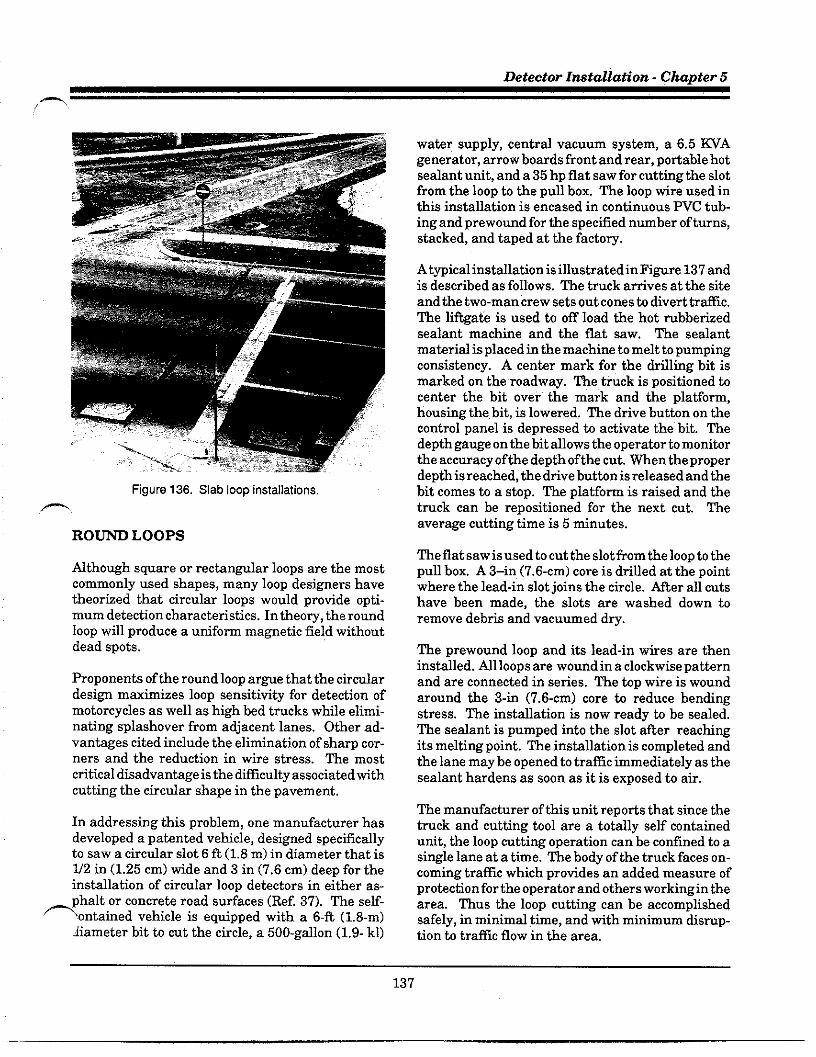
Detector Imtallation - Chapter 5
f >
Hgure 136. Slab loop installations
,+.
RON LOOPS
Mthough square or rectan~lar loops are the mostcommonly used shapes, many loop designers havetheorked that circular loops would protide opti.mum detection characteristics. In theory, the roundloop wfil produce a unifom magnetic fiel,d withoutdead spots.
Proponents of the round loop ar~e that the circulardesi~ maximizes loop sensitivity for detection ofmotorcycles as well as high bed trucks while elimi-nating splashover from adjacent lanes. Other ad-vantage cited include the elimination of sham cor-ners and the reduction in wire stress. me mostcritical disadvantage is the dificulty associated withcutting the circdar shape in the pavement,
In addressing this problem, one manufacturer hasdeveloped a patented vehicle, designed spec~lcdlyto saw a circdar slot 6 ft (1.8 m) in diameter that isU2 in (1.25 cm) tide and 3 in (7.6 cm) deep for theinstallation of circular loop detictors in either as-phalt or concrete road sutiaces (Ref. 37). me self-
=~ontained vehicle is equipped with a 6-ft (1.6-m)Iiameter bit to cnt the circle, a 500.gdkm (1.9- kl)
water supply, central vacuum system, a 6.5 WAgenerator, arrow boards front and rear, potiable hotsealant unit, and a 35 hp flat saw for cutting the slotfrom the loop to the pull box. me loop tire used inthis installation is encased in continuous PVC tub-ing and prewound for the specified number of turns,stacked, and taped at the facto~.
Atypical installation isillustratedin Fi@re 137 andis described as follows. The truck amives at the siteand the two-man crew sets out cones to divert trtilc.The liftgafe is used to off load the hot mbbetiedsealant machine and the flat saw. The sealantmaterial is placed in the machine to melt ta pumpingconaiatency. A center mark for the drflling bit ismarked on the roadway. fie truck is positioned tocenter the bit over the mark and the platform,housing the bit, ia lowered. The drive button on thecontrol panel is depressed to activate the bit. Thedepth gauge on the bit allows the operator to monitorthe accuracy of the depth of the cut. men the properdepth is reached, the drive button isreleasedandthebit comes to a stop. me platfow is raised and thetmck can be repositioned for the next cut. Theaverage cutting time is 5 minutes.
The flat saw is used to cut the slot from the loop to thepull box. A 3–in (7.6-cm) core is drilled at the pointwhere the lead-in slot joins the circle. ~er all cutshave been made, the slots are washed down toremove debtis and vacuumed dry.
The prewound loop and its lead-in wires are theninstalled. Ml loops are wound in a clockwise patternand are connectid in series. The top wire ia woundaround the 3-in (7.6-cm) core to reduce bendingstress. The installation is now ready to be sealed.The sealant is pumped into the slot fier reachingits melting point. The installation is completed andthe lane may be opened to traffic immediately as thesealant hardens as soon as it is exposed to air.
The manufacturer of this ufit repotis that since thetruck and cutting tool are a totally self contiinedunit, the loop cutting operation can be confined b asingle lane at a time. The body of the truck faces on-coming trafic which protides an added measure ofprotection for the operator and others working in thearea. Thus the loop cutting can be accomplishedsafely, in minimal time, and with minimum disrup-tion to trafic flow in the area.
137

Daflc Detector Handbook
~ST&UTION OF
Hgure 137. Installation of round loops.
.—
WG~TOMETER DETECTORS
Typical ma~etometerinstdlations forvariouslaneconfigurations are illustrated in Fi@re 138. meprobes are placed beneath the roadway sufiace incored holes. The optimum depth and placement ofthe probes depends on the type of detection reqnired(see Chapter 4).
Mter the pre-installation activities (described ear-lier in this chapter) have been completed, instiga-tion usually follows the step-by-step proceduresdiscussed below.
INST~TION OF SENS~G PROBE
Mter securing the work zone with appropriate bar-ricades, cones, etc. to divert traficfrom the area, thefirst step is to lay out and mark the detection areawith spray paint or chalk markers to match theconstruction plans. A ma~etic field analyzer shoddbe placed over each marked probe location to verifythat the area is free of adverse elements that woulddegrade petiomance (see Chapter 4).
Holes for the probes are then dtiled through theroadway to the proper depth as defined in the con-stmction plans. The general mle for the diameter ofthe hole is to use the diameter of the sensing probeplus 1/8 in (3.2 mm).
Slots for the connecting cable are then sawed in thepavement to the adjacent pdl box and blown cleanand d~ with compressed air. The pull box is in-stalled using the same procedures “as pretious de-scribed for loop detectors.
The probe should be installed with the long dimen-sion vefiical and tith the cable ends at the tip. Theprobe shodd be firmly supported in the hole so it willnot shift from its vertical positilon.
There are several approaches for placement of theprobe in the hole. Manufacturers indicate that theprobe is made so that it can be placed in the holewithout any protective housing and a number ofagencies follow this procedure.
Other agencies prefer to provide some type ofhous-,_ing (e.g. PVC conduit) for placing the probe whflfothers choose to secure the probe by tightly packing
138

Detector Imtallation - Chapter 5
Direction Laneof Wdth +
travel
T
~1- ~1
~+ *T%
E.P.T
E.P.T
d-Pull Box+fi
VPE 1 NPE 2
E.P. E.P.
Rgure 138. Typical magnetometer installation,
sand or using sealant around it. Atypical stindardplanformagnetometertistilationis shownin~re139.
me cables from the probe to the pull box are in-stalled in the sawed slot. A3/16- to V4-in (4.8- to 6.4-mm) wood paddle is used to seat the cable in thesawed slot. A 5-ft (1.5-m) slack of cable should beallowed at the pdl hex. me cablee should be ident-fled by lane or by probe designation.
Using a volt ohmmeter, the series resistance (conti-nuity) of the probe and cable should be checked. ~isvalue shodd be the resistance of each probe (4 to 6ohms per probe) plus the resistance of the cable. me
fldue shouldbe within 10 percent of the calctiatedalue. Resistance b wound should also be checked.
me value should be high, indicating that there areno breaks in the probe or wire insulation. A meggershould not be used to check resistance to wound asthe high induced voltage wfll destroy the probe.
SPUC~G ~ C~~S
Splicing of the sensing element cable to the lead-incables to the controller cabinet should be solderedusing resin core solder. me tichtiques for splicingare the same as those used for loop detectors. melead-in cable should not be spliced between the pullbox and the controller cabinet.
me same precautions that were stressed for loopdetectors should be addressed when installingmagnetometers. me following is a recommendedprocedure for splicing probe cables to the lead-in(home-run) cable. ~is method uses two types ofheat shrinkable polyolefin tubing. Small diametertubes insdab theindividud conductorsanda singlelarge tube is used to seal and protect the splice. Abutane hand torch or electric heat gun is required timake the splice.
● Strip both cable jackets back 8 in (27cm).
+——---
;....... Sand
:1.z
:[:....,...,~;.........:‘ ,.....,.
COncreta
figure 139, Standard plan.
139
—

~aflc Detector Handbook
.
.
.
.
.
. .
.
.
.
Clip 3 in (7.6 cm) from one colored wireof one cable and clip 3 in (7.6 cm) fromthe other colored tire of the secondcable.
Strip individud conductors back 1-U2in (38 mm).
Install large and small diameter heatshrink tubing over either of the cablesto be joined.
Matihingcolorfor color, twist togethereach of the individual conductors.
Using an electric or butane solder iron,solder the twisted joints (avoid exces-sive heat which could melt or burn thewire insulation).
Slide the small diameter tubes overthe soldered joints.
Using an electric heat an or butanetorch, fladually heat the small diame-ter tubes until they have shrunk uni-formly and the inner wdl melts andbegins to ooze.
Slide the large diameter tube over theentire cable splice.
Heat the larger tube in the samemanner. Proper heat exposure in thiscase is indicated by a color change.Stop heating when the blue stripchanges to brown and, as before, avoidburning the cable jacket.
~ST~G = SYSTEM
Each probe element circuit should be tested at thecontroller cabinet before filling holes and slots. mesame measurements described earlier should bemade with a low range ohmmeter. In this test, theseries resistance till be higher because of the addedresistance of the lead-in cable.
An operation check shodd also be made at thecontroller cabinet. ~is may be accomplished by
connecting the probe cables to a detector unit andapplying power. me detector unit shodd then becalibrated following the mantiacturers @idelines.Check each probe using a bar magnet oriented in adirection which aids the vertical component of theEatiHs magnetic field intensity. %e chanel indi-cator should light up when the bar magnet is locatedover any probe in the set being tested.
Wcord the measurements taken. One additionalmeasurement shodd be made using a yard stickwith U16-in (1.6-mm) increments and the bar mag-net. Stand the yardstick vetiicdly over the probe,place the magnet at the top of the yard stick, andslowly move the magnet down toward the probeuntil the indicator light on the detsctor lights up. If,at a later time, the system experiences afaflure, thissame measurement can be repeated. If the magnetmust be closer to the probe to light the indicator, thismeans that the probe has rotated.
At this point, the probe holes and the saw cuts —containing the cables are sealed in the same mannerused for loop detectors. ~is completes the installa-tion of the magnetometer detector system.
mSTfi~TION OF WGWTICDETECTORS
me pre-instdlation activities for ma~etic detec-tors are much the same as those described for loopdetectors. men the magnetic detector probe is in-stalled 12 to 30 in (30 to 76 cm) under the roadway,the long axis is generally hortiontal and is at a rightangle to the direction of travel. me conduit, housingthe probe, can be installed by either drflling ortrenching under the pavement sutiace as describedbelow.
~STMTION PROCED=
The preferred method of installation is to tunnel ahole under the pavement from the side of the road.-and push the conduit into the hole as shown ii,
140
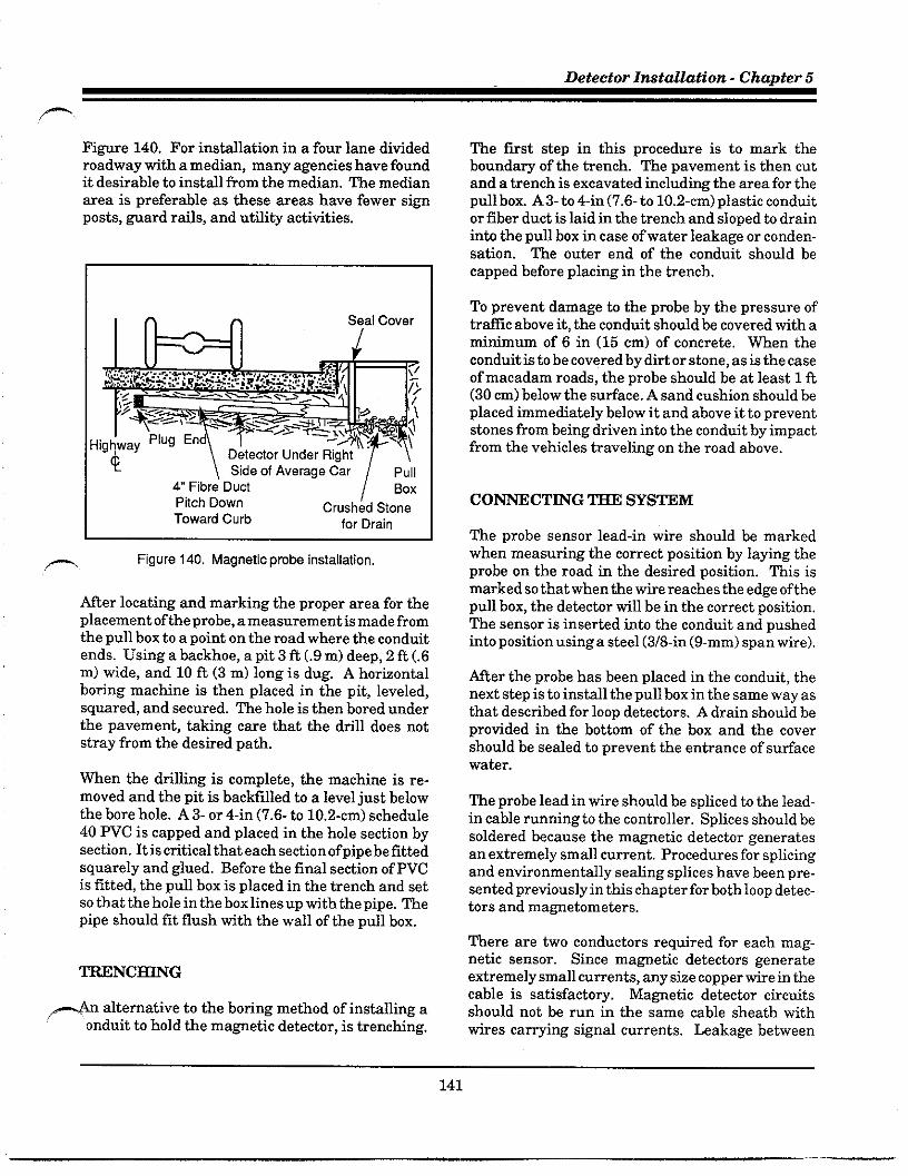
—
Detector InataZZation - Chapter 5
m
Fi@re 140. For instillation in a four lane dividedroadway tith a median, many agencies have foundit desirable to install from the median. The medianarea is preferable as these areas have fewer signposts, ward rails, and utflity activities.
Pitch Down Crush~d StoneToward Curb for Drain
Rgure 140, Magnetic probs installation,
After locating and marking the proper area for theplacement of the probe, a measurement is made fromthe pull box to a point on the road where the conduitends. Using a backhoe, a pit 3 ft (.9 m) deep, 2 ft (.6m) tide, and 10 ft (3 m) long is dug. A hortiontalboring machine is then placed in the pit, leveled,squared, and secured. The hole is then bored underthe pavement, Wing care that the drfil does notstray from the desired path.
men the drilling is complete, the machine is re-moved and the pit is backfilled to a level just belowthe bore hole. A 3- or 4-in (7.6- to 10.2-cm) schedule40 PVC is capped and placed in the hole section bysection. It is critical that each section ofpipe be fittedsquarely and glued. Before the final section of PVCis fitted, the pull box is placed in the trench and setso that the hole in the box lines up tith the pipe. Thepipe should fit flush with the wall of the pdl box.
~ alternative to the boring method of instilling aonduit to hold the ma~etic detector, is trenching.
The first step in this procedure is to mark theboundary of the trench. The pavement is then cutand a trench is excavated including the area for thepdl box. A3- to 4-in (7.6-to 10.2-cm) plastic conduitor fiber duct is laid in the trench and sloped to drnininto the pull box in case of water leakage or conden-sation. The outir end of the conduit shmdd becapped before placing in the trench.
To prevent damage b the probe by the pressure oftraffic above it, the conduit shodd be covered tith amitimum of 6 in (15 cm) of concrete. men theconduit is to be covered by dirt or stone, as is the caseof macadam roads, the probe should be at least 1 ft(30 cm) below the sutiace. A sand cushion should beplaced immediately below it and above it to preventstones from being driven into the conduit by impactfrom the vehicles traveling on the road above.
The probe sensor lead-in wire should be markedwhen measuring the comect position by laying theprobe on the road in the desired position. ~is ismarked so that when the wire reaches the edge of thepull box, the detector till be in the correct position.The sensor is inserted into the conduit and pushedinto position usinga steel (3/8-in (9-mm) span wire).
After the probe has been placed in the conduit, thenext step is to install the pull box in the same way asthat described for loop detectors. A drain should beprotided in the bottom of the box and the covershould be sealed to prevent the entrance of sufiacewater.
me probe lead in wire should be spliced to the lead-in cable running tothe controller. Splices should besoldered because the magnetic detector generatesan extremely small current. Procedures for splicingand environmentally sealing splices have been pre-sented preciously in this chapter for both loop detec-tors and maWetometers.
There are two conductors required for each mag-netic sensor. Since ma~etic detectors generateextremely small cuments, any size copper tire in thecable is satisfactoW. Ma@etic detector circtitsshould not be run in the same cable sheath withwires camying signal currents. Leakage between
141

Pafic Detector Handbook
wires camying signal currents. Leakage betweenthe signal tires and detector wires will cause ematicoperation of the detectors. Electromagnetic or elec-trostatic induction between siWal wires and detec-tor wires could cause false calls. However, anynumber of detector tires can be housed in the samecable sheath without causing intefierence.
Two tests should be conducted with a volt-ohmmeter during installation to detemine the seriesresistance (continuity) and wound resistance. Foreach probe in the series circuit, the series resistanceshould register 3800 ohms, plus or minus 10 percent.If there are two probes, the reading should be around7600 ohms, If the meter reads several times thenomal resistance, a check should be made of the
wiring and splicing, and each probe should be testedindividually.
Resistance to wound should measure severalmegohms. Low resistance indicates leakage throughthe wire insolation or the probe. Such leakage willnot prevent relay response unless it is suficient toreduce the probe output.
~enthe gain is set on the amplifier, it should be setat the lowest value possible to insure proper opera-tion. The reason for this is to avoid spurious detec-tion of vehicles in other lanes.
The test readings and gain settings should be re-corded on the construction plans and on forms whichare stored in the controller cabinet, as well as thosefiled in the maintenance office. This informationshould always be referred to when maintenance isrequired.
,—
142

.m.
6. DETECTOR WNTEN~CE
Most agencies responsible for traffic detector opera-tions readily a~ee that proper and adequate main-tenance is critical to effective traffic si~d controlsystems and surveillance and control systems.Central to this is the careful installation and the useof appropriate materials and products. However,even with both superior design and installation, thesystem will not operate as intended if the basicfundamentals of maintenance management are not
applied. Unfortunately, there are many factors thatimpede the best intentions.
Problems of inadequate budget and staffing defi-ciencies have a profound effect on the leve] andquality of maintenance activities. Budgetary prob-lems that continue to pla~e traffic agencies have
-resulted in cost-consciousness that frequently fo-cuses only on initial cost, rather than on lifetimecost. Consequently, less expensive products, mate-rials, antior processes are used in the original in-stallation because of their lower initial cost. How-ever, this is not always a cost-effective solution.
Wile budgetary/funding problems may not be eas-ily resolved, they may be ameliorated by increasedattention to cost-effectiveness in all phases of de-sign, installation, operation, and maintenance.Staffing problems, in terms of numbers and skilllevels of maintenance personnel, may be reducedsomewhat by selecting only the equipment that canbe realistically maintained by available personnel.
This chapter is addressed to those responsible forthe management of the maintenance operations aswell as to maintenance supervisors and technicians.Design engineers and those responsible forinstalla-tion and operations should be fully cognkant of thecause and effect relationship between their activi-ties and the maintenance problem,
Please nom that there are a number of excellentfieference sources addressing the maintenance proc-
SS. Recommended sources for futiher detiils con.
cerning comprehensive maintenance pro~ams in-clude ITEs Trafic Signal Installation and Mainte-nance Manual (Ref. 38), T~s Maintewnce Man-agement ofDafic Signal Equipment and Systems(Ref. 39), andF~Ks Tmffw Control Devties Hand-kaok (Ref. 40).
NAT~ OF THE PROBLEM
The nature of the problems associated with detec-tors has changed considerably over the years. Forexample, the detictor electronics unit, which for.merly accounted for a considerable potiion of detec-tor malfunctions, has pro~essed to the point wheremany currently avaflable digitd models seldomexperience faflure. As stressed continually thro~h-out this manual, proper installation using appropri-ate materials and processes is the key to longerdetector life, lower failure rates, and less reqtiredmaintenance.
There is little question that detector malfunctionsand the associated si~d failures increase motor-ists’ time and delay, maintenance costs, accidents,and liability. For example, a simple failure of adekctor loop can induce delay in the trfilc flow. Ifa call is locked in to the controller, it wfll cause the~een to extend b its maximum limit regardless oftraffic demand.
In cases where the detectir fails without a call, thecommon temporary Wx” is h place the phase onMafimum Recall in the controller. This can increaseintersection delay by 50 percent or more.
Mthough faflures cannot be totally eliminated,adherence to proper installation and maintenanceprocedures can assuredly reduce the incidence offailure and the number ofunnecessarymaintenancecalls. Some of the common causes of failure arediscussed below.
143

Traffic Detector Handbook
FAILURES IN LOOP DETECTORSYSTEMS
men a detector systim experiences a failure, itexerts a negative effect on the total trafic signalcontrol system. As discussed in Chapter 5, failurescan be categorized by the failure mechanism and bythe cause for failure.
F~= ~C~SMS
A failure mechanism maybe defined as the effect ofa problem occuming in the detector system. Amongthe common failure mechanisms, are the following:
Omitted Phase
The signal does not sertice one phase due to the lackof detector calls. This is usually caused by a 100Pfailure. Earlier detector units with solid state out-puts would fail in the “open” position resulting in nocall to the controller. Newer units have circtitrythat provides a continuous call if the loop circuit isincomplete. (See Phase Extending to Maximumbelow.)
Stuck Signal
A stuck signal is characterized by a signal indication(or phase) not changing as pro~ammed. In mostinstances, a stuck signal is not caused by the detec-tor system, but by a controller failure. On occasiOnit may be caused by a vehicle not being properlydetected, or when a detector unit, operating with thedelay feature, does not retain the call for a sufficientamount of time to be transmitted to the controller.
Phase Etiending to Maximum
This situation occurs when a specific phase of thesignal operation extends to the maximum time seton the controller regardless of trafic demand. Thisis typically caused by a continuous call from thedetector unit and can generate extra delays of up toone-half the normal daily delay. The continuous callmay be caused by a faulty detector unit or by an openloop circuit.
Intermittent Problems
Low sensitivity of the loop or the detector unit (orcombination ofboth) can result in intermittent prob-lems. Unstable oscillators in the detector unit mayalso cause intermittent problems during periods ofrapid temperature shifts. However, many of thecument detector units are capable ofretuning. menthe problem persists for no apparent reason (termed“ghost problems”), the detector unit is usually re-placed.
A broken loop wire that will ordinarily cause amalfunction may reconnect itself with shifts inpavement and cause intermittent operations. Theonly cure for this situation is to replace the loopwhen it has been determined hy a process ofelimina-tion that the only remaining problem could be abroken wire.
External detices, installed to provide additionallightning protection, may have been damaged by apower surge. This may result in intermittent Opera-tion. Since this damage may not be visible, these —.devices should be checked ifintemittent operationoccurs.
Crosstalk
Crosstalk is the result of inductive or capacitivecoupling between loops or lead-in tiring. Crosstalkmay produce false detections when there are novehicles in the detection zone, It may also result inlock-up following a vehicle detection. It is usuallyassociated with motion in either the generating orreceiting loop channels due to transient frequencyali~ment caused by a vehicle signal.
Crosstalk occurs when the frequency of one loopinstallation is influenced by the frequency of an-other. This nomally occurs when the frequency ofone loop system is decreasing and passes through ornear the frequency of the other loop. Electricalengineers refer to this as a “frequency loc~’ betweentwo oscillators.
This condition occurs only when the frequencies ofthe two oscillators are close and electronic coupling,,_exists between the two oscillators. There are numer-ous sources of electronic coupling. Some of the morecommon sources include:
144

Detector Maintenance - Chapter 6
.
.
.
.
.
.
Poor quality connections in the loopsystem.
Field coupling due to close physicalprotimity of two loops.
Coupling between two closely spacedlead-in wires.
Couplinghetween lead-in cables shar-ing a common condtit.
Groundtig of the lead-in cable shieldat controller cabinet field teminals.
CouDline between closelv suaced har-. .nes~wires from the field terminals tothe detector.
Sph&Over
The false detection of vehicles outside the zone ofdetection is termed “splashover?’ NIS problemofien ocmrs when long loops are operated at a levelof sensitivity required to detect small vehicles (i.e.motorcycles). With this high level of sensitivity,vehicles from a~acent lanes maybe falsely detected.This problem also occurs when the loop is placed tooclose to the lane line. Splashover is a problembetween lanes controlled by different phases. It isnot a problem between lanes on the same phaseunless accurate vehicle counts are desired.
CAUSES OF LOOP SYSTEM F~=
As discussed in Chapter 5 and detded in AppendixM. sumevs of traffic aeencies indicate that there are,.eight primary causes of loop failure:
● Pavement problems (crackingmoving).
● Breakdown of wire insulation.
and
● Poor sealants or inadequate sealantapplication.
● Inadeqwte splices or electrical con-nections.
.
.
.
.
Damage caused by construction ac-tivities.
Improper detector unit tuning.
Detector unit ftilure.
fighttin~electrical surges.
FACTO~ AFFEC~G NEEDED~NANCE
Many agencies report that most of their mainte-nance Droblems involving detectors can be traceddirectl~ to installation er~ors. These errors can be adirect result of sloppy installation, poor inspection,and the use of low-flade components not suited tothe particular environment.
Many agencies do not use their own forces to installdetectors. In these cases, the contract to instilldetectors is usually awarded to the lowest bidder.The “lowest bidder” concepthas been very successfulin encouraging competitive bidding and generallylowering costs. To be effective, however, a procuringagency needs to apply stringent prequdficationguidelines to avoid awarding the contract to anelectrical contractor with inadequate experience andor knowledge.
If inspection is inadequate, the potential for con-tractor expediency and error is enomous. The con-sequences of these improper shoti cuts or errors maynot sutiace until the contractor’s responsibility haselapsed and must therefore be repnired at the ex-pense of the agency. For example, piercing, cutting,or otherwise damaging the insulation on the loopwire by the use of improper tools or careless han-dlingmay not show up untfi some time after the tireis sealed in the slot.
In Chicago, the Illinois DOT maintains over 18,000loop detectors. Because oftheirpast experiencetithloop ftilure, they initiated an active inspection andmaintenance pro~am to monitor each loop. Thispro~am has reduced replacements to about 35 re-cuts per year. They report that no more than 5percent of their loops are inoperative at any giventime (Ref. 14).
145

~afic Detector Handbook
TRO~LE SHOOT~GPROCED~S FOR LOOPDETECTORS
The analysis of a malfunctioning detector can be adifficult task. The root cause of the failure maybeassociated with environmental conditions or otherconditions buflt into the installation. Ml of thevarious causes of failures defined above shodd beconsidered by the technician analyzing a faulty loopsystem. Initially, of course, it is necessa~ to isolatethe problem as one associated tith the detectorsystem.
An experienced technician is frequently able topinpoint the troubled area or fadty part by tisualexamination. As shown in Fi~re 141, it is readilyaPParent that pavement failure has occumed alongthe saw slot exposing the loop wires. When tisualinspection does not immediately disclose the prob-lem, systematic trouble shooting is reqtired. Proce-dures that may be applied in identifying and correct-ing malfunctioning detector systems are discussedbelow.
loop installation with exposed or shallow-buriedwires should be replaced,
If the sealant appears to be unstable, a blunt instru-ment may be used to remove any cracked or deterio-rating sealant. The slot shodd be blown clean withcompressed air and new sealant poured over the old.This is especially impotiant in areas when snowremovdequipment is used and sdt applications areprevalent.
Pot holes within the loop area should also be re-paired. Some agencies use a cold mix compound. Athin blanket overlay covering the area has provedeffective for patching deteriorating pavement. WAReports (Ref. 41 and 42) protide detailed instruc-tions for repairing pot holes.
As the loop wire is the mostvtinerable component inthe hostile environment of the street, a scheduledvisual inspection of the saw slots shodd be con-ducted every 6 months. Early detection and comec-tion of saw slot problems can avoid many potentialdetector malfunctions.
figure 141. Example of pavement failure.
SAWC~~TENANCE
Avisual inspection of the roadway at and around thesawcut should be made to determine if the inte~ityof the pavement, the sealant, or the slot has beenviolated. Theinspection should include looking forwires thathave floated tothetop of the sealant. A
~~GE~NT OF LOOPCO~CTIONS
When the loop does not have sufficient sensitivity todetect a vehicle, this usually means that the induc-tance is too low. This situation could be caused by aninsufficient number ofturns of wire, by turns of tireshorted together, or by steel mesh in the roadwaythat has produced a shorted-turn effect. If thisoccurs ina multiple loop confi~ration, it maybetemporarily comected by eliminating the defectiveloop.
Multiple loops can be connected in series or seriedparallel to maintain an equivalent inductance withintherange of the detector unit. Quantitative meas-urements are made to determine if the inductance ofa malfunctioning system has dropped below theacceptable value. There are several test meterscommercially available that till detemineinduc-tance. Some ofthesemeters directly measure induc-tance, while others measure frequency. In the lattercase, accompanying charts or ~aphs are used to —determine inductance.
146

—
Wetector Maintenance - Chapter 6
ELI~A~G ~OSST-
As defined earlier, crosstalk can resdt when twoloop lead-in cables share a common conduit, operateat close to the same frequencies, or the cable shieldsare not properly connectid. Crosstalk may alsooccur when two loops are instilled tithin a few feetof each other, or when two sets of lead-in wiresoccupy the same saw slot. Other causes include poorquality splices and coupling between closely spacedwires in the cabinet harness. Potential solutions tothese problems are listed below.
.
.
.
.
,- “
Poor quafity connections in the loopsystem Solutions include use of highquality soldered joints, solderingofdlcrimp connections, minimizing thenumber of j oints, use of high qualityconnectors and replacement if worn,safe~ards against comosion, tightterminal block screws, and twistingan soldefing ofwire ends together andplacingunderone temindblock screwrather than two individud screws.
Field coupling due to close physicalprofimity of two loops: Not much canbe done to eliminate this source.However, frequency separation antior use of a multichannel multiplexeddetector are effective solutions.
Coupling between two closely spacedlead-in tires: Solutions include inde-pendent routing in slots physicallyseparated by at least 1 ft (0.3 m),twisting loop tire pairs a mifimum of5 turns per foot (16.5 turns per meter),use of multichannel multiplexed de-techrs, and frequency separation.
Coupling between lead-in cables shar-ing a common conduit Solutions in-clude the use of inditidwl, shielded,twisted-pair cables; proper Woundingof cable shields; use of multichannelmultiplexed detector% and frequencyseparation.
Grounding the lead-in cable shield atcontroller cabinet field teminals: A
potential solution is the use of thethree teminal method (see fiWre132). This procedure is to strip theindividual lead-in cables back a maxi-mum of 2 to 3 in (5 to 8 cm) and groundeach lead-in cable independently.(Note: Until1990, the Ontario Minis-try of fiansport (Append&N, page g-36) specified that the shields shoddbe wounded at the pull box and not inthe cabinet.)
● Coupling between closely spaced h=-ness wires from the field teminals tothe detector The solution is to eitheruse shielded twistid cable with propergounding of the shield or use twistedwire pair.
One agency (California Depatiment of fiansporta-tion, Wf. 32) described a procedure for identifyingand comecting crosstalk. They used a modified looptester for the following four-step procedure.
Using the aufiia~ input to the tester,measure the operating frequency oftheloopdetectir suspected ofcrosstilk-ing.
If the operating frequencies of two ormore detectors are less than 2 ~zapati, and they share one or moreconduit runs, they are likely tocrosstalk. This can usurdly be cor-rected by wounding the cable shieldsat the controller cabinet.
If the amplifiers have a range switchor other means of selecting frequen-cies, adjust so that operating frequen-cies are separated by at least 2 or morekHz.
If adjustments cannot be made, add-ing parallel capacitors to the fieldterminals may shlfi the operatingfrequencies. A quality capacitor suchas a polycarbonate or ceramic capaci-tor may be used. It shodd have areasonable temperature stabflity co-efficient and should be of a size ade-
147
Traffic Detector Handbook
quate to shift the resonant frequencyby about 2 kHz. This procedure can-not be used on detectors where theoperating frequency is independent ofloop inductance. Some manufactur-ers recommend against added capaci-tance extirnal to the detector unitbecause temperature stable capacitorsare dificult to procure and are stillprone to value change with rapidtemperature shlfis.
If the loop sensors are causing the crosstalk prob-lem, they can be reassigned to different channels, orthe lead-in wires in the pull box can be retwisted andrespliced, thus eliminating one form of potentialcrosstalk.
A general procedure to identify which detector unitis cross-talking consists of disconnecting all detec-tors except the units which have the most frequentfalse calls. If no new false calls or lock-ups occur,then crosstalk from another unit is indicated. Byselectively reconnecting the other units, the unitcausing the crosstalk between detectors can be iden-tified.
Certain of the multichannel detectors have a scan-ningfeature that reduces potential crosstalk effects.In these units, the sequential scanning system acti-vates one loop channel at a time, while the remain-ing loops, connected to other channels, are de-ener-gized and thus unable to provide coupling to theactive channel. This does not, however, eliminatecrosstalk between channels on different detectorunits. Frequency separation will reduce crosstalkbetween adjacent loops as well as with other detec-tors.
S~STITUTION OF DETRCTOR UNITS
Experience shows that older detector units could notbe freely substituted for each other. After conduct-ing tests in Los Angeles (Ref. 43) it was found that“., there are some brands of detectors that appear., .tohave more sensitivity than others.., Certain brandsan~or types will not operate tith adverse condi-tions such as very low circuit Q or a low value ofshunt resistance to the conduit ground.” It was
concluded that the inductance value at the cabinetend of the loop system must fall tithinthe operatingrange of the units if they are to be interchanged.With the newer products, units with the same char-acteristics and quality can generally be interchangedwithout problem, That is, different manufacturedunits operate on different frequencies; however, anyunit which passes the NEMA tests can usually beinterchanged.
Each unit within an agency’s inventory should bechecked for sensitivity to ensure that minimumsensitivity is achieved by all detector units, Mterthis check has been made, the substitution processcan be used to detemine if the detector unit at themalfunctioning installation is the cause of the fail.ure. That is, if the detector unit is replaced and thesystem functions normally, this may indicate a fail-ure in the detector unit. Conversely, if the loopsystem still does not operate better with the substi-tuted unit, then the original detector unit is rein-serted and another problem source must be soughtto resolve the problem.
In substituting detector units, it should be recog- “-nized that many malfunctions are crosstalk related.Hence, any change that will affect the loop frequencywill improve the situation, at least temporarily,
Substitution of another detector, even of the samemodel and frequency setting, wfll often work welldue to the subtle differences in the values of thedetector input capacitors. Substitution ofa differentmodel (especially ofa different manufacturer) standsa good chance of being successful due to differencesin front end desi~, The best solution is to eliminate,to the maximum practical extent, those elementsthat contribute to crosstalk.
OPERATION~ CHECK OFWFUNCTION~GDE~CTOR
There are several operational checks that can beconducted to expedite the analysis ofa malfunction-ing detector system. These checks can be accom-plished using a maintenance vehicle and a vehiclesimulator. With this equipment, tests can be per-formed to analyze adjacent lane detection, motion inthe loop wire, intermittent detection, and sensitivity -of the loop system.
148

Detector Maintenance - Chapter 6
—
Adjacent Lme Detection
At locations where adjacent lane detection is sus-pected (such as where long loops are used onleftturnlanes), one technique is to maneuver the mainte-nance vehicle close h the lane and monitor thedetector utit. The sensitivity is then adjusted sothat the maintenance veficle does not cause anoutput. Care must be exercised to assure that thedetector ufit wfll still register a small vehicle in thedetection zone.
It should be noted that this procedure does not testthe worst case. The worst case is when severalvehicles are stopped in the adjacent lane and occupythe entire length of the long loop.
There are several loop configurations that can beused to avoid adjacent lane detection (i.e., series ofsmall loops, quadruple loops, atiustable diamondloops, and others as described in Chapter 4). Whenit is not possible to change loop configurations, delaytiming can be used so that a vehicle would only bedetected ifit were present in the detection zone fora specified amount of time (say, 5 seconds). Withthis approach, passing vehicles in an adjacent lanewmdd not be detected, although stopped vehiclesmay present a signal strong enough to hold the callin the empty lane.
Intermittent Operation
The beginning ofloop fafiure is often associated withintermittent operation. As discussed earlier, causesof this type of operation are generally poor connec-tions, open loops, short circuits, orleakagestogmund.~ese, in turn, may cause the detector to lock-upwhen a motor vehicle passes over the point of thefadt.
To identify this problem, the operation of the detec-tor is observed whfle the maintenance vehicle isdfiven over the various loops suspected of havingintermittent operation. Operation of the vehicle inthe detection area can also assist in identifyingproblems associated with wire motion. Anotherapproach to identifying sources of intermittentoperation is to tisually inspect all connections andtest with a 500 volt megger and a low ohm midscaleohmmeter.
System Sensitivity
A device to simulate vehicles can be used to deter-mine if the detector system’s sensitivity is in ba-lance. The same procedure is used to test newinstallations. The State of California uses a shotied-turn vehicle model h simtiate a 100 cc Hondamotorcycle. Ref. 32 provides the construction detaflsand their procedures for using this model.
The simulated vehicle is used to measure the changein inductance, which is a measure of the sensitivity.For this purpose, a frequency reading is made tithno vehicle present, then the simdated vehicle isintroduced into the detection area and a new fre-quency reading is made.
me difference between the two frequencies is ameasure of the change in inductance due to thepresence of the vehicle according to the relationshipof Aflf = U2 AUL. This is an approximate relation-ship valid for percentage changes in inductance upto 10 percent and for loop Q ~eatsr than 5. Thepercent change infrequency is mdtiplied by 2 to getthe percent change in inductance.
The simulated vehicle represents the smallest de-tectable vehicle and is dso used to determine themitimum sensitivity required of a loop system. Thesimulator is placed in the detiction zone and thedetector unit is obsemed to determine if it is de-ticted.
ELEC~CAL TESTS OF DETECTORSYS~M
Table 28 identifies some of the probable causes forspecflc malfunctions. The maintenance of properresistance values and knowledge of inductance va-lues for proper hookup to detector units til elimi-nate many of the problems associated with 100Poperation. Basically, four detices are desirable toanalyze loop systems. A high voltage resistancetester (megger), used to measure insulatkm resis-tance; a frequency tester (see Figure 142) or induc-tance meter, used b measure inductance; a digitdvolt-ohm meter, used to measure series resistance;and a low ohm (about 2 h 3 ohms) midscale ohmme-ter, used to measure the dynamic change in theseries resistance.
149

~afic Detector Handbook
—
Hgure 142. Typical frequency tester,
Both low resistance-to-gound and high series resis-tance are major factors in loop systim malfunctions.Low resistance-to-ground can result from poor insu-
lation on the loop or lead-in wire, or inadequatesealing of splices. These problems should not occurif, during installation, proper care was taken inhanding the matetials and following appropriatesplice sealing methods. Low resistance-to-floundcan also occur when wires are exposed as a result ofpavement cracking, sealant cracking, frost action,and from studded tires wearing down pavement. Inaddition, excess wire coiled in the pull box or control-ler cabinet can add inductance to the circuit. Thismay result in tuning problems. There is also anincreased potential for coupling to another loopsystem.
High series resistance can be caused by poor splices,comoded or loose screw terminals, poor crimping, orinadequate wire size, The high series resistanceproblem is sensitive to humidity, temperature, andvibration, which will cause drifting and false calls.These are the same problems that occur when thesystem has low resistance-to-wound.
~ST PROCED=S —.
To isolate the causes of erratic operation or systemmalfunction in a detector system, the tests from Ref.43 presented below should be pefiormed sequen-tially.
Table 28. Loop malfunctions andposaiblecauses
Malfunction
Possible Cause No Call Constant False Call Dfifting Crosstalk Wll Not UnbalancedCall Tune Sensitivity
Low Q IlxllllxlxlLow Resistance to x x x x x
Ground
High Series Resistance 11X1X X11X1X1Improper Inductance 1X1X111 1X1X1
Poor Ground II 1X11X111Improper Installation Xlxlxx xll xl-
Detector Malfunction ~ X I X I X ~ XlX,l
150

Detector Maintenance - Chapter 6
Equipment Wquired
~ese tests reqtire the following eqtipment
.
.
.
.
.
.
.
Ohmmeter, battery operated.
AC Voltmeter, high impedance inputb 100Mz.
Digital Frequency Counter, inputimpedance >50 K to 200 K
Q Test Meter.
Loop Tester Meter.
Datu Recording Fores for Q and Sen-sitivity (see Fiwres 144 and 145).
Vehicle Simtiator, Sensitivity Stan-dard.
In cases where pavement overlays have covered theloop instigation, a loop finder such as that shown inFl~re 143 can be used to identify the location of theloop.
Sequential Test Pmcedme
The following tests, when perfomed sequentially,should isolate the causes for a detector system be-coming inoperative or experiencing ematic Opera-tion. The Quality (Q) data form is illustrated inFignre 144. The Sensitivity (S) dati form is por-trayed in Fi@re 145.
Step 1. VisuaZ ZnspectiOn
Check for indication of broken or cut loop or lead-inwires. Check for open leads within the controllerand for the availability of power to the detector.
Step 2. Check Detector Unit
To mle out the detector unit as the source of theproblem, replace the etisting detector unit with onehaving a known sensitivity. If the operation is notconsiderably improved, remove the substituted uuit,replace the original utit and continue h Step 3.
Hgure 143. Loop finder.
(One manufacturer notes that since many problemsare crosstalk-related, any change that wfll fiect theloop frequency wfll improve the situation, at leasttemporarily. Substitution ofa detector unit, even ofthe same model and frequency stitch settings, wfllfrequently work successfully due to subtle dfierencein the values of detector input capacitors. Substitu-tion of different models (especially from differentmanufacturers) will have an even greater chance ofsuccess because of the difference in front-end deei~.Therefore, substitution of detector units may solvethe problem temporatiy but, in actwlity, the realproblem has not been resolved. If the problem iscrosstalk-related, the most effective solutlon is toidentify and eliminate the causes of the crosstalk.)
Step 3. Memure Q Fmtor
Measure and record the following data on the Qual-ity (Q) data form (Fi@re 144).
151

Trafic Detector Handbook
QUALITY (Q)
Location: Date:
Description: By:
Position Connec-E Ips ‘LT
tion (~h) ITf, f~ f, B~ Q Rp Remarkstalc.
‘rr — — —
‘l—l—r — — ‘l—r —‘rrr - — ‘—- —‘l—r— — — —‘r — — — — —
Analysis:
E ,P, = voltage across loops; fLT = frequency of Loop Test Unit; f,, fh, fl = frequency for resonance, high, low;
Bandwidth (Bw) = (f ~ f,); Q calculated = (f, / Bw); RP = resistance to ground.
.—
figure 144. Quahty (Q) data form
152

Detector Maintenance - Chapter 6
SENSITIVITY (S) I
-ocation:
description:
Loop ! Sensitivity I FrequencY(kHz) I Se:;y
Position Standard
J ? t ,;
. —.—
‘rlr __
IE ,—!_!
LLLL
l_l_LLLLLL — —— — —. — —L — —L
Analysis:
Presence
Minutes
Date:
By;
!Remarks
f, = resonant or tuning frequency; f2 = loop frequency with test standard or vehicle;
s = [(f22 f ~? / f2?’ 100s thechan9ein inductanceinpercent
Figure 145. Sensitivity (S) data form.
153
fiaffic Detector Handbook
● With the detictor disconnected andpower removed from the loop, meas-ure the resistance from either loopterminal to the bus or conduit ~ound.Record as ~ ti the Q &ti fem. Checkfor series continuity between the ter-minals.
c With the Loop Test Meter attached tothe controller tie points and the detec-tor disconnected, measure the induc-tance of the loop system’. Record thefrequency (f.,) and the inductance (L)on the form.
Step 4. Determine Q
To determine the Q Factor of the loop system, followthe procedure described below and record the re-sults on the Quality (Q) form (FiWre 144):
c Attach the Q Test Unit h the efistingcable or adaptor cable as reqtired.
● Connect the AC voltmeter and digitifrequency counter to the Q Test Unitto read loop voltage and frequency inkHz.
● Adjust the frequency for maximumvoltige across the loops; record thefrequency as(f) and the voltage acrossthe loops as (El,].
● Adjust the fiequencyhigher and lowerh obtain the frequency points hating70 percent of the resonant voltagevalue. Record theee as higher (f~) andlower (f,).
● Calcdate and record the bandwidth(Bw) and compute Q. That is, Bw = f,-~ and Q= frl Bw.
Step 5. Measure Sensitivity ofLoop System
Record the frequencies obtained from either of thefollowing methods on the Sensitivity (S) data fom(Fi@re 145).
Method 1
.
.
.
.
.
.
Set the function stitch to “Q ~Non the Q Test Unit.
Adjust the frequency to obtain reso-nance and record as (f,).
Record the reference number of theSensitivity Standard to be used.
Place the eimulator or vehicle on thedesired loop.
Retune the frequency of the detsctorto the new resonant point and recordas (fz).
Calctiate the sensitivity as indicatedon the data form.
Method 2
.
.
.
.
.
.
Set the function switch b “INTER- .—.NAL” and the mode switch to ‘lS>>onthe Q Test Unit.
Mlow the detector to tune downwardin frequency to the “lock-on” point.
Note the frequency and record as (f,)on the form.
Place the Sensitivity Standard on thedesired loop.
Note the new lock-on point frequency.Record as (f,) on the fem.
Calcdati the sensitivity as indicatedon the data form.
Step 6. Analysis
Conduct the analysis by comparing the values ob-tainedfor each of the system characteristics with theacceptable limits listid in the Loop fiouble ShootingChart (see Table 29). Determine the required main- _,,,tenance from the suggested comective actions fromthe form.
154

Detector Maintenance - Chupter 6
n
Table 29. Loop trouble shooting chart.
Item
Loop wires
Loop slots
Resistance toground
Series LoopResistance
Q Factor
Sensitivity of LoopSystem
Sensitivity ofdetector
Indcated Conditions
Broken, cut, or exposed
Insulation worn away
Sealant missing
Wre exposed
Surface eroded
100 MQ or more
Shorted
Open circuit
Greater than specified (basedon wire size and length)
>5, Rp >100 M
<5, any ~
Measures lower than designvalue for the configuration
Does not actuate
Insufficient sensitivity
Corrective Action
Install new loops shifted by 6 in (15 cm) from the oldloop and cut each old loop at least twice
Clean slot of loose material and refill or replace entireloop and lead-in as required above
Street surface patch if loop wire is not exwsedI
Acceptable if Q >5
Replace as required
Locate and correct open circuit IIsolate cause (poor splice, inadequate crimp, etc.)and repair as required !
Acceptable with modern detector units
Re~lace detector unit 1I
Consider Q, shunt Rp, and sefies R as possiblecauses and correct as indicated
Determine loop interconnection and rework toaccepted design values
Substitute known serviceable detector
Substitute known serviceable detector
Substitute and return unit removed to shop. .
The limits placed on the characteristics are nominals determined trom tne ongmal mvesogaIlorr. They mayrequire modification to reflect additional experience.
WTEN~CE OFMAGNETOMETER SYSTEMS
Themagnetometer detector system is made up of theprobe, probe cable, lead-in cable, and the detectorelectronic unit. The same precautions should beobsemed for the probe cable and lead-in @ome run)cable as for the loop lead-in wire and lead-in cabls.
The probe cable is placed in a slot in the road sufiaceand should be sealed with the same care as for loopdetector lead-ins. The splices connecting the probecable and the lead-in cable must be mechanicallyand electrically sound and environmentally pro-tected as described in Chapter 5.
n, Failure can occur in any of the subsystems. me
-. principal causes of ma~etometer failures are de-..,, - scribed below.
CAUSES OF WG~TO~~R F~~S
Thereare four key areas that can tiect the opera-tion of the ma~etometer detector system. Theseare: proper bwial depth of the probe, stabflity of theprobe in the pavement, characteristics of the probecable with regard to moisture penetration, and sawslot maintenance.
Probe Burisd Depth
The vertical placement of the probe is critical tosystem performance. Deep placement of approxi-mately 24 in (60 cm) wfll provide good single countdetection, but will resdt in lower signal levels. Shal-low placement of about 6 in (15 cm) wfil provide astronger signal, but there is a greater potential fordouble counting. ~erefore, the burial depth must
155

,
Traflc Detector Handbook
—
be appropriate for the intended application as de-scribed in Chapters 4 and 5.
Probe Movement
The probes must be firmly suppotied in their holes.Any displacement of the vertical ali~ment of theprobes may result in pefiormance instabdity. PVCconduit as a shell, with sand tamped around theprobe to prevent lateral displacement, is recom-mended.
Probe Cable
The cable must be water-blocked cable to preventmoisture penetration. &y moisture can cause ex-cessive capacitance or leakage between wires or taground. In addition, moisture across the leads of amagnetometer may induce drift. Wherever pos-sible, it is recommended that the probe cable mndirectly to the detector unit, thus eliminating theuse of splices. If this is not possible, the splices mustbe electrically sound and environmentally proticted.
Sawcut Maintenance
Thesawmt for the ma~etometer should be visuallyinspected every 6 months to evaluate the conditionof the sealant and the sumounding roadway. Aswith the loop detector sawcut, any cracking or dete-riorating sealant shodd be chipped away, blownclean, and replaced with new sealant.
TRO~LE SHOO~G PROCED~S
The initial step for troubleshooting problems withthe magnetometer system is to visually inspect allelements of the sysbm, including the connections atthe terminal strip in the controller cabinet, anysplices in pull boxes, and the street installation ofthe probe and probe cable. These elements should beexamined to detect any loose connections, poor sea-lant, exposed wires, bad splices, or evidence of recentconstruction.
If none of these, elements show any evidence ofproblems, the next step is to examine the probe for
tilting. Without retuning the detector unit, use thebar ma~et oriented in a direction which aids thevertical component of the eatih’s ma~etic fieldintensity (as descfibed in Chapter 5) to measure thedistance from the road sufiace that wfll cause thedetection to occur. Compare this measurement withthe one taken at the time of installation.
Ifthe distance is smaller than the original measure-ment, then the probe may have tilted due to pave-ment movement. Ifthe probe hastiltid, the detectorunit maybe retuned and this location mOfitOred fre.quently for evidence of futiher tilting. If the unitcannot be retuned, the probe should be palled andreinstalled in the proper vertical alignment,
One way to compensate for the tflting problem is touse a Digital Nulling Loop such as that developed forthe City of Baltimore (Mf, 44). This detice has anautomatic compensating circuitry which is incorpo-rated into the detector unit. It works like a loopdetector in tracking environmental changes. One ofthese detices is required for each channel in thedetector unit.
If detection does not occur during the test for tilting,the problem cmdd be in the cable, tire, probe, splice,or detector unit. Series resistance and resistance-ti-gmund measurements should then be made at thecontroller cabinet with a volt-ohmmeter. The seriesresistance should be within 10 percent of the mess.urements made at installation, and the other read-ings should be high, indicating no breaks in theinsulation or in the intefity of the environmentalsplice.
Ifthe measurements do not fdl within these ranges,the next step is to determine whether the problemlies: in the probe, the probe cable, the splice, or thelead-in cable.
The splice should be taken apati and the followingtests conducted. A series resistance and resistance-ti-~ound measurement toward the probe should bemade and compared with measurements takenduring instigation. La~evariations indicate fatityprobe or probe cable. The best solution is h replacethe probe and probe cable,
On the other hand, if the measured values compare —‘favorably with the original values, the top pairofthe
156

-.>,.,.,....
Detector Maintenance - Chapter 6
lead-in cable wires shodd be tied together and thevolt ohmmeter read. ~is should be repeated withthe bottom two wires. If these values are high, thismeans that the lead-in cable should be replaced. Ifnot, the problem undoubted originates in the spliceand a careful reconnection of the sphce shodd elimi-nate the problem.
If this systematic method is used, the problem willusually be identified. me ori@nal reference sheetshould always be referred to during this process tocompare measurements. men the problem hasbeen rect~led, new values should be noted andretained for future reference.
WGNETIC DETECTOR~ENNCE
Magnetic detectors have an extremely good mainte-nance record. As they are installed under the roadsufiace, and all lead-in wires are in the fom of cableencased in conduit underground, the oppotiunity forfailure is relatively small. User surveys indicatethat these detectors do not present any major main-tenance problems, and that some of these deviceshave been installed for more than 20 years withouta fafiure.
In the rare case where a ma~etic detector fafis, thefirst step is to examine the amplifier. In cases of afalse response (the amplifier output relay closeswhen no cars are crossing the detection area), re-place the existing unit tith another tested unit,tune, and monitor. If the system then works, it canbe assumed that the original amplifier was at fault.If the system still does not work, a series resistancetest and then a resistance-to-wound test should bepetiomed. ~is should identify any leakage in thesystem.
me total detector circuit resistance to ground shouldbe measured afir disconnecting all of the jumpersto wound and the leads to the relay. In cases whereleakage is between detectircables and signal cables,a 1 megohm leakage may result in ematic operation.~is can be avoided by proper cable layout and goodsplicing. Occasionally, one probe circuit will pick upmore disturbance than another probe circuit on the
same phase. If this is the case, interchange probesat the teminal strip so that the probe circuit pickingup the most disturbance is at the “MaWetic DetectorMinus” side of the system.
If the voltmeter needle is jumpy when there are novehicles passing the probes, it generally indicatessurges in nearby power wires. If the probe can belocated closer to the traffic, the sensitivity of theamplfier can be turned down and the power lineswfll have less effect. By changing the orientation ofthe detector mis, the effect of a particular power finecan be eliminated or reduced significantly. Forminimum disturbance, the detector axis shodd beparallel to the power lines.
me relay unit is desi~ed to be immune to all linevolhge changes except for very violent ones. If it issuspected that the line voltage changes are causingthe voltmeter needle to jump, disconnect the “Mag-netic Detector Plus” and the “Magnetic DetectorMinus” leads and short them together. Ifthe voltme-ter needle is still jumpy, the trouble is due to linevoltage changes. In this case, examine the joints inthe power semice to make sure they are properlysoldered and insulated. If there are no obviousproblems, request the power company to check there~lation of the power supply and make the neces-sary changes in their equipment.
If the voltme~r needle tends to jump only when thesiWals change (tith the magnetic detector termi-nals short circuited), the trouble is insufficient cur-rent-camying capacity in the service wires betweenthe cabinet and power source.
If the voltmeter needle stays steady when the ampli-fier operates (with the detector leads shofied) andtends to jump when the si~d lights change (withthe detectors reconnected), the difficulty is causedby electromagnetic or electrostatic induction be-tween the wires camying signal wrrents and thewires leading to the maWetic detectors. Make surethat the condensers are in place across the teminalsto which the ma~etic detectors are connected, asthese condensers tend to absorb such surges.
Intermittent response might also be caused by theneutral fluctuating with respect to wound. ~is canbe stabiltied by making a connection to a dtivenround ground rod (that is required in mOst mOdern
157
Trafic Detector Handbook
—
installations). If the connections are stable, check included in the condtit tith the power supply leads.for leakage in the detector circuit by making the Induced voltage can cause false responses. Conse-same tests that were described above with a volt- quently, the lead-in cable should not be included inohm meter. conduit with other signal wiring, bother cause of
false response occurs when the gain is set too high.Other problems could involve induced voltage re- An adjustment of the gain on the amplifier willsponse, which can occur when the detector leads are generally solve this problem.
—
158

7. E~RGING TECHNOLOGY
Urban tr~lc congestion is one of the major prob-lems reqtiring immediate action in the 1990’s. Onthe U.S. freeways alone, congestion increased by 54to 68 percent between 1983-85. Traffic volumes areexpected to continue to increase by as much as 45percent by the year 2005. A reduction in the level ofcongestion wodd yield truly impressive savings interms of fuel, travel time, and accidents.
To tackle the problem, the U. S., European coun-tries, Australia, and Japan are all investing in hightechnology solutions for hardware and softwaredevelopment involving a coalition of government,university, and private industry. One of the mostpromising concepts for alleviating urban trfilccongestion is effective trafic surveillance and con-trol.
This chapter reviews emerging technology as itrelates to the detector requirements of intersectioncontrol and trtilc sumefllance and control systems.The new technolo~ includes new concepts, newproducts, new applications, and new procedures.Some of the products are already in use in selectsdlocations but have not, as yet, been applied fully,while others are still in the research and develop-ment phase.
DETECTOR DEWCES WERDEWLOPMENT
h the United States, the quest for a reliable vehicledetector that can be installed and maintained with-out disrupting traffic, whfie providing trtilc data atleast as accurate as the loop detectir, is continuing.The following section summaries the major ongo-ing developments.
The Self-Powered Vehicle Detector (SPVD)has beenunder development by the Federd Highway Ad-ministration since 1973. Basically, this system
consists of a cylindrical in-road sensor containing atransducer, a ~ transmitter with antennas, and abattery. The in-road sensor operates on the sameprinciple as the magnetometer sensor. It is poweredby an internal battery and its connection to the relayis a radio link. The roadside receiver includes acommercially available FM receiver and a tonedecoder electronics package. No lead-in or intercon-necting cables are needed. The concept is illustratedin Fi@re 146.
Tke SPVD can measure vehicle passage, presence,count, and occupancy. Speed measurements arepossible using two SP~s set a predetermined dis-tance apart.
Development =story
me SP~s transducer ititially consisted of twosingle-axis flmgati magnetometers. These werereplaced with a single, dual-mis “Brown” magne-tometer oriented to detect changes in the hotiontdand vertical components of the Earth’s ma~eticfield. A vehicle passing or stopping over the detectordisturbs both of these components, changing theoperating level of the magnetometers core. Thischange induces a voltige that enables the ~ trans-mitter, which sends two 30-ms tone-coded pdses,indicating the entrance and exit of the vehicle. (SeeRef. 45.)
The RF telemetry link was redesigned in 1978 byFHWA and the Naval Surface Weapons Center(NSWC). NSWC was contrac~dti develop 20proh-type systsms. Three of these units were tested bythe City of Kettering, Ohio during the period 1978 to1979 (Ref. 46). ho of the ufits were inst~led at aline-of-sight distance 500 fi (150 m) from their re-ceiver antennas. These two utits failed to functioneven when varying distinces were used. Electronicmalfunctions were suspectid.
The third unit was installed in a left-turn lane 118ft (35.4 m) from the receiver antenna. This unitoperated flawlessly during the year long test period
159
.*—

fiaffic Detector Handbook
)
/
Radio Transmissic nSignals VehiclePresence
,“,’
,’,’SPVD ReceivingAntennaAlternatives
CatinetAlternatives
,----
)--~O SPVD
ControlUnit
//////) 2/////
Fgure 146. Self-powered vehicle detector concept
160
.—
---

Ewrging Technology - Chapter 7
n
despite temperatures sometimes approaching O ‘F.~is unit was located 10 R (3 m) from the stop line inthe center ofa 6- x 6-ft(l.6- x 1.8-m) 100POperated fOrcomparative purposes.
Volumes from the SPVD prototype and the installedloop detector were extremely simfiar over the 1 yeartest period, except that the SPVD yielded highervolumes during congested petiods because its zoneof ifluence protided separate counts for closelyfollowing vehicles. The City concluded that theconcept was cost effective and wotiy of furtherdevelopment.
Mthoughthe lack oflead-in orinterconnectingcablesreduced the installation cost and traffic dismptionassociated tith loop detectors, the spectiled l-yearbattery life was considered a drawback. Accord-ingly, batteries have since been developed with a 2-year life.
Cwent Status
Development has been on-going and, in 1987, theF~A contracted to develop nine production mod-els uti~iing small-scale inte~ated circuit designs,and nine systems utiltiing large-scale inte~atedcircuit desi~s. Fi~re 147 portrays the SPVDsystem under development.
~ese production models are scheduled for accep-tance testing duringthe period 1990-91. They till bedesi~ed to transmit at least 500 ft (150 m).
Hgure 147. Self-powered vehicle detector.
~E ~A DE~C~ON SYS~M (WADS)
In freeway Sumefilance and Control Systems, adetector system is needed that can provide vehicledetection, auhmatic sumefilance, and the extrac-tion of data (volume, speed, occupancy, etc.) neces-sary for advanced control strategies in real-time. Asalgorithms become more complex, the need for moreaccwate data is critical.
With existing loop detector technology, the detectorprocessing algorithms must extrapolate the receiveddata to derive the reqtired tr~lc flow statistics.These extrapolations can resdt in critical emorswhich contribute to unreliable incident detection.
Video cameras have been used for roadway sumefl-lance for many years. However, these camerasrequired a human operator to interpret the imagesgenerated. An alternative technique for interpret-ing the video images is through image processing or“machine vision.” This technique uses a computerand software to analyze the roadway images andextract the information needed for traffic sumeil-lance and control.
Evolution of WADS
The use of tideo technology and image processingtechniques that could be used as a substitute for loopdetectors was first investigated during the mid-1970’s (Ref. 47). This work initially was promotedand funded by tie Federd Highway Administra-tion.
The purpose of this initial project was to combine thetelevision camera with tideo processing technologyto identify and track vehicles traveling within thecamera’s field of tiew. The initial system was oflimited success because of the dfilculties with con-tinuously tracking a vehicle through varying back-~ound and lighting conditions.
During the 1970’s and 1980’s parallel effotis wereundertaken in Japan, the United Mngdom, Ger-many, Sweden, and France. The purpose of theseactivities was to address the problems and limita-tions of existing roadway detectors and fdfill therequirements of modern control technology forimproved detection, Atypical WADS set-up is showin Fi~re 148.
161

fiafic Detector Handbook
—
---—— — --- --- -------~
\
------
\ ‘-- ‘-- ‘--“--k ---=AB” CDEF
OpticalVideo Disk Raw
Video Display
@
‘o
VCR DigitizedVideo Display
WdeoCamera
Mdeo Data
J
.,Input,,
Monochrome
VideoTape
11111McrEOmputer
~
W-..L----my-a,”
Real-TreeDigital
Recorder
Hgure 148. Wde area detection system
—.
162

Emerging Technology - Chapter 7
A
Videoflmge Processing Systems
As a follow-on to the initial F~A WADS researchproject, a subsequent system was develOped by Dr.Panes Michalopoulos at the University of Minnesota(Ref. 48). This system, known as VIDS (VideoDetection System) was designed to use a single tideocamera with associated processing hardware andsoftware to provide outputs equivalent to those ofmdtiple loop detectors. This joint project was fundedby the F~A, the Minnesota DOT, and the Univer-sity of Minnesota.
or on siWd systems with central control capabilitytransmit their images to a central location for proc-essing. Cameras sewing isolated signalized inter-sections transmit their images to local processinghardwarein the control cabinet (Or in a separa~cabinet) installed at the intersection.
The system can detect trfilc at a number of loca-tions (multiple spots) tithin the camera’s field oftision. These locations are specified by the user withinteractive Waphics and can be changed as often asdesired. To achieve this flexible detection pointDlacement. detection lines along or across the road-
The operation of this real-time video ima~ng detec- -way lanes (as depicted in the trafic scene appearingtion system is depicted in Fi~re 149. Video cameras on the TVmonitor screen) are inserted on the screenare installed at selected locations on the freeway by means of a mouse or keyboard. Every time a
antior signalized intersections to collect trafic data vehicle crosses a detection line, a detection signal isin real time. Cameras installed on freeway systems generated.
~ power Supply /&~ooo
.“0”
Ke padltisplay(~alibration)
,-,
163
Hgure 149. Wide area video imaging system

fiaffic Detector Handbook
The processing system provides outputs comparableto loop detectors; that is, presence and passage aswell as speed. From these measurements, othertraffic parameters can he extracted, including occu-pancy, volumes, queue lengths, etc. The output ofthe system can be connected to an etisting controlsystem (either freeway or signal control) or to a localsignal controller where the detected trafic ~il] beprocessed by the traffic control application software.The advantage is that, in addition to wireless detec-tion, a single camera can replace many loops, therebyproviding true wide area detection.
WDS Development Status
A real-time version ofVIDS has been developed andsuccessfully demonstrated for a variety of roadway,environmental, and traffic conditions (Ref. 49). Thealgorithms have been developed h generati pres-ence and passage detection si~als and vehicle speedestimates for multiple detection spots in the camerafield-of-view. The first step in the algorithm ap-proach is to reduce the image data (from the videodigitizer) so that only the data needed for detectionis processed by the microprocessor, thus reducingthe amount of data to be processed by two to threeorders of ma~itude.
The data reduction or “image fomattin< is done inhardware to allow the algorithms to be done in real-time. This data reduction hardware is implementedon a single circuit card in the microprocessor calledthe fomatter. Once the data are reduced by theformatter hardware, spatial and temporal featuresare extracted for each detection location. Thesespatial and temporal elements are combined usingsequential decision processing to generate eitherpresence or passage si~als. Speed is estimated byusing pairs of closely spaced detection lines and thenmeasuring the time between adjacent passage sig-nals for these detection spots. This is very similar inconcept to speed traps used with loop detectors.
The algorithms have been optimized to deal withartifacts such as shadows, illumination changes,and reflections. The resulting system has producedvehicle detection accuracy in exc6ss of95 percent forall of the conditions studied. The conditions thatdegraded the performance in earlier video detectionsystems appear to be resolved. These include con.gestion, shadows, poor lighting, and adverse weather.
Mthough this is still a new and experimental ap-proach to traffic sumeillance, using advanced imageprocessing techniques, research and developmentare continuing and demonstration projects are ongo-ing.
~CROWA~U~DE~CTO~
The use ofmicrowaveradar during World War II ledto the use of this technique for detecting traffic.Microwave energy is beamed toward an area ofroadway from an antenna mounted overhead or in asidefire position on a pole (Fi~re 150). When avehicle passes through the beam, the energy isreflected back to the sensing unit (antenna) at adifferent frequency. The detector senses the changeinfrequency, which denotes the passage ofavehicle.
—
figure 150. Microwavelmdar detector concept
The operating frequency of the signal is normally inthe K-band (24 gHz) or the X-band (10 gHz). Theantenna is angled slightly toward trafic, creating aDoppler effect on the reflected signal. Therefore,vehicles must be traveling at least 3 mph (5 kph) ~be detected.
Radar detectors have been commercially availablefor a number ofyears. Their use, however, has beenlimited to special applications because they wererelatively complex to maintain, were vulnerable tovandalism, and, most importantly, could only beused as passage (motion) detectors (Ref. 50).
.—Newly develoDed radar detectors uromise to Avetrue presence- detection and com~ct many of-theprevious problems, One new type of radar detector,
164

Emrging Technology - Chapter 7
developed for the FHWA and the City of Baltimore,uses a 24 gHz signal and is expected b be capable ofdetecting presence as well as passage. Despite ahigh ititial cost ($1,000 to $4,000 per unit, depend-ing on the features and frequency used), the manu-facturer claims that the life cost till be comparableto loop detectors. Field testingwasplanned for 1989-90 (Ref. 51).
bother relatively new microwave detector, com-mercially avafiable, is shown in F@re 151. Thissmall unit can be mounted in either a sidefire oroverhead mount. It detects trtilc moving in onediredionusingavery low power microwave beam. Asingle unit wdl cover more than one lane of traffic. Itwas designed primarfly for use when a conventionalloop detectir is disabled or in construction zones. Itmay also be used duting bridge reptir work whichnecessitates lane closure, as it is eastiy removed andre-used when the job is completed. It may dso beused in pemanent installations for small intersec-tions.
figure 151. Commercially available microwave detetior.
The unit is housed in an anodbed aluminum casingand is mounted on a pole near the intersectionapproach (sidefire). The overhead mounted unit isonly recommended when one lane is to be detected.It is mounted by means of a ufiversd mountingbracket 12 to 18 ft (3.7 to 5.5 m) above the sutiace ofthe roadway aimed toward the flow of trtilc. A fourconducbr cable is run from the unit to the controller
~ cabinet two wires are run to 10 to 24VAC power andtwo wires are connected to detector inputs. Fived~erent operatingfrequenciesinthe range of10.525
gHz eliminate crosstalk between units. Monitoringcircuits for relay and transceiver fafiure till cyclethe controller to recall (Ref. 52).
bother new radar device is under development inGemany. This development is pati ofa new tr=lcdata acquisition system which uses a 61 gHz micro-wave detector to gather real-time data on the spac-ing and speed of vehicles. The prototype is beingtested at a research facflity in ~m, West Gem any(Ref. 51).
~trasonic vehicle detectors were initially devel-oped in the mid-195 Us. Many agencies used thembut most experienced problems and abandoned theiruse. These detectors operate on the same principleas radar detectors. That is, both transmit abeam ofenergy into an area and receive a reflected beamfrom a vehicle. The sonic detector transmits pulsesofultrasotic energy (20 to 50 kHz at 20 to 25 timesper second) through a transducer. Atypical instal-lation is shown in Fi@re 152.
The passage of a vehicle causes these beams to bereflected back to the transducer at a different fre-quency. The transducer then senses the change andconverts it to electrical energy. This energy isrelayed to a transceiver, which then sends an im-pulse to the controller to denote the passage of avehicle. The transducer is mounted over the road-way, whfie the transceiver is mounted in the control-ler or in a separate cabinet.
Michigan, Illinois, New York, and California wereamong the early users of this type of detector. In the1960’s the Michigan DOT tested several ultrasonicdetectors in Detroit and found problems with con-trolling the cotical detection zone. They dso foundthat sdt on the road wodd alter the signal. TheIllinois DOT (Chicago) experience with ultrasonicdetectors, dso in the 1960s, indicated that they wereneither reliable nor cost effective. Caltrans foundthem to be unreliable in conditions of extreme heat,and the vacuum tubes used in the early detectirswodd fd due to tibration. The Stak of New Yorkcontinues to use ultrasonic detectors in remote areaswith bad pavement. They estimate that 10 percentof their highway sumeillance is protided by ultra-sonic detectors.
165

~aflc Detector Handbook
-------)~‘\
;%
tine of\ Influenm
\
: 11 \\
\\
\ 2’YQ\
=
4 from curb (or edge of roadway)
Hgure 152. Ultrasonic vehicle detetior.
Recently, there has been renewed interest in thisconcept, which has resulted in several major newactivities. One major utiversitypro~am has deiel-oped modified prototypes of an ultrasonic vehicledetector to resolve some of the problems reportedabove (Ref. 53). After laboratory and field testingindicated that it was well stited for use as anoverhead vehicle sensor, several prototypes wereplaced in operation in 1986. After over a year ofcontinuous operation with periodic accuracy checksagainst data collected by loop detectors, the deticecontinued to show promise.
The Port Authority of New York and New Jerseyplans to use ultrasonic detectors for a new sumefi-lance and control pro~am at the Holland ~nnel.Ofigindly, phohelectric cells were used to countvehicles. They were replaced with loop detectirsbecause the dirt and @me in the tunnel caused thephotoelectric cells to be unreliable. The plannedsystem till use ultrasonic detectors placed in pairsat re~ar intends to monitor and track individudvehicles moving through the tunnel. The ptirs ofsensors wiR provide vehicle classification informa-tion as well as speed, occupancy, vehicle length, andcounts. This is believed to be the most intensive useof dtrasonic detectors for freeway sumefilance andcontrol in the United States.
~trasonic detectors are, however, used extensivelyin Japan in keeping with government policy whichdoes not pemit cutting the pavement (Ref. 54).These detectors are a major component in the Tokyotraffic control system. A central control computermonitors trafic signals and vehicle motion through.out Tokyo, resets timing patterns, activates motor-ist information display signs, and relays real-time. -information h both motorists and police. This
appears tObe mOst extensive use of ultrasonic detec-tors anywhere. The detectors used in this applica-tion are slated for testing by the Institute of Trans-portation Studies at the University of California(Berkeley) in their study to evaluate several fores ofdetector sensors for freeway sumedlance and con-trol.
Another dtrasonic detice to be tested in this studyprotides a circdar zone of detection (5 to 6 ft (1.5 to1.8 m)) located 10 to 20R (3 to 6 m)from the detector.The unit can be mounted in an overhead or sidefireposition and wfll provide continuous detection ofanyIicensedvehicle entering the zone of detection at anyspeed up h 70 mph (112 kph). The transducer isrecessed inh the housing of the device h protide anenvironmental shield. It uses the principle of electro-static detsction rather than the traditional dopplereffect.
IN~D DETECTORS
Infrared detectors are used extensively in England ,—for both pedestrian crosswalks and si~al controlThey are also used on the San Francisco-Oakland
166

Emr&ng Technology - Chapter 7
-
Bay Bridge. Here, they are side-mounted at 600-ft(18-m) intemalsontheupper deckofthebridge. Thedetectors establish the presence of vehicles acrossdlfive lanes, thuspritidlngan occupancy measure-ment.
The following disadvantages of infrared detectorsare often cited. Changes in light and weather wfllcause scatter of the infrared beam. The lens systimis sensitive h water and environmental constraints.Their reliability in high flow conditions has beenquestioned. In addition, earlier infrared detectorswere not capable of protiding vekicle counts (Ref.51).
One ifirared detector product Ene consists of bothactive andpmsiue models. In the active system (seeFi~e 153), detection zones are illuminated withlow power infrared light. The infrared light re-flected from vehicles travefing through the zone ofdetection is focused by an optical system onto asensor matrti. A real-time siWd processing tech-nique analyzes the received si~al and determinesthe preseme of a vehicle. Environmental shifts aretracked automatically. One version of this activeinfrared detector is primatiy used for stop-linepresence detection, whfle a second version isusedforpresence detection in the intersection approach (e.g.,a detection zone 68 to 100 fi (20 h 30 m) in advanceof the stop line).
The manufacturer reports that their active infrareddetectors can provide vehicle presence detection fortrfilc signals, vehicle counting, speed measure-ment, length assessment, and queue detectiloninfor-
mation. Their utits are desi~ed to accommodatemounting heights of between 15 and 30 ft (4.5 b 9m). & overhead mounting is shown in Figure 154.Mdtiple units can be instiled within the sameintersection without intetierence and tith no inter-action between units. The optical system designprotides sharp edged zones of detection. Vehiclesoutside of the defined zone have no effect (Ref. 55).
figure 154. Overhead mounted infrared detector
Thepassivesystem measures passage (mOtiOn) ody.The unit (illustrated in Figure 155) conttins a lenscofiWration that protides detection of movingvehicles tithin a 3° zone of detection which maybeup to 300 ft (91 m) from the unit. Wider detectionzones are available by selecting the optional me-dium or shoti focal length lenses. To eliminatiadjacent lane detection when detecting vehicles over100 ft (30 m) from the unit, the long length lensoption is recommended. For detection close to theunit (e.g., for side-fire detection) a medium or shortfocal length lens is used.
figure 155. Passive infrared detector.
167

Trafic Detector Handbook
DIGIT& LOOP TEST ~STR-NT
A 1989 test instrument which uses digital signalprocessing and sampled data techniques to measurea broad range of loop system parameters has beendeveloped and is in the prototype phase of testingand calibration prior to production (see Figure 156).The application for this loop tester includes testingof new loop installations, preventive maintenance,diagnostics and repair of failed loops, and daticollection and statistics. The theory of operation,design phfiosophy, and the operational featuresattributed to this product are summarized belowfrom Ref. 56.
Figure 156. Digital loop test instrument,
~EORY OF OPERATION
Until recently, the construction of an all-digitaldevice that would operate in the ranges necessary tofully diagnose loop detector systems has been con-strained by limitations in the technology. The newtechnology applied in this evolving product is de-scribed as follows. To take measurements in a non-energized loop, an interactively pro~ammable fre-quency is generated by a high-speed digital signalprocessor (DSP). Time critical math functions areperformed on the DSP chip and post-processing isconducted on a general purpose microprocessor,
The microprocessor also controls the display. Allcomponents are CMOS (Ceramic Metal Oxide Sili-
con), which is a low-powered inte~ated circnit tech-nology. ~is allows low-powered batte~ operationover abroad range oftimperatures. Aflexible powerconverter/charging utit permits operation ovel anextended voltige range from a variety of inputsources.
Even with this technology, it is mitical to have theproper dgofithms and software to produce the cor-rect results. This loop test instrument combines aprecision phase/gain metertith a frequency synthe-sizer. By accurately measuring the phase and gainof an oscillator driting a cofl, the inductance, resis-tance, and Q factor can be computed.
To accommodate a broad range of inductance valuesand operating frequencies, the test instrument canautorange the source impedance and input signalgtin (with auto gtin control), Noise reduction isaccomplished through the use of dynamically recon-fignrable digital filters and averaging.
At frequencies above 20 kHz, the effective loopinductance becomes more frequency dependent. Forthis reason, it is important to measure the loopinductance at its operating frequency, This requiresmeasuring the loop frequency when connected to thedetector electronics, then disconnecting the loop todirectly measure the inductance at the measuredfrequency.
Many of the newer loop detector units use mdti-channel techniques to operate four or more loops.This conserves controller cabinet space and canmifimtie crosstalk problems by using a time-divi-sion scanning process, Because the scanning detec-tor energizes each of the four channels sequentially(up to 100timesper second), conventional frequencycounters cannot be used to accurately measure theloop operating frequency,
Some loop detectors require 10 or more cycles to sta-bilize afir being switched on dining a scanningcycle. The detector electronics mask these cycles outwhen switibing from channel to channel. A conven-tional frequency counter would &ve an erroneous ,—.reading due to the short frequency burst of thedetector oscillator and the stabiltiation time re-
168

Emrging Technology- Chapter 7
-
quired. This instmment is desiWed to accuratelymeasure the frequency and it is repotied that themeasurement circuit~ requires only a few cycles offrequency to make a measurement. Initial cyclescan be gated out and the measurement can betriggered from the signal burst. A summary of thepetiomance characteristics of this instmment isgiven in Table 30.
Table 30. Summa~ of loop tester petiormance.
I Meas”reme”t
I I“d”ctance
I Loop Quality
I Level/Frequenq
I Range
I Freq, Level
I Sig”alNoise Ratio
I Freq”e”q Generator
I Range
,n! Resol”iio”
Level
I Resistance
Range I Units
10-2,000 I microhenties, kh
1-300 I dimensionless, Q
I
1-150 i tilohedz, kHz
-40-150 I decibels, dB I40 I decibels. dB I
1-150 I kiloheflz, kHz I
1.0 ] Hetiz, Hz I
– 40-0 I decibels, dB !
1-10,000 I Ohms, Q
DESIGN PH~OSOP~
Fdures ofinductive loops can be caused by a varietyof problems. The loop tires may become shortedfrom worn or stressed insulation. They may brenk orshort b Wound. The lead-in wire may becomedamaged through comosion. &y number offafluresmay eventually occur; consequently, reliable testequipment is required for routine maintenance todetect failing or failed loop circuits.
The typical electrical parameters needed to diag-nose sloop system are resistance, frequency, imped-ance, capacitance, Q factor, and inductance. Some Of
these factors can be measured directly, while othersrequire computation from separate tests. Of themany dfierent loop detector systems, dl possess acombination of resistance, inductance, and capaci-tance. These characteristics, within certiin para-meters, determine whetier the detector system tillor till not operate properly. There is a wide varietyof acceptable limits for these measurements de-pending the geomet~, length and type of lead-incable, location of loop, external intefierence, systemtuning, etc.
Historically, loop dia~ostics for problem loops, aswell as testing new installations, relied heavfly onde-of-thumb andtrial-and-emor approaches. Thereare, however, certin measurements that can betaken to increase confidence in the quafity of theinstallation and to help dia~ose faulty loops. Forexample, a simple resistant-to-wound and “openloop” determination can easily be prefomed with aspecialized megameter and a simple volt ohmmeter(VOM). me megametiruses ahighvoltage to checkfor leakage to wound, while the VOM is used tocheck for shotis and open circuits. These two instru-ments have protided the majority offield diagnosticinformation and have proved adequate for manyolder loop installations.
Today’s loop instigations operate with far Weatersensitivities than their older counteqarts and havea higher operational demand. Todays 100PS mustprotide accurate information deding tith mdti-lane inputs and must be able to detect vehicles fromlame tmcks to bicycles. Problems such as crosstalk,environmental drfi, operational frequency, andintermittent sensitivity variations have now be-come siWificant factors. Atypical VOM is no longeradequate. For example, the loop is actually operat-ing at relatively high frequencies (the wire resis-tance to alternating cument increases as the fre-quency increases), and these high frequencies can-not be measured with a VOM. A more sophisticatedinstmment is reqtired to accurately assess thequality of the loop. Measurement at these opera-tional frequencies becomes important.
169

&PE~K
& ~UCT~ LOOP SYSTEM EQ~ALENT C~C~ MODELExtract from the 36th IEEE Vehicular Technolom Conference,held in Dallas, Texas, 20-22 May, 1986. ‘-
B. CURRENT SHEET FO~ FOR CALCULATION OF LOOP~UCTANCE
Protided by Mflton K Mills, Federd Highway Administration,
c.
D.
,-
E.
F.
G.
H.
I.
J.
U.S. Department of fianspotiation, Washington, D.C.
TAB~S OF LOOP ~UCTANCEProtided by Milton K Mflls, Federd Highway Administration,U.S. Depatiment of~anspotiation, Washington, D.C.
ELECTRICfi CHARACTE~S~CS OF - AND CAD~Protided by Mflton K Mflls, Federd Highway Administration,U.S. Department of fiansportation, Washington, D.C.
VE~CLE DETEC~ON SES~MTY FO~Extract tiom the 39th IEEE Vehicular Technology Conference,held in San Francisco, 1989.
DIGITAL ~QUENCY S~FT VEHICLE DE~CTOR ANALYSISReprinted from the earlier ~afflc Detector Handbook, 1985.
DIG~M ~~OED ~QUENCY S~FT VE~CLE DETECTORANALYSISReprinted from the earlier Trafic Detector Handbook, 1985.
DIGITAL PE~OD SHIFT VEHIC~ DETECTOR ANALYSISReprinted from the earlier Trafic Detector Handbook, 1985.
DIG~~ RA~OED PENOD SHWT VE~C~ DETECTORANALYSISRep finted from the earlier Trafic Detector Handbook, 1985.
NEW ST=ARDSReproduced, tith permission of the National Electrical Manu-facturers Association, from the NEMA Standards PublicationTS 1-1989, Traflc Control Systems, cop~ight 1989 by NEMA.
PAGE
173
185
1s7
197
207
215
217
219
223
225
171

fiaffic Detector Handbook
,—
K. HE 170 SPEC~ICA~ON 243Extracts from Implementation Package FHWA-IP-78-16(July 1985 Retision) entitled Type 170 ~afic Signal ControlSystem – Hardware Specifmation, issued by the Federal High-way Administration, U.S. Department of~ansportatilon.
L. ~COHNDED ~G~TO~~ CONFIGURATIONSAdapted from the earlier ~afflc Detector Handbook, 1985.
M. CRARACTERIS~CS OF LOOP F~~SSummary of four State studies
● Improving Matetiazs and Methods for Insatazzing LoopDetectors. FHWA-OR-RD 86-03. Oregon Department ofTranspotiation, 1986.(Oregon Study)
● Evaluation of Inductor Loop Instazzation Procedures inFl~ibze Pavemnts, WA-RD 76.1, University of Wash-ington, 1985.(Washington Study)
● Study of Trafic Loop [email protected] Department of ~ansportation, 1984.(Minnesoti Study)
● Evacuation and Improvement of Inductiwe Loop Detecto~FHWA Research Repoti No. 119, New York StateDepartment of Transpotiation, 1985.(New York Study)
N. ONT~O COWONENT DESIGN ~ALExtract from Volume 1- EZectricaZDesign Manual; Part 2-Component Design, from the Ministm of Nanspoti, Ontario,Canada, December 1989.
0. Ommo COWONENT ~NANCE ~ALExtract from VoZume 2- Electrical Maintenance ManuaZ;Pati 2-Component Maintenance, from the Ministry of Hansport, Ontario,Canada, December 1989.
255
259
269
309
172
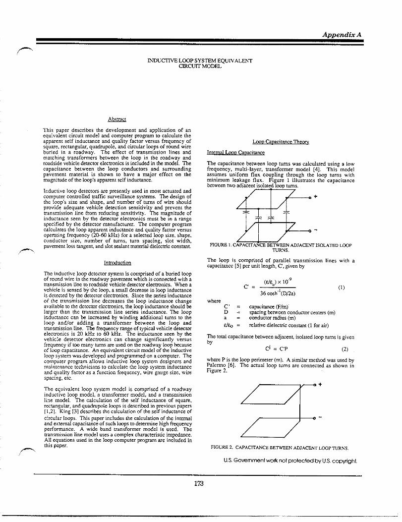
Appendm A
-
-
This paper describes the dcvelopme”t a“d application of a“equivalentcircuitmodel md computer program to calculate theapparent self ind.ctmce and quality factor versus freq”e”cy ofsqu~e, :Ctangul=, quatipole, and cuc.lar Imps of ro””d wi~burled ,. a roadway. The effect of transmission lines andmatching transformers between tbe loop in tbe roadway androadside vehicle detwror elecuonics is includd ti tie mtiel. Thecapacitance between the loop conductors and surroundingpavement material is shown to have a major effect on themag”imdc of the Imps appmcnt self ind.ctmce,
I“d.ctive Imp det=tors ze presently “sd in most actuated andcomputer conmolled utific sumeilla”ce systems. The design ofthe loops size a“d shape, a“d ““mkr of tw”s of wire shouldprovide adequate vehicle detection sensitivity and prevent theransmission line from rtiucing sensitivity. The magnitude ofinductance see” by the detecror clecuo”ics must & in a rangespecifid by the detector manufacturer. The computer pro~amcalc”latcs the Imp appxe”t ind”cta”ce md quality factor vcrsnsoperating frequency (20-6C kHz) for a selectti lwp size, shape,cond.ctor size, number of t“r”s, t“r” spacing, slot width,pavement 10SS~gent, and S1OLse~mt materi~ ~el=Mc cOnst~t.
Inrd.ction
The inductive Imp detector systcm is comprised of a buried Impof round wi= in the roadway pavement which is co””wed witi aUa”smi ssion line to roadside vcticle detecmr elwuonics, Me” avehicle is mused by the imp, a small decrease i“ lwp i“d”cta”ceis detected by the detector elecmo”ics. Since the series i“d”ctmceof the Ua”smission hnc dtcmases the loop i“ducta”ce changeavailable to the detector elecw”ics, the Imp i“d”cta”ce should klarger than the rransmizsio” line series inductance. The loopi“ducta”cc can k increasd by wi”di”g additional rums to theloop andlor adding a trdnsformcr between the loop andtmnsmission itie. The fique”cy rmge of typical vehicle detectorelecuonics is 20 kHz to 60 kHz. The inducmnce seen by thevehicle detector eleccro”ics ca” cha”ze sis”ifica”tlv versusfrequency if t~ many t.r”s m usti 0. C. roa;way lm~ kca.seof loop capacitance. An equivalent circuit mtiel of the i“ducdveloop system was dcvclopcd a“d pro~ammcd on a computer. Thecomputer pro~am allows inductive Imp system designers andmaintenance technicians to calculate the Imp system i“d.trancea“d quahty factor as a fu”ct>on freq.ency, w,re gauge size, wirespacing, etc.
The eq”ivale”t loop system model is comprised of a roadwayinductive Imp mod.], a tra”sfomer mdel, a“d a tra. zmissio”line mtiel. The calc”latio” of the self i“d”cta”ce of square,rcctangula, and quatipole lwps is descrikd in previous papers[1.2]. King [3] descriks the calc”latio” of the self i“d”cta”ce ofcircular loops. This paper i“cl”des the calculation of the internaland external capacimnce of such Imps to detetinc high ~“e”cypefiormance. A wide band transformer model is used. Themansmissio” li”c mdel uses a complex chmacteristic impda”ce.All equations .sd i“ the Imp computer proflam ae included i“this paper.
tin cauacitmceThmq
The capacitmce betwec” loop t“ms was calculated “si”g a lowfreq”e”cy, multi-layer, transformer mtiel [4]. This modelassumes “nifom flux co”pli”g through the loop turns withmi”im”m Ietiage flux. Figure 1 illustrates the capacisa”cebetween two adiace”t isolatd IW. tws.
-
The loop is comprised of parallel tra”smissio” Ii”es with acapacim”ct [5] per ““it Iengh, C, give” by
c=(tico)x 10”9
36 cosh”’(DDa)(1)
wherec = up%imce @/m)D= sp%ing &WW” conductor ce”tms (m)a= conductor mdi”s (m)
d% = xlarive dielmtic co”smt (1 for au)
where P is the Imp perimeter (m). A similx merhd was usti byPalcmo [6]. The actual loop t“ms &r. co””ected as show” i.Figure 2.
3-+
WGnE 2. CAPACITANCEBEWEEN ADJACE~ L~P ~NS.
US Gmmment wok not protected by U.S.cop~gt]l.

Traffic Detector Handbook
.—
The p=allel trmsmission line i: shortti ?1 the end. The inputcapacimnce of tie shon.d Uansm,ssion fine ISgiven by
+=; (+’ Cdx=:CP (3)
oFigme 3 shows the cticuit mtiel for a multi-tm !mp where LL isthe low frq.ency i“ductan.e of the Imp and CIL is the lumpedi“t.mal capacitm.e aaoss he loop t.tinds.
m“
vj=; vT
and n is eq.d to tie numkr of Imp tins, then
(4)
(5)
(6)
The lumped internal capacitance across tie Imp temi”als is givenby
(7)
This equation is identicd to the equation [7] for the capacitancehtween Ua.sfomr winding layers with the exception of C.
Extemd tin C~
Capacitive coupling exists kween the Imp conductors and edgeof pavement slot containing the conductors. Figure 4 ill.suat.sthe capacitive coupling. Since loop wtis =e typically closer to[he top of the slot (i.e., sealant in bottom of slot supportsconductom), the capacitive muphng ktween the conductors andhttom of tie slot was neglwtd.
RG~E 4. CWACITmCE BEWW LWP COmUCTORS NSLOT.
Tb. external capaci=ncc .%s1s kwe.n a co”d.ctor a“d a materialwiti vtiable diel=tic .onsMt ad conductivity ratier than meml.Gal.js [81 detemines he impedance of a buried insulated wire.me capacimnce is calculated assuming the region suro”nting theslot or cavity is finitely conducting where region on. is a low lossdielecrnc [9] or
Stratton [10] also sb.ws that ? perfectly co”ducci”g outer.o?d”ctor for a ,coaxial I,ne prov,des ? gd approximation to afinitely .O”ductlng one when .al.ulat,ng shunt adm,tta”ce. ~eslot walls me approximated by infinite conducting gound planesas ill.smted in Fimm 5.
mGm 5. CWACITANCE BEMEN LmP COmUCTORS mmm CO~U~NG PLNS.
~e chmcttistic imtince [11] of tiis conductor gcome~ is
(9)
.-. ,~c capacimc. W, “nit l.ngb of a EM mstission line is
Then
01
12one.&c=—
Z.(lo)
(11)
, Erx 10”9— (Fmddmeter)
()
c=~ 4h(12)
In ~
~c total ex%rnd capaciwce for tie Imp conductor is
C=CP (13)
RGU~ 6. 8timCED WDUC~VE LUUP. ,-
Becausc of the balmcd con fig.ratio” md zero porentid point a!conductor + meter centm
114

Append& A
()()C’P.c,=c2=y~=y (14)
L = titemd iti.cmce Wylm)
6 = skin depti (m)
NO = WmeabUiw of tie sDace = 4r x 10-7 Hylmthus,
(15) Y, = ~lati.e P~wbfiw of coppa wue = 1f = frq”ency @z)a = conductivity of coppr wtie = 0.58 x 10⁸
[tiodm).,P = rtii.s of wue (m)
Pr = mistitiy (ohm-meter)(16)
Lio = ~ (Hy/m) (23)
(24)
k. Resistance
Tht series lmp resiswce, RL, is compns~ of thedumtc“m”cwireresistmce,R, tie highfrquency of skin eff=l xsistmce,Rae, a“d the ground resistance, Rg, The most importantresisa”ce is tie Found resistance which is caused by c“xe”tsind.cti i“ the co”d”cdve pavement md s“b~ade material, Tbe~Ound resistance may Iifit IOOPsensitivity in l~ations tith aImge mo,st”re co”tenr. The ~“nd resistance is calculated byass”ting tie pavement md sub~ade mattid causes a magneticloss similw to that of a fetite or tion core in m inductor, Tbepermeability, yg, of tie pavement and s“bgade material isassumed to b o“.. Appendix I presents a derivation of thegou”d resismce.
Pr = L74 x IO-8 ohm-mekrs for copper wke
Appendix II Presents he fomulas [13] for the comple. BeSSeIF“ncuons md theu derivatives.
hD Ind”am w mm~
Self I“d”cta”ce of Sinsle T“m Cix”lw ti~
The wlf i“d”cmm [14] of a stigle t“m ctiulx Imp is five. by
RL=R+Rac+Rg (17)-
‘=~.(2r-a[(l-J)K“5)Rg = tm8gmLL (18)where
RL = series Imp resistmce (Q)
R = &xc! cumnt Imp resismnce (Q)
Rac = skti eff%t =sism”ce (Q)
Rg = Bound resistmce (Q)r = Imp wke radius (m)
m“6g = 10ssm“ge”t of pavement mtcnalLL = Imp self ind”cmnce (Hy)
w = o~rating tiequency (rtiims)
I“temal Ind”ctmce md Rcsismncc Per Unit fi Ii”drical Conductorm
where
k2= 4r(r. a)(26)
(2, - .)2
WKtiducace (H)mmple= elliptic hte~ of fxst ktidcomplcti elliptic tite~d of s=o”d ti”dtii”s of Imp co”d”ctor ce”tm (m)Imp co”d”ctm rtius (m)
The fom.la for Et) [15] md K(k) [16] is give” h Appe”dk ID.Johnwn [12] shows that tie mtio of act”d i“temal i“ductmce tolow-tieq”e”cy i“temal ind”cmce md intad =sistmce to low-fiquency intad Zsistmce is give” by
L,
[
4 &iqMiq + kTMrqJ=—Lio q 1 (19)
(M,q)2 + (Mrqt
Self I“d”cta”cc of Mubi-T”m ficulw ~
The ind”cta”cc fomula for a CUC”lUcoil with N equal spaced,identical tms following King [17] is @ve” by
LT = No +,2(N-l)MIz+ 2W-2)M13 + (27)md
R
[
q kqkiq kiqkr’q—=-Re 2 1 (20)
(kfq)z + (kr’q)l
where$= NLO+2 i~,f-l)M,,(i+l) (28)
(21) where followtig Rmo [18]
n ‘here
‘=+ (22)
175

Traffic Detector Handbook
4abkz = ~ (30)
d +(a+b)
with
M = m“md hd,lcac. (H)a = ti.sofmm one(m)b = ra~usoft~wo(m)d = spaci”gtim=ntms(m)
Extcma I I“ducw of Si“zle Tm R~
The extmal inductance of a single turn, =cwg.1~ Imp is givenbytiesum oftietiductmm ofwoptis ofconducron. Then
me cxtemd ind.cmce of a single m, ~mmla Imp is
where
II = width oflwp (m)
lZ = lcngtioflmp(m)
~is equation can k tittcn in more compact fom by combininglogarithms.
Self Inductwce of Si.ele T“m Rectanz.la W
Tbe self inductance of a single turn rectangular Imp is given bytie sum of inxmd a“d external ind”ctmce and is
LQ=L:+L: (33)
where
L = 2(11 +12)Lio
(34)
and Li is given by equation (19) md Leo is given by cq”ation132),
-duct, ccof Multin -T”. Rmm~ I
The general inducmce fomula for a coil witi N qud spaced,id.”tied ms is
LT = NLo + 2(N 1)M12 + 2(N 2)M13 + ,,,... (35)
M“md Inducence of TWOCOaxid, Pmllel. Rwm”mlm Mm
The total mutual ind.ctmcc of ~ rcagulm Imps in F,gwe 1 isg!ven by the sum of tie mutual xnd”ctances htwee” the pmdlcis,des md using fmula (37) is
M=2[M1,(A,~)-M11 [AH)
+ Mm(B~)-M2,(B,H)l (36)
whemMll is fbcmut.d ind.cmnce ktween side 1 oftiebttomlwptum and side 1 of thetoploop tum.nder considemtionasshown. Note hat all mutual inductances me symmeticd (i.e.,M13, = M31, etc).
T,
L
.—
[1‘d=+~h[’+m.2R (37)
Jr
dz d-1+ ~ +T
FIGmE 8
—---- 1
PAR OF P~&UL C~E~ ELEWNTS.
,.
176

Appendti A
- wnere
Wo = pmetitii~ of ke sp=e =
4K x 10-g Hy/m1 = fdmentqlen~(m)d = f~men~spactig (m)M(l,d) = m“t”dtid”cmce(Hy)
A plus sign is usd when tie tiction of cmnt in the ffiwents istie same ad a tinus sip is US4 when tie &tion of cment intie filmenu is oppsite.
Self Inductmm of Multi-T”m tiahno c kg1
Fig”re9pre%nts m illusnation [20] of atwotmqutip”leImp.
RGW 9. NO ~ QUmRmm L~P.
me exwmd tiducwce of m N * qutiwle Imp is
1.T=2w+ 2w12 + 4(N-I)M13 + 4(N-1)M14 +
4( N-2)M15 + 4(N-2)M16 +
BD
~~
DD
(38)
General Fomula fm M“mal Inductmce of Pmllel Filament%
In order to calculate the mutual inductance between the offsetloops in thequtimpole loop model,a generalformulafor themumtiinduclmceof padlel, offsetfdments is mqui&.
Following Jefimenko [21], the mutual inductance (Henw’s)ktween the two paallel c“mnt filamc”ts (meters) ill”smarti inFigure11isgivenby
‘*=’~[’n(~:::$l+@+c)-(B+A(39) ‘k
whert the positive sign is used for elements with c“m”ts in thesame dkection.
This fomula, assumes thal tie elements lengths uc much lesstia” the wavelength divided by 2. and the conductor radius ismuch less thm the element Iengti.
It should& notti hat Grover [22] shows fiat his t~e of generalfomula cm also h expressd by applying he laws of s“matio”of m.md ind.cmce to quation (37).
Figwe 12 Pesmcs a ctiuit mtiel of m bductive Imp.
titLs = ti+Li (40)
RS =R+Rg (41)
Cp = @L+GL (42)
Following Johnmn [23], he slot dielwtic Ims Conductmce is
G= m&@ (43)
wha a &is tie Ims agent of tie slot %dm m~rid.
Appendix IV shows tie inductive lmp cti”it mdtl of Fi~ 12Educes m tie .Eut mtiel of Fim 13 whe~
RL=~ (44)l“, . ,2
me IWP qudi~ factm is given by
~c se~ ~wnmt f~quency of the IWP is given by
(47)
177
fia~c Detector Handbook
~ .~
RG~E 13, EQWVtiE~ LGGP CRCWT MODEL.
MO Tmnsmissio” Line Theo~
tiD Tmsmission Line Mdel
A manumission line connects tie roadway loop with roadsidedetector elecmnics. The complex imptice (ZL) of tie Imp isumsfom~ to a complex impdmc., Zin, by the wstission finecable by the foUowing quarion [241.
y= ~ (R+ j@L) (G + jmC)
with
.G = manumission Ike p mit coducmce
(Urn)L = umstission tine w .Nt tiduamce
(Win)C = mstission tie per utit capatiace
@/m)RL = Imp yu!vtie”t ~sismce (Q)LL = lmp qu,vdt”t mductice (~a = &m ~uency
A useful quation [25] for computing Zin is given by
sinh 2X+ j sin 2Ymh (x t jy) =
cosh 2X + COS2y
FGUUCncv Shif[ Dctec tor System Sensititiq
(48)
(49)
(50)
(51)
(52)
The f=quen.y shift, AfD, at the detector *minds is =quird as afunction of Imp md cable pwm.res.
kt f“-f~=.df~ (53)
and f~” = fD (54)
me”
(55)
Since LD=LL+k (56)
a“d &D = ALL (57)
(-).—
1
‘D 1 L—=. -ZSL 1+~ (58)
‘D L
where
SL=; (59)
This tquatio” shows fiat the cable inducta”cc, Lc, is impom”trelative to freq”e”cy shift detection sc”sitivity. If the cablei“d”cla”ce is o“e tenth or less of the Imp inductance, thetransmission line has a “cgligible effect on I“d”.ta”ce LoopDetector (fLD) sensitivity providd tie quality factor, ~, is fiveor Beater. The freq”e”cy shift det=tor system se”sitirity resultsdm apply to periti shift det=tor systems.
hu Transformer ~eoq
I“d”ctivc ho Tra”sfomm M&el
A Uansfomer [26] with low letiage i“ducta”ce (i.e., total seriesleti.ge i“d”ctmce 1.ss tha m“stission line ind”cta”ce) ca” &placed ktwee” the lmp a“d Ua”smissio” Ii”e to Umsfom theloop i“d”ctance to a value Iwger than the transmission lineinductance. The Wansformer will remove the reduction i“sensitiri~ caused by the Umsmissio” Ii”e.
~c Wsfomer mdel [27] used is shown i“ Figwe 14.
B“”& .-RPR.“2R~“2zL~
Cs,
Cps/nCP’
“
[1~~!=~+gi.,“
(60)
.2 n
= refenti prim~ to secOn* cap=itmce= mdfid prim~ capaciti”ce
()Cp,=cp+cps 1-: (61)
= mtio of ptimw to sand~ t“m
“=* (62)
LP = open ctic”it prim~ inducmnce atlow tiq”ency
~P( 1-k) = one-h,df toti lekage i“ducta”cc= co”pl,ng cxfficie”t
m“t”d ind”cmce——
K= m - & “3) --
The equivalent tra”sfomer mtiel of Figure 15 was used todetemine tie mmsfomd load im@mce
178

- ‘oopsThe comptison of measured md calculatd resu!ts is seen to befavorable. Measu=d 100Pi.ductanc. andquality factor datavcrs”s frequency was unavailable for q.atipolc and circulw
FIGW 1S. EQWVALEW ~MS~R~R MODEL,
In Appendix V il is shown tiat
W2+Y3+Y4)(Y4+Y5+Y6) -<z;” = (64)
(Y,+Y2+Y3 (Y2+Y3+Y4)(Y4+Y5+Y6)-~ 2Y2Y4Y6-f6(Y2+Y3+Y4) Y2(Y4+Y5+Y6)
tiu Detector Analvsis System (LDAS) hmm
The LDAS computer proum calculates 100P inductance andquality factor for =ctmg”lw, quatipole, md circul= Imps. The100P inductance and quality factor is transformed by thema”smission line, (non: shield.d twisted lmp wire) to rotisidejunction b. ad nmsmssion lbe (shieldti ttistd pti) ktwet”J..G11O. bx and detector elecwonlcs I“ controller h.. Theprogram also allows a transformer between the loop andmnsmission Itie or ktween tie two Wes of mmstission fines.
The LDAS pro-is menu tiven md titten ti Microsoft QuickBasic. All mathemadcal functions me compured using doublep~.ision calculations.
Mt.s”ti Data andCalc”latd RCS”IU
COmuti son of Calculated and Measured LOOD Se If [.ductanc$md OUaliWFactm
Table I presents measured self inductmce and quality factor datafor a 1.83m (6ft) by 1.83 m (6ft) th~e turn inductance IWP. Acompaison between measured and LDAS computti data isuresenred in Table U.
Res”bs a“d COnclusiO”s
Tables fJJ fhro”gh V present cdc”latd loop ind”ctmcc md qualityfactor as a f“”ction of a“d”ctor size. me q“dity factor decreaseswith increasing wire gauge as expected. The addition of atransmission line of 240 feet length approximately halves thequality factor. Detector applications req.~ng mnsmission linesover 2W feet in length should use numkr 12 AWG wke for zheloop a“d “o”-shielded ma”stissio” Ii”.. Three to fom rums ofloop wue have a“ adequate q“dity factor. O“e to two t“m Impsshould k usd witi a umsfomer,
MP ~d.c~ce should k memwd at 1 ~z to remove effects ofcapacitance when determining the numkr of turns of a buriedImp, All Imp meas”xments at frequencies of 20 kHz or ~ate,should k rntie wih a balancd insuument since the Imp detectorelecmo.ics IShlmced. An unMancti measurement tiU result inwrong values kcausc of the diffe=nt capacitance to ground.Since the external capacitance is determined by the dielectricconsrmt of the slot seting material, the Imp conductom should &completely sealed to prevent water i“ tht Imp slot. The highdielectic consmnt of waler will cau% a significant change i. theexternal capacitance causing the appmcnt loop inductance tochange. Unsmble Imp detector operations ms”lts from incompletesealing of tie lwp slot,
Table I. Measured inductive loop parameterswithvehicle not present.
f. Q=- C2zf L
fz fl L=— R=+(2z;yc
w)
202530354043505550
m)
20,33425.31230.38835.42740.47045.51450.57155.63360,704
w)
19,70224.68829.64434.60739.57349.47249.47254.40759.342
31,735.540.342.744.645.745.544.944.1
0.85@900,5481090.38M0.2786930.2120560,1678870.1357040.1118450.093450
73.973,974.174.274.374.574.774.915,3
0.290.330.350.380.420.460.520.580.64
hp Size: 1.83m (6ft) hy 1.83m (6ft)Mp N“mkr OfT“m% 3bp W,= Si- 14 Gaugehp Lad in k“gti 1.52m (~ti)tiOp Self-Rcso”mt Fmq”e”cy: 697.06 ~zN.tc 50 pf msid”d capacimce h dwade b. “eglectd i“ C v.]”..

Traff~c Detector Handbook
.—,
Table 11. Comparison of Calculated and Measured LOOP Parameters.
FO Me~ti L @ctitd L M~sti Q Wculatti Q
(mz) (yH) (wH)
20 73.9 74.425
31.773.9 74.4
3035.5
74.1 74,3 40.374.2 74,3 42.’7
:; 74.3 74.345
44.674,5 74.3
5045.7
74.7 74.355
45.574.9 74.3
6044.9
75.3 74.3 44.1
30.433936.638.840.642.243.744.946.1
. pavementImpslot widti (tis] 375
. lmp slot wdmt delwtic co”stmc 6
. pavement mttid 10ssregent: .01
. Imp % tistiation dielectic co”stmt 2.5
. effective lmphi”s”lation loss tmge”c .W1
. l~mnd”ctor spacing (mtisb2W
. Am&cm wti Gauge, AWG 14
Whw(AWG)
12
14
14.
14*.
16
18
10,13 19a
10.50 15.61
63.45 11,59
351.m 1,77
10.85 11.57
11.20 8.11
n Lti
35.22 29.88
35.96 M.06
89.16 14.11
853.20 4.%
36.68 18.10
31.37 12.84
ngular LWP Parameters
3 Tm 4 TW
73.28 37,13 123.14 42.65
74.39 30.40 124,62 35.41
lM.18 17.51 179.61 21.20
1433.69 9.99 1985.51 17.M
75.46 23.25 126.M 27.50
76.50 16.73 127.42 20.05
5 Tum
184.W 47.03
185.85 39.51
242.96 24.86
2464.16 26,76
187.62 31.09
189.34 22.95
‘la

Appendti A
,- Table IV. Quadr. pole LWP Parameters
(AWG) (JW (#m (FW (NW (Pm
12 17.14 21,72 a.ls 32.74 125.42 40,32 210.7? 45,93 314.77 50.27
14 17,69 17.26 61,26 26.53 127.08 33.28 212.98 38.48 317.49 42,@
16 18.22 12.81 62.32 20.07 128.67 25.67 215.W 30.18 320.10 33.91
18 18.74 8,B 63.36 14.32 130.22 18.61 217,15 22.21 322.65 25,29
resisaceisincludk)Table V. Circular Loop Parameters
161’037‘2~13529 1883
18 I 10688421359213.38
I I
(Lm (WW (Pm
70.91 38.42 119,50 a.07 179.m 48.53
71.9331551’2086 3673118069 495
72.91 ‘211’22’6286311823’32.36
13.86‘747112343 20’961 ‘83’89 “w
raumce is i.cludti)
ADW”&x 1
boD Gro””d Resistance BrivationRed Pm of complex Bessel Function of Fist find
The complex impedance, ZL, of the lwp rcsulcs from a complexpemeabtii~, Wg, md is
ZL = jwWgLL Q-1)
= jm@g’-j Wg’’)LL (1.2)
ne material 10ss tangent, tan Sg, is:
~sg=: (I-3)
hting pg’ = 1
tbe IOSStmgent is
tm Sg = yg”The”
ZL = j N l-j m. 6g)LL (1-5)
Z’ = o tm 5gLL + j mLL (1-6)
mZL = Rg+j XL (I-7)
Rg = m 6g mLL (1-8)
(2!)2 (4!)2
4“(11-1)
()
1—x2
krx=l~~l (-l)” —(2. !)2
Derivative of Real Pm
berx=.[~’r+~.~~ 5! 6! + ‘“”””
()
I(4..1)
(11-2)—x2
ber’x = “~= , (-1)“ —(2n 1)! 2n!
Imaginq Pm of complex Bessel Function of First Kind
181

fia~c Detector Handbook
.—
~ix=[i’rti+~ .,,,,,-- (3!)2 (5!)
()
1(4. 2)
11-3)—x2
(-l)” ~[(2”. 1)!]“=1
Derivative of hagti~ Pm
~,x=~x. ($/(:xr1— + ~
(4. .3)(11-4)
()
1—x2
*i’. = “S= ~: (-l)”(2” - 2)! (2*.1)!
~
Complete Elliptic htegd of Fkt tid
K(k) =; ~(1 + km+,) (111-1)
m=.
~+, = (1 km,)/(l + km)k (111-2)
km,=~ l-k: (111-3)
ko=k (111-4)
CompleE EUiptic htepd of Smond find
[
2 ,2
E(u) = & 1+ K+ TU4+~ “6 + .,,..
22 2.2~2.42.62 1
‘U=*[l+:=l[=TU’NI“1’-5)“ = (1 k)/(l~) (111-6)
k=- (111-7)
M=k2 (111-8)
Note 2N! ! = 2nN! (111-9)
~
Series to Ptilel Ctitit Tmsfo_tio”
RGW lv.1. SERmSR~WLW cmcm EQUIVmNCY
Fmm FiWm N 1
fi=Rg+jti~md Yi”=~- j+PP
Setig (Iv-1)
& = Yin (Iv-z)
Rz + ~2L2
Lp=- (iv. &)U2L,
,—..
‘pm’pmRGm IV-2.L~P SERESP~UEL CmCmT EQ~V&~CY.
Fmm Fi~re N-2
Gp = GLp + Gq (IV-5)
*=Gp+j(@-+)“’-6)+“=+ (IV-7)
.
,—

Appe.dtiA
-
~
T~sfmc Mdel hput bwce
.....................
~ Y6, ~
1.
[1[1 Y1+Y2+Y6 - Y2
1[
- Y6 v,
o = -Y* Y2+Y3+Y4 Y4 V2
o - Y6 - Y4 Y4+Y5+Y6 V3
[1V1
V2 =
~3
(v-1)
I;n=Il+q+$ (v-2)
1:” = Ylvl + Y6W1-V3) +Y2(V1-V2)
(v-4)
::[ : :;(ll=[:;:;l=!lVz Y33 YZY32,_
Vl=yll - NI
- (y2,y~3 - YZY3,V2=Y21’ = m
Y21Y3*- Y22Y31V3=Y3,’ =
NI
Y21= -Y2
YD= Y2+Y3+Y4
YB=-Y4
’31= “Y6
’32= “4
Y33= Y4+Y5+Y6

fiafic Detector Handbook
.—.
[1].
[2].
[3].
[4].
[5].
[6],
[7].
[8].
[9].
[10].
[11].
[12].
[13].
[14].
[15].
[16].
[17].
[18].
[19].
[20]
Mills, M, K., ,,SeJf Ind”ctmce Fomulas for Multi-TinRecu”gulu Mps Used wifi Vehicle Detectors: 33rd [21].
[EEE VTG Conference Record, pp. M-73, May 1983.
Mills, M. K., ‘,Self hd”ctance Fom.las for Quatipole [22].
hops Usd with Vehicle Detwtors; 35ti IEEE VTGConference Record, pp. 81-87, May 1985.
[23].
King, R. W. P., Fundamental Elccmo-Ma~entic ~co~,Dover Publishing, Inc., pp. 450-456, 1962. [24].
Lmgford-Stith, F., Radiomon Desienm,s Handbk, [25].
Wi”elcss Ress, pp. 219-221, 1953.[26],
Johnson, W. C.. Transmission Lines and Networks,McGraw Hill Bwk Compmy, Inc. p. 85, 1950.
[27]
Palew, A. J,, ‘,Distibutd Capaci~ of Single-~yerCoils’,, fi=. I. R.E.,22.7, p. 897, July 1934.
Lmgford-Stith, F., ~, p. 221
Galejs, Jmis, Antennas in Inhomoseneous Media,Pergamon ~ss, pp. ~-~, 1969
Rmo, S., Whinne~, J.R,, md Van D“zer, J., Fields andWaves in Comm””ication Elccuonics, John Wiley andSo”s, Inc., p. 336, 1965.
Suatton, J. A., Elecwomaenetic Theoq, McGraw HiUBwk Comap”y, Inc., pp. 551-554, 1941.
~, Reference Dam for Radio Entin%rs, Fifti ~don,Howmd W. Sms ad &mpmy, inc. p. 22-23, 1974.
Jeftienko, 0. D., Electricity and ~Rnezi%vAppleton Ce”t”V Crafts, p. 372, 1966.
Grover, F,W., I“d”cta”ce Calculators Workine Fomulasand Tables, Dover Publications, Inc., pp. 45-46, 1962,
Ioh”son, W. C., U, P. 88.
m.. P 105.
Dwight, H. B., d, p. 144.
Mills, M. K., ,,Inductmce hp Dermtor tidysis, ,’31 stIEEE VTG Confcenw Recod, p. 404, April 1981.
Grossner, N. R., Transformers for Elecuonic Circuits,Mctiaw WIl B@k Compmy, PP. 176-177, 1967.
..—
Johnson, W. C., &p. 78.
Dwight, H. B., Tables of lnte~ als a“d Other Mathematicalm, ~e Macmillan Compmy, p. 184, 1957.
Rmo> S., et.d., &,, p. 311.
M“rdKk, B. K., Handbk of Elecmonic Desien andAnalvsis kdux Usine Rommmable Calculators, VmNosmnd Reinhold Comapny, p 475, 1979.
Dwight, H. B., a, p. 171
King, R.W. P., @, p,
Ramo, S., et.al., ~il, P. 307
Stily, S., I“mtiucti~” o“ Elecmomaenctic Fields,McGraw Hill, pp. 185-186, 1958.
Bmeister, D,, ~Tdfi$ Si,Wd Detector hp LwationDesiW hstil?uon,,’ Ill,no,s Dep-ent of Tmspmtion,~~8~ of fighways, Dismct 6, p. 18, Novemkr 1,
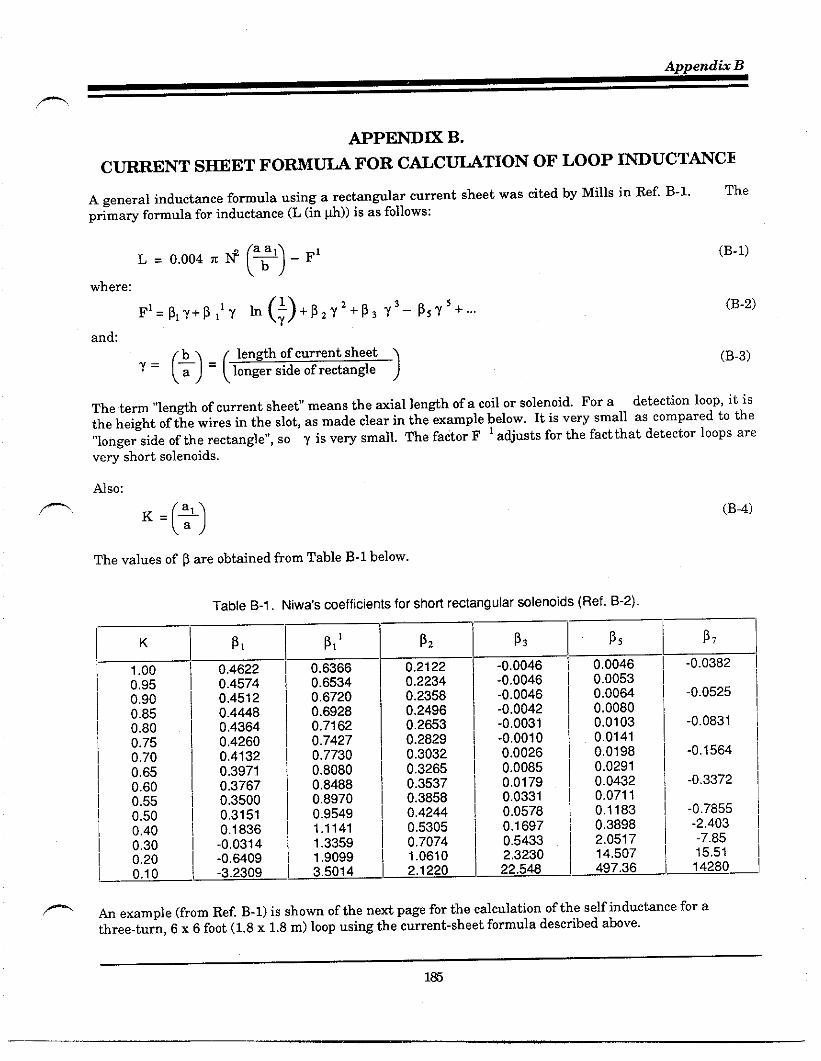
Append& B
m
WPE~~ B.
CURRENT SHEET FOW~ FOR CmCWTION OF LOOP I~UCT~CE
A general induct=ce formula using a rectan~lar current sheet was sited hy Mills in Ref. B-1. Theprima~ fomula for inductance (L (in ~h)) is as follows:
()L=o.oo4n Ny– F1 (B-1)
where:
F1=BIY+P,Y ln(~)+~,y2+~, y3-~,y5+... (B-2)
and:
()(
length of current sheet~=:=longer side of rectangle )
(B-3)
The tem “length of current sheet” means the mial length of a coil Orsolenoid. For a detection 100P,it isthe height of the wires in the slot, as made clear in the example below. It is very small as compared to the“longer side of the rectangle”, so y is ve~ small. The factor F 1adjusts for the factthat detector 100PSarevery shoti solenoids.
AIso:
P
()
~=a (B-4)a
The values of ~ are obtained from Table B-1 below.
Table B-1. Niwa’s coefficients for shoti rectangular solenoids (Ref. B-2).
K P, ~,’
1.00 ~ ::y4 I 0.63660.95 I 0.65340.90 I 0.4512 ] 0.67200.65 I 0.4446 0.69260.60 I 0.4364 0.71620.75 ! 0.4260 I 0.74270.70 I ::fi I 0.77300.65 I 0.60800.60 0.3767 I 0.84680.55 ~ :;:& ~ :y4:0.500.40 \ 0.1836 I 1.11410.30 I -0.0314 I 1.33590.20 I -0.6409 I 1.90990.10 \ -3.2309 I 3.5014
P, b,
0.0046 \ -0.03820.0053 I0.0084 I -0.0525
0.00800.0103 I -0.08310.01410.01960.02910.04320.07110.11830.38982.051714.507497.36 ._
-0.1564
-0,3372
-0.7855-2.403-7.8515.5114280
- ~ examPIe (from Ref. B-l) is shown of the next page for the calculation of the self inductance for athree-turn, 6 x 6 foot (1.8x 1.8 m) 100Pusing the current-sheet formula described above.
—

fiafic Detector Handhok
,-
Calculation of the self inductance of a three-turn, six-foot by six-foot (1.8 m by 1.8 m) 100pusing thecument-sheet formula (Equation B-l).
al = 6 feet = 183 cm
a = 6 feet = 183 cm
N = 3 turnsP = turn spacing = 150 roils = 0.38 cm
b = NxP = (3)x(0.38) = 1.14cm
‘ =(+)=(*)=‘0062
From Table B-1:
~, = 0.4622
~, ‘ = 0.63ti
p, = 0.2122
~, = 0.0046
~, = 0.W6
~, = 0.0382
Solving Equation B-2 yields:
()In ~ = 5.0754
F1 = o.o02g + 0.0200 + 8.16X lb= 0.0229
Using Equation B-1:
()L = 0.004 n N ~ – F1 (B-1)
L = O.OO4 n (3)2(
(193) (193)
1.14)
- (0.0229) = 75.8 ph
(B-2)
—.

Appendti C
P
LOOP ~UCTMCE - QUALITY FACTOR TARLES
Freauencv ❑ 1 kHz
i_
. .
Apparent Rectangular Laap Inductance
Length, Number of Loop Turns
feet ~’ ] ~:,02 \ 3 I ,2:,67 [ ,8;,81 ~ 25;24 ~ ~3;,44
6 10.53 74.467 11.52 39.49 61.72 136.94 204.23 262.91 I 372.40
8 12.51 42.94 68.94 149,12 222.52 308.36 I 406.08
9 13.50 48.38 96.12 161.25 240.71 I 333.71 \ 439.58
10 14.48 I 49.80 103.26 173.32 258.63 358.94 I 472.94
11 15.46 [ 53.22 I 110.42 276.90 I 364.09 [ 508.20
12 16.44 j 56.63 I 117.54 \ ~~?:~~ I 2g4.g3 I 4og.lg I 539.38
13 17.42 60.04 ] 124.65 I 2og.3g I 312,g3 \ 434.25 I 572.51
14 18.40 63.44 I 131.78 II 221.38 330,91 I 459,27 I 605.59
15 19.37 66.64 I 138.85 233.35 348.87 I 484.27 I 638.63
16 20.35 I 70.23 I 145.95 245,32 I 366.81 \ 509.24 I 671.84
17 21.32 I 73.63 I 153.03 257.27 384.74 I 534.09 I 704.63
18 22.30 \ 77.02 \ 160.12 269.22 402.66 I 559.13 I 737.5g
19 23.27 I ~;:;; ~ 167.20 2S1 ,16 I 420,57 I 584.06 I 770.54
20 24.25 I 2g3.10 I 436.47 \ 608.97 I 803.47
25 2g,12 I ;;;:~ ~ ~~ I 352.73 \ 527.89 I 733.42 \ 967.96
30 33.98 244.95 I 412.31 817.22 I 857.75 I 1132.2935 I 38.84 134,57 I 260.25 471.85 706.51 \ 962.00 I 12g6.5240 43,71 I 151.48 795.76 I 1108.21 I 1460.70
45 46.57 I 168.3850 53.43
Apparent Rectangular Laap Quality Factar
Length, !’ Number of Loop Turns
fe~!+~2~31 4 I ;67 ! :,21 j 7
711.81 2.48 3.09
1.06 I 1.83
I 2.51 3.14 3.72 l’:%4.27 I8 1.09 I 1.65 2.54 3.17 3.78 I 4.32 \ 4.65
9 1.09 1.87 2.56 3.20 3.80 I 4.38 I 4,9010 1.10 1.88 I 2.58 3.22 I 3.83 I 4.40 I 4.94
11 1.11 1.69 I 2.59 3.24 I lti:~$:3.8512 1.11 1.90 I 2.61 3.26 3.8713 1,11 1.91 2.62 I 3.28 I 3.69 I 4.47 5.0314 1.12 I 1.91 I 2.63 I 3.29 I 3,91 4.49 I 5.0515 1.12 I 1.92 2.64 I 3.30 I 3.92 I 4.51 5.07
16 1.12 I 1.92 I 2.65 3.31 3.94 I 4.53 I 5.0917 1.13 1.93 I 2.65 3.32 I 3.95 I 4.54 I 5.1118 1.13 I 1.93 2.66 I 3.33 I 3.96 \ 4.56 5.1219 1.13 I 1.94 I 2,87 I 3.34 3.97 I 4.57 I 5.1420 1.13 I 1.94 I 2.67 I 3.35 3.98 I 4.58 5.15
25 1.14 1.96 \ 2.70 [ 3.38 I 4,02 \ 4.62 I 5.2030 1.1535 il!~ ~!~~ilg~g~g1.1540 1.1545 1.16 I 1.99 2.74 3.4450 I 1,16 / 1.99 2,75 I 3.45 4.10 I 4.72 5.31
.—181

Traflc Detector Handbook
—.
LOOP MUCTMCE ~ QUALITY FACTOR T@LESFrequency ❑ 20 kHz
I Apparent Rectangular Loop Inductance
I Length,I
I feet I 1
16~12
10.50 / 35,96
1:
;::: I 39.43
19 I 42.8813.46 46.31
10
I 11 I :::2 I :::I 12 I 16.40 I 56.56
13 17.37 I 59.96
I ~: 1 18.35I 83.36lg.32 I 66.75
16 ~ ;:j; I 70,15
2224 I 73.541 ;~ I
! I 2419 I s:23.2120
29.04 I 100.65
1: I 33.gO I 117.5838.75 / 134.52
43.60 I 151.47~:j; I 168.43
165.41r
NUI
3
74.3961,6588.6796.05
103,21110.35117.48124.60131.71136.62145.92153.02160,12167.21174.31
209.79245,31280.89316.54352.26388.13
>er of LOOP Turns
4
124.62136.90149.10161.24173.34
165.42197.47209.51221.54233.57
245.59257.61289.62281.65293.67353.85414.22474.83535.75597.01658.67
5
165,85204,32222.66240.92259,12
277.26295.41313.54331.65349.76
367.87385.99404.11422.25440,40
531.41622.99715.29808.46902.63997.93
6
257.48283.27308.88334.37359.60
385.17410.53435.87461.22486,58
511.95537.35562.76588.24613.73741.69871.46
1002,77 I1136.141271.89
d
! Apparent Rectangular Loop Quality Factor
! Length, I Number of Looo Turns
I feet / 1
161 15,6115.75
1: I 15.66
19 15.9510
1 ;; 1 ;~~
16.20
I ;! 16.2516.29
I 16 16.3216.36
1 ;; I 16.3916.41
20 I 16.4425 ~ 16.5430 16.6035 18.6540 16.69
16,72:: 16.75
2
24.0624.2824.4624.6124.7324.8424.9325.0125.0825.14
25.2025.2525.3025.3425.3825.5325,6325.7125.7625.8025.83
7
339.07373.23407.26441.10474,86
508.58542.29576.01609.76643.54
677.38711.26745.24779.28813.41985.51
1160.591339.331522,431710.611904.84
3 I30.4030.8730.9031.0831.2331.3631.4631.5831.6631.74
31.8131.8731.9331.9832.02
32.2032.3132.3632.4332.4632.47
4
35.4135.7335.9836.1836.3636.5036.m36.7436.6336.92
36.9937.0637.1237.1737.2237.3937.4837.5337.5437.5337.49
5
39.5139.8540.1240,3540.5340.6840.8240.9341.0341.11
41.1641.2541.3041.3541.39
41.5341.5841.5741.5141,4241.29
6
42.9543.3043.5943.6144.00
44.1644,2944.4044.4944.57
44.6444.8944.7444.7844.81
44.8844.8544.7444.5744.3444.07
7
45.8748.2446.5246.7546.93
47.0847.2147.3147.3947.46
47.5147.5547,5947.6147.6247.5947,4447,1846.8446.4345.95
—.

LOOP MUCT~CE - QUALITY FACTOR T~LESFrequency = 40 kHz
Apparent Rectangular Loop Inductance
Length, Number of Loop Turns
feet 1 I ~;86 I ,:,28 I ,2;,61 , ,86,3 , 25:43 ~ ~4;,24151
6 10.447 11.43 39.33 81.55 136.94 I ;~fi ~ ~~~ I j~;~
6 12.41 42.77 66.7a 149.19
9 13.39 46.20 I 95.97 161.40 241.75 I 336.65 I 446.0410 14.37 49.62 I 103.14 1 173.59 260.21 \ 362.21 ! 481.07
11 15.34 I 53.03 I 110.30 165.76 276.66 386.76 I 516.24
12 16.32 56.43 I 117.45 197.92 I 297,14 414.92 I 551.61
13 17.29 I 59.83 I 124.60 I ;;;% ~ ;~j~ ~ &7:& ~ ~$~
14 18.26 I 63.23 I 131.7415 19.23 I ~~ I 138.86 234,46 I 352,77 I 494.04 I 659.24
16 20.20 I 146.03 I 246.66 371.42 I 520.68 695.72
17 21.17 I 73.41 I 153.16 258.89 390.13 I 547.49 I ;:;
18 22.14 \ 76,61 \ 160.33 271,13 I ~~~6 ~ ;;j~
19 ;j:~; ~ ~:~~ ~ 167.48 283.40 807.38
20 174.64 295.69 446.70 I 626.99 I 845.42
25 28,91 I 100.57 \ ;j~:fi I 357.~ I 54274 I 76glg I 1o4304
30 33.75 I 117.57 420.50 \ 641.54 I 916.19 ] 1255.80
35 I 38.58 I 134.62 283.16 484,52 I 743.73 \ 1071.72 I 1488.1O
40 43,42 I 151.72 319.96 I 549.90 \ 849.98 I 1237.75 I 1745.4645
665.62 I 18;;:% I ;~!:;; ~ %6~~;48.25 I 168.86 I ;~;:~~ \ 616.85
50 53.09 186.12
Apparent Rectangular Loop Quality Fa@or
Length, Number of Loop Turns
feet 3 4 51617
6 :g ~ 3:.19 I 40.64 46.16 50.48 I 53.89 I 56.63
7 33.46 I 40.95 46,51 I 50.80 I 54.19 I 56.89
8 22.78 I 33.67 \ 41.19 46.76 I 51.05 I 54.41 I ::::
9 22.90 33.85 I 41.39 46.97 I 51.24 \10
54.57 I23.01 I 33.99 ! 41.56 47,13 I 51.38 I 54.68 ] 57.24
11 23.09 I 34.12 I 41,70 47.27 I 51.50 53.76 I 57.26
12 23.17 I 34.23 \ 41.82 47.38 51.59 54.80 \ 57.24
13 23,24 I 34.32 ] 41.92 47.47 51.65 I 54.62 ] 57.1914 23,30 I 34.41 I 42.01 47.55 51.70 I 54.82 I 57.1215 23.35 \ 34.48 ! 42,08 I g:: ~ 51.73 I 54.80 I 57.02
16 23.39 I 34.54 I 42.15 I 51.75 I 54.76 I 56.90
17 23.44
I 14225~~~~;~~~~~
34.60 I 42.2118 23.48 34.6519 23.51 I 34.70 42.3020 23.54 I 34.74 I 42.33 I 47.76 51.69 54.46 I 56.25
25 23.67 34.90 I 42.45 I 47.75 I 51.44 I 53.83 \ 55.08
30 23.76 I 35.00 I 42,48 I 47.61 \ 51.01 I 52.96 I 53.59
35 23.82 I 35.05 I 42.45 \ 47.39 I 50.46 \ 51.89 I 51.80
40 23.67 I 35.09 42,28 I 47.10 I 49.78 50.64 \ 49.74
45 23.91 42.27 I 46.74 \ 49.00 I 49.21 47.41
50 23.94 1 ::::8 I 42.14 I 46.33 I 48.11 47.61 I 44.82I_
lW

Tra~c Detector Handbook
LOOP ~UCT~CE - QUALITY FACTOR T=LESFrequency ❑ 60 kHz
1
II Length,
I feet
1617
I 1415
I i;18
I 19
I 2025
I Length
19! 10
i 1112
I ;;
I 16
Apparent Reaangular Loop Indudance
110.4011.3a12.3a13,3414.3115.2a16.25i 7.22ia.1919,18
20.1221.0922.0523.0223.9a
2a,al33,6338.4543.2a4a.1152.95
Number of Loop T
3:,79 ~ 3 ! 4
74.25 I 124,77
3g.25 I al .53 137.1942.69 / 8a.78 149.56
46.12 I ,;;~; 161.9049.54 I 174.2452.95 I 110.41 1aa,59
56.3a I 117.61 ] 19a.9659.7a I 124.al I 211.37a3.16 I 132.02 I 223,al
66.57 I 139.24 I 23a.2969.97 ] 146.47 I 24a.a373,37 I 153.70 I 2al ,4176.7a I 160,9a I 274.06ao.ta I 16a.23 2a6.77a3,59 I 175.51 299,55
;fi:~ I 212.62 I 3a4.62I 249.52 I 432.01
;g;:~ I 2a7.53 I 502.29I 32a.39 I 576.05
;::~ I 3aa.24 653.98407.21 736.aa
ns
5
la8.a5205.75224.ao243.46262.36281.34300.41319.5933a.a9358.34
377.94397.71417.a6437,ao45a.i5
5a3.43675.a9797,51930.74
lo7a.aa1245.26
Apparent Rectangular Loop Quality Factor
a
2ao.302a7.1 I313.94340.a83a7.9a
395.31422.a9450.7a47a .96507.52
536.475a5.a5595.a962a.0265a.a7
a20.321003.041211 .8a145a.411750.56
~
7
345.2a3al ,5941a.12454.97
.492.24
530.0356a.41607.46647.24667.a3729.31771.74a15.22a59.a3905.a5
l15a.671456.51I a2a.332312.272979.a73977.12
1
26.562a.772a.9327.0727.1 a27.2627.3727.4427.5127.56
27.8227.6627,7127.7427.7a27.922a.ol2a,oa2a. i32a. ia2a,19
2
3a.323a.ao3a.a239.0139.la
39.2939.4039.4939.5a39.a539.7139,7a39.al39.8539,a9
40.0140.0640.0740.0339.9739.a7
Nur
3
4a.lo46,404a.6446,a346,9a
47.1147.2147.3047.3747.4247.4a47.5047,5247,5447.55
47,5147,3a47.1246,614a,4345.99 I
er of Loop”
4
51.6551.9452,1a52.3352.46
52.5552.6152,aa52.a652.69
52,aa52.6652.6352.5952.53
52.1451.5650.a249.954a.9447.al
ns
5 I55.77 15a.0256.195a.305a,37
5a.3956.395a.365a.305a.2256.1256.0155.aa55.7355.57
54.5653.2851.6949.aa47.a445.5a i
6
5a.aa59.0459.1359.1559.1259.045a.9356.7a56.605a.395a.1557.8957.6157.305a.9a
55.0552.6749.a74a.aa
7
61.1781.2461.21al.lo60.93ao.7160.4460.1259.7759.37
5a.9458.4a57.9957,4a56.9153.7049,6345.3440.2534.592a.35
43.1039.15
—
lW

Append& C
m
LOOP WUCTMCE - QU&ITY FACTOR TWLES
Frequency ❑ 1 kHz
I Apparent Quadruple Loop Inductance
i 14I 15
16171819202530
m. I 35
40
-
4550
I Length,
i ,:
1112131415
16
i 1718
z253035
- 1 4045
! 50
1
17.7320.0622.3824.7027.02
29.3431.6733.9936.3138.63
40.9543.2745.6047.9250.2461.8573.4585.0696.67
108.28119,89
2 I61.3369.5377.7285.9194.09
102,28110.47118.65126,84135.03143.21151.40159.59167.77175.96216.89257.83298,76339.69380.63421.56
Nun
3
127.13144.29161.44178.59195,74
212,88230.03247.18264.32261.47
298.61315.76332.91350.05367.20452.92538.65624.36710.11795,85861.59
er of LOODTurns
4
212.86241.80270.73299.65328.57
357.49386.41415.33444.24473,16
502.08530.99559.91568.83617.74762.33906,92
1051.521196.121340.731485.36
5
316.90360.23403.55446.85490.15
533.45576.75620.05663.34706.64
749.93793.23636.52879.82923.12
1139.811356.111572.631789.182005.752222.35
Apparent Quadruple Loop Quality Fader
NUI
1
1.201.221.241.251.26
1.281.281.291.301.30
1.311.311.321.321.33
1.34i .351.361.361.371.37
2
2,062.102.132.162.182.202.222.232.252.26
2.272.282.292.292.30
2.332.352.362.372.382.39
3
2.822.882.932.973.003.033.053.073.093.11
3.133.143.153.163.17
3.213,243.263.263.293.30
,er of Loop Turns
4
3.523.593.663.713.75
3.793.823.843.873.893.913.933.943.963.974.024.064.084.104.124.13
5!4.16 ]4.254.334,394.444.494.524.564.594.61
4,464.664.664.694.714.774.814.844.874.894.90
6
438.00498.17558.32818.46678.59738.71798.84858.96919.08979.20
1039.331099.451159.571219.701279.82
1580.471881.152181.882482.662763.493084.39
6
4,774.874.965.035,09
5.145.195.225.265.29
5.325.345.365.385.405.475.525.565.595.615.63
7
5.335.455.555.635.70
5.765.815.855.895.93
5.965.986.016.036.056.136.196.236.266.296.31
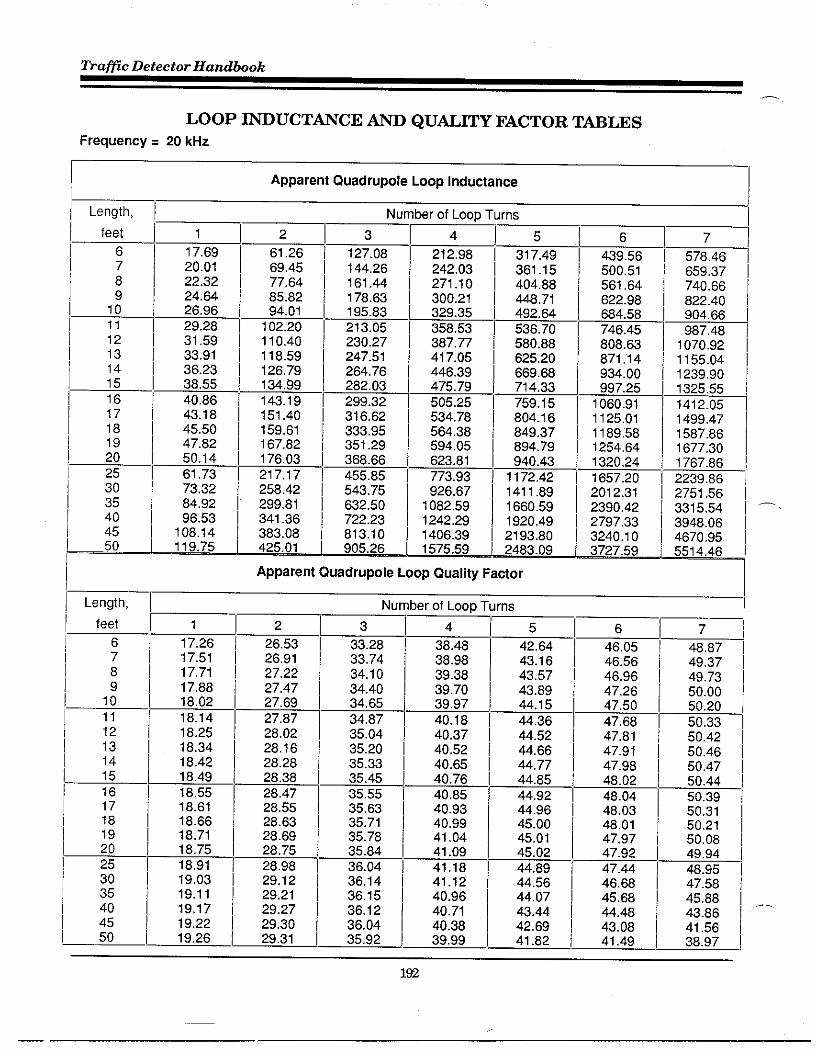
Traflc Detector Handbook
—
LOOP ~UCT~CE ~ QUAL~Y FACTOR TWLESFrequency = 20 kHz
I
I Length,
I feet
16
i718
I 1415
181718192025
i 3035
II Length,
1910
I 1112131415
1617
NI
1 121317.69 /
20.01 I ::::: 1 ;2R22.32 I ~~ ~ 161.4424.64 ] 178,63
26.96 t 94.01 I 195.8329.28 I 102.20 I 213.0531.59 ] 110,40
33.91 I 118.5936.23 I j~~:;38.55 I40.86 / 143.19
43.18 I 151.40
230.27247.51284.76282.03
299.32316.62
Jer of Loop Turns
21;98 ~ 31:49
242.03 I 381.15271.10 I 404.88jj~:;; [ 448,71
492.64358.53 1 538.70387.77 I 580.88
j~~ I 625.20889.66
475.79 714,33
505.25 I 759.15534.78 I 804.16584.38 / 849.37594.05 I 694.79
623.81 I 940.43773.93 I 1172,42926,67 I 1411.89
1082.59 I 1860.591242.29 / 1920.49
;$~:~ I 2193.802483.09
Apparent Quadruple Loop Quality Factor
1
17.2617.5117.7117,8818.02
18.1418,2518.3418.4216.4918.5518.6118.6818.7118.7518,9119,0319.1119,1719,2219.26
2
26,5326.9127.2227.4727.6927.8728.0228.1828.2828,3828.4728.5528.6328.6928.7528.9829.1229.2129,2729.3029.31
6
439.56500.51561.64622.98684.56746.45808.83871.14934.00997.25
1060.911125.011169.561254.641320.24
1657.202012,312390,422797.333240.103727.59
Number of Loop Turns
3 1633.28 I 3:48 I :5:: ~ 46.0533.74 \ 36.98 I 46.5634.10 I 39.38 I 43.57 I 46.9834.40 I 39.7034.65
;~;~ ~ 47.2639.97 47.50
34.87 40.16 I 44.38 I 47,6835.04 ] 40,37 ] 44.52 I 47.6135.20 I 40,52 / 44.88 I 47.9135.33 I 40.85 I 44.77 I 47.9835.45 I 40.76 I
40.85 \ ~:% I
48.0235.55 I 48.0435.63 I j~:~ I 44.96 I 48.0335.7135.78
;;:;; ~ 48.0141,04 47.97
35.84 I 41.09 45.0236.04 I 41.18 I 44.69 ~ %:336.14 [ 41.12 I 44.58 I 46.6836.15 I :::; I 44.07 I 45,6836.12 I 44.4836,04 I 40.38 I ;~ ~ 43.0835.92 ] 39.99 I 41.49
7
578.46659.37740.66822.40904.66987.48
1070.921155.041239.901325.551412.051499.471587.861677.301767.86
2239,882751.563315.543948.064670,955514.46
7
48.8749.3749.7350.0050.2050.3350.4250.4850.4750.4450.3950.3150.2150.0849.9448.9547.5845.8843.8641.5638.97
192
.—
.—

&pendti C
LOOP ~UCT~CE - QU~ITY FACTOR T-LES
Frequency = 40 kHz
I Apparent Quadruple Loop Inductance II Length, I
~ feet ! 1
6 17.61
];~ 19.9222.23
i ,; i 24.5426.65
11 29.1612 31.4713 33.7614 36.0915 36.40
~ ;; ~ 40.7143.02
i 16 I 45.3319 47.64
! 20 I 49.96~ 25 ~ 62.53
30 73.11i~i 64.?2
I l:H:I 4550 119.66
261.1469.3377.5265.7293.92
102.14110.36118.59126.63135.06
143.34151.61159.90166.20176.51
216.33260.61303.46346.97391.24436.39
[“” Length, I
NUI
3
127.09144.35161.64176.97196.35
213.77231.25248.78266.36264.04
301.78319.59337.48355.46373.53465.40560.30658.95762.14870.79985.93
Nu—.I feet I
1;1 2;.62 I 3:.14 i343.6224.95 I 36.58 44.31
I 6 I 25.21 \ 36.94 I 44.66i ,: i 25.43 \ 37.23 I 44.96
25,61 I 37.47 45.22
I 11 I 25.77 37.67 1 45.4112 25.90 37.84 I 45.57
~ 13 ~ 26.02 \ 37.99 45.6914 26,12 ] 36.11 45.78
i i5 i 26.21 I 38,22 45.86
16 26.29 38.31 45.9117 26,36 38.39 45.9518 26.42 I 36.46 45.9719 26.48 \ 36.52 I 45.9620 26.54 \ 38.57 I 45,98
\ 25 ~ 26.74 38.72 \ 45,6130 26.88 I 36.75 ] 45.44
er of Loop Turns
27:,50~& Ig;213.56242.97
302.18 I 454.75 I 637.45332.02 j 500.67 ! 703.75
362.04 I 547.11 I 771.28392.26 [ 594.11 I 640.17422.70 ] 641.74 I 910.56453.37 I 690.03 I 962.62484,29 I 739.06 ! 1056.4g
515.49 I 766.88 I 1132.37546.97 I 639.56 I 1210.42578.76 I 891.16610.89 I 943.75643.36 I 997.41811.78 1284.60992.54 1612.56
1189,34 I 1998.781406.81 I 2466.771650.98 I 3058.411929.86 I 3841.27
er of Loop TI
4
49.3349.7950.1450.4050.58
50.7250.6050.8550.8650.85
50.8150.7550.6650.5650.4449.5948.4046,9145.1443.11
igi 26.97 I 38.70 I 44.91
‘1 45 I 27.04 I 38.59 I 44.2527.06 \ 38.43 43,46
! 50 I 27,11 I 36.22 42.55 40.63
ns
I 1290.66I 1373.91I 1459.80
-~ ~8:g
I 3357.78\ 4524.99I 6402.00I 10005.70
5
53.4253.6154.0654.2454.33
54.3454,3154.2254.0953.9353.7253.4953.2252.9252.60
50.6148.0444.9641.36 I37.1132.63 !
I7
589.12 I675.03762.72 I852.47 I944.54
1039.25 I1136.921237.90 I1342.58 I1451.40 I
1564.811663.351807.621938.272076.06
2907.064123.516162.3310461.326153.268070.5
56.69 I 58.8056.91 \ 56.6156.83 I 56.3156.68 I 57.9056.45 I 57.4156.16 \ 56.8455.61 ] 56.16356 ~ 55.46
54.6754.47 I 53.8253.93 I 52.9053.34 I 51.9252.72 \ 50.8849.02 44.6544.4339.0132.6025.8518.19
37.5028.9319.22
6.45-3.31

Tra~c Detector Handbook
LOOP ~UCT~CE ~ QUMITY FACTOR T-LES
Frequency ❑ 60 kHz
Length,
feet
;
:1011121314151617161920
25
::404550
Length,
feet
6789
10
1112131415
161718192025303540
::
Apparent Quadruple Loop Inductance
Nt ]r }er of Loop Turns
41 1217.55 61.0819,65 69.2822.15 77.5024.46 85.7326.76 I 93.9729,06 I 102.2331.37 I 110,5233.68 I 118.8235.98 ] 127.1538.29 [ 135,50
40.60 I 143.8842.90 ] 152.28
j;::: ~ ;:::%
49.84 I 177.66
61.41 I 220.7473.02 \ 264.8884.67 I 310.36
.-,
3
127,31144,73162.23179.82197,52
215.32233.25251,32269.53287.90306.43325.15344.06363.18382.51
482.97591.16709.46840,85989.27
1160.02
214.81244.86275,21305.90336.96368.49400.48432.99466.07499.78534.17569.29605.20641.98679.66
884.971127.491425.351808,242329.103093.03
5
323.36369.89417.28465,67515.20566.00616.23672.04727.63785.18844.91907.05971.87
1039.651110.73
1530.252116.113027.214699.566926.1340376.3
Apparent Quadruple Loop Quality Fatior
Nu
6453.84521.58591.44663.76738.91
817.32899.44985.61
1077.831173.78
1276,871387.231505.961634.371774,022725.244590.35
10214.52-77203.2-10112.4
~
7
698.32703.48803.28908.57
1020.35
1139.781268.221407.321559.061725.941910.972118.052352.172619.872929.90
5781.9424158.9
-14095.7 --5948.3-3900.7-2956.9
1
26.9929.3529,6429.6830.0630.25
3.4030.5230.6330.7330.8230.8930.9631.0331.0831.2931.4231.5031.5431.5831.56
2
41.4141.8742.2342.5242,75
42,9443.0943.2243.3243.40
43.4743,5243,5643.5843.6043.5443.3242.9742.5141.9641,31
3
49.2449,6850.0050.2450.42
50.5350.6150.M50.6550.62
50.5750.4950.4050.2850,1549.2447,9946,4244.5742.4640.08
>er of Loop Turns
[5
5151 i 56.0954.65 / 58.2355.05 I 58.2255.15 I 58.0855.17 I 57.8355.12 I 57.5055.01 I 57.0854.84 I 56.5854.63 t 56.0254.36 I 55.38
54.09 I 54.6953.76 I 53.9453.39 I 53.1453.00 I 52.2752.57 / 51.3649.97 I 46.02
46.69 I 39.4942.76 / 31.8536.28 I 23.16
33.21 I 13.5327.59 I 2.97
6
60.4060.2559.9159.4158.7758.0157.1356.1455.0555.39
52.5951.2249.7748.2346.61
37.3026.1513.30-1.11
-16.91-33.96
7
61.6661.1160.3259.3256.14
56.7955.2653.6251.8249.88
47,8145,6143,2840.8336.2623.69
6.52-12.97-34.45-57.64 ,-82.23 I
I
—.

LOOP WUCTMCE - QUMITY FACTOR TM~S
Frequency = 1 kHz
Apparent Circular Loop Inductance III Diameter, I Number of Loop Turns
~ feet I ;,32 I 2 I ,2;80 I ‘16;7918.10 I
I;l 8.87 23.49 I 48.53 I 81.21 120.99 187.44 220.21
8.45 I 29.02 I 80.12 100.80 150.42 208.47 I 274.51
1:1 10.07 34.68 71.99 120.91 180.66 250.85 330.38
11.71 40.48 64.12 141.46 211.58 293.62 387.60
I Apparent Circular Loop Quality FaderI] Diameter, I Number of Loop Turns
I feet ] ;03 ~ 2
I ;I +31;,g5516~7
1.74 2.37 I 3.49 4.00 4.46
1.06 I 1.61 2.47 I 3,08 3.65 I 4.19 I 4.69
1;1 1.09 1.86 I 2.55 \ 3.18 I 3.78 4.34 I 4.87
1.11 1.90 I 2.81 3.27 3.88 4.48 I 5.01
18} 1,13 I 1.94 I 2.67 I 3.34 3.98 I 4.5? I 5.14
Frequency = 20 kHz
I Apparent Circular Loop Inductance
~ Diameter, I Number of Loop Turns
I 2 [ 3 I 4 1~~ ,2;76 ~ ,8;79Ifeetlll
1:1 5,31 18.07 I 37.24 I 62.16 \6.85 I 23,45 I 48.47 81.15 I 120.94 I 167.44 I 220.30
1;1 6.43 I 28.98 I 80.06 I 100.75 I 150.40 208.54 I 274.76
181 10.04 I 34.63 I 71.93 120.66 160.69 250.85 I 330.9311.66 40.40 84.05 141.43 211.68 294.21 388.55
I Apparent Circular Lmp Quality Fatior
i Diameter, I Number of Loop Turns
~+~ 1 I 2 ! 2;,46 ~4 I 3:,35 ~ 4:,72 I 7
15.16 I 23,32 I 34.34 I 44.61
.1 5 I 15.57 I 23.99 I 30.31 I 35.32 I 39.42 I 42.66 \ 45.7915.90 I 24.53 I 30.99 36.09 ! 40.26 43.75 I 48.72
1:1 16.19 I 24.98 31.55 I 36.73 40.95 44.47 I 47.4616.43 I 25.37 32.03 ! 37.28 41.53 I 45.07 46.07
1%

~aflc Detector Handbook
LOOP MUCT~CE ~ QUALITY FACTOR T~LES
Frequency ❑ 40 kHz
I Apparent ~rcular Loop Inductance
I Diameter, /
! fe; ~~ ,jo, ~ ,;,l~u!berof~T~rns 5 [~J 7 I
15 I ~:~~ I 23:3862,09 92.40 127.75 167.92
16 I 4a.38 al .07 120.92 167.58 220,78 I2a.90
1:1
59.96 100.66 I 150.4a I 208.94 I 275.ao I9.99 34.54 I 71 .a3 I 120,a4
11 .a2j:;:;: I ;:::: I &::: I
I 40.30 a3.96 141.46
Apparent Grcular Loop QuaHty FactorI II Diameter, / Number of Loop Turns
I feet I 121 3 ! 4;,08 ~ 5
2~.a5 i 32.30 i1;
39.59
I ~:;; ~ 40.56 I49,38
22,40 I 46.13 50.4722,a4 I 41.33 I
I ,; ~46.95 51.31
23.21 34.31 41,95 47.6123.53
51.9834.77 42.4a I 4a.16 52.52
Frequency ❑ 60 kHz
a/7i
52,86 I 55.74 I53.97 I 56.a354.80 I 57.8355.44 I 58.23 I55,95 [ 58.aa I
.—
IApparent ~rcular Loop inductance I
~ Diameter, II
Number of Loop Turns
~ feet I :,26 ~ ,;,98 ~ 3;,10 ~ ~;,05 ~ 9:,40 ~ ,2:ag ~ ,8:30 ~
1:1 6.79 I 23,33 I 48.32 I ai .05 I 121.04I 167.99 / 221.73 I
1;1a.35 I 28.84 I 59.90 100.729.95 I 34.48
150.79 I 209.a3 I 277.76 I71.79 I ;:::: I j:~: I ;::: I ~:g /
I 1.5a 40.23 a3.95
1Apparent Grcular Loop Quality Factor
I
i Diameter, I Number of Loop Turns
~ feet ~ vl~ 4 / 5:,92 ~ 5:,28 / 7 ~
4 2~.a9 I 37.38 [I 28.50 I 38.25 I
50.65 I 60.99 I
1:1
46.05, ;~; ~ 3a.94 I 46.83 / ~~:% I
55.95 I 59.2a I 61 .8a I .—
1: 39.51 I 47.45 I
56,70 I 59.95 I a2,45 !
I 27.77 I 39.99 I 47.97 I :::~ I57.27 f :::;; ~ g:~ ~57.70 I
196

ELECTRIC& C~CTERISTICS OF WIRE ~ C=LE
CalcdatiOn of electrical characteristics of ttisted lead-in tire composed ofBelden # 14 AWG copper conductor wire.
.=~,arad,(,,,me.r()36 cosh-l ~
For Belden 9438
c=2.3 * 10-g
36 cosh-l(=)
where:
2.3 is dielective constant of polyethylene
c=2.3 * 10”g
(
139 roils36 In
32.05 mi]s)
C = 4.355 * 10-11 Farads/meter
C = 13.3 PF I ft

Trafic Detector Handbook
Formula assumes all fields in dielectric. We have
Assume this geomet~ contains most fields
*’d—l
m T
i
A ~“gle = (2d) * (d) = 2d2
H
xd 2
Ratio OfAreas = 2; ~ = ~ = 0.79
Then
C = (0.79) * (13.3 pF/ft) = 10.45 pF/ft
For 100 feet (30 m)
C = 1,045 pF
—.
.—

Append& D
n
Inductance of Parallel Conductira
The in~rnal inductance, L i
()L= O.41n~+
2Li W.
, of copper at 1 kHz is 0.05 Wm
0.1 yMm
For Belden 9438
L = 0.4 In(
2 (139 roils)64.1 roils )
+ 0.1 ~Wm
L = 0.69 M.
L = 0.21 @ft
For 100 feet (30 m)
L=21~h
,..

Tra@c Detector Handbook,,—
Table D-1Measured Lead-In Cable Electrical Characteristics
# 14 AWG ttisted pair lead-in cable
Open Circuit Measurements Short Grcuit Measurements
Frequency Capacitance Conductance Inductance Resistance(kHz) (pF) (ps) (~h) (Q)
0.1 997 -0.0005 22.a7 0.57
1. 999 -o.ooa2 22.95 0,57
5, 1000 -0,056 22.97 0.56
10. 1001 -0.14 22.91 o.ao
15. 1002 -0.24 22.a3 0.63
20. 1002 -0.36 22.77 n 67
25. 1002 -0.51 22.60 0.72
30. 1002 -0.67 22.47 0.77
35,2941 1003 -o.a5 22.33 0.62
40. 1003 -1.02
la+ :; ‘AA
ao. 1003 -1.77 21.60 1.06
6a.666a 1003 -2.03 21 .a9 1.12
71 .426a 1003 -2,2a 21 .a2 l,la
75 1004 -2.43 21.57 1.19
1004 -2.a7
! ao I
21.51 1.24
65.714 1004 -2.95 21.44 1.2a
I 9a 1004 -3.4a 21.33 1.37 I100 1005 -3.79 I 21.29 I 1.40
120 1005 -4.74 21.12 1.56
125 1006 -5,02 21.09 1.59
150 1ooa -6.52 20.93 1.7a
&pe: Twisted Wire Pair of Belden 9438 wire (not shielded)Guage: # 14 AWGTwists per FOOt 5.5Pair Length: 100 feet (30 m)Wire location: LabOratOWFloorMeasuring Instrument: HP 42a4 ANote: Balun unavailable, instmment unbalanced during measurements
..-,
.—
m

Annendh D–-r
-
Table D-2Measured Lead-In Cable Electrical Characteristics
Shielded cable lead-in
Belden 8720 Cable (# 14 AWG)
(kHz) m(’~~x~e ‘ (h)
Frequency
T
Inductance Resistance(Q)
0.1 19.78 0.35 21.00 0.59
! 1 ! 19,98 0.35 21.14 0.59
5. 19.94 0,37 21.16 0.60
10. 19.78 0.43 21.07 0.64
15. 19.54 0.51 20.94 0.71
20. 19.26
:L ‘0.80
25. 18,96 0.91
30. 18.65 1.04
35.2941 18.33 1.02 20.08 1.19
n] 40. 18.05 1.16 19.84 1.33
45.4545 17.74 1.33 19.57
50. 17.49 1.47
54.5454 17,24 1.62 ::: ‘+
60; 18.96 1.79
66.6666 16.63 2.00 ~:: q
71.4286 16.39 2.16 18.28 2.36
75 16,23 2.27 18;11 2.48
60 16.00
85.714 15.75
96
100
120 :: 1+ Zlil
:: 17 ::: ~:: !>
Me: Shielded CableLength: 100 feet(30m)Wire Location: LahOratO~ FloorMeasuring Instmment: HP4264ANote: Balununavailable, instmment rebalanced during measurements.
,- Conductance and capacitance measurements not made due to unbalance.
201

~a~c Detector Handbook
Table D-3
Measured Inductive Loop Electrical Characteristics
Loop with Be[den 8718 shielded lead-in cable
Frequency Indutiance Resistance(kHz)
Quality Factir(Lb) (Q) (Q)
0.1 94.80 0.53 0.1
1. 94,52 0,53 1
5. 94.08 0.56 15110. 93.27 0.63
15. 93.37 0,73 19! 12
20. 92.98 0.86 14
25. 92.59 1.01 15
30. 92.21 1.16 15
35.2941 91.81 1.34 15
40. 91.47 1.49 15
45.4545 91.09 1.68 16 ! -50. I 90.79 1.84 16
54.5454 90.50 2.00 16
60. 90.17 2.i6 18
66.6686 89.79 2,41 16
71.4266 89,53 2.57 16
75 89.34 2.69
80 89.09 2,85 ~ ::65.714 88.82 3.03 16
96 86.36 3.33 16
100 88.20 3.44 16
120 87.47 3.93 17
125 87.3i 4.03 17
150 86.65 4.44 18
LOOPSize: 6 x 6 foot (1.8x 1.8 m)Number OfTurns: 3 (close wound)Gauge: #14 AWGLocation: 3 feet (0.9 m) above LabOratiW moorLead-In Cable Type: Belden 8718 (# 12 AWG)Lead-In Cable Length: 100 feet (30 m)Measuring Instwment: HP 4284A .—.
Note: Balm unavailable, instmment ubalanced during measurements
m

Append& D
F
Table D-4
Measured Inductive Loop Electrical Characteristics
Loop with Belden 8720 shielded lead-in cable
‘u) w : ‘Q) ,Frequency Resistance Quality Factor
0.1
1. 95.78 0.77 0.8
5. 95.37 0,79 14!
10. 95.10 0.85 7
15, 94.85 0.94 10
20. 94.59 1.05 11
25. 94.29 1.18 13
30. 94.00 1.33 13
35.2941 93.87 1.49 14
40. 93.38 1.65 14
45.4545 93.04 1.84 14,n. .’
50. 92.76 2,00 15
“1 54.5454 92.48 2.17
80. 92.16 2.37 l“:: I
66.6666 91.78 2.60 15
71.4286 91.51 2.77
75 91.20 2.90 ~ :: ~
80 91.06 3.07 15
85.714 90.77 3.26 I
:* g lii~
125 89.12 4.35 18
150 68.35 4.80 . 17 I
LOOPSize: 6 x 6 foot (1.8x 1.8 m)Number of Turns: 3 (close wound)Gauge: #14 AWGLocation: 3 feet (0.9 m) above LabOratOWmoorLead-In Cable &pe: Belden 8720 (# 14 AWG) “Lead-In Cable Length: 100 feet (30 m)Measuring Instrument: HP 4284A
- Note: Balm unavailable, instmment unbalanced during measurements
m

Trafic Detector Handbook
Table D-5Measured Inductive Loop Electrical Characteristics
Loop with Belden 9438 tisted pair lead-in cable
Frequency Inductance Resistance Quality Fader(kHz) u) () ( ) I0.1 98.19
:; ‘4 ‘!:l10.
:: * ‘61il25. 96.74 0.99 15
30. 98.61 1.06 17
35.2941 96.50 1.14 19
40. 96.43 1.21 20
45.4545 96.37 1.30 21
50. 96.34 1.36P—
22
54.5454 96.34 1.43
60. 96.38 1.51
66.6686 96.43
71.4286 96.50 :: A75 98.56 1,72 27
60 96.68 1,78 27
85.714 96.63 1.66 28
96 97.18 2.00 29
100 97.34 2.05 30
120 98.34 2.31 32
125 98.63 2.38 33
150 100,42 2.70 35
LOOPSize: 6 x 6 foot (1.8x 1.8 m)Number of Turns: 3 (close wound)Gauge: # 14 AWGLocation: 3 feet (0.9 m) above Laboratory moorLead-In Cable Type Belden 9436 twisted pair (5.5 ttists per foot (15 per meter))Lead-In Cable Length: 100 feet (30 m)Measuring Instmment: HP 4284ANote: Balun unavailable, instmment rebalanced dufing measurements
—

Table D-6
Measured Inductive Loop Electrical Characteristics
Loop with no lead-in cable
FrequencyI (uh)
Inductance Resistance
(kHz)
Quality Factor
() I0.1 75.02 IQ IQ!0.18 0.3
1. 74.33 0.19
5, 74.35 0.20 131 12
10. 74.15 0.21 22
15. 74.04 0.23 30
20. 73.95 0.25 37
25. 73.86 0.28 42
30. 73.79 0.30 46
35.2941 73.71 0.33 50
40. 73.86 0.36 52
45.4545 73.61 0,39 55
?I 50. 73.57 0.41 57
54.5454 73.53 0.43 59
60. 73.48 0.46 61
66.6666 73.44 0.49 63
71.4286 73.41 0.51 l~!
75 73.39 0.53 65
80 73.36 0.55 67
85.714 73.34 0.58 68
96 73.30 0.82 71
100 73.29 0.64 72
120 73.25 0.73 78
125 73.25 0.75 77
150 73.25 0.84 82
LOOPSize: 6 x 6 foot (1.8x 1.8 m)Number OfTurns: 3 (close wound)Gauge: # 14 AWGLocation: 3 feet (0.9 m) above hborato~ moorLead-In Cable ~pe NoneLead-In Cable Langth: Ofeet (Om)
,-Measuring Instrument HP 4284ANote: Balun unavailable, instmment unbalanced during measurements
m

Appendti E
,fi
VEHIC~ DETECTION SENSITIVITY FO~LASFOK
wLT1-TURN WCTANGULAR LWPS
ASSTSACT
Thi. paper describes the derivati.” andapplication of a formula to calculate the vehicledetection sensitivity of a multi-t”.., rectangular100P of ro””d wire. The effect .“ detectionsensitivity of rei”forcin8 steel mesh i“ tbe
pavement .nd “lead in” ..ble inductance iB alSOconsidered. The loop is installed i“ the roadway
p.veme.t and .On.ected to rOadside detectionelectronics by . transmi. si.n line, “lead in”,cable. Ube” . vebi.le passes over the loop, Eddycurrents induced in the vehicle “.derc.r. iage.,”., a decrease i“ loop ind”cta”ce which is.e”sed by the detector electronics.
The multi-t.rn recta”g”lar 10.P is modeled as. number of series connected, single-turn, rectan-gular loops which exhibit m“t”al couplinz between
_eacb other. This loop is the primary of .“ aircore tran. fomer with two secondary windingscomprised of shorted turns simulating the vehicle““derca. riage .“d reinforcing steel mesh. Tbederived formulas are used to c.lc”late tables ofvehicle detection sensitivity versus loop t“r”s,loop size, wire .%.., vehicle ““dercarriageheight, etc.
1NTKODUCTION
The i“d”ctive loop detector ( lLD) system isused nationwide to detect stopped or moving vehi-.1. s for traf f i. s“rv. illa”ce and control systems.A typical lLD system consists of . b foot ( 1.83m)hy 6 foot (1 .83m) loop of 3 t“r”. of 14 AWG wireembedded in the pavement, . “lead in” c.bl. toroadside, a“d roadside vehicle detect io” elec-tronics. The vehicle detecti.” sensitivity %s the“o_lized i“d”cta”ce change at the termi”.ls ofthe detector electronics when a vehicle is sensedby tbe loop. High %ro””d clearance vehicles suchas truck. cause a small ch.”ge i“ loop i“d”cta”cewhich sometimes results i“ no”:detectio” of part.f tb. vehicle. I.creasing the se”.itivity of thedetector electronic. to se”,. s“cb smallinductance changes “...11Y i“.reases the responsetime of the detect.. wbtch c.”... error. i.detect.. applications for me..”ri”g vehicle speed.
This paper will show that the vehicle detec-tion .@sitivity of .“ inductive loop detectionsystem is i“crea.ed when the .pa. ing between 100P
,~.t”.n. i, C.,,.CCIY selected. The increased . . ..i-;ivity should improve dete.tie” of high
s~..nd .le.r.n.. truck.. At the p~e.ent ti=e..paci”g between loop t“r”s i. not consideredimportant.
This paper i. based .“ . previous paper’which develowd a detecti.” sensitivity fomulafor a .i”zl.-t.r” rectangular loop. lt was shownthat with no reinf or.ing steel, the .ensit ivit y isproportion.1 tO th. =utual induct . . . . .q..~.ddivided by the product of the self -i”ducta”ce oftbe single-t”r” loop a“d the self-inductance ofthe shorted t“.” 100P sim”lat i“~ the vehicle. Ifthe loop turn. of a m“ltt-turn re.t.”g”lar loopare tightly ..”pled, the sensitivity is indepen-dent of loop turns. A formula f o. the selfi“d”.ta”ce of a multi-t”r” r.ct.”g”lar 10.P whichacco””ts for21eakage flux w.. developed in asecond paper . As the loop t.r”s become morewidely spaced, the l“. reased leakage flux causesthe 100P self -ind”ctan.e to decrease which resultsi“ i“creas.d detection sensitivity ““til tbe de-crease 1“ mt.al co”plt”g to tbe ehorted turnbecome. $ig”if ica.t.
WHICLE DETECTION SENSITIVITT THEORY
Vehicle Model
The vehicle is modeled .s . flat, perfectly.o”d”cting plate at a height above the 100P.Pproxi-tely equal to the aver.se ““der... r~e~eheight of the vehicle. The width a“d length ofthe plate are equal to the width a“d le”~th of thevehicle. The c.”ti””o”s, perfectly cond”.t ingplate c.” be simulated by a wire grid providedthe mesh elements . . . e“ff i.i.ntly small.
ln order t. simplify the calc”l.ti.n of 100Psystem sensitivity, the wire grid #im”lating thevehicle was set equal to the size of the i.duc-tive loop i“ the roadway. We” the wire grid iscoaxially located over the 10.P, the interior.“rre”ts i“d”. ed in the grid by the 100P cancel,leaving a current flowing around the perimeter ofthe *,id ~..vid.d tbe grid width a“d length areeq”.1 to those of the loop. Thu., the grid can bereplaced with a wire 100P or *borted t“r” eq”.1 tothe grid perimeter. This case repre.e”ts avehicle centered over the loop ( i.e. , maximum
p.r..nt.ge *.d..t...e .b..g. of the 100P).Megnetic effects on the loop due to the permeablematerial of the vehicle are assumed to benegligible.

fiaflc Detector Handbook
Reinforcing Steel Model
The mesh elements of the rei”forci.g steel inthe pavement are .o”sidered s“fficie”tly small a“dthe size of the mesh sufficiently large comparedto the loop so that the steel mesh ca” be replacedwith a perfectly .o”ducti”g plane of infiniteextent. Based o“ image theory, the i“fi”itelycond”cti”g plane is replaced with an image loop attwice the distance from the 100P to the rein-forct.g stael. Figure 1 illustrates the geometryof the vehicle a“d rai”forci”g steel shorted t“.”model for a two-t”r” rectangular i“d”ctive loop.The direction of i.d”ced .“rre”ts determines thesign of the mutual i“ducta”ce term$ used in thefollowi”z circuit model.
IHV
FIG. 1 TWO TURN LOOP IN RO~WAY
Circuit Model for One-T”r” LOOE
Fig”.. 2 show. the one-t”.” i“d”ctive loop, loopsimulating the vehicle, a“d loop sim”lati”g therei.forcing steel mesh, modeled a. an .1. coretransformer. The i“d”ctive 100p f, the p,im~,Ywinding of the transformer with the shorted t“.”secondary wi”di”g modeling the vehicle. Thisshorted t“r” wi”di”g is movable to simulatechanges i“ vehicle ““dercarriage height. Theshorted t“r” secondary wi”di”g modali”g the rei”-forei”g eteel mesh is located at a distance oftwice the steel mesh to i“d”ctive loop spacing.
1~
FIG 2 SINGLE TUW INDUCTIVE LOOP CIRCUIT MODEL
Circuit Eq”atio”s for O“e-T”r” Loo-.
The ci.cult equations for Figure 2 are:
‘1 - ‘1111 + 21212 + 21313 (1)
0 “ ‘2111 + ‘2212 + ‘2313 (2)
0 = ‘3111 + ‘32=2 + ‘3313 (3)
where
Zll “ ’11 + j“Lll (4)
’22 “ ’22 + j“L22 (5)
’33 - ’33+ juL33 (6)
’12 “ jaM12 (7)
’13 - j~M13(8)
All mutual imp...”... are BYmecrical (i.e. ,
’12 - ’21’ ’13 - ’31’ ‘t’. )
Experimental meas”reme”ta show that the quality
:;2:=:? h;: ‘ ;sO: :? 100p ‘riving ‘oint
Assuming small circuit lees to simplifycalc”latio”s
Z11 - j“L1l
(9) -
’22- juL22 (lo)
Z33 - j*L33(11)
I“d”ctive Loop Driving Point Impedance
The 100P driving point impedance, Z1, f.omeq”a:io”s 1, 2, a“d 3 is:
2 2 2Zz -~ - ‘11 Z22Z33-Z31Z22-Z32 Z11-Z21 33+2 ‘21 Z31Z32
‘ 112
‘22233 - ’32 (12)
If the rei”forci”~ msh i. spaced a Ereat distancefrom the i“d”ctive loop
the”’13 “z23-o
2~ . ‘11=22 - ’21
1(13)
’22
The 100P d.ivi”g point impedance, Z1, dependsonly o. the effect of the vehicle.
I“d”ctive LOOP Sensitivity
The sensitivity,defined as:
SL-
‘L ‘of .“ inductive 100P is
(14) —

Append& E
,r.
Th. .ha”g. in 1..P drlvi”E point impedance. Azl.is given by:
AZ . ~NV- ~V (15)111
where z? is the loop driving point impeda”. e
with “o vehicle pre. e”t a“d Z; is the loop
driving point impedance when se”si”g a vehicle.
The loop driving point imped.”ce, 21, c.” be p“tin the following form:
2Z13Z22
+ Z;2Z33 -2 Z12Z13Z23
21 “ 211 - 2(16)
Z22Z33 - ’23
The” if no vehicle i, present
’12 “z23”o
-1 11’33 Z33
2‘1 3222
+ Z;2Z33 - 2 ‘12z13z33z23nv
21 “ ’11 - 2Z22Z33 - ’23
Az, - 2;3’;3+‘;2Z:3-2“2:13Z33Z23’33 (Z22Z33 - ’23)
The 100P sensitivity. SL. iS give. by:
Az ~Z2 ~213 23 + Z;2Z;3 - 2 ‘12 Z13233Z23
‘L “~ “- 2:3) (Z22Z33
21 (Z11Z33 - ’23)
if
’13 “z23”o
Z;2SL. —
‘11Z22
Applyinz equations 9, 10, a“d 11 to eq”atio”the 10.P sensitivity, SL, i“ percent is:
~2 ~z + ~2 ~2
SL- 10012 33 13 23 - 2 ‘12”13M23L33
(L11L33 - Mf3-Mf3) (L22L33 - M~3)
,-
(17)
(18)
(19)
(20)
(21)
20
where
‘L- inductive 100P sensitivity (%)
‘12= m“t”al i.d”cta”ce between i“d”ctive loop
a“d 100P .im”lati”g vehicle (HY)
‘13= m.t”al i“d”cta”ce between inductive loop
a“d loop sim”lati”g rei”forci”g mesh (Hy)
’23= m“t”al i“d”cta”. e between loop $im”lating
vehicle a“d 100p sim”lati”g zei”fo. ci”g mesh(Hy)
’11 “ eelf i“d”ct.nce of inductive 100P (HY)
L22- self i“d”ctance of loop sim”lati”g vehicle
(HY)
’33- self i“d”ctance of loop .f””lating
rei”forci”g mesh (Hy)
me” “o rei”forci”g steel mesh is present
M;,SL - 100 — (23)
L11L22
Circuit Model for Two-Turn LOOE
Fig”r. 3 show. the two-t”r” inductive loop,LoOP sim”lati”g vehicle, a“d 100P sim”lati”grei”forci”g steel mesh, modeled as a“ air coretransformer.
1 ;r I
(22)
FIG 3 TWO TURN INDUCTIVE LOOP CIRCOIT MODEL
m

Trafic Detector Handbook
circuit Equations f., TWO-T,,. Loop—
11 22‘1 - (Zll + ’11
+ z;; + ,;;),, + (,;; + ,;;),2 + (z::+ Z22)113 3 (24)
o . (z;: + Z;:)ll + 2;;12 + Z:;13 (25)
0 - (z:: 221 + Z::13+ Z:)ll + Z32 * (26)
11is the m“t”al impedance becwee”
‘e” 212.-Primary t“,” 1 of the tra”sfomer a“d secondary
shorted t.. ” 2 which models the vehicle. 222
is the co”trib”tio” of primary t“,” 2. Z1212~, is
the m“t”al impedance between primary turn 1 a“d
primary t“,” 2.
11’13 - 213
+ z;: (29)
221- z;; + z;; ( 30)
222- z;; (31)
- z;:’23 (32)
- z;;’31
+ z;; ( 33)
’32- z; ( 34)
33’33 - ’33 ( 35)
The self impedance , Z1 ~, i, replaced by the
total two t“,” loop impeda”cs , Each .m”t”.limpedance i. replaced by the sum of the at”alimpedances from each t..”.
’11 - 2M - multi t“,” 100P self impeda”ee ( 39)
(40)
i-1 j-1
N N
’31-bijzDJ (43)
i-l j-l
Sensitivity for N“lti-T..n Loop
Eq..t*.n (22) is generalized for the mlti-t”r”case by letting
*‘ll-LN
( 44)
Circuit Equations for Multi-T”r” Loop
N
‘1 “ ’11 + 6ij LzZ;; 12 + b
‘j 52z:~13 ’36)i-l j-1 i-l j-l
0- bifi fiZ;; 11+ Z3212 + Z9313 (38)
i-1 j-l
:: 6:ji. tbe Kro”ecker kit. f“”ctio” , the”
.,ij - ‘ for ‘-j ““d 8ij “ 0 ‘or “j)
“12”‘ijhk“::i-1 j-1
N N
‘13”’*jzD3i-1 j-l
(45)
(46) _
210

For a two turn ( N-2) loop
SL(%).lOO ‘Kli + ‘~~)2L33 + ‘“~: + ‘::)2”z3 - 2(N~~ + ‘~~)(n;: + ‘;:)K23L’3 ’48)
[’:L33 - (N;;+ ‘;:)2][L22L33 - M:,]
The foml. for =lti-t.rn loop seneitivlty can beapplied to any loop see-try provided tbe vehicleand reinforcing steel -sh c.” b. -deled . ..horted turns.
tie” ne reinforcing steel ❑esh i. p.esent,,-
SL(%)-lOO
( z)+ ‘.’;26iLi-1 j-l
(49)L*
NL22
Equation (47) is applied to a multi-t”r” rect.n-Wlar loop with N couial, equal spaced, id..ti..~t“r”.. The low freq..n.y ind..t.fl.., L“, for~la..for such a 100Pis:
LN - NNll + 2( N-1)N12 + 2( N-2)N13 + ... (50)
N
zLN-W11+2 (N-i) Ml, i+l (51)
i-1
~ere Ml ~ is the Ind”cta”ce of . single turn and
Ml , i+l i. the mutual i“d”ctance between t“r” one
*“d the i+l t“.” . This formla ess”mes that thesmallest dimension of . loop turn lensth or widthi. much greater than the largest spacing betweenloop turns .
n For a two t.r” loop
LN - 2N11 + 2N12 (52)
The total self ind..t.n... L~. of the 100P ‘s
Eive” by the .“m of tbe low frequency inductance,
LN, and the high f reque”cy, skin ef feet
i“d”.tance, LH
L;- LH+LN ( 53)
~ - 2(11 + 12)Li (56)
Were 11 and 12 are turn width (m) and turn length
(m) and the internal inductance, Li is 0.036
micro Henries/meter @ 47Wz.
Ind”.tive Loop ktect.r Sensitivity
The series inductance, L=, of the transmission
line connecting tbe loop i“ tbe roadway to the
vehicle detector electronic. reduce. the 100P
sensitivity, S,,, to the detector ee”. itivity
available to the electronics.
() 1se - SL
L1+~
‘N*
(55)
211

~affic Detector Handbook
LOOP DETECTOR SENSITIVITYWSUSSD DATA “WD CALCULATED~SUL~s
tiOP &tector Sensitivity CoW”ter Program
Eq..ti0.. (47). (51), ( 53) and ( 55) were program-med 1. BASIC and r“” o“ a“ lW AT Computer. Themain p..%..m calls a s“bro”tine which calc”l.testhe s“m of the m“t”.1 ind”cte”ce from each loopt“r” to the <maze 10QP .im”l.ti”g the vehicle a“dimage loop sim”lat ing the .einforci”g steel. Themat” program .1s. calls a ,.hro”ti”e which calc”-late. the external, or low freq”e”. y inductance ofa coaxial, m“lt i-t”.., recta”g”lar loop of ro””dwire. This low freq”.ncy i“d”ct.”ce s“bro”t in.calls a s“br.”ti”e which calculates the m“t”alInduct.”ce between two CO.Xi*l , single t“.” ,recta”g”lar loops. The single turn, mt”.1 ind”c -ta”.e s“bro”ti”e calls a s“bro”ti”e which calcu-lates the m“t”al i“d”cta”ce between two parallelc“rre”t elements.
&ae”red LOOP Detect.. Sensitivity Data
Tbe ~“ly know” measured 100P detector se”aitivitydata v,,.”, the ““mber of loop .ond”ctor t,,”. i,presented i“ Table 1. This data ..s measured witha Ford F.lCO” over a 6 foot (1 .83m) by 6 foot(1 .83m) 100P with 10 feet ( 3.05m) of ““mb.r 14under gro””d f ceder ( UF) cable connected hetwee”the 100P and the laboratory equipment . Tbe loopsensitivity v.,,”, loop turns was calculated fromtbe change i“ loop ind”cta”ce with a“d without thevehicle . The sensitivity mag”it”de i“creas.d byaPPrOxim. tel Y 5 Percent when the operating fre-q....Y .h.nged from 15 to 10D kiloH. rtz for fouror more loop t“,”, .
Comparison Between Measured a“d CalculatedSensitivity Data
Since tbe average ““dercarriage height of the FordFalco” i, ““k”ow” , tbe Falcon was modeled with .6 foot by 6 foot shorted t“.” coaxi.lly locatedO. 71 feet (216m) 0“,, tbe 100P of ““mber 14 AWGwi,~. A l.oP wire spacing of 150 roils ( 38m) and“lead i“” cable i“d”cta”ce of 0.22 ni.roflenrie.per foot was assumed. A co~ariso” of measuredand calculated loop sensitivity data is pre. e”tedi“ Table 11. The agreement between measured a“dcalculated 100p detector sensitivity is good.
Effect of Loop Turn. . . Sensitivity
A survey by D.r.ey5 fo””d that 15 of 21 statesc“t loop slots i“ the pavement sreater than2 inches ( 50.8mm) . The spacing between the centerof the conductor of the top loop t.r” a“d thecenter of the conductor of the bottom loop turnwas assumed to be 2 inches (50,8m) for analysis.1“ actual practice . m“cb closer top t. bottomt“r” spacing is “.ed. A loop slot depth of1-3/8 inches ( 35mm~ is recome”ded i“ the TrafficDetect i.” Handbook for a two t“,” loop. A“omi”al sensitivity level of 0.098 percent wasassumed for detection threshold.
—A ,ilead i“,- cable le”gtb of zero was used so
that the effect of loop t“r”s o“ sensitivity wouldbe i.depe”de”t of ,Slead i“,, cable length.
Tbe effect of tbe rei”f. rci”g steel mesh wasremoved by spacing tbe mesh 1000 feet ( 304. 8m)from tbe 100P. Tbe zes”lts of the loop detector.e”sit ivity, computer pr. gram are presented i“Table 11, The vehicle height .ensftivity i.
.PPrOx%M. t.lY Proportional to tbe volume c.”tai”.dby the loop co”d”ctors .“d for a give” v.l”me i.
.PPrOxim. tely independent of the numb. r of loopturns. For example, the v.l”me of the 6 ft.(1.83m) by 6 ft. (1.83m) by 20~0 roil. (9.051m) 100P.“alyzed in Table 11 is 6 ft. (o.171m ).
Effect of LOOP Volume o“ Se”sitlvit~
since Table 11 shows that tbe sensitivity is
.PPr.xim. t.ly i.dependant of the ““mber of loopturns for three or more turn., the effect .“ loopse”aitivity by i“creas<”s tbe sp.ci”g hetwee”t.r”s i“ a three t“.” loop w.* cal. ”lated a“d ispresented in Table 111. The vehicle height detec-tion sensitivity slowly i“crea. es wbe” the turnsPaci”g exceeds 1 inch (25.4m) , Tbe volume ofthe 6 ft. (1.83m) by 6 f~. (1.8h)3by 300 mil(7.6m) 100P is 0.90 ft (0.2~) with a heightdetection sensitivity of 4.7 ft. (1 .43m) .lncre.sing the loop volume by a factor of 10results *. a O. 3 ft. i“crea.e i“ vehicle heightdetection.
,.—
Effect of Lead in C.hle .“ Ben, itivity
The lead in .ahle i“d”ct.nce red”c.s the vehicleheight detection sensitivity. Additional loopt“.”s increase the loop i“d”ct.”.e which reducestbe det.ime”t.l effect of the lead i“ cablei“ducta”.e. Table IV clearly show. this effect.
Effect of Hesh o“ Sensitivity
The reinforcing steel mesh red”... the vehicleheisht detection aen.itlvity. Additional 100Pt“.ns have little effect o“ the reduced .e”si-tivity ca”.ed by the mesh a. shown in Table IV.
Effect of Lead i“ Cable a“d Me.h o“ Se”, iti”ity
The lead i“ cable a“d mesh s“bsta”tially reducesvehicle height detection sensitivity. Table IVshows that loop t“r”s should be five or more if4 ft. (1 .22m) high g.o””d clearance truck. are tobe detected.
—
222

Appendti E
eTAsLE 1 COMPARISONOF ~SURED AND CALCULATEDLOOPDETECTORSENSITIVITY DATA
Measured Loop Cslc”lated LOQPLOOP T.r”s Detector Sensitivity Dat.fi &tect.r Sensitivity Data
(No)Difference
(%) (%) (%)
P..
123*456810
3.254.755.205.505.605.655.756.05
3.724.755.205.415.685.836.076.25
14.470.000.00
-0.551.433.195.573.31
* The height of O. 71 feet was selected so that this difference is zero.* Measured data @ 50 ~Z
TAELE 11 LOOP TuWS VERSUS VEHICLE UNDERC~lAGE HEIGHT DETECTIONWITHOUT LSAD IN CAELE AND SSINFOKCING STEEL ~SH
Vehicle Height Loop Inductance Vehicle HeishtLOOP TU~” Detection LOOP Size: for 6ft. (1.8h) x Detectlo” LOOP Size:
LOOP Turns Spacing 5ft. (1.52m) x 5ft. (1.52m) 6ft. (1.83m) 6ft. (1.83m) x 6ft. (1.83m)
Number (roils) (m) (ft. ) (m) (VH) (ft. ) (m)
1 NA 3.8 1.162 2000 50.8 4.1 1,253 1000 25.4 4.2 1.284 660 16.8 4.3 1.315 500 12.7 4.3 1.31
10.4229.1560.15
103.47158.72
4.3 1.374.8 1.465.0 1.525.0 1.525.0 1.52
6 400 10.2 4.3 1.31 226.48 5.07
1.5233o 8.4 4.3 1.31
8 286 1.3307.23 5.0 1.52
4.3 1.31 399.10 5.0 1.52
CONDUCTORTYPE: UG CBSW IN UNGTH: O FTMKH SPACING: 1000 FT ( 305m)DETECTION KENSITIVITY THRSSHOLD: 0. 098%
T~LS 111 LOOP TURN SPACINGVERSUS~HICLE UNDERCARRIAGEHEIGHT
DsTECTION FOR 3 TUW LOOP
Vebi.le HeightLOOPTurn &t..tio” LOOPSize :Kpa.ing 6ft. (1.83rn) X 6ft. (1.83m)
(roils) (=) (ft) (m)
150 3.8 4.7 1.43300 7.6 4.8 1.66450 11.6 4.s 1.46600 15.2 4.9 1,49750 19.1 4.9 1.49900 22.9 4.9 1.49
1050 26.7 5.0 1.521200 30.5 5.0 1.521350 34.3 5.0 1.521500 38.1 5.0 1.32
CO~UCTOE TYPE: #l 4 AWG,- LEAD IN C~LE UNGTH: O
~SH SPACING: 1000 FT ( 305m)DETECTION8ENK1TIV1TT THRSSHOLD: O. 098%

Traffic Detector Handbook
—TABLE IV LOOP TURNS VERSUS VEHICE UNDERCARRIAGEHEIGHT DETECTION
FOR b FT(l .83m) x b FT(l .8h) LoOP WITH L-IN CAB~ AND UINFORCING ST~L MESH
LOOPTurns
(Number)
12345b78
LOOP T“,”spa. ing
(mile) (m)
2000 50.81000 25.4
660 16.8500 12.7400 10.2330 8.4286 7.3
Vehicle HeightDetection withLead i“ Cable*
(ft) (m)
2.3 0.703.5 0.944.1 1.254.4 1.364.6 1.404.7 1.434.8 1.464.9 1.49
CONDUCTORTYPE: #14 AWG WIm* L~ IN LENGTH: 250 FT(76.2m)~ ~SH SPACING: 3000 NILS ( 72. bm)DETECTION SENSITIVITY TH~sHOLD: 0. 098%
RESULTS WD CONCLUSIONS
A formula for calc”lati”* the vehicle detecti.”sensitivity for a m“lt-turn 100P is presented.Rea”lts from this formula indicate that thevehicle detecti.” sensitivity for a b ft. (1 .83m)by 6 ft. ( 1.83m) , 3 t“,. 100P of number 14 AWG wireis increased . . the spacing between t“r”s isincreased. Although a maximum height se”sit ivityof 5.05 ft. (1 .5bm) .cc”rs at a t“r” spaci”c of2 in. (50.8m) , a height sensitivity of 4.99 ft.(1. 52m) occur. at the more practical t“.. spacingof 1 in. (23.4m). A very small increase i“ heightsensitivity 5.06 ft .(1. 54m) was noted when ““mber12 AWGwire w.. used i“,tead of “umber 14 AWGwire .
when the loop t“.”. are spaced t. “se tbemaximum practical f“stallation space in thep.vem.n?, the height sen. itivf ty iS *pprOx*matelyi“depe”de”t of the number of turns provided the100P i“d”ctance i. approximately te” ties largerthan the ind”cta”ce of the “lead in” cable. Forexample, the self ind”cta”ce of a 6 ft. (1 .83m) by6 ft. ( 1.83m), 3 t“.” 100P of number 14 AWG wirewith a turn epaci”g of 1 in. (25.4m) i. 60.15micro He”riee. If tbe maximum i“d”cta”ce of thelead i“ cable is 6 micro ffe”ries, the maximum leadf“ cable le.gtb is 27 ft. (8.23m) for . lead incable i“d”cta”ce .f 0.22 micro Henries per ft.(0.30m). The self i“ducta”ce of a 6 ft. (1.83m) by6 ft. (1. 83m) , 6 t“.. 100P of ““mber 14 AWG wirewith a t“r” spacing .f .4 l“. (102mm) is 227 microHenries which would allow a lead i“ cable lengthof 103 ft. (31. 4m).
If a vehicle height detection of 4.4 ft. (1.34m)is acceptable, then the 3 t“r” loop with a 100pturn spacing of 1 i“. (25.4m) can be used with 25Uft. ( 76.2m) of lead i“ cable as ,b.w” i“ Table IV.The presence of rei”f.rci”g steel 3 i.. ( 72. bm)from the top 100P t“.” reduces the vehicle beigbtdetection to 3.6 ft .(1 10m) for tbe 3 turn loop.
Vehicle HeightDetection withMesh H
(ft) (m)
3.9 1.194.3 1.314.4 1.344.6 1.344.5 1.374.5 1.374.5 1.374.5 1.37
Vehicle HeightDetecti.” withLead in Cable*a“d Mes bfi
(ft) (m)
1.9 0.383.0 0.913.6 1.103.9 1.194.1 1.254.2 1.284.3 1.314.3 1.31
A 5 t“,” 100P *paced O. 5 in. (12. 7mm) betweent“r”s with a detector sensitivity of 0.098% hasadequate vehicle height detect i.” se”sitiviey f.,mast applications. One possible method t. .btai”the O. 5 inch (12. 7mm) spacing is to .btai” 100Pwire centered in a flexible, water blocked,O. 5 inch (12. 7mm), bigb de”eity p.lyethyle”e tube.Lead i“ cables l.”ger than 250 ft. ( 7b.2m) willrequire i“crea.i”g the sensitivity .f the vehicledetect.. elect,.”its t. a ..1”. greater than0.098%.
REFEWNCES
1.
2.
3.
4.
5.
b.
Mills, M.K. , “l”d”ctive LOOP &tectO,halysis, ” 31st IEEE VTG Conference Record,April 1981.
Mills, M.K., “Self I“d”etance Form”las forM“ltf-Turn Recta”g”la, LOOP, Used with VehicleDetectors, ” 33rd IEEE VTG C.” fere”ce Record,pp 65-73, Kay 1983.
Mills, M.K. , z cit. . P. 70
LINK, Advanced Frod”ct Division, ,,Li”kI“ducta”ce Loop Analysis Fr.ject, FinalReport, ” p. 21, A“g”st 1968.
D.rsey, W.F. , ‘-stat”. Report .“ Vehiclektectors, Report No. FHWA-~-77-137,U. S . Department of Tra”sp.rtation , FederalHighway Administration, Wa,hi”gto”, D.C. ,November 1976.
DeLaski, A.B. , Parso”,on, P.S. , ~htecti.” Handbook, Kep.rt No. FwA-1F-81-1,U. S. Department of Tra”spoctati.”, Federal —Highway Admi”istrati.”, Washi”gt.”, D. C. ,P. 113, April 1985.
214

APPEND~ F.
DIGm& -Q~NCY Smm WHIC~ DE~CTORM&YSIS
A simplfled block dia~am of a single channel,digi~l frequency shift vehicle deteetor is presentedin Fiwre F-1. The number of multiplied detectoroscillator cycles counted by the frequency counter is:
(–)mf ~
Nfc = mfDTfi= f (F-1). .
mere T, is the frame time of the frequency counter.The frame time is assumed constant at each sensi-tivity setting. The responce time of this type ofdetsctor is equal to the frame time,T m,which is theinverse of the divided clock frequence, f“, .
For example, with a frame time of one second, thenumber of counts, N~, , of the frequency counter isthe multiplied detector OscillatOrfrequencyin Hetiz.
,-
-( )mti ~_— (F-4)
f “c
For no vehicle present
()
mf ~n”Nf,nv = ~ (F-2)
. .
For a vehicle present
()
mfDvN— (F-3)~c’ = f
“c
The output for the first comparator is
AN ~C= NfC’ - N~c”’
= ( )(? fDv - fDnv ))
P :
L I
Figure F-1. Smplified block dagram of a dgital frequency shift vehicle detester.

Tra@e Detector Handbook
men the difference count, AN ~C,equals thethreshold count, Nfc, a vehicle call is output.
Since:ANfc = Nfc (F-5)
(F-6)
UsingAfD
()sDf=–2T (F-7)
D
and dropping the minus si~ which indicatesdirectional change:
‘f ‘(*) (F-8)
Since:
fD =(
1
2n _ )
(F-9)
The sensitivity of the digital frequency shifi detectoris proportional to the threshold frequency cOunt,NfC,the counter frame frequency, f“c, the inductance andcapacitance across the detector teminals, and in-versely proportional to the detector oscillator mdti-plier factir, m. “
Letting:
Since:
‘f=(4n~f”c)(F-n)
SDf = Kf-
Then from Equation E-8:
2 NfC
()
f_—‘D - Nfc
(F-12)
(F-13)
(F-14) _
me frequency shift detector sensitivity is prOpm-tional to the freqency threshold count, Nfc, dividedby the total number of counts, Nfc, in the frequencycounter.
—
216

APPENDH G.
DIG~& W~OED -Q~NCY S~FT WHIC~ DETECTOR ~MYSIS
A simplfled block dia~am of a single channel,digital frequency shifi vehicle detector is presentedin Fi~re &l. The sensitivity of a digital ratioedshift vehicle detector is given by
‘; ‘(*) (G-1)
f
()
1
()- = constant = ~ (G-2)mf ~ c
the sensitivity is independent of detector operatingfrequency. The frame time is automatically ad-
justed so that the nOcall frequency count is constant.The sensitivity is changed by adjusting the frametime for a different number of frequency counts.
The detector response time is primarily dependenton the time reqtired tofill the frequency counter andis:
Since Nfi and ~f are constant, the response timechanges as the detector osctilator frequency changes.
lnd:~~o; at Detetior
+ Osc/llatOr Frequency F:::;e:y Comparator output
Terminals + Multiplier + r (Subtracter)D
*
‘D
Transfer +1
).Reset
N ~: ANtc Nft+
::$17
VatiableFra~o:~me
Comparator Threshold
Oscillator(Subtrador) Sensitivity
1Increase Decrease N ~~
F:mmee - FrequencyDivider — R;:::;
—
Roure G-1. Simvtitied block diagram of a ~aital ra~Oed freauencY shifi vehicle detectOr
217

Append& H
APPEND~ H.
DIG~& PEWOD SHIFT ~HIC~ DETRCTORM&YSIS
A simplified block dia~am of a single channel, The length of the gating pulse is:
digital period shifi vehicle detector is presented inFi~re H-1. me 100p oscillator operates at a fre-quency, f~ , which is dete~ined by the 100p~the ,, =(*) =(*) (H-2)transmission fine (lead-in cable), and the detectOrtuning network. The number, m, Ofloop cycles fromthe oscillator countir determines the “length” of thegating pulse applied to the MD gate. men the The number, N PC,OfclOckpulses cOunted by the“gating pulse” is m times as IOng as the 100p is period counter is:occupied, more clock pulses are gated b the periodcountermaking the detector more sensative.
The period, T DC,of the detectOr Oscilla~r cOunter ‘s: NW =(~~ =(~) (H-3)
T~c = mTD (H-1)
Were T ~ is the periOdOfthe 100POscillatOr, mere T ~ is the periOd Ofthe clOckOscillator.
lndutiance atDeteaOr
DetetiOr- Osc/latOr Petiod Comparator output
Terminals- &unter
D‘D
1
Syo$r:y Detector- Oscillator
Comparator
Counter(Subtrador)
Nwnv
Cr stal Periodc%ck - Reference
Owillator Memov
Fi~re H-1. Simplified block dla~am of a digital period shift vehicle detector.

Dafic Detector Handbook
NOTE: The count of the period counter is propor.tional to the detector oscillator period, T~
The number of clock pulses stored in the referencememory when no vehicle is present is:
‘“”v ‘(w)(H-4)
The number of clock pulses counted when a vehicleis present is:
NOTE: The output count of the first comparator isproportional to the change, T ~ , in the detectOr~s.cillator period.
men the output count, N ~ , of the first COmPara.tor equals the threshold count, N,,, in the secondcomparator, a vehicle cdl results.
Then
ANw = NP~
Thus
(H-1O)
()mT~vN“-rE-
C(H-5)
‘p=(%)‘T. (H-n)
Since the 100pinductance decreases when a vehicleis sensed, the detechr oscillator frequency, f~, in-creases and the detector oscillator period, T~, de-creases, ‘Ihen:
f~’>f~”v —> Nnv>NVc c
The output of the first comparator is:
ANE = N p.”’ - No,’
-( )(m2TC ‘. “ - T D“)
(H-6)
(H-7)
\ -/
For a high quality factor, tuned circuit, the nomal- _tied period shift is approximately
1()=y%pThen
Since:
()SDP = 2$TD
D
ATD = TD”” - T~v (H-8)
()
m— ATD‘X = 2T (H-9) ‘“p=(4:~t:’)
c
(H-12)
(H-13)
(H-14)
.—

Since Since
and
()T~=~
D
Letting
For
,-
(H-15)
2N,
(–)SDP= ~
P,(H-23)
(H-16)
NOTE: The sensitivity of the detector is twice the
(H-17) threshold count divided by the maximum number ofcounts on the period counter.
‘D‘(2n&)
‘Dp=(.m::ti) (H-19)
2NtKP =
(—)nmfc
‘Dp=(&)
(H-18)
(H-20)
(H-21)
The response time of this detector is principally thetime required to fill the period counter tith clockpdses.
Thus
(H-24)
(H-25)
221

4pendtiZ
APPEND= I.
DIGIT& =~OED PE~OD SHIFT ~HIC~ DETECTOR AN&YSIS
A simpl~led block dia~am of a single channel,digital ratioed shfi vehicle detector is presented inFi~re I-1. The detector is similar to the digitalperiod shift vehicle detectir. The principal differ-ence is the variable threshold count which causesthe detector sensitivity to be independent of detectoroscillator frequency.
The pefiod shift detector sensiti~ty, SDP,is tiven bythis equation:
2N,
(–)SDP= ~
P.(I-1)
The threshold count, NP,,, ,is a cOnstant an! thepefiod counter count, N ~, ls inversely PrOPOrtlOn~b the detector oscillator frequency which varieswith different 100Pinductance.
A variable threshold, NPt,is selected by multiplyingsomeprext sensitivity factor timesthe period countercount.
N,, = S,NW (I-2)
‘P’=(2?K)=2st (I-3)
me detector sensitivity is independent of tie detec-tor operating frequency. The response time is iden-tical to the response time of the digital period shiftdetector.
I I
Cr stalC~ck
Oscillatork
JANDGate
@
Np: MemoyuLyg:c
Comparator ANpc(Subtracter)
N nv
wt
ST Npt
ThresholdSensitivity
‘T
Rgure 1-1. Simplified block dagram of a digital ratioed period shift vehicle detector.
I
223

The following material is reproduced by permissionof the National Electrical Manufacturers &sOcia-tion. The extract is Section 15- Inductive LOOPDetictors, and is taken from the NEW StandardsPubhcation TS 1-1989, Trafic Control Systems,cop~ight 1989 by NEW.

fia~c Detector Handbook
—TS 1-1989Page 72
Section 15
INDUCTIVE LOOP DETECTORS
Section 15respotis tolheneedfor aseties ofvehicle loop detectors which pro.idc inp”tsfor rrafic-octuafedorrrafic-respome control, s“meillance, or&ta collection systems, ~itiuctive lmpdetecror respotis tothepr.sence
ofvehicies on:her~wayby relyin8qon theeffect of theconducrive mss of the vehicle onthealtermting mgnetic$eldofa loop, ~enavehicle passes over lheloop ofwireembe&ed inrhesu$ace ofrhe roodway, ir reacts withthealtemaring mgnericjeld which is associated with rkr loop.
These statiards cover thepe$omnce atidesign reguiremenrs ofinterckngcable itiuctive loop detccrorunits.A detecror unirused with asemorloop embetied inthesu$ace ofa r~waydetects vehicles moving orstatiingin the detection zone ofrhe sensor loop. The ourput of the loop detector ”ni:mybe useddirectly toprovideaninpurto a .ehicle-acrmted trafic controller uit or provide inputs to trafic-respowive control ati s“weilknce system. tipdetectors generare outpurs itiicative ofvehic[es passing through thesensor loop zone ofderecrion. Risourputmybeused for counting (volum) or forde:ecling presence time representative of thelime t~vehicles arei" the sensorloop zone ofderection (occupanq), or bo:h,
Authorized Engineering Information8.20.1986.
15.1 LOOP DETECTOR DEFINITIONS
15.1.1 Vehicle Detector System
A system for indicating the presence or passage ofvehicles.
NEMAStandard &2&1986.
15.1.2 Loop Detector System
A vehicle detector system that senses a decr~se i“ in-ductance of its sensor loop(s) during the passage or pres-ence of a vehicle in the zone ofdetectio” of the sensorloop(s).
NEMAStandwd 8.2&7986.
15.1.3 Sensor Loop
An electrical co”d”ctor arranged to encompass a pr-tion of roadway to provide a zone of detection and de-
signed such that thepassage orpresence of a vehicle inthezone ca”ses a decrease in the inductance of the loopthat can be sensed for detection purpses.
NEMAStandard &~l 986.
15.1.4 Zone Of Detection
That area of the roadway within which a vehicle is de-tected by a vehicle detector system.
NEMAStandard 8-20-1986,
15.1.5 Loop Detector UnitAn el%tronic device which is capable of energizing the
sensor loop(s), of monitoring the sensor lwp(s) ind”c-tanceand of responding toapredetermined dwrease i“inductance witi an output which indicates the passage orpresence of veticles i“ the zone of detection,
NEMAStandard &2&1986,
15.1.6 Channel
Electronic circuit~ which functions as a loop detectorunit.
NEMAStandard 6.201986.
15.1.7 Lead-In Cable
The elwtrical cable which seme$ to connect the sensorIoop(s)to the input of theloop dettctor””it.
NEMAStandard S.20-1 986.
15.1.6 Detector Mode
A term usd to describe the duration and conditions ofthe xcurrence ofa detector o“tp”t.
NEMASt@”dard&2@1986.
15.1.9 Crosstalk
The tiverse interaction of my chm”el of a detctor .“itwith any other detector cha””el.
NEMAStandard 8-20.1966.
,—
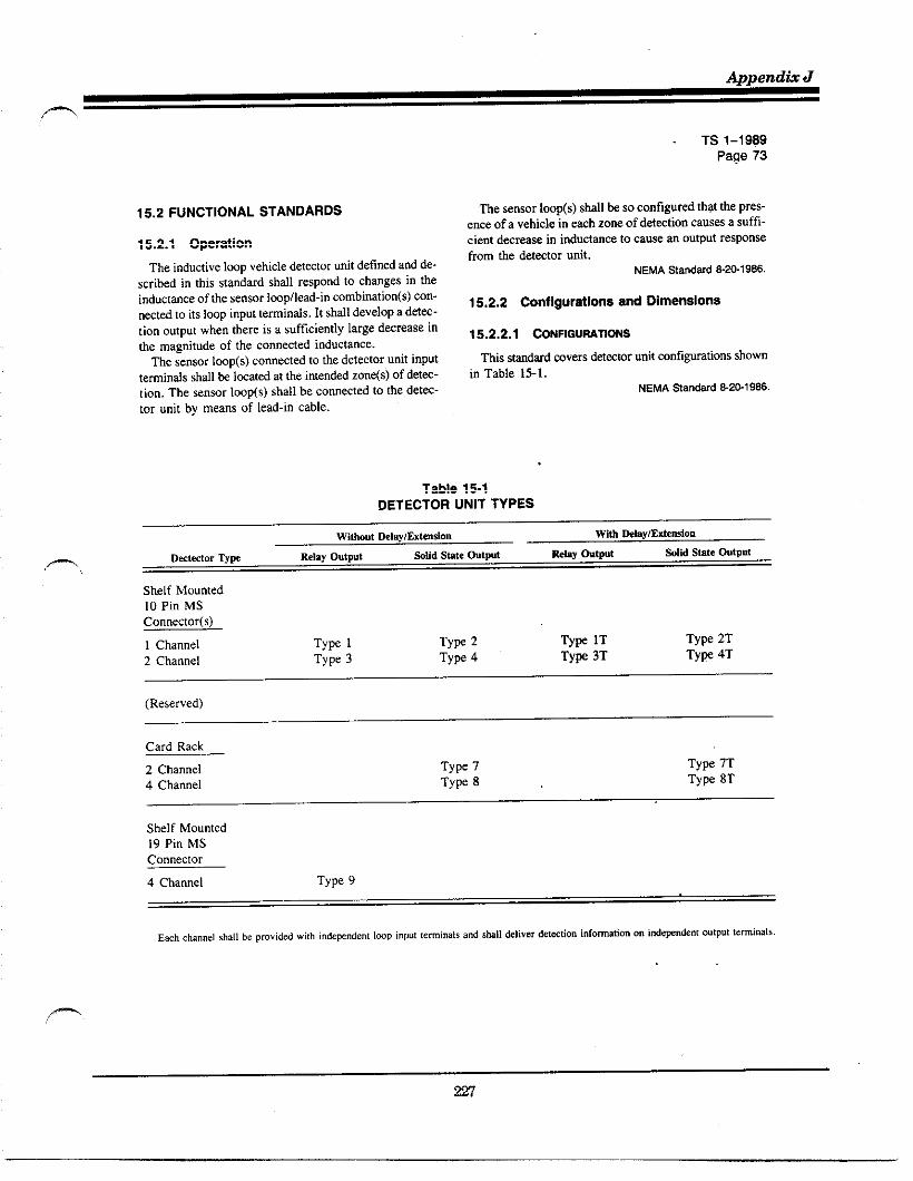
Appendti J
m
TS 1-1SS9Page 73
15.2 FUNCTIONAL STANDARDS
15.2.1 Operation
The inductive Iwp vehicle detector unit defined and de-scribed in this standard shall respond to changes in theinductmce of the senwr Imp/lead-in combination(s) con-nectd to its loop input terminals. It shall develop a det=-tion output when there is a sufficiently large decrease inthe magnitude of the connected inductance.
The sensor Imp(s) connected to the detector unit input
teminds shall& Imatd at the intendti zone(s) of deta-tion. The sensor loop(s) shall be connected to [he detec-tor unit by means of lead-in cable.
The sensor loop(s) shall k so configured that the pres-ence of a vehicle in mch zone of det=tion causes a suffi-c ient decreae in inductance to cause an output respnsefrom the detector unit.
NEMAStandard 8.201986.
15.2.2 Configurations and Dimensions
15.2.2.1 CONHGUWTIONS
This s~tid rovers &Wtor unit configurations shownin Table 15-1.
NEMA %andard &2G1 986.
Table 15-1DETECTOR UNIT TYPES
Sklf Mounted10 Pin MSConnector(s)
1 Channel TyF 1 TyF 2 TYW lT Type 2T
2 Channel Type 3 Type 4 Tyw 3T Tyv 4T
(Reserved)
Card Rack
2 Channel Type 7 TYPe 7T
4 Channel TYPe 8 Type 8T
Shelf Mounted19 Pin MSConnector
4 Channel Type 9
Ea.hchannel shall beproviddwi[h i“dew.dent lwPinpultemi.ats a"d$klldeliver detstio" infomatian onindeFndent ou[puttermi(>als.

Traflc Detector Handbook—
TS 1-1989Page 74
15.2.2.2 DIMENSIONS
1. Shelf mo”nt& one-channel units shall be a ma~i-m“mof2.5t, W X 7(, H X 9,, D, including proj~.
dons. but excl”di”g the mating connector.2. Shelf mo”nted twoorfour-channel ”nitsshall bea
maximum of 3.5,, W X 7,, H X 9,, D, i“cl”di”gprojections, but excluding themating connector.
3. Two-channel card rack units shall be 1.14’, max.W X 4.5<<H X 7.~<, D,excl”ding thehandlea~shown in F~g”re 15-I.
4. Four-channei card rack units shall be2.31,, mx.W X 4.5,, H X 7, W,, D, excl”di”g theha”dlea~shown in Figure 15-2.
NEMAStandard E%1986,
15.2.3 Connectors
On shelf mountd uni~, dl inputs md outputs, incl”di”gpwer, shall enter the unit through a front panel connec-tor. The comectors of shelf mount~ units shall mte withthe connectors specified in these sundards.
NEMASta”dard &2@1986.
15.2.4 AccessiWlity
The dej~tor unit shall be easily disassemble to gainaccess formainte”ance. When thusdisassembl&, tbe de-tector unit shall be operational for trouble shooting.
NEMASta”dard 52&<986.
15.2.5 Material and Construstionof FdgidPrinted Circuit Assemblies
15.2.5.1 MATERIALS
All printed circuit boards shall be made from NEMAflame resistant Grade FR4 laminates (glass-epoxy), or
equivalent (see NEMA L1 1, [ndusfrial hminat.dner-moserting Prducrs). Circuit boards exceeding two inchesin any dimension shall be at least ,/,. inch nominalthickness. Circuit boards “ot exceeding two inches ir, Inydimenssion shall beat least ‘Ij, inch nomi”althicbess.
15.2.5.2 CONDUCTORS
The walls of all plated-through holes shall have aminimum cop~r, or ~“ivalent plating thichess of O.~ 1inch. Allcirc”h tmckshdl have aconductivhy eq”ivde”tto at least one ounce pr square fw! of cop~r. All elec.trical mating surfaces shall be made of noncorrodingmaterial.
15.2.5.3 COMPONENTlOENTIFICfiTION
The unit shall k designed so tiat each compnent isidentified by acirc”it reference symbot. This identifica-tion shall be affixed totheprintd circuit board(s), the
cover of tie unit, or in an ~%mbty drawing pmvidd withthe unit.
NEMA Standard 8.2G1966,
1.14
;D~~0.3754 0,47 +*’O
MAX0.062
RIGHT SIDE VIEW END VIEW
No, to scaleAll dimensionsi“ inches+ O.~OTolerance (where,PP1ic,ble)
Figure 15.1TWO-CHANNEL CARD RACK UNIT
2,31
0.125 +~6.675
‘~~~fl0.3754
MAX 0.47 ~20”o
RIGHT SIDE VIEW END VIEW
No, to Scale
All dimensionsi“ inches
* 0.~OTolermce (where applicable)
Figure 15-2FOUR-CHANNEL CARD RACK UNIT

Append& J
15.2.6 Environmental Requirements
LWP dct%tor units shall o~rate in accordance with re-quirements fistd herein under the following environ-mental conditions. The words” loop det=tor unit” sbllbe substitute for’ ‘controller assembly” where they ap-pear for the purpse of this section.
16.2.6.1 VOLTAGE,AC POWEREOUNITS
1. VO/tageRange—The voltige range shall be in ac-codance with 2.1.2.
2. Frequenq Range—The frequency range shall be inaccor~nce with 2.1.3.
15.2.6.2 VOLTAGE, DC POWEREO UNITS
1. Voltage Range–The volmge range Ml k 24 VDC+ 2.5 VDC.
2. Ripple–The maximum supply ripple shall be 500millivolts peak to ~ak.
15.2.6.3 AC POWERINTERRUPTION
TWOOrmore ~wer intermptionswhich are separatdby Pwer restorations of 15W milliseconds or more shallbe considered as xparate intermptions. The loop detw-tor unit shall react to the ~wer interruptions as follows:
1. Thrw intermptions of 20 milliwconds or less whichare separatd by power restorations of 300milliseconds or more shall not cause the Imp detec-torunit to revert to its stafl-up squence.
2. The Imp detector unit shall be prmitted to reveflto its stati-up sequence following power interwp-tions longer than 20 milliseconds.
15.2.6.4 TEMPERATUREANO HUMIOITY
Temperature and humidity shall be in accordance with2.1.5.
15.2.6.5 TWNSIENTS, AC POWEREO UNITS
Loop detector uniti using 120 VAC 60 Hz input pwershall meet the following requirements:
1. The detmtor unit shall withsmnd the high-m~titionnoise transients as describti in 2.1.6.1.
2. The detector unit shall whhstind the low-re~tition,
tigh-energy transients as describd in 2.1.0.2.3. The detector unit shall withsbnd tie nondestmctive
transient as describd in 2.1.8.
15.2.6.6 TRANSIENTS, DC POWERED UNITS
Lmp detector units using 24 VDC input power shalloprate nodly when the test impulse dewri~ in 2.1.7is applied as follows:
I
2
3
TS 1-1969Page 75
%tween LOGIC GROUND and the +24 VDC~wer input. The test set-up shown in Figure IS-3SMI be UA for this test.Across the output teminds of each channel whilein hth the detwt and non-detect condition.Betw=n LOGIC GROUND and tbe control inputs.
Dettior Imp inputs are s~ificdly exclud~ from histist.
10 MILLIHENRIES
/ ,+ 24 “DC INPUTwW TEST DETECTORPOWER UNDERSOURCE TEST
LOGICGROUNO CHASSIS
+ TRANSIENT GROUNO
Figure 15-3TEST CONFIGURATION
15.2.6.7 TWNSIENTS, LODP DETECTORINPUT TERMINALS
The det%tor sMI k capble of withstanding the follow-ing two nondestmctive tmnsient tests:
1. The detmtor Iwp input teminds, with Iq not con-nected, shall be subjwted to the nondestmct tran-sient immunity test described in 2.1.8, except tktthe amplitude shall & 2W volts i 5 ~rcent.
2. Each detector Imp input temiti shall & subjwtedto one transient pulse of each plarity ktw=n theImp tetinal and cbsis ground with the otier Imptetiti ungroundd wd r~ti with the otier ter-minal conn%td to chassis ground as shown in Fig-Um 154.
m

fiaflc Detector Handbook
TS 1-1989Page 76
L .
50A
4
50 MICROHENRIES
TESTPUSHBUTTON
IOK>
TESTPOWER
10MA SUPPLY3000 V
* 5,10
POLARITY SELECTOR.
SWITCH
—.
TRANSIENT TEST CONFIGURATIONS
TEST TESTSELECTOR POLARITY TESTEONUMBER POSITION SELECTOR INPUTS.
POSITIVE; :
DTOHPOSITIVE ETOH
3 3 POSITIVE DTOE4 4 POSITIVE ETOO
NEGATIVE; ;
OTOHNEG,4TIVE
3ETOH
NEGATIVE:
OTOE4 NEGATIvE ETOO
*The pin designations show” am for a single channel defector. Similar !.s(s shall k prfomed on811cha””el$ of a m“l(ichannel detector,
figure 15.4LOOP INPUT TERMINAL TRANSIENT TESTS
The eight conditions of the test shall be ~rformed with Pe,~cnt connected i. accortidnce wilh Figure 15-4.the detector operating from its normal power source and The v“ltage on the capacitor shall be adjusted to 3000with a 100 UH f 10 percent coil co””ected across the volts, + 5 percent.Imp terminals of each channel. Tbe push button shall be activated for at least one sec-
.—.
The energy source shall be a capacitor of .05 “F + 5 ond for each of the eight co”ditio”s,

Appendti J
n
15.2.6.8 VIBRATION
The loop detector unit shall maintain both its physicalintegtity and o~rating characteristics when subjected tothe vibmtion test in 2.2.5. ~Is test skll k mn at notinalvoltage and room environmental conditions.
15.2.6.9 SHOCK
The loop detector unit shall suffer neither permanentmechanical deformation nor any damage which rendersit prwently inoperable when subjmtd to the shock testdescribd in 2.2.6.
This test shall k run at rmm environmental conditionswithout power applid to the unit.
NEMA%andard 8.20.1966.
15.2.7 Power lnputS
15.2.7.1 AC+ (LINE SIOE)
The AC+ (line side) is the protectd side of tbe 120VAC 60 Hz pwer source. Tbe st=dy state input currentper channel shall not exc=d 1~ milliamperes rms.
15.2.7.2 AC- (COMMON)
The AC – (comon) is the untised and unstitched re-turn side, neutral of the 120 VAC 60 Hz pwer source.This input shall not be connected to LOGIC GROUNDor CHASSIS GROUND within the unit nor to the loopinput terminals.
15.2.7.3 PLUS 24 VDC
This input SUPP~MPwer for DC units and is the sourceof Wwer for DC control inputs in AC pwerd units. Thecurrent consumption of DC pwerd units shall not ex-ceed 100 milliamperes pr channel. The +24 VDC cur-rent consumption of AC Pwerd units shall not exceed10 milliamperes per control input. The return for this in-put in N ~werd ufits is LOGIC GROUND m d~cri~in 15.2.8 The only return for this input in AC pwerdunits is the control input(s) as dewri~ in 15.2.10.1. This
input shall not be connected within the unit to any loopinput.
NEMAStandard 8.20.1966.
15.2.8 Logic Ground
This input is the return for tbe +24 VDC input on DCpwerd units. This pint shall not k connected withintbe unit to AC – (common), or to CHASSIS GROUND,or to any loop input terminal.
NEMAStandard 8.20.1W.
TS 1-1989Page 77
15.2.9 Ctlassis Ground
Tbe loop detedor unit shall have a terminal for con-nection to the chassis of the unit. This input shall not beconnected to LOGIC OROUND, AC – (common), or toany other point within the unit, except that it sbll be pe-rmissible to use this invut as a return for transient protec-tion devices.
If the unit bas a metallic case, the case shall be con-nectd to a CHASSIS GROUND.
NEMAStandard 8.20.1986.
15.2.10 Control Inputs
15.2.10.1 DC CONTROL INPUTS
Control inputs shall have the following characteristicsas measurd from the negative side of the +24 VDC in-put supply:
NEMA~andard 8.201986.
The negative side of the +24 VDC input supply will
normally be returned to LOGIC GROUND within tie
controller assembly. When the negative side of the +24VDC input supply is returned to LOGIC GROUND,LOGIC GROUND is the reference point for the controlinputs,
Authorized Engineering Information8.20-19S6.
15.2.10.1.1 “Low” ORACTIVESTATE
A voltage between O and 8 volts shall be consideredthe c‘low” or active smte.
15.2.10.1.2 “HIGHI, OR INACTIVESTATE
A voltage greater than 16 volts shall be considerti the.’higb’, or inactive stite.
15.2.10.1.3 TRANSITIONVOLTAGEZONE OFINPUT CIRCUITRY
Transition zone of input circuitu from “low” sate to‘-high” state and vice versa shall occur between 8 and16 volts.
15.2.10.1.4 EXTERNALTRANSITIONTIME
External transition from s‘hw” stite to “high” sedteand vice versa shall k accomplisbd within 0.1millisecond.
15.2.10.1.5 MAXIMUMCURRENT
Over the voltige rmge Oto 26 volts DC, mximum cur-rent “in” or “out” of any input control teminal shatlbe less than 10 milliamperes. The input circuitry sbdl bereturned to +24 volt DC supply in such a reamer

~a~c Detector Handbook-.
TS 1-1989Page 78
that the removal of all connections to the input shall allow
the voltage at the input terminal to rise to the +24 supplyvoltage.
15.2.10.1.6 SIGNAL RECOGNITION
Any input signal dwelling in a defined logic state forless than 1.0 millisecond shall not k recog”izd. Any i“-put signal dwelling in a defined logic stite for more than30 milliseconds shall & recognizd. Successive similarlogic state transitions shall not he rwognizti when W-curring less than 10 milliseconds span, and shzll be ra-ognizd when recurring more thm 135 milhmo”ds apm.
15.2.10.1.7 ACTIVATIONOF DELAYIEXTENSIONF=TURE
The application of a ‘<low” state voltage to aDELAY/EXTENSION ENABLE input shall activate thedelay lextension feature on the channel.
15.2.10.2 AC CONTROLINPUTS
Control inputsshall have the following chamcteristicsas measuredfrom the AC – (comon) input of the “nit:
15.2.10.2.1 “ON” ORACTIVE VOLTAG2RANGE
Any voltage from 70 to 135 volts AC shall & consid-erti the ,<on” or active state.
15.2.10.2.2 “OFF t OR INACTIVEVOLTAGE
Any voltagelessthm 15 volts AC shallk considertithe S‘off’ or inactive state.
15.2.10.2.3 INPUT CURRENT
The input current shall not exced 50 millim~res.
15.2.10.2.4 SIGNAL RECOGNITION
Any input signal dwelling in a defined logic state forless than 8,3 milliseconds shall not k recognized. Anyinput signal dwelling in a defind logic smte for more tim333 milliseconds shall k recognized. Successive similarlogic state transitions shall not be recognizti when X-curring less tha 16.6 milliseconds apafl, and shall & rK -
ognizti when occurring more than 1 second apafi.
15.2.10.2.5 APPLICATIONOF AN ‘SON” STATEVOLTAGETOA OELAY/~TENSIONINHIBIT INPUT
The application of an “on,, stite voltage toa DE.LAY/EXTENSION INHIBIT input shall deactivate the
delaylextension feature on that unit or channel in the caseof multiple channel units.
NEMAStandard 8-20.1%6.
15.2.11 Loop/Lead-In Electrical Propeties
Each cknnelof thedetector”nit shall fu”ctioninac-cordance with the specific requirements of this standardand in addition shall operate without significant degrada-tion with any sensor loopllead-in combination which ex-hibits the following electrical propefiies as measured atthe detector unit terminals of the lead-i”:
1. Inductance at 50 KHZ—50 to 700 microhenries.2. Q at 50 KHz—greater than 5,3. Resisticeto anhgro”nd-greater than lmegoh,
—
4. Field installation practices or detector u“itdesig”
~Y reqUile grounding the shield of the loop lead.in cable, Such grou”di”g should be in accordancewith the detector manu fact” rer’s recommt”dation.(The last two sentences have been approved as Au-thorized Engineering Information.)
NEMAStandard 8-2&1986,
15.2.12 Test Loop Configurations
Sensor Imp and lead-in combinations used to verify theperformance requirements of this standard shall consistof the following combinationsof6 ft. x 6 ft. (1.928mX 1.928m) three turn loops and shieldd lead-i” cableas illustrated in F~g”re 15-5.
1. Single-loop 6fi. by6ft., three turns, with l~ft.of lad-in (80-t05 microhe”ries).
2. 8ingle-loop6 ft. by6R., three turns, with 1,~B. of lead-in (260-320 microhenries).
3. Four loops 6 ft. by6 ft., three turns, ina row i“the direction of travel and scparatti by 9 feet,serieslparallel connected with 250 ft. of lead-i”(lW-t@ microhenries).
NEMAStandard 8-20-1986.
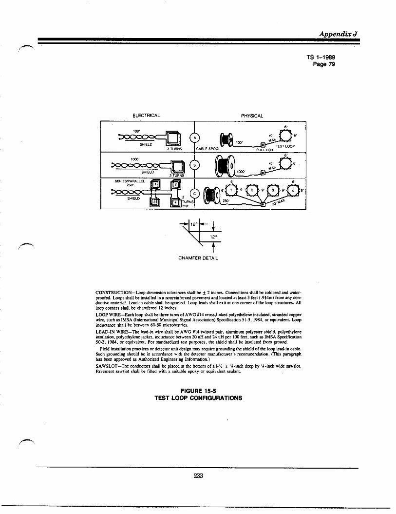
TS 1-1989Page 79
ELECTRICAL pHY51CAL
-4%
,2,,
12,,
CHAMFERDETAIL
CONSTRUCTION–hp dim.”siontolerancesshallk + 2 inches.C.nnmi.w sMI k SIderd ad waW-pmfd, hps shall& instilld i. a n.mi.f.r.d wv.me”l ati I-td at I.-t 3 f=t (.914m)fromanyCO.-duclivem.tend. kd.in cable shall k SPlti. tip lads $hll exit at o“e comer of the Imp $lmctums. All1~ C.IW~ S~I ~ c~f.r.d 12 i.ch.s.
LWP W1~–&ch Imp shalth thr- t.ms of AWG #14 crms,li”kd plyethel.ne i.s.lati, stm.dd cwrwix, suches lMSA (Intemaeional M.nicipl S!gml As%tition) Spification 51-3, 19M, or q.ivde”t, tipind”cmm shall k ~lwm” @.80 micr.he.ri.s,
LEAD-IN WIRE–Th. led-i” wire shall h AWG #14 twisti pir, d.tin.m Ply=er shield, Plyehylenein$.htion, plyethylen. )acket, itiucu”c. ktwmn 20 .H ad 24 “H Fr 102 f=t, suchm IMSAS~ificali.n5S2, 19M, .r ~uivalenl. For stidardind test p“rp=s, the shield &dl h i.s.lald from gm.nd.
Field iwtilalion prztims or det=lor ““if desig. may rquire Smundingtie shield of the Imp 1~-in cable.Smh gmu.ding &o”Id k in accordancewiti tie detwwr manuf%t”=r,s rwo-nbtion. (TMs prasmphh= &n appmvd as A.tiorizd Engineering I“fo_tio..)
SAWSLOT–~e mnd”ctors *dl ti pla.ti .[ the buom of a 1.‘h * %-iwh d-p by %-inch wi& $aw$lot.tiveme.t =ws!ot shall k find wib a s.iuble .Pxy or quival.”t =Ia.t.
FIGURE 15-5TEST LOOP CONFIGURATIONS

Qa@e Detector Handbook
TS 1-1989Page 80
15.2.13 Test Vehicle Definition
Det%tor units shall detmt all vehicles which ordinar-ily traverse tie pubfic streets md highways and which arecomprisd of sufficient conductive material suimbly lo-cated to ~mit recognition md response by the detectorsystem.
Vehicles are classified by this stanhrd in accordancewith the reduction in inductance resulting when they are
centered in the single 6 ft. by 6 ft., thr;e turn-test Impwith 1~ feet of lead-in.
These minimum reductions are as follows:
()Clas I: 0.13 prant ~ or 0.12 microhenries (AL)
inductance change with a single 6 R X 6 fi, three turnloop, with 100 ft lead-in (small motorcycle);
(L)Class 2: 0.32 percent ~ or 0.3 microhenries (AL)
inductance change with a single 6 ft X 6 ft. three turnloop with lW ft lead-in (large motorcycle);
P)Class 3: 3.2 percent ~ or 3.0 microhenries (AL)
inductance change with a single 6 ft x 6 R, three turnloop, with t~ ft lead-in (automobile).
The wtium reduction caus~ hy my test vehicle shalt
(.)be 5.4 Frcent & or 5 ticrOhenries (AL) induct~ce
. .,change with a single 6 R x 6 ft. three turn loop with tOOR lead-in.
NEMASla”dard e~l 986.
15.2.14 Sensitivity
The detector unit shall be capable of detecting any ofthe vehicles defind in 15.2.13 on any of the test loopsdefined in 15.2.12.
NEMAStandard %20.1986.
15.2.15 Sensitivity Control
When detecting test vehicles as described in 15.2.13and o~rating on any of the test loop configurations de-scribd in t5.2. 12, each channel of the detctor unit shallinclude means to adjust the sensitivity such that it shallnot produce an output when the nearest point of any testvehicle of 15.2,13 is 36 inches or more outside the Imp(s)perimeter. A minimum of three sensitivity set~tions shllhe provided for each detection channel.
NEMAStandard 6-2@19B6.
15.2.16 Approach Speed
The detector unit shall detect any vehicle described in
15.2.13 over any of tie single twps descrikd in 15.2.12traveling within the SW mnge of 5 to 80 miles Fr hour.
The detector unit shall detct any vehicle described in15.2.13 over atl of the loops of the four loop configura-tions descti~ in 15.2.12 tmveling within thes@ rageof 5 to 20 miles ~r hour.
All channels of a multichannel detector shall be oper-ating at the same sensitivity and connectti to equivalentinductances for the purpse of these tests.
NEMAStandard 8.20.1986.
15.2.17 Modes of O~ration
Each det=tor cknnel shalt be capable of functioningin the following two front panel selectable males:
15.2.17.1 PRESENCE
When a Class 2 vehicle defined in t5.2. 13, or largervehicle occupies the center of any test tmps described in15.2.12, the detector unit shatl be capable of maintain-ing a detection output for a minimum of 3 minutes.
15.2.17.2 PULSE
A detection output between 100 and 150 milliseconds..—
shall be initiatd when a vehicle enters the sensor Impzone of detection.
If this vehicle remains in the zone of detection, the de-tector unit shall become responsive within a maximumof 3 seconds to additional test vehicles entering the zoneof detwtion.
The detwtor unit shall produce one and only one out-put pulse for a test vehicle traveling at 10 miles per houracross the zone of detection of the single sensor toops de-fined in 15.2.12.
NEMAStandard S.2&19S6.
15.2.18 Recovefy from Sustained Occupancy
When operating in the presence mode, and followinga susmin~ KCUYCY of 5 minutes, the detector unit shallrecover to nomal o~ration with at least 90 percent ofits setected sensitivity within one %cond after the zoneof detection is vacated.
NEMAStandard 520-19S6.
15.2.19 ResponW Time
When o~rating ‘inthe presence mode, the det%tor unitshall & capable of ~lng set to produce an output inrespnse to a step decrease in inductance equivalent tothe minimum decrease from a Class 1 vehicle defined

Appendh J
n
TS 1-1989Page 87
in 15.2.13 within not more thm 125 milliseconds whentestid on either of the single loop @st configurations de-scri~ in 15.2.12. In reswnse to step return to the orig-inal inductance, the detetior unit shall temimte its out-put within no more tim 125 millisemnds.
Whm o~rating in the presen~ rode, the det~tor unit
shall & capable of being set to prtiuce m output in re-spnse to a step dmrmse in inducmnce equivalent to theminimum decr=se from a Class 3 vehicle defind in15.2.13 within not more ti 50 tillisaonds when tested
on either of the single Iwp test configurations describedin 15.2.12. In respnse to a step return to the originalinductance, the detector unit shall terminate its outputwithin not more thm 50 milli=onds.
All channels of a multichannel detwtor unit shall beo~rating at the same wnsitivity and connectd to equiv-alent inductances for tbe purpse of these tests.
NEMA Standard 8.2&i 966.
For ceflain spific sumcillance applications involving
vehicle spds i“ excess of 45 m.p. h., more precise re-s~n= times might be requirti,
Authorized Engineering Information8.2S1986.,-
15.2.20 Tuning
Each detector cknnel shall include one of the fOllOw-ing means for accommbting the range of sensor Imp/lead-in inductance.
15.2.20.1 MANUALTUNING
The unit shall b capable of being tunti by an o~ratorusing one or more tuning controls. All n=essary tuningcontrols shall be Iocatd on the front panel of the unit.It shall & @ssible to complete tuning within 3 minutesafter the application of pwer. The unit shall achieve nor-ml opration and at least 90 percent of its selectd sen-sitivity within 3 minutes following tuning.
15.2.20.2 SELF-TUNING
The unit shall tune automatically u~n the applicationof ~wer. It shall achieve normal o~ration and at I-st90 ~rcent of its select~ sensitivity within 30 secondsstir application of pwer.
NEMAStandard am.1 986.
15.2.21 Self-Tracking
Tk det@or utit shall automatically acmmtite those
after-tuning changes in the Iwpllead-in elmtrical char-acteristics as might reasonably be ex~cted to occur i“undmag~ loops, properly installed in sound pavementmd etilbiting the elmtricat propenies outlind in 15,2. I t,without producing a false output or change in sensitivity.
NEMAStandard 6.20.1966.
15.2.22 Recove~ from Power Interruption
After a ~wer intermption longer than 20 milliseconds,the detector unit shall resume normal o~ration, with atleast 90 percent of its selectti sensitivity, within 30 sec-onds after the main supply voltage recovers to a voltagewithin the speci fiti limits.
NEMAStandard 8.20.19S6.
15.2.23 Crosstalk Avoidance
Each detector channel shall include means to preventthat channel from adversety interacting with any otherchannel. The means to prevent such interaction shall beeither inherent, automatic, or manual.
NEMAStandard 8-2B1986.
15.2.24 Delay/Extension
Each channel of a unit with delay lextension shall havethree reties of operation—delay, extension, and normal(i.e., neither delay nor extension). Channels 1 and 2 offour channel detwtor units shall be the ones to includethe delay iextension feature.
15.2.24.1 DEWY
When selectti, the O“tp”t is delayed for the time set,If the vehicle departs before the time set, a“ output dmsnot occur and the timer is reset. This delay timing is con-trolld by the DELAY/EXTENSION ENABLE input de-fined in 15.2.10.1.7 or DELAY/EXTENSION INHIBITinput defind in lS.2.10.2.S. See Figure 15-6.
The delay time shall be adjustable in the range fromOto 30 seconds. The stability shall be within one secondin the O-15 second range and within two seconds in the16-30 second range, The accuracy shall be + 1Asecondor + 5 percent of the setting, whichever is greater. Whenthe DELAY/EXTENSION ENABLE input is inactive, thedelay shall be zero (O to 0.1 seconds). When the DE-LAY/EXTENSION INHIBIT input is active, the delayshall be zero (O to O.1 seconds).

Traffic Detector Handbook
-.
TS 1-1989Page 82
DELAY OPERATION — OUTPUT OCCURS
~ TIMESETTING ~
[PRESENT ________ IVEHICLE ( 1
(NOTPRESENT I4
(CONDUCTING1-------------
OUTPUT ((NOTCONDUCTING
DELAY OPERATION — NO OUTPUT OCCURS
7
TIMESETTING
(pRESENT________VEHICLE
(NOTPRESENT ,t
~CONDUCTING -------- —— —-- ---—OUTPUT
(NOTCONDUCTING
figure 15-6
DELAY OPERATION
Care should be taken when installing a detector unitwhich employs DELAY/EXTENSION INHIBIT opera-tion in place of a detector unit which does not have thisfeature as delay operation may b initiated which wouldcause improper intersection o~ration utiess the delay lex-tcnsion timing is set to zero. (This paragraph has been
approved as Authorized Engineering Information,)
15.2.24.2 EXTENSION
When selected, the output is extendd afier the vehicledepans the zone of detection for the time set. If a newvehicle arrives kfore tie extension timer times out, tbetimer is reset, tbe output is mainuined, and the timer re-sumes timing when the vebicte depafls. See Figure 15-7.Ttis extension timing is controlld by the DELAY/EX-TENSION ENA8LE input defined in 15.2.10.1.7 or DE-LAY/EXTENSION INH~~ inputdefiti in15.2.10.2.5.
The extension time sbsll k adjusmble in tie rmge fromOto 7 M seconds. The *ability sbzlt & within IA second.
Tbe accurwy shall h t M ~ond. When tieDELAY/EXTENSION ENABLE input is imctive, he ex-tension shall & zero (O to 0.1 seconds). When tieDELAY/EXTENSION INHIBIT input is active, the ex-tension shall be zero (O to 0.1 seconds).
NEMAStandard 8.201986.
VEHICLE (PRESENT ---iTIME SEmlNG
(NOTPRESENT t
(CO~DUCTING ---ouTpuT (NOTCONOUCTING~ L
Hgure 15-7EXTENSION OPERATION

Appendh J
m,,
15.2.25 Controls and Indicatom
All controls and indicators necessary for the oprationof the detector unit shall be locatd on the front panel ofthe unit except as noted below. Multiple functions tom.bined in a single control shall be ~rmitted. The controlsand indicators shall include, b“t are “ot Iimitd to:
1
2
3
4
5
,- 6
7
8
9
Outpw I&icmor—Mems to visually indicate the out-put state of each channel. Each channel shall havea separate indrcator.Se,mili.i~ Control—Meres to ~mit %Itiion of tiesensitivity of each channel as describd in 15.2.15,Overcurrenr Protection Device—Required for acWwered units. If the overcurrent protection deviceon an ac pwered unit is a fuse or circuit breaker,it shall be accessible from the front panel, Internalmounting of any other overcur~nt protection deviwshall he ~rmitted.Manwl Tuning Control–When requird, it shall~rmit accommodation of the range of Imp/lead-i”inductances.Reset—A control which unconditionally causes thedetctor or detection channel to retune to a no”-vehicle present co”ditio”.M&c Selector—SMll provide for selmtion of pulseor presence retie opration of each channel. Cardmounting of this control shall be pemittti on cardrack units,Crossrak Conrro/—As r~uird, shall provide memsto prevent i“temctio” of channels as descri~ i“15.2.23, Card mounting of this control shall k ~r-mitted on card rack “nits,Delay/ fittnsion Selection Control—The unit shall
have either a control or combimtion of controls toallow for the selecdo” of o“e of three o~rati”gmodes—delay, extension, and nomal (i.e., neither
delay nor extension). It shall k permissible to havethe normal mode selectti by either %tting a threeposition selmtor switch to the nomd psitio” or set-ting the delaylextension timing control to zero. Cardmounting of the control(s) shall& prtitted on cardrack units.Delay/fitension ~ming Conrrol—Shall Drovidemeans to permit setting if the time d“ratio~ of thedelay/extension Frid for ach ctiel m de~ri~in 15.2.24. When a unit employing DELAY/EX-TENSION INHIBIT operation is usedto replaceaunit witbo”t delaylexte”sion opration, the timingcontrotsshall be set to zero. Internal mountingofthis control shall b prmitted.
NEMAStandardam-l 986,
15.2.26 MarMng, ..
All uni~ with Delay/Extension and with relay o“tp”t(s)shall have a ~rmanently attached “otificatio” o“
TS 1-1989Page 83
either the top, front, c,r side surface which reads asfollows, or the equivalent:
NOTICE: The delay timing on this unit shall beset to zero if Pi” J is not connected toa 120 VAC timing inhibit signal.
NEMAStandard 8.20.1986,
15.2.27 Output
This standard defines two devices for output interfac-ing. Detector units shall k configured to have o“e of thefollowing devices as defined in 15.2,2. The output deviceshall have the following characteristics:
5.2.27.1 RELAY
1. Contacts Closed—Indicate detection output.2. Power Ourage or Overcurrent Failure Condirion—
Contacts closed indicate detection o“tp”t.
3. &rpul Circuir Isobtion-The isolation between theoutput terminals and other teminals shall exceed:
a, Resistance 106 ohmsb. Breakdown 1000 V rms
4. Contact Rating (resistive load)
a, 2 milliamperes through 1 mpere @ 18 to 28volts.
h. 0.5 ~p @ 120 VACc. Maximum closd contact resistance—l ohm.
5, Mounting—Plug-in with socket or direct soldermounting.
6. Minimum Operationsa. 106 with conmcts at rated loadb. 107 toml mechanical
7. Contacts shall be closed if the loop circuit is open,
15.2.27.2 SOLID STATE (ISOLATED)
1
2
3
4
Output Solid State Device—Conducting indicatesdetection output.Power Ouroge or Fuse Failure Condirion—Outputdevice is nonconductive, indicating a no detectionoutput condition.hpul Circ”ir Isohtion—The isolation &tween eachoutput device teminal pair and all other terminalsshall exced:
a. Resistance lW ohmsb. Br=kdown 1~ V rms
tip.f firing-The output shall conduct a minimumof 20 milliamperes with a maximum t.4 volt dropacross the output terminals in the conducting svatc.The output shall conduct a maximum of 50 micro-ampere with any voltage between O and 26 VDC
applied acrOs$ the output terminals in the non-conductive state,

fiafic Detector Handbook
TS 1-1989Page 84
5. Transition Time–When switching to or from asteady state current in the range of 2.4 to 20 milli-amperes, the transition time from 8 to 16 volts andvice versa shall be 0.1 millis=onds or less. The cir-cuit(s) to which the output is connected is definedin 13.2.3.
6. M~irnum Vo/rage–Hoid off 30 VDC minimum
under non-detect conditions.
7. Solid state devices shall be conducting if tie loopcircuit is open.
NEMAStandard %20-1986.
15.2.28 Electrical Connections WithoutDelay/Extension Timings
Detector units without Delay/Extension Timing shallbve comector ad comwtor pin tefimtions as defindin the following:
LsReservd” connector pin tertimtions are exclusivelyfor assignment by this NEMA Stan&rds hblication ofaddrnional specific input-output hnctions andlor reasonsof interchangeability witi units alr=dy in use not in con-formance to this standard. These connector pins shall notk internally connectd, except as spmificdly defind bythis NEMA Statirds Wblication.
15.2.28.1 SINGLE-CHANNEL, SHELF-M• UNTEODETECTOR
Type 1. Relay Ourput—Shall mate witi cable mmec-tor MS3 lQ6A- 18- 1S, or equivalent. Input-ouQut COMC-torpin termination skll be as follows:
Pin A AC – (common)Pin B Relay ComonPin C AC+ (line side)Pin D Lwp InputPin E Lwp InputPin F Output Normally Opn (continuity to relay
common during detect)Pin G Resew&$Pin H Chassis GroundPin I ResewedPin J Resewed
* May k C.-Id Whe “odlY clod OUQUtof ti shY—fOr SFUti.ction use ody. During ..-1 OFmtio., .Wnti,ddetetior h.c-tions, u defined i. ttis Sbndard. will nm quire a co.”wtion to thisph. ,&t%tor unit h-s=s w31not .odly .o”ti. a wim commdto pt. G. (Ttis note has bee. appm,ti as A.b.rimd Engi.eeri”gI. fomation.)
Type 2. Solid Stale Ou@ut (lsotied)-Shall m~ withcable connctor MS3 I06A- lg. ISW, or quivdent. Input-output connector pin terminations shall be as follows:
Pin A AC – (common)Pin B output (–)Pln C AC+ (Une side)Pin D Wp InputPin E kp InputPin F output (+)Pin G sparePin H Chassis GroundPin I ReservedPin J Resewti
A Type 2 unit is not physically or electrically inter-changeable witi a single channel detector with a relay
output. (This sentence has been approvti as Actboriz-ed Engineering Information)
15.2.2S.2 TWO-CHANNEL,SHELF-MOUNTEDDETE~ORS
Type 3. Relay Output, 2-Ctinnel-Shall have twoconnectors each of which shall mate witi cable connec-tor MS3106 A-18- 1S, or equivalent.
A Typ 3 unit is not physically or electrically inter-chang=ble with a 2 channel detector unit with a sohd-smte output. (This sentence has kn approvti asAuthorized Engin=ring Information.)
Input-output connector pin termimtions sh~l k asfollows:
Chmnel 1, Conn=tor
Pin A AC – (common)Pin B Relay Common, Ch 1Pin C AC+ (line side)Pin D Loop Input, Ch IPin E hop Input, Ch 1Pin F Output Normlly @en, Ch 1 (Continuity to
relay common Ch 1 during detect)Pin G Reserved**Pin H Chassis GroundPin 1 ReservedPin J Resemti
Channel 2, Connector
Pin A ResewdPin B Relay Common, Ch 2Pin C Reservd*
..—

TS 1-1989Paga 85
Pin D tip Input, Ch 2Pin E bp Input, Ch 2
Pin F Output Nomally O~n, Ch 2 (continuity
to relay comon Ch 2 during detect)Pln G Resemed* *Pin H Chassis Ground
Pin I ResemedPin J Resewed
Type 4. Solid-Stare titpuz (Isolated) 2-Chnnel–Shall have two connwtors, each of which shall mate withcable com~tor MS3 106A, -18-1 SW, or equivalent, A re-lay output “nit is not physically or electrically inter-chmgeable with a solid-state output unit d“e to rotationof the connector insen. Input-output connector pin ter-
.-. m inations shall be as follows:
Channel 1, Connector
Pin A AC – (comon)Pin B Output Ch 1 (–)Pin C AC+ (line side)Pin D hop Input, Ch 1Pln E Loop Input, Ch 1Pin F OUtPUt, Ch 1 (+)Pin G SparePin H Chassis GroundPin 1 ReservedPin J Reserved
Channel 2,
Pin A
Pin BPin CPin DPin EPin FPin GPin HPin 1Pin J
Connector
ResemedOutput, Ch 2 ( -)Resewed*Loop Input, Ch 2bop Input, Ch 2Output Ch 2 (+)SpareChassis GroundReserved
Resewed
*Shall “.1 k internally conmtid,
,-
15.2.28.3 TVPES7 & 8 CARDRACK—TWOANOFOUR-mANNEL
Two and four-channel card racks sbll mate with =44-teminaI, double-row, 0, 156-inch contsct spacing,Cinch Jones card edge connection 5MA.30M, or quiv.alent. Input-output connector pin terminations shall be asfollows:
Pin A bgic Ground 1. ReservedPin B +24 VDC Supply 2. ReservedPin C Reserved for 3. spare
ResetPin D Loop Input, Ch 1 4. Redundant
Loop Input,Ch 1 (optional)
Pin E Loop Input, Ch 1 5. R@undantLoop Input,Ch I (optional)
Pin F Output, Ch 1 (+) 6. SparePin H Output, Ch 1 (-) 7. SparePin J bop Input, Ch 2 8. Redundant
Loop Jnp”t,Ch 2 (optional)
Pin K hop Input, Ch 2 9. RedundantLoop Input,Ch 2 (optional)
Pin L Chassis Ground 10. SparePin M Reserved 11. ResewedPin N Resewed t 2. ReservedPin P hop Input, Ch 3 13. Redundant
L~p Input,Ch 3 (optional)
Pin R Loop Input, Ch 3 14. RtiundantLoop Input,Ch 3 (optional)
Hn S Output, Cb 3 (+) t 5. SparePin T Output, Ch 3 (-) 16. SparePin U hp Input, Ch 4 17. Redundant
LOOP Input,Ch 4 (optional)
Pin V LOODInDut. Ch 4 18. RedundantLOOP Input,Ch 4 (optional)
Pin W Output, Ch 2 (+) 19. sparePin X Output, Ch 2 (–) 20. Spare
Pin Y Output, Ch 4 (+) 21. Spare
Pin Z Output, Ch 4 ( -) 22. Spare
Polarization keys shall be Iocatd at thr= positions:
1. Between B/2 and C/32. Between M/l t and N/l 23. &tween E/5 md F/6
Two-channel “nits shall have “o connwtion to pins P,R, S, T, U, V, Y, Z, 13, 14, 17, and 18.
— .—

fiaffbc Detector Handbook
TS 1-1989Page 86
15.2.28.4 TYPE9 RELAVOUTPUTFOURCHANNELMS CONNEmOR
Shall mate with 19 pin cable connwtor MS 3106A-2-14S, or equivalent.
Input-output conn~tor pin terminations shall be asfollows:
Pln A AC – (comon)Pin B Relay Comon, Ch 4 Pin C AC+
(line side)Pin D Loop Input, Ch 1
Pin E Wp Input, Ch 1Pin F LDOp Input, Ch 2Pin G Loop Input, Ch 2Pln H Chassis GroundPin J tiOp Input, Ch 3
Pin K hp Input, Ch 3Ptn L bop Input, Ch 4Pin M tiop Input, Ch 4Pin N Output Nomally Opn, Ch 1 (continuity
to relay comon Ch I during detect)Pin P Relay Common, Ch 1Pln R Relay Common, Ch 2Pin S Output Normalty Open, Ch 2 (continuity
to relay comon Ch 2 during detect)PinT RelayComon, Ch 3Pin U Output Normally Open, Ch 3 (continuity
to relay comon Ch 3 during det=t)Pin V Output Normally -n, Ch 4 (continuity
to relay Comon Ch 4 during det~t)NEMA Standard S-ml 986.
15.2.29 Electrical Connetimns WithDelay/Extension Timings
Detmtor units with Delay lExtension Timing shall haveconnector and connector pin termimtions as defined asfollows:
‘‘Rewwd’ conn=tor pin tertimtions are exclusivelyfor assignment by this NEMA Standards ~blication of
additional functions and for reasons of interchangeabil-ity with units in use, but not already in conformance tothis stmdard. These connector pins shall not be internallyconn=td, except as specifically defined by this NEMAStandards ~blication.
15.2.29.1 SINGLE-CHANNEL,SHELF-MOUNTEODETECTOR
Type 1T Relay Ou@ut—Shdl mte with cable conn%-tor MS3 I06A- 18-1S, or quivdent. When this uit is uxdto replace a TYP I unit of the sme keying, the delaylextension timing shall be set to zero.
Failure to St the delaylextension timing to zero whenreplacing a detector unit without delay lextension opra-tion may initiate delay opration which witl cause im-
proper intersection op.ration. A relay output unit is notphysically or eledricdly in~rchmg~le witi a mhd W*unit due to rotation of tie connator. (This pwagraph kkn approved as Authorizd Engineering In fomtion.)
Input-output conn=tor pin terminations shall k asfollows:
Pin A AC – (comon)Pin B Relay CommonPin C AC+ (line side)Pin D hop i“p”tFin E bop Input
Pin F Output Normlly Open (continuity torelay common during detwt)
tin G Resewed*Pin H Chassis GroundPin 1 ReservtiPin J DeIay/Extension Inhibit Input (AC)
*May k <o-d m ti dly .$oA WV1 of h %Iay—for mtifi”ction “se ody, D.ring nod opration $htird M-ion tix-dow m defi.ti in [his smdati will not q.im a -“wdon t. ttispin. ,hmtor utit tieses will not redly m“ti” a wiz ~-dto PI. G. (This note hs tie. appmvd as Auti.ri4 Eng,mvingI“fomatio”.)
—Type 2T Solid-Stire OuPut (isobed)–SMl mte witi
cable connector MS3 I06A- 18-1 SW, or quivalent.A TyP 2T unit is not physically or elutrically inter-’
changeable with a single channel detector witi a relayoutput. (This sentence has b-n approval as Authoriz-ed Engineering In formation.)
Input-output connector pin terminations shall b %follows
Prn A AC – (comon)
Pin B output (–)Pin C AC+ (line side)Pin D bp InputPin E tiop InputPin F output (+)Pin G SparePin H Chassis GroundPin I +24 VDC Supply Input
Pin J DelaylExte.sion Enable Input (DC)
15.2.29.2 TW&CHANNEL, SHELF-MOUNTEDDETECTORS
Type 3T Relay OuIPur, 2-Cbnnei—Shall have twoconnectors mch of which shll mate with cable connec-tor MS3106A, 18-t S, or equivalent.
When this unit is usd to replace one TyF 3 or twoType I units of tie same keying, the delay lextension tim-ing shall & set to zero. Failure to set the delay lexten-sion timing to zero when replacing a detector unit with- —,
out delay lextension operation may initiate delay

Appendk J
TS 1-1989Page 87
operation which will cause impro~r intersection opera-tion. A relay output unit is not electrically or physicallyinterchangeable with a solid-state output “nit due to therotation of the connector insefl, (Last two sentences havebeen approved as Authorized Engineering Information,)
Input-output connector pi” termi”atio”s shall be asfollows:
Channel 1, Connector
Pin A AC – (common)Pin B Relay Common, Ch IPin C AC+ (line side)
Pin D Loop input, Ch 1Pin E Loop Input, Ch IPin F Output Normally Open Ch I (continuity
to relay cowon Ch 1 during detect)Pin G Resemed**Pin H Chassis GroundPin I ResemedPin 1 Delay/Extension Itiibit Input (AC), Ch 1
Channel 2, Connector
Pin A ReservedPin B Relay Common, Ch 2Pin C Resewed *Pin D kop Input, Ch 2Pin E Loop Input, Cb 2Pin F Output Normally Open Ch 2 (continuity
to relay common Ch 2 during detect)Pin G Resewed* *Pin H Chassis GroundPin 1 ResemedPin J &lay/Extension Inhibit Input (AC), Ch 2
*ShalI “o! ~ inter.ally co””e.!d.* * ~ay ~ ,O””ccted to the normally clod outpu[ of the r,l*Y—fO,
SPcial f...ti”” useonly. During “om.1 oprtti.n, sa”&d det~.t.r functions,as defined i“ this ,k”d.rd, will not rquire a connm-tion [. this pin. Dcte.tor “nil harnesswill not “omally .o”uin awire connect.d t“ pi” G (Th,s ..,, has been appcovd as Autho,.iz.d Engineering Inf.rmt i.”. )
Tvpe 4T Solid-Sfale OuIPur (Isolated) 2-cknnel—Shall have two connectors, each of which shall mate withcable connector MS3 106A-18-I SW, or equivalent.
A Type 4T unit is not physically or electrically inter-changeable with a 2 channel detector with relay output.(This sentence has ken approval as Aulhorizd Engin=r-ing Information.)
tnp.t-o”tp”t connector pin terminations shall be asfollows:
Channel 1, ConnectorPin A AC – (common)Pin B OUIPUI, Ch 1 (–)
Pin C
Pin DPin EPin FPin GPin HPin IPin J
AC+ (line side)hop Input, Ch 1kp Input, Ch IOutput, Ch I (+)SpareChassis Ground+24 VDC S“pPly l“put
Delay lExtension Enable I“p”t (DC), Ch 1
Channel 2, ConnectorPin A Reserv&Pin B Output, Ch 2 (–)Pin C Re=rv&*Pin D bp Input, Cb 2Pin E hop Input, Ch 2Pin F Output, Ch 2 (+)Pin G SparePin H Chassis GroundPin I Reserv&
Pin J Delay/Extension Enable Input (DC), Ch 2
*Shall not h intemdly co”.ecmd
15.2.29.3 CARDRACK—TWOANOFOURCHANNEL
Type Z ad 8T—Shall mate with a @ terminal,double-row, 0. i56inch conmct spacing, Cinch Jones cardedge connector 504A-30M, or equivalent. I“p.t.o.tpurconnector pin terminations shall be as follows:
Pin A
Pin B
Pin C
Pin D
Pin E
Pin F
Pin H
Pin J
Pin K
Pln LPin M
Logic Ground
+24 VDCsupply
Reserved forRe%tLoop Input, Ch I
Loop InpUt, Ch i
Output , Ch 1 (+)Output, Ch 1 ( -)bop Input, Ch 2
Loop Input, Ch 2
Chassis GroundRewrved
1. Delay lExten-sion Enable ln-put (DC), Ch I
2, Delay/Exten-sion Enable In-put(DC), Ch 2
3. Spare
4. RedundantLoop Input,Ch 1 (optional)
5. RedundantLoop Input,Cb 1 (optional)
6. Spare7. Spare8. Redundant
Loop Input,Ch 2 (optional)
9. RedundantLoop Input,Ch2 (optional)
10. Spare11. Rcser\red

Daflc Detector Handbook—
TS 1-1989Page 88
Pin N ResewedPin P bop Input, Ch 3
Pin R Mp Input, Ch 3
Pin S Otput, Ch 3 (+)
Pln T Output, Ch 3 (–)
Pin U Loop Input, Ch 4
Pin V hp Input, Ch 4
12. Re%rvti13. Redundmt
Loop Input,Ch 3 (OptiOMl)
14, Redun&ntLoop Input,Ch3 (optioml)
15. Spare16. Spare17. Redundant
Lwp Input,Ch 4 (optional)
IS. RedundantLoop Input,Ch 4 (optional)
Pin W Output, Ch 2 (+) 19. Spare
P1n X Output, Ch 2 (–) 20. Spare
Pin Y Output, Ch 4 (+) 21. Spare
tin Z Output, Ch 4 ( -) 22. Spare
Polarization keys shall helocattiattiree position%
1. Between B/2and C/32. Between M/11 and N/123. Between E/5a.d F/6
Two channel units shall have no conn~tion to pins P,R, S, T, U, V, Y,Z, 13, 14, 17, and 18.
NEMAStandard 8.2@1 986.
—
.—

APPENDm K.
~E 170 DETECTOR SPEC~ICA~ON
The follotingpages contin extracts deding with detectors from the publication entitled Type170 Trafic Signal ControlSystem -H~DW~ SPECIFICATION. Thisdocument is a COPYof the New York/California Type 170 Trafic Signal Control System Hardware Specification.This spec~lcation was issued by the Offices ofResearch, Development, and Technrdogy of theFederal Highway Administration of the U. S. Department of Transportation as Implementa-tion Package FWA–IP-7&16 (July 1985 Retision).
~ree chapters are extracted dealing tith the three types of detectors discussed in thisHandbook, namely, 100Pdetectors, magnetic detectors, and magnetometer detectors. Thespecific chapters are listed below:
Chapter 4
Chapter 5
Chapter 6
,-
Specifications for NO Channel LOOPDetector Sensor Unit, Model 222. Speci-fications for Four Channel LOOPDetector Sensor Unit, Model 224
Section I – General Description
Section 11 – Functional Requirements
Section 111 - Electrical Requirements
Specifications for Magnetic Detector Sensing Element, Model 231. Spec~lca-tionsforho Channel Magnetic Detector Amplifier, Model 232. Spetilcationefor Four Channel Magnetic Detector hplfler, Model 234.
Section I – General Description
Section 11 – Functional Requirements
Section 111 – Connector Requirements
Specifications for Magnetometer Sensing Element, Model 227. Specificationsfor ~0 Channel Magnetometer Detector Control Unit, Model 228.
Section I – General Description
Section 11 – Functional Requirements
Section 111 - Connector Requirements
Sectimr IV – Sensing Element Requirements
w

fiafic Detector Handbook
—
CH~ER 4
SPECIFICATIONS FOR WO<H~NELLOOP DETECTOR SENSOR UNIT, MODEL 222
SPECIFICATIONS FOR FOUR CHANNELLOOP DETECTOR SENSOR UNIT, MODEL 224
This Chapter defines the specifications applicable h the Model 222 Two<hannel LOOPDetector Sensor Unitand the Model 224 Four–Channel LOOPDetector Unit. Tkese specifications shall supplement the GeneralSpecifications for Hfilc Control Equipment and in case of conflict the specifications of this Chapter shallgovern.
SECTION I
GENEM DESCRIPTION
1. The two-channel and four- channel 100pdetector sensor units contain two and four detector channels,respectively. The modules shall be compatible with and intemate to the standard input fdes. medetector channels working independently, will produce output si~als when vehicles pass over ofremain within wire 100PSembedded in the road way.
The detector units shall be solid state desi~. The method of detection shall be based upon a desi~ ‘-that shall render detection when a conductive metallic mass entering a 100Pcauses a change of 0.01percent in the detector input inductance
SECTION II
FUNCTIONAL REQUIREMENTS
1. Operational Specifications
1.1
1.2
1.3
1.4
1.5
Each detector channel shall be capable of detecting all types of licensed motor vehicles at adistance of up to 800 feet (244 m) from the 100Pto the sensor unit.
The detector sensor unit shall be mounted on an edge-connected, printed circuit board.
1.2.1 The 4-channel detector unit shall OCCUPYthe space of two 2-channel detectorunits.
Each detector channel shall not draw more than 100 milliamperes from the +24 volt DC cabinetpower supply for its operating power.
The detictor module front panel shall be protided with a hand pull to facilitate insetilon andremoval from the input file.
—.Each detector channel shall have a front panel-mounted indicator to provide visual indicationof each vehicle detection.
244
1.6
1.7
1.8
1.9
1.10
1.11
Detector tuning shall be automatic or manual. Only front panel controls shall be used in themanual tuning operation.
me detectors shall comply tith all pefiormance requirements herein specified when cOn-nected to an inductance (1OOPplus lead-in) of fmm 50 to 500 microhenries with a Q-parameteras low as 5 at the detector operating frequency.
Each detectir channel output shall be an opto-isolated NPN open collector capable of sinking50 milliamperes at 30 volts. ~is output shall be compatible with the controller utit inputs.
Each sensor unit shall intermate with and operati in a Standard Input Ffle.
A switch position shall be provided to disable the output of each channel on an individual basis.
LOOPinputs h each channel shall be transformer isolated.
2. ~ning
~evehicle detectircircuits shall be desi~ed sothat drift which occurs withregardto the environmentand applied power shall not cause an actuation.
,- 3. Mode Selection Requirements
3.1 Each detector channel shall have two selectable modes of detection — Pulse and Presence.
3.2 Pulse Mode
3.2.1 In the pulse mode, each new vehicle presence within the output pulse of 125 * 25milliseconds in duration.
3.2.2 Should a vehicle remain in a portion of the zone of detection for a period in excess oftwo seconds, the detector channel shall automatically “tune out” the presence of saidvehicle. me channel shall the be capable of detecting another vehicle entering thesame zone of detection. me recovery time between the first vehicle pulse and thechannel capability to detect another vehicle shall be three seconds m=imum.
3.3 Presence Mode
3.3.1 In the presence mode, the detector channel shall recover to nomal sensitivity with inone second after termination of vehicle presence in the zone of detection regardless ofthe duration of the presence.
3.3.2 With the datector channel in its most sensitive setting, the presence of a vehicle in thezone of detection shall be detected a minimum of 3 minutes for a vehicle causing 0.01percent inductance change and a minimum of 10 minutes for a vehicle causing 0.60percent inductance change.

Traflc Detector Handbook
,-
3.3.3 The lowest sensitivity setting in the presence mode is designated as the “occupancfl(OCC) setting. With the detictor channel in the OCC setting, the presence ofavehiclecausing a one percent, or Weater, change ofinductance shall be detected for aminimumof 4 minutes.
4. Sensitivity
4.1 Each detsctor channel shall be equipped with panel selectable sensitivity settin~s) in bothpresence and pulse modes to accomplish the following under operational and environmentalrequirements of this specification:
4.1.1 Each detector channel shall respond to an inductance change of 0.02 percent whileconnectid to the following three turn 100Pconfi~rations.
(1) Single 6 by 6 foot (1.8 by 1.8 m) 100Ptith a 50 foot (15 m) lead-in cable,
(2) Single 6 by 6 foot (1.8 by 1.8 m) 100Pwith a 600 foot (244 m) lead-in cable.
(3) Four 6 by 6 foot (1.8 by 1.8 m) 100PSconnected in series/parallel with a 250 foot(76 m) lead-in cable.
(4) Four 6 by 6 foot (1.8 by 1.8 m) 100PSconnectid in series/parallel with a 800 foot(244 m) lead-in cable. .—.
4.1.2 Each detector channel shall respond to Occupancy (OCC) setting(s) b a nominalchange in inductance between 0.15 percent tO0.4 percent while connected to the above100Pconfi~rations. ~is setting shall not respond to an inductance change ofless than0.1 percent.
4.2 me detector channel shall not detect vehicles, moving or stopped, at distances 0f3 feet (0.9 m)or more from any loop perimeter.
4.3 Ml sensitivity settings shall not differ more than* 40 percent from the nominal value chosen.
5. Response ~ming
5.1 Response time of the detector channel for the OCC setting shall be less than 20 miRisecOnds.mat is, for any negative inductance change which exceeds its sensitivity threshold, the outputshall a flound true logic level within 20 milliseconds. When such change is removed, theoutput shall become an open circuit within 20 milliseconds. For test purposes, the negativechange of inductance will be maintained for a minimum Of100 mi]lisecOnds and a maximum0f600 milliseconds after it is applied. When the difference between the length of time the in-ductance change is applied, and the corresponding wound tme output time are averaged overten trials, the value that average difference shall not exceed 10 milliseconds.
5.2 me response time of the detector channel for the most sensitive setting shall be less than 250milliseconds for a 1.0 percent inductance change. —.
246

Append& K
n
SECTION 111
ELECT~CWREQUIREMENTS
1. Application of Power
1.1 The detector channels shall begin normal operation within thirty seconds after the applicationof power or the reset signal.
2. Intefierence
2.1 The separate channels contained within a @ven unit shall include means to prevent cross-talkwith one another.
2.2 Each unit shall include means h prevent moss-talk with other modules. If the preventionmeans is manual, the control for it shall be located on the front panel of the unit. NOadditionalexternal wiring shall be required to implement the prevention means.
4. Lightting Protection,-
4.1 Lightning protection shall be installed within the detectir unit.
4.1.1
4.1.2
me protection shall enable the detector to withstand the discharge ofa 10 microfaredcapacitor charged to &1000 volts directly across the detector input pins tith no 100Pload present.
me protection shall enable the detector to withstind the discharge of a 10 microfaredcapacitor charged to + 2000 volts directly across either the detector inductance pins orfrom either side of the detector input inductance pins to earth wound. The detectorchassis shall be wounded and the detector input pins shall have a dummy resistiveload athched equal to 5.0 ohms.
5. fiacking Rate
5.1 The detectar shall be capable of compensating or tracking for an environmental change up to0.001 percent change in inductance per second. This requirement shall be met within twohours after initial application OfOperating power.
6. Backing Range
6.1 The detector shall be capable of nomal operation as the input inductance is changed plus orminus (*) 5.0 percent from the quiescent tuning point regardless of internal circuit drift.
,m.6.2 The detector shall be capable of nomal operatimr as the input inductance is changed plus or
minus (*) 0.5 percent from the quiescent tuning point regardless of internal circuit dtift.
%7
—

Trafic Detector Handbook
.—
7. Temperature Change
7.1 The operation of the detector unit shall not be affected by changes in the inductance of the 100Pcause by environmental changes with the rate of temperature change not exceeding 10 C perthree minutis. The opening or closing of the controller cabinet door with a differentialtemperature of 180 C between the inside and outside shall not affect the proper operation ofthe detector.
8. Board .Edge Connector Pin Assi~ment
9. Reset
9.1
~
DC Ground
+ 24 VO[tSDC
Detedor Reset
LOOP# 1 Input
Loop # 1 Input
Loop # 1 Output (C)
Loop # 1 Output (E)
Slotted for keying iw
~ laLoop # 2 Input [,sLoop # 2 Input 1;Chassis Ground
AC - ~;AC +
Loop # 3 Input lxLoop # 3 Input ~;
.—Collector ] (E)
~
LOOP# 3 Output (C)
Loop # 3 Output (E)
Loop # 4 Input
Loop # 4 Inpti
Loop # 2 Output (C)
Loop # 2 Output (E)
Loop # 4 Output (C)
Loop # 4 Output (E)
Eminer
The detector unit shall respond to a~round reset signal of 15microseconds and betin nOr-mal operation within 30 seconds a~er the reset command.
—
248

Appendh K
p.
CHAPTER 5
SPECIFICATIONS FOR MAGNETIC DETECTORSENSING ELEMENT, MODEL231
SPECIFICATIONS FOR mO<HANNEL MAGNETICDETECTOR AMPLIFIER, MODEL 232
SPECIFICATIONS FOR FOURWHANNEL MAGNETICDETECTOR AMPLIFIER, MODEL 234
This Chapter defines the specifications applicable to the Model 231 magnetic detector sensor element, theModel 232 two-channel magnetic detector amplifier, and the Model 234 four-channel magnetic detectoramp~fier. ~ese specifications shall supplement the General SpecificatiOnsfOrHtilc Control Equipment andin case of conflict the specifications of this Chapter shall govern.
SECTION I
GENEM DESCRIPTION
,- 1 The two and four channel magnetic detector amplifiers are units containing two or four magneticdetector channels, respectively. Each independent detector channel working with its associatedmagnetic detector sensing element shall produce an output si~al when vehicles pass over themagnetic detector sensing element embedded in the roadway.
The magnetic detector amplifier shall be of solid state design. The method of detection shall be basedupon a design that shall render reliable detection when a voltage is induced in the sensing element bya passing vehicle.
SECTION II
FUNCTIONAL REQUIREMENTS
1. Magnetic detector amplifier requirements (Models 232 and 234).
1.1 me magnetic detector amplifier shall be mounted on an edge-connected printed circuit board.
1.1.1 The four channel magnetic detector amplifier shall OCCUPYthe front panel space of two2-channel magnetic detector amplifiers.
1.2 Each ma~etic detector channel shall not draw more than 60 milliamperes from the + 24 voltDC cabinet power supply for its operating power.
1.3 The detector amplifier front panel shall be protided with a hand pull to facilitate insertion andm. removal from the Input File.

Trafic Detector Handbook
1.4
1.5
1.6
1.7
1.8
1.9
1.10
Each detector channel shall have a front panel mounted indicator to provide tisual indicationof each vehicle detection.
Ml controls required for tuning, including sensitivity shall be readily adjustable without useof tools and shall be mounted on the front panel.
men connected toa Model 231 magnetic detector sensing element with 1000feet (305 m) oflead-in cable the amplifier shall detect a Honda 100 motorcycle passing within 18 inches (46cm) of the sensing element installed 12 inches (30 cm) below the top of the pavement at dlspeeds between 3 and 80 miles per hour (5 and 130 kpm).
Each detector channel output shall bean opto-isolated NPN open collector capable of sinking50 milliamperes at 30 volts. The output shall be compatible with the inputs for the Model 170Controller Unit. The output shall indicate the passage of a vehicle by saturating the NPNtransistor or optical isolator, with no more than 0.6 volt DC across the output circtit. Detectirchannel output shall be 100 milliseconds minimum in duration.
A stitch Or switch position shall be protided to disable the output of each channel On anindividud basis.
A momentsry switch or switch position shall be provided to place a call on each channel Onanindividual basis.
Each bplifier shall intermate with and operate in a Stindard Input File. ,—
2. Magnetic Detector Sensing Element (Model 231)
2.2
2.3
2.4
2.5
The case of the sensing element shall be constmcted ofnonfemous material suitable for use inthe environment in which it will operate and shall be sealed to prevent the entrance ofmoisture. NOmoving parts or active components shall be contained in the element.
Each sensing element shall be designed for ease ofinstallation, repositioning, andremovd. Itshall be no larger than 2-V4 inches (57 mm) in diameter and shall have no sharp edges alongits length. The overall length shall not exceed 21 inches (53 cm).
Each sensing element shall be provided with a minimum of 75 feet (23 m) of lead-in cable.
The passage of a Honda 100 motorcycle within 18 inches (46 cm) of the sensing element, atspeeds from 3 to 80 miles per hour (5 to 130 kpm), shall protide sufficient si~al to operate aModel 232 amplifier with 1000 feet (305 m) oflead-in cable between the amplifier and the sens-ing element.
250

Appendti K
*
SECTION III
CONNECTORREQUIREMENTS
1. me Rnted Circuit Board Edge Connectir shall intirmati tith the Cabinet Input Ffles.
2. Connector Pin Assignments are as follows
A
5cD
E
F
H
+ 24 VO]tSDC
Not Connetied
Detedor#l Element
Detector#l Element
Detector #l Output (C)
Detector#l Output (E)
1:
NN
P
R
!~sl.ttedforkeying]~—
_
Detetior # 2 Element
Detetior # 2 Element
Chassis Ground
AC -
AC+
Detetior # 3 Element
Detedor # 3 Element
‘rm
s
T
u
v
w
x
Y
~
Dete&or#30UtpUt (C)
Detedor#30utput (E)
Dete@or # 4 Element
Detector # 4 Element
Detector #20utput (C)
Detector #20utput (E)
Detedor#40utpUt (C)
j~[ Detector # 4 Output (E)
COlletiOr ~! Emitter
I
%1

fiafic Detector Handbook
—
CHAPTER 6
SPECIFICATIONS FOR ~O<HANNEL MAGNETOMETERDETECTOR CONTROL UNIT, MODEL 228
SPECIFICATIONS FOR MAGNETOMETER SENSING ELEMENT,MODEL 227
This Chapter defines the specifications applicable h the Model 228 two-channel magnetometer detectarcontrol unit and the Model 227 magnetometer sensing element. These specifications shall supplement theGeneral Specifications for Mafflc Control Equipment and in the event of conflict the specifications of thisChapter shall govern.
SECTION I
GENERAL DESCRIPTION
1.1 The two-channel magnetometer detector control units are units which plug into the cabinetInput File. Each independent detector channel shall produce an output signal when vehiclespass over the magnetometer sensing element embedded in the roadway.
1.2 The detector control units shall be ofsolid-state design. The method of detection shall be based —upon sensing a change in the vetiical component of the eati~s magnetic field caused by thepassage or presence of a vehicle over the detector sensing element.
1.3 A minimum of two modes of operation shall be available as follows:
1.3. I Pulse Mode. The pdse mode OfOperationshall provide an output closure of 125 i 25milliseconds duration for each vehicle entering the area of detection.
1.3.2 Presence Mode. The presence mode of operation shall indicate continually thepresence of a vehicle untfl the vehicle leaves the area of detection, whereupon theindication shall cease within 100 milliseconds.
SECTION II
FUNCTIONM REQUIREMENTS
1.1 The magnetometer detector control unit shall be mounted on an edge-connected printed circuitboard.
1.2 Each control unit shall house two complete, fully independent detection channels. Eachchannel shall operate with one to six sensing elements connected to it, and shall protide a —separate output closure.
m

1.3
1.4
1.5
1.6
1.7
1.8
1.9
1.10
1.11
1.12
1.13
1.14
1.15
Each channel shall detect and provide an output closure h indicate the presence or passageof vehicles in lanes equipped with sensing elements at any speed from Oto 80 miles per hour(Oto 130 kph).
Parked or stalled vehicles over probes of one channel shall have no effect on the operation ofany other channel.
Each detector channel output shall bean OptO-isolatedNPN open collector capable of ei~ing50 milliamperes at 30 volts. This output shall be compatible with the controller unit inputs.
Damage to sensing elements or cables of one channel shall not affect operation of any ofierchannel.
me detector shall operate at any distance UP to 3ooofeet (914 m) between the Controlunit andthe sensing elements.
Following a power interruption, the control unit shall return to normal operation within threeminutes.
The front panel of the control unit shall contain:
(a) the light or meter to indicate detection of a vehicle,
(b) the overcurrent protection,
(c) switch for selecting the mode of operation,
(d) controls for calibrating the detector,
(e) a hand pull to facilitate insertion and removal from the Input Fde,
(0 a switch or control shall be provided to disable the output of each channel on anindividual basis. A switch or switch position shall be protided to place a call on eachchannel on an individual basis.
Al switches and controls shall be clearly and permanently ident~led and shall be operablewithout the use of tools or external meters.
Each control unit shall intermate with and operate in a Standard Input File.
Each control channel shall not draw more than 120milliamperes fr0mthe + 24v01tDC supply.
The printed circuit board shall be 4.5 inches by 6.5 inches (11.4 cm by 16.5 cm). The width ofthe front panel shall he 2.3 inches (5.84 cm).
The magnetometer detector module shall detect vehicles as required in this section whenconnected to the magnetometer sensing element, Model 227.
Each detector channel output shall bean opto-isolated NPN open collector capable of sinking50 milliamperes at 30 volts. The output shall be compatible with the inputs for the Model 170Controller Unit.

Tr+fic Detector Handbook
—
SECTION III
CONNECTOR REQUIREMENTS
1. The printed circuit board edge connector shall intermate with the 22-pin double-sided connecbrin thestandard Input File. -
2. Connector Pin Assignments are as follows:
A
&
cD
E
F
H
—
/ DC Ground
I +24 volts DC
I Reset
I Sensing Eleme”t# 1 I“p”t
/ Se”sing Element# 1 I“p”t
lCo”trol U”it O.tp.t#l (C)
Control Unit Output#l (E)
—,
J
K
L
&
N
P
R
ml-ISe”si”g Element #1 Excitation
I Se”si”g Element #1 Excitation
Equipment Ground
AC -
AC+
Sensing Element # 2 Inpm
I Sensing Element #2 Input
—1(C) [Collector
SECTION IV
—.M ~T COntrOIUnit Output#2 (C)
T Control Unit Output#2 (E)
u Sensing Element # 2 Excitation
V I ‘ensin9Element #z Excitatio”W[NA
x NA
Y NA
Z iNA
(E) /Emitter
MAGNETOMETER DETECTOR SENSING ELEMENTS (MODEL 227)
1. Each magnetometer detector sensing element shall be designed to be compatible with the Magnetome.ter Detictor Module, Model 228.
2. The sensing element shall be cylindrical in shape, shall be no larger than 2 inches (5 cm) in diameteror more than 4.25 inches (10.8 cm) in length and shall contain no moving patis.
3. The sensing element shall have a non-femous, moisture-proof housing, shall not be affected byextremes of temperature or humidity, shall be capable of withstanding all types of soil conditions, andshall be sealed toprevent theentrance of moisture.
—
4. The connecting cable attached to each sensing elemant shall be suitable for both direct burial in earthandinstallatio ninconduit, and shall be 50 feet (15m) in length, minimum.
.—

NPE~~ L
%commended Ma@etometer Cofil@ratiom
me following material was adapted from the earlierTrafic Detector Hatibook, 1985. me materialori~nally came from a manufacturer’s ApplicatimrNotes.
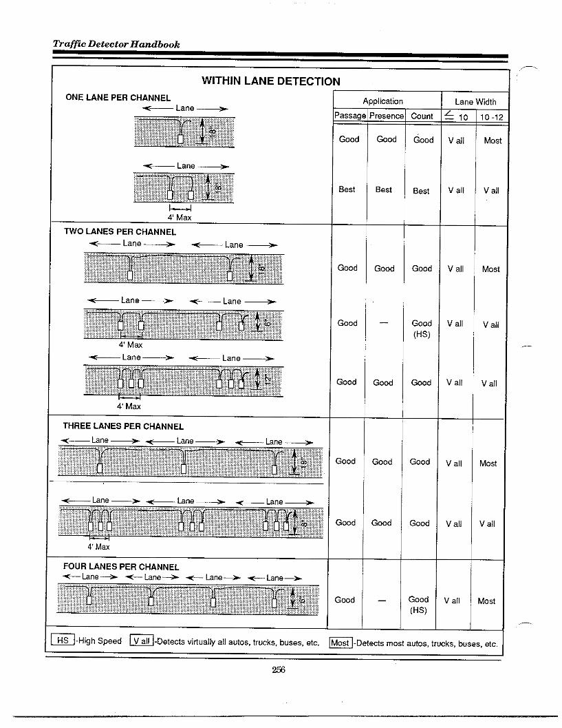
Traflc Detector Handbook
~-High Speed ~-Detects vitiually all autos, trucks, buses, etc. m-Detects most autos, trucks, buses, etc.
m
,—
.—
—.

Appendti L
P
WIDE LANE DETECTION
WIDE LANES
17,-IN >
I—.4—4–IMax Max
16-.7A, .
Max Max
TWO WHEEL VEHICLE DETECTION
ONE CHANNEL PER LANE
- ,8
Max Max
< Lane 10 Mm _
l—~12” 30”
MU Max
WO CHANNELS PER LANE
Lane 12 Max ~
—1 l—l~ I&Max Max
A
‘assage
Gwd
Good
]Iicatior
resent<_
Good
Good
Count
Good
Good
Lane Wdth
: 16-
v all
ti
:ood
2ood
Best
)Iication
:esenm=
Best
;0unt
;ood
Good
(HS)
Best
Vet
Bikes
Most
jome
V all
16-24
V all
!s
C an<age!
4 all
v all
Mos
~-High speed ~-Detedsviflually =lla”tos, tr”~s, buses, etc. B-Deteds most ~“t.s, truck., buses, et.
IJ i

~afic Detector Handbook
.—..
LEFT-TURN LANE DETECTION
WO CHANNELS PER LANE
THREE CHANNELS PER LANE
1“~4U
Detection Zone
IProbes 18 deep
I J~:Pl
b60
Detetiion Zone +
Probes 18“ deep
1<7V
Detetiion Zone+ 32 1/2
,.All Probes 1W deep
Number
of Probe
6
8
10
9
>plicat i
Front
V all
!ost M(
& V all
lost M(
A V all
V all
Detetiion
Zone
Most
Most
Most
=-Highspeed ~-Detects viti”ally all autos, trucks, buses, etc. m-Deteds most autos, trucks, b.ses, etc.1

APPEND~ M.
C~CTERISTICS OF LOOP F~URES
During the 1980’s, a number of studies were cOn-ducted to detemine the frequency and cause Ofloopdetector failure and to define the factors that con-tributed to such ftiures. me underlying pu~ose ofthese studies was to identfy possible solutions thatwodd increase reliabdity and life expectancy Ofloopdetector installations. A number of these studiesinvolved tisting of various 100Pconfigurations andselectsd matarids in agency facilities. None ofthesepafiicular studies, however, tasted dl possible con-figurations or dl avaflable materials or products.
SUR~YS EVWUATED
Four studies were patiicdarly significant in that,P. they contained the results of sumeys, consisting of
questionnaires and interviews, covering the expedi-ence of numerous agencies. These studies, identi-fied below, are summartied in this appendk
.
.
.
.
,-
ImprovingMateriaZe andMethodsfor Installing Loop Detectors.F~A-OR-RD 88-03. OregOnDepati-ment of~ansportition, 1986 (OregonStudy).
Evaluation of Inductor Loop In-stallation Praeedures in FlmiblePavemnts, WA-RD 76.I,Universityof Washington, 1985 (WashingtonStudy).
Study of Wafic Loop Faizures,FHWA-MN-RC-84.04. MinnesotaDepartment of Mansportation, 1984(Minnesota Study).
Evaluation and Improvement ofInductive Loop Detectors, F~AResearch Report No. 119, New YorkState Department of fiansportition,1985 (New York Study).
O~GON ST~Y
This study was desiWed to: identify causes of 100Psystem faflures and methods used to remedy prOb-lem areas through a sumey of selectid state and10cd agencies; assess the accumulateddat% and testthose materials and procedures that appear mostlikely to be effective in the Oregon state system. TOobtain the necessa~ information, a lengthy ques-tionnaire was distributed to the following stateDOTS:
● Aaska
● California
● Idaho
● Montina
● Nevada
● @egOn
● Utah
● Washi@On
SUR~Y~S~TS
Mthowhdifferent matirials and installation meth-ods were used by the various agencies surveyed, twomajor problems associated with IOOPfailure wereconsistently repotied: 100Psealant faflure (1OSSofadhesion), and pOOrinstallation *chniques (e.g.inadequately clemed or dried sawslots). bothermajor problem common to many agencies was tirebreakage due to asphalt pavement deterioration.me City of Nbany, Oregon cited pavement flexingand shoving which caused the epoxy sealant to POPout of the saw slot necessitating resealing. ThePortland Metro Region had many problems in 100Pfailure due to road wear down to the 100P tireprimarflyin wheel rut locations. Many agencies alsoexperienced 100PIOSSdue to trenching for the insta-llationor maintenance of under~ound utflity lines.
259

Trafic Detector Handbook
.—
Of patiicularinterest is~aska’s exclusive use of theprefomed 100Pfor all of their roadway installedvehicle detection. Their prefomed 100Pis composedof # 12 AWG cross-linked polyethdene wire encasedin one-inch, schedde 80 PVC conduit. The 100Ptireis placed in the conduit, which is then assembled totbe specified 100Pdimensions. Naska reports no100Pfailure using this system of prefomed IOOPS.Other States also reported the selected use of pre-formed 100PS.Oregon uses prefomed 100PSmostlyin signalized mavel or dirt detour areas aroundbridge construction sites. California and Utah haveexperimented with preformed 100PS and haveachieved satisfactory petiormance with no 100Pfafi-ures reported.
Table M-1 presents a summary of the suwey re-sults. It should be noted that with the exception ofthe State OfUtah, most of the 100Pinstallations areperfomed by contractors.
CONCLUSIONS W ~COM~NDATIONS
Previous to this study, the Oregon vehicle detectionsystem consisted of a 3- x 3-ft (0.9- x 0.9-m) diamond100P,constructed with four turns of Tm wire.The 100Pwas installed in a V4-in (6.5-mm) wide sawcut and encapsulated in apreappmved sealant. Thesplice between the 100pwires and the lead-in cablewas made as close as possible to the 100Pand was SO1.dered, covered with heat shrinkable tubing, andencapsulated with sealant. The lead-in cable (BeldenNo. 8720) was installed in the sawcut from the 100pto the curb or edge of pavement, and then in aconduit under~ound to the controller.
Based on the research study results, Oregon hasamended many of their specifications and practices.They continue to specify a 3- x 3-ft (0.9- x 0.9-m)diamond cOnfiWratiOn when the 100PSare in seriesin the field. However, any single 100ps are nowrequired t0be4x4ft(l.2x 1.2m). BackerrOdtOhOlddown the 100Pwires is now specified on all stateprojects. A signflcant change is that the splicebetween the 100Pwires and the lead-in cable is nowmade exclusively at pullbox locations.
Presence loop confi~ration evolved to its present
specification in order to accommodate the occur-
rence of smaller vehicles in the traffic stream. TWO3-x 3-ft (0.9-x 0.9-m) diamond 100PSare connectedin series. A single 4- x 4-ft (1.2-x 1.2-m) dtimond isplaced upstream to provide a long loop effect. Infor-mation from this detector is input into a separatedetector channel so that the Model 170 controller“carry-ovefl feature maybe used.
Presence type operation is used on left turn lanesand most side streets. LOOPspacing is now 4 ft, 12ft, and 60 ft (1.2, 3.6, and 18 m) from the stop line asshown in Fi@re M-1.
Hgure M-1, Presence loop configuration.
Because of the incidents of sealant ftilure, 16 seal-ant products were tested on both asphalt and ce.ment pavements. Sealant installation was made inJuly 1983 and was continually obsemed untd thespring of 1984.
The sealant was subjected to a cross-section ofweather. Jdy, AuWst and September were verywarm and in December, snow and freezing conditionwere present. Cold and wet conditions continuedthough the winter months. Ten of the sealantstested were approved and added to the approvedproduct list. It was recommended that testing ofvarious epoxy sealants be continued.
Oregon State maintenance personnel expressedinterest in enclosing the 100Pwire in a V4-inch vinyltube ptior to placement of the tire in the saw slot.While it was detemined that this itim was worthyof consideration, the State expressed concern aboutthe need for a wider saw slot and extra sealant andthe requirement to ttist the 100Pwire 4 to 6 turns ‘per foot from the 100pto the pullbox.
260
—.

&pendti M
Table M-1. Oregon suwey results.
I Percent Installed byState State &ntrador
I Alaska ‘a’OrFaiures +1No loop failures repotiedExcluslve use of praformed loops
~ ,deho 1+ :California
Improper seahng and Uses preformed loops in pwrforiegn matarial in saw slot pavement and din detours
90 Improper sealingNo failure for loops made of #
20002 cable
\ Montana i 10 I 90 I improper saahng
Nevada
Oregon :0 L “zz~ 1 ~ 1
Utah 70 Impmperseahng and Used some preformed loopswith,. no failures
I Washi”gto” 10: I fEn~:~C~Ot I
Nead better inspetiion to improve1000 oarformance
It was evident, from the State experience and fromthe gathered data, that complete cleanout and dry-ing of the 100Psaw slot is tital to long lasting, effec-tive 100Ppetiormance. The Stite became interestedin the saw cut cleanout nozzle developed by the Stateof New York. This nozzle uses the ‘%enturi” prin-ciple to supply pressutied water for cleaning outthe slot der sawing. A nozzle was fabricated by theState based on the New York design. Valves wereadded to control both air and water feed lines so thatthe option was avaflable to use air only, water only,or an air/water mtiture. This nozzle is being used in100Pinstallations by three of Oregon’s five regions.They report a better bonding of sealant to the sawslot due to the more efficient cleaning of the saw slotby the nozzle.
WNH~GTON ST~Y
This studv was conducted by the University ofWashingt~n CitilEngineeringDepartment and-wassponsored by the Washingtmr State Department offianspOtitiOnWSDOT) incooperationtith HA.The pu~ose of this research was to identify thetypes and frequency of 100Pdetector faflure and toidentify possible solutions. Specifically, the studyfocussed on the reasons for 100PSbecoming dislodged
,-. from the saw slot, the frequency of failure, theoptimum products and installation techniques.
The information base for the study consisted of aliterature search and aStite and national telephonesurvey of trfilc engineers. A questionnaire wasdeveloped for the survey that could accommodateeither verbal or written responses. The sumeyparticipants represented 23 cities and 7 countieswithin Washington Shte, 6 districts of the WSDOT,and 9 other Stite agencies representing geo~aphiccress section of the count~. It was noted that manyof the State and local agencies did not maintainprecise documented records related to detector%accordingly, respondents were asked to provideestimates as necessa~. As a restit, much of theinformation obtained must be considered qualita-tive.
S~~Y~S~TS
The number of loops within the respOndlngjursidic-tions and the corresponding ftiure rates are giventhe Table M-2. me tities and counties within theState of Washington had the same median numberof 100PS,while the WSDOT districts had a much~eater mean, median, and range for the number of100PS.County officials reported the lowest incidentof IOOPfailures. The WSDOT districts and ciflesseemed to have relatively comparable faflure rates.Out-Of-Stite respondents reported muchhigherfafi-ure rates than those reported in the State of Wash-ington.
261
.—

fiafic Detector Handbook
—
Table M-2. Washington State suwey results.
WI FailureRate
I Loops I O/.per year
tities (23):Mean 477 4.1Median 300 2.4Ranga 1724 11.7
Counties (7):Mean 646 3.4Median 300 1.7Range 2090 9.5
+
WSDOT Distrids (6):Mean 1255 3.6Median 525 3.0Range 4070 9.0
Out-of-State (9’):Mean N/A 11.3Median NIA 9.0Ranga N/A 34.5
‘ AZ, FL, GA, IL, MS, NE, NC, PA, &TX
The majority of the responding agencies felt thattheir loop failures were not excessive. ThOseindicat-ing excessive failures complained that repair proce-dures were very costly and that 100Ppefiomanceneeds to be improved.
Wken asked how failures were deteckd, the surveyshowed that for Washington cities, notification of100Pfaflure was primarfly from individuals outsidethe traffic department (i.e., the general public, po-lice, other agencies, etc.). For the WSDOT distfictsand county agencies, most failures were discoveredby their own personnel.
In the case of WSDOT, this is a result of their 12inspections per year of each installation. Out-Of-State agencies reported that failures were most fre-quently identified by sources outside their respon-sible depatiment.
Pavement failure was frequently identified as thecause of 100Pfailure. Cracking was listed as theprimary mode of pavement distress, whale perma-nent pavement deformation (rotting and shoting),or a combination of this with cracking was alsoreported as a primary reason for 100Pfaflure.
kplfier faflure as defined by respondents rangedfrom lightning damage to the need for constintiyretuning older models ta adjust for temperaturechanges. Other respondents stated that, althoughretuning was occasionally necessary, it was notconsidered to be a “faflure.”
The questionnaire asked what methods wereused tomonitor detector 100PS. The answers were categO-rked as follows Periodic inspection, wait for cOm-plaint about atr=lc signal, continuous monitoring,or a combinatirm of the above. Pefiodic inspectionswere the predominant method with periods rangingfrom 1 to 25 times per year per installation. Con-tinuous monitoring was used by some agenciesparticularly in areas of high congestion in order tooptimke traffic flow.
When asked who instilled the loops, approtimatily90 percent of the installations were pefiomed bycontractors. Only one State DOT indicated that 96percents of its 100Pinstillations were accomplishedby in-house personnel.
,—
Most of the cities and counties within Washin@OnState cited WSDOT specifications for loop detectors.The 100Pshape of preference was the square 100POrquadruple. Very few agencies spec~led rectan@-Iar or diamond 100PS.
Out-Of-Stiti agencies specfled a variety of 100Pshapes including the chemon. The quadmpole wasgiven the highest ratings for sensitivity and reliabil-ity. Square and rectangular 100PSscored high on re-liability but somewhat less on sensitivity. Most sen-sitivity problems were associated with vehicles hav-ing a high ground clearance such as logging trucks.Most agencies expressed some concern for the detec-tion of light vehicles such as bicycles and smallmotorcycles.
The preponderance of agencies used only pressur-tied air to clean out saw cuts. me use of highpressure water followed by pressured tir is seldomused. The reasoning cited for this was the need forthe cuts to be dry prior to the placement and sealingof the 100Pwire.
The choice of loop wire was fairly consistent among -the agencies sumeyed. Mthough the Shte spetifies# 14gauge wire with RHH-RHWinsdatiOn, many of
262

&pendm M
the city agencies prefemed #12 THHN orTWN wire.Out-of-State agencies were about eqnally dividedbetween #12 and #14 gauge tire.
The methods and products used for sealing the sawcuts and spfices varied considerably. Many of theagencies within the Stite used the WSD~ specifi-cations for sealants. Some of the city agencies usedeither polypropylene rope or cotton rope on the topand bottom of the wire to prevent the wire fromfloatingto the sutiace. (Cotton rope was substitutedfor the polypropylene rope as the polypropylene ropetends to be deformed when covered with hot asphaltforcingthe rope out of the slot. Most of the WSDOTDistricts use roofing asphalt as a sealant, whtie out-of-State agencies tended h use commercial sealantsthat had been tested and approved prior to their use.For splicing, more out-of-state agencies used sealantkits antior heat shrink tubing tith sflicone sealerfor their splices than agencies tithin the State.
CON~USIONS AND ~COM~NDATIONS
The failure rates repotied hy Washington agenciesweremuch lower thaa repotied by Out-of-StateDOTSand in the literature. The largest single factorcontributing to 100Pfailure appears to be pavementcracking. The next most impotiant factor was break-ing ofloop wires due to utility repair or construction.Other siWflcant factors include poor inspectionprocedures, pavement rotting, and sealant failure.
Problems associated tith the electronic unit can beattributed to the inabdity of these units to adjust totemperature changes and to moisture or otherchanges within the 100Pwire or lead-in cable. Thiscan be resolved by purchaing self-tuning amplifiersand by complete encapsdation of the 100Pwires.The study recommended that rope to hold down wirebe eliminated.
Much concern about the poor q~lity ofinspection ofloop installations was expressed by WSDOT dis-tricts. It was pointed out that the best remedy forpoorinspectionis training and experience. fiainingmay be accomplished on-the-job by assinging newinspectors to more experienced personnel or throughformal classes. Inspectors must remain in their jobslong enought to be effective in the enforcement ofspecifications.
It was also suggested that forms and proceduresshoddbe developed to track 100ppetiomance. Suchrecords would provide valuable ifiormation on theexpected life of 100PS,fafiure rates, faflure modes,quality and reliability of products, etc.
Finally, it was recommended that self-sealing heatshtik tubing should be considered for splicing wires.It is used quite successfully in the marine industryin deep undemater applications and adds extrastrenti and abrasion resistance to the area of thesplice. Heat ~ns tith freed temperature headsshould be used with the temperature selected toavoid damage to the wire coating.
M-SOTA ST~Y
The Minnesota Deptimentof~anspotitiOn’s ~ceof ~afic Engineering had determined that 14 per-cent of their si~al maintenance time was spentrepairing 100Pdetectors because of poor installationprocedures, pavement deterioration, or the environ-ment. Consequently, tie State Hlce of Researchand Development as asked to conduct a study toidentify the reasons for 100Pdetector failure andwhere within the installation the failure usuallyoccurs.
A literature search revealed that Minnesotis prOb-lems are not utique-loops instdledby other Statesin the snowbelt area are also tiected by moisture,100Psealantftiure, and pavement cracks andjoints.A suwey questionnaire fom was developed anddistributed to dl the snowbelt States (all Statesabove 36 de~ees latitude were considered in thesnow belt region). The District of Columbia andProtinces of Canada were also included as were themajor City and County agencies tithin the Minne-sota.
Completed sumey forms were received from 26States, two Counties, two Cities, and three Prov-inces. The questionnaire covered two critical areasof interest: reasons why the 100Pdetector fails, andthe materials and procedures used by each agencywhen installing 100pdetectors. In addition to the lit-erature search and the survey, MtiDOTs personnelwere obsemed making 100Prepairs.
263
—

~a~c Detector Handbook
.-
from anititialretiew of the completed questionnaireit was clear that most states, including Minnesota,did not keep good records concerning reasons forfailure. Characteristically, ifit was determined thata short or open circuit had occured in the loop wire,no investigation was made as to where or why theshort wasthere. Theloopwire wassimplyreplaced.
It was learned that many failures occumed becauseof broken wires or deteriorated insulation at con-crete pavement joints, pavement cracks runningthrough the 100p,or at the pavement intetiace withacurb or shoulder. InadditiOn, failures frequentlyoccured in pdl boxes were the 100Pwires are splicedwith thelead-in cables. Only one agency indicatedthat they did not make their splices in a pull box.
Splice failures occur because of comosion, moisture,orpoor connecting methods. Anumher of problemsoccurred with the ‘T formed between tires heldside by side as their ends were twisted together.Soldering was favored over crimping whfle someagencies ctimpand then solder. Many Oftheagen-cies sealed their connections with a waterproofingagent andthen wrapped with tape. Other agenciesencapsdate the connections in an epoxy or other slotsealant using drug store pill boxes Orpaper bags toserve as inexpensive molds. Commercial sealingkits were also used.
Another problem frequently mentioned was detec-tor faflure caused when older models of amplifiersbecome de-tuned. Deteriorated wire insulation,poor splices, temperature changes, moisture, vibra-tion, electrical stems, and tire movement all con-tribute tothistype of failure. Many agencies havealleviated this problem by using digital self-tuningamplifiers.
As for wire type, 25 agencies used #14 AWG tire fortheir loops. Stranded tireisdwaysused, and TypeTHHN and Tm is favored for initiation. Elevenagencies enclose the insulated wire ina thin vinyltubing which creates a conduit effect and protidesadded protection, and three agencies are experi-meriting with this concept. This tube encased wireis commercially available or can be made up in-house.
For sealing the saw slots, 12 commercial brands ofsealant were mentioned as well as many types ofepoxy and polyester resins and unspecfled asphaltcompounds. Experience andptice seem to be thecriteria used in making a selection.
The question of most concern in this study involvedthe way the various agencies installed their traffic100PS.Theresponse indicated three particular pro-cedures were most important in installing loops:laying and sealing the 100Pwires, addressing the100Pcomers, and crossing expansion joints or pave-ment-shoulder joints.
The evolution ofM~OTprocedures used to lay andseal the 100PSwires proceeded from merely insertingtheturns ofinsulated wire in the slot and sealingwith any type of inexpensive sealant. It was soonlearned that these inexpensive, untested sealantswere unsuitable for preventing water and foreignmatetialsfrom entering the slot. Thesealantwouldeither loose its bond with the sides of the slot orwodddeteriorate tothepoint where it would just _,disinte~ate. Foreign materials entaring the slotcould pierce the tire insulation and allow moistureto come into contact with the loop wire thus causingdetuning or possibly a short.
~is led to the testing of various sealants h find asealant that will maintain adhesion to the side of theslot dutingexpansion, tithstand compression whenjoints are contracting, and yet be of the right tiscos-ity to be poured inti the slotbut not mn out ifthe slotisonanincline. Italsobecame apparent sharp edgesalong the slot edges andatthe loop corners couldalso create breaks inthewireinsulation. Therefore,it wasdetermined that thesha~ edges should besmoothed and the debris flushed from the slots withpressurized water and then blown drytithcom-pressed air.
Sharp bends at the 100Pcorners were reduced bycutting 45 deWee diagond slots. However, thismethod created triangles at each corner that couldeventually break down from the wheels of vehiclespassing over the area. Several agencies covered thisproblem by drilling 1- or 2-in (2.5- or 5. l-cm) holes ateach corner instead ofcutting the diagonals. The --corners of the hole are then chiseled out h removethe sharp edges. Other agencies didnotdrfllholes
264
,.,..

at the corners; rather, they chisel out the inside ofthe corner ta weate small open trian~lar areas.Whether they drill holes or chisel, to accommodateany movement of the pavement it was stressed thatslack in the wire shodd be left at each corner.
Many ideas have been presented on how to fll theslots and corners with sealant. Some agencies sim-ply lay the wire in the bottim of the slot and fill withsealant, hoping that most of the wire will be encased.In an effort to better encapsulate the wire, otherspartiaRy fdl the bottam of the slot with sealant, laythe 100pwire, and then add more sealant until it isalmost flush with the top of the slot. StiR otheragencies go to the trouble to put sealant in thebottom of the cut and between each turn of the loopwire before find sealing to achieve total encapsula-tion.
TOcreate a condtit effect without the need for widesaw cuts, some agencies choose to cut a shndardslot, lay the tires, and then wedge a form of rope inthe slot over the tire before adding sealant. This
,-. procedure dso reduces the amount of sealant needed.
One agency suggested that this method createsproblems in that the rope is not as resflient as thesealant and that voids occur between the wires andrope andor the slot. A condtit effect can be achievedduring asphalt pavement construction by cuttingthe slots and inserting the wire before adding thefinal layer of bituminous asphalt.
Rigid plastic tubing (PVC) is used as conduit forprefomed loops by a number of agencies. This V2-to l-in (13- to 25-mm) tubing is often installedduring constmction before the final courses are laid.However, if it is used in an etisting installation,much wider cuts must be made h accommodate thetubing, thus weaking the pavement structure.Experience has demonstrated that preformed 100PSare particdarly effective where the pavement isbroken or in poor condition.
CONCLUSIONS AND ~COM~NDATIONS
MtiDOT contracts out the installation ofnew trafficsi~ds, ramp meters, and automatic tr~lc count-
,- ers, all Ofwhich use 100Pdetectors to activate thesetrtilc control devices. Inspection of new instiga-tions isprefomed by MtiOTinspection personnel.
Repairs or replacement offafled loops are pfimatiyaccomplished by M@OT maintenance staff.
It should be noted that previrmsly, M@ot did notrequire its in-house crews to follow the same proce-dures and Stite specifications as those required ofa contractor. For example, the contractor is requiredto place a layer of sealant in the bottom of the slotbefore installing the 100Pwire, while MdDOT crewssimply lay in the wire and cover with sealant. Inaddition, in-house crews use #14 AWG wire insteadof the specified # 12AWG. However, MdDOT forcesuse insulated tire encased in a thin tiny] tubing,which is not reqtired of the contra~or.
It was found that there were occasions where theMtiDOT crew created their own problems by choos-ing poor locations for the new loops or routing thelead-in wires through areas already showing dis-tress. Moreover, they do not follow spec~lcationsregarding expansion joints, cracks, or pavementedges.
Based on this study project, their primary recom-mendation was to ensure that the procedures usedby MtiDOTs repair crews be consistent with thoserequired of the contractor in installing anew 100P.Itwas dso recommended that effort be directed ti-ward achieving consistency between each crewmaking repairs. Using MflOTs standard platesas ~idelines, it was suggested that the repaimenmeet and decide how future repairs wodd be made.The major points to be covered include:
.
.
.
.
.
.
Depth ofloop saw slots and steps b betakenti ensure that a consistent depthis maintained.
HOW100Pcorners are b be treated.
Size and type of conductor used forloop wire.
~eatment ofpavementjoints or crackpassing though the 100P.
Procedures for inserting and seafingloop wire.
%oceduresforsplicingand wate~roof- :ing splice.
265

fiafic Detector Handbook—
A significant portion of the 100Pfdures experiencedin the State was attributed to poor installationprocedures by the contractor. Poor inspection proce-dures contribute to these failures. It was recom-mended that the M@OT inspectors become moreknowledgeable in the proper instillation of traffic100PSand conduct more ag~essive inspections dur-ing installation.
A major conclusion evolving from this study wasconsistent with other sumey findings: records anddocumentation of loop failures throughout the coun-try are wholly inadequate. It is common practice tosimply replace a failed 100P instigation withoutinvestigating the cause of failure or the precisemechanism of ftiure. It was concluded that de-tailed itiormation on 100P ftilures is critical todetermine the most appropriate procedure or prod-uct that would enhance reliability and 100P lifeexpectancy.
TO resolve this inadequacy, M~OT has recom-mended that d] new 100P installations be docu-mented and stored in a computer pro~am. Initialinput would include type and stie of wire, model ofelectronic detetior unit, sealant used, identity ofinstaller (contractor or in-house crew), etc. Thisinstallation would then be tracked throughout itslifetime tith SDrepairs fully documented.
A new repair sheet wodd be developed that wouldinclude a check-off list for use during trouble shoot-ing and dettils on reasons for faflures and on repairsmade. Ml replaced eqtipment would be identifiedand input into the computer for future reference.
~W YOW ST~Y
This study included an indepth survey of nine NewYork State DOT re@Ons responsible for over 15,000100P installations. Mthough this study did notinclude a survey of Out-of-State agencies, severalState DOTS were contacted relative to the types ofsealants used. The study was initiated after a 1980study determined that up to 25 percent of New YorkState’s 15, OOO1OOP detectors were not operational at
any given time. It was further determined that 100P
detectors were maintenance-free for an average ofonly2 years. Consequently, this study was desi~edto find the major causes of 100P faflures and toidentify steps b reduce the frequency of fafiure.
Al cument loop failures in the State were listed anda number of instillations were inspected to deter-mine ifactud causes offaflure were readfly discern-ible. In most instances, faflures were attributed bone or more of the following factors:
.
.
.
.
.
Design and installation oversights.
Sealant faflure.
Wire fnilure.
Various types of pavement ftiure.
Utility constmction activities. ,.—.
An evaluation sheet was designed to record failuretypes during the full-scale investigation. A total of340 failed 100PSwere folly documented and so~dinto various categories of major ftiure type. In allcases, final faflure was due to a broken or Woundedwire resulting from installation emor, materialproblems, or other d~lctities.
Of the smeyed 100PS,40 percent had exposed wires,and 20 percenthadbroken wires. Broken or exposedwires were attributed to three major causes: sealantfailure, pavement fnilure (cracking, potholes, andshoving), and tire float. About 50 percent of theftiled loops that were examined had patiid or com-plete sealant faflure.
It was determined that when the sealant did notachieve a good bond to the sidewalls of the slot,debris and water codd infiltrate the slot. Thesealant can then be forced out of the slot, exposingthe wire to traffic and inducing 100Pfaflure. MOis-ture could also enter the slot and create an electrical~ound. Once moisture entsred, expansion andcontraction of the water during freeze-thaw cycleswodd futiher disrupt the 100Pand abrade the insu- —lation, exposing the wire to an eledrical mound.
266

The most frequent pavement fdure tiecting the100Pwire is cracking. In general, pavement failurecauses tie 100Ptire to be strained resulting in tirebreakage, wire insolation were, or the infdtration offoreign materials. Of the failed 100PS,50 percent oftheAC and asphalt-overlaid PCC sutiaces displayedsome cracking.
LOOPSin PCC without overlays represented only 20percent of the cracking failmes. However, this typeof pavement presents other problems: woss slab
Table M-3. New YoW suwey results,
Failures i%
1-
Numberl 34o
“’centkiurface Cracting
Major 18
Minor 29
z:None Wsib[e 53
Pavement Heaving
Wsible 10
None Wsible 90
Pavement Patching
Patched I 14
No Patching 1 86
Sealant bss l—Patiial 1 35
Total 1 23
None E
Loop Wre Wsible
Wsible 39
Not Wsible 61
Broken Loop Wre l—Broken I 22
ed Loops, percent
TVDe Of PaVemOnt *
AC
275
81
20
30
COmp
20
6
20
40
40
0
100
20
80
10
30
60
35
65
None Evident I 76 1
k AC= Asphalt pavementtimp = Asphalt overlay on concrete pavementPCC = Concrete pavement
n
Pcc
45
13
2
20
78
0100
9
91
11
38
51
36
62
29
~
movements that strain the wire at the pavement-shoulder intsfiace, or where 100Ptires cross j oints.Table M-3 presents a summary of the suwey resdtsby types of ftiwes for each type of pavement.
CONCLUSIONS ~ ~COM~~ATIONS
This extensive examination of failed loops revealedtwo major areas for further study—sedant reliabil-ity and reduction of wire breakage due to pavementfailure. This sumey also led to the conclusion thatproblems existed in the installation process,
Some fded wires were found ve~ close the sutiaceeven when the sealant had adequate adhesion to thesidewalls of the slot. It was concluded that the tirehad floated to the sufiace either before the sealantcodd cure, or because the sealant remained plastic.
Oninspectionofvarious splicingmethods and mate-rids used in the pdlbox, it was found that differenttechniques were applied depending on the indlvid-ud doing the splice. TO@arantie waterproofinginte~ty and longevity of the splice, better tech-niques should be evaluated and the best methodsinco~orated into a statewide standard.
~er a thorough investigation of various install-ationelements and procedures, the follotingchangeswere recommended:
.
.
.
.
Use encased 100Ptire (reqtires a 3/8-in (9.5-mm) slot instead of V4-in (6.4-mm).
Chip or core corners of loop sawcutrather than diagonal cuts.
Use cold-applied sealant. Hot-asphaltsealants have proved less effective andcan cause severe damage to wire insu-lation.
Use a higher horsepower saw for thesawcut (18 hp or higher) and use waterwith sawing operation.
261

~aflc Detector Handbook—.
● Assure saw slot is properly cleaned ● Standardtie instillation techniques,and dried before application of seal- make sure that the work force is fullyant. aware of these standards, and that
specifications are rigidly enforced on. Assure that appropriate holddown both the contractor and the agency.
materials are used and properly aP-plied. ● Continue evalwtionto determine best
● Use proper splicing techniques.currently available methods andmaterials.
—
.—
268

r
@
Mlnlst~ VOLUME 1-ofTra~titlon
ELECTRICAL DESIGN MANUALOnho PART 2- COMPONENT DESIGN
Chapter 9
Grounding

-affzc Detector Handbook
-.
Chapter 9 Tableof Contents
Wfiin I Reasons for Grounding Page 3
l.~e~Grounding . . . . . . . . . . . . . . . . . . . . . . . . . . . . . . . . . . . . . 3
2S@emGrounding . . . . . . . . . . . . . . “’”~
3.tightningDMharge . . . . . . . . . . ““’’’”
=tin II Cakubtion of Resistance to Ground Page 5
l.General . . . . . . . . . . . . . . . . . . . . . . . . . . . . . . . . . . . . . . . . . . . . 5
2.%tlResiWlvm 6
3.GroundElectrodeReQstancetoGround .8 —.
3.1 GroundRads . . . . . . . . . . . . . . . . . . . . . . . . . . . . . . . . . . . ...8
3.2Pedestals . . . . . . . . . . . . . . . . . . . . . . . . . . . . . . . . . . . . . . . .
3.3PlateElectrodes . . . . . . . . . . . . . . . . . . . . . . . . . . . . . .
3.4WtreGrids . . . . . . . . . . . . . . . . . . . . . . . . . . . . ~~
3.5MuMpleRods, ..,...,: . . . . . . . . . . . . . . . . . . . . . . . . . .
3.6ComMnOflanROd&WreGnds . . . . . . . . . . . . . . . . . . . . . . . . . ...16
3.73ngleWire . . . . . . . . . . ‘“’8
3.8SummaWofColcul@ion:, . . . . . . . . . . . . . . . . . . . . . . . . . . ...19
39Applictiion . . . . . . . . . . . . . . . . . . . . . . . . . . . . . ..j~
3.10Problem,Areos, ..,...... . . . . . . . . . . . . . . . . . . . . . . . . .
311A pplicahonGutdellnes. . . . ‘“26
~tfon Ill Eff~ts of Ughtning Page 28
l.General . . . . . . . . . . . . . . . . . . . . . . . . . . . . . . . . . . . . . . . . . . ...28
2.DeQgnCnteria . . . . . . . . . . . . “’’”’’’”” “29
Vo-1-ElecMcal ~nManuOl 9-1 ‘“Pafl 2- ~mpa~t bdgn ~em~, 1989
270

Avvendti N
3. Power Surges .,, , .,, ,,, ,, .,, ,,, ,, ..,,..,,,,,.,,...,.. ,.29
4.~herhurcesofPossibleDamage ,,, , ..,..”,....,,,,., ., ..,,,.,,32
Sfion IV Summaw of Msign guidelines Page %
l,Tr~cSignatSystems, .,,, .,.,,,,,.,....,,,, ,, .,, ... . . . . ..M
tifion V References Page 37
-’9-2 volume 1- EIw~cal D~n MnMlWa@, 1989 Part 2- Corn-t k~gn
271

fiafic Detector Handbook
.-
W@nS br Grwnding *Mn I
1. Sofefy Grounding
(1) Grounding of all metillic electrical enclosures is required for safety. Ifa live conductor tiuches the me~l, a large ‘shoti circuit cument’ flowsb Wound thus tripping the circuit breaker. If the metal were notWounded, it would assume the same vol~ge as the touchingconductir and remain so until discharged @ ground. Men touchedthe discharge could be through the person’s body @ Wound dependingon the resistance of gloves, boots and the material the person isstanding on.
2. System Grounding
(1) A low voltage system is wounded throughout@ ensure that anyline-to-wound fault is cleared by the circuit breakers prior b doing “any pemanent power system damage such as melting of cables etc.The systems ground is usually tied to the safety ~ound, If the twomounds are separate the following disadvantages occur
(a) ‘Resistance to wound of both system and safety ~ounds isneater than would be the case if the two were connectedtigether.
(b) High currents could still flow in the safety ~ound in theevent of cable insulation failures in the enclosure.
(c) A high de~ee of coupling, through the eatih, is dificult bavoid if the pound rods are in the same local area.
(d) mere decoupling is possibIe, voltages (otin dangerous) canbe possible between the nearby ‘qounded points’.

3. Lihtning Diwharge
(1) Li~tning induced curre”t~ On ~ab]es must& Ave” ~ fast a“d ea~v--path to wound thro~h protective detices such as lightning amesters,varistors and gas-tube arresters. If the path b mound is not providedproperly the voltige surge ‘spikes’ and resulhnt cument and ene~will damage components. Electronic components are partialarlysuscepbble b damage since they operate at ve~ low vol~es andhigh speeds and are not desi~ed h physically absorb my signifimntener~.

-afic Detector Handbook
~lwla~on of Resistanos to Ground *m 11
1. *neral
(1)
(2)
(3)
A minimal resisknce b wound is desirable. Older versions of the
Cde called for 10 Q maimum b ~omd. This requirement is now
replaced with a description of the physical wounding materials, or, inthe case of a substation, limiting the vol~e rise, due ~ a fault, w5~V. The requirement for 10(2 was dificult ti design and perhapseven more dificult to obtiin during ins~llation.
The resistance w Wound depends on several non-exclusive factirs:
(a)
(b)
(c)
(d)
(e)
(f)
The numkr and length of wound rods
The number and length of connecting ~ound wires in thewound ~id
The quality of wiring connections
The resistivity of the earth
The temperature of the earth
The water contint of the eatih
The last three factirs are somewhat weather dependent and aretherefore beyond precise desi~.
..—,
274

Appendti N
,m.
(1) The resistitity of the soil, at the site under consideration, is ameasure of the resistance to conducting electrical cument and ismeasured in ~ (ohm-metres). &presentative values are @ven in~ble 1:
I Soil ~ I Wsistitity ‘p’ (Qm)
Clay, Saturated Silt 100
Sandy or Silty Clay 250
Clayey Sand OrSatura@d Sand 500
Sand 1500
Gravel 5000
Dv Sand, hck >5000
Table1. Representativeualuesof &ii Resisticity
(2) The soil classification and p values in Tablel are left purposely vaguesince environmental effects can drastically change the resistivity ofthe sail. Table 2 shows the typical variation of a nominal msistititywith different soil temperatures:
9-6k~. 19s9
VOluma 1- EIWMCOI -n MonmlPan 2- COm~t @Sgn
275
—

fiaflc Detector Handbook
rGround Temperature, 0° C. %sistivity (% of Nominal)
20 73
10 100
o+ 139
0. (f=ze) 303
-5 798
.10 3333
(3)
(4)
Table2. Var&nceof Resistil?itywith GroundTemperature
& wellas temperature, resistivity varies widely with moisturecontent, ranging by a fac~r of 3507;.higher for sail in the ‘dry’ s~teas opposed to a ‘wet’ stite.
In order b custim desi~ a ~ounding system, the desiaer wouldneed @ know not only tie ty-~ of soil and its resistivity but also thecondition of future measurements. For this reason, a resistivity ofp = 100 (h is selected as the basis of desi~ for grounding systems.(The system is field measured u~n insbllation and any deficienciescan bs made up by instilling supplementary facilities. It should also
be noted that On@rio has little or no lightning activity duringmonths when the mound temperature is below the freezing point. .

AppendtiN
n
3. Ground E~trode Resistance to Ground
*neral
(1) Resistance to ~ound for a single ground rod may k mlculati from:
“=R’=*[’n[*)-llwhere:
R~ = Resistance to qound in ohms
p = Soil resistivity in (> m
L~ = Rod length in metres
a~ = Rod radius in metres
RR = Resistance@ gound of one rod in ohms

~afic Detector Handbook
Example1: for 20 mm x 3 m Rod
Given p = l~h , LR=3m, aR =0.Olm
If the mil is wet and p decreases@ p = 50 M
If the soil is d~ and p increaws @ p =3- :
R.=*[,.[%]-1]= PIIt may& seen that the nominal resistance ~ ~ound of 50 Q usuallyquoted for a single wound may vary substantially depending on wiltype or conditions.
Example 2: for20mmx 6 m Rd
Given p = 100 f2m, L~= 6 m, aR= 0.01 m
or for a 100% md depth increase (over example 1), the resis~nce ~~ound is decreased by 44%.
Example 3: for 25 mmx 3 mRd
Given p = 100 fti, LR= 3 m, UR= 0.0125 m
RG=*[l.[*]-l]=FIor for a 25% increase in rad diametir (over that of Example 1), theresisknce b ~ound is decrease by 3~o.
278

(1)
Example4:
Example5:
Using tie =me formula as for a single Wound rod,
“=R”=*I”[*)-llwe have the following examples:
for Steel Footing(220mmdb. x 2200 mm)
Given p = 100 (h, L~ = 2.30 m, a~= 0,110 m
R.=*[1”(-]-l]=I=Jor 26 % %tter” than a single rod,
for Steel Footing (W mm dia. x 1S20 mm)
Given p = 100 fti, LH = 1.830 m, UA= 0.043 m
R.=*[l.[*)-l]= FI
or 12 % “wor~” than a single ~ound rod.
m

Daffic Detector Handbook
.—
General
(1) For a single plate:
“=Rp==[ln[al-llL 1
where:
Rp = Resistance of plate to gound in ohms
LP = bn@h in metres
WP = W)dth in metres
TP = Thickness in metres
Example6: for610x 610x 6 mm Plate
Given p = 100 fh, LP= 0.61 m, WP =0.61 m, TP = 0.006m
[[2~~61 ‘nRG=—
o&nlm]-l]= PI
—.
VOlm 1- Ei*Mcal D~n Manual 9-11 —Part 2. COmWmt M#gn D-e-r, 1%9

ADuendti N
Geneml
(1) For the case of a grounding syswm consisting of a wire grid only, the
tire shape forms a ground plane (similar to antinna desiw) which, if
buried deep enough, an constitute the most effeetive part ofgrounding system. (Ground rods are normally driven in any event inorder h penetrate below the frost line).
The resis~nce to ground for a grid system is approximakd by:
R.=Rw=&[In[=]+&-5.6]
where:
Rw = Resis@nce of wire @din ohms
LW = To&l bn@h of mid wires in metres
dw = Diameter of wire in metres
ZW = Burial depth of @d in meters
Aw = Plan area covered by grid in Wuare metres
9-12kern*, 1%9
VOlum 1- Elw~cal @gn ManmlPart 2- Corn-t btign

fiafic Detector Handbook
,.—
Example7:
Example8:
43 3
3
Using3 x 3 m gdd whh crostk
Glven:p = 100fh, Lw = 5x3= 15m, Z~ = 0.3m
Aw = 3 x 3 = 9 W. m., dw = 0.0105 m (#20)
[[
,n 2x 15R~=Rw=~ _1
+ 1.4X15VO.O1O5X0.3 1—-5.6 = ~~49
Ualng3 x 3 x 3 m TrtsngularGfid
Given:p= 100om, Lw = 3 +3+3= m,, ZW=O.3m
dw = 0.0105 m (#20j, AW = 0.5 x 3 x 3 sin 6@—.
RG=Rw=~
262

@nerel
(1) The combined effect of several mds is similar to the rod resistanceacting in parallel and is given by:
where:
R.WE= combined resistance of multiple rods to pound in ohms
n = number of rods
AR = Area covered by the n rods
for 20 mm x 3 m rods:
9-14k-, 1%9
Volm 1- EkMcal ~n ~1%d 2- Corn-t W9n

fiafic Detector Handbook
—
Example 9: Using Fwr Rds on 3 m ~uare
G!venp = 100 f)m, a~ = 0.01 m, L~ = 3m, n = 4
AR=3x3=9sq. m
[ 1RG=R,”,= A I + 14(’: - 1)2 = m11.7Q
(no@: rods not connectid by wire)

@nml
(1) It is maybe necessa~ to include both rod and wire @ds forsetice~ounds, substitiorss, etc.
me resistance to Wound of the combined systam is @ven by:
=
where:
R(; = Total system resistance to ~ound in ohms
RW = Resis@nce of wire @din ohms (section .4)
R.M~= Resismnce of multiple rods in ohms (section .5)
RwR = Mutual resistance factor of the wires m the rods
andI
1
for 20 mm x 3 m rods:
I [ I.ti\v~ in (0.67Lw) + ~ -4.6Rwn = ~,v II
9-16 Volum 1- EIwWcal -n ManWlkink, 1929 Pan 2- @m-t Hgn

Trafic Detector Han@book
.—
Example 10: Using 3 x 3 m Grid with CroStie & Rds
Given: p = 100Qm, L~ = 3 m, a~ = 0.01 m,
mAw=A~=3x 3=9~. m,n=4, Zw=0.3m
~ d.= 0.0105 m(#20), L. = 5x3=15m
[[)RWR=~ in ~ +%-4.61
Substituting the ~ven data in the fomula, we have:
‘~~=fi~1n(0,67x~5)+ 14x15L
T-4.6]= p]
[
1.4(\z - 1)21RM~=~ 1+~ = 11.7(2 (Example 9j
[R.=% ‘
‘“ (io::::o.3]+ * - 5’6] = 16”4” ‘Examp’e ‘)
—..
Substituting the above results in the formula, we have:
If the site soil was clayey sand instead of clay, p would be 500 ~instead of 100 ik Wable 1) and the resistance b wound would beRc= ~13x ~= 565**
> 100
—

3.7 3iw* Wue
&nersl
(1) A single wire or coun@moise directly buried in eafi has a resistanceto wound of:
[
‘[ ’nK)+’n&)-2+=-:RG= RC = 2tiw
L
where RC = Wsistice ti ground of buried mnductir in ohms.
Example 11: using * AWG Wlra
G]ven: p = 100 (h, zw = 0.6 m, Lw = 50 m, aw = 0.00252 m
Rc=&[In[&]+In[%]-2 +%-%]= F/
m

Trafic Detector Handbook
&neml Fomulee
2tiR[[=,]]Single Wd Only RG = RR = ~ In a -1
2tip[ (0.5;HTP)-1]Single Plate Only: R~ = RP= A In
WreGridOn,yRc=Rw=&[ l”[*]+~-5.6]
Multiple MS Only:
1[1
2.SLR(V; - 1)*RG=RM~=& In ~ -1+—
~A~ 1Multiple Rds & Wire Grid: R~ =
RwRM~- RFnRW+ RMR- 2Rw~
[[)
2LW law *,6where: Rw~ = ~ I“ — + --
d. LR YAW 1
2~w[[w][z.] LW i]Single W]re Only: RG=Rc=~ In ~ +ln~ -2+~-~
Were:
RG = Total resistance h wound of the system in ohms
RR = Resistance@ wound of a single ~ound rod in ohms
RP = Resistance b wound of a single ~ound plate in ohms
RW = Wsistince h ~ound of a single ground wire in ohms
R,”k = Resistance b wound of multiple ~ound rods in ohms

Append& N
*
RWR = Mut~lresistince factiroftires brtis in ohms
RC = Resishnce to floundofa single buried wirein ohms
LR = bngthof Wound rodinmetres
LW = Length ofwireinmetres
Lp = W]dthofplate inmetres
Tp = Thickness of plate in metres
AW = Area of wire ~id in square metres
AR = Area covered by several wound rods in square metres
OR = Radius of wound rod in metres
aw = %dius of wire in metres
du = Diameter of wire in metres
Zw = Burial depth of wire in metres
n = Number of ~rmnd rods
p = soil resistivity in ohm.metres
Uwful Fomu&
(1) Since the Minist~’s wounding systim uses common components of,
. 20 m dia. x 3.0 m long ground rd
. M2/Oand #6 AWG @ound we
then, the general formulae can be reduced to reflect the physicalparameters of the common itims as follows
. Single Rd Only: RR= 0.32P
n 9-mm~. 1969
Volume 1- EIwwcol D-n MawlpOd 2- corn-t Ngn

fiafic Detector Handbook
,.—.
.
.
.
.
.
.
.
.
Single 220 x 2300 M Steel Fmting RR= 0.24p
Single 85x 1830 m Steel Fwting RR= 0.36P
SlnQe 610 x 610 x 6 m Plate: ~= 0.4@
Single #6 Wre, 3 m Ien@, (ZW = 0.30): RW= 0.40p
Single #2/O Wre. 3 m len@. (ZW = 0.30): RW= 0.36p
3 x 3 m @id c/w cro~-tte, (#2/O tire& 4 rods):m=o.llp
2 Rods@ 3 m spce, wti #6 tie: %= 0.19p
2 Rb @ 3 m s~ce, wth #2/O tte: %= 0.19p
I The foregoing formulae are approximate and maybe used wherespecial conditions appiy.
(1) The Ministry’s designs for grounding systems are based on thefollowing premises:
(a) A resistance b ~ound of 10 (> should be obtained inaccordance with good practice.
(b) In ca~s where 10() b wound is impossible b obtain usingpractical methods, 25() to wound is the minimumrequirement provided that adequak s~ps are taken toensure that step and touch voltages do not present a safetyproblem to workers or the phlic.
(C) Eve~ effort is @ bs made to meet the 10 () @ woundrequirement, where practical, by addition of groundelectrodes and wire in the field.
V- 1- El*Mcal D~n ManmlWfl 2- Corn-t htign
9-21 —Dx_r, 1989
,..

(d) Since soils and their resistivity va~ widely with location andenvironment respectively, the Minist~’s stindard criteria fordesi~ is p = lW ~. The resis~nce b ~ound of thedesi~ed system is field checked and any required alterationsare made at that time. Were it is obvious b the desi~erthat increased grounding facilities will be required (sand,gavel, reck, etc.) the required facilities cm be estima@d fromTable 3 and included in the desi~.
(e) Table 3 is derived from the general formulae of sol-section3.8.
(f) The following notes apply to Table 3:
0)
Gi)
Oii)
Configuration No. 9 maybe used with the continuous #6Wound wire mmmnly uaad for lighting. Grounding ateveg 5th ple applies.
Configurations No. 11 or 12 maybe u=d for Woundingin clay or areas which remain damp. C0n6Wration No.13 should be used as the ‘stindar# desi~.
COnfi~ratiOns No. 15 to 18 indicate the resulta ofadding increasing by more tim and rods b the ~d. Ifd~ sand. ~avel or rmky areas are unavoidable, theprinciples illustrated may b extended by manualcalculation using the formulae @ven.
Values shown in brackets am for information as asimpler @d would nomally bs required.
Values shown are ‘stand alone’ values (isolated @und).An approximation of resistanm ti ground for anynumbsr of the systems, which am tied tigather withwound wire, may be made by mnsidering the values tobe in parallel.
n 9-22We*, 1*9
Volume 1- El=mcal D+n ManwlPafl 2- Comp_t bggn
ml

Trafic Detector Handbook
GroundSys@mcofi&uration
Aardi *
Sand 3Sand,lravel
p=5000~m
+
Clay Sand)aaWscnption Normal Use
Lp=p=100 200Qm h
p=
1500&
4s0
420
600
1.Single 20 mm x 3 mmd
2. Single 220x 23OOS*I Fwting
S. Single 85x 1830S~l Fmting
1610
1400
2000
2300
2050
1900
950
1400
950
800
—
I●
●
●
■
3
Addition ta System
+
32 SO
28 70Poles (~uimsadditional sysbm)
140
200
I
T40 100Poles, Cabine&(requires additional
sys@m)I
T46 115
41 103
4.610 x61O x6 mmPlate
. Single #6 wire, ham,3 m long
& Single #20 tire,bare, 3 m long
7. Single #6 tire, 2rods
1. Single #ZO wire, 2Pla@s
9. 220X 2300, Steelmting, #6 Mm, 1 md
10. 85X 1830, Steel‘mting, #6 wire, lrod
&k overburden 0.6 to2.0 m
230
205
190
690
Addition ti system 615
38 953 570
Sernm 19 38 95 290
%erticein ove~urden 27IM
140 410
IPoles 19 36 95 285
1
Poles 16 Iw 80 240
——
—
Table 3. Resistance to Grouti for Variaus System Commwnts
—
Vo~ 1- El~Wcal -n ManwlPati 2- Corn-t h~gn
9-23Dxm&. 1989

Appendh N
n
GroundSys&mcotig-mtion
clay Sand
p=1500~
210
sand,~
p=Sooo~
700
650
Ascription Nomd Use
P=100
~
14
13
10
11. 85x 1830 SteelFmting, #ZO ti~, 2
rods
12. S5 x 1830 SklFwting, #ZO Mm, 3
&s
1S. 85 x 1830 SwelFmting, #YO wire, 4
rods
14 #UO tire, 4 rods
Cabineh
Cabineb 28 85
—
50
55
195
150
185
165
250Cabine@ 20
,P550
550
Sertiwby for P <125
11
11
22
I by for p <125 22
18
12
55
F E(9)
(6)
(5)
135
90
450
300
250
‘E45
I17. #VO tire, 4 rok, 2ties, 8 tiils
! hy for 150 c p c 200 30
IL
l& #ZO wire, 8 ro~, 6tie
i hy for 200< p <350 10 25 75
Tabh 3. Continwd
k~, 1989 hrt 2- COm&t W*gn
m

fiaffic Detector Hatibook
.—
Pmblern areas are i*Mlfi@ as:
(1) Bedrock or shallow overburden of less than 1 m depth over bedrock:
(a) It will be nwessary ti drill 150 mm (min.) holes in thebedrock and backfill these tith a cementius iron slag slurrymixture (trade name: ‘Embim’). Note that preciously usedmethods used rock aslt as the chief conductor and that thismethod is no longer recommended due b corrosion. Difficultyin obtiining (and measuring) proper resistance b Wound willbe encmmtared as the ~md depends, b some extent, on thenumber of seams between rock layers *at are enmuntered.In this sit~tion, the first desi~ choice would be b lmate theobject b be grounded away fmm the rmk area. If this isunavoidable, confi~ration No. 18, Table 3 should be used fordesign and added b, if necessa~, during construction.
(2) Soil overburden of 1 m b 2 m depth over bedrock: .—
(a) Plates may be used as ground electrodes, h the mmeconfigurations shown in Table 3 for rods (dewnding on typeof soil overburden j. A minimum of 300 mm of soil should beleft between the rock and plate and the #ZO wire grid.
(3) ~ck Fill
(a) Areas of rmk fill can be assumed b have a resistivity inexcess of 10,000 f) m. A previously used methti was @ mntwo parallel runs of #YO wire through the voids in the rockfill b a location suihble for use of normal floundingmethods. The method causes large volbges ti appear at thecabinet due h the high inductance of the leads ti ground andshould be avoided by placing at least 2.0 m of earth fill overthe rock fill.
-.

Append& N
n
(1)
(2)
(3)
(4)
(5)
(6)
(7)
(8)
From the examples of the foregoing sections, it is immediatelyobtious that ob@ining a 10(> resistance to ~und is di~mlt in soilstith high resistitity.
The effect of flound rod diametir is small. About 8% less resis~nceto wound is obtiined by using a 25 mm diameter rod instiad of a 20mm md, Much batter results are obtained by making wound rodslonger rather than thicker.
The effect of electrode material (copper or steel) has negli~ble effecton results since the resistivity of all mekls is much less than that ofall soils.
Ground rod spacing should bs kept within one rod length spacing ofeach other.
The effect of the size and type of wire interconnecting the wound rodshas little effect on results. The #WOAWG @ble usually used is sizedw withstand a 50,000 ampere lightning diecha~e without completemeltin6.
The upper 1.0 m of ~ound rod does not have much effect, even in wetsoil. A minimum depth of2.O m @ves abut 25% more resisknce bground than the 3.o m standard depth rod.
In order to desi~ proper grounding, a Wils classification at theintended location should be obhined from the W@onal Geo@chnicalOffIce (if not on the ‘Soils Profile’ or indicated on borehole logsincluded with contract drawingsj and District personnel should beconsulted.
If the equipment to be grounded will be in a new fill location, the fillshould not be composed of sand, gravel, mck and the like (ifpractical). A note on the ~ading drawings should b added wherenecessa~: ‘Fill in the area of (equipment) to ba cohessive materialonly’ or similar.

fiaflc Detector Handbook
—
(9) Table 3 gives the number of wound rods (2o mm x 3.o m) and ~idconfi~rations required for various clasaes of soil. mere there is not
aPParent site problem, mound desi~s corresponding@ p = 100 f2mshould be usd by the desi~er. Were necessa~ stir @sting, thedesi~ maybe adjus~d during constmction. mere it is notpracti~lly possible@ obhin 10 Q h ~und, an absolute minimum of25 fl may b used.
.—

Em& of Ughtiing *tnn Ill
1. +rteral
me efferts of lightning upon outioor electrical and electronicequipment can be costly. Damage fmm lightning may result from:
. Dkecl strokes
. Power eurgee
. Inducted -nsienl vol~e spikes
● Capacitive vOILages
Since it is not practical to protect outdoor equipment against dirsctstrokes, protective systems spply to the prevention or handling ofsurges and transients. me protective sys~ms consist of the
application OfprOper mound, suppression and shunting devices.
Since weather is somewhat unpredictable, protection desi~ is basedon probability:
. the probability of a storm
. tie probability of a strike
. the probable potential ener~ and R.F. ener~
. tie probable fise time of the volbge (open circuit) wave orcument (short cucuit) wave
. tie probable dumtion or re~tition of a sttike.

Wafic Detector Handbook
.—
2. Des@n Criterio
me desi~ criteria adopted for pro~tion of the Minist~’s electronicequipment is:
. Peak Voltage = 15,0W V
. Peak Cument = 5.WO A
● M= Cumenl Flow Dumlion = 500 w
. Cument Wavefom = 8 x 20 P
. VOILageWaveform= l.2 x 50 w
Fi~re 1 indicaks waveforms and timing of detices.
Note that the times involved are much tio fast to allow power circuitprotection devices such as breakers, fuse, lightning arresters etc. tooperate, but that devices such as gas tubes and metil oxide varis@rs(MOVS) will conduct at about 0.15 ys and 0.007 MSrespectively.
3. Power Surges
Surges in any equipment including cables, poles etc. can b inducedby lightning strikes as much as 6 km away. Surges on overhead highvoltige lines are ~ounded through lightning arres~rs at transformerlocations. Flgare 2 shows the voltige and cument distributionthrough the eafih near the bot~m of the utility pole. Note tiat forthe desi~ value of resistivity p = l~lm, a vol@ge of 15,000 voltswould be transferred through the earth for a distince of 5.3 m. It istherefore necessary to keep tbe semice Wound at a minimumdistince from the distribution system ground as indcated in Figure3. Note that a large vol~ge will appear at the sewice ‘SN due h tbeUi /dt voltige on the Wounding cable.
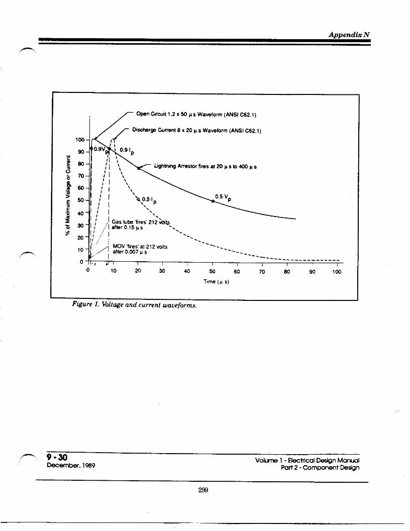
Appendti N
+
,- 9-%Mm*. 19s9
Volum 1- E1-rncal DAgn MawlPati 2- Corn-t hdgn

Traffic Detector Handbook
.—
‘\\-_–___ --~,’. /
‘. -_-.’
80 —
w—
a—
,234567 ?095B~*=,, ‘m
‘igure 2. Voltage in e&h due to dtichargi~ l@htning current at %rvke w
,..—
4. Ohef ~urces of Possibk Damage
9-32 Vobma 1- El@tical -n Manuelkmh, 1939 Wti 2- Corn-t krign
For traff]c sigrral syskms, there are many other sources of transientvoltiges and currents appearing within the controller cabinet, Thesesources are not con sidered as seven as the energy surge th ro@ thesctice neutral and all have proktion detices installad within thecabinet. Some sources are:
(a) Detictor ~ops - dektor sensor units (amplifiers) arepmtac@d internally with their own lightning arreskr and arealso provided with extirnal MOVS at the input file. Failurera@ due to lightning damage is ve~ low as the voltigeimpressed on a loop is caused by mpacitive effects.
(b) Detector Cable - the possibility of induced cuments caused by
(c)
(d)
transient voltages in the earth is minimized by ~ounding thecable shield as close to the Imp as practical (splice point) andleaving the end of the shield cut off and unconnec~d in thecabinet.
Signal Cable - si~al cable is shielded by metal Wles (abveWound) but is subject to induced cuments caused by transientvoltages in the earth. The load switches and the AC-teminalsof the cabinet are protsc@d by MOVS and the failure rats islow.
Direct Hits on Cabinet - altho~h nothing can be done toensure a complete lack of damage, the controller cabinet may
be considered to b protecwd by an umbrella cone of 30” from
an overhead line and somewhat protectad by a 45” cone. It isnot desirable however to install the cabinet directly under thelines due to possible electroma~etic irrtifierence. Thecabinet location should be:
. 13 m minimum from a distribution gmrnd (Figure 4)
● 3 m minimum (horizontdfy) clea of overhead ltnes
● Within the 30° to 45° cone of protecuon (Wthin 15 m fornor-l he~ht lines) of the overhead ftnes ff~ure 4).
301

~affic Detector Handbook
.—
(e) Mreti Wte on Poles or Equipment - his wndition wouldcauae severe damage. me metbd of mitigating possibledamage effects consists of installing a K AWG RW 90been) system grmmd wire mnnating dl poles andintersection equipment and instilling a grmmd ti on eachcorner. Conn=tion of the system ground around tieintersection should be made at one Wint only (the mbinetgrmmd bus) as indimted in Figure 5.
(Improve if rq’d)
F@ue 3. &commended improvemeti to system gmud cmwctbm.

PUN
T
=1
k n
15mm. 4
SECTDN A - A

Waflc Detector Handbook—.
A.ntI
L w,ce9,0.n4
PICTORIAL
SCHEMATIC
Figure 5. Signal Grounding System (mith or wdhout lighting). No grouti electrds atcabinet.
Vol- 1- Elw~cal D@n Manwl9-s —
%@2- ~m-t W*gnDwembr, 1939

Append& N
~mmv of Wsign gu~elim *fion IV
1. Traffic Signal Systems
(1)
(2)
(3)
(4)
DesiW stindard ~ounding systim under normal circumstances:
● Setice ground -4 rods & #2/O bare ground Wre aa perFtgure 3.
● bb~et ground - Sptem ground we connected toabinet ground bus as ~r R@re 3.
. System ground 1 rd or sleel fmung pr tite-clioncorner. #6 insukted tire mnnected to semice groundfrom cabinet ground bus ad [rem ~uipment ground aaper Figure 5.
Use improved design as per Table 3 for grounds in sand, ~avel orrock, Consult Geotechnical information and District Maintenance.
Ground detector cable shield at splice point and cut off in cabinet.(See note)
hcate controller at least 11 m from a hydro pole and at least 3 mhorizontally from overhead lines. bcate controller 1.5 m clearminimum from mehl objects such as poles, fence and ~iderail
Noti.In 1990, his was chmged to : Ground shield in cabinet ud insulate shield at pull box.
9-%k~. 1%9
Volurrra1- EIwtical D-gn ManWlhrt 2- Comwnant hdgn
3a

fiafic Detector Handbook
P.
. -.. -.and Shielding of Elwtronic fiafic Control Equipment”,~anspotiatwn Research Board, NCH RPRepati 317, June, 1988.
( 10) Edco, Inc., “Lightning %otection for Rafic Control”, Edco TechnicalBulletin No. 200-01, May, 1978.
(11 ) Edco Inc. of Florida, Installation Techntial Bulletin # 100484, 1984.
(12) Eptiin, B. M., “For Best Results, fieat Power and ComputirRequirements as One System”, Article in EC&M, pg. 130, Au~st,1986.
(1)
(2)
(3)
(4)
(5)
(6)
(7)
(8)
(9)
Biddle Instruments, “Getting Down b Earth”, A Manual on EanhResistance Testing for Practical Man, 4th cd., 1981
Badle, D., “Electrical Protection Guide for Land-Based RadioFacilities”, Jaalyn Electronic Systems, 1971.
Burns, G. A., “L]ghtning Damage b Tank - Ga@ng EquipmentSolved by Modification Instead of Replacement”, Article in Oil andGas Journal, pg. 93, September 14, 1981.
Canadian Stindards As=tiation, Candian Elmtrkal Cd Pati I,Section 10, Graunding and Bonding, 1987.
Carpenter, R. B., Total Isolation from Lightning Influences”, ZEEE~ansactions an Zndustq Applications, Vol. 1A-17, No. 3, pg. 334,May/June, 1981.
Cuna@n, W. D. & Ayoub, N. A., “Lightning Pro@ction Hardware andTech niques for Electronic fiaff]c Control Equipment”, Fe&ralHighway Administration, Februaq, 1986.
Dasen, ,M., Algonquin College, “Insulation Tester MeWer”.
Dasen, M., Algonquin College, “Meg - Earth Testir”.
Denny. H. W. & fihrbawh. J. P. “fiansient Pro@ction. Grounding.
Vo- 1- EIwWIcal DeSgn Manwl 9-37 ‘—Pan 2- COm~nt btign DKemti, 1989
w
(13)
(14)
(15)
(16)
(17)
(18)
(19)
(m)
(21)
(22)
(23)
Fink, D. G & Beaty, H. W., Stan&rd Handti for ElectrtialE~ineers, Ilth cd., 1978.
Freund, A, “Protecting Computers from ~ansients”, EC&M, pg. 65,April, 1987.
General Electric, ~anstint Voltage Suppresswn, 3rd Edition.
Gunn, R., “Facility Noise Control from the Ground UP”, EC&M, pg.56, April, 1987.
Harder, J. E., Hughes, A E., & Vosicky, J., “hal@ical Method forCo-ordination of Surge Arresters with Cument-Limiting Fuses”,IEEE ~ansactions on Itiust~ &pltiations, Vol. U-17, No. 5, pg.445, September/October, 1981.
Instituts of Electrical and Electronic Engineers, Inc., “IEEE wide forfidio .Methods of Measuring Eafih Conductivity”, IEEE Staadard356-1974.
Institute of Electrical and Electronic Engineers, Inc., “IEEE Guide forSafety in Substation Groundin~, IEEE Sta&ard 80-1976.
Institute of Electrical and Electronic Engineers, Inc., “IEEE Guide forthe Installation of Electrical Equipment to Minimize Electrical NoiseInputs to Controllers from External Sources”, ZEEE Statird518. Z982.
Institute of Electrical and Electronic Engineers, Inc., “IEEE S@ndardPmcadures for the Measurement of Radio Noise from OverheadPower Lines”, IEEE fiansacttins on Power Apparatus and Systems,Vol. Pas -100, No. 8, A~ust, 1981.
Institute of Electrical and Electronic Engineers, Inc., “ModellingCument.Limiting Su~e Arresters”, ZEEE fiamactw~ on PwerApparatus and Systems, Vol. Pas -100, No. 8, A~st, 1981.
be, W. R., The Dangers of Lightning”, Article in ETZ Canoda, Pg27, November, 1978.
307

Traffic Detector Handbook
,-
(24)Michaels, E. C., “Rinciples and Techniques for Grounding andBonding in H~ardous (Classified) hations”, Atiicle in PhntEngineering, pg. 133, September 17, 1981.
(25) Mires, F. M., “Introducing the Varistor”, Atiicle in Computers andElectronics, pg. 88, May, 1983.
(26) Onbrio Hydro Inspection Department, “Electrical Inspection,Provincial Government”, Electrical Impection Guti 26-4, Dewmber,1975.
(27)Ontario Hydro Inspection Department, “Public Roads - ElectricalDevices”, Electrkal Inspection Guide 11-3, A~st, 1984.
(28) Ontirio Hydro Inspection Department, “Rule 10-208, GroundingConnections for ~o or More Building or Stnct&res”, Bulletin ZO.6-0,April, 1987.
(29) Plumber, J. A.& Crouch, K E., Nstional Aeronautics and SpaceAdministration, L&hning Protection for Daffic Control Systems, 1978.
(30) Schwarz, S. J., “halytical Expressions for the Resistance ofGrounding Systems”, Paper presented at the AZEE Summer andPacifti General Meeting, Los hgeles, June, 1954.
(31 ) Stifter, F. J., “Power-Line Disturbances”, Afiicle in Computers andElectronics, pg. 35, Octiber, 1983.
(32) Thomas, P., Ministv of~anspotition, Ontirio, Znoestigatiue ~port- Lightning Problems on 170/332 ~affic Control Systems, June, 1985.
(33) Westerson, A. & Maher, P., “Computer Power - Problems andSolutions”, Article in EC&M, pg. 67, December, 1982.
(M) Westinghouse Electric Corporation, “Electrical ~ansmission andDistribution Reference Book”, 1950.
(35) MinistV of fianspotition of Ontirio, “Equipment, Manmls &Procedures evaluation for the Desi@ & Maintenance of fiafflc Si~alSystems”, Report No. 2, Grounding, May 1988.
—Vol- 1- El+Wcal D~ign Manual 9-39Pati 2- bm~nt k$gn Wembr, 1989

Appendti O
-
@
MnistyofTranspotiation
OnttiO
VOLUME 2-ELECTRICAL MAINTENANCE MANUALPART 2- COMPONENT MAINTENANCE
Chapter 9
Grounding

.
Dafic Detector Handbook
-.
Chapter 9 Table of Contents
-fion I Traffc Sgnal Grounding 3
l. Hvdro Grounds . . . . . . . . . . . . . . . . . . . . . . . . . . . . . . . . ...3
2.SewiceGrounds ..,,.... . . . . . . . . . . . . . . . . . . . . . . . . . . ...33CatinetGrounds. . . . . . . . . . . . . . . . . . . . . . . . . . . . . . . . . . . . ...3
4S@cialtillCondtiiom. . . . . . . . . . . . . . . . . . . . . . . . . . . . . . . . ...45.S@temGround . . . . . . . . . . . . . . . . . . . . . . . . . . . . . . . . . . . ...5
6.Rotilnelmpection . . . . . . . . . . . . . . . . . . . . . . . . . . . . . . . . . . ...57.Emergencylns~ction, .,, ,,, . . . . . . . . . . . . . . . . . . . . . . . ...5
8.Measurements . . . . . . . . . . . . . . . . . . . . . . . . . . . . . ...?9,SteeiFwtings .,,.,,.., .,, ,, .,, ,, .,.,,.,. , ., .,, . . . . . ...710.GroundR~s ...,,..,.. .,, ,,, ., .,, ,,, , . . . . . . . ...10ll.GoadRactice ...,.,., . . . . . . . . . . . . . . . . . . . . . . . ...10 “
*fianll References 11
Volume 2- El~trical Mainte~nce Manwl ,9-1 ‘–Part2--m~nt Maintenaxe *emkr,lW9
310

P9-2 Voh 2- EIwMcal WlnteMwe Manwlkabr, 1%9 Part2- Compo~t Maintewwe
311

fia~c Detector Handbook
1. Hydro Grounds
(1)
(2)
(3)
Inadqwte hydro ~ounds at semice Wle will allow energy fmmlightning discharge inta controller. Inspect Hydro Hounds tisuellyand arrange for Supply Authority @ repair faulty wounds.
At mntroller sites where lightning problems have murred, HydmWound should be reinford ta two 20x3000 mm coppewlad rds at 3m spacing at the setice pole and at one hydro ~le each way, Amangepurchase order for this work if necessa~.
Do not use Hydro @ound as Semite ~und.
2. %rvke Grounds
(1)
(2)
To reduce voltiges transfemed from the Hydro Hound (underIifitning diwha~e) b the Semite mound, the Semite ~und shouldbe Iwated as far from the Hydro ~ound as possible. See Figure 1.
The service ~ound should consist of a minimum of four 20 x 3000mm copperclad ~ound rods on #ZO bare copper wire ~id as perFiWre 1.
3. Catinet Grounds
I (1) PmWr ~und bus bar should be instilled in controller mbinet andall ground leads fmm quipment should mnnect b this one Pinti
(2) Controller cabinet ground bus should bs connected ta the service solidneutral by a #6AWG R~90 insulati system ground wire.
312

Appendk O
(l~rove if req’d)
F@ure 1. komrnetid tiprooement to system ground mnnetwn
4. Sxbl Soil CondWs
(1) Orouding system in areas of sand, gravel or wk may requirereinforcement dw b pr soil mnductivity. Wfer to Electrial hsi~Wnual - Volume 1. Wquest desigrr aid from EIArial Engineering%ction if nwessary.
313

~aflc Detector Handbook
.—
5. System Ground
(1)
(2)
(3)
(4)
System Wound wire for si~als ta be #6 RW90-4@ C ~een.
Inshll mnnections of the three systems (Sewice ~ound, cabinetwound and equipment Wound) as indicated in Fi~re 2.
Ensure that all metil enclosures are knded ta the proper acction ofthe system wound.
All connections ta be thermit weld, impact or compression type (nosplit belts, eti.).
6. Routine lns~tion
—
I (1) Yearly inspection frequency for
(a) tight connections of accessible Wound wires (controllercabinet and sewiceh comosion
(b) hydro and semice flound% visual for obvious damage fromvehicles, eti.
(c) testing of resis~nce @ Hound and wil conductivity (serviceWound) as per sub-section 8.
7. Emergency lns~fmn
(1) For mntrollers damaged by lightning
(a) Insp=tion Hydro ~und as per sub-sastion 1.
314

,m.
P
.—
SCHEMATIC
Figure 2. Signal Groundi~ System (with or without lightind. No groundehctds at cabinet.
315

Trafic Detector Handbook
(b) Have Supply Authority check distribution arrestor andupvade vound and arrestir if required
(c) Inspect for proper instillation of ~ounds as per sub-sectionsl@5.
8. M~surements
(1)
(2)
(3)
(4)
II (5)I
9. Steel Fmtings
Wsistince to mound and soil conductivity should be measured at an‘average’ time of year. Measurements tiken when soil is wet or frozenare not meanin~ul.
Use the Megger wound resistance me~r and the two small wOundrods supplied with the unit. Follow instructions exactly for distincesor results will be meaningless. For information regarding theinstrument, conhct the Electrical Operations Unit.
.—
Measurements b mound to be @ken at the SN of the semice and thecontroller cabinet wound bus.
fisistance to wound and soil resistivity are related mathematically.See Electrical Design Manual - Volume 1 Section 11.
Wsistince to wound should be 10{> or less but can vary up ti 25 (2in high resistivity soils. %adings over 25 () indicate that furtherins~ction and repairs or replacement should be done or thatadditional rods and wire should be added (new instillations). Addadditional elements as per Table 1,
I(1) Steel footings may & considered equivalent of a Wound rti for
resistance to wound purposes.
—Volum 2- Ei=tical ~nte~nce Manwl 9-7 —Pan 2- ~m~t Maintewnce kembr. 1989
316

ksis~ne (Q) ti Ground
GroundAmrding ~ NW of *il
Sysbm clay Sandy ~ayey Sand Sand.
Cotig ascription No-d Use aay Sand Gravel
wation p= p= p= p= p=100 200 500 1500 5000 !Qm h ~m ~ Q“
● 1. Single 20 mm x 3 m Addition ta Sys@m 32 80 160 480 1810
rod
● 2. Single 220x 2300 Poles (requires 28 70 140 420 1400
S*1 Faating additional systim)
● 3. Single 85 x 1830 Poles, Cabinek 40 100 200 600 2000
S*I Faating (requires additional ~syskm)
■ 4.610 x61O x 6 mm Wck overburden 0.6 to 46 115 230 690 2300
Pla* 2.0 m
3 5. Single U6 wire, bare, Addition b systim 41 103 205 2050
3 m long _ — — —
3 & Single #ZO tire, Addition b systsm 38 95 190 1900
ham, 3 m long
3 7. Single #6 tin, 2 *rtice 19 38 95 290 950
rods
S. Single #ZO wire, 2 &tice in overburde n 27 54&
140 410 1400
Plaks
& 9. 220X 2300, S-1 Poles 19 38 95 285 950
Fmting, #6 mm, 1 md
B1
● 10. 85x 1830, S@el Poles 16 34 80 240 800
Faating, #6 tire, lr od
Tabk 1. Resistanm to Groud for Vartius System Comwmnts
—
9-8 volums 2- Elwmcal Mint-me Man~l*em&, 1989 pati 2- Corn-t Maint~~e
317

~afle Detector Handbook
—
ksistince (f2)‘“bGround
Normal Use
Amoral
L~ayey San{Sand
4Clay Sand
— ~a
p= p=100 200Qm h
14 28
Sand~
p=5000&
?00
650
Ascription
i
p= P=500 150CQ. h
11. 85X 1830 SalFmting, $ZO wire, 2
&s
Cabinek 70 I 210
Cabine& T13 26 T65 19512. 85X 1830 SklFmting, #ZO wire, 3
rods
T50 15010 2013. 85x 1830 S@elFmting, #ZO wire, 4
rods
Cabineb 250
—
—.
11 2214. #ZO wire, 4 mds
+
55 165
55 165
550
5. #ZO wife, 4 rods, 2ties
hy for p c 125 11 22 550
T(9) 18 T45 1356. #ZO tire, 4 rods, 2ties, 4@ils
by for 125< p <150 450
T30 90by f~r 150< p <200I
7. #ZO wire, 4 rO&, 2ties, 8 tiils
(6) I 12 300
II
T25 75I
R #20 wire, 8 ro@, 6ties
hy for 200< p <350
L(5) 10 250
—
Table 1, Continwd
—Volm 2- El~wcal Mintmwe Manwl 9-9Pofl 2- ~m~t Maintmme Dmember, 1989
318

10. Ground R~s
(1)
(2)
(3)
(4)
One rod length spacing to be obtained between rods.
Connecting wire is more effective if buried ti U2 the normal frostdepth (assuming snow cover).
Do not insbll rods at more than 4@ angle. Driting jaws for use witha hydraulic drive head are available.
Use 20x 3000 mm copperclad rods only, with thermit weld OTimPactconnecters.
(1)
(2)
(3)
Grounding is a safety device and many members of the Electricalindustry are somewhat lax about proper grounding practices as theonly times they are required are under abnormal conditions such asshort circuits and lightning surges, Poor workmanship or practicesare not apparent until such an abnormal problem occurs.
The Ministry’s grounding system practices should meet or exceed therequirements of the Code. (The Code is a minimum requirement). Ifdoubt exists as to practice, the regulations contained in the Codeshould overrule other opinions.
Workers should endeavour to follow the Ministry’s practices faithfullyso as not b endanger themselves or the Ministry to the possibility Oflegal prosecution due to mishap through poor practice or application.
,-. —
9-1ok-r. 1989
Volum 2- El@Mcal Wlntemme MarruolPati2-m ~t Maintenawe
319

fiafic Detector Handbook
,.—
(1)
ktin II
Minist~ of fiansportation of Ontirio, ‘EquiDment, Manuals &~ocdures Evaluation for Desi~ & Main’tinance of fiafic Si~alSystems”, Repoti No. 2, Grounding, May, 1988.
V-2 - El~wcol Maintemwe Manwl 9-11 -%ti 2- Comp_t MaintWnce ‘ kemkr. 1%9
32o

GLOSS~Y
ACWA~D CO=OLLER A traffic signalcontroller that receives information from ve-hicle an~or pedestrian detectors and protidessi~d timing accordingly.
AC~A~ON The operation ofany type of detector(NEMA). me word operation means an outputfrom the detector system to the controller unit.
AD~SORY DETECTOE The detection of ve-hicles on one or more intersection approachessolely for the pu~ose of modifying the phasesequence antior length for other approaches tothe intersection (NEMA).
ALTERNAT~G C~~ (AC): A currentwhich reverses direction at re~ar intervals.The rate of reversal is expressed inherti (cyclesper second).
-Em The ufit expressing the rate offlow of anelectrical current. One ampere is the currentflowing through one ohm resistance with onevolt pressure.
-UF~R See Detector Amplifier.
ANALOG h electronic design that uses continu-ously varying voltages, rather than digitalnumbers.
ANSk herican National Standards Institute.
ANTENNA The radiating or receiving elementsutfltied in transmitting or receiving electromag-netic waves (NEMA).
-A DE~C~ON The continuous detection ofvehicles over a length of roadway wherein thecall of a vehicle in the detection area is intendedto be held for as long as the vehicle remains inthe area of detection. (Most detectors cannothold the cdl indefinitely.) Frequently refereedto aslarge-area detectors, long-loop detectors, orpresence detectors.
-A OF DE~C~ON See Zone of Detection.
AREA DETECTOR See Large &ea Detector.
&TE~ A major urban roadway usually withcoordinakd si~als along its length.
ASW me kerican Society for Testing and Ma-terials.
A~YEQW~ Separate deticesusedto add supplementi~ features b a controllerassembly (NEMA).
AWG herican Wire Gauge. The standard meas-urement of wire she. It is based on the circdarmil systim. 1 Mfl eqwls .001.
C=LE: A ~oup of separately insulated conduc-tors wrapped together and covered witi an outerjacket.
C- A registration of a demand for right-of-wayby tr=lc at a controller ufit (NEMA). The callcomes to the controller from a detechr that isoutputting an actuation.
CALL~G DE~CTOR A detector that is in-stalled in a selected location b detect vehicleswhich may not otherwise be detected, and whoseoutput may be modfied by the controller unit(NEW). This traditionally has meant a smallarea detector near the Stop Line, to detect ve-hicles entering the roadway from a drivewayduring the red or yellow si~al. me detector isdisconnected when the ~een si~al is displayedso that extensions of the ~een can only comefrom the appropriate Extinsion Detector.
C=ACITANCE. That property of a system ofconductors and dielectrics which permits thestorage of electricity separatid charges whenpotsntial differences exist between the conduc-tors. Its value is expressed as the ratio of anelectric charge to a potential difference.
321

~aflc Detector Handbook
,—.
CARD-RACK MO~TED DETECTO= SeeRack Mounted Detectors.
CARRYOVER OUTPUT: The ability of a detectorto continue its output for a predetirrninedlen@hof time following an actuation (NEMA). SeeExtended Call Detector.
C~= Diagonal saw slots at the corners ofsquare or rectan~ar loops to reduce the angleof bend of the loop wires at the intersecting sawslots.
CWGE IN~RV~ Tbeyellow internal follow.ing the green signal indicating the change to aconflicting phase.
CW~L Electronic circuitry which functions asa loop detector unit (NEMA).
C~C~~ A closed path followed by an electriccurrent.
CLEARANCE mRV~ A red intimd thatmay be shown following the yellow change inter-val before allowing a conflicting green signal tobe displayed.
CO~ A coiled conductor, wound on a form or corewhich uses electro magnetic induction to causechanges in a cument.
CONDUCTANCE The measure of abflity to coti-duct electricity.
CO~UCTOR A medium fortransmitting electri.cal current. A conductor usually consists ofcopper or other materials.
COND~T A tube for protecting electrical wires orcables.
CONFLIC~G Cm See Seficeable Conflicbing Cdl.
CONFLIC~G PHASES Two or more tr~lcphases which till cause interfering (i.e., con-flicting) traffic movements if operated concur.rently.
CON~NUOUS P~SENCE MODE Detectoroutput continues if any vehicle (first or last
remaining) remains in the field of influence(NEMA). This definition does not imply that theuse of this mode guarantees that the output wHIcontinue indefinitely, as most detectors are in-capable ofholding a cdl beyond a finite intend.See Detector Mode.
CONTROLLED OUTP~ The abdity of a detec-tor to produce a pdse that has a predeterminedduration regardless of the length of time a ve-hicle is in the field of ifluence (NEMA). SeeDetector Mode.
CON~OLLERASSE~LY: A complete electri-cal mechanism mounted in a cabinet for control-ling the operation of a traffic control signal(NEMA).
A
B.
c.
D.
~ffic-Actuated ControUerAssembI~A controller assembly for supemising theoperation of traffic control signals in accor.dance tith the varying demands oftrafflc asregistered with the controller by detectirs(NEMA). —.
Semi-fiaffic-Actuated Controller As:semb~: A type oftrafic actuated controllerassembly in which means are provided fortraffic actuation on one or more but not all
approaches to the intersection (NEMA),
Full-Traff~c-Actuated Controller As-sem-bly. A type of trafic actuated control-ler assembly in which means are providedfor traffic actuation on all approaches to theintersection (NEW).
Pedestrian-Actwted ContmMerAssom-. . . . . .
blw A controller assemoly in Which inter-vals, such as pedestrian WWK and clear-ance intervals, can be added to or included inthe controller cycle by the actuation of apedestrian detector (NEMA). Pedestrianactuation may be part of an intersectioncontroller or be used to control a midblockcrosswalk.
CONTROLLER ~ A controller unit is thatpotion ofa controller assembly that is devoted tothe selection and timing of signal displays —(NEW). Mso referred to as the Dispatcher orTimer.
322
,!

Detector Handbook G1OSSW
n
CNmCa _RSEC~ON CONTROL (CIC):k algorithm employed in traffic systems to dy-namically control the split at signalked loca-tions where the traffic patterns are such thatspecial control, responsive to changing condit-ions, is needed.
CW~CAL LANZ DETECTION. A system ofhardware and software designed to pr,otide dataon trfic flow for a selected lane, usually theheaviest volume lane on an approach to a signd-tied intersection.
CROSST- The adverse interaction “of anychannel of adetector unit with any other detec-tir channel (NEMA). It is the m,utwl coupfingof ma~etic fields that produces intertiotionbetween two or more detector units in the samecabinet when the units are operatiug at simfiarfrequencies. Crosstalk restits in a detectoroutputting an actuation in the absence of avehicle.
~, CYCLE: A complete sequence of all si~~ indica-tions at an intersection. In an actuated control-ler, a complete cycle .is dependent on the pres-ence of detectir calls on all phases.
CYCLE LENG~. The time period in secondsrequired for a complete cycle. Cycle length isnormally variable for actuated intersectionsunless they are pati of a coordinated system.
DELA~D CALL DETECTOR A detector thatdoes not issue an output until the detection zonehas been occupied for a period of time thatexceeds the time preset on an adjustable timerinco~orated into the detectir unit.
DELAYED O~P~ The abflity of a detector todelay its output for a predetermined length oftime during.an extended actuation (NEMA).
DELTA L (L): The change in inductance.
DE~ The request for semice, e.g., one or mOrevehicles desifing to use a given segment ofroad-way during a specified unit of time.
_ DE~ CONTROG. See Loop Occupancy Con-trol.
DE~ OPE~TION A mode of operationwhereby the sefice provided at an intersectionreflects the presence of demand for that serticewithout regard to back~ound cycles.
DENSIH A measure of the concentration of ve-hicles, stakd as the number ofvehlcles per mileper lane.
DENSITY CONTROLLER Actuated controllerthat h.as.timing adjustments for the selection ofthe allowable gap independent of the passagetime. A volume-density controller and a modi-fied density controller are each a type Of.densitycontroller..
DESIGN SPEED the speed used as typical by thedesi~er of the detector/controller system in thekinematic analysis of the scheme under freetraffic flow conditions.
DETECYTON ZOW mat area of the roadwaywithin which a vehicle will be deticted by avehicle detector (NEMA). Mso called “zone ofdetection” or “sensing zone.”
DETECTOR A device for indicating the presenceor passage of vehicles or pedestrians (NEW).~is general term is usually supplemented witha modifier indicating type (e:g., 100P detectOr,ma~etic detector, etc.); operation (e.g., pointdetector, presence detector, etc.); or function(e.g., calling detector, extension detector, etc.).
DETECTOR AM=~~R A device that is ca-pable of intensifying the electrical ener~ pro-duced by a sensor (NEMA). h example is ama~etic detector amplifier. A loop detectorunit is commonly called an amplifier, althoughits electronic function actually is different.
DETECTORF~WS The occurrence ofdetec-tor malfunctions includlng non-operation, chat-tering, or other intermittently erroneous detec-tions.
DE~CTOR ~MORY The retention of an ac-tuation for future utiltiation by the controllerassembly. The phrase might better be detectionmemo~ to make it clearer that the memory iswithin the controller, not the detectir.
323

Traffic Detector Handbook
,—
DETECTOR MODE: A term used to describe theoperation of a detector channel output when apresence detection occurs (NEMA). See PulseMode, Controlled Output, Continuous PresenceMode, and Limited Presence Mode,
DETECTOR SETRACK Longitudind distancebetween stop line and detector.
DETECTOR SYSTEW The complete sensing andindicating floup consisting of the detectar unitin the controller, the lead-in cable, the lead-inwires, and the sensor.
DETECTOR HT: The portion of a detectorsystem other than the sensor and lead-in cable,consisting of an electronic assembly.
D~LECT~C ~y insulating material that is anonconductor of electricity.
D~MMA ZONE: A disbnce or time intervalrelated to the onset of the yellow intemd. Origi-nally the tem was used to describe that portionof the roadway in advance of the intersectionwithin which a driver can neither stop prior tothe stop line nor clear the intersection beforeconflicting trafic is released. That usage per-tained to insufficient len@h of timing of theyellow antior all-red internals, More recentlythe tem has been used to describe that portionof the roadway in advance Of the intersectionwithin which a driver is indecisive regardingstopping prior to the stop line or proceeding intoor through the intersection. May alsO be ex.pressed as the increment of time correspondingto the dilemma zone distance,
D~MMA-ZO~ PROTEC~ON Any methodor procedure that attempts to cOntrol the end ofthe ~een interval so that no vehicle will becaught in the dilemma zone when the signalturns yellow.
DI~CT C~ENT (DC): an electrical cumentwhich travels unifomly in one direction.
DRIFT Change in the electrical propetiies of thedetector system or a portion of it due to environ-mental changes particularly temperature vari-ations and rain water.
EDDY C~W An electric current inducedwithin the body of a conductor when that con-ductor moves through a nonuniform maWeticfield.
EF~CT~ LOOPAR~ See Zone ofDetection.
ENCAPS~TIOM The process of filling the sawslot with sealant to sumound the wires in theslot and protect them from traffic, weather, etc.
ENCASE~: The loop wire is encased in apol~nyl or polyethylene tube h provide protec-tion for the wire. Ofien refereed ta as Detict-a-duct or other similar commercial names.
EPO~ A resin used in bonding.
EXTENDED CALL DE~CTOR men selected,this detector extends the output (See CarryoverOutput) after the vehicle departs the zone ofdetiction for a preset time.
EXTENDED CALL ~~G A detector tith _car~over output. It holds or stretches the call ofa vehicle for a period of seconds that has been seton an adjustable timer inco~orated into thedetector. It can be desi~ed ta begin the timingof that period when the vehicle enters the detec-tion area, or when it leaves. The latter is speci-fied by NEMA. Mso referred to as a “StretchDetector.”
~SION DETECTOR A detector that isarranged to register actuations at the controlleronly during the green intewal for a given ap-proach so as to extend the Ween time for that
apprOach ta accommodate the actuating vehicles,It is not active during the red or yellow internalsfor that approach.
EXTENSION LI~~ The maximum length oftime that the actuations on any traffic phasemay rehin the righbof-way after an actuationon an opposing traffic phase. Also known asmafimum Ween.
F~SAFE (as in output relay desi~): A typeofoutput-relay design that produces a constant _call, thereby keeping trafic moving, in the eventthat the detector unit fails.
324

Detector Handbook Glossao
F~. Autit of capacitance, usually expressed inmimofarads (pF), one millionth of a farad.
~EDER CARLE See Lead-In Cable.
FELD OF ~UENCE See Zone of Detection.
FREEWAY SUR~~CE Process or methodof monitoring freeway traffic petiormance andcontrol system operation.
FREQUENCY The number of times an alternat-ing cument repeats its cycle in 1 second.
FULL-~FIC-AC~ATRD CONTROLLERASSEMBLY A type oftrfilc-actuated control-ler assembly in which means are provided fortrfilc actuation on all approaches h the inter-section.
G- The time internal between the end of onevehicle detetior actution and the beginning ofthe next actuation.
GAP OW Terminating of a ~een phase due to anexcessive time intemd between the actuationsofvehicles amitingon the~een, so ~een maybeserved to a competing phase.
GAP ~DUC~ON ~ feature whereby the unitextension or allowed time spacing between suc-cessive vehicle actuations on the phase display-ing the Ween in the extensible potiion of theinterval is reduced (NEMA).
GREEN ~TENSION SYS~M Hardware as-sembl~ of extended cdl detectors and auxiliarylogic. Ehe logic can motitor the si~al display,enable or disable the selected extended calldetectirs, and hold the controller in artery ~een.
GRO~. The earth and all parts conduc-tivelyconnected to the earth.
HAND HO~ See Pull Box.
HENRY (h): The measure of inductance, defined asthe inductance of a circuit in which a counterelectromotive force ofone volt is generated whenthe current is changing at the rate of one ampereper second.
HER~ @z): A term replacing cycles-per-secondas an indication of frequency.
HOD A command that retains the existing right-of-way. A command to the controller whichcauses it to retain the existing right-of-way. Amomentary release of the hold command allowsthe controller to yield to other conflicting phasesrequesting sewice (ofien refereed to as the yieldcommand or yield point).
HOLD ON LN: A connection that modifies acontroller from full-actuated, isolatid operationto semi-actuated, system controlled operation.It is used as the basic tie from the local intersec-tion b the system master.
HOW-RUN C=~ See Lead-In Cable.
HONDA 100 A small motorcycle commonly consid-ered to be the smallest registered motir vehicle.It is used as the baseline for motorized vehicledetection.
W (HERTZk A measure of frequency in cycles persecond.
ph (~CRO HENRM: A measure of inductance.See Inductance.
IMSA The International Municipal Si@al Asso-ciation.
~UCTANCE: That propetiy ofanelectric circuitoroftwo neighboring circuits whereby an electro-motive force is generated in one cirmit by achange of cument in itself or in the other. Theratio of the electromotive force ta the rate ofchange of the current. Measured in micro hen-ries (@).
~UCm~CTANCE: The reactance (ohms)of an ideal (Iossless) inductor is the product ofthe voltage across the inductor and the sine ofthe phase angle (90 de~ees) between inductorvoltage and current divided by the inductorcurrent assuming sinusoidal operation.
~D DETECTOR A detector that sensesradiation in the infrared spectrum (NEMA). Adetector installed over the roadway capable ofbeingactuatedby the passage ofavebicle throughits field of emitted eledromagnetic waves.
325
fiaflc Detector Handbok
~N POR~ON The first timed potiion actu-ated controller Unit
A
B.
Fixed Initial Portiom A preset initialportion that does not change.
Computed Initial Potiiom An initialportion which is tr~lc adjusted.
C. Maximum Initial Portion: The limit of thecomputed initial portion.
D. Minimum kitial Portiom (see “Fixedinitial POtilOn”).
E. Added Initial Portion: An increment oftime added to the mitimum initial portionin response to vehicle actuations.
WTERVAL: The pati of parts of the si~al cycledufing which signal indications do not change(NEW).
ISOLATED mRSEC~ON CONTROb Fomof signal control for a single signalized intersec-tion thro~h which the flow of traffic is con-trolled without consideration of the operation ofadjacent si~alized intersections.
ITE: The Institute of fiansportation Engineers.
~C~ON BOX See Pull Box.
~O~RTZ (W): Thousands ofherti. Ameas-ure of frequency.
L The symbol used for inductance.
U The change in inductance.
LARGE -A DETECTOR A detector or seriesof detectors wired together in series, parallel, orsefies/parallel covering an area in the approachto an intersection. Detection area varies from 6x40 ft(l.8x 12m)to6x100fi (1.8x 30m)orlarger. One of the more common confi~rationsis four 6- x 6-ft (1.8- x 1.6-m) loops spaced 10 ft (3m) apart for a length of 54 ft (16.5 m).
LAST Cm PASSAGE A selected feature of adensity contro~er which, upongap-out, will causethe ~een to complete the timing of the passagetime. The last vehicle to have been detected,known as the Last Car, will therefore retain theqeen until it reaches the stop line. Thus, it isassured of avoiding the dflemma zone problemand of clearing the intersection. This feature isnot defined by NEMA, however, a number ofmanufacturers provide it.
LRAD-~CABLE: The electrical cable which seinesh connect the lead-in wire in the pdl box to theinput of the loop detector utit in the controllercabinet (NEMA). Sometimes called %ome-run,,cable “ortransmission line.
LEAD-~ =: That portion of the loop wire thatis between the physical edge of the loop and thepull box which should be twisted a specifiednumber of turns per foot. For a magnetic detec-tor or a maWetometer, it is the wire which mnsfrom the sensor (probe) to the pdl box.
.—
LIGRT-SENSIT~ VE~CLZ DE~CTOR Adetictor consisting of a light source and photoe-lectric cell or cells, capable of being operated bythe passage ofavehicle intemptingthe beam orbeams of light. men properly equipped, direc-tional characteristics are present.
LI~~D PRESENCE MODE: Detector outputcontinues for a limited period of time ifvehiclesremain in the field of influence. See DetectorMode.
H: The length of roadway between two si~al.ized locations.
LIR See Local Intersection Proflam.
LOC& CONTROLLER A controller supervisingthe operating of tr~lc si~als at a single inter-section. Aso see Controller Assembly andController Unit.
LOCAL m~EC~ON PROGU (LW): AType 170 software proflam developed by Cal-trans which inco~orated detector timing fea, —tures within the pro~am.
326
.

Detector Handbook GlossaW>
n
LOC_GDETEC~ONMRMORY: Aselectiblefeature of tie cirmit design for a controllerphase whereby the cdl of a vehicle arnting onthe red (or yellow) is remembered Orheld by thecontroller afier the vehicle leaves the detectionarea untfi it has been satisfied by tie display ofa Ween internal to that phase.
LOOP DETECTOE A detector that senses achange in indu~ance ofits inductive loop sensorcaused by tie passage or presence of a vehiclenear the sensor (NEW). See Nso Loop Detec-tor System.
A Motion Loop Detector, Nondire~lomkA induction loop detector which is capableof being actuated by the passage ofa vehicleover any portion of the loop.
B. Motion LOOD Detector, Directiomk Aninduction lo~p detector” consisting of twoseparate loops either closely spaced or par-tially overlapping which is not affected bythe passage ofavehicle except in the desireddirection.
Presence LOOD Detecto~ h inductionloop detector w~ch is capable of detectingthe presence of a standing or moving vehiclein any portion of the effective loop area.
LOOP DETECTOR SYSTEM A vehicle detectorsystem that senses a decrease in inductance ofits sensor loop(s) during the passage or presenceof a vehicle in the zone of detection of the sensorIOOP(S) (NE~. Means the same as loop detec-
tor but is clearer in its inclusion of the tire aswell as the electronics package.
LOOP DETECTOR ~~ h electronic devicewhich is capable ofene~ingthe sensor loop(s),of monitoring the sensor loop(s) inductance,,and of responding to a predetermined decreasein inductance with an output which indicatesthe passage or presence ofvehicles in the zone ofdetection (NEMA). It is the electronics package,exclusive of tie loop(s) and lead-in cable.
LOOP OC~ANCY CONTROU A detector/controller desi~ using long detection loop(s)(nomdly 30ft (9 m) or longer), and a controller
utit operated in the non-locking mode. A loopoccupancy controller may, but need not neces-sarily, be desiWed to rest in d red in theabsence of any trafic dem~d. Loop ocmpacycontrol can utflize magnetometer detectors aswell as loop detectors.
LOOP SYSTEM A combination of loop of wireconnected through lead-in cable to the detectorin-put timinals.
LOOP LEAD-~ m: me portion of the loopwire that is not a part of the loop but is in thesawslot connecting the loop to the edge of theroadway, where it is camied in condtit to thecontroller or else to a prdl box, where it isconnected to the lead-in cable.
LSI C~P: h electrical component tithmore than1,000 logic elements. This is “large scrde inte-gration” of miniature elements and is used insome loop detector ufits of di@ti design.
~GNE~C DETECTOR A detector that senseschanges in the Earth’s magnetic field caused bythe movement of a vehicle near its sensor(NEMA). A vehicle detector placed under theroadway which makes use of both the Eatih’sma~etic field and the energy change created bythe passage of a vehicle over the detector toproduce an output. Not to be confused with amagnetometer detector.
A Compensated fiaetic Vehicle Detec-
B.
to~ &y ma~etic detector which is sodesigned and structured as not h be affectedby changing electromagnetic ifiuence otherthan those resulting from the passage of avehicle. men properly equipped, a com-pensated magnetic detector has substantialdirection characteristics.
NonWmDensated ~metic Detecto~kyma~>tic detector o&erthan a compen-sated ma~etic detector.
~GNE~C S~OW The distortion of the fluxlines of the EartKs magnetic field as they passthrough aferrousvehicle, due to the fact that thevehicle is more pemeable to these flux linesthan is air.
327
,,

fia~c Detector Handbook—
MAGNETOMETERDETECTOE Adetectorthatmeasures the difference in the level of the EatiWsmagnetic forces caused by the passage or pres-ence of a vehicle near its sensor (NEMA). Adevice capable of being activated by the mag-netic disturbance caused by the passage or pres-ence of a vehicle. A magnetic flu generator/sensor is installed in the roadway and connectedto sensor amplifier electronics. Not to be con-fused with a ma~etic detector.
MMUM GREENLI~~ The maximum fleentime after an opposing actuation, which maystart in the initial portion.
MEGGER A detice used by power companies tomeasure very high resistance to earth ~ound.
~GOHM One mfllion ohms, which is the utit ofelectrical resistance.
~MORY OFF. A selectable feature of an actuatedcontroller, synonymous tith non-locking detec-tion memory.
~CROHENRY One millionth of a hen~, fromthe unit of measurement of inductance. Symbol-ized ph.
~ G~EN mRV~ The shotiest~een time of a phase. If a time setting controlis designated as amitimum Ween,” the ~eentime shall not be less than that setting.
~~ VEHICLE STANDARD: A test unitthat produces the minimum change in input forwhich the detector system must sense and indi-cate passage or presence. NEMA specifies aClass 1 vehicle (a small motorcycle).
MO~ONDETECTOR Adetictor that detects themotion of a vehicle passing through the zone ofdetection of the detector at some mitimum speedusually 2 to 3 mph (3.2 to 4.8 kph). Vehiclestraveling slower than the mitimum speed orstopped in the zone of detection are not detected.
NANOHENRY One bfllionth of a henry, from theunit of measurement of inductance.
NEW The National Electrical Manufacturers Aa-sociation.
NENO~ A series of intersecting atierials orstreets that are a part of a coordinated signalsystem.
A Open Network: A network where the
arterials do not intersect more than once(i.e., there are no closed loops in the systim).
B. Closed Network A network that containsclosed loops.
NO~AL NUCTANCE A design value ofinductance where the actual value can vary fromthe nomial tithin a raWe that pemits satisfac-tory eqtipment operation.
NON-CONFLIC~G PHASES ~o or moretrtilc phases which till not cause intiflacingtraffic movements if they are operated concur-rently.
NON-D~CTIONAL DE~CTO~ A detectorcapable ofbeing actuated by vehicles proceedingin any direction. ,—
NON-LOC~G ~MORY A mode of actuated-controller unit operation which does not reqtirememory (NEMA). In this mode of operation thecall of a vehicle amiving on the red (or yellow) isforgotten or dropped by the controller as soon asthe vehicle leaves the detection area.
OC~ANCY: The proportion of time a detectir isoccupied. Ocmpancy is a pseudo measure ofdensity on a roadway.
O= The unit of electrical resistance equal to theresistance through which a current of one am-pere will flow when there is a potential differ-ence of 1 volt across it.
PASSAGE DETEC~ON The ability of a vehicledetector to detect the passage of a vehicle mov-ing through the detection zone and to i~ore tbepresence of a vehicle stopped within the detec-tion zone (NEMA).
PASSAGE DETECTOR The ability of a vehicledetector to detect the passage of a vehicle mov- _ing through the detection zone and to i~ore thepresence of a vehicle stopped within the detec-tion zone (NEMA).
328

Detector Handbook G1OSSW
P
PASSAGE PE~OD The time allowed for a ve-Klcle to travel at a selected speed from thedetector b the nearest point ofconflictingtrafflc(NEMA).
PASSAGE TM: The timing internal during theextensible portion which is resetable by eachdetectir actuation. The green right-of-way ofthe phase may teminati on expiration of theutit extension time. Nso known as VehicleInternal or Preset Lap.
PEDES~AC~ATED CONTRO~RSSE~LM Acontrollerassemblyin which inter-vds, such as pedestrian WALK and clearanceintervals, can be added to or included in thecontroller cycle by the actuation ofa pedestriandetector.
PEDES~ CLEARAN CE mRV& Thefirst clearance internal following the pedestrianWALK indication, nomally flashing DON’TWALK A detector that is responsive h opera-
,-. tion by or the presence ofa pedestrian (NEMA).
PEDES~ DETECTOR A detector that isresponsive h operation by or the presence of apedestrian (NEMA). This traditiondlyhas beenof the push-button type, installed near the road-way and operated by hand. Preferably it shouldhave some form of pilot light to indicate uponactuation that the unit is operating, but this israrely provided because of susceptibility tovanddism. Mso, NEMA does not provide anoutput to Hluminate this indicator.
PEDES~ P~E: A trtilc phase allocatedto pedestrian traffic which may provide a right-of-way indication either concurrently with oneor more vehicular phases, or to the exclusion ofdl vehicular phases.
PEDESTR~-ACTUATED CONTROLLERSee Controller Assembly.
P-E A traffic signal phase ,has two differentmeatings in trtilc signal timinology, as fOl-Iows:
,P
A NEW A vehicular phase is a phase whichis allocated to one specific vehicular trafic
B.
movement (e.g., east bound through trtilcas timed by a dual ring controller unit). SeeConflicting Phases and Non-ConflictingPhases.
TBAD~ION= A Dart of the cycle allo-ca~d to any specflc trafic movement re-ceiting the right-of-way orb any combina-tion oftrafflc movements receiving the right-of-way simdtaneously during one or moreinternals.
P~E SEQUENCE: A predetermined order inwhich the phases of a cycle occur.
PO~ DETEC~ON: The detection of vehicles asthey pass a specflc point on the roadway. Fre-quently referred to as small area detection.
PO~ DE~CTOR A detector that measuresthe passage of vehicles pasta point (i.e., a smallarea usually not exceeding 6x 6 ft (1.8x 1.8 m)).Nso refereed to as a Small &ea Detector.
POLYC~OROP~~: Chemical name forNeoprene. Used for jacketing wire and cablethat til be subject to rough usage, moisture, ofi,~eases, solvents, andorchemicds. May also beused as a low voltage insdating material.
POLYE~~ A family ofins~ating materi-als derived from the polymerkation of ethylenegas. Ml members of the family are excellentdielectrics. Electrically they are far supefior toany other extruded dielectric in use today. It hashigh insulation resistance, high dielectricstrength, and good abrasion resistance Polyeth-ylene is being widely used for insulation onsi~al and detector wire and cable. They aresuitable for direct burial.
POLYOLEF~S A famfly of plastics includingcross-linked polyethylene and various ethylenecopolymers which shrinks when heat is applied.Commonly used in splicing.
POLYPROPYLENE: A thermoplastic with goodelectrical characteristics, high tensile strength,and resistance to heat.
POLYS~FONE: A polymer highly resistant tomineral acid, alkali, and salt solutions.
329

Traflc Detector Handbook
POL~~: Enamel that has excellentmoisture resistance, easily soldered, and excel-lent winding propetiies.
POL~ C~OR~E (PVC): A family ofinsulating compounds whose basic in~edient iseither polytinyl chloride or its copolymer withvinyl acetite. Can be either rigid as used inconduit for prefomed detector loops or flexibleas used in duct tubing to encase detector wire. Itis also widely used as insulation material onwire known as types T and ~ used in detectorapplications. frown as PVC or Vinyl.
PO~RHE~ A small 3-x 6-ft (0.9- x 1.9-m) loopinstalled at the stop line end of a long loop inorder b improve the detection of small vehicles.It usually has multiple turns of wire and mayhave an angled confiWration,
P~SENCE DETEC~ON The ability of a ve-hicle detector to sense that a vehicle, whethermoving or stopped, has appeared in its field(NEW).
PRESENCE DETECTOR The abfiity of a vehicledetector to sense that a vehicle, whether movingor stopped, has appeared in its field (NEMA).The sensor may cover a large area or be a seriesof small sensors tired together in series, paral-lel, or series/parallel.
PRESENCE DETECTOR fiafflc detector whichis able to detect the presence or absence of avehicle within its field of detection.
PRESENCE HOD~G T~: The time that adetector system wfll continue to indicate thepresence ofavehicle over one ofits loops withoutadjusting to consider the vehicle a new environ-ment. Upon making this adjustment the actua-tion is terminated. NEMArequires that a Class2 vehicle (large motir cycle) he detected for amitimum of 3 minutes.
PRESENCE LOOP DETECTOR An inductanceloop detector which is capable of detecting thepresence of a standing or meting vehicle in anyportion of the effective loop area (ITE).
PRESET GAP: See Passage Time.
P~SSURE DETECTOR A detector used forwell over 40 years that consisted of two metalplates separated hy spacers. men a vehicle tirepassed over the detictor, it compressed thespacers and allowed the two plates to makecontact, thereby closing an electrical circuit.This type of detictor normally produced two ormore pulses per vehicle because each axle wouldcause a contact.
PROBE: The sensor fom that is commody usedwith a ma~etometer-type detectir (NEMA). AmaWetic detection sensor is also referred to asa probe.
PROGRESS~ ~OW Coordinated movementalong an arterial at a given speed is termedproflessive flow.
P~BOX Acontainerusudly at least 1 cubic footin size that is placed under~ound with a remov-able cover flush tith the gound sutiace. Splicesbetween the loop lead-in wires (or magnetome-ter or ma~etic detector cables) and the lead-in .—cable to the controller cabinet are located in thepull box..
P~SE MODE: The detictor produces a shortoutput pulse (between 100 and 150 ms) when avehicle enters the sensor loop zone of detection,This occurs even though the vehicle rem tins inthe detection zone for a longer time. See Detec-br Mode.
Q See Quality Factir.
QUADRUPO~ A loop configuration that adds alongitudinal sawslot along the center of therectangle, so that the wire can be installed in afi~re-eight pattern, thereby producing fourelectroma~etic poles instead of the normal two.The design improves the sensitivity to smallvehicles and Aso minimizes splashover. Nsospelled Quadrapole and Quadripole in variousdocuments.
QU&I~ FACTOR A numerical index for ratingthe quality of a resonant circuit. A highernumber indicates less losses and increased de-tection sensitivity in a resonant type detector —system.
330

Detector Handbook Glossam
Q~~ DETECTOR Component of a tr=lccontrol systim which senses the presence (ornumber) of vehicles waiting in a queue at anintersection or on a freeway ramp.
Q~~ LENG~ Number of vehicles that arestopped or slowly moving in a line where themovement of each vehicle is constrained by thatof the lead vehicle.
RACK MOUNTED DETECTORS Detictor unitsthat have no enclosing case and, therefore, mustbe placed in the controller cabinet by insetiingits printed circuit board inti a wired receptacleor “rac~ made for the pu~ose. Compare ShelfMounted Detectors.
RADAR DE~CTOR A vehicle detector instilledabove or adjacent (side mounted) to the roadwaycapable of being activated by the passage of avehicle through its field of emitted microwaveenergy.
RADIO-= Q~NCY DETECTOR A vehicledetectir consistingofa loop of wire embedded inthe roadway that is tuned to receive a prese-lected radio frequency from a transmitter lo-cated on a vehicle.
~ACTANCE The reactince (ohms) of a circuitcomponent is the product of the voltage acrossthe component and the sine of the phase anglebetween the voltage and the current ditided bythe cument through the component assumingsinusoidal operation.
RED CLEARAN CE -RV- A clearanceinternal which may follow the yellow intimdduring which both the terminating phase andthe next right-of-way phase displayed (NEMN.
~~C~ON (A~acent Lae): The ability of adetector not b output an unwanted actuationcaused by a vehicle in a land adjacent to that inwhich the detector is located.
~LUCTANCE The opposition which a magneticmaterial or magnetic circuit offers h the pas-sage ofma~etic lines offorce. Reluctance is thereciprocal of permeability (the abfiity ofa metalto conduct fines of force) and pemeance (the
331
measure of that conductivity). Therefore, reluc-tance is relatad to permeability and pemeancein much the same way as resistance is related toconductance in electic circuits.
~PHASE. The process of resetting, after a pdseactuation, to enable another pulse actuationshould another vehicle enter the detection area.Can dso be used as a verb: “The detector shallrephase 2 seconds after inittiting an outputpdse:’.
RES~ h organic substince tbt is a non-conduc-tir of electricity. Resins are widely used forinsulation and encapsulation.
RESISTANCE me opposition that a detice ormatertil offers to the flow of direct current,equal to the voltige drop across the elementditided by the current tirough the element.
RESONANT ~QUENCY The natural vibra-tion frequency of a loop and its lead-in wire, towhich the detector uit must tune.
~SPONSE ~~: The time a detector takes torespond h the initiation of a detection by avehicle.
~ST-~-RED: A controller operational modeintended to display red to dl movements, in theabsence of any traffic demand.
SAMPL~G DETECTOR Any type of vehicledetector used h obtain representative tr~lcflow information (NEMA).
SC~GDE~CTOR Amulti-channel detec-tar in which the loop(s) of each channel areene~zed in sequence, one at a time, in qticksuccession.
SE~~ The material used in a saw slot ofaloopdetector to seal the wires in the slot.
SELF-POWERED VEHICLE DETECTOR(SPVD): Adetectorburiedin the pavement thatuses a self contained battery for power andtransmits the detector information to the con-troller without the need for direct connection(lead-in cable).

~a~c Detector Ha&book—
SELF-~C~G DETECTOR A loop detectorufit, not necessafiy self-tuning, that includeselectronics that compensate for environmentaldrift.
SELF-~G LOOP DE~CTOR ~T Onethat is capable of adapting its operation to theresonant frequency of the loop and lead-in tirewithout any manual adjustment required. meterm applies particularly to the start-up of thedetector’s operation, upon turn-on. CompareSelftracking Detector.
SEMI-TRAFFIC-AC~ATED CONTROLLERASSEMBLW A type oftrafflc-actuated control-ler assembly in which means are provided fortraffic actuation on one or more but not all
approaches to the intersection.
SENS~G ZO~: See Zone of Detection.
SENSI~~ AC it relates to a loop systim thechange in total inductance of a system caused bya minimum vehicle at one loop, expressed as apercentage of the total inductance, As it relatesto a detector, is the minimum inductance changein percent reqtired at the input teminals hcause the detector to actuate.
SENSOR (SYSTEM AND LOCAL): Mafflc detec-tion devices (detectors) that pemit the systemmaster or a local controller to obtain informationas to the trafic flow characteristics in the areaof the sensor. (see Detector. ) NEM limits themeaning of ’’sensor” to the sensing element ofadetector.
SENSORLOOP An electrical conductiramangedto encompass a portion of the roadwayti providea zone of detection and designed in such a waythat the passage or presence of a vehicle in thezone causes a decrease in the inductance of theloop that can be sensed for detection pu~oses(NEW).
SE~S-P~ h Type Ofelectrical intercon-nection of four 6- x 6-ft (1.8- x 1.8-m) loops,usually 9 ft (2. 7 m) apart and installed in a linein one lane to give a 51 ft (15,3 m) length ofdetection area. This interconnection schemegives a combined inductance close to optimum.
SERWCEAB~ CONFLIC~G CALL A callwhich
A
B.
c.
Occurs on a conflicting phase not having theright-of-way at the time the call is placed.
Occurs on a conflicting phase which is ca-pable of responding to the call.
men occurring on a conflicting phase oper-ating in an occupancy mode, remains pres-ent untfi given its right-of-way (NEW).
S-m The outer covering or jacket over theinsula~d conductors to provide mechanicalprotection for the conductors.
S~LF MOUNTED DETECTO~ Units thathave an enclosing case and, therefore, can belocated in the cab,net by placing them on a shelf.They can shnd alone. Compare Rack MountedDetectors.
SH~D. A conductive material surrounding the —twisted pnir(s) of wires in the lead-in cable of aloop detector installation, so that outside electri-cal intetierences wfll not induce noise onto thetwistid pair(s).
SHORTED TURN MODEb A shotied turn modelis a lossless shorted, single turn loop with a stieand shape equal to the perimeter of the vehiclelocated above the loop at the average vehicleundercarriage height.
S~E-FB DETECTOR A vehicle detector withits sensor located to one side of the roadway(NEW), such as on a pole, rather than directlyover the roadway.
SMALL AREA DETECTOR A detectir intendedto detect vehicles at a spot location upstream ofthe stopline. They may detect more than onelane. The 6-x 6-ft (1.8-x 1.8-m) loop detector isa prominent example. Mso, included are ultra-sonic and radar units, whose detection areasmay be as long as 20 to 30 ft (6 h 9 m), becausethe length of time the moving vehicle is in thedetection zone is not used in the intersection _,control logic. This detector is also referred b asa Point Detector.
332

Detector Handbook Glossq
SO~C DE~CTOR A vehicle detector whichemits sound energy from a transducer at a highfrequency (one that is in the upper range ofhuman hearing) and that senses the reflection ofits energy from a vehicle in its field.
SOUND-SENSI- w~C~ DETECTOR Adetectar that responds to sound waves gener-ated by the passage of a vehicle over the sufiaceof the sensor (NEW).
SPEEDANALYSW SYS~M A type ofhardwareassembly composed of two loop detectors andauxflia~ logic. The two loops are in the samelane, a precise distince apafi. A vehicle passingover the loops produces two actuations. Thetime intemd between the first and the second ismeasured, and a speed is computed.
SP~HOVER An unwanted actwtioncaused bya vehicle in a lane adjacent to the lane in whichthe detector is located. men occurs where longloops are used.
SPLICE BOX See Pull Box.
SPH~ A ditision of the cycle length allocated toeach of the various phases (normally expressedin percent).
SPVD: See Self-Powered Vehicle Detector.
S~TCH DETECTOR See Extended Cdl De-tector.
SYSTEM DETECTOR Detectors located to pro-tide information to central control computersselecting appropriate control pm~ams to meetthe traffic demands.
TAPESWTC~ A temporary detectirconsistingoftwo strips of metal encased in a flat ribbon thatis temporally Mued to the roadway. When avehicles tire crosses the tapeswitch, the twometal strips make contact closing an electricalcircnit.
~~~fi: Ayfittingusedfor makinga conven-ient electrical connection.
TF: The UL designation for fmture tire, solid softcopper conductor, insulated with thermoplastic.
TFF Same as TF, except has stranded copperconductor.
~ Bufidingtire, plastic insulated, 90 ‘C, 600volt, nylon jacketed.
~SHO~ Aminimmlevel ofpercent changein inductance which occurs to produce an actua-tion.
m Bufiding wire, plastic insulated, heat, flame,and moisture resistant,75 ‘C.
~ Same as TRW with overall nylon jacket.
m =ADWAM The time separation betweenvehicles approaching an intersection, measuedfrom the front of the lead vehicle to the front ofthe trailing vehicle.
WFIC DETECTOR A device by which ve-hicles, streetcars, buses, or pedestrians areenabled to register their presence with a traffic.actuated controller.
WFIC PHASE: Those right-of-way and clear-ance internals in a cycle assigned to any inde-pendent movemenffs) of traffic.
TBAFFIC-AC~ATED CO~O~RAS~M-BLY: A controller assembly for supemisingtheoperation of tra~c control signals in accodancewith the va~ing demands oftrfic as registeredwith the controller by detectors.
~FIC-ACTUA~D CO~OLLER SeeController Assembly.
~~G Cm The vehicle behind the last carupon gap-out a density controller. Gapout oc-curs because the time headway between the lastcar and trding car exceeds the allowable gapimposed by the controller.
TRANSDUCER Asmsor that transmits energy tothe detection zone and inte~rets the signalreceived from the detection zone (NEM&. Adevice that is actuated by power from one sys-tem and supplies power usually in anotherfomto a second system.
Transmission L- See Lead-In Cable.
333

Traflc Detector Handbook—,
~ The UL designation for thermoplastic insu-lated wire for use in conduit and underwoundand wet locations. It is a common building tirehaving a soft copper conductor, which maybeeither solid or stranded.
~~DP~ ~oinsdatedconductirs ttistedtogether and coded.
TWO-CO~ ~GNE~C DE~CTO~ This de-scribes a magnetic detector with two coils. Thisdetector is capable of sefing as a directional de-tector.
~E 170 (179) CONTROLL~ One of the twomajor types of traffic si~al controllers. Hard-ware is standardtied with the actual controlbeing provided by specialties software. whichuses input from either loop detectors, magneticdetectors, or magnetometers.
~ Underwriter’s Laboratories, Inc., is charteredas a non-profit organtiation b maintain andoperate laboratories for the examination andtesting of devices, systems, and matetials rela-tive to life, fire and casualty, hazards, and crimepreven-tion.
UL APPROWD A product that has been testedand approved to Undemriter’s Laboratoriesstandards.
ULTRASO~C DETECTOR A detector that iscapable of sensing the passage or presence of avehicle through its field of omitted ultrasonicenergy (NEMA).
VARMLE NM ~TERV& A controllerdesi~ feature which a~usts the duration ofinitial interval for the number of vehicles in thequeue.
VE~C~ DETECTOR SYSTEM A system forindicating the presence or passage of vehicles(NEMA). See Detector System.
~~CLE STAND= A test unit that producesa change in the loop inductance equivalent to aconventional betican Sedan.
VE~CULARPHASE Atrafflc phase allocated tovehicular trtilc.
mEO~G~GDE~CTORSYS~M ~S):A detection system under development that ana-lyzes a tideo image of an approach and bypattern matching ident~les and classifies (per-haps) vehicles in that apprOach. See alsO WideAea Detection System.
VOL- DENSI~ CONTROLLER k actu-ated controller which has a gap-redutilon factorbased on opposing phase vehicle time waiting.
VOLUME =TENSION MODE: A manner ofoperation of a mtitiple detector design in whichthe ~een is extended by heavy traffic operatingat a speed below the Design Speed. The speed isso low that the extension is attributable to theheavy volume. Compare with above.
WEIGH ~MO~ON (~): A system of detectorsand weighing detices that weigh vehicles whflethey are in motion over the detectors.
~E -A DE~CTOR SYSTEM (WADS): Adevelopmental system using video interprets- ..—..tion to protide detection over a wide area of anapproach. A micro-processor evaluates a videoimage of the approach to determine the presenceof vehicles. Later developments are refereed toas WDS.
~M See Weigh in Motion.
_ GAUGE See AWG.
WATERRLOCRED Impervious to water entranceand mi~ations as a waterblocked lead-in cableor waterblocked splices.
~. Cross-linked polyethylene insulated wire,rated at 90 ‘C in dry, and 75 ‘C in wet locations.
YELLOW CHANGE ~~RVAL: The first inter-val following the ~een right-of-way internal inwhich the signal indication for that phase isyellow (NEMA) indicating the imminent changeof right-of-way.
WLD CO~ See HOld.
ZONE OF DETECTION That area of the roadway —within which a vehicle is be detectid by a vehicledetector system (NEMA).
334

REFERENCES
1.
2.
3.
P 4“
5.
6.
7.
8.
,-9.
NEMA Standards Publication No. TS-1,“MMIc Control Systems,” National Electri-cal Manufacturers Association, Washing.ton, D. C., 1989.
Blikken, Wendall A, Y’The Adjustable LoopVehicleDetection~ Compendium of Techni-cal Papers, Institute of &anspOrtatiOnEngineers 49th &nud Meeting, Toronto,Canada, September 1979, pp 243-249.
Thomas, P., “LightningProblems on 170/332&affic Control Systems - InvestigativeRepoti; Ministry of Wansportation andCommunications, Downsview, Ontario,June, 1985.
Ken, James H, and Fullerton, Iris J., Man-ual of Trafic Signal Design, Institute of‘Mansportation Engineers, Prentice-HnR,Inc, Englewood Cliffs, New Jersey, 1982.
Trafic Control Systems Handbook, FederdHighway Administration ImplementationPackage FHWA-IP-85-11, Washington, D.C. 1985 (also published by the Institute ofHansportation Engineers, ITE PublicationNo. LP-123, Washington, D. C., 1985.
Wyman, John H. and Lyles, Richard N.,“Evaluation of Speed Monitoring Systems;Maine Department of~anspotiation, Fed-eral Highway Administration, Au~st, 1980.
“DesiW of a Highway Speed Indicator Sys-tem,” ERL Report No. 1480, ElectronicsResearch Laboratory, Montana State Uni-versity, November, 1980.
Gates, P. M. and Duley, R. K., “CurrentAutomatic ~fllc Counting Ractice,n Sara-sota Engineering Co., LTD., undated.
“Test Results of ‘Polyaart as a Portible
10.
11.
12.
13.
14.
15.
16.
17.
ConfiWration; Research Repoti, SpecialStudies Section, Nevada Department offiansportation, October, 1988.
‘Measuring Instruments,” Nu-Metrics In-strumentation Product Gaide, Aprfi, 1988.
Zegeer, C. V., “Effectiveness ofGreen Exten-sion Systems at High Speed Intersections,”Research Repoti472, Kentucky Depatimentof ~ansportition, Bureau of Highways,Ditision of Research, Lexington, W, May,1977.
“Large Area Detection at Intersection Ap-proaches,” Repofi of Technical Committee
No. 17, Southern Section ITE, TraflicEngineering, June, 1976.
Courage, Kenneth G., et al, “Inductive LoopDetector Confi~ration Study - Find Re-port,” Transportation Research Center,University of Florida for ~orida Depart-ment of ~ansportation, Tallahassee, FL,February, 1985.
‘~~lc Signal Detector Loop Location De-sign Instd]ation,” Illinois Depatiment ofEansportation, Distrid 6, Sprin#leld IL,November, 1988.
Woods, Donald L., Texas Trafic SignalDetector, Texas fiansportation Institute,College Stition, Texas, May 1990,
Lin, Feng-Bor. “Optimal Timing setti~g~and Detector Lengths ofPresence Mode Fdl-Actuated Control; Trafic Control Deuicesand Rail-Highway Crossings, tianspork-tion Research Record 1010, fianspotiationResearch Board, National Research Coun-cfl, Washington, D. C., 1985.
Sackman, Harold, et al, ‘Vehicle Detector—.Loop Covering and P6r~able Loops in a4 x 6’ Placement for High -Speed, Isolated Trafic-
335

~a@c Detector Handbook
.—.
18.
19.
20.
21.
22.
,,
23.
24,
25
26.
Actuated Intersection Control, Volume 2,Manual of Theo~ and Practice,m FederalHighway Administration, F~A-RD-77-32, Washington, D.C., May 1971.
Wu, Ching-Shuenn, et al, Detector Configu-ration and Location at SignalizedIntersections, Center for TransportationResearch, University of Texas, for TexasState Department of Highways and PublicTransportation, Research Report 259-IF,Austin, ~ March 1983.
Beirele, Harvey, “A Method of DetectorPlacement; Texas Highway DepatimentDistrict No. 15, IMSA Slmd Magazine, June,1914.
“Large-Area Detiction at Intersection Ap-proaches; A Section Technical Repoti,Technical Committee 17, Southern SectionITE, Traflc Engineering, June, 1976.
“Small Area Detection at Intersection Ap-preaches, ” A Technical Committee RepOrtNo. 18, Southern Section, ITE, TraficEngineering, February, 1974.
Trafic Signal Design Handbook, Common-wealth of Pennsylvania, Department ofMansportation, Bureau of Maintenance andOperations, ~filc Engineering and Opera-tions Ditision, Pub.149, Au~st 1983.
“Applications Note 3217: Mtilc ControlDevices Department, Canoga Controls,fiafflc Control Productd3M, No Date.
Standard Plans, California Department offiansportation, Sacramento, CA, January,1988.
Blikken, W. A., “The Adjustable DiamondLoop for Vehicle Detection; Michigan De-partment of tianspotiation, Detroit free-ways Operations Unit, 1979.
Capelle, Donald G., Freeway TrafficManagement, Transportation ResearchBoard, National Research Council, Septem-ber 1979.
27.
28.
29.
30.
31.
32.
33.
34.
Computerized Signal Systems, StudentWorkbook, Prepared forU.S. Depatiment of&ansportation, Federal Highway Admini-stration, June, 1979.
&y, J. L., et al, Locating Detectors fo Ad-vanced Trafic Control Strategies Handbook,Prepared for U.S. Department of ~anspor-tation, Federal Highway Administration,Washington, D. C., September, 1975.
Bikowitz, Edward W. and Ross, Scott P.,Installation ofVehicle Detector Loops, NewYork State Depatiment of Hansportation,Engineering Research and DevelopmentBureau, Special Report 75, Mbany, NewYork, July, 1983
Christensen, Derald and Newcomb, Dave,Evaluation of Induction Loop InstallationProcedures in Flexible Pavements, Univer-sity of Washington, Citil Engineering De-patiment for Washington Stite Depatimentof ~ansportation, Olympia, Washington, .—.February, 1985.
Hsu, D., Vehicle Detector Systems Study,Part 3: Recommended Material, Installa-tion, Acceptance Test, and MaintenancePrwedure forLcop VehtileDetecttin Systems,Ontario Ministry of fiansportation andCommunications, Research and Develop-ment Diovision, March, 1980.
In~am, James W. “The Inductive LoOP
Vehicle Detecto~ Installation AcceptanceCriteria and Maintenance Techniques,”California Department of Hansportation,Sacramento Transportation Laboratory,Sacramento, California, Federal HighwayAdministration, Washington, D. C., March,1976.
Arnold, E. D., Jr. and Munn, G. L., Installa-tion Repoti - State Demonstration Project -Loop Detectors, Virginia Highway & ~ans-potitionResearch Council, Charlottesville,Virginia, October, 1982
Everall, Pad F., Urban Freeway Surveil- —lance ad Control - The State of the kt,
336

Detector Hatibook Referewes
P
35.
36.
37.
36.
39.
,P.,
40.
41.
42.
43.
Federal Highway Administration, U. S.Government Printing Office, Washin@on,D. C., June, 1973.
3M Company, ~afflc Control Detices De-partment, CanOga Controls, CanOga Semi-nar Script,, no date.
“Puerto Rico Trtilc Si~al Slab Loop Detec-tors,” Federal Highway Administration,WetioRicoDitision ~ce, SanJuan, WetiofiCO, 1988.
Max Cutter, Ralph M. Fergerson & Associ-ates, Product Literature, 1969.
Giblin, James M. et al, Traflc Signal Instal-lation and Maintenance Manual, Institutiof fiansportation Engineers, Washin@on,D. C., Prentice Hall, Englewood Cliffs, NewJersey, 1969.
Parsonsons, Peter S.,MaintenameMan@e-ment of Traffic Signal Equipment andSystems, Transportation Research Board,NCHRP ~oject 20-5,1984.
Fullerton, I. J., and Ken, J. H., Trafic Con-trol Devices Handbook, U.S. Depatiment ofTransportation, Federal Highway Admini-stration, Washington, D. C., 1983.
Pauement Patching Guidelines, FederalHighway Ahinistration, TS-82-221, Wash-ington, D. C., 1982.
Bituminous Patching, Federal HighwayAdministration, TS-78-220, Washington,D. C., 1978.
PinneR, C., et d, Inductive Loop Detectors:Theo~ and Practice, Federd HighwayAdministration, FHWA-RD-IMP 76-2,Washington, D. C., January, 1976.
Scarzello, J. F., et al~An Analysis of theBaltimore Freeway Sumeillane and ControlSystem Ma~etic Sensors”, Naval SufiaceWeapons Center, Maryland Sta@ HighwayAdministration, Baltimore, MD, Febmary,1963.
45.
46.
47.
48.
49.
50.
51.
52.
53.
Scarzello, J. F. et al, “Development ofa Self-Powered Vehicle Detector; Repoti NSWC/WOL TR78-177, Naval Sufiace WeaponsCenter, Research and Technology Depart-ment, White Oak LaboratoW, Sflver Springs,MD, October 1978,228 pages.
Oaks, Richard L., “Test of Self-PoweredVehicle Detectors: City of Kettering, OH,1980.
Hflbefi, E. E. et al, ‘Wide Area DetectionSystem - Conceptual Desi@ Study: HARD-77-86, Office of Research and Develop-ment, Federal Highway Administration,Washin~n, D. C., 1978, 131 pages.
Michalopoulos, P., and Fitch, R, “Develop-ment of a Wide Area Vechicle Detector~rough Vido Imaging processing,” Pre: .,,,
sentid at Manspotiation Research Board67th Annual Meeting, Janua~, 1988,
Michalopoulos, Panes G., “Machine VisionSystem for Htilc SumeiKance and Control-SummaWand StatusflDepartment ofCid ‘& Mineral Engineering, University of Min-nesota, Minneapolis, Minnesoti, November,1988.
Dorsey, W. F., ‘A Status Report on VehicleDetectors,> Federal Highway Administra-tion, F~A-~-77-137, Washington, D. C.,November, 1976.
LabeR, Lawrence N., et al, Detectors forFreeway Surveillance and Control, lnstitutcof Transportation Studies, University ofCalifornia, Berkeley, Sponsored by Califor-nia Department of Transportation and theFederal Highway Administration, Berkeley,CA, May, ]989.
“The TC 20 Vehicle Detector,” MicrowaveSensors, Product Information, Ann Arbor,MI, c 1988.
Cunagin, W. D., et al, Deuelopmnt of anOuertiad Vehicle Sensor S.ystem- Final Re-port, Repoti 2-10 -84-426-1F, Texas Nans-portation Institute, October, 1987.
337

Traflc Detector Handbook4
.—.
54. Koshi, M., “State of the Art and Research B-1Needs of Area Mafflc Signal Systems inJapan: for presentation at TRB 67th An-nual Meeting, Janw~, 1988.
55. “Active Inrared Vehicle Detector - ~P andMIP-LR”, Mlcrosense Product Information,Tdlevast, Florida, 1989. B-2
56. “Digital Loop Tester,” DVP,Inc., Correspondence from Mark F. Rice,Rocktille, ~, September, 1989.
Mflls, Mflton K, Self Indutance Formulasfor Multi-Turn Rectangular Loops withVehicle Detector, accepted for publication inthe proceedings of the 33rd IEEE VehicnlarTechnology Cotierence, Toronto, May 25-27,1983.
Grover, Frederick W., Inductance Calcula-tions: Working Formulas and Tables, DoverPublications, New York, New York, 1962.
,.
,.—
338