December 21, 2020 FEDERAL AVIATION ADMINISTRATION G
22
PAGE 1 2 3 4 5 6 7 8 9 10 11 12 13 14 15 16 17 18 19 20 21 22 REV. 17 12 12 12 15 15 15 15 17 16 14 14 14 12 11 11 14 16 14 14 17 16 LEGEND: “- -“ INDICATES “SAME AS PRECEDING MODEL” / “-“ NOT APPLICABLE U.S. DEPARTMENT OF TRANSPORTATION TCDS NUMBER E00078NE REVISION: 17 DATE: December 21, 2020 FEDERAL AVIATION ADMINISTRATION GENERAL ELECTRIC COMPANY MODELS: TYPE CERTIFICATE DATA SHEET E00078NE GEnx-1B54 GEnx-1B54/P1 GEnx-1B54/P2 GEnx-1B58 GEnx-1B58/P1 GEnx-1B58/P2 GEnx-1B64 GEnx-1B64/P1 GEnx-1B64/P2 GEnx-1B67 GEnx-1B67/P1 GEnx-1B67/P2 GEnx-1B70 GEnx-1B70/P1 GEnx-1B70/P2 GEnx-1B70C/P1 GEnx-1B70/72/P1 GEnx-1B70C/P2 GEnx-1B70/72/P2 GEnx-2B67 GEnx-1B70/75/P1 GEnx-1B70/75/P2 GEnx-2B67B GEnx-1B74/75/P1 GEnx-1B74/75/P2 GEnx-2B67/P GEnx-1B75/P1 GEnx-1B75/P2 GEnx-1B76/P2 Genx-1B76A/P2 GEnx-1B78/P2 Engines of models described herein conforming with this data sheet (which is part of Type Certificate Number E00078NE) and other approved data on file with the Federal Aviation Administration, meet the minimum standards for use in certificated aircraft in accordance with pertinent aircraft data sheets and applicable portions of the Federal Aviation Regulations, provided they are installed, operated, and maintained as prescribed by the approved manufacturer's manuals and other approved instructions. TYPE CERTIFICATE (TC) HOLDER: General Electric Company GE Aviation 1 Neumann Way Cincinnati, OH 45215-6310 GE Aviation GEnx-1B54 GEnx-1B58 GEnx-1B64 GEnx-1B67 GEnx-1B70 TYPE The GEnx-1B engine is a dual rotor, axial flow, high bypass ratio turbofan. The 10-stage high pressure compressor is driven clockwise (Aft Looking Forward) by a 2-stage high pressure turbine. The single stage fan and 4-stage low pressure compressor are driven counterclockwise (Aft Looking Forward) by a 7-stage low pressure turbine. The engine control system includes a Full Authority Digital Engine Control (FADEC), which has an aircraft connection for digital communication. An engine monitoring unit (EMU) provides vibration level signals to the aircraft. The GEnx-2B engine is a dual rotor, axial flow, high bypass ratio turbofan. The 10-stage high pressure compressor is driven clockwise (Aft Looking Forward) by a 2-stage high pressure turbine. The single stage fan and 3-stage low pressure compressor are driven counterclockwise (Aft Looking Forward) by a 6-stage low pressure turbine. The engine control system includes a Full Authority Digital Engine Control (FADEC), which has an aircraft connection for digital communication. An engine monitoring unit (EMU) provides vibration level signals to the aircraft. RATINGS (See NOTE 5) Maximum continuous at sea level, static thrust, lb 56,300 - - 61,500 - - 66,500 fan speed, rpm 2,166 - - 2,247 - - 2,319 Takeoff - 5 min. at sea level, (see NOTE 12) static thrust, lb 57,400 61,000 67,000 69,400 72,300 fan speed, rpm 2,184 2,239 2,326 2,360 2,401 Flat rating ambient temperature Takeoff 86°F / 30°C - - - - - - - - Maximum Continuous 77°F / 25°C - - - - - - - -
-
Upload
khangminh22 -
Category
Documents
-
view
2 -
download
0
Transcript of December 21, 2020 FEDERAL AVIATION ADMINISTRATION G

PAGE 1 2 3 4 5 6 7 8 9 10 11 12 13 14 15 16 17 18 19 20 21 22
REV. 17 12 12 12 15 15 15 15 17 16 14 14 14 12 11 11 14 16 14 14 17 16
LEGEND: “- -“ INDICATES “SAME AS PRECEDING MODEL” / “-“ NOT APPLICABLE
U.S. DEPARTMENT OF TRANSPORTATION TCDS NUMBER E00078NE
REVISION: 17 DATE: December 21, 2020
FEDERAL AVIATION ADMINISTRATION GENERAL ELECTRIC COMPANY MODELS:
TYPE CERTIFICATE DATA SHEET E00078NE
GEnx-1B54 GEnx-1B54/P1 GEnx-1B54/P2 GEnx-1B58 GEnx-1B58/P1 GEnx-1B58/P2 GEnx-1B64 GEnx-1B64/P1 GEnx-1B64/P2 GEnx-1B67 GEnx-1B67/P1 GEnx-1B67/P2 GEnx-1B70 GEnx-1B70/P1 GEnx-1B70/P2 GEnx-1B70C/P1
GEnx-1B70/72/P1 GEnx-1B70C/P2 GEnx-1B70/72/P2
GEnx-2B67 GEnx-1B70/75/P1 GEnx-1B70/75/P2 GEnx-2B67B GEnx-1B74/75/P1 GEnx-1B74/75/P2 GEnx-2B67/P GEnx-1B75/P1 GEnx-1B75/P2
GEnx-1B76/P2 Genx-1B76A/P2
GEnx-1B78/P2 Engines of models described herein conforming with this data sheet (which is part of Type Certificate Number E00078NE) and other approved data on file with the Federal Aviation Administration, meet the minimum standards for use in certificated aircraft in accordance with pertinent aircraft data sheets and applicable portions of the Federal Aviation Regulations, provided they are installed, operated, and maintained as prescribed by the approved manufacturer's manuals and other approved instructions.
TYPE CERTIFICATE (TC) HOLDER: General Electric Company GE Aviation 1 Neumann Way Cincinnati, OH 45215-6310
GE Aviation GEnx-1B54 GEnx-1B58 GEnx-1B64 GEnx-1B67 GEnx-1B70
TYPE
The GEnx-1B engine is a dual rotor, axial flow, high bypass ratio turbofan. The 10-stage high pressure compressor is driven clockwise (Aft Looking Forward) by a 2-stage high pressure turbine. The single stage fan and 4-stage low pressure compressor are driven counterclockwise (Aft Looking Forward) by a 7-stage low pressure turbine. The engine control system includes a Full Authority Digital Engine Control (FADEC), which has an aircraft connection for digital communication. An engine monitoring unit (EMU) provides vibration level signals to the aircraft. The GEnx-2B engine is a dual rotor, axial flow, high bypass ratio turbofan. The 10-stage high pressure compressor is driven clockwise (Aft Looking Forward) by a 2-stage high pressure turbine. The single stage fan and 3-stage low pressure compressor are driven counterclockwise (Aft Looking Forward) by a 6-stage low pressure turbine. The engine control system includes a Full Authority Digital Engine Control (FADEC), which has an aircraft connection for digital communication. An engine monitoring unit (EMU) provides vibration level signals to the aircraft.
RATINGS (See NOTE 5)
Maximum continuous at sea level,
static thrust, lb 56,300 - - 61,500 - - 66,500
fan speed, rpm 2,166 - - 2,247 - - 2,319
Takeoff - 5 min. at sea level, (see NOTE 12)
static thrust, lb 57,400 61,000 67,000 69,400 72,300
fan speed, rpm 2,184 2,239 2,326 2,360 2,401
Flat rating ambient temperature
Takeoff 86°F / 30°C - - - - - - - -
Maximum Continuous 77°F / 25°C - - - - - - - -

E00078NE Page 2 of 22
I. MODELS (cont.) GEnx-1B54 GEnx-1B58 GEnx-1B64 GEnx-1B67 GEnx-1B70
MODEL LIST GEnx-1B54G01 GEnx-1B58G01 GEnx-1B64G01 GEnx-1B67G01 GEnx-1B70G01
(Engine Configuration) GEnx-1B54G02 GEnx-1B58G02 GEnx-1B64G02 GEnx-1B67G02 GEnx-1B70G02
(see NOTE 16) GEnx-1B54G03 GEnx-1B58G03 GEnx-1B64G03 GEnx-1B67G03 GEnx-1B70G03
GEnx-1B54G04 GEnx-1B58G04 GEnx-1B64G04 GEnx-1B67G04 GEnx-1B70G04
GEnx-1B54G05 GEnx-1B58G05 GEnx-1B64G05 GEnx-1B67G05 GEnx-1B70G05
COMPONENTS (GE P/Ns)
Fuel Metering Unit 2122M20 - - - - - - - -
FADEC Hardware 2121M82 - - - - - - - -
2447M85 - - - - - - - -
FADEC Software (earliest part number shown)
2124M23P09 (G03-G05 Model List)
- - - - - - - -
Configuration Box Engine Configuration
787-8 2400M60P03 787-9 2400M60P11 (G03 Model List)
787-8 2400M60P06 787-9 2400M60P12
(G04/G05 Model List)
- - - -
- - - -
- - - -
- - - -
- - - -
- - - -
- - - -
- - - -
FADEC Rating Plug 2125M31P62 2125M31P08 2125M31P68 2125M31P20 2125M31P74
Fuel Pump 2122M22
- - - - - - - -
IGNITION SYSTEM
Two ignition exciters GE P/N 2121M94 - - - - - - - -
Two igniter plugs GE P/N 1754M84 - - - - - - - -
PRINCIPAL DIMENSIONS (in)
Length (Fan spinner to aft centerbody flange)
194.9 in - - - - - - - -
Width (maximum envelope) 139.1 in - - - - - - - -
Height (maximum envelope) 137.2 in - - - - - - - -
WEIGHT (DRY)
Includes basic engine, basic engine accessories, and optional equipment as listed in the manufacturer’s engine specifications.
13,505 lbs (G01-G03 Model List)
13,552 lbs
(G04/G05 Model List)
- -
- -
- -
- -
- -
- -
- -
- -
CENTER OF GRAVITY LOCATIONS (in); Engine only
Station (axial) 216.1 in. - - - - - - - -
(G01-G03 Model List)
216.6 in - - - - - - - -
(G04/G05 Model List)
Waterline 99.9 in. - - - - - - - -
Buttline 100.7 in. - - - - - - - -

E00078NE Page 3 of 22
I. MODELS (cont.) GEnx-1B54/P1 GEnx-1B58/P1 GEnx-1B64/P1 GEnx-1B67/P1 GEnx-1B70/P1
RATINGS (See NOTE 5)
Maximum continuous at sea level,
static thrust, lb 56,300 - - 61,500 - - 66,500
fan speed, rpm 2,166 - - 2,247 - - 2,319
Takeoff - 5 min. at sea level, (see NOTE 12)
static thrust, lb 57,400 61,000 67,000 69,400 72,300
fan speed, rpm 2,184 2,239 2,326 2,360 2,401
Flat rating ambient temperature
Takeoff 86°F / 30°C - - - - - - - -
Maximum Continuous 77°F / 25°C - - - - - - - - MODEL LIST (Engine Configuration) (see NOTE 16)
GEnx-1B54/P1G01
GEnx-1B58/P1G01
GEnx-1B64/P1G01
GEnx-1B67/P1G01
GEnx-1B70/P1G01
COMPONENTS (GE P/Ns)
Fuel Metering Unit 2122M20 - - - - - - - -
FADEC Hardware 2121M82 2447M85
- - - -
- - - -
- - - -
- - - -
FADEC Software (earliest part number shown)
2124M23P13 - - - - - - - -
Configuration Box Engine
Configuration 787-8 2400M60P10 787-9 2400M60P13
- - - -
- - - -
- - - -
- - - -
FADEC Rating Plug 2125M31P62 2125M31P08 2125M31P68 2125M31P20 2125M31P74
Fuel Pump 2122M22
- - - - - - - -
IGNITION SYSTEM
Two ignition exciters GE P/N 2121M94 - - - - - - - -
Two igniter plugs GE P/N 1754M84 - - - - - - - -
PRINCIPAL DIMENSIONS (in) Length (Fan spinner to aft centerbody flange)
194.9 in - - - - - - - -
Width (maximum envelope) 139.1 in - - - - - - - -
Height (maximum envelope) 137.2 in - - - - - - - -
WEIGHT (DRY) Includes basic engine, basic engine accessories, and optional equipment as listed in the manufacturer’s engine specifications.
13,552 lbs
- -
- -
- -
- -
CENTER OF GRAVITY LOCATIONS (in); Engine only
Station (axial) 216.6 in - - - - - - - -
Waterline 99.9 in. - - - - - - - -
Buttline 100.7 in. - - - - - - - -

E00078NE Page 4 of 22
I. MODELS (cont.) GEnx-1B70/72/P1 GEnx-1B70/75/P1 GEnx-1B74/75/P1 GEnx-1B75/P1
RATINGS (see NOTE 5)
Maximum continuous at sea level,
static thrust, lb 66,500 - - 68,600 68,800
fan speed, rpm 2,319 - - 2,375 2,378
Takeoff - 5 min. at sea level, (see NOTE 12)
static thrust, lb 72,300 - - 76,700 77,600
fan speed, rpm 2,401 - - 2,496 2,510
Flat rating ambient temperature
Takeoff 93.4°F / 34.1°C 101.8°F / 38.8°C 89°F / 31.7°C 86°F / 30°C
Maximum Continuous 77°F / 25°C - - - - - -
MODEL LIST (Engine Configuration) (see NOTE 16)
GEnx-1B70/72/P1G01 GEnx-1B70/75/P1G01 GEnx-1B74/75/P1G01 GEnx-1B75/P1G01
COMPONENTS (GE P/Ns)
Fuel Metering Unit 2122M20 - - - - - -
FADEC Hardware 2121M82 2447M85
- - - -
- - - -
- - - -
FADEC Software (earliest part number shown)
2124M23P13 - - - - - -
Configuration Box Engine
Configuration 787-8 2400M60P10 787-9 2400M60P13
- - - -
- - - -
- - - -
FADEC Rating Plug 2125M31P32 2125M31P80 2125M31P44 2125M31P50
Fuel Pump
2122M22
- - - - - -
IGNITION SYSTEM
Two ignition exciters GE P/N 2121M94 - - - - - -
Two igniter plugs GE P/N 1754M84 - - - - - -
PRINCIPAL DIMENSIONS (in) Length (Fan spinner to aft centerbody flange)
194.9 in - - - - - -
Width (maximum envelope) 139.1 in - - - - - -
Height (maximum envelope) 137.2 in - - - - - -
WEIGHT (DRY) Includes basic engine, basic engine accessories, and optional equipment as listed in the manufacturer’s engine specifications.
13,552 lbs
- - - - - -
CENTER OF GRAVITY LOCATIONS (in); Engine only
Station (axial) 216.6 in - - - - - -
Waterline 99.9 in. - - - - - -
Buttline 100.7 in. - - - - - -

E00078NE Page 5 of 22
I. MODELS (cont.) GEnx-1B54/P2 GEnx-1B58/P2 GEnx-1B64/P2 GEnx-1B67/P2 GEnx-1B70/P2
RATINGS (See NOTE 5)
56,300 2,166
57,400 2,184
86°F / 30°C 77°F / 25°C
- - - -
61,000 2,239
- - - -
61,500 2,247
67,000 2,326
- - - -
- - - -
69,400 2,360
- - - -
66,500 2,319
72,300 2,401
- - - -
Maximum continuous at sea level,
static thrust, lb
fan speed, rpm
Takeoff - 5 min. at sea level, (see NOTE 12)
static thrust, lb
fan speed, rpm Flat rating ambient temperature
Takeoff
Maximum Continuous MODEL LIST (Engine Configuration) (see NOTE 16)
GEnx-1B54/P2G01 GEnx-1B54/P2G02
GEnx-1B58/P2G01 GEnx-1B58/P2G02
GEnx-1B64/P2G01 GEnx-1B64/P2G02
GEnx-1B67/P2G01 GEnx-1B67/P2G02
GEnx-1B70/P2G01 GEnx-1B70/P2G02
COMPONENTS (GE P/Ns)
Fuel Metering Unit 2459M17 2122M20
- - - -
- - - -
- - - -
- - - -
FADEC Hardware 2447M85 - - - - - - - - FADEC Software (earliest part number shown)
2124M23P15 - - - - - - - -
Configuration Box Engine
Configuration 2400M60P07 - - - - - - - -
FADEC Rating Plug 2125M31P62 2125M31P08 2125M31P68 2125M31P20 2125M31P74
Fuel Pump
2122M22
- - - - - - - -
IGNITION SYSTEM
Two ignition exciters GE P/N 2121M94 - - - - - - - - Two igniter plugs GE P/N 1754M84 - - - - - - - -
PRINCIPAL DIMENSIONS (in)
Length (Fan spinner to aft centerbody flange)
194.9 in - - - - - - - -
Width (maximum envelope) 139.1 in - - - - - - - -
Height (maximum envelope) 137.2 in - - - - - - - - WEIGHT (DRY)
Includes basic engine, basic engine accessories, and optional equipment as listed in the manufacturer’s engine specifications.
13,552 lbs
- -
- -
- -
- -
CENTER OF GRAVITY LOCATIONS (in); Engine only
Station (axial) 216.6 in - - - - - - - -
Waterline 99.9 in. - - - - - - - -
Buttline 100.7 in. - - - - - - - -

E00078NE Page 6 of 22
I. MODELS (cont.) GEnx-1B70/72/P2 GEnx-1B70/75/P2 GEnx-1B74/75/P2 GEnx-1B75/P2 GEnx-1B78/P2
RATINGS (see NOTE 5) Maximum continuous at sea level,
static thrust, lb 66,500 - - 68,600 68,800 68,600
fan speed, rpm 2,319 - - 2,375 2,378 2,375
Takeoff - 5 min. at sea level, (see NOTE 12)
static thrust, lb 72,300 - - 76,700 77,600 80,400
fan speed, rpm 2,401 - - 2,496 2,510 2,586
Flat rating ambient temperature
Takeoff 93.4°F / 34.1°C 101.8°F / 38.8°C 89°F / 31.7°C 86°F / 30°C 86°F / 30°C
Maximum Continuous 77°F / 25°C - - - - - - - -
MODEL LIST (Engine Configuration) (see NOTE 16)
GEnx-1B70/72/P2G01 GEnx-1B70/72/P2G02
GEnx-1B70/75/P2G01 GEnx-1B70/75/P2G02
GEnx-1B74/75/P2G01 GEnx-1B74/75/P2G02
GEnx-1B75/P2G01 GEnx-1B75/P2G02
GEnx-1B78/P2G01 GEnx-1B78/P2G02
COMPONENTS (GE P/Ns)
Fuel Metering Unit 2459M17 2122M20
- - - -
- - - -
- - - -
- - - -
FADEC Hardware 2447M85 - - - - - - - -
FADEC Software (earliest part number shown)
2124M23P15 - - - - - - - -
Configuration Box Engine
Configuration 2400M60P07 - - - - - - - -
FADEC Rating Plug 2125M31P32 2125M31P80 2125M31P44 2125M31P50 2125M31P86
Fuel Pump 2122M22
- - - - - - - -
IGNITION SYSTEM
Two ignition exciters GE P/N 2121M94 - - - - - - - -
Two igniter plugs GE P/N 1754M84 - - - - - - - -
PRINCIPAL DIMENSIONS (in) Length (Fan spinner to aft centerbody flange)
194.9 in - - - - - - - -
Width (maximum envelope) 139.1 in - - - - - - - -
Height (maximum envelope) 137.2 in - - - - - - - -
WEIGHT (DRY) Includes basic engine, basic engine accessories, and optional equipment as listed in the manufacturer’s engine specifications.
13,552 lbs
- - - - - -
- -
CENTER OF GRAVITY LOCATIONS (in); Engine only
Station (axial) 216.6 in - - - - - - - -
Waterline 99.9 in. - - - - - - - -
Buttline 100.7 in. - - - - - - - -

E00078NE Page 7 of 22
I. MODELS (cont.) GEnx-1B70C/P1 GEnx-1B70C/P2 GEnx-1B76/P2 GEnx-1B76A/P2
RATINGS (see NOTE 5)
Maximum continuous at sea level,
static thrust, lb 66,500 - - 68,600 - -
fan speed, rpm 2,319 - - 2,375 - -
Takeoff - 5 min. at sea level, (see NOTE 12)
static thrust, lb 72,300 - - 78,500 - -
fan speed, rpm 2,401 - - 2,521 - -
Flat rating ambient temperature
Takeoff 101.8 °F / 38.8 °C - - 86°F / 30°C 91°F / 32.8°C
Maximum Continuous 77°F / 25°C - - - - - - MODEL LIST (Engine Configuration) (see NOTE 16)
GEnx-1B70C/P1G01
GEnx-1B70C/P2G01 GEnx-1B70C/P2G02
GEnx-1B76/P2G01 GEnx-1B76/P2G02
GEnx-1B76A/P2G01 GEnx-1B76A/P2G02
COMPONENTS (GE P/Ns)
Fuel Metering Unit
2122M20
2459M17 2122M20
- - - -
- - - -
FADEC Hardware 2121M82 2447M85
2447M85 - - - -
FADEC Software (earliest part number shown)
2124M23P18 2124M23P18 2124M23P22 - -
Configuration Box Engine
Configuration 787-8 2400M60P10 787-9 2400M60P13
2400M60P07
- - - -
FADEC Rating Plug 2125M31P98 2125M31P98 2125M31P56 2125M31P92
Fuel Pump 2122M22
- - - - - -
IGNITION SYSTEM
Two ignition exciters GE P/N 2121M94 - - - - - -
Two igniter plugs GE P/N 1754M84 - - - - - -
PRINCIPAL DIMENSIONS (in) Length (Fan spinner to aft centerbody flange)
194.9 in - - - - - -
Width (maximum envelope) 139.1 in - - - - - -
Height (maximum envelope) 137.2 in - - - - - -
WEIGHT (DRY) Includes basic engine, basic engine accessories, and optional equipment as listed in the manufacturer’s engine specifications.
13,552 lbs
- -
- -
- -
CENTER OF GRAVITY LOCATIONS (in); Engine only
Station (axial) 216.6 in - - - - - -
Waterline 99.9 in. - - - - - -
Buttline 100.7 in. - - - - - -

E00078NE Page 8 of 22
I. MODELS (cont.) GEnx-2B67 GEnx-2B67B GEnx-2B67/P
RATINGS (see NOTE 5)
Maximum continuous at sea level,
static thrust, lb 58,500 - - - -
fan speed, rpm 2,604 - - - -
Takeoff - 5 min. at sea level, (see NOTE 12)
static thrust, lb 67,400 - - - -
fan speed, rpm 2,806 - - - -
Flat rating ambient temperature
Takeoff 86°F / 30°C - - - -
Maximum Continuous 77°F / 25°C - - - -
MODEL LIST GEnx-2B67G01 GEnx-2B67BG01 GEnx-2B67/PG01 (Engine Configuration) (see NOTE 16)
GEnx-2B67G02 GEnx-2B67BG02 GEnx-2B67/PG02
COMPONENTS (GE P/Ns)
Fuel Metering Unit 2122M20 - - 2459M17 2122M20
FADEC Hardware 2124M70 - - - -
FADEC Software (earliest part number shown)
2124M22P02 2124M22P06 2124M22P10
Configuration Box Engine
Configuration 2400M60P04 2400M60P08 2400M60P09
FADEC Rating Plug 2125M31P20 - - - -
Fuel Pump 2122M22
- - - -
IGNITION SYSTEM
Two ignition exciters GE P/N 2139M52 - - - -
Two igniter plugs GE P/N 1754M84 - - - -
PRINCIPAL DIMENSIONS (in) Length (Fan spinner to aft centerbody flange)
185.0 in - -
- - Width (maximum envelope) 126.0 in - - - -
Height (maximum envelope) 127.3 in - - - -
WEIGHT (DRY) Includes basic engine, basic engine accessories, and optional equipment as listed in the manufacturer’s engine specifications.
12,397 lbs
- -
- -
CENTER OF GRAVITY LOCATIONS (in); Engine only
Station (axial) 218.7 in. - - - -
Waterline 98.4 in. - - - -
Buttline 99.9 in. - - - -

E00078NE Page 9 of 22
I. MODELS (cont.) ALL
FUEL See NOTE 7 for approved fuels.
OIL Refer to GEnx-1B Service Bulletin 79-0001 and GEnx-2B Service Bulletin 79-0001 and its latest revision for detailed information pertaining to Type 2 oils. These Service Bulletins cover the approved oils conforming to General Electric Specification D50TF1 or the latest revisions that are authorized.
CERTIFICATION BASIS
GEnx-1B54, -1B58, -1B64, -1B67, -1B70
14 CFR part 33, effective February 1, 1965, as amended by 33-1 through 33-21 and amendment 33-23 section 33.76.
14 CFR part 34, amendment 5, effective December 31, 2012. (14 CFR part 34, amendment 5A, effective
October 23, 2013 for the GEnx-1B70) See NOTE 16 for detailed summary of the certification basis for fuel venting and exhaust emissions.
GEnx-1B Fan Blade Special Condition (33-006-SC) Equivalent Level of Safety (ELOS) Findings:
o ELOS No. 8040-ELOS-08-NE02 to 14 CFR 33.87(a) and (b) Applicable to engines with high pressure turbine stage 1 blade part number 2305M26P03 and/or
combustor fuel nozzle part numbers 2255M88P09, 2255M88P10, and 2256M66P10 o ELOS No. 8040-ELOS-08-NE03 to 14 CFR 33.27(c) o ELOS No. 8040-ELOS-08-NE04 to 14 CFR 33.90
Applicable to engines with combustor chamber part numbers 2257M40G03/G04 o ELOS No. 8040-ELOS-08-NE05 to 14 CFR 33.77 o ELOS No. 8040-ELOS-10-NE03 to 14 CFR 33.68(a) o ELOS No. AT03359EN-E-P-1 to 14 CFR 33.83(d) o ELOS No. TC2191EN-E-P1 to 14 CFR 33.27(c)(2)(v)
GEnx-1B54/P1, -1B58/P1, -1B64/P1, -1B67/P1, -1B70/P1, -1B70C/P1 -1B70/72/P1, -1B70/75/P1, -1B74/75/P1, -1B75/P1
14 CFR part 33, effective February 1, 1965, as amended by 33-1 through 33-21 and amendment 33-23 section 33.76.
14 CFR part 34, amendment 5, effective December 31, 2012 (14 CFR part 34, amendment 5A, effective October 23, 2013 for the GEnx-1B70/P1, -1B70C/P1 -1B70/72/P1, -1B70/75/P1, -1B74/75/P1, -1B75/P1) See NOTE 16 for detailed summary of the certification basis for fuel venting and exhaust emissions.
GEnx-1B Fan Blade Special Condition (33-006-SC) Equivalent Level of Safety (ELOS) Findings: o ELOS No. 8040-ELOS-08-NE05 to 14 CFR 33.77
o ELOS No. 8040-ELOS-12-NE01 Rev. 1 to 14 CFR 33.27(c) o ELOS No. 8040-ELOS-12-NE02 to 14 CFR 33.68(a) o ELOS No. 8040-ELOS-12-NE03 to 14 CFR 33.87(a) and (b), and §33.93(a) o ELOS No. AT03359EN-E-P-1 to 14 CFR 33.83(d) o ELOS No. TC2191EN-E-P1 to 14 CFR 33.27(c)(2)(v)
GEnx-1B54/P2, -1B58/P2, -1B64/P2, -1B67/P2, -1B70/P2, -1B70C/P2, -1B70/72/P2, -1B70/75/P2, -1B74/75/P2, -1B75/P2, -1B76/P2, -1B76A/P2, -1B78/P2
14 CFR part 33, effective February 1, 1965, as amended by 33-1 through 33-21 and amendment 33-23 section 33.76.
14 CFR part 34, amendment 5A, effective October 23, 2013. See NOTE 16 for detailed summary of the certification basis for fuel venting and exhaust emissions.
GEnx-1B Fan Blade Special Condition (33-006-SC) Equivalent Level of Safety (ELOS) Findings: o ELOS No. AT3129EN-E-P-1 Rev. 1 to 14 CFR 33.27(c)
o ELOS No. 8040-ELOS-08-NE05 to 14 CFR 33.77 o ELOS No. TC2191EN-E-P1 to 14 CFR 33.27(c)(2)(v)

E00078NE Page 10 of 22
GEnx-2B67, -2B67B 14 CFR part 33, effective February 1, 1965, as amended by 33-1 through 33-21, and amendment 33-23 section 33.76.
14 CFR part 34, amendment 5, effective December 31, 2012. See NOTE 16 for detailed summary of the
certification basis for fuel venting and exhaust emissions. GEnx-2B Fan Blade Special Condition (33-007-SC) Equivalent Level of Safety (ELOS) Findings:
o ELOS No. 8040-ELOS-09-NE01 to 14 CFR 33.27(c) o ELOS No. 8040-ELOS-09-NE02 to 14 CFR 33.77(c) and (e) o ELOS No. AT2432EN-E8040 o ELOS-10-NE02 to 14 CFR 33.78 o ELOS No. AT03382EN-E-P-1 to 14 CFR 33.83(d) o ELOS No. TC2191EN-E-P1 to 14 CFR 33.27(c)(2)(v)
GEnx-2B67/P 14 CFR part 33, effective February 1, 1965, as amended by 33-1 through 33-21, and amendment 33-23 section 33.76.
14 CFR part 34, amendment 5, effective December 31, 2012. (14 CFR part 34, amendment 5A, effective
October 23, 2013 for the 2B67/P) See NOTE 16 for detailed summary of the certification basis for fuel venting and exhaust emissions.
GEnx-2B Fan Blade Special Condition (33-007-SC) Equivalent Level of Safety (ELOS) Findings:
o ELOS No. AT3138EN-E-P-1 to 14 CFR 33.27(c) o ELOS No. AT3138EN-E-P-2 to 14 CFR 33.87(a) and (b), and 33.93 o ELOS No. AT3138EN-E-P-3 to 14 CFR 33.77(c) and (e) o ELOS No. AT3138EN-E-P-5 to 14 CFR 33.78 o ELOS No. AT03382EN-E-P-1 to 14 CFR 33.83(d) o ELOS No. TC2191EN-E-P1 to 14 CFR 33.27(c)(2)(v)

E00078NE Page 11 of 22
CERTIFICATION BASIS (cont.)
TYPE CERTIFICATE E00078NE
MODELS APPLICATION DATE ISSUE/AMMENDED
GEnx-1B54 December 13, 2004 March 31, 2008 GEnx-1B58 May 24, 2005 March 31, 2008
GEnx-1B64 December 13, 2004 March 31, 2008
GEnx-1B67 May 24, 2005 March 31, 2008
GEnx-1B70 December 13, 2004 March 31, 2008
GEnx-1B54/P1 September 21, 2010 June 14, 2012
GEnx-1B58/P1 September 21, 2010 June 14, 2012
GEnx-1B64/P1 September 21, 2010 June 14, 2012
GEnx-1B67/P1 September 21, 2010 June 14, 2012
GEnx-1B70/P1 September 21, 2010 June 14, 2012
GEnx-1B70/72/P1 September 21, 2010 June 14, 2012
GEnx-1B70/75/P1 September 21, 2010 June 14, 2012
GEnx-1B74/75/P1 September 21, 2010 June 14, 2012
GEnx-1B75/P1 September 21, 2010 June 14, 2012
GEnx-1B54/P2 October 6, 2010 April 12, 2013
GEnx-1B58/P2 October 6, 2010 April 12, 2013
GEnx-1B64/P2 October 6, 2010 April 12, 2013
GEnx-1B67/P2 October 6, 2010 April 12, 2013
GEnx-1B70/P2 October 6, 2010 April 12, 2013
GEnx-1B70/72/P2 October 6, 2010 April 12, 2013
GEnx-1B70/75/P2 October 6, 2010 April 12, 2013
GEnx-1B74/75/P2 October 6, 2010 April 12, 2013
GEnx-1B75/P2 October 6, 2010 April 12, 2013
GEnx-1B78/P2 October 6, 2010 April 12, 2013
GEnx-2B67 February 28, 2006 July 22, 2010
GEnx-2B67B October 15, 2010 September 12, 2011
GEnx-2B67/P October 15, 2010 November 22, 2013
GEnx-1B70C/P1 December 10, 2013 February 6, 2015
GEnx-1B70C/P2 December 10, 2013 February 6, 2015
GEnx-1B76/P2 March 24, 2016 June 20, 2016
GEnx-1B76A/P2 March 24, 2016 June 20, 2016
PRODUCTION BASIS Production Certificate No. 108
E00078NE Page 12 of 22
NOTES
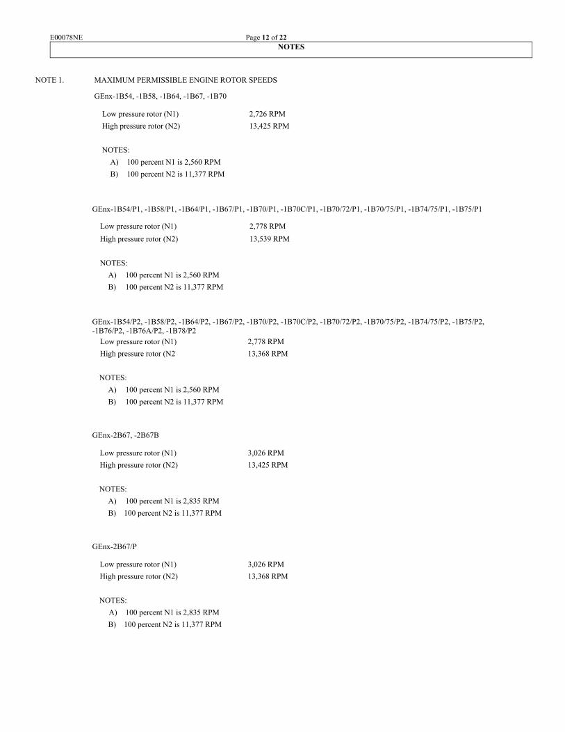
NOTE 1. MAXIMUM PERMISSIBLE ENGINE ROTOR SPEEDS
GEnx-1B54, -1B58, -1B64, -1B67, -1B70
Low pressure rotor (N1) 2,726 RPM
High pressure rotor (N2) 13,425 RPM
NOTES:
A) 100 percent N1 is 2,560 RPM
B) 100 percent N2 is 11,377 RPM
GEnx-1B54/P1, -1B58/P1, -1B64/P1, -1B67/P1, -1B70/P1, -1B70C/P1, -1B70/72/P1, -1B70/75/P1, -1B74/75/P1, -1B75/P1
Low pressure rotor (N1) 2,778 RPM
High pressure rotor (N2) 13,539 RPM
NOTES:
A) 100 percent N1 is 2,560 RPM
B) 100 percent N2 is 11,377 RPM
GEnx-1B54/P2, -1B58/P2, -1B64/P2, -1B67/P2, -1B70/P2, -1B70C/P2, -1B70/72/P2, -1B70/75/P2, -1B74/75/P2, -1B75/P2, -1B76/P2, -1B76A/P2, -1B78/P2 Low pressure rotor (N1) 2,778 RPM
High pressure rotor (N2 13,368 RPM
NOTES:
A) 100 percent N1 is 2,560 RPM
B) 100 percent N2 is 11,377 RPM
GEnx-2B67, -2B67B
Low pressure rotor (N1) 3,026 RPM
High pressure rotor (N2) 13,425 RPM
NOTES:
A) 100 percent N1 is 2,835 RPM
B) 100 percent N2 is 11,377 RPM
GEnx-2B67/P
Low pressure rotor (N1) 3,026 RPM
High pressure rotor (N2) 13,368 RPM
NOTES:
A) 100 percent N1 is 2,835 RPM
B) 100 percent N2 is 11,377 RPM

E00078NE Page 13 of 22
NOTE 2. MAXIMUM PERMISSIBLE TEMPERATURES
GEnx-1B54, -1B58, -1B64 , -1B67, -1B70
Indicated turbine exhaust gas temperature (T49) [see NOTE 5]
Takeoff 5 minutes (see NOTE 12) 1,895°F (1,035°C)
30 seconds Maximum Transient 1,904°F (1,040°C)
Maximum Continuous 1,841°F (1,005°C)
Ground starts (manual or auto) 1,382°F (750°C)
Inflight starts (manual or auto) 1,607°F (875°C)
Inflight starts (high power fuel cut) 1,787°F (975°C)
Oil temperature limits
Continuous 320°F (160°C)
Transient (15 minutes) 350°F (177°C)
GEnx-1B54/P1, -1B58/P1, -1B64/P1, -1B67/P1, -1B70/P1, -1B70C/P1, -1B70/72/P1, -1B70/75/P1, -1B74/75/P1, -1B75/P1
Indicated turbine exhaust gas temperature (T49) [see NOTE 5]
Takeoff 5 minute (see NOTE 12) 1,940°F (1,060°C)
30 seconds Maximum Transient 1,949°F (1,065°C)
Maximum Continuous 1,886°F (1,030°C)
Ground starts (manual or auto) 1,382°F (750°C)
Inflight starts (manual or auto) 1,607°F (875°C)
Inflight starts (high power fuel cut) 1,787°F (975°C)
Oil temperature limits
Continuous 320°F (160°C)
Transient (15 minutes) 350°F (177°C)
GEnx-1B54/P2, -1B58/P2, -1B64/P2, -1B67/P2, -1B70/P2, 1B70C/P2, -1B70/72/P2, -1B70/75/P2, -1B74/75/P2, -1B75/P2, -1B76/P2, -1B76A/P2, -1B78/P2 Indicated turbine exhaust gas temperature (T49) [see NOTE 5]
Takeoff 5 minute (see NOTE 12) 1,949°F (1,065°C)
30 seconds Maximum Transient 1,958°F (1,070°C)
Maximum Continuous 1,886°F (1,030°C)
Ground starts (manual or auto) 1,382°F (750°C)
Inflight starts (manual or auto) 1,607°F (875°C)
Inflight starts (high power fuel cut) 1,787°F (975°C)
Oil temperature limits
Continuous 320°F (160°C)
Transient (15 minutes) 350°F (177°C)
E00078NE Page 14 of 22
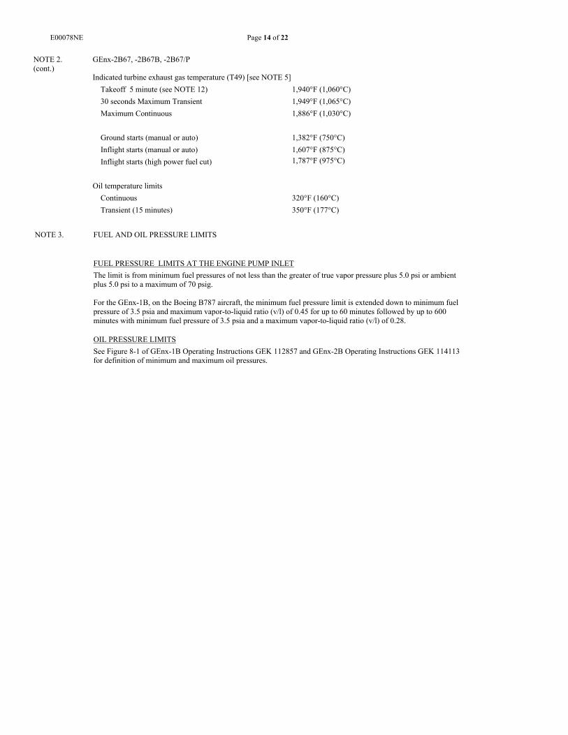
NOTE 3. FUEL AND OIL PRESSURE LIMITS
FUEL PRESSURE LIMITS AT THE ENGINE PUMP INLET
The limit is from minimum fuel pressures of not less than the greater of true vapor pressure plus 5.0 psi or ambient plus 5.0 psi to a maximum of 70 psig. For the GEnx-1B, on the Boeing B787 aircraft, the minimum fuel pressure limit is extended down to minimum fuel pressure of 3.5 psia and maximum vapor-to-liquid ratio (v/l) of 0.45 for up to 60 minutes followed by up to 600 minutes with minimum fuel pressure of 3.5 psia and a maximum vapor-to-liquid ratio (v/l) of 0.28. OIL PRESSURE LIMITS
See Figure 8-1 of GEnx-1B Operating Instructions GEK 112857 and GEnx-2B Operating Instructions GEK 114113 for definition of minimum and maximum oil pressures.
NOTE 2. (cont.)
GEnx-2B67, -2B67B, -2B67/P
Indicated turbine exhaust gas temperature (T49) [see NOTE 5]
Takeoff 5 minute (see NOTE 12) 1,940°F (1,060°C)
30 seconds Maximum Transient 1,949°F (1,065°C)
Maximum Continuous 1,886°F (1,030°C)
Ground starts (manual or auto) 1,382°F (750°C)
Inflight starts (manual or auto) 1,607°F (875°C)
Inflight starts (high power fuel cut) 1,787°F (975°C)
Oil temperature limits
Continuous 320°F (160°C)
Transient (15 minutes) 350°F (177°C)

E00078NE Page 15 of 22
NOTE 4. GEnx ACCESSORY DRIVE CHARACTERISTICS
GEnx-1B54, -1B58, -1B64, -1B67, and -1B70
Accessory Defined By
Rotation (See
Comment A)
Gear Ratio to
Core Rotor
Drive Shaft (RPM)
Maximum Weight
LB (KG)
Maximum Overhung Moment
IN-LB (Nꞏm)
Shear Torque
IN-LB (Nꞏm)
Continuous Pad Rating HP
(Inflight -total for both
VFSG’s)
Overload [HP]
692
VFSG 1 ICNR -GE-BE059
CCW 1.1331 12,891.30 234.4 (106.3) WET
1,718 (194.4) 19,596-20,220 (2,214-2,285)
(Dual Engine) 790
(Single Engine)
See Comment
C
692
VFSG 2 ICNR-GE-BE060
CCW 1.1331 12,891.30 234.4 (106.3) WET
1,718 (194.4) 19,596-20,220 (2,214-2,285)
(Dual Engine) 790
(Single Engine)
See Comment
C
Hydraulic Pump
ICNR-GE-BE057
CCW 0.4438 5,049.10 30.3 (13.74) WET
140 (15.81) WET
2,625-3,715 (297-420)
62 85 [5 sec]
Core Turn
0.5 Square Drive/ Dwg-
2305M71
CCW
0.6773
7,705.60
N. A.
N. A.
N. A.
N. A.
N. A.
Comments:
A. Rotation is defined facing the pad. B. 100 percent engine core speed is 11,377rpm. C. 1,021 HP total both drive pads at flight idle, with no more than 528 HP on any one drive pad for up to 1 second [single engine].
866 HP total both drive pads at flight idle, with no more than 471 HP on any one drive pad for up to 5 minutes [dual engine].

E00078NE Page 16 of 22
NOTE 4. (cont.)
GEnx ACCESSORY DRIVE CHARACTERISTICS (continued)
GEnx-1B54/P1, -1B58/P1, -1B64/P1, -1B67/P1, -1B70/P1, -1B70C/P1, -1B70/72/P1, -1B70/75/P1, -1B74/75/P1, and -1B75/P1
Accessory Defined
By Rotation
(See Comment
A)
Gear Ratio to
Core Rotor
Drive Shaft (RPM)
Maximum Weight
LB (KG)
Maximum Overhung Moment
IN-LB (Nꞏm)
Shear Torque
IN-LB (Nꞏm)
Continuous Pad Rating HP
(Inflight -total for both
VFSG’s)
Overload [HP]
676
VFSG 1 ICNR -GE-BE059
CCW 1.1331 12,891.30 234.4 (106.3) WET
1,718 (194.4) 19,596-20,220 (2,214-2,285)
(Dual Engine) 720
(Single Engine)
See Comment C
676
VFSG 2 ICNR-GE-BE060
CCW 1.1331 12,891.30 234.4 (106.3) WET
1,718 (194.4) 19,596-20,220 (2,214-2,285)
(Dual Engine) 720
(Single Engine)
See Comment C
Hydraulic Pump
ICNR-GE-BE057
CCW 0.4438 5,049.10 30.3 (13.74) WET
140 (15.81) WET
2,625-3,715 (297-420)
62 85 [5 sec]
Core Turn
0.5 Square Drive/ Dwg-
2305M71
CCW
0.6773
7,705.60
N. A.
N. A.
N. A.
N. A.
N. A.
Comments:
A. Rotation is defined facing the pad. B. 100 percent engine core speed is 11,377rpm. C. 1,021 HP total both drive pads at flight idle, with no more than 528 HP on any one drive pad for up to 1 second [single engine].
866 HP total both drive pads at flight idle, with no more than 471 HP on any one drive pad for up to 5 minutes [dual engine].

E00078NE Page 17 of 22
NOTE 4. (cont.)
GEnx ACCESSORY DRIVE CHARACTERISTICS (continued)
GEnx-1B54/P2, -1B58/P2, -1B64/P2, -1B67/P2, -1B70/P2, -1B70C/P2, -1B70/72/P2, -1B70/75/P2, -1B74/75/P2, -1B75/P2, -1B76/P2,
-1B76A/P2 and -1B78/P2
Accessory Defined By
Rotation (See
Comment A)
Gear Ratio to
Core Rotor
Drive Shaft (RPM)
Maximum Weight
LB (KG)
Maximum Overhung Moment
IN-LB (Nꞏm)
Shear Torque
IN-LB (Nꞏm)
Continuous Pad Rating HP
(Inflight -total for both
VFSG’s)
Overload [HP]
676
VFSG 1 ICNR -GE-BE059
CCW 1.1331 12,891.30 234.4 (106.3) WET
1,718 (194.4) 19,596-20,220 (2,214-2,285)
(Dual Engine) 720
(Single Engine)
See Comment C
676
VFSG 2 ICNR-GE-BE060
CCW 1.1331 12,891.30 234.4 (106.3) WET
1,718 (194.4) 19,596-20,220 (2,214-2,285)
(Dual Engine) 720
(Single Engine)
See Comment C
Hydraulic Pump
ICNR-GE-BE057
CCW 0.4438 5,049.10 30.3 (13.74) WET
140 (15.81) WET
2,625-3,715 (297-420)
59 85 [5 sec]
Core Turn
0.5 Square Drive/ Dwg-
2305M71
CCW
0.6773
7,705.60
N. A.
N. A.
N. A.
N. A.
N. A.
Comments:
A. Rotation is defined facing the pad. B. 100 percent engine core speed is 11,377rpm. C. 1,021 HP total both drive pads at flight idle, with no more than 528 HP on any one drive pad for up to 1 second [single engine].
866 HP total both drive pads at flight idle, with no more than 471 HP on any one drive pad for up to 5 minutes [dual engine].

E00078NE Page 18 of 22
NOTE 5. ENGINE RATINGS
Engine ratings are based on calibrated test stand performance under the following conditions:
1. Sea level static, standard pressure (14.696 psia), 59 °F 2. No customer bleed or customer horsepower extraction 3. Ideal inlet, 100% ram recovery 4. Production aircraft flight cowling 5. Production instrumentation 6. Fuel lower heating value of 18,400 BTU/lb
NOTE 4. (cont.)
GEnx ACCESSORY DRIVE CHARACTERISTICS (continued)
GEnx-2B67, -2B67B, and -2B67/P
Accessory Defined by Rotation (See Comment
A)
Gear Ratio to
Core Rotor
Drive Shaft (RPM)
Static Weight
LB
Maximum Overhang Moment IN-LB
Shear Torque
Torque
IDG 747-8 Boeing
engine specification
CCW 0.6696
4654 to
8989 (See Comment C)
IDG 126.8 QAD 5.6
900 9000 + 400 in-lb
(in-lb) 2245 -CONTINUOUS 3575 –TRANSIENT
(See Comment D) 5250 –MOMENTARY
(See Comment E)
HYDRAULIC PUMP
747-8 Boeing engine
specification CCW 0.3157
2194 to
4238 40.1 DRY 261 WET 4550 + 300 in-lb
(in-lb) 1103 - CONTINUOUS 1790 – TRANSIENT
(See Comment F) 4250 – FAILURE (See Comment G)
AIR TURBINE STARTER
M50TF4062 CCW 1.1331 58.4 % N2
(5863 RPM) MAX CUT OUT
49.38 300 1685 ft-lb
(ft-lb) Cold Day
APU Start 617 XBL Start 820
CORE TURN 0.5 SQUARE
DRIVE CCW 0.6012 6839.9 N.A. N.A. N.A. N.A.
Comments: A. Rotation is defined facing the pad B. 100 percent engine core speed is11,377rpm. C. IDG online speed: 4,600 rpm. Load is removed when input remains 4,450 RPM or less for 150 + 50 ms. D. Once every 1,000 engine operating hours. E. Once every 5,000 engine operating hours. F. Peak running torque at engine start and at maximum flow for simultaneous flap and gear operation (takeoff condition). G. Torque experienced during an input shaft shear event.

E00078NE Page 19 of 22
NOTE 6. MAXIMUM PERMISSABLE BLEED AIR EXTRACTION
GEnx-1B54, -1B58, -1B64, -1B67, and -1B70 (applicable to engines not equipped with a booster anti-ice system)
Stage 7 - Percent W25
Any Power Setting 3.3%
GEnx-1B54, -1B58, -1B64, -1B67, -1B70, -1B54/P1, -1B58/P1, -1B64/P1, -1B67/P1, -1B70/P1, -1B70C/P1, -1B70/72/P1, -1B70/75/P1, -1B74/75/P1, -1B75/P1, -1B54/P2, -1B58/P2, -1B64/P2, -1B67/P2, -1B70/P2, -1B70C/P2, -1B70/72/P2, -1B70/75/P2, -1B74/75/P2, -1B75/P2, -1B76/P2, -1B76A/P2 and -1B78/P2 (applicable to engines equipped with a booster anti-ice system)
Percent Corrected Fan Speed (%N1K) Stage 7 - Percent W25
0 to 31.3 5.0%
31.3 to 66.4 4.7%
> 66.4 3.3%
Comments: A. 100% engine fan speed is 2,560 RPM B. 3.3% W25 is the maximum flow delivered to the engine inlet anti-ice system at any power setting.
GEnx-2B67, -2B67B
%N1K CDP Bleed Percent W25 %N1K S4 Bleed Percent W25
T2 > 67ºF T2 < 67ºF 0 7.28%
0 13 13 15.9 7.28%
81.1 13 13 21.2 7.28%
81.1 8 10 50.0 7.28%
88.2 8 10 50.0 7.85%
88.2 8 8.5 75.8 7.85%
91.7 8 8.5 75.8 7.65%
91.7 8 8 81.1 7.65%
120.0 8 8 84.7 7.85%
91.7 7.85%
NOTE: 100% engine fan speed is 2,835 RPM 108.6 6.00%
108.6 5.00%
120.0 5.00%
GEnx-2B67/P
%N1K CDP Bleed Percent W25 %N1K S4 Bleed Percent W25
T2 > 67ºF T2 < 67ºF 0 7.28%
0 13 13 15.9 7.28%
81.1 13 13 21.2 7.28%
81.1 8 10 50.0 7.28% 88.2 8 10 50.0 7.85%
88.2 8 8.5 64.6 7.85%
91.7 8 8.5 64.6 7.60%
91.7 8 8 77.8 7.60%
120.0 8 8 77.8 7.39%
95.9 7.39%
NOTE: 100% engine fan speed is 2,835 RPM 108.6 6.00%
108.6 5.00%
120.0 5.00%

E00078NE Page 20 of 22
NOTE 7. FUEL
Refer to GEnx-1B Service Bulletin 73-0001 and GEnx-2B Service Bulletin 73-0001 for detailed information pertaining to fuels and additives. These Service Bulletins cover the eligible fuels listed per GE Aviation Specification D50TF2. Eligible fuel classifications are: Class A – Aviation Kerosene Class C – Low Freeze Kerosene Class D – High Flash Kerosene Class E – Low Flash Kerosene
NOTE: Class B – (Jet B, JP4) is prohibited
NOTE 8. LIFE LIMITS
Life limits for critical rotating components for the GEnx-1B54, -1B58, -1B64, -1B67, -1B70, -1B54/P1, -1B58/P1, -1B64/P1, -1B67/P1, -1B70/P1, -1B70C/P1, -1B70/72/P1, -1B70/75/P1, -1B74/75/P1, -1B75/P1, -1B54/P2, -1B58/P2, -1B64/P2, -1B67/P2, -1B70/P2, -1B70C/P2, -1B70/72/P2, -1B70/75/P2, -1B74/75/P2, -1B75/P2, -1B76/P2, -1B76A/P2 and -1B78/P2 are published in Chapter 5 of the GEnx Engine Manual, GEK 112851. The GEnx-2B67, -2B67B, and -2B67/P cyclic life limits are published in Chapter 5 of the GEnx Engine Manual GEK 114119. The GEnx-1B and GEnx-2B cyclic life limits are based on a commercial mission cycle, which consists of a start, takeoff, climb, cruise, descent, and landing. Use (or non-use) of a fan reverser for braking during landing does not affect cycle counts. Each of the following constitutes one cycle: (1) a flight consisting of a takeoff and landing, (2) a touch-and-go landing or simulated touch-and-go landing (no weight on wheels) for pilot training.
NOTE 9. THRUST SETTING PARAMETER
Power setting, power checks, and control of engine thrust output in all operations are based on Fan Speed (N1). Speed sensors are included in the engine assembly for this purpose.
NOTE 10. ICING CONDITIONS
Requirements and limitations for ground operation in icing conditions are specified in: Operating Instructions GEK 112857 for the GEnx-1B54, -1B58, -1B64, -1B67, -1B70, -1B54/P1, -1B58/P1, -1B64/P1, -1B67/P1, -1B70/P1, -1B70C/P1, -1B70/72/P1, -1B70/75/P1, -1B74/75/P1, -1B75/P1,-1B54/P2, -1B58/P2, -1B64/P2, -1B67/P2, -1B70/P2, -1B70C/P2, -1B70/72/P2, -1B70/75/P2, -1B74/75/P2, -1B75/P2, -1B76/P2, -1B76A/P2 and -1B78/P2 Operating Instructions GEK 114113 for the GEnx-2B67, -2B67B, and -2B67/P.
NOTE 11. NEGATIVE G OPERATION
During "negative-G" operation only, it is permissible to operate below minimum oil pressure for a maximum of 15 seconds, as specified in: GEnx Operating Instructions, GEK 112857, Section 8, for the GEnx-1B54, -1B58, -1B64, -1B67, -1B70, -1B54/P1, -1B58/P1, -1B64/P1, -1B67/P1, -1B70/P1, -1B70C/P1, -1B70/72/P1, -1B70/75/P1, -1B74/75/P1, -1B75/P1, -1B54/P2, -1B58/P2, -1B64/P2, -1B67/P2, -1B70/P2, -1B70C/P2, -1B70/72/P2, -1B70/75/P2, -1B74/75/P2, -1B75/P2, -1B76/P2, -1B76A/P2 and -1B78/P2 minimum oil pressure definition. GEnx Operating Instructions, GEK 114113, Section 8, for the GEnx-2B67, -2B67B, and -2B67/P minimum oil pressure definition.
NOTE 12. TAKEOFF TIME LIMIT
The normal 5-minute takeoff time limit may be extended to 10 minutes for engine out contingency.

E00078NE Page 21 of 22
NOTE 13. TIME LIMITED DISPATCH CRITERIA
Criteria pertaining to the engine control systems’ dispatch and maintenance requirements are specified in: For the GEnx-1B54, -1B58, -1B64, -1B67, -1B70, -1B54/P1, -1B58/P1, -1B64/P1, -1B67/P1, -1B70/P1, -1B70C/P1, -1B70/72/P1, -1B70/75/P1, -1B74/75/P1, -1B75/P1, -1B54/P2, -1B58/P2, -1B64/P2, -1B67/P2, -1B70/P2, -1B70C/P2, -1B70/72/P2, -1B70/75/P2, -1B74/75/P2, -1B75/P2, -1B76/P2, -1B76A/P2 and -1B78/P2 engine models: General Electric FADEC Control System Time Limited Dispatch Summary Document, GEK 112858, and the Airworthiness Limitations Section of the GEnx Engine Manual, GEK 112851, which define the various configurations and maximum operating intervals. For the GEnx-2B67, -2B67B, and -2B67/P engine models: General Electric FADEC Control System Time Limited Dispatch Summary Document, GEK 114112, and the Airworthiness Limitations Section of the GEnx Engine Manual, GEK 114119, which define the various configurations and maximum operating intervals.
NOTE 14. Deleted.
NOTE 15. FAN BLADE REPAIR
Approval of repairs of the fan blade composite material in the root section of the fan blade up to the inner annulus flow path line must be coordinated with the FAA Engine Certification Office. Substantiation of the repairs must show that compliance to GEnx-1B Special Condition No. 33-006-SC or GEnx-2B Special Condition No. 33-007-SC is maintained.
NOTE 16. EXHAUST EMISSIONS AND FUEL VENTING
The following emissions standards promulgated in 14 CFR part 34, amendment 5, effective December 31, 2012, and 40 CFR part 87, effective July 18, 2012, have been complied with for: GEnx-1B54, -1B58, -1B64, -1B67, -1B54/P1, -1B58/P1, -1B64/P1, -1B67/P1 as well as GEnx-2B67 and -2B67B. Fuel Venting Emission Standards: 14 CFR 34.10(a) and 34.11; in addition, 40 CFR 87.10(a) and 87.11. Smoke Number (SN) Emission Standards: 14 CFR 34.21(e)(2); in addition, 40 CFR 87.23(c)(l). Carbon Monoxide (CO) Emission Standards: 14 CFR 34.21(d)(l)(ii); in addition, 40 CFR 87.23(c)(l). Hydrocarbons (HC) Emission Standards: 14 CFR 34.21(d)(1)(i); in addition, 40 CFR 87.23(c)(l). Oxides of Nitrogen (NOx) Emission Standards: 14 CFR 34.23(b)(l); in addition, 40 CFR 87.23(c)(3). The following emissions standards promulgated in 14 CFR part 34, amendment 5A, effective October 23, 2013, and 40 CFR part 87, effective July 18, 2012, have been complied with for: GEnx-1B70, -1B70/P1, 1B70C/P1, -B70/72/P1, -1B70/75/P1, -1B74/75/P1, -1B75/P1, -1B54/P2, -1B58/P2, -1B64/P2, -1B67/P2, -1B70/P2, -1B70C/P2, -1B70/72/P2, -1B70/75/P2, -1B74/75/P2, -1B75/P2, -1B76/P2, -1B76A/P2, -1B78/P2 and -2B67/P . Fuel Venting Emission Standards: 14 CFR 34.10(a) and 34.11; in addition, 40 CFR 87.10(a) and 87.11. Smoke Number (SN) Emission Standards: 14 CFR 34.21(e)(2); in addition, 40 CFR 87.23(c)(l). Carbon Monoxide (CO) Emission Standards: 14 CFR 34.21(d)(l)(ii); in addition, 40 CFR 87.23(c)(l). Hydrocarbons (HC) Emission Standards: 14 CFR 34.21(d)(1)(i); in addition, 40 CFR 87.23(c)(l). Oxides of Nitrogen (NOx) Emission Standards: 14 CFR 34.23(b)(l); in addition, 40 CFR 87.23(c)(3). In addition to the FAA's finding of compliance based on the certification requirements defined in this TCDS, the engine manufacturer has declared that the ICAO emissions standards identified in Annex 16, Volume II , Third Edition, Part Ill, Chapter 2, Section 2.2.2 for SN, Section 2.3 .2 for CO and HC, Section 2.3.2.e.3 for NOx (also known as CAEP/8), and Part II Chapter 2 for fuel venting have also been demonstrated. The GEnx-1B54, -1B58, -1B64, -1B67, and -1B70 engine models (defined by the G01 and G02 model lists) for the B787-8 aircraft, and the GEnx-2B67 (defined by the GEnx-2B67G01 and GEnx-2B67G02 model lists) for the B747-8 aircraft will not support the installation of the flow split valve fuel accumulator system. Fuel accumulator system installation is required in order to eliminate post-engine shutdown intermittent fuel releases and observed vapors.

E00078NE Page 22 of 22
NOTE 17. INDUCTION SYSTEM ICING
Demonstration of compliance to 14 CFR part 33, section 33.68, Induction System Icing, is installation specific to the Boeing B787 model aircraft for the GEnx-1B54, -1B58, -1B64, -1B67, -1B70, -1B54/P1, -1B58/P1, -1B64/P1, -1B67/P1, -1B70/P1, -1B70C/P1, -1B70/72/P1, -1B70/75/P1, -1B74/75/P1, -1B75/P1, -1B54/P2, -1B58/P2, -1B64/P2, -1B67/P2, -1B70/P2, -1B70C/P2, -1B70/72/P2, -1B70/75/P2, -1B74/75/P2, -1B75/P2, -1B76/P2, -1B76A/P2 and -1B78/P2 engine models, and B747-8 and B747-8F for the GEnx-2B67, -2B67B, and -2B67/P engine models. Installation of these engine models on different airplane models or type will require a separate evaluation and finding of compliance to section 33.68.
NOTE 18. Deleted.
NOTE 19. Deleted
NOTE 20. Deleted.
NOTE 21. EXTENDED TWIN ENGINE OPERATIONS (ETOPS)
The GEnx-1B54, -1B58, -1B64, -1B67, and -1B70 engine models (defined by the G03, G04 and G05 model lists), the GEnx-1B54/P1, -1B58/P1, -1B64/P1, -1B67/P1, -1B70/P1, -1B70C/P1, -1B70/72/P1, -1B70/75/P1, -1B74/75/P1, -1B75/P1, -1B54/P2, -1B58/P2, -1B64/P2, -1B67/P2, -1B70/P2, -1B70C/P2, -1B70/72/P2, -1B70/75/P2, -1B74/75/P2, -1B75/P2, -1B76/P2, -1B76A/P2 and -1B78/P2 engine models comply with the requirements of 14 CFR part 33, sections 33.4, Appendix A, A33.3(c), 33.71(c)(4), and 33.201, and are therefore eligible for installation on ETOPS and Early ETOPS approved airplanes. The demonstrated diversion time is 330 minutes at maximum continuous power plus 15 minutes at hold and go-around power. ETOPS eligibility does not constitute airplane or operational level approvals necessary to conduct ETOPS flights.
For the GEnx-1B54, -1B58, -1B64, -1B67, -1B70, -1B54/P1, -1B58/P1, -1B64/P1, -1B67/P1, -1B70/P1, 1B70C/P1, -1B70/72/P1, -1B70/75/P1, -1B74/75/P1, and -1B75/P1, -1B54/P2, -1B58/P2, -1B64/P2, -1B67/P2, -1B70/P2, -1B70C/P2, -1B70/72/P2, -1B70/75/P2, -1B74/75/P2, -1B75/P2, -1B76/P2, -1B76A/P2 and -1B78/P2 engine models installed on B787 aircraft, the engine fuel pump must be replaced prior to the next ETOPS flight after any single suction feed operation event of duration greater than 30 minutes. Suction feed operation is defined by engine pump inlet fuel pressure less than the greater of true vapor pressure plus 5.0 psi or ambient plus 5.0 psi.
NOTE 22. Deleted.
….. END …..