Highway Construction - Constrofacilitator
22
FOLLOW US Highway pavement components Structural layers of highway pavements Superelevation in highway Gradients used on roads Highway Camber Highway curves eMAGAZINE www.constrofacilitator.com JULY 2021 Volume-03 eM-07 Knowledge and b2b portal for construction and infrastructure Constrofacilitator
-
Upload
khangminh22 -
Category
Documents
-
view
0 -
download
0
Transcript of Highway Construction - Constrofacilitator

FOLLOW USFOLLOW US
Highway pavement components
Structural layers of highway pavements
Superelevation in highway
Gradients used on roads
Highway Camber
Highway curves
eMAGAZINEwww.constrofacilitator.comJULY 2021
Volume-03 eM-07
Knowledge and b2b portal for construction and infrastructure
Constrofacilitator

HIGHWAY CONSTRUCTION
Highway design involves the consideration of three major factors (human, vehicular, and roadway) and how these factors interact to provide a safe highway. The management of the highway construction involves the application of engineering, technical and management practices to optimise the level-of-service outcome in return for the most cost-e�ective input. The main objective is to apply the right treatment at the right time to achieve the desired level of service.
The multipurpose characteristics of highways, economic environment, and the advances in highway pricing technology are constantly changing. In this edition of eMagazine we have covered topics such as di�erent types of gradients used on roads, types of highway curves, components of highway pavement construction, structural layers and types of highway pavements, camber in highway construction and super elevation in highway construction.
2 July 2021 • Constrofacilitator

3
Different components of highway pavement construction
Different types of gradients used on roads
Different types of highway curves
The use of Camber in highway construction
Superelevation in highway construction
Structural layers and types of highway pavements
News
04
06
09
14
16
11
18
4
9 11
6
Constrofacilitator • July 2021

Factors to Consider for Road Gradi-
ent
Ÿ The type of road surface
Ÿ Drainage required
Ÿ Nature of the ground
Ÿ Nature of the traffic
Ÿ Safety Required
Ÿ Road and railway interaction
Ÿ Bridge Approaches
Ÿ The total height to be covered
Different types of road gradients
Ruling gradient
The ruling gradient or the design gradi-
ent is the maximum gradient with
which the designer attempts to design
the vertical profile of the road. This
depends on the terrain, length of the
grade, speed, pulling power of the vehi-
cle and the presence of the horizontal
curve. In flatter terrain, it may be possi-
ble to provide flat gradients, but in hilly
terrain it is not economical and some-
road gradient is a lon-
Agitudinal slope pro-
vided to the formation
level of a road along its
alignment. “Gradient of
Road is defined as the
rate of rising or falls along the length of
the road with respect to the horizontal
alignment”. It is the verticality experi-
enced during travel, spread over the
Corresponding horizontal distance.
Mostly the land topography is not
straight, with a changing magnitude, it
is quite common to have slopes. Con-
structing a road on such land can result
in mishaps. With the help of road gra-
dients, these elevation-changes are
smoothened out. It is an essential com-
ponent of constructing roads, as they
govern every aspect of the connection
between the flat segments of roads.
They are the solutions to changes in ele-
vation, adequate drainage, controlling
costs of construction, and managing
any public issues.
times not possible also. The ruling gra-
dient is adopted by the designer by con-
sidering a particular speed as the
design speed and for a design vehicle
with standard dimensions.
Limiting gradient
This gradient is adopted when the rul-
ing gradient results in enormous
increase in cost of construction. On roll-
Different types of gradients used on
roads
GRADIENTS USED ON ROADS
04 July 2021 • Constrofacilitator

ing terrain and hilly terrain it may be fre-
quently necessary to adopt a limiting
gradient. But the length of the limiting
gradient stretches should be limited
and must be sandwiched by either
straight roads or easier grades.
Exceptional gradient
Exceptional gradients are very steeper
gradients given at unavoidable situa-
tions. They should be limited for short
stretches not exceeding about 100
metres at a stretch. In mountainous
and steep terrain, successive excep-
tional gradients must be separated by
a minimum 100 metre length gentler
gradient.
Minimum gradient
Minimum gradient is used at locations
where surface drainage is important.
Camber will take care of the lateral
drainage. But the longitudinal drainage
along the side drains require some
slope for smooth flow of water. There-
fore minimum gradient is provided for
drainage purposes and it depends on
the rain fall, type of soil and other site
05July 2021 • Constrofacilitator
GRADIENTS USED ON ROADS
The road gradient
is pivotal for vehicles
to travel between different
levels of elevation
smoothly.
For adequate drainage,
road gradients are important,
as without it the water would
steadily stagnate.
The side drains'
construction is also dependent
on it as the slope dictates the
direction that the water would
flow towards it.
Road gradient
minimises substantial cutting
or embankment by developing
road gradient similar to the
existing ground
Vertical gradients are
used to reprofile two or more
vertical gradients of varying
range with the help of
crest or sag curves
Connects the two
stations or points with each
other, which are located at
different levels
Allows movement of
the vehicle on the vertical
curves smoothly
Helps to drain off
rainwater from the
surface of the roads
Advantages
of Road
Gradient
conditions. A minimum of 1 in 500 may
be sufficient for concrete drain and 1 in
200 for open soil drains are found to
give satisfactory performance.
Average gradient
It is the ratio of total rise or fall to the
horizontal distance between any two
points along the alignment of the road.
Floating gradient
The gradient on which a motor vehicle
moving with a constant speed contin-
ues to descend with the same speed
without any application of power
brakes is called floating gradient.
Conclusion
Before finalizing the gradients, the con-
struction cost, vehicular operation cost
and the practical problems in the site
also have to be considered. Usually
steep gradients are avoided as far as
possible because of the difficulty to
climb and increase in the construction
cost.

Different types of highway curves
highway curve is an arc
Awhich connects two straight lines which are separated by some angle called deflection angle. This situation
occurs where the alignment of a road-way or railway changes its direction because of unavoidable objects or con-ditions. There are two types of curves in highway construction which range from horizontal curve and vertical curve. Curves are provided whenever a road changes its direction from right to S (vice versa) or changes its alignment from up to down (vice versa). Curves are a critical element in the pavement design. They are provided with a maxi-mum speed limit that should be fol-lowed very strictly. Following the speed limit becomes essential as the exceed
may be a higher chance of occur-ring accidents due to overspend-ing, or drowsy driving.
Ÿ If the curvature is provided the driver gets conscious and controls his speed and drowsiness while driving.
Ÿ Drowsiness is the main cause of accidents on highways, if curve is provided on the highway the driver becomes alert and respond to the curvature
Ÿ Gradual change in direction or ori-entation in the alignment can be made by providing the curves.
Ÿ Road curves are provided so as to get comfort to the passengers.
Ÿ Gradual change in the direction or orientation in the alignment can be made by providing the curves.
Ÿ Curves are provided so as to get
in speed may lead to the chances of the vehicle becoming out of control while negotiating a turn and thus increase the odds of fatal accidents. Also, it is very necessary that appropri-ate safety measures be adopted at all horizontal and vertical curves to make the infrastructure road user friendly and decrease the risks of hazardous cir-cumstances.
Importance of curves in highway
Ÿ If there is a sudden obstruction in the mid way of the highway such as mountains, Rocks etc.. which are impossible to move so a gradual curvature is provided to move for-ward towards the destination.
Ÿ Highways are generally straight roads for longer lengths so there
Constrofacilitator • July2021 06
HIGHWAY CURVES

easy turning in case of road and track
Different types of highway curves
There are two types of curves- Horizon-tal and Vertical curves. Each of them comes with various subcategories, each of them is explained below.
Horizontal curves
The curve provided in the horizontal plane of ground or earth is called a hori-zontal curve. It connects two straight lines which are in the same level but having different or the same directions. There are different types of horizontal curves, each of them is explained below.
Simple circular curve - It is a curve con-sisting of a single arc with a constant radius connecting the two tangents. It is a type of horizontal curve used most in common. A simple arc provided in the road or railway track to impose a curve between the two straight lines is the simple circular curve. The smaller is the degree of curve, the flatter is the
curve and vice versa. The sharpness of a simple curve is also determined by radius R. Large radius are flat whereas small radius are sharp. A simple curve is normally represented by the length of its radius or by the degree of curve.
Compound curve - It is a curve made up of two or more circular arcs of suc-cessively shorter or longer radii, joined tangentially without reversal of curva-ture, and used on some railroad tracks and highways as an easement curve to provide a less abrupt transition from tangent to full curve or vice versa. Since their tangent lengths vary, compound curves fit the topography much better than simple curves. These curves eas-ily adapt to mountainous terrain or areas cut by large, winding rivers. How-ever, since compound curves are more hazardous than simple curves, they should never be used where a simple curve will do.
Reverse curve - A reverse curve is com-posed of two or more simple curves turning in opposite directions. Their points of intersection lie on opposite ends of a common tangent, and the PT
of the first curve is coincident with the PC of the second. This point is called the point of reverse curvature (PRC). A reverse curve is composed of two arcs of equal or different radii bending or curving in opposite directions with com-mon tangent at their junction, their cen-ters being on opposite sides of the curve.
Track transition curve - A track transi-tion curve, or spiral easement, is a mathematically-calculated curve on a section of highway, in which a straight section changes into a curve. It is designed to prevent sudden changes in lateral In plane (viewed from above), the start of the transition of the horizon-tal curve is at infinite radius, and at the end of the transition, it has the same radius as the curve itself and so forms a very broad spiral. At the same time, in the vertical plane, the outside of the curve is gradually raised until the cor-rect degree of bank is reached.
Spiral curve - Spiral curves are gener-ally used to provide a gradual change in curvature from a straight section of road to a curved section. They assist
Constrofacilitator • July 202107
HIGHWAY CURVES
Horizontal curves

the driver by providing a natural path to follow. Spiral curves also improve the appearance of circular curves by reducing the break in alignment per-ceived by drivers. The use of a spiral is about making the road or track follow the same form that the vehicle naturally takes. In a car, you don't go directly from going straight to fully turning. There is a transition area where you slowly turn the steering wheel. On high-ways, the lanes are wide enough that you can drive a spiral just by moving from one side of the lane to the other.
Vertical curves
These curves are provided to change the slope in the road and may or may not be symmetrical. They are parabolic and not circular like horizontal curves. Identifying the proper grade and the safe passing sight distance is the main design criterion of the vertical curve, crest vertical curve the length should be enough to provide safe stopping sight distance and in sag vertical curve the length is important as it influences the factors such as headlight sight dis-
tance, rider comfort and drainage requirements. There are two types of vertical curves discussed below.
Valley/ Sag Curve - Valley curves or sag curves are vertical curves with con-vexity downwards. In valley curves, the centrifugal force will be acting down-wards along with the weight of the vehi-cle, and hence impact to the vehicle will be more. This will result in jerking of the vehicle and cause discomfort to the passengers. Thus the most important design factors considered in valley curves are- impact-free movement of vehicles at design speed and avail-ability of stopping sight distance under headlight of vehicles for night driving. The valley curve is made fully transi-tional by providing two similar transition curves of equal length.
Summit curve - Summit curves are ver-tical curves with gradient upwards. Sight distance requirements for the safety is most important on summit curves. The stopping sight distance or absolute minimum sight distance should be provided on these curves
Constrofacilitator • July2021 08
HIGHWAY CURVES
Vertical Curves
and where overtaking is not prohibited, overtaking sight distance or intermedi-ate sight distance should be provided as far as possible. When a fast moving vehicle travels along a summit curve, there is less discomfort to the passen-gers. This is because the centrifugal force will be acting upwards while the vehicle negotiates a summit curve which is against the gravity and hence a part of the tyre pressure is relieved. Also if the curve is provided with ade-quate sight distance, the length would be sufficient to ease the shock due to change in gradient.
Conclusion
The curves play a vital role in the geo-metric design of highway alignments, so it must be properly designed so as to provide safety, comfort and conve-nience at the time of driving the vehi-cles or train on road curves. he design of the curve is dependent on the intended design speed for the road-way, as well as other factors including drainage and friction.

ifferent components of a
Dhighway play an impor-tant part in ensuring the safety and service life of a road. The components of a road are designed to meet the design and func-
tional requirements. These geometric com-ponents are designed in accordance with the traffic of the region. Design and geome-try of various cross-sectional elements are important aspects to be considered in this regard. Given below are different compo-nents that need to be considered for high-way construction.
Components of highway construction
Carriageway
A carriageway generally consists of a num-ber of traffic lanes together with any associ-
Different components of highway pavement construction
ated shoulder, but may be a sole lane in width. Traffic lines are those lines on which traffic can move freely without any restric-tion. The carriageway is divided into a single carriageway and a dual carriageway. A sin-gle carriageway road has one carriageway with 1, 2 or more lanes together with any as-sociated footways and road verges A dual carriageway road has two roadways sepa-rated by a central reservation.
Cross slope
Cross slope, cross fall or camber is a geo-metric feature of pavement surfaces: the transverse slope with respect to the horizon. It is a very important safety factor. Cross slope is provided to provide a drainage gra-dient so that water will run off the surface to a drainage system such as a street gutter or ditch. Inadequate cross slope will contribute to aquaplaning. On straight sections of nor-mal two-lane roads, the pavement cross sec-tion is usually highest in the center and drains to both sides. In horizontal curves, the cross slope is banked into super eleva-tion to reduce steering effort and lateral force required to go around the curve.
9 July 2021 • Constrofacilitator
HIGHWAY PAVEMENT CONSTRUCTION

Medians
The median strip or central reservation is the reserved area that separates opposing lanes of traffic on divided roadways, such as divided highways, dual carriageways, free-ways, and motorways. They are physical or painted separation provided to separate two road ways. Mainly used to differentiate vehicles based on speed. They are a pedes-trian benefit, because they can serve as a place of refuge for pedestrians who cross a street midblock or at intersections. They pro-vide space for street trees and other land-scaping which, in turn, can help reduce speeds by changing the character of a street. They also have benefits for motorist safety when they replace center turn lanes. Desired turning movements need to be care-fully provided so that motorists are not forced to travel on inappropriate routes such as residential streets or an unsafe U-turn condition is not created.
Kerbs
A kerb is a vertical or sloping member pro-vided along the edge of a pavement or Shoulder to give strength and protect the edge of the pavement. In highway engineer-ing, it indicates the boundary between the pavement and shoulder or sometimes is-land or footpath or car parking space. They are designed to discourage vehicles from leaving the pavement. They are provided when there is a considerable amount of pe-destrian traffic. They are placed at a height
of 20 cm above the pavement edge with a steep batter. They are generally constructed of cut stone or cement concrete slabs. The kerb and the road surface near the edge to-gether form a side-channel which carries rainwater that comes from the road surface.
Road margins
Road margin is the portion of the road be-yond the carriageway and on the roadway can be generally called road margins. Vari-ous elements that form the road margins in-clude
Ÿ ShouldersŸ Parking linesŸ Bus bayŸ Service roadsŸ Cycle trackŸ FootpathŸ Guard rail
Width of carriage way
Width of the carriageway or the width of the pavement depends on the width of the traf-fic lane and number of lanes. Width of a traf-fic lane depends on the width of the vehicle and the clearance. Side clearance improves operating speed and safety. The maximum permissible width of a vehicle is 2.44 and the desirable side clearance for single lane traffic is 0.68 m.
Width of roadway
Width of formation or roadway width is the sum of the widths of pavements or carriage-way including separators and shoulders. This does not include the extra land in for-mation/cutting.
Right of way
Right of way (ROW) or land width is the width of land acquired for the road, along its alignment. It should be adequate to accom-modate all the cross-sectional elements of the highway and may reasonably provide for future development. Factors influencing the width of ROW.
Ÿ Width of formationŸ Embankment depth and cutting depthŸ Side slopes of embankment or cuttingŸ Drainage systemŸ Site distance considerationsŸ Future widening & Service roads.
Drainage
The pavement surface should be absolutely impermeable to prevent seepage of water into the pavement layers. Further, both the geometry and texture of pavement surface should help in draining out the water from the surface in less time.
Conclusion
All the components as described above should be used in accordance to the topog-raphy and functional requirements to get a well performing highway.
10July 2021 • Constrofacilitator
HIGHWAY PAVEMENT CONSTRUCTION

Structural layers and types of highway pavements
highway pavement con-
Asists of layers of pro-cessed materials above the natural soil subgrade, whose primary function is to distribute the applied
vehicle loads to the sub-grade. The pave-ment structure should be able to provide a surface of acceptable riding quality, ade-quate skid resistance, favorable light reflecting characteristics, and low noise pollution. It has to be constructed based on the traffic requirements, climatic con-ditions of the area, terrain, etc.
Requirements of highway pavement
The primary function of a pavement is to
stresses imposed upon itŸ Adequate coefficient of friction to
prevent skidding of vehicles,Ÿ Smooth surface to provide comfort
to road usersŸ Impervious surface, so that sub-
grade soil is well protectedŸ Long design life with low mainte-
nance costŸ Thickness should be adequate to
transmit the applied loads and dis-tribute them on to a larger area of the soil below
Ÿ Hard wearing surface so as to resist the abrasion caused by vehicle tyres.
Structural layers of highway pave-ment
transmit loads to the sub-base and under-lying soil. Modern flexible pavements con-tain sand and gravel or crushed stone compacted with a binder of bituminous material, such as asphalt, tar, or asphaltic oil. Such a pavement has enough plastic-ity to absorb shock. Rigid pavements are made of concrete, composed of coarse and fine aggregate and portland cement, and usually reinforced with steel rod or mesh. An ideal pavement should meet the following requirements:
Ÿ Right thickness to distribute the wheel load stresses to a safe value on the sub-grade soil
Ÿ Durable to withstand all types of
Constrofacilitator • July 202111
HIGHWAY PAVEMENTS

Base course
It is below the surface course and its func-tion is to distribute the stresses transmit-ted through the surface course evenly onto the layers below. Invariably, it con-sists of granular or bituminous material, and acts as a structural part of the pave-ment. The base course is the most impor-tant layer of a road structure which trans-fers the stresses developed due to traffic impacts through the wearing course. The base course layer provides the required foundation stiffness and structural strength.
Surface Course
It is the topmost layer; its function is to provide a smooth, strong, abrasion-resistant and reasonably impervious course. Since it is directly in contact with the vehicle tyres, it has to resist the imposed wheel loads and transmit them safely to the layer below. The material may be granular, bituminous or cement concrete depending upon the nature of the construction. For flexible pavements, the bituminous surface is the wearing course whereas in rigid pavement the con-crete surface act as the base course cum wearing course.
Sub-Base Course
It is just below the base course and pro-vides additional help to the courses above it in distributing the loads. It also helps in preventing soil grains of the subgrade from intruding into the base course above, and counteracts frost action, if any. It may consist of stabilised soil or soil aggregate mixes, which facilitate drain-
age of free water from the pavement. It comes between the base course and subgrade. The material used for this layer shall satisfy the specifications in terms of gradation, strength, and plastic character-istics. This layer is necessary if the subgrade is of poor quality.
Subgrade
It is the compacted natural soil immedi-ately below the pavement layers; this act as a foundation for the highway. The top surface of the subgrade is called the for-mation level. Based on the alignment and the nature of the terrain, a roadway may be constructed over an embankment or a cutting, or at or nearly at the natural ground level. The formation of level, therefore, has to be properly decided to suit these conditions. It serves as the foun-dation and acts as a uniform support to pavements. Sub grades bear the entire load of the payments along with the ser-vice load of traffic.
Different types of highway pave-ments
Flexible pavements
Flexible pavements have base courses of
broken stone pieces either compacted into place together with bitumen to form asphalt. These can be either in the form of pavement surface treatments (such as a bituminous surface treatment (BST) gen-erally found on lower volume roads) or, HMA surface courses (generally used on higher volume roads such as the Inter-state highway network). These types of pavements are called “flexible” since the total pavement structure “bends” or “de-flects” due to traffic loads. A flexible pave-ment structure is generally composed of several layers of materials which can accommodate this “flexing”. The vertical compressive stress is maximum on the pavement surface directly under the wheel load and is equal to the contact pressure under the wheel. The lower lay-ers of pavement have to take up only lesser magnitudes of stresses and there is no direct wearing action due to traffic loads and weathering action due to envi-ronmental factors. Therefore inferior materials with lower cost can be used in the lower layers. The top layer has to be the strongest as the highest compressive stresses are to be sustained by this layer, in addition to the wear and tear due to the moving traffic and varying factors due to weather.
Types of Flexible Pavements
Ÿ Conventional layered flexible pave-ment
Ÿ Full - depth asphalt pavementŸ Contained rock asphalt mat (CRAM)
HIGHWAY PAVEMENTS
Constrofacilitator • June2021 12

Rigid pavements
Rigid pavements are those which possess noteworthy flexural strength of flexural strength or flexural rigidity. The basic design of rigid pavement is very simple. A surface layer, made up of slabs of Port-land cement concrete (PCC), sits on top of a handful of sub-layers. The layer directly under the PCC is more flexible than the concrete, but still quite rigid. This layer pro-vides a stable base for the PCC as well as assists in drainage. Some roads have a sec-ond sublayer under the first that is even more flexible, while some simply have the existing soil.
Types of Rigid Pavements
Ÿ Jointed plain concrete pavement (JPCP)
Ÿ Jointed reinforced concrete pave-ment (JRCP)
Ÿ Continuous reinforced concrete pave-ment (CRCP)
Ÿ Prestressed concrete pavement (PCP)
Semi-rigid pavement
A semi-rigid pavement is intermediate between the flexible and the rigid types.The semi-rigid pavement is a com-posite pavement material consisting a porous asphalt concrete (PAC) with air voids which is filled or flooded by a special formulated high performance polymer modified cement mortar grouting material.It is the combination the charac-teristics of Porous Asphalt Concrete (PAC) and Portland cement concrete (PCC) pave-ment. The semi-rigid pavement consists
of two main components which are porous asphalt concrete (PAC) and the high performance polymer modified cement mortar grouting material.
Composite pavement
A composite pavement is a type of pave-ment that utilizes both asphalt and con-crete. Typically, a concrete base layer pro-vides structural capacity while an asphalt surface layer provides a wearing surface course. This pavement type can also be used in conjunction with roller com-pacted concrete (RCC) pavements, where the RCC pavement provides the structural capacity that the conventional concrete pavement base would.
Conclusion
The performance of the highway pave-ment depends on the correct usage of structural layer as per fitted with pave-ment types as discussed above. Pavement performance is an important issue in the operation and planning of highway engi-neering. There are several factors that
affect pavement performance, such as traffic, soil, environmental, economic and stress distribution factors. Go for an expe-rienced pavement engineer to meticu-lously manage the operation efficiency desired from highway pavement.
References:-
wirtgen-group.comcivil.businessconstructioncivil.comgeosynthetica.comchemilink.com
Constrofacilitator • July 202113
HIGHWAY PAVEMENTS

amber is defined as a cross
Cslope that is provided to raise the middle of the road surface in order to drain off the water from the road sur-
face. It is the slope provided to the road surface at the transverse direction to drain off the rainwater out of the road surface. It is also known as the cross slope of the highway. It is provided in such a way that the center of the car-riageway is raised with respect to the edges, forming the highest point.
Why use camber
Ÿ Prevent the entry of the surface water into the subgrade soil through the pavement.
Ÿ Removes the rain water from the
pavement surface as quickly as pos-sible and to allow the pavement to get dry soon after the rain
Ÿ Stops the entry of the water into the bituminous pavement layers, as continued contact with water causes stripping of bitumen from the aggregates and results in dete-rioration
Ÿ Improves skid resistance
Method of providing camber in high-way
The camber is provided on the straight highway roads by raising the center of the carriageway with respect to these edges, forming a crown or highest point on the center-line.The rate of cam-ber is generally designed by 1 in n,
which means the transverse slope is at ratio 1 vertical to”n” horizontal. Cam-ber can be expressed in percentage. If the camber is n%, the cross slope is n in 100. For providing the desired shape and amount of camber, templates of camber boards are prepared with speci-fied camber. Depending on the shape of the camber chosen, the camber board may be prepared. The camber of the pavement depends on the follow-ing conditions.
Ÿ The type of pavement surfaceŸ The amount of rainfall
Types of camber
Ÿ Composite Camber - It is a combi-nation of partly parabola and
CAMBER IN HIGHWAY CONSTRUCTION
The use of Camber in highway construction
Constrofacilitator • July 2021 14

partly straight line which have dif-ferent slopes. The central part of the road is made of parabolic and it is provided with straight slopes near the edges.
Ÿ Sloped or Straight Camber - It is made by merging two straight sur-faces in the crown. Crown is the central point in the surface of the road. The shape of the edges make it difficult for the traffic.
Constrofacilitator • July 202115
CAMBER IN HIGHWAY CONSTRUCTION
Ÿ Two Straight Line Camber - It is made of straight lines steeper near the edges. This type of camber is best for Indian roads.
Ÿ Barrel camber - It is made of a con-tinuous curve either elliptical or par-abolic. This type of camber is pre-ferred for roads used by fast-moving vehicles.
Composite Camber
Sloped or Straight Camber
Two Straight Line Camber
Barrel camber
NHAI to Complete 12 Lane Delhi-Baghpat Section of Delhi-Dehradun Expressway by 2023
he National Highways Au-
Tthority of India (NHAI) plans to complete the 32km long
Delhi-Baghpat section of the pro-posed Delhi-Dehradun national highway expressway by the end of December 2023.
The Delhi to Baghpat section is proposed to be built with 12 lanes, with six lanes dedicated to long-distance travellers.
The 32 km section has been di-vided into two phases: a 15 km stretch from Delhi’s Akshardham to Loni in Uttar Pradesh (UP) and a 17 km stretch f rom Loni to Baghpat, reports Hindustan Times.
“The work order for the 17 km stretch in UP ( to be built at a cost of Rs 1,654 crore) was given in May and the second work order for the Akshardham to Khekra stretch ( to be built at a cost of Rs 1,264 crore) will be issued within a week. The two phases are scheduled to be ready by December 2023. Once the highway is complete, there will be a direct link between Delhi and Dehradun,” said Mudit Garg, pro-ject director, NHAI.
“The highway will cater to about 20,000-30,000 passenger car
units per day (a measure of traffic on a road) and will reduce the burden on the Delhi-Meerut road, which largely caters to the long-distance traffic passing through Ghaziabad,” Garg added.
The under-construction Delhi-Dehradun expressway will reduce the distance between the two cities from 235 km to 210 km and compress the travel time from 6.5 hours to just 2.5 hours once it is completed.
The expressway will have 25 kilometres of elevated road - 6 kilometres in the open, 14 in tun-nels. The six-lane highway will pass through pristine forest areas.
The entire corridor is designed for driving with a minimum of 100 Kmph speed.
Delhi--Dehradun expressway will be the country’s first highway where there will be a 12-km long elevated corridor to protect wildlife and enable unhindered movement of animals. The corridor will be built under EPC (Engineering, procurement and construction) mode.
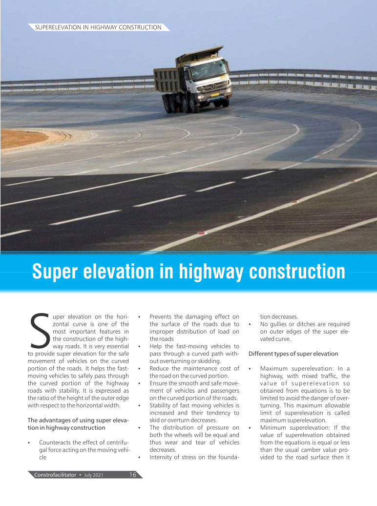
uper elevation on the hori-
Szontal curve is one of the most important features in the construction of the high-way roads. It is very essential
to provide super elevation for the safe movement of vehicles on the curved portion of the roads. It helps the fast-moving vehicles to safely pass through the curved portion of the highway roads with stability. It is expressed as the ratio of the height of the outer edge with respect to the horizontal width.
The advantages of using super eleva-tion in highway construction
Ÿ Counteracts the effect of centrifu-gal force acting on the moving vehi-cle
Ÿ Prevents the damaging effect on the surface of the roads due to improper distribution of load on the roads
Ÿ Help the fast-moving vehicles to pass through a curved path with-out overturning or skidding.
Ÿ Reduce the maintenance cost of the road on the curved portion.
Ÿ Ensure the smooth and safe move-ment of vehicles and passengers on the curved portion of the roads.
Ÿ Stability of fast moving vehicles is increased and their tendency to skid or overturn decreases.
Ÿ The distribution of pressure on both the wheels will be equal and thus wear and tear of vehicles decreases.
Ÿ Intensity of stress on the founda-
tion decreases.Ÿ No gullies or ditches are required
on outer edges of the super ele-vated curve.
Different types of super elevation
Ÿ Maximum superelevation: In a highway, with mixed traffic, the va lue of supere levat ion so obtained from equations is to be limited to avoid the danger of over-turning. This maximum allowable limit of superelevation is called maximum superelevation.
Ÿ Minimum superelevation: If the value of superelevation obtained from the equations is equal or less than the usual camber value pro-vided to the road surface then it
SUPERELEVATION IN HIGHWAY CONSTRUCTION
Super elevation in highway construction
Constrofacilitator • July 2021 16

should be equal to the camber slope.
Methods of superelevation
To change the cambered section of the road into a super elevated one, two steps are taken.
Ÿ Firstly, the camber on the outer edge is eliminated gradually till the road pavement has one straight tilt or slope from the inner to the outer edge (El imination of crown method).
Ÿ Secondly, this straight line slope gradually increases till the desired super elevation is attained. (Rotat-ing pavement method).
Outer slope rotation method
In the first method, the outer slope of the road is slowly rotated around the crown by progressively decreasing its inclination or gradually raising the outer edge. This inclination of the outer slope tangential to the crown surface firstly reaches horizontal. Then it slowly increases till it has attained the same inward slope. The main disadvantage
Constrofacilitator • July 202117
SUPERELEVATION IN HIGHWAY CONSTRUCTION
of this method is the difficulty of drain-ing water in some portion of the road length where the slope on the outer edge is less (gradually decreased) than the camber provided on the road. This method is commonly used on Indian highways.
Diagonal crown method
In the diagonal crown method, the cam-bered section of the road is eliminated by progressively shifting the crown towards the outer edge along the extension of the inner slope.
Conclusion
Different advantages and methods to achieve superelevation is discussed above depending upon the topography and design analysis that need to be cre-ated.

Expressway projects construction being monitored by road ministry, NHAI, says Union Minister Nitin Gadkari
The work progress of expressway projects is being moni-tored by the road ministry and the National Highways Authority of India at top level, Parliament was informed on Thursday.
In response to a question in the Lok Sabha, Road trans-port minister Nitin Gadkari said that regional offices of NHAI and project implementation units are also moni-toring these projects to ensure timely completion.
All expressway projects are targeted for completion by 2024-25, the minister said.
As per the minister's written reply, Delhi-Mumbai Ex-pressway (1,291 km), Delhi-Amritsar-Katra Express-way (672 km), Bengaluru-Chennai Expressway (262 km), Ahmedabad-Dholera Expressway (109 km), Kanpur-Lucknow Expressway (63 km), Dwarka Ex-pressway (28 km) and Delhi-Meerut Expressway (82 km) are targeted for completion by the year 2024-25.
"The implementation and timely completion of projects are monitored by Ministry and National Highways Au-thority of India at headquarters level as well as regional offices and project implementation units level through periodic review meetings," Gadkari said.
He informed that as of now, three foreign agencies--Dhaya Maju Infrastructure (Asia) Sdn. Berhad (DMI), JiangXi Construction Engineering (Group) Corporation Limited & OJSC Euro-Asian Construction Corporation Evrascon--are involved in the construction of Delhi-Mumbai Expressway and Delhi-Amritsar-Katra Ex-pressway through joint ventures with Indian infrastruc-
18 July 2021 • Constrofacilitator
ture companies.
Replying to a separate question with regard to vehicle scrappage policy, Gadkari said the ministry does not have any data on the amount being given by scrap com-panies in lieu of old two-wheelers and four-wheelers and other vehicles under the new vehicle scrappage pol-icy.
"Government has issued notification no. GSR 190(E) dated 15.03.2021 which provides for Motor Vehicles (Registration and Functions of Vehicle Scrapping Facil-ity) Rules, 2021 for establishment of Registered Vehi-cles Scrapping Facility (RVSF).
"The transactions between RVSF and vehicle owners are market based and not determined by the govern-ment," Gadkari said.
In his reply to another question, he said the ministry has identified 5,803 black spots on national highways based on accident and fatality data of year 2015-2018 in 30 states/UTs.
"Out of 5,803 black spots, temporary measures have been taken on 5,167 black spots and 2,923 black spots have been permanently rectified," Gadkari said.
The minister also informed that so far 703 km length of national highways have been constructed using waste plastic in wearing coat of flexible pavement.
NEWS
Nitin Gadkari, Ministry of Road Transport and Highways of India
Source: freepressjournal.in

Widening of final leg of Tiruchi-Chidambaram NH to begin soon
The National Highways Authority of India (NHAI) is all set to commence work on the third package of Tiruchi-Chidambaram National Highway widening project, cov-ering the final leg between Meensuritti and Chidambaram, shortly.
The 134-km long Tiruchi-Chidambaram National High-way is being widened at a total investment of about ₹4,000 crore. The NHAI is executing the project in three packages -- while package-I covers the Tiruchi-Kallagam stretch, package-II runs from Kallagam to Meensuritti and package-III will cover the stretch be-tween Meensuritti in Ariyalur district and Chidambaram in Cuddalore district.
Work on the first two packages is already under way and has made substantial progress. The NHAI had earlier called for fresh bids for the third package after the initial contract was terminated due to land acquisition issues. The contract has since been awarded and the work is set to begin shortly, NHAI sources said. “The contractor is on the ground and the work will begin in the first or sec-ond week of August. Land acquisition for widening the stretch has been completed,” the sources told The Hindu.
According to sources, nearly 75% of the work on the first package has been completed so far and 55-65% of the works have been completed on the second package. Work on both the stretches is expected to be completed by January 2022.
Package III will cover 31 km of the highway stretch, of which about 26 km will be bypass road stretches, mak-ing it almost a greenfield highway. The third and final package is set to be completed within two years from the date of commencement of works.
The first 50 km of the highway, from Tiruchi to nearly Keezha Pazhur, is being converted into a four-lane high-way with carriage ways of 8.7 metres on each side. Be-yond this point, it will be a two-lane highway with paved shoulders. The two-lane highway would have a width of
19July 2021 • Constrofacilitator
10 metres.
The project is expected to come as a boon to residents of Tiruchi, Ariyalur and Cuddalore and the industries lo-cated along the highway. A massive flyover is being con-structed near Samayapuram providing a link between the Tiruchi-Chennai and Tiruchi-Chidambaram Na-tional Highways. Bypass roads will come up at various places including Lalgudi-Poovalur, Keezha Pazhur, Mela Pazhur, Jayamkondam and Kattumannarkovil.
The Tiruchi-Kallagam section is a busy stretch of the highway with high traffic volume of goods vehicles as several cement factories are located along the highway. Road accidents involving vehicles carrying raw materi-als to the cement units often leads to protests in and around Ariyalur, triggering demands for construction of underpasses at various places.
Though the non availability of migrant labourers had im-pacted the work during the lockdown last year, the NHAI had subsequently resumed work on the first two packages of the project after obtaining permission from the authorities in the districts.
NEWS
Source: thehindu.com
A new flyover has been built to link Tiruchi-Chennai and Tiruchi - Chidambaram highways near Samayapuram in Tiruchi
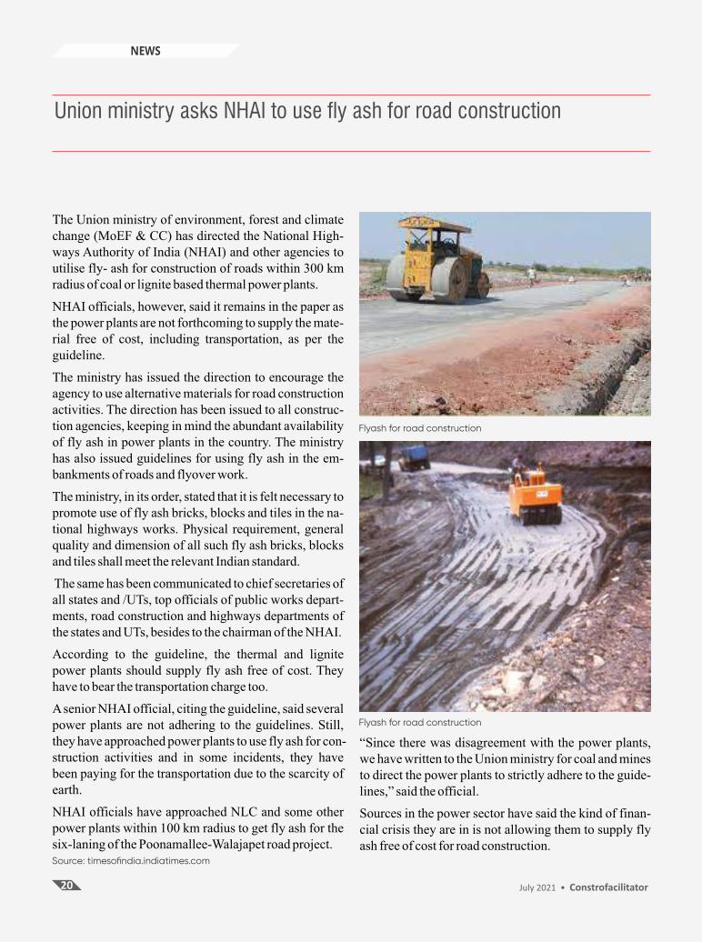
Union ministry asks NHAI to use fly ash for road construction
The Union ministry of environment, forest and climate change (MoEF & CC) has directed the National High-ways Authority of India (NHAI) and other agencies to utilise fly- ash for construction of roads within 300 km radius of coal or lignite based thermal power plants.
NHAI officials, however, said it remains in the paper as the power plants are not forthcoming to supply the mate-rial free of cost, including transportation, as per the guideline.
The ministry has issued the direction to encourage the agency to use alternative materials for road construction activities. The direction has been issued to all construc-tion agencies, keeping in mind the abundant availability of fly ash in power plants in the country. The ministry has also issued guidelines for using fly ash in the em-bankments of roads and flyover work.
The ministry, in its order, stated that it is felt necessary to promote use of fly ash bricks, blocks and tiles in the na-tional highways works. Physical requirement, general quality and dimension of all such fly ash bricks, blocks and tiles shall meet the relevant Indian standard.
The same has been communicated to chief secretaries of all states and /UTs, top officials of public works depart-ments, road construction and highways departments of the states and UTs, besides to the chairman of the NHAI.
According to the guideline, the thermal and lignite power plants should supply fly ash free of cost. They have to bear the transportation charge too.
A senior NHAI official, citing the guideline, said several power plants are not adhering to the guidelines. Still, they have approached power plants to use fly ash for con-struction activities and in some incidents, they have been paying for the transportation due to the scarcity of earth.
NHAI officials have approached NLC and some other power plants within 100 km radius to get fly ash for the six-laning of the Poonamallee-Walajapet road project.
20 July 2021 • Constrofacilitator
“Since there was disagreement with the power plants, we have written to the Union ministry for coal and mines to direct the power plants to strictly adhere to the guide-lines,” said the official.
Sources in the power sector have said the kind of finan-cial crisis they are in is not allowing them to supply fly ash free of cost for road construction.
NEWS
Flyash for road construction
Flyash for road construction
Source: timesofindia.indiatimes.com

eMagazine is a digital medium for interac�on among the various personnel among the construc�on industry namely, Manufacturers, Business to
Business users and the Civil Engineering professionals.
What is the huss about eMagazine

B2B and knowledge portal for Architecture, Civil and
Infrastructure industry
Follow us on