Figure II-2.2: Typical Steel Reinforced Elastomeric Bearing ...
Upload
independentCategory
view
2download
0
Ion beam figuring of high-slope surfaces basedon figure error compensation algorithm
Yifan Dai, Wenlin Liao,* Lin Zhou, Shanyong Chen, and Xuhui XieNational University of Defense Technology, DeYa Road, Changsha, Hunan, China 410073
*Corresponding author: [email protected]
Received 19 August 2010; revised 6 October 2010; accepted 15 October 2010;posted 18 October 2010 (Doc. ID 133673); published 30 November 2010
In a deterministic figuring process, it is critical to guarantee high stability of the removal function as wellas the accuracy of the dwell time solution, which directly influence the convergence of the figuring pro-cess. Hence, when figuring steep optics, the ion beam is required to keep a perpendicular incidence, and afive-axis figuring machine is typically utilized. In this paper, however, a method for high-precision figur-ing of high-slope optics is proposed with a linear three-axis machine, allowing for inclined beam inci-dence. First, the changing rule of the removal function and the normal removal rate with theincidence angle is analyzed according to the removal characteristics of ion beam figuring (IBF). Then,we propose to reduce the influence of varying removal function and projection distortion on the dwell timesolution by means of figure error compensation. Consequently, the incident ion beam is allowed to keepparallel to the optical axis. Simulations and experiments are given to verify the removal analysis. Finally,a figuring experiment is conducted on a linear three-axis IBF machine, which proves the validity of themethod for high-slope surfaces. It takes two iterations and about 9min to successfully figure a fused silicasample, whose aperture is 21.3 mm and radius of curvature is 16 mm. The root-mean-square figure errorof the convex surface is reduced from 13.13 to 5.86 nm. © 2010 Optical Society of AmericaOCIS codes: 220.4610, 220.5450.
1. Introduction
Ion beam figuring (IBF) possesses the advantage ofnanometer precision with material removed by thephysical sputtering effect, where energy is trans-ferred from the energetic ions to the optical surfaceduring the bombarding process [1–3]. IBF is highlydeterministic, highly stable, and noncontact, whichmakes it advantageous over conventional figuringtechnology. Problems that exist in conventional figur-ing processes, such as the edge effect, tool wear, andpressure load, disappear naturally. All these advan-tages distinguish IBF as the final procedure forhigh-precision optics manufacture [2,3].
IBF is also based on the computer-controlled opti-cal surfacing (CCOS) technology, first proposed byItek Inc. in the 1970s, where a small polishing toolis employed and controlled by a computer to figure
optical surfaces [4,5]. The surface figure errorE0ðx; yÞ before processing is first measured, e.g., withan interferometer. Then, the removal function Rðx; yÞunder constant process parameters is obtainedthrough experiments. Since the material Eðx; yÞ to beremoved is a two-dimensional (2-D) convolution ofthe removal function and the dwell time Tðx; yÞ, a de-convolution operation is involved to calculate thedwell time [1]. Typically after several iterations of er-ror figuring and measurement, the sum of removedmaterial Eiðx; yÞ in each iteration is expected to ap-proach the ideally removed material E0ðx; yÞ as nearas possible.
The above method is applicable to planes and flatslope optics without additional processing. However,the problem of projection distortion must be consid-ered seriously in processing high-slope surfaceswhen the surface error Eðx; y; zÞ is projected from athree-dimensional (3-D) Cartesian frame to a 2-Dframe, resulting in Eðx; yÞ for the deconvolution op-eration. Furthermore, in order to maintain a
0003-6935/10/346630-07$15.00/0© 2010 Optical Society of America
6630 APPLIED OPTICS / Vol. 49, No. 34 / 1 December 2010
constant removal function at every dwell point, theion beam is usually held perpendicular to the sur-faces. This means at least five axes and a larger workspace are required. If we can figure high-slope sur-faces with a linear three-axis machine, it is definitelyeconomical and more reliable compared with a five-axis system. Related research on figuring of stronglycurved surfaces with a linear three-axis system wasreported by the Leibniz Institute of Surface Modifi-cation in Leipzig, Germany, with good results [6].However, much preliminary work must be done toget the required information of removal rates andbeam shape in dependence of the incidence anglewhen figuring optics of different materials andshapes. In addition, the calculation model of dwelltime is complex and different from that for flat sur-faces, which debases the program universality.
In this paper, the changing rule of the removalfunction with the incidence angle is analyzed underconstant process parameters, based on theoreticaland experimental investigation of the removal char-acteristics. By means of surface figure error compen-sation, the influences of varying removal functionand projection distortion on the dwell time solutionare diminished. The program for flat surfaces canalso be applied to high-slope surfaces for dwell timecalculation. This method is finally approved by an ex-periment of figuring high-slope convex surface.
2. Algorithm for Dwell Time Calculation
According to the CCOS principle, the removed mate-rial Eðx; yÞ is a convolution of the removal functionRðx; yÞ and the dwell time Tðx; yÞ, given as follows:
Eðx; yÞ ¼ Rðx; yÞ � Tðx; yÞ
¼Z
∞
−∞
Z∞
−∞
Rðx − x0; y − y0ÞTðx0; y0Þdx0dy0: ð1Þ
It can be rewritten in the discretized form
Eðx; yÞ ¼Xi¼0
Xj¼0
Rðx − x0i; y − y0jÞTðx0i; y0jÞΔx0Δy0 þ ξ;
ð2Þ
where ξ is the statistical error, which is a summar-ized value composed of the error of themeasurement,the change of the removal function and the speed,and the position error of the motion system.
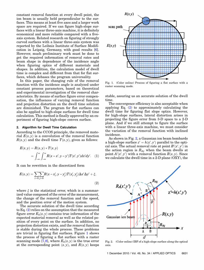
The accurate solution of the dwell time accordingto Eq. (2) relies on the assumption that the measuredfigure error E0ðx; yÞ contains true information of theexpected material removal as well as the related po-sition of every point on the surface. In addition, noprojection distortion exists, and the removal functionis stable during the whole process. These problemsare trivial in figuring flat surfaces. Figure 1 showsthe process of figuring a flat surface with a rasterscanning mode [7,8], where E0ðx; yÞ is the true errorat the corresponding point ðx; yÞ, and Rðx; yÞ keeps
stable, assuring us an accurate solution of the dwelltime.
The convergence efficiency is also acceptable whenapplying Eq. (2) to approximately calculating thedwell time for figuring flat slope optics. However,for high-slope surfaces, lateral distortion arises inprojecting the figure error from 3-D space to a 2-Dplane. And if we still attempt to figure the surfacewith a linear three-axis machine, we must considerthe variation of the removal function with inclinedincidence.
As shown in Fig. 2, a Gaussian ion beam bombardsa high-slope surface z0 ¼ hðx0; y0Þ parallel to the opti-cal axis. The actual removal rate at point B0ðx0; y0Þ inthe action region is Rθij when the beam dwells atpoint A0ðx0; y0Þ with a removal function Rðx; yÞ. Sincewe calculate the dwell time in a 2-D plane (OXY), the
Fig. 1. (Color online) Process of figuring a flat surface with araster scanning mode.
Fig. 2. (Color online) IBF of a high-slope surface along the opticalaxis.
1 December 2010 / Vol. 49, No. 34 / APPLIED OPTICS 6631
nominal removal rate at Bðx; yÞ is Rij, which is ob-viously unequal to the actual one Rθij. The normal-ized removal rate is introduced as below:
Kij ¼RθijRij
; ð3Þ
where θ is the incidence angle. Rθij and Rij aredefined as follows:
Rθij ¼ Rθðx0 − x0i; y0 − y0jÞ; Rij ¼ Rðx0 − x0i; y
0 − y0jÞ;
so the actual removal rate becomes Rθij ¼ KijRij.Substituting it into Eq. (2) yields the accuratematerial removal:
Eðx; yÞ ¼Xi¼0
Xj¼0
KijRðx − x0i; y − y0jÞTðx0j; y0jÞΔx0Δy0 þ ξ:
ð4Þ
It is complicated and unnecessary to directly solveEq. (4) for the dwell time. We prefer to simplify itwith the coefficient Kij eliminated according to theremoval characteristics in the IBF process. And thenthe original program developed for figuring flat sur-faces is still applicable to high-slope surfaces.
3. Removal Characteristics
A. Etching Rate of the Ion Beam
Great efforts were made by Sigmund in the ion sput-tering theory, including explanation of the sputteringmechanism and derivation of the sputtering yield for-mula [9], which lay a foundation for study of removalcharacteristics in the IBF process.
In 1988, based on Sigmund’s theory of sputtering,Bradley and Harper [10] deduced the etching rate ofa uniform ion beam with inclined incidence on an ar-bitrary surface z ¼ hðx; yÞ (shown in Fig. 3):
Rðθ; c1; c2Þ ¼ ðf =nÞY0ðθÞ½cos θ − Γ1ðθÞc1 − Γ2ðθÞc2�;ð5Þ
where Y0ðθÞ is the sputtering yield when the uniformion beam obliquely bombards a flat surface at an in-cidence angle θ, and Y0ðθÞ is given as follows:
Y0ðθÞ ¼pεnαffiffiffiffiffiffi2π
pσμ
exp�−
α22σ2
�B−1=2
1 ðθÞ exp�
A2ðθÞ2B1ðθÞ
�;
where f is the ion flux, n is the number of atoms perunit volume in the amorphous solid, θ is the inci-dence angle, ε is the total energy deposited, and pis a proportion factor relating the deposited powerto the rate of erosion. The other coefficients are de-fined as follows:
Γ1ðθÞ ¼AðθÞB1ðθÞ
sin θ − B2ðθÞ2B1ðθÞ
�1þ A2ðθÞ
B1ðθÞ�cos θ
−AðθÞCðθÞB2
1ðθÞ�3þ A2ðθÞ
B1ðθÞ�cos θ;
Γ2ðθÞ ¼ −μ2a2 cos θ
�12B2ðθÞ þ
AðθÞCðθÞB1ðθÞ
�;
AðθÞ ¼�aσ
�2sin θ;
B1ðθÞ ¼�aσ
�2sin2 θ þ
�aμ
�2cos2 θ;
B2ðθÞ ¼�aσ
�2cos θ;
CðθÞ ¼ 12
��aμ
�2−
�aσ
�2�sin θ cos θ;
where α is the average incidence depth of the ions,and σ and μ are the Gaussian parameters of the dis-tribution parallel and perpendicular to the beam di-rection, respectively.
For most surfaces, c1 and c2 can be given by
�c1 ¼ α=r0x ¼ α ∂2h
∂x2ð0Þ
c2 ¼ α=r0y ¼ α ∂2h∂y2
ð0Þ ;
where the value of α is in nanometers and not com-parable in magnitude with r0x and r0y. Hence, c1 andc2 are infinitesimals, while Γ1 and Γ2 are finite coef-ficients. As a result, Eq. (5) can be approximated by
RðθÞ ¼ ðf =nÞY0ðθÞ cos θ: ð6Þ
Although it is the etching rate of uniform ion flux inthe micro area, it is applicable to the ion beam withthe diameter at the millimeter scale, because the fluxat local points in the action zone can be consideredidentical. According to Eq. (6), when other processparameters are constant,RðθÞ is a function of a singlevariable θ, so Eq. (3) becomes
KijðθÞ ¼RijðθÞRij
: ð7Þ
Fig. 3. (Color online) Ion beam bombarding the surface at angle θ.
6632 APPLIED OPTICS / Vol. 49, No. 34 / 1 December 2010
When the ion beam figures the surface parallel to theoptical axis, the incidence angle θ is only related tothe position ðx; yÞ of the processing point, regardlessof the dwell point. Therefore, Eq. (4) can be modifiedas
Eðx; yÞ ¼ Kðx; yÞXi¼0
Xj¼0
Rðx − x0i; y − y0jÞTðx0i; y0jÞΔx0Δy0
þ ξ: ð8Þ
This equation is rewritten by dividing Kðx; yÞ at bothsides:
E0ðx; yÞ ¼Xi¼0
Xj¼0
Rðx − x0i; y − y0jÞTðx0i; y0jÞΔx0Δy0 þ ξ0;
ð9Þwhere E0ðx; yÞ ¼ Eðx; yÞ=Kðx; yÞ and ξ0 ¼ ξ=Kðx; yÞ.
From Eq. (9), we can diminish the influence of thevarying removal function with surface figure errorcompensation when figuring high-slope surfaceswith a linear three-axis system. And the dwell timecan be calculated by deconvolution using the sameprogram as for flat surfaces.
B. Theoretical Model of the Removal Function
When an ion beam with the flux f strikes the surfaceat pointO at the incidence angle θ, the distribution offlux is approximately f ðx cos θ; yÞ in the workpieceframe fx; y; zg, as shown in Fig. 3. Thereby, the the-oretical model of the removal function is given by
Rðx; yÞ ¼ ð1=nÞY0ðθÞ cos θf ðx cos θ; yÞ: ð10ÞSubstituting the normalized removal rate Kij intoEq. (10), once the removal function with perpendicu-lar incidence is obtained through experiments, thefunction at an arbitrary incidence angle can be repre-sented by
Rðx; yÞ ¼ KθR0f ðx cos θ; yÞ: ð11Þ
4. Removal Simulation and Experiments
A. Simulation of the Energy Dispersion
SRIM software [11] is utilized to simulate the energydispersion of 5000 Ar ions vertically bombarding theSiO2 target with the energy of 800 eV. The resultshows that the average incidence depth of ions isα ¼ 3:7nm, and the Gaussian distribution para-meters are σ ¼ 1:8nm and μ ¼ 1:3nm.
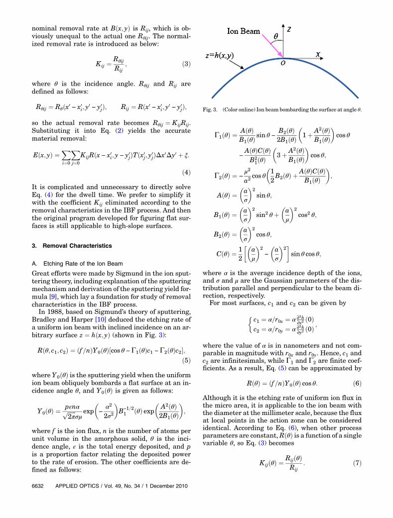
B. Normalized Peak Removal Rate
The curve of the normalized peak removal rate ac-cording to Eq. (11) is shown in Fig. 4 with the energydispersion parameters determined. It can be verifiedthrough experiments with the ion beam scanning lin-early and etching a fused silica sample along one ofits generatrix. The target distance is fixed, and theconstant scanning velocity is 1mm=min. The aper-ture of the target surface is 21:3mm, and the radiusof curvature is 16mm, which indicates that the max-imal incidence angle is 41:7°. The actual material re-moval is shown in Fig. 5. For the purpose of
Fig. 4. (Color online) Theoretical and experimental curves of theremoval rate.
Fig. 5. (Color online) Removal result by linearly scanning aspherical surface.
Fig. 6. (Color online) Material removed in the linear scanningexperiment.
1 December 2010 / Vol. 49, No. 34 / APPLIED OPTICS 6633
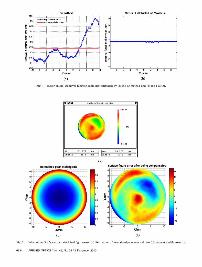
Fig. 7. (Color online) Removal function diameter estimated by (a) the 6σ method and (b) the FWHM.
Fig. 8. (Color online) Surface error: (a) original figure error, (b) distribution of normalized peak removal rate, (c) compensated figure error.
6634 APPLIED OPTICS / Vol. 49, No. 34 / 1 December 2010
comparison, we also draw the experimental curve ofthe removal rate in Fig. 4. It is consistent with thetheoretical curve. Therefore, it is reasonable to applythe theoretical model instead of a series of experi-ments to get the removal rate for high-slope samplesof various apertures and various curvatures, result-ing in much higher productivity.
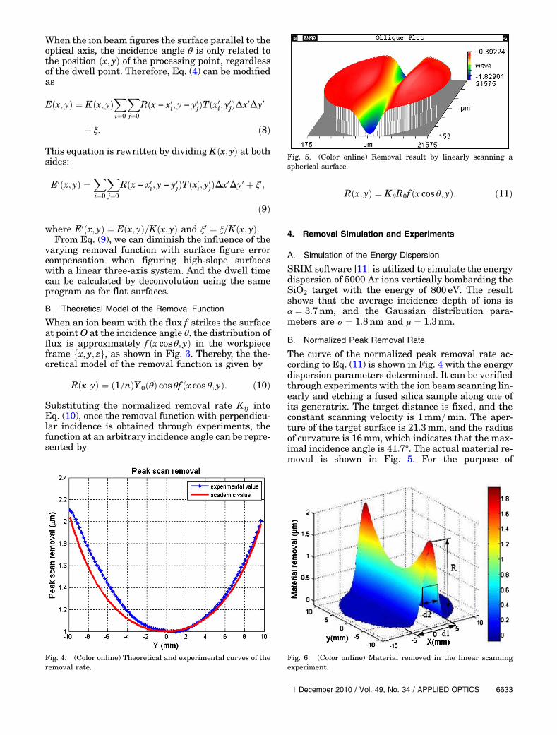
C. Diameter of the Removal Function
The material removed (shown in Fig. 6) is fitted to aGaussian distribution along the y-direction with theGauss–Newton method to get the diameters of re-moval function footprints along the x-direction at var-ious incidence angles. Figure 7 shows the curve of thediameter estimated bya statistical 6σmethodand fullwidth at half-maximum (FWHM), respectively.
The experimental result indicates that the dia-meter ranges from 8.1 to 8:7mm, and the fluctuationis less than 5.2% when estimated by the 6σ method,while the diameter estimated by the FWHM does notchange evidently. The diameter measured perpendi-cular to the scanning direction is constant, becausethe normal at each incidence point remains in theXOZ plane throughout the scanning process, andthe incidence angle only has an effect on the dia-meter along the y direction. This experimental resultis consistent with the theoretical model of Eq. (9).
5. Figuring Results and Discussions
The spherical convex surface of a fused silica sampleis usedwith the sameparameters as inSubsection4.B(aperture 21:3mm and radius of curvature 16mm).Allowing for the large incidence angle and the smallaperture, it is a high-slope surface. The ion beamwitha diameter of 5:7mm (6σ) is adopted on a linear three-axis figuring machine. And the figuring process is thesame as for flat surfaces. Readers are referred to Ref.[12] for details.
Figure 8(a) shows the original surface error mapbefore figuring [101:9nm peak-to-valley (PV) and13:1nm root mean square (RMS)]. The distributionof the normalized removal rate Kij, according to
the theoretical analysis and experimental study, isgiven in Fig. 8(b), and the compensated surface errorE0ðx; yÞ in Eq. (9) is shown in Fig. 8(c).
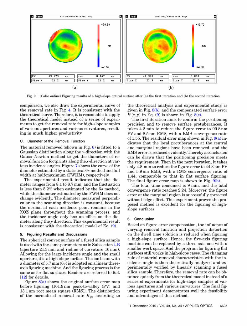
The first iteration aims to confirm the positioningprecision and to remove surface protuberances. Ittakes 4:2 min to reduce the figure error to 99:8nmPV and 8:5nm RMS, with a RMS convergence ratioof 1.55. The residual error map shown in Fig. 9(a) in-dicates that the local protuberances at the centraland marginal regions have been removed, and theRMS error is reduced evidently. Thereby a conclusioncan be drawn that the positioning precision meetsthe requirement. Then in the next iteration, it takesonly 4:8 min to reduce the figure error to 44:3nm PVand 5:9nm RMS, with a RMS convergence ratio of1.44, comparable to that in flat surface figuring.The final figure error map is shown in Fig. 9(b).
The total time consumed is 9 min, and the totalconvergence ratio reaches 2.24. Moreover, the figureerror at the marginal region is successfully correctedwithout edge effect. This experiment proves the pro-posed method is excellent for the figuring of high-slope surfaces.
6. Conclusion
Based on figure error compensation, the influence ofvarying removal function and projection distortionon the dwell time solution is reduced when figuringa high-slope surface. Hence, the five-axis figuringmachine can be replaced by a three-axis one with asmaller work space. And the program for figuring flatsurfaces still works in high-slope cases. The changingrule of material removal characteristics with the in-cidence angle is then theoretically analyzed and ex-perimentally verified by linearly scanning a fusedsilica sample. Therefore, the removal rate can be ob-tained quickly from the theoretical model instead of aseries of experiments for high-slope samples of var-ious apertures and various curvatures. The final fig-uring experiment demonstrates well the feasibilityand advantages of this method.
Fig. 9. (Color online) Figuring results of a high-slope optical surface after (a) the first iteration and (b) the second iteration.
1 December 2010 / Vol. 49, No. 34 / APPLIED OPTICS 6635
The limitation is that the maximal incidence angleis required to within about 60°. For higher-slope sur-faces, the uniform gridding partition of surface errorin a 2-D plane would lead to a loss of local details, in-cluding some high-frequency errors. We hope toaddress this problem in future work with a smallerIBF tool and figuring with the subregion stitchingmethod.
References1. T. W. Drueding, T. G. Bifano, and S. C. Fawcett, “Contouring
algorithm for ion figuring,” Precis. Eng. 17, 10–21 (1995).2. L. N. Allen and H. W. Romig, “Demonstration of an ion figur-
ing process,” Proc. SPIE 1333, 22–23 (1990).3. L. N. Allen, “Progress in ion figuring large optics,” Proc. SPIE
2428, 237–247 (1995).4. L.Zhou,Y.Dai,X.Xie,C.Jiao,andS.Li,“Machiningreachability
in ion beam figuring,” Opt. Precis. Eng. 15, 160–166 (2001).5. C. Jiao, S. Li, X. Xie, L. Zhou, andW.Duan, “Bayesian principle
baseddwell timealgorithmfor ionbeamfiguringof lowgradientmirrors,” J. Mech. Eng. Lab. 45, 253–259 (2009).
6. T. Haensel, A. Nickel, and A. Schindler, “Ion beam figuringof strongly curved surfaces with a ðx; y; zÞ linear three-axes system,” in Plasmonics and Metamaterials, OSA Techni-cal Digest (CD) (Optical Society of America, 2008), paperJWD6.
7. R. A. Jones and W. J. Rupp, “Rapid optical fabrication withCCOS,” Proc. SPIE 1333, 34–43 (1990).
8. A. Schindler, T. Hänsel, F. Frost, R. Fechner, A. Nickel,H. Thomas, H. Neumann, and D. Hirsch, “Ion beamfinishing technology for high precision optics production,”in Optical Fabrication and Testing, Vol. 76 of OSA Trendsin Optics and Photonics, A. Sawchuk, ed. (2002), paperOTuB5.
9. P. Sigmund, “Amechanism of surface micro-roughening by ionbombardment,” J. Mater. Sci. Technol. (Sofia) 8, 1545–1553(1973).
10. R. M. Bradley and J. M. E. Harper, “Theory of ripple topogra-phy induced by ion bombardment,” J. Vac. Sci. Technol. A 6,2390–2395 (1988).
11. “Particle Interactions with Matter,” http://www.srim.org.12. L. Zhou, “Study on theory and technology in ion beam figuring
for optical surfaces,” Ph.D. dissertation (National Universityof Defense Technology, 2008), in Chinese.
6636 APPLIED OPTICS / Vol. 49, No. 34 / 1 December 2010
Copyright © 2022 FDOKUMEN