Investigation on Log-Periodic Dielectric Resonator Antenna Array for Ku-Band Applications
17
This article was downloaded by: [National Institute of Technology - Rourkela] On: 16 February 2015, At: 04:48 Publisher: Taylor & Francis Informa Ltd Registered in England and Wales Registered Number: 1072954 Registered office: Mortimer House, 37-41 Mortimer Street, London W1T 3JH, UK Click for updates Electromagnetics Publication details, including instructions for authors and subscription information: http://www.tandfonline.com/loi/uemg20 Investigation on Log-Periodic Dielectric Resonator Antenna Array for Ku-Band Applications Runa Kumari a & Santanu Kumar Behera a a Department of Electronics and Communication Engineering , National Institute of Technology , Rourkela , Odisha , India Published online: 10 Dec 2013. To cite this article: Runa Kumari & Santanu Kumar Behera (2014) Investigation on Log-Periodic Dielectric Resonator Antenna Array for Ku-Band Applications, Electromagnetics, 34:1, 19-33, DOI: 10.1080/02726343.2014.846175 To link to this article: http://dx.doi.org/10.1080/02726343.2014.846175 PLEASE SCROLL DOWN FOR ARTICLE Taylor & Francis makes every effort to ensure the accuracy of all the information (the “Content”) contained in the publications on our platform. However, Taylor & Francis, our agents, and our licensors make no representations or warranties whatsoever as to the accuracy, completeness, or suitability for any purpose of the Content. Any opinions and views expressed in this publication are the opinions and views of the authors, and are not the views of or endorsed by Taylor & Francis. The accuracy of the Content should not be relied upon and should be independently verified with primary sources of information. Taylor and Francis shall not be liable for any losses, actions, claims, proceedings, demands, costs, expenses, damages, and other liabilities whatsoever or howsoever caused arising directly or indirectly in connection with, in relation to or arising out of the use of the Content. This article may be used for research, teaching, and private study purposes. Any substantial or systematic reproduction, redistribution, reselling, loan, sub-licensing, systematic supply, or distribution in any form to anyone is expressly forbidden. Terms &
-
Upload
independent -
Category
Documents
-
view
5 -
download
0
Transcript of Investigation on Log-Periodic Dielectric Resonator Antenna Array for Ku-Band Applications

This article was downloaded by: [National Institute of Technology - Rourkela]On: 16 February 2015, At: 04:48Publisher: Taylor & FrancisInforma Ltd Registered in England and Wales Registered Number: 1072954 Registeredoffice: Mortimer House, 37-41 Mortimer Street, London W1T 3JH, UK
Click for updates
ElectromagneticsPublication details, including instructions for authors andsubscription information:http://www.tandfonline.com/loi/uemg20
Investigation on Log-Periodic DielectricResonator Antenna Array for Ku-BandApplicationsRuna Kumari a & Santanu Kumar Behera aa Department of Electronics and Communication Engineering ,National Institute of Technology , Rourkela , Odisha , IndiaPublished online: 10 Dec 2013.
To cite this article: Runa Kumari & Santanu Kumar Behera (2014) Investigation on Log-PeriodicDielectric Resonator Antenna Array for Ku-Band Applications, Electromagnetics, 34:1, 19-33, DOI:10.1080/02726343.2014.846175
To link to this article: http://dx.doi.org/10.1080/02726343.2014.846175
PLEASE SCROLL DOWN FOR ARTICLE
Taylor & Francis makes every effort to ensure the accuracy of all the information (the“Content”) contained in the publications on our platform. However, Taylor & Francis,our agents, and our licensors make no representations or warranties whatsoever as tothe accuracy, completeness, or suitability for any purpose of the Content. Any opinionsand views expressed in this publication are the opinions and views of the authors,and are not the views of or endorsed by Taylor & Francis. The accuracy of the Contentshould not be relied upon and should be independently verified with primary sourcesof information. Taylor and Francis shall not be liable for any losses, actions, claims,proceedings, demands, costs, expenses, damages, and other liabilities whatsoever orhowsoever caused arising directly or indirectly in connection with, in relation to or arisingout of the use of the Content.
This article may be used for research, teaching, and private study purposes. Anysubstantial or systematic reproduction, redistribution, reselling, loan, sub-licensing,systematic supply, or distribution in any form to anyone is expressly forbidden. Terms &

Conditions of access and use can be found at http://www.tandfonline.com/page/terms-and-conditions
Dow
nloa
ded
by [
Nat
iona
l Ins
titut
e of
Tec
hnol
ogy
- R
ourk
ela]
at 0
4:48
16
Febr
uary
201
5
Electromagnetics, 34:19–33, 2014
Copyright © Taylor & Francis Group, LLC
ISSN: 0272-6343 print/1532-527X online
DOI: 10.1080/02726343.2014.846175
Investigation on Log-Periodic Dielectric Resonator
Antenna Array for Ku-Band Applications
RUNA KUMARI1
and SANTANU KUMAR BEHERA1
1Department of Electronics and Communication Engineering, National Institute
of Technology, Rourkela, Odisha, India
Abstract A log-periodic dielectric resonator antenna array for Ku-band (12 to
18 GHz) applications is investigated. The resonators of a seven-element rectangular-
shaped dielectric resonator antenna array are arranged in a log-periodic fashion.The proposed antenna is excited by a log-periodic microstrip series feed line. It
provides broadband with 46% of wider impedance bandwidth covering a frequencyrange of 11.4 to 18 GHz with |S11| less than �10 dB. The proposed array achieved
a maximum gain of 11.4 dBi at a frequency of 14.5 GHz. The measured S-parameter,gain, and radiation patterns are presented for different frequencies. The scaling factor
of 1.05 has been chosen for this design. Simulated results are compared favorablywith physically measured values.
Keywords dielectric resonator antenna, Ku-band, log-periodic technique, microstripline feeding
1. Introduction
With incoming demands in multimedia communication, the needs for flexible com-
munication systems with high data rates are rising. Satellite communication systems
provide flexibility as well as high-speed data transfer at high frequencies. For digital data
transmission via satellites, the Ku-band is preferred. The Ku-band offers a user more
flexibility as it is less vulnerable to rain fading than other frequency bands.
For satellite communication in the Ku-band (12 to 18 GHz), there is an inherent trade-
off between conductor losses and multi-frequency broad bandwidth. Recently, dielectri-
cally loaded antennas received extensive attention in wireless and satellite communication
due to their small dimensions, light weight, low profile, low dissipation loss, controllable
properties, high dielectric strength, higher power handling capacity, and perfect protection
from damages (Petosa, 2007; Luk & Leung, 2002).
Lower conductor losses can be expected in dielectric resonator antennas (DRAs)
compared to those in typical metal antennas, such as microstrip patches. DRAs can
be designed with different shapes to accommodate various design requirements. The
Received 15 February 2013; accepted 21 July 2013.Address correspondence to Ms. Runa Kumari, Department of Electronics and Communi-
cation Engineering, National Institute of Technology, Rourkela, Odisha, 769008, India. E-mail:[email protected]
Color versions ofone or more of the figures in the article can be found online at www.tandfonline.com/uemg.
19
Dow
nloa
ded
by [
Nat
iona
l Ins
titut
e of
Tec
hnol
ogy
- R
ourk
ela]
at 0
4:48
16
Febr
uary
201
5

20 R. Kumari and S. K. Behera
available basic shapes of dielectric resonators (DRs) are cylindrical, rectangular, and
hemispherical, whereas different modified shapes are also possible, which include ring,
disc, sectored cylindrical, half-split cylindrical, triangular, notched rectangular, conical,
and elliptical. DRAs can be excited with different feeding methods, such as probes, mi-
crostrip lines, slots, coplanar lines, and dielectric image guide feed. Bandwidth enhance-
ment is becoming the major design consideration for most practical DRA applications.
Several bandwidth enhancement techniques have been reported on changing the shape of
the DRAs, modified feed geometries, optimizing the feeding mechanism, stacked DRA,
embedded DRA, and DRA array (Petosa, 2007; Luk & Leung, 2002).
DRAs possess some unique properties that render them very promising, especially
for microwave and millimeter-wave applications. As compared to the microstrip antenna,
the DRA provides much wider impedance bandwidth (Mongia & Bhartia, 1994). The
gain, bandwidth, and radiation performance of DRAs can further be modified by using
an array instead of single DRA (Guha & Antar, 2006; Drossos et al., 1998).
Varieties of array designs have been proposed in literature to obtain broadband multi-
frequency operations; the electromagnetic bandgap (EBG) antenna using double-layer
frequency selective surfaces (Moustafa & Jecko, 2010), printed circuit board waveguide
(PCB-WG) fed array antennas (Borji et al., 2009), or coplanar waveguide spiral antennas
(Ghassemi et al., 2011) are those mostly exploited for Ku-band applications. In addition,
there are log-periodic arrays of special geometry (Wu et al., 2010; Chen et al., 2006;
Zhai et al., 2010) to achieve multi-frequency wideband applications.
The log-periodic technique is generally adopted to achieve bandwidth enhancement
and good radiation characteristics. It is a very sophisticated and an effective approach to
achieve multi-frequency broadband antenna design, which has evolved from the initial
work by a number of researchers at the University of Illinois. The class of antennas
that has resulted is called a frequency-independent or log-periodic antenna, which was
invented by Isbell (1960). These antennas achieve bandwidths of 10:1 with ease, and
much larger values are possible with careful design (Yang & Per-Simon, 2011). The log-
periodic planar array substantially extends the useful application area of such antennas
(Hall, 1980). It provides wide bandwidth systems with a versatile, low profile, light-
weight antenna with conformal mounting capabilities.
The design of a log-periodic antenna consists of a basic geometric pattern that repeats,
except with a different size of pattern, which results in repetitive behavior in its electrical
characteristics (Pues et al., 1981; Pantoja et al., 1987). In this antenna, it is normal to
drive an alternating element with 180ı phase shift from one another. The length, width,
and spacing of the elements of a log-periodic antenna increases logarithmically from
one end to the other. However, these metallic antennas suffer from conductor losses that
result in reduction in bandwidth and less radiation efficiency.
This article proposes a wideband log-periodic DRA (LPDRA) array that relies on
recent developments of wideband DRAs and the multi-frequency log-periodic technique.
As the log-periodic antenna provides multi-band, high-frequency wide bandwidth with
high gain and good radiation characteristics, to improve the bandwidth as well as the
radiation characteristics of the array, a log-periodic technique has been implemented on a
DRA. The LPDRA is introduced to achieve significant multi-frequency wide bandwidth
with low conductor loss for Ku-band applications. This antenna design has also included
a low-cost dielectric material (Teflon) with permittivity ("r ) of 2.1 for easy fabrication of
array. The design methodology of the DRA using the log-periodic technique is discussed,
and the detail results of the proposed antenna are investigated in this article. Finally, the
LPDRA offers continuous operation from 11.4- to 18-GHz bandwidth.
Dow
nloa
ded
by [
Nat
iona
l Ins
titut
e of
Tec
hnol
ogy
- R
ourk
ela]
at 0
4:48
16
Febr
uary
201
5

Investigation on LPDRA for Ku-Band 21
2. Antenna Configuration
Figure 1 shows the geometry of the LPDRA configuration, where rectangular-shaped
resonators of seven different sizes are arranged in log-periodic fashion.
The DR with a rectangular cross-section offers a second degree of freedom, making
it the most versatile and flexible among all basic-shaped DRAs. The length (L), width
(W ), height (H ), and spacing (S ) of the LPDRA elements increase logarithmically from
one end to other.
The schematic view of the LPDRA is shown in Figure 1(b). As microstrip line
feeding offers the advantage of easy and cost-effective fabrication of the DRA, so the
proposed LPDRA is excited by a 50-� microstrip line feeding. In the resonant approach,
the microstrip line is terminated in an open circuit, which creates a standing wave on
(a)
(b)
Figure 1. Proposed LPDRA: (a) top view, (b) schematic view, (c) front view of fabricated LPDRA,
and (d) rear view of fabricated LPDRA. (continued)
Dow
nloa
ded
by [
Nat
iona
l Ins
titut
e of
Tec
hnol
ogy
- R
ourk
ela]
at 0
4:48
16
Febr
uary
201
5

22 R. Kumari and S. K. Behera
(c)
(d)
Figure 1. (Continued).
Dow
nloa
ded
by [
Nat
iona
l Ins
titut
e of
Tec
hnol
ogy
- R
ourk
ela]
at 0
4:48
16
Febr
uary
201
5

Investigation on LPDRA for Ku-Band 23
the line where the voltage maxima/minima of each wave are located at multiples of
�g=2 from the open-circuit location. The guided wavelength �g can be approximated
using Eq. (1), where "r is the dielectric constant of the DR and �0 is the free-space
wavelength:
�g D �0p"r
: (1)
This design used DRs having a dielectric constant ("r ) D 2.1 (Teflon). The DRs
along with the feed line are mounted on the top side of an inexpensive FR4 substrate
measuring �250 mm long by 130 mm wide with a thickness (hs) of 1.6 mm, having
relative permittivity ("1) of 4.4 and a loss tangent (tan ı) of 0.001, as shown in Figure 1(b).
A partially printed ground plane with dimensions 195 mm � 130 mm (Lg � Wg) is
presented on the bottom side of the substrate to enhance the ensued bandwidth with the
full ground plane.
The basic design of the LPDRA is similar to that of a normal log-periodic array.
The proposed LPDRA consists of seven DRs of different lengths, widths, and spacings,
excited by a series microstrip line feeding. The array is fed at the end of the structure
where smallest resonators are attached, and the maximum radiation is obtained toward
this end.
For a simple log-periodic antenna design, the scaling factor (�) and relative spacing
(�) values are chosen directly from Carrel’s table, where the maximum � value cited is
1 (Balanis, 2005). For the design of the proposed LPDRA, the � value is chosen as 1.05
(nearly equal to 1).
The value of � can be obtained by Eqs. (2) and (3), where �i is the ideal value of
relative spacing:
�i D 0:258� � 0:066; (2)
0:05 � � � �i : (3)
The design parameter ˛ can be described by
˛ D tan�1
�
1 � �
4�
�
: (4)
The desired bandwidth of the array B0 is the ratio of highest (fH ) to lowest (fL)
range of frequency given by Eq. (5):
B0 D fH
fL
: (5)
In the log-periodic antenna, the designed bandwidth (Bd ) should be more than the
desired bandwidth (B0). Thus, the designed bandwidth is expressed as given in Eqs. (6)
and (7):
Bd D B0 � Br ; (6)
Bd D B0Œ1:1 C 7:7.1 � �/2 cot ˛�; (7)
where Br is the active region bandwidth of the LPDRA.
Dow
nloa
ded
by [
Nat
iona
l Ins
titut
e of
Tec
hnol
ogy
- R
ourk
ela]
at 0
4:48
16
Febr
uary
201
5
24 R. Kumari and S. K. Behera
The number of DRs (NR) required for design of the LPDRA can be obtained as
NR D 1 C
2
6
4
ln Bd
ln1
�
3
7
5: (8)
Among all basic shapes (hemispherical, cylindrical, and rectangular) of DRA, rec-
tangular-shaped DRA is more flexible, as it has one degree of freedom more compared to
the cylindrical-shaped DRA and two degrees of freedom more than hemispherical DRA.
Therefore, in this proposed LPDRA design, rectangular-shaped DRs are integrated in a
log-periodic fashion.
The length (L) of the DRs and their spacing (S ) are graduated in such a way that
certain dimensions of adjacent elements bear a constant ratio to each other; that is, if the
design ratio is designated by � , then
� D LmC1
Lm
D WmC1
Wm
D SmC1
Sm
: (9)
If the dimension of the array is multiplied by � , it scales into itself with element m
becoming element m C 1, element m C 1 becoming element m C 2, etc. (Balanis, 2005;
Carrel, 1961a, 1961b). This self-scaling property implies that the array will have the same
radiating properties at all frequencies related by a factor of � . The value of L, W , and
S will be scaled into log-periodic elements. The dimensions of the smallest DR element
are length L1 D 25:01 mm, width W1 D 23:82 mm, and spacing S1 D 27:34 mm, and
the dimension of other DRs are scaled by � . In this design, the length of the largest DR
has been found out by Eq. (10).
L D fc
�f� �r ; (10)
where
fc D�
fH C fL
2
�
I
and
fH is the highest frequency,
fL is the lowest frequency,
�r is the wavelength in the DR,
�r D �0p"r
at fc ,
�0 is the free-space wave length D cfc
,
c is the speed of light in the vacuum (3 � 1011 mm), and
�f D fH � fL.
The width of the resonators is
W D L
�: (11)
Spacing between elements should be
S � �W: (12)
Dow
nloa
ded
by [
Nat
iona
l Ins
titut
e of
Tec
hnol
ogy
- R
ourk
ela]
at 0
4:48
16
Febr
uary
201
5

Investigation on LPDRA for Ku-Band 25
The DRs height (Hm) in the active region (region of high current excitation) of the
LPDRA is 3 mm. In this design of a seven-element LPDRA, the whole array is divided
into three regions (short, medium, and long resonators). Active region resonators have
medium height Hm, whereas in the other two regions, the resonator heights (Hm�1 and
HmC1) are scaled by � :
Hm�1 DHm
�and HmC1 D �Hm: (13)
A series microstrip line feeding is used to excite the array, and the same log-periodic
technique is used for length and width of the branch feed line. The length of the main
microstrip line (FL), which is at the center of the array and common for the whole
array, is 250 mm with a width (WL) of 3 mm. For the first smallest branch feed line
connected to the smallest DR element, the length (fL) and width (fW ) are 37.18 and
4 mm, respectively. The length and width of other branch feed line connected with rest
of the DRs are scaled by � :
� DfLmC1
fLm
DfWmC1
fWm
: (14)
The length and width of the array are 250 and 130 mm, respectively. Since the
resonant frequency and the radiation resistance depend primarily on the DR dimension
and are slightly influenced by the substrate thickness, the height of both the substrate
layer and feed line are kept constant. This antenna design is used to achieve a wide range
of frequency (11.4 to 18 GHz), high gain (nearly 10 to 11 dBi), and more directionality.
3. Results and Discussion
An LPDRA for 11.4-18 GHz bandwidth has been designed and analyzed. The results of
the seven-element array are discussed in terms of bandwidth response, input impedance,
gain, and radiation pattern characteristics.
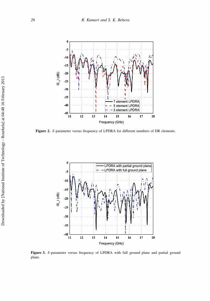
The simulation studies of the S -parameter versus frequency characteristics for the
proposed LPDRA have been carried out and are presented in Figure 2.
3.1. Parametric Study
The ensued bandwidth ranges from 11.4 to 18 GHz, which is the desired frequency range
for Ku-band applications. As discussed in Section 1, the gain, bandwidth, and radiation
performances of the DRA can be modified by using a log-periodic array instead of a
basic-shaped DRA.
An array of seven resonators (seven-element LPDRA) results in a wide impedance
bandwidth in comparison to five- and three-element DRAs. Figure 2 shows the S -
parameter versus frequency characteristics of the LPDRA for different numbers of ele-
ments (three, five, and seven). It can be realized from this plot that among all arrays,
only the array with seven elements provides a wide bandwidth from 11.4 to 18 GHz.
The detail performance of the LPDRA with different numbers of resonators is depicted
in Table 1.
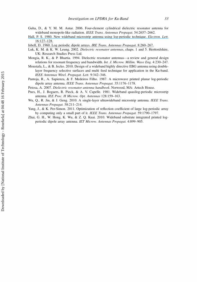
Similarly in the next design step, a partial ground plane was introduced instead of a
full ground plane to improve the resulted bandwidth. A parametric study is depicted in
Figure 3 for an LPDRA with a full ground plane and with a partial ground plane to achieve
Dow
nloa
ded
by [
Nat
iona
l Ins
titut
e of
Tec
hnol
ogy
- R
ourk
ela]
at 0
4:48
16
Febr
uary
201
5
26 R. Kumari and S. K. Behera
Figure 2. S-parameter versus frequency of LPDRA for different numbers of DR elements.
Figure 3. S-parameter versus frequency of LPDRA with full ground plane and partial ground
plane.
Dow
nloa
ded
by [
Nat
iona
l Ins
titut
e of
Tec
hnol
ogy
- R
ourk
ela]
at 0
4:48
16
Febr
uary
201
5

Investigation on LPDRA for Ku-Band 27
Table 1
Performance of LPDRA based on number of resonators in array
Number of resonators Bandwidth, jS11j < �10 dB (%) Gain (dBi)
3 9 8.3
5 35 10.6
7 46 11.4
the desired bandwidth. For the LPDRA with a full ground plane, impedance bandwidth
ranges up to 17 GHz, whereas for the partial ground plane, the desired bandwidth up to
18 GHz with S11 (dB) below �10 dB is perceived.
The S -parameter measurement of the fabricated LPDRA is performed using an
8720B Agilent network analyzer (IIT Roorkee, India). Figure 4 shows the simulated
and measured S -parameter (dB) as the function of frequency.
3.2. Bandwidth Response and Input Impedance Characteristics
It is observed in Figure 2 that the DRA bandwidth is directly influenced by the number of
elements used. Compared to the bandwidths of the three-, five-, and seven-element arrays,
the seven-element LPDRA provides the desired bandwidth. The bandwidth response and
gain of the LPDRA with a scaling factor 1.05 has also been compared with the LPDRA
with different scaling factors (0.9, 0.95, 1.0, and 1.1), as listed in Table 2.
An LPDRA with DRs having different dielectric constants is also simulated to check
the optimality of the proposed array. The performances of the LPDRA with different
dielectric materials are shown in Table 3. The bandwidth response of a DRA with different
materials is almost the same, but the preferred material for the proposed array is Teflon.
The Teflon-based dielectric materials are best suited for DRA design as they are not
prone to chipping compared to other dielectric materials.
Figure 4. Simulated and measured plots of S-parameter versus frequency for LPDRA.
Dow
nloa
ded
by [
Nat
iona
l Ins
titut
e of
Tec
hnol
ogy
- R
ourk
ela]
at 0
4:48
16
Febr
uary
201
5

28 R. Kumari and S. K. Behera
Table 2
Performances of LPDRA based on different values of scaling factor
Scaling factor (�) Bandwidth, jS11j < �10 dB (%) Gain (dBi)
0.9 35 8.89
0.95 35 9.42
1 27 10.05
1.05 46 11.4
1.1 34 8.96
Table 3
Performances of LPDRA based on dielectric constant of resonators
Dielectric constant ("r ) Bandwidth, jS11j < �10 dB (%) Gain (dBi)
2.1 46 11.4
6 47 10.7
9.8 46 10.75
10 46 11.2
Finally, the simulated and measured S -parameter of the seven-element LPDRA with
a scaling factor 1.05 have been plotted against frequency and are shown in Figure 4.
The resulting bandwidth is found to be 46%. The simulated and measured results of the
proposed LPDRA show a good approximation.
The real and imaginary parts of input impedance versus frequency curves of the
proposed antenna have been presented in Figure 5. The input resistance at resonant
frequencies of the LPDRA is found to be nearly 50 �, whereas the imaginary part of
Figure 5. Input impedance (Z) curve of LPDRA.
Dow
nloa
ded
by [
Nat
iona
l Ins
titut
e of
Tec
hnol
ogy
- R
ourk
ela]
at 0
4:48
16
Febr
uary
201
5

Investigation on LPDRA for Ku-Band 29
Table 4
Gain of log-periodic array with and without DRs
Structure
Simulated peak
gain (dBi)
Measured peak
gain (dBi)
LPDRA with DRs 11.75 11.4
Log-periodic array with 10.45 10.3
microstrip patches (without DRs)
the input impedance is zero, providing very good impedance match to a 50-� microstrip
line feed.
3.3. Gain of LPDRA
DRAs are far superior to microstrip antennas, as they have negligible metallic loss
and high efficiency at millimeter-wave frequencies. Due to low loss of the dielectric
materials, DRAs offer a high radiation efficiency as well as high gain in contradiction with
microstrip antenna. The proposed LPDRA is compared against a log-periodic microstrip
array without DRs, in which the DRs are replaced with microstrip patches. In an LPDRA,
DRs are the radiating elements, whereas in a log-periodic microstrip array, the patches
are radiating. In both cases, the array is radiating well, but the performance (in terms of
gain) of the LPDRA is superior compared to the log-periodic microstrip array, presented
in Table 4.
Figure 6 represents the simulated and measured gain versus frequency plots for the
log-periodic array with DRs and without DRs. From the plot, it is confirmed that within
the desired band, the gain of the DRA is better than the gain of the microstrip antenna.
In the case of a log-periodic microstrip array, a wide band can be achieved with low gain
and less radiation efficiency, as the conductor loss is greater compared to the LPDRA.
Figure 6. Simulated and measured gain of log-periodic antenna with and without DR.
Dow
nloa
ded
by [
Nat
iona
l Ins
titut
e of
Tec
hnol
ogy
- R
ourk
ela]
at 0
4:48
16
Febr
uary
201
5

30 R. Kumari and S. K. Behera
(a)
Figure 7. Simulated and measured co-polar and cross-polar radiation patterns of LPDRA: (a) y-z-
plane at 14 GHz, (b) y-z-plane at 16 GHz, (c) x-z-plane at 14 GHz, and (d) x-z-plane at 16 GHz.
(continued)
The gain characteristics of the LPDRA varies nearly log periodically between the ranges
of 9.4 to 11.4 dBi with 96% of radiation efficiency.
3.4. Radiation Pattern Characteristics
The radiation pattern measurements for the proposed LPDRA have been carried out inside
an anechoic chamber. The measured far-field radiation patterns of the proposed LPDRA
are almost the same for all frequencies.
Figure 7 plots the simulated and measured co-polar and cross-polar radiation patterns
in the y-z- and x-z-planes at different frequencies (14 and 16 GHz) for the log-periodic
array with DRs. It is observed that the H -plane radiation patterns are almost omnidi-
rectional and that the E-plane radiation patterns are nearly in the broadside direction
against frequency. The measured cross-polar rejection in the LPDRA is found to be
below �20 dB.
4. Conclusions
A wideband LPDRA with high radiation efficiency has been investigated. Good agreement
between simulation and measurement has been found. The matching is better than �10 dB
in the working bandwidth. With input match and radiation efficiency consideration, the
bandwidth of this antenna is 46% (11.4 to 18 GHz) with a voltage standing-wave ratio
(VSWR) less than 2. The maximum radiation efficiency of the proposed antenna is 96%,
providing a maximum gain of 11.4 dBi. This LPDRA design can be a good choice for
Ku-band applications.
Dow
nloa
ded
by [
Nat
iona
l Ins
titut
e of
Tec
hnol
ogy
- R
ourk
ela]
at 0
4:48
16
Febr
uary
201
5

Investigation on LPDRA for Ku-Band 31
(b)
(c)
Figure 7. (Continued).
Dow
nloa
ded
by [
Nat
iona
l Ins
titut
e of
Tec
hnol
ogy
- R
ourk
ela]
at 0
4:48
16
Febr
uary
201
5

32 R. Kumari and S. K. Behera
(d)
Figure 7. (Continued).
Acknowledgment
The authors would like to thank Mr. Rajeev Jyoti, Group Head Antenna Systems Group,
Space Applications Center (SAC) ISRO, Ahmedabad, India, for providing simulation
facilities in his antenna design laboratory. The authors would also like to thank Prof.
Amalendu Patnaik, Department of Electronics and Computer Engineering, IIT, Roorkee,
India, for providing measurement facilities in his microwave laboratory and Prof. R. K.
Mishra, Department of Electronic Science, Berhampur University, Odisha, India, for his
valuable suggestions during preparation of the article.
References
Balanis, C. A. 2005. Antenna theory: Analysis and design, chap. 11, 619–637. Hoboken, NJ: John
Wiley & Sons.
Borji, A., D. Busuioc, & S. Safavi-Naeini. 2009. Efficient, low-cost integrated waveguide-fed planar
antenna array for Ku-Band Applications. IEEE Antennas Wirel. Propagat. Lett. 8:336–339.
Carrel, J. 1961a. Some variations in log periodic antenna structures. IRE Trans. Antenna Propagat.
9:229–230.
Carrel, R. 1961b. The design of the log-periodic dipole antenna. IRE Int. Conv. Rec. 1:61–75.
Chen, S. Y., P. H. Wang, & P. Hsu. 2006. Uniplanar log-periodic slot antenna fed by a CPW for
UWB applications. IEEE Antennas Wirel. Propagat. Lett. 5:256–259.
Drossos, G., Z. Wu, & L. E. Davis. 1998. Four-element planar arrays employing probe-fed
cylindrical dielectric resonator antennas. Microw. Opt. Technol. Lett. 18:315–319.
Ghassemi, N., K. Wu, S. Claude, X. Zhang, & J. Bornemann. 2011. Compact coplanar waveguide
spiral antenna with circular polarization for wideband applications. IEEE Antennas Wirel.
Propagat. Lett. 10:666–669.
Dow
nloa
ded
by [
Nat
iona
l Ins
titut
e of
Tec
hnol
ogy
- R
ourk
ela]
at 0
4:48
16
Febr
uary
201
5
Investigation on LPDRA for Ku-Band 33
Guha, D., & Y. M. M. Antar. 2006. Four-element cylindrical dielectric resonator antenna for
wideband monopole-like radiation. IEEE Trans. Antennas Propagat. 54:2657–2662.
Hall, P. S. 1980. New wideband microstrip antenna using log-periodic technique. Electron. Lett.
16:127–128.
Isbell, D. 1960. Log periodic dipole arrays. IRE Trans. Antennas Propagat. 8:260–267.
Luk, K. M. & K. W. Leung. 2002. Dielectric resonator antennas, chaps. 1 and 5. Herttordshire,
UK: Research Studies Press Ltd.
Mongia, R. K., & P. Bhartia. 1994. Dielectric resonator antennas—a review and general design
relations for resonant frequency and bandwidth. Int. J. Microw. Millim. Wave Eng. 4:230–247.
Moustafa, L., & B. Jecko. 2010. Design of a wideband highly directive EBG antenna using double-
layer frequency selective surfaces and multi feed technique for application in the Ku-band.
IEEE Antennas Wirel. Propagat. Lett. 9:342–346.
Pantoja, R., A. Sapienza, & F. Medeiros Filho. 1987. A microwave printed planar log-periodic
dipole array antenna. IEEE Trans. Antennas Propagat. 35:1176–1178.
Petosa, A. 2007. Dielectric resonator antenna handbook. Norwood, MA: Artech House.
Pues, H., J. Bogaers, R. Pieck, & A. V. Capelle. 1981. Wideband quasilog-periodic microstrip
antenna. IEE Proc. H Microw. Opt. Antennas 128:159–163.
Wu, Q., R. Jin, & J. Geng. 2010. A single-layer ultrawideband microstrip antenna. IEEE Trans.
Antennas Propagat. 58:211–214.
Yang, J., & K. Per-Simon. 2011. Optimization of reflection coefficient of large log-periodic array
by computing only a small part of it. IEEE Trans. Antennas Propagat. 59:1790–1797.
Zhai, G. H., W. Hong, K. Wu, & Z. Q. Kuai. 2010. Wideband substrate integrated printed log-
periodic dipole array antenna. IET Microw. Antennas Propagat. 4:899–905.
Dow
nloa
ded
by [
Nat
iona
l Ins
titut
e of
Tec
hnol
ogy
- R
ourk
ela]
at 0
4:48
16
Febr
uary
201
5