Investigation of Tunnel Face Stability and Deformation using Critical State Plasticity
10
2 nd Eastern European Tunnelling Conference Athens, Greece “Tunnelling in a Challenging Environment” 28 September - 01 October 2014 Making tunnelling business in difficult times Greek Tunnelling Society - 1 - Investigation of Tunnel Face Stability and Deformation using Critical State Plasticity P. Sitarenios 1 , G. Kallivokas 1 , G. Prountzopoulos 1 , A. Kalos 1 & M. Kavvadas 1 1 National Technical University of Athens, Athens, Greece [email protected] ABSTRACT: The behaviour of the excavation face is one of the most critical aspects in urban tunnels excavated with conventional methods (i.e., not with TBMs), as the majority of such failures are due to excessive face extrusion, often leading to face collapse. This paper investigates the stability conditions and deformational behaviour of an unsupported tunnel face through an extensive set of three dimensional finite element analyses. The Modified Cam-Clay constitutive model is used in modelling the behaviour of the ground. The obtained results are used in understanding how various geometrical (tunnel diameter, depth of overburden), as well as geotechnical conditions (ground strength and compressibility) affect the behaviour of the tunnel face. Using these results, face stability is quantified in terms of the magnitude of face extrusion by correlating an average normalized face extrusion with a face stability factor similar to that proposed by Prountzopoulos (2012). Finally, an attempt is made to calculate the factor of safety (FS) of an unsupported tunnel face. Keywords: Tunnel Face Stability, Face extrusion, Modified Cam - Clay 1 Introduction Controlling the axial deformation (extrusion) of tunnel face is probably one of the most important issues in tunnelling, as most tunnel failures and most unsuccessful applications of both non- mechanized and TBM tunnelling can be attributed to poor control of tunnel face. The study of face stability conditions of an unsupported tunnel face has long been based on either experimental investigations (see Meguit et.al 2007) or on limit analyses methods (e.g. Anagnostou & Kovari, 1994). Experimental results usually have limited applicability due to the fact that they are focused in special geometrical and geotechnical conditions while both methods focus in predicting the conditions at incipient face instability. Three dimensional (3D) numerical analyses are constantly gaining power as they allow for the prediction of the magnitude of deformation in both "stable" and "unstable" face conditions. The deformation of the advance core (near-face region) plays a crucial role in face stability and a lot of researches have tried to approach the issue of face stability from a deformational perspective, through 3D numerical analyses (e.g. Prountzopoulos & Kavvadas, 2014; Prountzopoulos, 2012). In this paper the deformational behaviour and face stability of an unsupported tunnel face is investigated through 3D numerical analyses using a methodology similar to the one proposed by Prountzopoulos (2012). The novelty of the present work lies in the use of the Modified Cam Clay constitutive model in describing the stress strain relationship of the excavated geomaterial, instead of the usually utilized elastic - perfectly plastic Mohr - Coulomb model. In the following sections, the work of Prountzopoulos (2012) is briefly reviewed and the key differences between Mohr-Coulomb and Modified Cam-Clay constitutive models are highlighted. Then the results of the numerical investigation performed are used in a) a qualitative assessment of the effect that different geotechnical and geometrical conditions have on face extrusion and; b) in the prediction of face stability conditions.
Transcript of Investigation of Tunnel Face Stability and Deformation using Critical State Plasticity
2nd Eastern European Tunnelling Conference Athens, Greece “Tunnelling in a Challenging Environment” 28 September - 01 October 2014 Making tunnelling business in difficult times Greek Tunnelling Society
- 1 -
Investigation of Tunnel Face Stability and Deformation using Critical State Plasticity
P. Sitarenios1, G. Kallivokas1, G. Prountzopoulos1, A. Kalos1 & M. Kavvadas1
1National Technical University of Athens, Athens, Greece
ABSTRACT: The behaviour of the excavation face is one of the most critical aspects in urban tunnels excavated
with conventional methods (i.e., not with TBMs), as the majority of such failures are due to excessive face
extrusion, often leading to face collapse. This paper investigates the stability conditions and deformational
behaviour of an unsupported tunnel face through an extensive set of three dimensional finite element analyses.
The Modified Cam-Clay constitutive model is used in modelling the behaviour of the ground. The obtained results
are used in understanding how various geometrical (tunnel diameter, depth of overburden), as well as
geotechnical conditions (ground strength and compressibility) affect the behaviour of the tunnel face. Using these
results, face stability is quantified in terms of the magnitude of face extrusion by correlating an average
normalized face extrusion with a face stability factor similar to that proposed by Prountzopoulos (2012). Finally,
an attempt is made to calculate the factor of safety (FS) of an unsupported tunnel face.
Keywords: Tunnel Face Stability, Face extrusion, Modified Cam - Clay
1 Introduction
Controlling the axial deformation (extrusion) of tunnel face is probably one of the most important
issues in tunnelling, as most tunnel failures and most unsuccessful applications of both non-
mechanized and TBM tunnelling can be attributed to poor control of tunnel face.
The study of face stability conditions of an unsupported tunnel face has long been based on either
experimental investigations (see Meguit et.al 2007) or on limit analyses methods (e.g. Anagnostou &
Kovari, 1994). Experimental results usually have limited applicability due to the fact that they are
focused in special geometrical and geotechnical conditions while both methods focus in predicting the
conditions at incipient face instability.
Three dimensional (3D) numerical analyses are constantly gaining power as they allow for the
prediction of the magnitude of deformation in both "stable" and "unstable" face conditions. The
deformation of the advance core (near-face region) plays a crucial role in face stability and a lot of
researches have tried to approach the issue of face stability from a deformational perspective, through
3D numerical analyses (e.g. Prountzopoulos & Kavvadas, 2014; Prountzopoulos, 2012).
In this paper the deformational behaviour and face stability of an unsupported tunnel face is
investigated through 3D numerical analyses using a methodology similar to the one proposed by
Prountzopoulos (2012). The novelty of the present work lies in the use of the Modified Cam Clay
constitutive model in describing the stress strain relationship of the excavated geomaterial, instead of
the usually utilized elastic - perfectly plastic Mohr - Coulomb model.
In the following sections, the work of Prountzopoulos (2012) is briefly reviewed and the key differences
between Mohr-Coulomb and Modified Cam-Clay constitutive models are highlighted. Then the results
of the numerical investigation performed are used in a) a qualitative assessment of the effect that
different geotechnical and geometrical conditions have on face extrusion and; b) in the prediction of
face stability conditions.
Sitarenios et al.
- 2 -
2 Approaching face stability through deformation (extrusion)
In an attempt to correlate the stability conditions of an unsupported tunnel face with axial face
deformation, Prountzopoulos (2012) conducted an extensive numerical investigation, comprising more
that four hundred 3D numerical analyses for different geometrical (tunnel diameter D, depth of
overburden H) and geotechnical (cohesion c, angle of internal friction φ, Elastic Modulus Ε) conditions.
The ABAQUS finite element code was used in conjunction with the elastic perfectly-plastic Mohr-
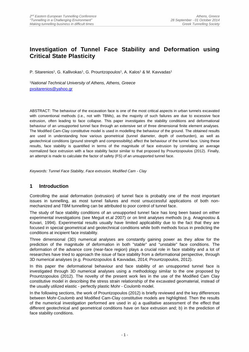
Coulomb (M-C) constitutive model. Figure 1 plots the results of this extensive 3D parametrical study.
Figure 1. Results of the normalized face extrusion ploted versus Face Stability Parameter ΛF for H/D≤5
(after Prountzopoulos, 2012).
In figure 1, in the vertical axis, results of the normalized face extrusion are given utilizing the
normalized parameter Ωf,Area given by the following expression:
,
,
0
h Area soil
F Area
U E
D PΩ
(1)
Uh,Area is the average face area extrusion derived when volume of extrusion is divided with the area of
the tunnel face, D is the tunnel diameter, Esoil the ground modulus and P0 the average stress in the
tunnel axis level P0 =γΗ(1+Κ)/2, with (γΗ) being the overburden pressure and K the geostatic stress
ratio. Normalized extrusion is plotted against a new face stability parameter ΛF:
2
1
5.25 tan (45 )2
F b b
c
D
αφ
γΛ
Η
(2)
which includes ground strength (in terms of cohesion c and friction φ) in the numerator and also the
combined effects of tunnel depth H and diameter D both explicitly (eq.2) and implicitly through the
coefficients α and b, given by the following expressions:
59.016.0 D
H
(3)
37.0
D
Hb
(4)
It is observed that the proposed normalized expressions achieve practical uniqueness for a wide
range of ground properties, tunnel diameters and depths. Furthermore, face instability (i.e., where the
slope of the face extrusion curve increases rapidly) occurs when the Face Stability Parameter ΛF is
less than one (ΛF<1).
Sitarenios et al.
- 3 -
Using face extrusion, a deformational quantity, in assessing face stability means that the obtained
correlations are as reliable as the calculated strain field, i.e., as the constitutive model used. It is well
known that the Mohr-Coulomb elastic perfectly plastic model, although extensively used due to its
simplicity (well known parameters c, φ, E), fails in reproducing realistic plastic strains. This is mainly
attributed to the fact that a strength criterion is used to describe the yield envelope and thus failure
and yield coincide, meaning that plastic strain appears only when failure conditions have been
reached. It is well known that this is far from reality for soils where plastic deformation occurs even in
the small strain regime. Moreover the plastic dilatancy reproduced is constant and must be
preselected to match the desired behavior (contractant or dilatant), while radial stress paths that do
not lead to failure (i.e., isotopic consolidation, K0 consolidation) are assumed as purely elastic.
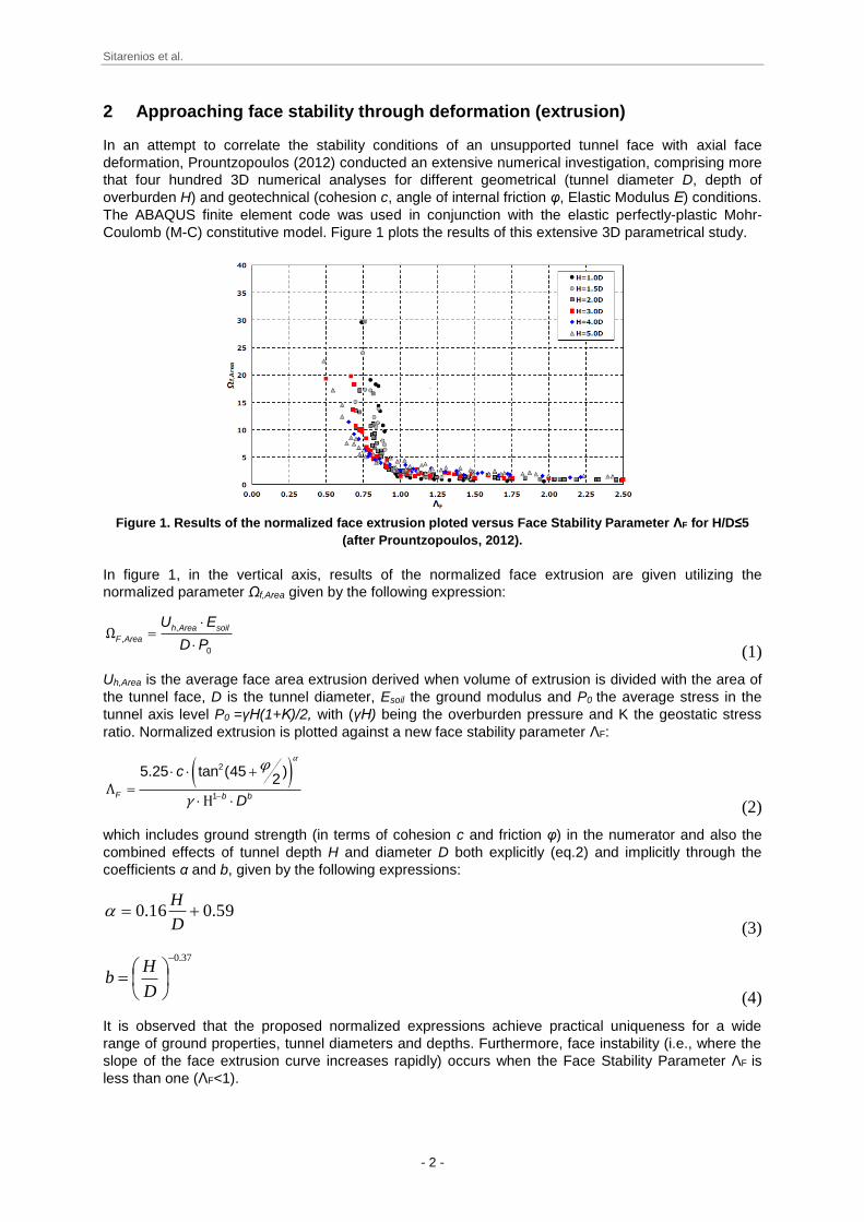
On the contrary, the Modified Cam Clay (MCC) model (Roscoe & Burland, 1968) is a closed yield
surface, hardening model. Figure 2 depicts the yield surface of the MCC model in the mean effective
stress (p') - deviatoric stress (q) plane and also the corresponding compressibility framework in the
specific volume (v) - natural logarithm of the mean effective stress (lnp') plane.
Figure 2. a) The MCC yield surface in the p'-q plane and b) the underlying compressibility framework in
the v-lnp' plane.
As shown in figure 2, the MCC's yield surface is an ellipsoid with its main axis aligned with the
hydrostatic axis; in the triaxial stress space, it is described by the following yield function :
2 2
m m(p,q,p ) p p 0f q M p (5)
M is the slope of the critical state line in the p-q plane and pm is the hardening variable representing
the isotropic pre-consolidation pressure. An associated flow rule is assumed, while an isotropic
hardening rule is utilized to provide the evolution of the yield surface with plastic loading. MCC's
hardening rule describes an increase (or decrease) in the size of the yield surface, which is assumed
incrementally linear to the corresponding plastic volumetric strain increment, through the following
expression:
p
m m vol
vp p ε
λ κΔ Δ
(6)
where v, pm are the specific volume and the pre-consolidation pressure in the begining of the
increment, respectively, while κ, λ are compressibility parameters.
In the MCC model, yield is separated from failure, while the later is associated with the critical state,
corresponding to the accumulation of potentially infinite deviatoric strains under constant volume. The
simulated material may strain-harden or strain-soften prior to failure and thus peak strength does not
necessarily coincide with the residual strength (strength at failure).
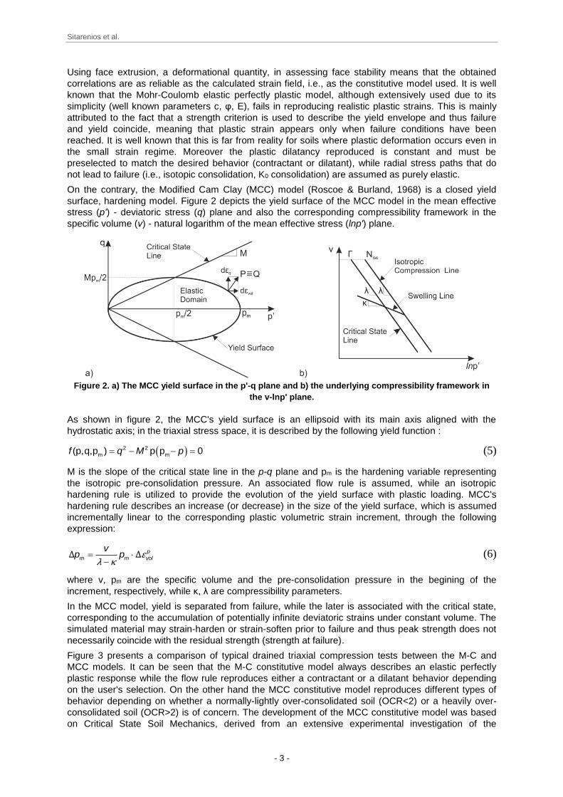
Figure 3 presents a comparison of typical drained triaxial compression tests between the M-C and
MCC models. It can be seen that the M-C constitutive model always describes an elastic perfectly
plastic response while the flow rule reproduces either a contractant or a dilatant behavior depending
on the user's selection. On the other hand the MCC constitutive model reproduces different types of
behavior depending on whether a normally-lightly over-consolidated soil (OCR<2) or a heavily over-
consolidated soil (OCR>2) is of concern. The development of the MCC constitutive model was based
on Critical State Soil Mechanics, derived from an extensive experimental investigation of the
Sitarenios et al.
- 4 -
mechanical behavior of structure-less soils. Although it still cannot account for primary anisotropy or
structural effects usually observed in natural soil deposits, it is superior to the M-C constitutive model,
in the sense that its predictions are based on a sound geotechnical framework.
Figure 3. Typical drained triaxial compression tests and the predicted stress - strain relationship with the
a) elastic perfectly plastic M-C and b) the MCC constitutive models.
3 Numerical Investigation
3.1 Finite element model
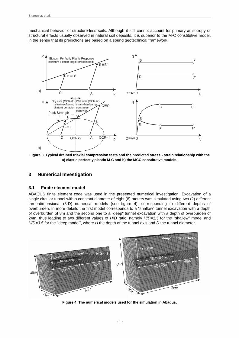
ABAQUS finite element code was used in the presented numerical investigation. Excavation of a
single circular tunnel with a constant diameter of eight (8) meters was simulated using two (2) different
three-dimensional (3-D) numerical models (see figure 4), corresponding to different depths of
overburden. In more details the first model corresponds to a "shallow" tunnel excavation with a depth
of overburden of 8m and the second one to a "deep" tunnel excavation with a depth of overburden of
24m, thus leading to two different values of H/D ratio, namely H/D=1.5 for the "shallow" model and
H/D=3.5 for the "deep model", where H the depth of the tunnel axis and D the tunnel diameter.
Figure 4. The numerical models used for the simulation in Abaqus.
Sitarenios et al.
- 5 -
The geotechnical conditions have been assumed to vary only with depth and thus a symmetrical (with
respect to a vertical plane parallel to the tunnel axis) boundary value problem is of concern, leading to
a reduced computational cost as only half of the model needs to be simulated. Eight-noded linear
elements were used to form the required 3D finite element mesh. A dense discretization has been
selected for the areas close to the tunnel, with an average characteristic element length of just 1m,
while a coarser grid is used towards the boundaries (max characteristic element length of 4m).
Finally, the MCC constitutive model was utilized to provide the necessary stress - strain relationship of
the simulated geomaterial.
3.2 Geometrical and geotechnical conditions simulated
The deformational behaviour of tunnel face depends on both the geometrical (depth of overburden)
and on the geotechnical conditions encountered during excavation. Hence, in an attempt to include in
the investigation a representative quantity of different excavation conditions, seventy two (72)
numerical analyses were executed. They were divided in two individual sets, the first one
corresponding to the "shallow" tunnel and the second one to the "deep" tunnel. Thirty six (36)
analyses were performed for each set, corresponding to different combinations of MCC strength and
deformability parameters. Table 1 shows a summary of the different geometrical and geotechnical
conditions assumed in the presented numerical investigation.
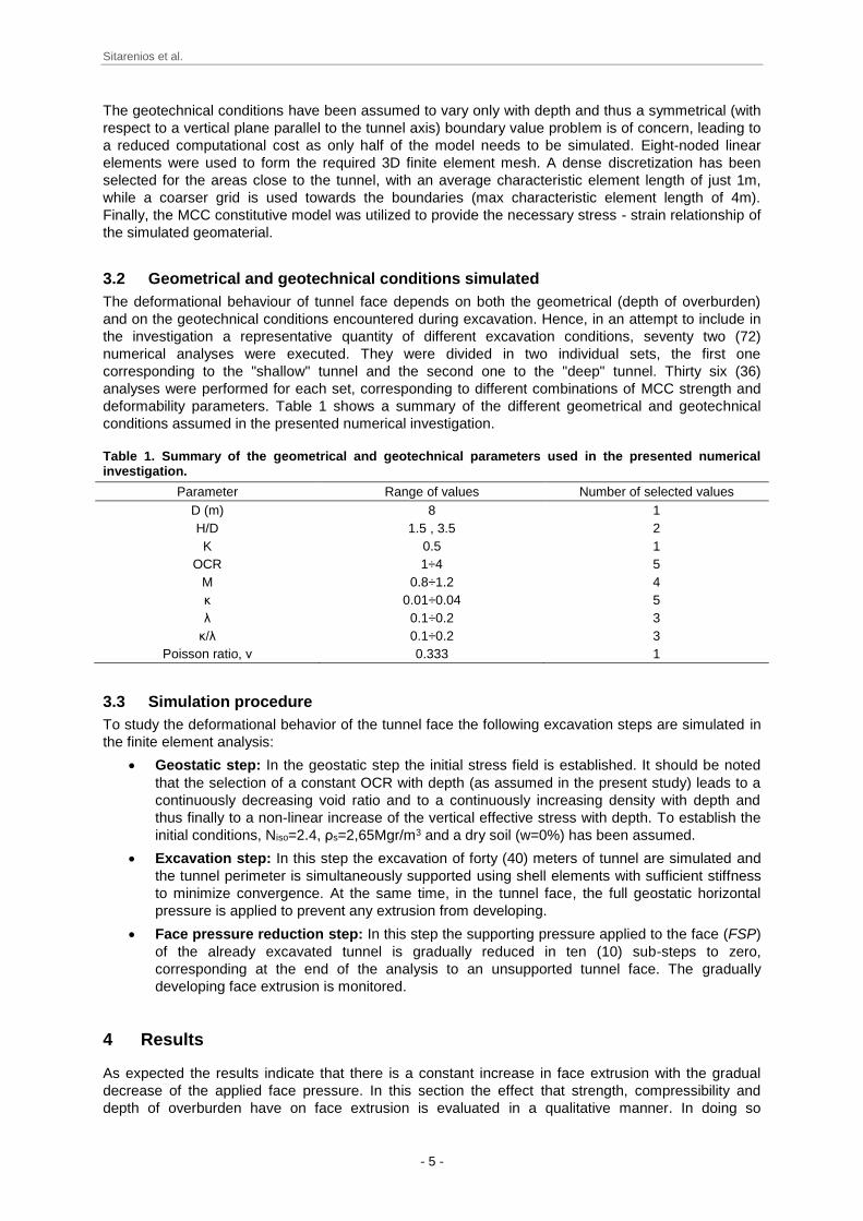
Table 1. Summary of the geometrical and geotechnical parameters used in the presented numerical investigation.
Parameter Range of values Number of selected values
D (m) 8 1
H/D 1.5 , 3.5 2
K 0.5 1
OCR 1÷4 5
M 0.8÷1.2 4
κ 0.01÷0.04 5
λ 0.1÷0.2 3
κ/λ 0.1÷0.2 3
Poisson ratio, ν 0.333 1
3.3 Simulation procedure
To study the deformational behavior of the tunnel face the following excavation steps are simulated in
the finite element analysis:
Geostatic step: In the geostatic step the initial stress field is established. It should be noted
that the selection of a constant OCR with depth (as assumed in the present study) leads to a
continuously decreasing void ratio and to a continuously increasing density with depth and
thus finally to a non-linear increase of the vertical effective stress with depth. To establish the
initial conditions, Niso=2.4, ρs=2,65Mgr/m3 and a dry soil (w=0%) has been assumed.
Excavation step: In this step the excavation of forty (40) meters of tunnel are simulated and
the tunnel perimeter is simultaneously supported using shell elements with sufficient stiffness
to minimize convergence. At the same time, in the tunnel face, the full geostatic horizontal
pressure is applied to prevent any extrusion from developing.
Face pressure reduction step: In this step the supporting pressure applied to the face (FSP)
of the already excavated tunnel is gradually reduced in ten (10) sub-steps to zero,
corresponding at the end of the analysis to an unsupported tunnel face. The gradually
developing face extrusion is monitored.
4 Results
As expected the results indicate that there is a constant increase in face extrusion with the gradual
decrease of the applied face pressure. In this section the effect that strength, compressibility and
depth of overburden have on face extrusion is evaluated in a qualitative manner. In doing so
Sitarenios et al.
- 6 -
normalized diagrams of the evolution of the average face extrusion with the decrease of the applied
pressure have been used.
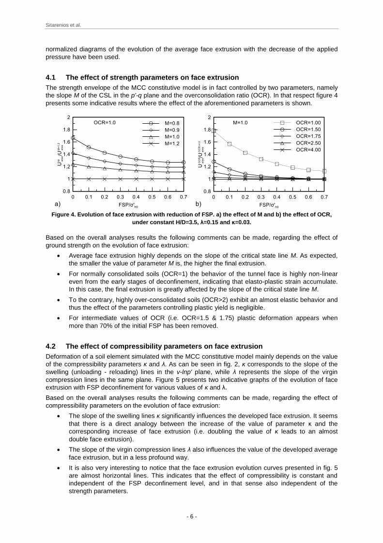
4.1 The effect of strength parameters on face extrusion
The strength envelope of the MCC constitutive model is in fact controlled by two parameters, namely
the slope M of the CSL in the p'-q plane and the overconsolidation ratio (OCR). In that respect figure 4
presents some indicative results where the effect of the aforementioned parameters is shown.
Figure 4. Evolution of face extrusion with reduction of FSP. a) the effect of M and b) the effect of OCR,
under constant H/D=3.5, λ=0.15 and κ=0.03.
Based on the overall analyses results the following comments can be made, regarding the effect of
ground strength on the evolution of face extrusion:
Average face extrusion highly depends on the slope of the critical state line M. As expected,
the smaller the value of parameter M is, the higher the final extrusion.
For normally consolidated soils (OCR=1) the behavior of the tunnel face is highly non-linear
even from the early stages of deconfinement, indicating that elasto-plastic strain accumulate.
In this case, the final extrusion is greatly affected by the slope of the critical state line M.
To the contrary, highly over-consolidated soils (OCR>2) exhibit an almost elastic behavior and
thus the effect of the parameters controlling plastic yield is negligible.
For intermediate values of OCR (i.e. OCR=1.5 & 1.75) plastic deformation appears when
more than 70% of the initial FSP has been removed.
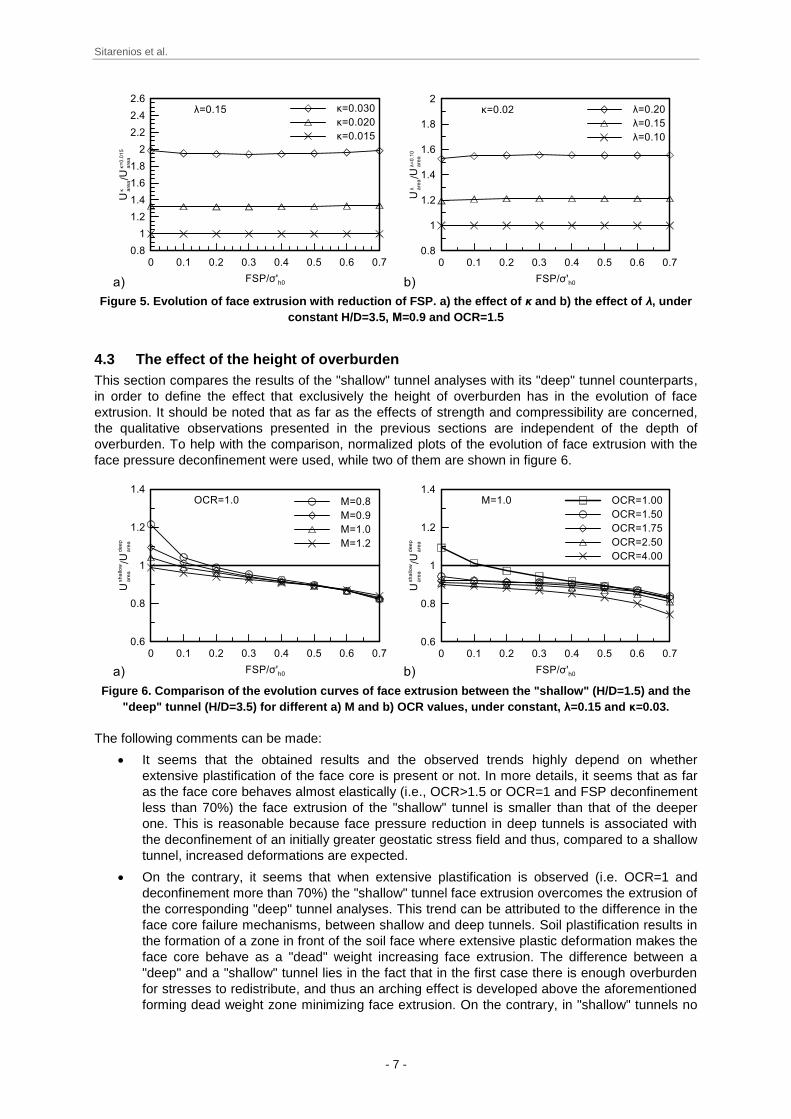
4.2 The effect of compressibility parameters on face extrusion
Deformation of a soil element simulated with the MCC constitutive model mainly depends on the value
of the compressibility parameters κ and λ. As can be seen in fig. 2, κ corresponds to the slope of the
swelling (unloading - reloading) lines in the v-lnp' plane, while λ represents the slope of the virgin
compression lines in the same plane. Figure 5 presents two indicative graphs of the evolution of face
extrusion with FSP deconfinement for various values of κ and λ.
Based on the overall analyses results the following comments can be made, regarding the effect of
compressibility parameters on the evolution of face extrusion:
The slope of the swelling lines κ significantly influences the developed face extrusion. It seems
that there is a direct analogy between the increase of the value of parameter κ and the
corresponding increase of face extrusion (i.e. doubling the value of κ leads to an almost
double face extrusion).
The slope of the virgin compression lines λ also influences the value of the developed average
face extrusion, but in a less profound way.
It is also very interesting to notice that the face extrusion evolution curves presented in fig. 5
are almost horizontal lines. This indicates that the effect of compressibility is constant and
independent of the FSP deconfinement level, and in that sense also independent of the
strength parameters.
Sitarenios et al.
- 7 -
Figure 5. Evolution of face extrusion with reduction of FSP. a) the effect of κ and b) the effect of λ, under
constant H/D=3.5, Μ=0.9 and OCR=1.5
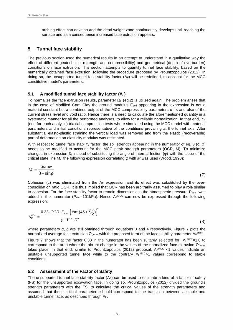
4.3 The effect of the height of overburden
This section compares the results of the "shallow" tunnel analyses with its "deep" tunnel counterparts,
in order to define the effect that exclusively the height of overburden has in the evolution of face
extrusion. It should be noted that as far as the effects of strength and compressibility are concerned,
the qualitative observations presented in the previous sections are independent of the depth of
overburden. To help with the comparison, normalized plots of the evolution of face extrusion with the
face pressure deconfinement were used, while two of them are shown in figure 6.
Figure 6. Comparison of the evolution curves of face extrusion between the "shallow" (H/D=1.5) and the
"deep" tunnel (H/D=3.5) for different a) M and b) OCR values, under constant, λ=0.15 and κ=0.03.
The following comments can be made:
It seems that the obtained results and the observed trends highly depend on whether
extensive plastification of the face core is present or not. In more details, it seems that as far
as the face core behaves almost elastically (i.e., OCR>1.5 or OCR=1 and FSP deconfinement
less than 70%) the face extrusion of the "shallow" tunnel is smaller than that of the deeper
one. This is reasonable because face pressure reduction in deep tunnels is associated with
the deconfinement of an initially greater geostatic stress field and thus, compared to a shallow
tunnel, increased deformations are expected.
On the contrary, it seems that when extensive plastification is observed (i.e. OCR=1 and
deconfinement more than 70%) the "shallow" tunnel face extrusion overcomes the extrusion of
the corresponding "deep" tunnel analyses. This trend can be attributed to the difference in the
face core failure mechanisms, between shallow and deep tunnels. Soil plastification results in
the formation of a zone in front of the soil face where extensive plastic deformation makes the
face core behave as a "dead" weight increasing face extrusion. The difference between a
"deep" and a "shallow" tunnel lies in the fact that in the first case there is enough overburden
for stresses to redistribute, and thus an arching effect is developed above the aforementioned
forming dead weight zone minimizing face extrusion. On the contrary, in "shallow" tunnels no
Sitarenios et al.
- 8 -
arching effect can develop and the dead weight zone continuously develops until reaching the
surface and as a consequence increased face extrusion appears.
5 Tunnel face stability
The previous section used the numerical results in an attempt to understand in a qualitative way the
effect of different geotechnical (strength and compressibility) and geometrical (depth of overburden)
conditions on face extrusion. This section attempts to quantify tunnel face stability, based on the
numerically obtained face extrusion, following the procedure proposed by Prountzopoulos (2012). In
doing so, the unsupported tunnel face stability factor (ΛF) will be redefined, to account for the MCC
constitutive model's parameters.
5.1 A modified tunnel face stability factor (ΛF)
To normalize the face extrusion results, parameter ΩF (eq.2) is utilized again. The problem arises that
in the case of Modified Cam Clay the ground modulus Esoil appearing in the expression is not a
material constant but a combined output of the MCC compressibility parameters κ , λ and also of the
current stress level and void ratio. Hence there is a need to calculate the aforementioned quantity in a
systematic manner for all the performed analyses, to allow for a reliable normalization. In that end, 72
(one for each analysis) triaxial compression tests where simulated using the MCC model with material
parameters and initial conditions representative of the conditions prevailing at the tunnel axis. After
substantial elasto-plastic straining the vertical load was removed and from the elastic (recoverable)
part of deformation an elasticity modulus was estimated.
With respect to tunnel face stability factor, the soil strength appearing in the numerator of eq. 3 (c, φ)
needs to be modified to account for the MCC peak strength parameters (OCR, M). To minimize
changes in expression 3, instead of substituting the angle of internal friction (φ) with the slope of the
critical state line M, the following expression correlating φ with M was used (Wood, 1990):
sin3
sin6
M
(7)
Cohesion (c) was eliminated from the ΛF expression and its effect was substituted by the over-
consolidation ratio OCR. It is thus implied that OCR has been arbitrarily assumed to play a role similar
to cohesion. For the face stability factor to remain dimensionless the atmospheric pressure Patm was
added in the numerator (Patm=101kPa). Hence ΛFMCC can now be expressed through the following
expression:
2
1
0.33 tan (45 )2atm
MCC
F b b
OCR P
D
αφ
γΛ
Η
(8)
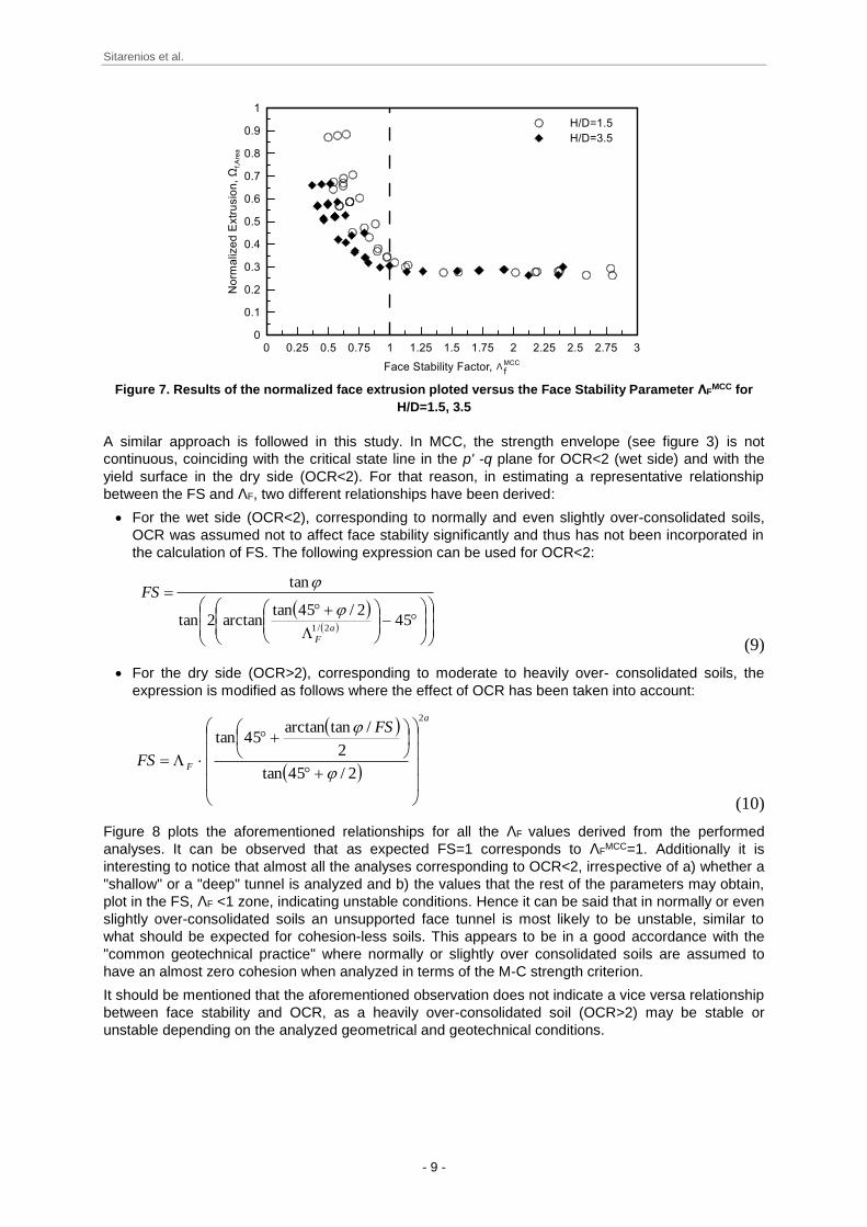
where parameters α, b are still obtained through equations 3 and 4 respectively. Figure 7 plots the
normalized average face extrusion Ωf,Area with the proposed form of the face stability parameter ΛFMCC.
Figure 7 shows that the factor 0.33 in the numerator has been suitably selected for ΛFMCC=1.0 to
correspond to the area where the abrupt change in the values of the normalized face extrusion Ωf,Area
takes place. In that end, similar to Prountzopoulos (2012) proposal, ΛFMCC <1 values indicate an
unstable unsupported tunnel face while to the contrary ΛFMCC>1 values correspond to stable
conditions.
5.2 Assessment of the Factor of Safety
The unsupported tunnel face stability factor (ΛF) can be used to estimate a kind of a factor of safety
(FS) for the unsupported excavation face. In doing so, Prountzopoulos (2012) divided the ground's
strength parameters with the FS, to calculate the critical values of the strength parameters and
assumed that these critical parameters should correspond to the transition between a stable and
unstable tunnel face, as described through ΛF.
Sitarenios et al.
- 9 -
Figure 7. Results of the normalized face extrusion ploted versus the Face Stability Parameter ΛF
MCC for
H/D=1.5, 3.5
A similar approach is followed in this study. In MCC, the strength envelope (see figure 3) is not
continuous, coinciding with the critical state line in the p' -q plane for OCR<2 (wet side) and with the
yield surface in the dry side (OCR<2). For that reason, in estimating a representative relationship
between the FS and ΛF, two different relationships have been derived:
For the wet side (OCR<2), corresponding to normally and even slightly over-consolidated soils,
OCR was assumed not to affect face stability significantly and thus has not been incorporated in
the calculation of FS. The following expression can be used for OCR<2:
452/45tan
arctan2tan
tan
2/1 a
F
FS
(9)
For the dry side (OCR>2), corresponding to moderate to heavily over- consolidated soils, the
expression is modified as follows where the effect of OCR has been taken into account:
a
F
FS
FS
2
2/45tan
2
/tanarctan45tan
(10)
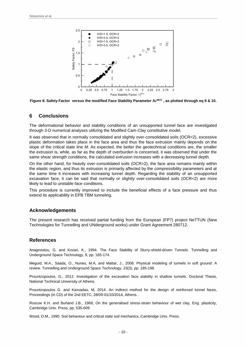
Figure 8 plots the aforementioned relationships for all the ΛF values derived from the performed
analyses. It can be observed that as expected FS=1 corresponds to ΛFMCC=1. Additionally it is
interesting to notice that almost all the analyses corresponding to OCR<2, irrespective of a) whether a
"shallow" or a "deep" tunnel is analyzed and b) the values that the rest of the parameters may obtain,
plot in the FS, ΛF <1 zone, indicating unstable conditions. Hence it can be said that in normally or even
slightly over-consolidated soils an unsupported face tunnel is most likely to be unstable, similar to
what should be expected for cohesion-less soils. This appears to be in a good accordance with the
"common geotechnical practice" where normally or slightly over consolidated soils are assumed to
have an almost zero cohesion when analyzed in terms of the M-C strength criterion.
It should be mentioned that the aforementioned observation does not indicate a vice versa relationship
between face stability and OCR, as a heavily over-consolidated soil (OCR>2) may be stable or
unstable depending on the analyzed geometrical and geotechnical conditions.
Sitarenios et al.
- 10 -
Figure 8. Safety Factor versus the modified Face Stability Parameter ΛF
MCC , as plotted through eq 9 & 10.
6 Conclusions
The deformational behavior and stability conditions of an unsupported tunnel face are investigated
through 3-D numerical analyses utilizing the Modified Cam-Clay constitutive model.
It was observed that in normally consolidated and slightly over-consolidated soils (OCR<2), excessive
plastic deformation takes place in the face area and thus the face extrusion mainly depends on the
slope of the critical state line M. As expected, the better the geotechnical conditions are, the smaller
the extrusion is, while, as far as the depth of overburden is concerned, it was observed that under the
same shear strength conditions, the calculated extrusion increases with a decreasing tunnel depth.
On the other hand, for heavily over-consolidated soils (OCR>2), the face area remains mainly within
the elastic region, and thus its extrusion is primarily affected by the compressibility parameters and at
the same time it increases with increasing tunnel depth. Regarding the stability of an unsupported
excavation face, it can be said that normally or slightly over-consolidated soils (OCR<2) are more
likely to lead to unstable face conditions.
This procedure is currently improved to include the beneficial effects of a face pressure and thus
extend its applicability in EPB TBM tunneling.
Acknowledgements
The present research has received partial funding from the European (FP7) project NeTTUN (New
Technologies for Tunnelling and UNderground works) under Grant Agreement 280712.
References
Anagnostou, G. and Kovari, K., 1994. The Face Stability of Slurry-shield-driven Tunnels. Tunnelling and
Underground Space Technology, 9, pp. 165-174.
Meguid, M.A., Saada, O., Nunes, M.A, and Mattar, J., 2008. Physical modeling of tunnels in soft ground: A
review. Tunnelling and Underground Space Technology, 23(3), pp. 185-198.
Prountzopoulos, G., 2012. Investigation of the excavation face stability in shallow tunnels. Doctoral Thesis,
National Technical University of Athens.
Prountzopoulos G. and Kavvadas, M, 2014. An indirect method for the design of reinforced tunnel faces,
Proceedings (in CD) of the 2nd EETC, 28/09-01/10/2014, Athens.
Roscoe K.H. and Burland J.B., 1968, On the generalised stress-strain behaviour of wet clay, Eng. plasticity,
Cambridge Univ. Press, pp. 535-609
Wood, D.M., 1990. Soil behaviour and critical state soil mechanics, Cambridge Univ. Press.