Installation and Monitoring of Shotcrete Pillars at Newmont ...

Acta Materialia 98 (2015) 391–404
Contents lists available at ScienceDirect
Acta Materialia
journal homepage: www.elsevier .com/locate /actamat
Size and orientation effects in partial dislocation-mediated deformationof twinning-induced plasticity steel micro-pillars
http://dx.doi.org/10.1016/j.actamat.2015.06.0651359-6454/� 2015 Acta Materialia Inc. Published by Elsevier Ltd. All rights reserved.
⇑ Corresponding author.E-mail address: [email protected] (B.C. De Cooman).
Won Seok Choi a, Bruno C. De Cooman a,⇑, Stefanie Sandlöbes b, Dierk Raabe b
a Graduate Institute of Ferrous Technology, Pohang University of Science and Technology, Pohang, Republic of Koreab Max-Planck-Institut für Eisenforschung GmbH, Düsseldorf, Germany
a r t i c l e i n f o
Article history:Received 22 January 2015Revised 14 April 2015Accepted 5 June 2015Available online 8 August 2015
Keywords:TWIP steelMicro-pillarMicro-compressionTwinningTwin nucleation
a b s t r a c t
Bulk and micro-pillar single crystals were used to investigate the twinning-induced plasticity mechanismin austenitic Fe-22 wt%Mn-0.6 wt%C TWIP steel. Compression of micro-pillars oriented either fordeformation-induced twinning or for perfect dislocation glide was carried out for pillars with diametersin the range of 600 nm to 4 lm. The same size dependence of the critical resolved shear stress wasobserved for both orientations. The critical micro-pillar diameter for size-independent plasticity wasapproximately 7.6 lm. Partial dislocation-mediated formation of twins and e-martensite was observedin micro-pillars oriented for twinning by transmission electron microscopy. The elastic–plastic transitionin micro-pillars oriented for deformation twinning did not involve twinning, and dislocation–dislocationinteractions were a necessary precondition for twin formation.
� 2015 Acta Materialia Inc. Published by Elsevier Ltd. All rights reserved.
1. Introduction
The classical theories for deformation twinning in face centeredcubic (fcc) metals and alloys assume that twinning is initiated inhigh stress conditions, in stage III hardening, at low temperaturesor in high strain rate deformation conditions [1]. The twin orienta-tion is achieved by a homogeneous shearing of the matrix, whichrequires the highly coordinated glide of a
6 < 1 1 2 >-type partialdislocations with the same Burgers vector, with exactly one dislo-cation gliding on each successive {111}-type twinning planes.Twinning is initiated after slip on the primary slip system andthe conjugate system has occurred and a high stress is availableto activate the twin nuclei formed by dislocation interactions.The twin formation modifies the prior dislocation structure, withsome initially glissile dislocations of the parent crystal being trans-formed to sessile dislocations in the twin. The Burgers vector ofsome dislocations may change when they are transformed in thetwin matrix. This process contributes to the strain hardening ofthe deformation twins [2]. In addition, the dynamic Hall–Petcheffect [3] also contributes to strain hardening in polycrystalsundergoing deformation twinning as twin boundaries are strongobstacles to glide and the formation of micro-twins graduallyreduces the dislocation mean free path. Mechanical twinning infcc metals does not twin single crystals or grains entirely, and
the deformed microstructure always contains layers with the par-ent orientation alternating with twinned ones.
Several deformation twin formation mechanisms have beenproposed for polycrystalline metals and alloys, such as the emis-sion of dislocations from periodic grain boundaries ledges, whichassumes that twins can be generated directly, without the needto form suitable dislocation junctions [4–7]. Using moleculardynamics and discrete dislocation dynamics simulation,Weinberger et al. [8] argued that the emission of surface disloca-tions, nucleated at atomically sharp corners, compensates for dis-location starvation during the deformation of micro-pillars inwhich dislocation starvation occurs. Zhu et al. [9] also argued infavor of twinning by partial dislocation nucleation at surfaces,but they did not propose an actual mechanism for the generationof partial dislocations from surfaces. There are fundamental prob-lems with the assumption that surfaces or grain boundaries can bea source of twinning dislocations, such as the fact that the emissionof a partial dislocation loop requires a high critical shear stress, andthat twin formation requires a precise partial dislocation sequence,i.e. one single partial dislocation on every {111} type slip plane.Partial dislocation emission from a surface has not conclusivelybeen shown to be compatible with these requirements.
When small scale compression testing (in a nano-indentationsetup) is used to analyze the deformation of micro-pillars, a char-acteristic size effect is observed [10,11]: the shear stress to initiateplastic flow increases with decreasing pillar diameter [12–17].Greer et al. [12] proposed a dislocation starvation model to explain

392 W.S. Choi et al. / Acta Materialia 98 (2015) 391–404
the size effect. Dislocation source-hardening, which occurs in smallsamples due to the physical limitation of the dislocation sourcesize, was proposed to account for the considerable strengtheningin micron-sized single crystals [13]. The size dependence of thestrength of single-ended dislocation sources was verified bythree-dimensional discrete dislocation dynamics simulation [14].Yu et al. [15] reported that the twinning stress in micro-pillarswas also size-dependent. Seo et al. [16] reported that the strengthof Au nano-wires, in which twins were formed, was inverselyrelated to their diameter. Size effects were also reported forTWIP steel micro-pillars deformed in compression [17].
In the present study, the twinning-induced plasticity mecha-nism of TWIP steel was studied by means of compression testson bulk single crystals and micro-pillars, oriented either for perfectdislocation glide or, respectively, for deformation twinning.Transmission electron microscopy (TEM) was used to investigatedislocation interactions and the evolution of the deformationmicrostructure in the micro-pillars. The dislocation interactionswere characterized at the initial stage of the deformation in whichno microstructural evolution had occurred in order to verifywhether the yielding mechanism of the micro-pillars was associ-ated with twin formation.
Table 1Orientation dependence of the Schmid factor for bulk single crystals and micro-pillarsof TWIP steel.
Compression axis Schmid factor
Perfect Leading partial Trailing partial
Micro-pillar [5422] 0.43, AC 0.49, dC 0.26, AdMicro-pillar [16623] 0.47, DB 0.34, aB 0.48, DaSingle crystal [001] 0.41 0.47 0.24Single crystal [011] 0.41 0.24 0.47
2. Experimental procedure
Bulk single crystals of a Fe-22 wt%Mn-0.6 wt%C TWIP steel[18,19], with a stacking fault energy (SFE) of 23 mJ/m2 [20] weregrown by the Bridgman technique with a [011] and a [001] orien-tation. Perfect dislocation glide is preferred in [110]-oriented crys-tals when subjected to compression deformation. Mechanicaltwinning is preferred during compression deformation in[001]-oriented crystals.
Micro-pillars oriented either for perfect dislocation glide or fordeformation twinning in compressive deformation were also pro-duced. The micropillars with a height-to-diameter aspect ratio of2–3 [11], were fabricated by the focused ion beam (FIB) technique.A 10 pA milling current was used for final milling to obtain a taperangle smaller than 4� and minimize the surface damage caused bythe Ga+ ion beam. The top diameter of the micro-pillars, which wasused to calculate the reported stresses, varied from 0.6 to 4.0 lm.
The micro-pillars were produced from areas of the single crys-tals for which the orientation was determined by electronback-scatter diffraction (EBSD) in a FEI Quanta 3D FEG SEM. Thestereographic triangle shown in Fig. 1a presents the orientationinformation of the micro-pillars. The stress on the leading and
Fig. 1. Crystallographic orientation of the micropillars tested under compression byCrystallographic orientation of the micropillars. (b) Primary slip system in the [5422]-opartial dislocation is dC a
6 ½11�2�. (c) Primary slip system in the [16623]-oriented microdislocation with a Burgers vector DB a
2 ½011�.
trailing partial dislocations depends on the orientation of the com-pression axis and the difference in the stress will affect the stack-ing fault width [21,22]. The Schmid factors for the perfect andpartial dislocations associated with the primary slip system arelisted in Table 1 for the bulk single crystals and the micro-pillarstaking compression deformation into account. The Schmid factorof the leading and trailing partial dislocations of the primary slipsystem for the [5422]-oriented micro-pillar was 0.49 and 0.26,respectively, indicating that the effective stacking fault widthbetween the partials Ad and dC was larger than the stress-free par-tial dislocation separation during compression (Fig. 1b). In the caseof the [16623]-oriented micro-pillar, the screw-oriented perfectdislocation DB segments were expected to glide with a reduceddissociation width (Fig. 1c) because the force on the trailing partialwas larger than on the leading partial.
The compression tests on the bulk single crystals were con-ducted on a Zwick/Roell universal testing machine using a strainrate of 10�3 s�1. The compression tests on the micro-pillars werecarried out on a PI 85 SEM Pico-Indenter. The indenter tool usedto impose the compressive state was operated in load controlmode, i.e. at constant loading rate. The strain rate was 10�3 s�1
in the initial deformation stages. A flat diamond punch tip with adiameter of 10 lm was used as tool. The Berkovichmicro-indentation technique was utilized to determine the shearmodulus for the [16623] and [5422] oriented grains in the areaswhere the micro-pillars were made. The reported values are aver-age values of 10 measurements. The standard deviation was10.1 GPa and 8.3 GPa for the [16623] and [5422] grains,respectively.
The morphology of the deformed micro-pillars was analyzed ina ZEISS field emission Ultra-55 SEM before and after the compres-sion tests. Saw cuts parallel to the most prominent slip trace wereobtained from compressed bulk single crystal to make TEM sam-ples in which the electron beam was parallel to the <111> direc-tion. TEM samples were taken from the micro-pillars parallel to
using a nano-indentation setup and corresponding Thompson tetrahedra. (a)riented micropillar. ABC (111) is the primary slip plane and the leading twinningpillar. BCD (1�11) is the primary slip plane and glide is by the motion of perfect

W.S. Choi et al. / Acta Materialia 98 (2015) 391–404 393
the [110] and ½�1 1 0� directions by means of FIB sample prepara-tion. A 400 V Ar+ ion cleaning step using the Technoorg LindaGentle Mill was used to remove the surface damage due to theFIB sample fabrication. The TEM observations were carried out ina JEOL JEM-2100F operated at 200 kV and a Philips CM20 operatedat 200 kV.
3. Results
3.1. Bulk single crystal and micro-pillar compression
Fig. 2a and b show the uniaxial compression test results for arepresentative bulk single crystal and micro-pillars with a diame-ter in the range of 0.6–4.0 lm. It is clear that the yield stress ofthe micro-pillars was considerably higher than the yield stress ofthe single crystal and that the yield stress increased with decreas-ing pillar diameter. Inspection of the load curves revealed multiplestrain bursts. The strain bursts were separated by regions of elasticor near-elastic loading. Yielding was initiated by small amounts ofplastic activity indicated by a first small strain burst. Multiplestrain bursts of various size occurred after yielding. The strainbursts are most likely associated with the formation of mobile dis-location avalanches by dislocation sources [23]. The limitedamount of strain observed at the strain bursts suggests that dislo-cation exhaustion or backstresses suppress further plastic defor-mation. The very large strain bursts at high stresses cause localshearing of the pillars. The first small strain plateaus present inthe initial stage of deformation were considered to correspond tothe yield point of the micro-pillars and the corresponding stresswas used to determine the critical resolved shear stress reported
Fig. 2. (a) Uniaxial compression test results for [5422] micropillars oriented for mechanifor dislocation glide. (c) Enlargement of the stress–strain curves in (a) in the strain rangestrain range of 0–2% engineering strain. The enlargements in (c) and (d) reveal multiplestrain curve for a bulk single crystal (open square symbols).
in the present work. These initial strain plateaus are indicated inFig. 2c and d. The first micro-strain burst occurred typically at anengineering strain in the range of 0.5–1.5%. The average size ofthe first strain plateau was about 0.02%. No strain bursts wereobserved in the case of bulk single crystals. The yield stresses were187 MPa and 153 MPa for [011] and [001] oriented bulk singlecrystals, respectively. This corresponds to a bulk critical resolvedshear stress of 76 MPa and 72 MPa, respectively.
Fig. 3 shows the accumulated plastic strain associated with thestrain bursts as a function of the shear stress at which the individ-ual strain bursts occurred for individual micro-pillars. Each linecorresponds to a micro-pillar with a specific diameter, orientedeither for perfect dislocation glide or deformation twinning. Thedouble logarithmic scale was used to better identify possible dif-ferences between the different micro-pillar orientations. Thespread in the size of the strain bursts and the strain burst stressclearly increased with decreasing micro-pillar size. This generaltrend of the stress dependence of the accumulated plastic strainbursts was, however, independent of the micro-pillar orientation.Fig. 4 shows the average value of the first burst stress versus theaverage value of the first burst strain as a function of micro-pillarsize and orientation. As stated earlier, the average value of the firstburst stress was considered to be the critical resolved shear stressof the micro-pillar. The critical shear stress of micro-pillars ori-ented for deformation twinning and perfect dislocation glide wereclearly very similar, if not identical, within experimentally accept-able variations. The data given in Fig. 4 shows also clearly that thevariations in the value of the critical resolved shear stress and thecorresponding strain burst increased considerably with decreasingmicro-pillar size.
cal twinning. (b) Uniaxial compression test results for [16623] micropillars orientedof 0–2% engineering strain. (d) Enlargement of the stress–strain curves in (b) in thesmall strain bursts at low stress levels. The graphs include a representative stress–

Fig. 3. Accumulated plastic strain burst and corresponding shear stresses of micropillars with a diameter of (a) 0.6 lm, (b) 1 lm, (c) 2 lm, and (d) 4 lm. The spread in the sizeof the strain burst and the corresponding value of the stress becomes wider as the size of the micropillars decreases. The trend is independent of the orientation of themicropillars.
Fig. 4. Average yielding shear stress and corresponding average strain burst ofmicropillars of different diameters and orientation. The critical resolved shear stressfor micro-yielding is similar for the [5422] micropillars, oriented for deformationtwinning, and the [16623] micropillars, oriented for dislocation glide. The spread inthe value of the critical shear stress and the critical strain burst increases withdecreasing micropillar size.
394 W.S. Choi et al. / Acta Materialia 98 (2015) 391–404
The measurement of the yield strength of micro-pillars is sub-ject to an increasing variability with decreasing pillar diameter.Assuming a dislocation density qd in the range of 1011–1010m�2,the corresponding dislocation spacing, i.e. qd
�1/2, is in the rangeof 3–10 lm. Micropillars with a diameter in this size range areexpected to exhibit a pronounced size dependence of the yieldstress when the pillar diameter is reduced. The variability in the
individual measurements of the yield stress should also increase,as the individual pillars will progressively contain fewer and smal-ler dislocation sources. This general evolution in yield strength willhowever also have an increased randomness related to the positionwhere the micro-pillars are machined out of a larger crystal.Stress–strain curves, similar to the one shown in Fig. 3 consistingof separated horizontal strain bursts separated by elastic stress–strain segments, have been observed previously by Rinaldi et al.for nano-crystalline Ni nm-size pillars [24] and Mompiou et al.for sub-micron Al-fibers [25]. These authors consider thatmicro-pillar yielding takes place during the first observable strainburst due to the activation of a single source. The absence of strainhardening in the horizontal strain bursts, suggests that the disloca-tions emitted by the active source are rapidly eliminated at the pil-lar surface. At smaller pillar size the yielding should become moresensitive to the statistical distribution of source lengths: (a) theyield stress should increase as larger sources will be less likely insmaller sized pillars, and (b) there should be more variabilityin the measured yield stress, as the largest source size present inthe pillar is randomly selected during pillar manufacturing. Thisclearly indicates that the initial dislocation source density andthe size distribution of the dislocation sources, in particular thesize of the largest source present in the pillar, will affect the yieldstress measurements.
3.2. Micro-pillar shape
The shapes of a compressed bulk single crystal and of a set ofmicro-pillars with different diameters are shown in Fig. 5. Fig. 5ashows a [011]-oriented bulk single crystal with a diameter of4 mm deformed 4% in compression. Clear slip traces were visible

Fig. 5. SEM micrograph of (a) a bulk single crystal deformed 4% in compression along the [011] direction. (b) Undeformed micropillar with a diameter of 4 lm. (c) Deformedmicropillar with 2 lm diameter, [5422] oriented for deformation twinning in compression. (d) 2 lm [16623] micropillar, oriented for perfect dislocation glide incompression. Enlarged images of the main deformation zones in (c) and (d) are shown in (e) and (f), respectively. The deformation zone in the [5422]-oriented micropillarswas very wide. The deformation zone in the [16623]-oriented micropillar was highly localized. The location of the e-martensite plates and the mechanical twins formedduring compression deformation of the [5422]-oriented micropillar is indicated in (e).
W.S. Choi et al. / Acta Materialia 98 (2015) 391–404 395
on the deformed crystal surface. An undeformed micro-pillar witha diameter of 4 lm is shown in Fig. 5b. In the case of the 2 lmmicro-pillars oriented for deformation twinning, the deformationzone was very wide (Fig. 5c), with wide shear-type steps. Thedeformation of the 2 lm diameter micro-pillar oriented for perfectdislocation glide was highly localized in a narrow shear band(Fig. 5d). The side view of this micro-pillar (Fig. 5f) showed wavyslip traces. These wavy slip traces are indicative of cross-slip ofscrew dislocations during plastic deformation. The occurrence ofwavy slip traces in a medium SFE fcc alloy, such as theFe-22%Mn-0.6%C TWIP steel used in the present work, points to areduction of the stacking fault width which facilitates cross slip.The angle between the compression axis and the normal of the pri-mary slip plane or twinning plane was in good agreement with thecalculated values of 38� and 46� for the crystals oriented for defor-mation twinning and perfect dislocation glide, respectively.
3.3. TEM microanalysis
Fig. 6 shows TEM micrographs of plastically deformed bulk sin-gle crystals oriented for perfect dislocation glide, and deformationtwinning in a compression test involving less than 4% strain. In thesample of the crystal oriented for perfect dislocation glide, the sec-ondary slip system was also activated and the dislocations on theprimary and secondary slip plane interacted with each other.Wide stacking faults resulting from partial dislocation glide wereobserved in the bulk single crystal oriented for mechanicaltwinning. Even though perfect dislocation glide and partialdislocation-mediated deformation resulting from dislocationbreak-away were observed as expected in accordance to the crystalorientation, the critical shear stress was very similar in both cases.This suggests that yielding was controlled by the same mechanismin both cases (Fig. 2).
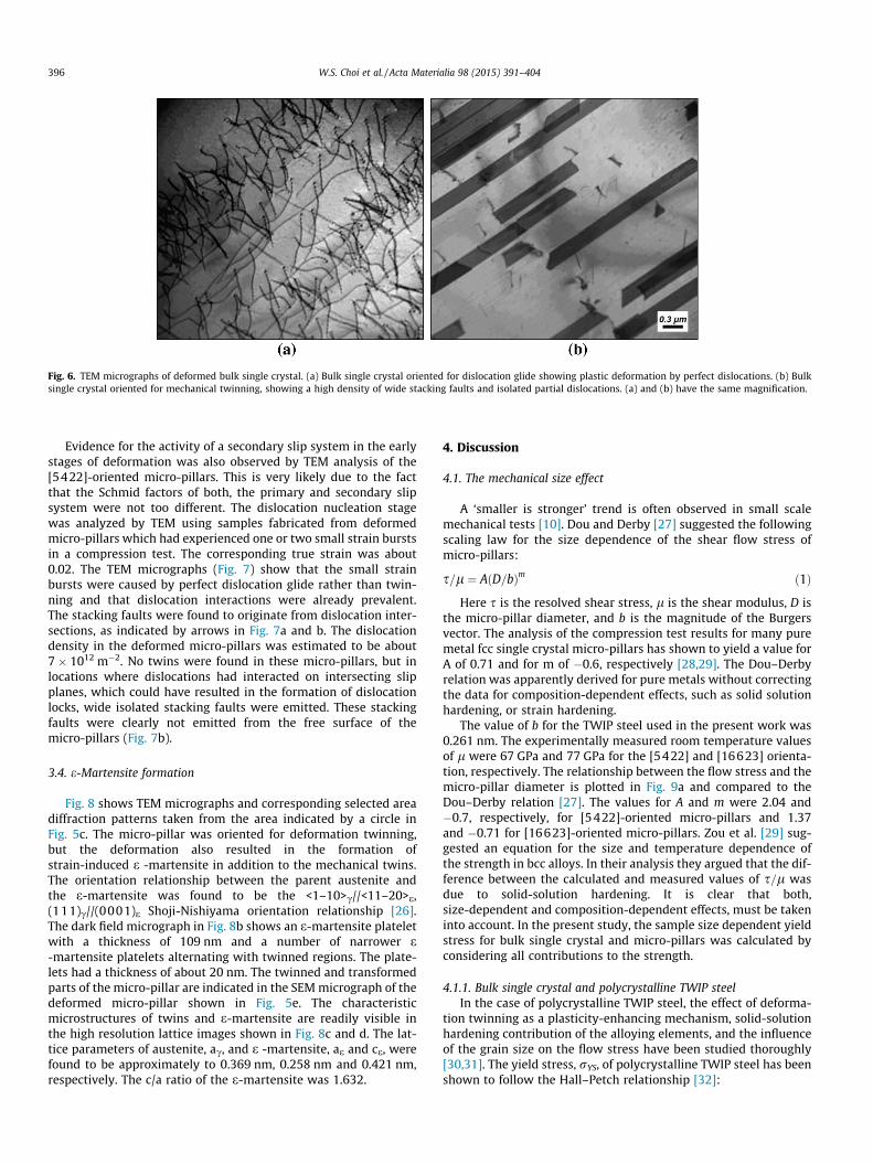
Fig. 6. TEM micrographs of deformed bulk single crystal. (a) Bulk single crystal oriented for dislocation glide showing plastic deformation by perfect dislocations. (b) Bulksingle crystal oriented for mechanical twinning, showing a high density of wide stacking faults and isolated partial dislocations. (a) and (b) have the same magnification.
396 W.S. Choi et al. / Acta Materialia 98 (2015) 391–404
Evidence for the activity of a secondary slip system in the earlystages of deformation was also observed by TEM analysis of the[5422]-oriented micro-pillars. This is very likely due to the factthat the Schmid factors of both, the primary and secondary slipsystem were not too different. The dislocation nucleation stagewas analyzed by TEM using samples fabricated from deformedmicro-pillars which had experienced one or two small strain burstsin a compression test. The corresponding true strain was about0.02. The TEM micrographs (Fig. 7) show that the small strainbursts were caused by perfect dislocation glide rather than twin-ning and that dislocation interactions were already prevalent.The stacking faults were found to originate from dislocation inter-sections, as indicated by arrows in Fig. 7a and b. The dislocationdensity in the deformed micro-pillars was estimated to be about7 � 1012 m�2. No twins were found in these micro-pillars, but inlocations where dislocations had interacted on intersecting slipplanes, which could have resulted in the formation of dislocationlocks, wide isolated stacking faults were emitted. These stackingfaults were clearly not emitted from the free surface of themicro-pillars (Fig. 7b).
3.4. e-Martensite formation
Fig. 8 shows TEM micrographs and corresponding selected areadiffraction patterns taken from the area indicated by a circle inFig. 5c. The micro-pillar was oriented for deformation twinning,but the deformation also resulted in the formation ofstrain-induced e -martensite in addition to the mechanical twins.The orientation relationship between the parent austenite andthe e-martensite was found to be the <1–10>c//<11–20>e,(111)c//(0001)e Shoji-Nishiyama orientation relationship [26].The dark field micrograph in Fig. 8b shows an e-martensite plateletwith a thickness of 109 nm and a number of narrower e-martensite platelets alternating with twinned regions. The plate-lets had a thickness of about 20 nm. The twinned and transformedparts of the micro-pillar are indicated in the SEM micrograph of thedeformed micro-pillar shown in Fig. 5e. The characteristicmicrostructures of twins and e-martensite are readily visible inthe high resolution lattice images shown in Fig. 8c and d. The lat-tice parameters of austenite, ac, and e -martensite, ae and ce, werefound to be approximately to 0.369 nm, 0.258 nm and 0.421 nm,respectively. The c/a ratio of the e-martensite was 1.632.
4. Discussion
4.1. The mechanical size effect
A ‘smaller is stronger’ trend is often observed in small scalemechanical tests [10]. Dou and Derby [27] suggested the followingscaling law for the size dependence of the shear flow stress ofmicro-pillars:
s=l ¼ AðD=bÞm ð1Þ
Here s is the resolved shear stress, l is the shear modulus, D isthe micro-pillar diameter, and b is the magnitude of the Burgersvector. The analysis of the compression test results for many puremetal fcc single crystal micro-pillars has shown to yield a value forA of 0.71 and for m of �0.6, respectively [28,29]. The Dou–Derbyrelation was apparently derived for pure metals without correctingthe data for composition-dependent effects, such as solid solutionhardening, or strain hardening.
The value of b for the TWIP steel used in the present work was0.261 nm. The experimentally measured room temperature valuesof l were 67 GPa and 77 GPa for the [5422] and [16623] orienta-tion, respectively. The relationship between the flow stress and themicro-pillar diameter is plotted in Fig. 9a and compared to theDou–Derby relation [27]. The values for A and m were 2.04 and�0.7, respectively, for [5422]-oriented micro-pillars and 1.37and �0.71 for [16623]-oriented micro-pillars. Zou et al. [29] sug-gested an equation for the size and temperature dependence ofthe strength in bcc alloys. In their analysis they argued that the dif-ference between the calculated and measured values of s=l wasdue to solid-solution hardening. It is clear that both,size-dependent and composition-dependent effects, must be takeninto account. In the present study, the sample size dependent yieldstress for bulk single crystal and micro-pillars was calculated byconsidering all contributions to the strength.
4.1.1. Bulk single crystal and polycrystalline TWIP steelIn the case of polycrystalline TWIP steel, the effect of deforma-
tion twinning as a plasticity-enhancing mechanism, solid-solutionhardening contribution of the alloying elements, and the influenceof the grain size on the flow stress have been studied thoroughly[30,31]. The yield stress, rYS, of polycrystalline TWIP steel has beenshown to follow the Hall–Petch relationship [32]:

Fig. 7. TEM micrographs of a [5422]-oriented micropillar deformed up to theobservation of a first strain burst. Bright-field micrographs ((a) g ¼ ð�1�11Þ, (b)g ¼ ð002Þ), showing long dislocation segments (A) and stacking faults emitted fromdislocation junctions (arrows). (c) Isolated wide stacking faults in the interior of themicropillar. The dislocation density of the micropillars was about 7� 1012 m�2.
W.S. Choi et al. / Acta Materialia 98 (2015) 391–404 397
rYS ¼ r0YS þ
kHPYSffiffiffidp ð2Þ
Here the parameter r0YS includes the lattice friction stress, i.e.
the solid solution strengthening contribution of the alloying ele-ments, and the strain hardening contribution of the initial disloca-
tion density, kHPYS is the dislocation un-pinning parameter at the
yield point, d is the grain size, r0YS and kHP
YS have been reported to
be equal to 132 MPa and 449 MPa lm1/2, respectively, for polycrys-talline Fe-22 wt%Mn-0.6 wt%C TWIP steel [31]. The r0
YS value givenin the original manuscript seems to be mistyped since the yieldstress level is significantly lower than the value calculated usingEq. (2) with the constants from the same reference. The value ofr0
YS was therefore re-evaluated using the yield stress values mea-sured for polycrystalline Fe-22 wt%Mn-0.6 wt%C TWIP steel. Thiscorrected value for r0
YS was determined to be 242 MPa, rather than132 MPa, as reported by Bouaziz et al. [31], and the correspondingcritical shear stress was 79 MPa, assuming a Taylor factor of 3.06.This value is similar to the value of the yield shear stress for bulksingle crystal of TWIP steel mentioned in Section 3.1.
4.1.2. Critical resolved shear stress calculationThe flow shear stress, stot, can be expressed by the sum of the
intrinsic Peierls lattice resistance to dislocation glide and addi-tional strengthening contributions:
stot ¼ sP þ ss�s þ sd þ ss ð3Þ
Here sP denotes the Peierls stress, ss�s is the solid solution hard-ening due to substitutional and interstitial alloying elements, andsd is the strengthening from dislocation–dislocation interactions.The dislocation source size-controlled term, ss, is included to takethe effect of the crystal size into account [13].
The following equation was used to obtain the temperaturedependence of the Peierls shear stress [33]:
sPðTÞlðTÞ ¼
sPð0Þlð0Þ 1� kT
g0lðTÞb3 ln
_e0
_e
� �" #1=q8<:
9=;
1=p
ð4Þ
Here, kB is the Boltzmann constant, g0 is a normalized activationenergy with a value of 0.13 [34], _e is the strain rate, _e0 is a referenceshear strain rate, which is equal to 108 s�1 [35], p and q are equal to1/2 and 3/2, respectively, lð0Þ is the shear modulus at 0 K, whichwas calculated by means of the following equation [36]:
lð0Þ ¼ lðTÞ½1� 7:9921� 10�7T2 þ 3:317� 10�10T3��1 ð6Þ
The Peierls stress for edge dislocations at 0 K, sPð0Þ; is given by[37,38]:
sedgeP ð0Þ ¼ l
1� mexp
�2p1� m
� df111g
b
� �ð7Þ
The Peierls stress for screw dislocations at 0 K, sPð0Þ; is given by[37,38]:
sscrewP ð0Þ ¼ l exp �2p � df111g
b
� �ð8Þ
The Poisson’s ratio m is equal to 0.312 [34]. The ratio of the effec-tive {111} interplanar spacing and the magnitude of the Burgers
vector, df111gb ; is equal to 1.1547, using df111g ¼
ffiffiffi6p
=3ac [35,36].The calculated sP at 297 K is 0.14 MPa and 2.64 MPa for edge andscrew dislocations, respectively, sP was set equal to the mean valueof both values, 1.39 MPa.
The solid solution hardening effect of C in Fe-22%Mn-0.6%CTWIP steel on the yield shear stress was obtained experimentallyby varying the C content of a Fe-x%C-15%Mn-2%Al-1%Si TWIP steelin the range of 0.78–0.92 wt%. The results, shown in Fig. 10, indi-cate a solid solution hardening effect on the shear stress of91.3 MPa per wt%C. The solid solution hardening effect of Mnwas taken as �0.59 MPa per wt%Mn [34]. As a result, the ss�s
was equal to 44.0 MPa for the Fe-22 wt%Mn-0.6 wt%C TWIP steel.Note that these solid solution hardening effects must be multipliedby 3.06 to obtain the solid solution strengthening effect in tensiledeformation.

Fig. 8. TEM micrographs of a deformed micropillar oriented for deformation twinning. (a) Selected area diffraction pattern indicating the presence of twins and e-martensite.(b) Dark field micrographs showing twins and e-martensite in the parent austenite matrix. High resolution micrographs of (c) twinned region and (d) e-martensite plate.
398 W.S. Choi et al. / Acta Materialia 98 (2015) 391–404
The dislocation–dislocation interactions lead to a strain harden-ing contribution sd described quantitatively by the Hirsch–Baileyequation:
sd ¼ albffiffiffiffiffiffiqdp ð9Þ
Here a is a constant and qd is the total dislocation density. Thevalue of a is 0.35. The measured dislocation density in themicro-pillar was about 7� 1012 m�2. The value of sd, obtained bymeans of Eq. (9), was therefore 15.7 MPa.
Several models have been proposed to explain the crystal sizedependence of the critical shear stress [13,39–41]. Parthasarathyet al. [13] suggested that double-ended dislocation sources inmicro-pillars could easily become single-ended dislocation sourcesby interaction with a free surface. This process should result instrengthening when testing micron-size samples such asmicro-pillars. The strength of single-ended and double-endedsources in small crystals calculated by discrete dislocation dynam-ics simulations, support the following type of dislocation sourcesize dependence [14]:
ss ¼ KlbL
lnLb
� �ð10Þ
Here K is a source-hardening constant, which is 0.12 for asingle-ended dislocation source. The calculated effect of imageforces on the critical resolved shear stress for dislocation sourceslarger than 250b has been shown to be negligible [14].
The following dislocation segment length dependence of theline tension stress was included in the model for the shear stressacting on a dislocation segment of length L [42]:
ss ¼lbL
12pð1� vÞ 1� 3
2v
� �ln
Lb
� �þ v � 2
2
� �ð11Þ
Eqs. (4) to Eq. (10) were combined to obtain the following equa-tion for stot:
stotl ¼
sPð0Þlð0Þ 1� kT
g0lðTÞb3 ln _e0
_e
� �h i1=q 1=p
þ ss�sl þ ab
ffiffiffiffiffiffiqdp
þ bL
12pð1�vÞ 1� 3
2 v� �
ln Lb
� �þ v�2
2
� ð12Þ
Norfleet et al. [40] reported that the model containing mea-sured dislocation density and size-dependent source strengtheningwas not sufficient to explain the observed yield stress ofmicro-pillars. Zou et al. [29] used a higher value of 0.5 for K, assum-ing that the dislocation source length was limited by the diameterof the micro-pillar. The correct micro-pillar diameter dependenceof the effective source length, Leff, can, however, be obtained bycombining Eqs. (1) and (12):
lbLeff
12pð1� vÞ 1� 3
2v
� �ln
Leff
b
� �þ v � 2
2
� �
¼ AlðD=bÞm � ðsP þ ss�s þ sdÞ ð13Þ
Fig. 11 shows the size dependence of Leff. The value of Leff
increases asymptotically for a micro-pillar with a critical diameter.With decreasing pillar size, the dislocation source size must neces-sarily become smaller and the ratio of the effective source lengthand the micro-pillar diameter, Leff/D, decreases. Eq. (13) also allowsfor the determination of the critical pillar size for bulk behavior.The critical diameter is about 7.6 lm where the effective source
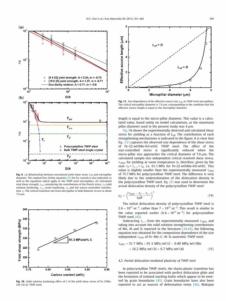
Fig. 9. (a) Relationship between normalized yield shear stress s/l and micropillardiameter. The original Dou–Derby equation [25] for fcc crystals is also indicated, aswell as the equations which apply to the TWIP steel micropillars. (b) Calculatedtotal shear strength, stot, considering the contributions of the Peierls stress, sP, solidsolution hardening, ss-s, strain hardening, sd, and the source-controlled contribu-tion, ss. The critical transition size from micropillar to bulk behavior occurs at about7.6 lm.
Fig. 10. Solid solution hardening effect of C of the yield shear stress of Fe-15Mn-2Al-1Si-xC TWIP steel.
Fig. 11. Size dependence of the effective source size, Leff, in TWIP steel micropillars.The critical micropillar diameter is 7.6 lm, corresponding to the condition that theeffective source length is equal to the micropillar diameter.
W.S. Choi et al. / Acta Materialia 98 (2015) 391–404 399
length is equal to the micro-pillar diameter. This value is a calcu-lated value, based solely on model calculations, as the maximumpillar diameter used in the present study was 4 lm.
Fig. 9b shows the experimentally observed and calculated shearstress for yielding as a function of Leff. The contribution of eachstrengthening mechanisms is indicated in the figure. It is clear thatEq. (12) captures the observed size dependence of the shear stressof Fe-22 wt%Mn-0.6 wt%C TWIP steel. The effect of thesize-controlled stress is significantly reduced when themicro-pillar size approaches the critical diameter of 7.6 lm. Thecalculated sample-size independent critical resolved shear stress,sCRSS, for yielding at room temperature is, therefore, given by thesum sP + ss�s + sd, i.e. 61.1 MPa for Fe-22 wt%Mn-0.6 wt%C. Thisvalue is slightly smaller than the experimentally measured sCRSS
of 75.7 MPa for polycrystalline TWIP steel. The difference is verylikely due to the underestimation of the dislocation density inthe polycrystalline TWIP steel. Eq. (9) was used to determine theactual dislocation density of the polycrystalline TWIP steel:
qd ¼sCRSS � sP � ss�s
alb
� �2
ð14Þ
The initial dislocation density of polycrystalline TWIP steel is2:6� 1013 m�2, rather than 7� 1012 m�2. This result is similar tothe value reported earlier (6:4� 1013 m�2) for polycrystallineTWIP steel [43].
Subtracting ss�s from the experimentally measured sCRSS, andtaking into account the solid solution strengthening contributionsof Mn, Al and Si reported in the literature [34,44], the followingequation was obtained for the composition dependence of the sizeindependent sCRSS of Fe–Mn–C–Al–Si austenitic TWIP steel:
sCRSS ¼ 31:7 MPaþ 91:3 MPa=wt%C� 0:49 MPa=wt%Mn
þ 16:2 MPa=wt%Siþ 6:7 MPa=wt%Al ð15Þ
4.2. Partial dislocation-mediated plasticity of TWIP steel
In polycrystalline TWIP steels, the elasto-plastic transition hasbeen reported to be associated with perfect dislocation glide andthe formation of isolated stacking faults which appear to be emit-ted by grain boundaries [45]. Grain boundaries have also beenreported to act as sources of deformation twins [46]. Mahajan

400 W.S. Choi et al. / Acta Materialia 98 (2015) 391–404
and Chin [47] suggested that twin nuclei, formed by three stackingfaults on adjacent {111} planes, could grow into twins by a collec-tive bow-out mechanism between pinning points. Deformationtwinning may also occur after dislocation–dislocation interactionswhich result in configurations, such as suitably oriented sessilejogs of screw-type dislocations, which can act as twin sources bya pole mechanism [48]. Experimental observations by TEM suggestthat twin nucleation, due to the operation of the pole mechanism,occurs in the early stages of deformation [49]. In the course of thepresent work, TEM analysis of pillars compressed up to the obser-vation of the first strain burst was carried out, and no deformationtwins or strain-induced e-martensite plates were observed.
4.2.1. Elasto-plastic transitionDuring the elasto-plastic transition, dislocation sources become
active. The maximum dislocation source length in a micro-pillar islimited by the pillar size. Single-ended dislocation sources havebeen reported to be the dominant dislocation sources in themicro-pillars [13] and in thin TEM foils which were strained inthe microscope [50]. The size of a single-ended dislocation wasmuch smaller than the size of a double-pinned Frank-Read source,which was in the range of 160–500 nm in in-situ strained TEMsamples [50]. Dislocations nucleated from a single-ended sourcecan easily escape out of a micro-pillar during deformation withoutdislocation pile-up formation or interactions leading to sessile dis-location junctions [50]. Greer et al. [12] suggested that the mini-mum travel distance required for dislocation multiplication wasof the order of 1 lm in Ag. They reported that micro-pillars witha diameter smaller than 0.7 lm had a higher flow stress thanexpected from a general power law. They argued that this wasdue to dislocation starvation occurring before dislocation
Fig. 12. Dislocation loop size dependence of the nucleation energy of a partial dislocatiodiameter of (a) 4 lm, (b) 2 lm, (c) 1 lm, and (d) 0.6 lm. The experimentally measured cridea of the relative dimensions of the micropillars.
multiplication. Here, evidence of dislocation–dislocation interac-tions in the initial stage of deformation was obtained from TEManalysis of micro-pillars which had been strained until the firstand second strain burst was observed. These strain bursts weredue to dislocation sources, which rapidly produced avalanches ofmobile dislocations.
The energy for the activation of a perfect dislocation Frank-Readsource and a partial dislocation twin source can be computed asthe energy required to nucleate a perfect dislocation loop, Eperfect,and a partial dislocation loop, Etwin, respectively [42]:
Eperfect ¼ �pR2sbþ 12lb2R
2� m2ð1� mÞ ln
4Rr� 2
� �ð16Þ
and
Etwin ¼ �pR2sbp þ12lb2R
2� m2ð1� mÞ ln
4Rr� 2
� �þ pR2cSF ð17Þ
Here q is the core radius of the dislocation, which is assumed tobe equal to the Burgers vector and R is a dislocation loop radius.Fig. 12 shows the dislocation loop size dependence of the activa-tion energy of dislocation loops for the measured average yieldshear stresses of micro-pillars with different diameters. The curvesshow that the energy barrier for source activation reaches a max-imum at the critical stress. The maximum energy barrier occursat a critical dislocation loop size corresponding to the condition@E=@RjR¼Rc
¼ 0. Fig. 13a and b show the applied shear stress depen-dence of the critical dislocation loop size and critical nucleationenergy. The figure also indicates the average critical resolved shearstress measured for the micro-pillars in this work. The difference incritical loop size at an applied shear stress smaller than 200 MPa
n twin source and of a perfect dislocation Frank-Read source for micropillars with aitical shear stress is indicated for each of the calculated curves. The cylinders give an

Fig. 13. Applied shear stress dependence of (a) the critical size with the effectivesource size, Leff, and (b) the critical energy of nucleation of a partial dislocation halfloop and a perfect dislocation half loop. The partial dislocation loop is unstable at anapplied shear stress lower than 150 MPa. The vertical lines indicate the appliedshear stress required to reach the point of dislocation half loop instability for themicropillar diameters used in the present work.
Fig. 14. Applied shear stress dependence of the effective stacking fault energy for a[5422]-oriented pillar deformed in compression. The vertical lines indicate themean shear stress of large strain bursts for the micropillars with the indicateddiameter. The shear yield stress of the bulk single crystal (Xtal) is also indicated. Theeffective stacking fault energy decreases with decreasing micropillar diameter,resulting in strain-induced c ? e transformation in condition where the equilib-rium SFE is about 23 mJ/m2.
W.S. Choi et al. / Acta Materialia 98 (2015) 391–404 401
increased exponentially, resulting in the divergence of the criticalloop size at an applied shear stress of about 150 MPa. It is notablethat Leff obtained from Eq. (13) was in accordance with the calcu-lated critical size for a perfect dislocation loop. A similar trendwas shown for the critical energy of nucleation. As the appliedshear stress increased due to the size effect, the critical size andenergy of nucleation of partial and perfect dislocation loopsbecame comparable. The critical shear stress for yielding of[011]-oriented and [001]-oriented bulk single crystal was76 MPa and 72 MPa, respectively. It is thus unlikely that a partialdislocation source was activated at such low stresses, since a par-tial dislocation source cannot achieve instability and expand atsuch a low stress level. In addition, the critical resolved shear stres-ses for yielding of [5422]- and [16623]-oriented micro-pillarswere similar as shown in Fig. 4. The calculation and the experimen-tal observation imply that the elasto-plastic transition in themicro-pillars and the bulk single crystals oriented for twinning isachieved by a dislocation mechanism that does not involvetwinning.
4.2.2. Mechanisms for twinning and e-martensite formationThe deformation mechanisms of polycrystalline TWIP steel with
various SFE were experimentally determined by Allain et al. andc ? e-martensite transformation was only observed in
Fe-22 wt%Mn-0.6 wt%C TWIP steel deformed at 77 K [51]. In thepresent study, the strain-induced c ? e transformation was, how-ever, observed during micro-pillar compression at room tempera-ture. This observation can be understood by consideration of theapplied shear stress dependence of the effective SFE, ceff. ceff isdefined as follows [21,22]:
ceff ¼ c0 þmt �ml
2sAb ð18Þ
Here c0 is the equilibrium SFE in the absence of an appliedstress, mt and ml are the Schmid factor of the trailing and leadingpartial dislocations, respectively, and sA is the applied shear stress.The applied shear stress dependence of ceff and the stress at whichlarge strain bursts were experimentally observed are indicated inFig. 14. ceff could clearly be reduced to a value much lower thanthe value of the SFE required for the c ? e transformation in highstress conditions. This implies that the c ? e transformationbecame energetically favorable in micro-pillars oriented for partialdislocation glide in compression tests. As the applied stressincreased, the stacking fault width increased substantially, allow-ing the strain-induced c ? e phase transformation to occur [52].
Fig. 15 shows a schematic of the deformed micro-pillars. Themechanisms which explain the observed deformation twinningand dislocation glide in the micro-pillars are also indicated. Thesmall cube in the figure corresponds to the unit cell orientationin the [16 6 23]-oriented and [5 4 22]-oriented micro-pillar. Theprimary slip system is enlarged to make the dislocation configura-tion clear. In order to generate perfect dislocations, it is proposedthat screw segments of the primary slip system could easilycross-slip twice due to the reduced stacking fault width, which alsoresulted in the observed wave-like slip traces shown in Fig. 5f.Once double cross-slip had occurred, Frank-Read type dislocationsources were generated as shown in Fig. 15a [42] and easilybecame single-ended dislocation sources due to the size of themicro-pillar [13]. The successive generation of perfect dislocationloops from a single dislocation source also explains why the sheardeformation of micro-pillars oriented for perfect dislocation glidewas highly localized (Fig. 5d).
In the case of micro-pillars oriented for twinning, it is postu-lated that a screw type pole dislocation allowed for the formation
Fig. 15. Schematic of the deformation mechanisms in micropillars oriented for (a) dislocation glide and (b) deformation twinning. In (a) the localized deformation is due tothe activation of a Frank-Read dislocation source formed by the double cross-slip mechanism. Double cross-slip is preferential due to the high effective SFE. In (b) theformation of a mechanical twin and/or an e-martensite platelet is by the screw dislocation pole mechanism. The formation of the e-martensite plate is due to a double polemechanism.
402 W.S. Choi et al. / Acta Materialia 98 (2015) 391–404
of a twin by spiraling of the dC twinning partial dislocation aroundthe CD screw type pole dislocation segments on either side of thejog, as shown in Fig. 15b [42,51]. If two screw dislocations wereacting as pole dislocation instead of one, the partial dislocationdC would glide on every second slip plane (Fig. 15b) and this couldresult in the formation of e-martensite. The mechanism is astraightforward extension of the twinning formation mechanismproposed by Niewczas and Saada [53]. No geometrical difficultyexists to grow e-martensite by a similar pole mechanism exceptfor the stress barrier associated with the Frank dislocation.Double-pole dislocation configurations have been observed exper-imentally by TEM [53]. The e-martensite formation mechanism isshown in detail in Fig. 16. The indicated dislocations correspondto those for the [5422]-oriented micro-pillar. The figure showstwo segments of a primary pole dislocation with a Burgers vectorCD connected by two nodes N1 and N2. An additional pole disloca-tion with the same Burgers vector, adjacent to the primary poledislocations, allow for the partial dislocation dC to glide on everysecond slip plane, resulting in the formation of an e-martensiteplatelet.
In this model it was assumed that the nature of the stackingfault was intrinsic. The available reports on the analysis of the nat-ure of stacking faults in high Mn austenitic steels analysis disagree.Whereas Idrissi et al. [49] report that the stacking faults are extrin-sic, based on their analysis of stacking fault fringe contrast, Pierceet al. [54], using conventional diffraction contrast, more recentlyconcluded that the stacking faults were intrinsic. Furthermore,
we observed only intrinsic stacking faults in the present studyand, therefore, did not further consider extrinsic stacking faultsas nuclei for e-martensite formation.
Using the high resolution SEM (Fig. 5) and TEM (Fig. 7) micro-graphs, the strain contributed by mechanical twinning andstrain-induced e-martensite formation was determined. InFig. 15b, the total thickness, t, of the twinned region ande-martensite plate was 1139 nm in the micro-pillar at a total trueplastic strain of 0.18. The angle between the matrix and the trans-formed plane was 42�. Partial dislocations glide on every slip planein the case of a twin and on every second slip plane in the case of ae-martensite platelet. The corresponding amount of deformationwas 0.07 true strain. The remaining plastic strain of about 0.10must have been contributed by dislocation glide and dislocationavalanches, which were visible as sharp slip traces in the deformedmicro-pillars. In the case of the [5422]-oriented micro-pillars, thesecondary slip system has probably been activated at a low stresslevel, since the Schmid factor for the secondary slip plane was closeto the Schmid factor of the primary slip system. This resulted in thedislocation intersections shown in the TEM micrograph ofFig. 7a and b. It is postulated that in the present case these struc-tural defects acted as source for the dislocations required for themechanisms shown in Fig. 15. Another possibility is that theinelastic Ga+ ion–solid interactions within the sample, occurringduring the FIB sample preparation may have resulted in the forma-tion of dislocation loops. Such inelastic Ga+ ion–solid interactionsare known to cause lattice damage and introduce point defects
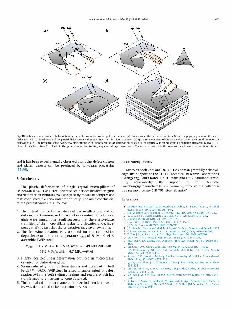
Fig. 16. Schematic of e-martensite formation by a double screw dislocation pole mechanism. (a) Nucleation of the partial dislocation Cd on a large jog segment on the screwdislocation CD. (b) Break-away of the partial dislocation Cd after reaching its critical loop diameter. (c) Spiraling movement of the partial dislocation Cd around the two poledislocations. (d) The presence of the two screw dislocations with Burgers vector CD acting as poles, causes the partial Cd to spiral around, and being displaced by two {111}planes for each rotation. This leads to the generation of the stacking sequence of hcp e-martensite. The e-martensite plate thickens with each partial dislocation rotation.
W.S. Choi et al. / Acta Materialia 98 (2015) 391–404 403
and it has been experimentally observed that point defect clustersand planar defects can be produced by ion-beam processing[55,56].
5. Conclusions
The plastic deformation of single crystal micro-pillars ofFe-22%Mn-0.6%C TWIP steel oriented for perfect dislocation glideand deformation twinning was analyzed by means of compressiontests conducted in a nano-indentation setup. The main conclusionsof the present work are as follows:
1. The critical resolved shear stress of micro-pillars oriented fordeformation twinning and micro-pillars oriented for dislocationglide were similar. The result suggests that the elasto-plastictransition of the micro-pillars is due to dislocation glide, inde-pendent of the fact that the orientation may favor twinning.
2. The following equation was obtained for the compositiondependence of the room temperature sCRSS of Fe–Mn–C–Al–Siaustenitic TWIP steel:
sCRSS ¼ 31:7 MPaþ 91:3 MPa=wt%C� 0:49 MPa=wt%Mn
þ 16:2 MPa=wt%Siþ 6:7 MPa=wt%Al
3. Highly localized shear deformation occurred in micro-pillarsoriented for dislocation glide.
4. Strain-induced c ? e transformation is not observed in bulkFe-22%Mn-0.6%C TWIP steel. In micro-pillars oriented for defor-mation twinning both twinned regions and regions which hadtransformed to e-martensite were observed.
5. The critical micro-pillar diameter for size-independent plastic-ity was determined to be approximately 7.6 lm.
Acknowledgements
Mr. Won Seok Choi and Dr. B.C. De Cooman gratefully acknowl-edge the support of the POSCO Technical Research Laboratories,Gwangyang, South Korea. Dr. D. Raabe and Dr. S. Sandlöbes grate-fully acknowledge the support of the DeutscheForschungsgemeinschaft (DFG), Germany, through the collabora-tive research centre SFB 761 ‘Steel ab initio’.
References
[1] M. Niewczas, Chapter 75, Dislocations in Solids, in: F.R.N. Nabarro, J.P. Hirth(Eds.), Elsevier BV, 2007, pp. 264–364.
[2] S.R. Kalidindi, A.A. Salem, R.D. Doherty, Adv. Eng. Mater. 5 (2003) 229–232.[3] O. Bouaziz, N. Guelton, Mater. Sci. Eng. A 319–321 (2001) 246–249.[4] S. Mahajan, Philos. Mag. 23 (1971) 781–794.[5] C.W. Price, J.P. Hirth, Mater. Sci. Eng. 9 (1972) 15–18.[6] J.C.M. Li, Trans. AIME 227 (1963) 239–247.[7] J.F. Nicholas, An Atlas of Models of Crystal Surfaces, Gordon and Breach, 1965.[8] C.R. Weinberger, W. Cai, Proc. Natl. Acad. Sci. 105 (2008) 14304–14307.[9] T. Zhu, J. Li, A. Samanta, K. Gall, Phys. Rev. Lett. 100 (2008) 025502.
[10] J.R. Greer, J.T.M. Hosson, Prog. Mater. Sci. 56 (2011) 654–724.[11] M.D. Uchic, P.A. Shade, D.M. Dimiduk, Annu. Rev. Mater. Res. 39 (2009) 361–
386.[12] J.R. Greer, W.C. Oliver, W.D. Nix, Acta Mater. 53 (2005) 1821–1830.[13] T.A. Parthasarathy, S.I. Rao, D.M. Dimiduk, M.D. Uchic, D.R. Trinkle, Scripta
Mater. 56 (2007) 313–316.[14] S.I. Rao, D.M. Dimiduk, M. Tang, T.A. Parthasarathy, M.D. Uchic, C. Woodward,
Philos. Mag. 87 (2007) 4777–4794.[15] Q. Yu, Z.-W. Shan, J. Li, X. Huang, L. Xiao, J. Sun, E. Ma, Nat. Lett. 463 (2010)
335–338.[16] J.H. Seo, H.S. Park, Y. Yoo, T.Y. Seong, J. Li, J.P. Ahn, B. Kim, I.S. Choi, Nano Lett.
13 (2013) 5112–5116.[17] S.Z. Wu, H.W. Yen, M.X. Huang, A.H.W. Ngan, Scripta Mater. 67 (2012) 641–
644.[18] S. Reeh, D. Music, T. Gebhardt, M. Kasprzak, T. Jäpel, S. Zaefferer, D. Raabe, S.
Richter, A. Schwedt, J. Mayer, B. Wietbrock, G. Hirt, J.M. Schneider, Acta Mater.60 (2012) 6025–6032.
404 W.S. Choi et al. / Acta Materialia 98 (2015) 391–404
[19] I. Gutierrez-Urrutia, D. Raabe, Acta Mater. 59 (2011) 6449–6462.[20] A. Dumay, J.P. Chateau, S. Allain, S. Migot, O. Bouaziz, Mater. Sci. Eng. A 483–
484 (2008) 184–187.[21] S.M. Copley, B.H. Kear, Acta Metall. 16 (1968) 227–231.[22] I. Karaman, H. Sehitoglu, K. Gall, Y.I. Chumlyakov, H.J. Maier, Acta Mater. 48
(2000) 1345–1359.[23] D.M. Dimiduk, C. Woodward, R. LeSar, M.D. Uchic, Science 312 (2006) 1188–
1190.[24] A. Rinaldi, P. Peralta, C. Friesen, K. Sieradzki, Acta Mater. 56 (2008) 511–517.[25] F. Mompiou, M. Legros, A. Sedlmayr, D.S. Gianola, D. Caillard, O. Kraft, Acta
Mater. 60 (2012) 977–983.[26] J.B. Seol, J.E. Jung, Y.W. Jang, C.G. Park, Acta Mater. 64 (2013) 558–578.[27] R. Dou, B. Derby, Scripta Mater. 61 (2009) 524–527.[28] M.J. Burek, J.R. Greer, Nano Lett. 10 (2009) 69–76.[29] Y. Zou, S. Maiti, W. Steurer, R. Spolenak, Acta Mater. 65 (2014) 85–97.[30] B.C. Cooman, O. Kwon, K.-G. Chin, Mater. Sci. Technol. 28 (2012) 513–527.[31] O. Bouaziz, S. Allain, C.P. Scott, P. Cugy, D. Barbier, Curr. Opin. Solid State
Mater. Sci. 15 (2011) 141–168.[32] B.C. Cooman, J.G. Speer, Fundamentals of Steel Product Physical Metallurgy,
third ed., AIST, Warrendale, PA, 2012.[33] P.S. Follansbee, Fundamentals of Strength, John Wiley & Sons Inc., 2014.[34] I. Jung, B.C. Cooman, Acta Mater. 61 (2013) 6724–6735.[35] N. Tsuchida, Y. Tomota, H. Moriya, O. Umezawa, K. Nagai, Acta Mater. 29
(2001) 3029–3038.[36] G. Ghosh, G.B. Olson, Acta Mater. 50 (2002) 2655–2675.[37] J.N. Wang, Mater. Sci. Eng. A 206 (1996) 259–269.
[38] J.N. Wang, Acta Mater. 4 (1996) 1541–1546.[39] K.S. Ng, A.H.W. Ngan, Scripta Mater. 59 (2008) 796–799.[40] D.M. Norfleet, D.M. Dimiduk, S.J. Polasik, M.D. Uchic, M.J. Mills, Acta Mater. 56
(2008) 2988–3001.[41] S.W. Lee, W.D. Nix, Philos. Mag. 92 (2012) 1238–1260.[42] J.P. Hirth, J. Lothe, Theory of Dislocations, second ed., John Wiley & Sons, Inc.,
1992.[43] J. Kim, Y. Estrin, H. Beladi, I. Timokhina, K.G. Chin, S.K. Kim, B.C. De Cooman,
Metall. Mater. Trans. A 66 (2012) 479–490.[44] K. Jeong, J.E. Jin, Y.S. Jung, S. Kang, Y.K. Lee, Acta Mater. 61 (2013) 3399–3410.[45] D.R. Steinmetz, T. Jäpel, B. Wietbrock, P. Eisenlohr, I. Gutierrez-Urrutia, A.
Saeed-Akbari, T. Hickel, F. Roters, D. Raabe, Acta Mater. 61 (2013) 494–510.[46] Z. Jin, T.R. Bieler, Philos. Mag. A 71 (1995) 925–947.[47] S. Mahajan, G.Y. Chin, Acta. Metall. 21 (1973) 1353–1363.[48] J.A. Venables, Philos. Mag. 6 (1960) 379–396.[49] H. Idrissi, K. Renard, L. Ryelandt, D. Schryvers, P.J. Jacques, Acta. Mater. 58
(2010) 2464–2476.[50] S.H. Oh, M. Legros, D. Kiener, G. Dehm, Nat. Mater. 8 (2009) 95–100.[51] S. Allain, J.-P. Chateau, O. Bouaziz, S. Migot, N. Guelton, Mater. Sci. Eng. A 387–
389 (2004) 158–162.[52] T.S. Byun, Acta Mater. 51 (2003) 3063–3071.[53] M. Niewczas, G. Saada, Philos. Mag. A 82 (2002) 167–191.[54] D.T. Pierce, J.A. Jimenez, J. Bentley, D. Raabe, C. Oskay, J.E. Wittig, Acta Mater.
68 (2014) 238–253.[55] C.A. Volkert, A.M. Minor, MRS Bull. 32 (2007) 389–395.[56] S.O. Kucheyev, J.S. Williams, C. Jagadish, J. Zou, Phys. Rev. B 67 (2003) 094115.
Copyright © 2022 FDOKUMEN