Evolution of dislocation mechanisms in single-crystal Cu ...
19
This content has been downloaded from IOPscience. Please scroll down to see the full text. Download details: IP Address: 203.110.242.6 This content was downloaded on 12/02/2017 at 13:43 Please note that terms and conditions apply. Evolution of dislocation mechanisms in single-crystal Cu under shock loading in different directions View the table of contents for this issue, or go to the journal homepage for more 2017 Modelling Simul. Mater. Sci. Eng. 25 025013 (http://iopscience.iop.org/0965-0393/25/2/025013) Home Search Collections Journals About Contact us My IOPscience You may also be interested in: A physically based constitutive model for FCC single crystals with a single state variable per slip system Eralp Demir Effects of orientation and vacancy defects on the shock Hugoniot behavior and spallation of single-crystal copper Enqiang Lin, Huiji Shi and Lisha Niu Dislocations and stacking faults J W Christian and V Vítek Mechanisms of anisotropic friction in nanotwinned Cu revealed by atomistic simulations J J Zhang, A Hartmaier, Y J Wei et al. Determining Burgers vectors and geometrically necessary dislocation densities from atomistic data Jun Hua and Alexander Hartmaier Nanoindentation of hcp metals: a comparative simulation study of the evolution of dislocation networks Iyad Alabd Alhafez, Carlos J Ruestes, Yu Gao et al. The importance of cross-slip in high-rate deformation Z Q Wang, I J Beyerlein and R LeSar Modeling of abnormal mechanical properties of nickel-based single crystal superalloy by three-dimensional discrete dislocation dynamics Hui Yang, Zhenhuan Li and Minsheng Huang
-
Upload
khangminh22 -
Category
Documents
-
view
0 -
download
0
Transcript of Evolution of dislocation mechanisms in single-crystal Cu ...

This content has been downloaded from IOPscience. Please scroll down to see the full text.
Download details:
IP Address: 203.110.242.6
This content was downloaded on 12/02/2017 at 13:43
Please note that terms and conditions apply.
Evolution of dislocation mechanisms in single-crystal Cu under shock loading in different
directions
View the table of contents for this issue, or go to the journal homepage for more
2017 Modelling Simul. Mater. Sci. Eng. 25 025013
(http://iopscience.iop.org/0965-0393/25/2/025013)
Home Search Collections Journals About Contact us My IOPscience
You may also be interested in:
A physically based constitutive model for FCC single crystals with a single state variable per slip
system
Eralp Demir
Effects of orientation and vacancy defects on the shock Hugoniot behavior and spallation of
single-crystal copper
Enqiang Lin, Huiji Shi and Lisha Niu
Dislocations and stacking faults
J W Christian and V Vítek
Mechanisms of anisotropic friction in nanotwinned Cu revealed by atomistic simulations
J J Zhang, A Hartmaier, Y J Wei et al.
Determining Burgers vectors and geometrically necessary dislocation densities from atomistic data
Jun Hua and Alexander Hartmaier
Nanoindentation of hcp metals: a comparative simulation study of the evolution of dislocation
networks
Iyad Alabd Alhafez, Carlos J Ruestes, Yu Gao et al.
The importance of cross-slip in high-rate deformation
Z Q Wang, I J Beyerlein and R LeSar
Modeling of abnormal mechanical properties of nickel-based single crystal superalloy by
three-dimensional discrete dislocation dynamics
Hui Yang, Zhenhuan Li and Minsheng Huang

Evolution of dislocation mechanisms insingle-crystal Cu under shock loading indifferent directions
Anupam Neogi1 and Nilanjan Mitra2,3
1 Advanced Technology Development Centre, Indian Institute of TechnologyKharagpur, Kharagpur 721302, India2 Centre for Theoretical Studies, Indian Institute of Technology Kharagpur, Kharagpur721302, India
E-mail: [email protected] and [email protected]
Received 12 August 2016, revised 4 January 2017Accepted for publication 10 January 2017Published 24 January 2017
AbstractEven though there are numerous experiments and molecular dynamic simu-lations of Cu under shock loading, there appears to be no literature on theevolution of different types of dislocation mechanisms and their mutualinteractions during the process of shock loading, which this article addressesthrough molecular dynamic simulations using the Mishin EAM potential forCu. Three different directions 100⟨ ⟩, 110⟨ ⟩, and 111⟨ ⟩ that have been con-sidered in this article are subjected to shock compression with piston velocitiesranging between 0.3–3 km s−1. The evolution of Hirth locks, Lomer–Cottrelllocks, cross-slips, jogs, and dislocation-originated stacking-fault tetrahedra aredemonstrated in this article for different direction shock loading of single-crystal Cu.
Keywords: dislocation, crystal orientation, molecular dynamics
(Some figures may appear in colour only in the online journal)
1. Introduction
Single-crystal Cu under different types of loading conditions has been studied by numerousresearchers both experimentally as well as numerically through molecular dynamics inves-tigations. In spite of that, the dislocation dynamics of Cu under shock loading beyond theHugoniot elastic limit (HEL) in different directions with regards to the temporal evolution of
Modelling and Simulation in Materials Science and Engineering
Modelling Simul. Mater. Sci. Eng. 25 (2017) 025013 (18pp) doi:10.1088/1361-651X/aa5850
3 Author to whom any correspondence should be addressed.
0965-0393/17/025013+18$33.00 © 2017 IOP Publishing Ltd Printed in the UK 1

different dislocation mechanisms and their mutual interactions has not yet been elucidatedcomprehensively, which this article aims to address.
Experimental observations of different dislocation microstructures in a recovered spe-cimen, which had been shocked using laser-ablation ultrafast pulses/shock guns, have beenreported in several literature [1–7] publications. The experimental investigations are able toprovide an observation of the final state (dislocation microstructure) of the recovered sample.However, it is unable to provide the evolution mechanism associated with the final-stateobservations of residual microstructures. Experimental observations also demonstrate anenhancement of dislocation density with shock pressure [8–10] without characterizing thetypes of dislocations and their interactions. The main objective of this article is to numerically(through molecular dynamics (MD) simulations) demonstrate the evolution of different dis-location mechanisms and their interactions leading to the final residual state experimentalobservations of dislocation microstructure.
Results obtained from large-scale molecular dynamics simulations of shock-loaded Cuhave been reported by researchers at Los Alamos National Labs [11]. It has been reported[12] that shock waves along the 100⟨ ⟩ direction form stacking faults (SFs) by slippage alongthe {111} close-packed planes, the mean spacing of which decreases with increasing value ofpiston velocity. For shock loading along the 111⟨ ⟩ direction, three slip planes with nonzeroresolved shear stress activate, resulting in the formation of a triangular pattern on the [111]surface [12]. Whereas for shock loading along the 110⟨ ⟩ direction, a complicated pattern oflocalized slippage along all four {111} planes is observed [12]. Details regarding the for-mation of different dislocation mechanisms and their interactions have not been demonstratedin the above-mentioned literature. The nucleation mechanism of dislocation loops responsiblefor plastic flow in the 100⟨ ⟩ direction has been identified in the literature [13]. The above-mentioned study contains information only with relation to the high-symmetry 100⟨ ⟩ directionand not with any other low-symmetry directions. Moreover, the above-cited work onlyidentifies the formation of dislocation loops just behind the shock front, but details of thecharacterization of the post-shock interactions of the shock-induced dislocations and asso-ciated temporal evolution have not been addressed in the work [13], which the current articlestrives to address. Most recently, Sichani et al [14] has studied dislocation density generationand plastic relaxation for the [100], [110], [111], and [321] orientation of single-crystal Cu,and Mackenchery et al [15] has investigated the dislocation evolution of the [100] single-crystal Cu. This present work aims to explore the directional dependency over the dynamicevolution of dislocation reactions more precisely, and the associated generation of shock-induced defects from a mechanistic perspective, which has not been discussed in the above-cited works.
Apart from the studies by the Los Alamos researchers, one study exists [16] usingmesoscale-continuum simulations (using finite-element-based discrete dislocation models) inwhich plasticity mechanisms for high-strain-rate loading along different directions (namely,100⟨ ⟩, 110⟨ ⟩, and 111⟨ ⟩) have been explained, based upon total dislocation density (which hasbeen matched with an analytical model [5] and experimental data [17]). It should be notedthat no effort has been made with regards to identifying the different competing dislocationmechanisms, their dissociations, and reactions involved during the process of shock loading,which this article aims to address. Thereby, this article aims to improve the understanding ofthe underlying physics behind the uniaxial shock-compression-induced plasticity of fcc sin-gle-crystal metal.
Modelling Simul. Mater. Sci. Eng. 25 (2017) 025013 A Neogi and N Mitra
2
2. Simulation methodologies
Non-equilibrium molecular dynamics (NEMD) simulation using embedded atom method(EAM) potential (developed by Mishin et al [18]) has been carried out to investigate theshock response of perfect monocrystalline Cu with orientations [100], [110], and [111]. Initialconfigurations of pure single crystal with desired orientations have been created and equili-brated by applying isothermal isobaric, NPT ensemble integration scheme (for 100 ps withtimestep size of 1 fs) along with the Nosé–Hoover thermostat algorithm at ambient temp-erature and pressure conditions. Periodic boundary conditions are maintained in all threeorthogonal directions during the equilibration period. The details of the samples, includingcrystallographic orientation, the sample dimensions, and total number of atoms, have beengiven in table 1. The simulation box size has been chosen carefully, based on prior literature[11], for ensuring the elimination of any artifact of transverse periodic boundary over theshock-induced plasticity mechanisms. The simulation domain size for this study is adequateenough to contain the entire shock in transverse directions and also the shocks are steady innature in each simulation with a rise time of ∼0.51–1.1 ps for the range of piston velocities of3.0–1.0 km s−1, respectively, for all above-mentioned crystal orientations. Even though theshock rise time, as observed in shock experiments (order of nanosecond), are much higherthan the rise time observed in a typical NEMD (order of few picosecond) shock simulation[36, 37], the essential generality of the physics behind the shock-induced deformationmechanisms are unaltered and are in good agreement with the experiments [36].
The accuracy of an MD simulation depends upon the force potential. The EAM potentialfor Cu developed by Mishin et al [18] has been chosen for this study. It should be noted thatthe EAM-Mishin potential for Cu has been developed based on ab initio and tight-bindingmethods, and is well accepted by the research community as the standard for simulations ofCu both at ambient temperature and pressure conditions and also at high-pressure andtemperature conditions. The potential has been used in describing thermodynamic andmechanical properties [19–21], high-pressure conditions [22, 23], and also in the prediction ofthe equation of state of Cu up to 300 GPa [24]. In addition, the reader is referred to the tabularcomparison of the properties of the potentials [20], which establishes the superiority of theEAM-Mishin potential for Cu over other potentials. This potential shows a good match withexperimental elastic constants, with experimental phonon dispersion curves thereby demon-strating its reliability. Apart from the calculation of lattice properties, the potential has alsobeen extensively tested for various structural energies and transformation paths.
The momentum mirror technique has been applied to produce shock waves, details ofwhich can be found elsewhere [25, 26]. During shock compaction simulation, the periodicboundary has been applied along the directions normal to the shock, i.e. Y and Z. Theboundary condition has been kept fixed along the shock direction, i.e. X. The microcanonicalensemble has been invoked during shock simulation to ensure energy conservationthroughout the time integration of the atoms. Careful measures have been taken to subtract thecenter-of-mass bias (which arises due to compression of the sample) from the velocitycomponents of each atom during the calculation of stress and temperature. All the MDsimulations have been accomplished by the popular MD-solver, LAMMPS [27].
To identify the atomic-level defects produced by shock compression, various techniques,like adaptive common neighbor analysis (CNA), centro-symmetry parameter estimation,coordination per atom, etc, have been used in this work. Dislocation extraction algorithm(DXA) [28] (as implemented in program OVITO, developed by Stukowski et al [29]) has alsobeen utilized, which represents the dislocated crystal into a line-based representation ofdislocation network. It should be noted here that apart from distinguishing between different
Modelling Simul. Mater. Sci. Eng. 25 (2017) 025013 A Neogi and N Mitra
3

Table 1. Necessary details of the initial configurations of the samples with desired orientations. The mass density of all the samples is 8.806 g cm−3
at ambient temperature and pressure.
Sample no. No. of crystalOrientation Size (nm)
No. oflattice units X Y Z Shock dirn. X Y Z atoms
1. 500 100 100´ ´ 100⟨ ⟩ 010⟨ ⟩ 001⟨ ⟩ 180.75 36.15 36.15 20000 103´2. 350 80 70´ ´ 110⟨ ⟩ 001⟨ ⟩ 110⟨ ¯ ⟩ 178.93 28.92 35.79 15680 103´3. 280 60 60´ ´ 111⟨ ⟩ 110⟨ ¯ ⟩ 112⟨ ¯⟩ 175.32 30.67 35.42 16128 103´
Modelling
Sim
ul.Mater.
Sci.
Eng.
25(2017)
025013ANeogiand
NMitra
4

dislocation mechanisms, this algorithm has reported capabilities of recognizing the trueBurgers vector of each dislocation segment, grain boundary dislocations (e.g. twining dis-location), and also dislocation junctions. For identifying local crystal environment in thedeformed samples, a well-known program, crystal analysis tool (CAT), developed by Stu-kowski et al [30, 31] has been utilized. The Voronoi tessellation [32] analysis technique isused to calculate the volume fraction of defects, such as SFs, twins, etc.
3. Results and discussion
Validations of shock data points in the Hugoniot planes as measured from this numericalstudy (using the EAM-Mishin potential [18]), with shock experiments, are not shown in thisarticle, since those observations of agreements and/or correlations have been demonstratedearlier in the literature using the same force potential [20]. The dislocation densities of theshocked samples are calculated by extracting the length of the dislocated segments throughcomputationally expensive, DXA [28] analysis, in which each of the dislocations is classifiedbased on their respective Burgers vector. The calculated Shockley partial (1 6 112⟨ ⟩) dis-location densities have been plotted as a function of shock strength (i.e. piston velocity, Up)and compared between the three above-mentioned crystal orientations, [100], [110], and [111]in figure 1(a). Figure 1(b) presents the calculated cumulative dislocation density of sessilepartials (Stair-rod (1/6 110⟨ ⟩), Hirth (1/3 001⟨ ⟩), and Frank-type (1/3 111⟨ ⟩)) as a function ofshock strength (i.e. piston velocity till 3.0 km s−1) and comparison has been made betweenthe above-mentioned crystallographic directions of single-crystal fcc Cu. Plastic compression,as evidenced from the measured dislocation density in figure 1(a), for the orientation of [100]and [110], starts at 750 m s−1, whereas for the crystal orientation of [111], plastic com-pression has been identified to occur at an impact velocity of 1.0 km s−1. This onset of plasticdeformation signifies the directional anisotropy over the HEL. The HEL point for [100]-fcc
Figure 1. (a) Comparison between the calculated Shockley partial (1 6 112⟨ ⟩)dislocation density for the shocked samples with different crystal orientations ( 100⟨ ⟩,110⟨ ⟩, and 111⟨ ⟩). (b) Comparison between the calculated cumulative immobiledislocation density (which includes Hirth (1/3 001⟨ ⟩), Frank (1/3 111⟨ ⟩), and Stair-rod(1/6 110⟨ ⟩) partials) for the shocked samples with different crystal orientations ( 100⟨ ⟩,110⟨ ⟩, and 111⟨ ⟩). All the dislocation densities presented in these figures have beenmeasured at the final state, i.e. when the shock front arrives at the rear surface of thetarget sample.
Modelling Simul. Mater. Sci. Eng. 25 (2017) 025013 A Neogi and N Mitra
5

Cu has been reported in previous literature as ∼0.65 km s−1 [20] and ∼0.95 km s−1 for [111][33]; hence this current study shows significant correlation with the previous MD simulations.
However, irrespective of crystallographic directions, it can be observed that an increaseof shock intensity causes an enhancement of plastic activity up to certain applied strain afterwhich a sharp decrease of plastic activity can be observed. We have calculated the atomic-level strain tensor of each atom by using the algorithm based on the methods developed byShimizu et al [34] and Falk et al [35], implemented in OVITO [29]. The maximum dis-location density for [100] is observed at an impact speed of 1.0 km s−1 and the correspondingplastic and volumetric strains are ∼16.33% and 5.32%, respectively. For the other two lower-symmetry directions, 110⟨ ⟩ and 111⟨ ⟩, the maximum dislocation density has been observed at1.5 and 2.0 km s−1 and the associated plastic and volumetric strains are ∼21.61%, ∼6.45%and ∼24.53%, ∼7.75%, respectively. The differences in the threshold atomic strain afterwhich the relaxation mechanism of plastic deformation changes for the tested crystal orien-tations with various symmetry, indicates the underlying directional anisotropy might be dueto the geometrical environment of the potential slip systems. From figure 1, it can be observedthat after the piston velocity of 1.5 km s−1, shock-induced plasticity has decreased for theshocks along 100⟨ ⟩ and 110⟨ ⟩ and, interestingly, a signature of solid-to-solid phase trans-formation resulting in body-centered phase of Cu being observed [42]; which needs furtherevaluation either through experiments and/or ab initio calculations (which is beyond thescope of this article). Significant differences in magnitude of dislocation density (as observedfor different crystallographic directions in figure 1) hint at directional anisotropy for shock-induced plasticity in Cu, which is consistent with earlier studies [14, 16]. Figure 1 shows thatfor the 100⟨ ⟩ shock-propagation direction, the nucleated dislocation density (for both glissileand sessile partials) is significantly smaller than the other two directions ( 110⟨ ⟩ and 111⟨ ⟩)albeit the calculated volume fraction of hcp is largest (∼39.8%) for 100⟨ ⟩ in comparison to∼14.8% and 9.75% for the 110⟨ ⟩ and 111⟨ ⟩ directions (as obtained from adaptive-CNAanalysis [29]). The reason for the nucleated dislocation density being smaller in 100⟨ ⟩compared to the other two directions is primarily due to the easy-glide situation of availableslip planes, where a slip of a full Burgers vector is facile by virtue of simple geometricorientation of the highly dense atomic planes. This easy glide of a full Burgers vectoreventually changes the stacking sequence of fcc (..ABCABC..) into ..ABAB.., i.e. hcp, whichdemonstrates that the volume fraction of hcp in the 100⟨ ⟩direction is high, whereas dis-location density is lower in comparison to the other two directions.
It can be observed that for lower impact speeds, such as 750 and 850 m s−1 (just abovethe HEL for [100] and [110] orientation), the difference between the Shockley partial dis-location densities is quite small (refer figure 1(a)), although a noticeable difference can beobserved in cumulative sessile dislocation densities (refer to figure 1(b)). This noticeabledifference in sessile partials (for [100] and [110] at impact speed of 750 and 850 m s−1)indicates that although the successive slip is occurring in each of the two cases (as evidencedfrom almost equal Shockley partial density), the interaction of Shockley partials followsdifferent mechanisms, which eventually give rise to differences in the observed dislocationdensity. Hence, despite having equal Schmid factor, 0.408, for all available slip systems of[100] and [110], the geometrical alignment of the slip planes with respect to the loading axisplays a crucial role in the birth of directional anisotropy. As observed from DXA calculations,for the shock propagation along 100⟨ ⟩, the number of clusters (a contiguous crystalliteconsisting of atoms of the same structural type, generated as internal data structure in OVITO[29]) is fewer, even though the average sizes are ∼10–12 nm2, whereas for the comparativelower-symmetry directions, 110⟨ ⟩ and 111⟨ ⟩, the number of clusters is significantly high, butthe average sizes are noticeably small, ∼5 nm2. This observation (despite having lower
Modelling Simul. Mater. Sci. Eng. 25 (2017) 025013 A Neogi and N Mitra
6

dislocation density in [100], the average size of the dislocation loops is significantly greaterthan the dislocation loops observed in [110]) implies that during the plastic relaxation in [100]the movement of Shockley segments over the {111} planes encounters less resistance (i.e.able to glide easily) by virtue of less complicated geometrical orientation of slip planes (slipplanes are parallel in the 100⟨ ⟩ case) than the 111⟨ ⟩case where activated slip planes areoriented in a triangular fashion [12], which creates additional impediment to the glide of theShockley dislocations, even though the Schmid factor is identical (Schmid factor=0.408)for all the activated slip systems for the shocks along 100⟨ ⟩, 110⟨ ⟩, and 111⟨ ⟩.
Figure 1 shows that for the [111] direction of shock loading, no sessile or glissiledislocations are observed prior to the HEL point (∼1.0 km s−1), which indicates stiffresistance being provided by the geometrical alignment of the slip planes with respect to theloading axis. However, after initiation of sessile and glissile dislocations, high dislocation
Figure 2. Temporal evolution of dislocation density (up to 16 ps) for shock loadingalong the 100⟨ ⟩ direction. All classified dislocations, including perfect dislocations (1/2110⟨ ⟩), Shockley partials(1 6 112⟨ ⟩), sessile partials, e.g. Hirth (1/3 001⟨ ⟩), Frank (1/3111⟨ ⟩), and Stair-rod (1/6 110⟨ ⟩) have been plotted at different piston velocities (a)0.85 km s−1 (i.e. shock pressure and temperature of ∼21.45 GPa and ∼416.87 K,respectively), (b) 1.0 km s−1 (i.e. shock pressure and temperature of ∼48.69 GPa and∼710.02 K, respectively), and (c) 1.2 km s−1 (i.e. shock pressure and temperature of∼52.35 GPa and ∼757.25 K, respectively). In the inset, the zoomed figure has beenshown for visual clarity of the evolution of sessile dislocations. The dislocation densitypresented in the figure corresponding to a particular time instance has been extractedfrom the entire shocked section of the target sample (which excludes the pre-shockvolume) to envisage precisely the ongoing dislocation interactions behind the shockfront.
Modelling Simul. Mater. Sci. Eng. 25 (2017) 025013 A Neogi and N Mitra
7

density is observed (compared to that of the 100⟨ ⟩ direction), which indicates that as thethreshold energy for the formation of sessile and glissile dislocations is reached, the rate ofnucleation and growth is fast along 111⟨ ⟩ compared to the other two directions.
To investigate quantitatively the slip activity under the shocked state, the contributionfrom each slip system to the originated SFs has been calculated by filtering out the atomicpositions corresponding to the particular SF and measuring the volume fraction of thoseatoms through Voronoi tessellation [32]. As observed, in the case of the 100⟨ ⟩-fcc shock-propagation direction at all impact velocities explored in this present study, eight( 110 111 , 011 111[ ¯ ]( ) [ ¯]( ), 101 111[ ¯ ¯]( ¯ ), 101 1[ ¯ ¯]( ¯ 11 , 101 111¯ ) [ ¯]( ¯ ), 101 111 , 01[ ¯]( ) [ ¯ 1 111¯]( ¯ ),and 011 111[ ¯ ¯]( ¯ ¯ )) out of the twelve available slip systems (in fcc perfect crystal) have beenidentified to be operative with four possible 111{ } slip planes having identical Schmid factorof 0.4082, which leads to immediate work hardening. In addition, it has been identified that atan impact velocity of 1.0 km s−1 (at which [100] attains maximum dislocation density) almostall the operative slip systems in the orientation of 100⟨ ⟩ contribute approximately equally,∼12.5%, (please note, the comparatively smaller contribution, ∼8.3%, has been identified for1[ ¯ 0 1 111¯]( ¯ ¯ ), 101 111[ ¯]( ¯ ), and 011 111[ ¯ ¯]( ¯ )) to the formation of thick quad-layered SFs. Thesecalculations of volume fractions of the SFs in this MD study (for the shock-wave propagationdirection 100⟨ ⟩) show good agreement with previous mesoscale dislocation-dynamics (DD)simulation study by Shehadeh et al [16].
3.1. Shock propagation along ⟨100⟩
Temporal evolution of individual dislocation densities for shock loading along the 100⟨ ⟩direction at different piston velocities is shown in figure 2. The piston velocities (0.85, 1.0,1.5 km s−1), shown in the figure, correspond to points in the pre-peak, peak, and post-peakregime (see figure 1) for shock loading along the 100⟨ ⟩ direction. The cumulative dislocationdensity of the immobile dislocations is observed to be almost 100 times lower than the glissileShockley partial density, which eventually signifies low strain hardening in the 100⟨ ⟩direction for all piston velocities, as shown in figure 1. It should be noted that the slip planesin the Cu (100) orientation are arranged as a parallel family of planes from the surface andtwo conjugate families intersect each other in an orthogonal manner. Thereby, plastic defectslike SFs are observed to originate from the transverse surface of the simulation box, incontrast to the observations of plastic defect origination for other shock-loading directions( 110⟨ ⟩ and 111⟨ ⟩). It should also be mentioned here that this behavior of origination of SFs(plastic defects) from the transverse surface of the simulation is not an artifact of the trans-verse dimension chosen for simulation but a characteristic of the slip planes in the 100⟨ ⟩direction.
As depicted in figure 2, the rate of nucleation of Shockley partials is quite high incomparison to the rate of nucleation of other types of immobile dislocations as well as perfectdislocations. An avalanche of Shockley partial nucleation is observed as soon as the shock isintroduced in the sample, whereas both perfect and immobile dislocations nucleate after sometime instance (∼4–5 ps) of the passage of the shock front. This delay in nucleation of thesessile dislocations indicates that Shockley partials interact to form sessile dislocations and/orlocks. Interestingly, it can be observed that the density of perfect dislocations is significantlysmall compared to that of Shockley partials. It has been pointed out [36] that under thedynamic shock-compression situation, the formation of Shockley partial and perfect dis-locations are equally probable. In these simulations, the formation of Shockley partials isobserved to be predominant compared to the formation of perfect dislocations. It should benoted that the usual mechanism of the splitting of perfect dislocations into Shockley partials is
Modelling Simul. Mater. Sci. Eng. 25 (2017) 025013 A Neogi and N Mitra
8

not observed from these shock simulations. Amongst the sessile dislocations, Hirth-type (1/3001⟨ ⟩) partials predominate (∼67.25%) over the others—Stair-rod (1/6 110⟨ ⟩, ∼7.52%) andFrank partials (1/3 111⟨ ⟩, ∼3.55%) in all shock-intensity regimes. Typically, the dislocationmotion in perfect fcc crystals is resisted by dislocation forests, which eventually results instrain hardening. When two mobile dislocations (e.g. Shockley segments) approach eachother, they interact and form different locks with various strengths, which eventually offerresistance to the glide of the dislocations. In general, the paucity of Hirth-type sessile lock infcc single crystal (despite being energetically favorable) is due to the fact that the Burgersvector, 1/3 001⟨ ⟩ (Hirth lock), is not a lattice vector, which is why it requires SFs to beformed on either side of the Hirth dislocation. But in the case of the high-strain-rate loadingenvironment in [100] perfect fcc, such highly thickened SFs are quite abundant, whichenhances the possibility for the formation of Hirth barrier, as evidenced from the greater
Figure 3. (A)–(B) Schematic representation of the formation mechanism of Hirthlocking, where two perfect dislocations (named ‘a’) start gliding (denoted as ‘b’) andinteract, then form two Shockley [denoted as ‘c’ and ‘e’ in (B)] and a sessile Hirth lock(named ‘d’) as well. Figures (C)–(H) represent temporal history (from 4–14 ps, with aninterval of 2 ps) of the formation of the Hirth lock for the shock propagation along the100⟨ ⟩ direction. Colored circular wires (blue: perfect dislocation, red: unidentified,yellow: Hirth-type, and green: Shockley partials) represent dislocations, where theyellow arrows indicate the Burgers vector. Planes and the corresponding Burgers vectorhave been specified within the figure. In (E), a Hirth dislocation (yellow-colored zippedsegment) has been formed and the zipped length has evolved over time as demonstratedby (G) and (H). Only the defected atoms (i.e. atoms with the local lattice environmentother than fcc) have been shown in this figure.
Modelling Simul. Mater. Sci. Eng. 25 (2017) 025013 A Neogi and N Mitra
9
density of Hirth dislocations among the other sessile dislocations, observed (refer figure 2) inthe [100]-fcc orientation.
Typically, a Hirth lock is formed when two perfect dislocations with perpendicularBurgers vectors glide and eventually react on the intersecting planes. Figure 3 shows twoperfect dislocations with perpendicular Burgers vectors 110 , 1101
2
1
2( )[¯ ] [¯ ¯ ] starts gliding
towards each other over mutually orthogonal slip planes and react upon meeting at theintersection of the slip planes, resulting in the formation of Hirth-type locks 1001
3[ ¯ ] (sym-
metric about the bisectrix plane that contains the intersection line of the forest and the glideplanes) along with two trailing Shockley partials 211 , 2111
6
1
6( )[¯ ¯] [¯ ¯ ] . The reactions leading to
the formation of Hirth locks is described as follows:
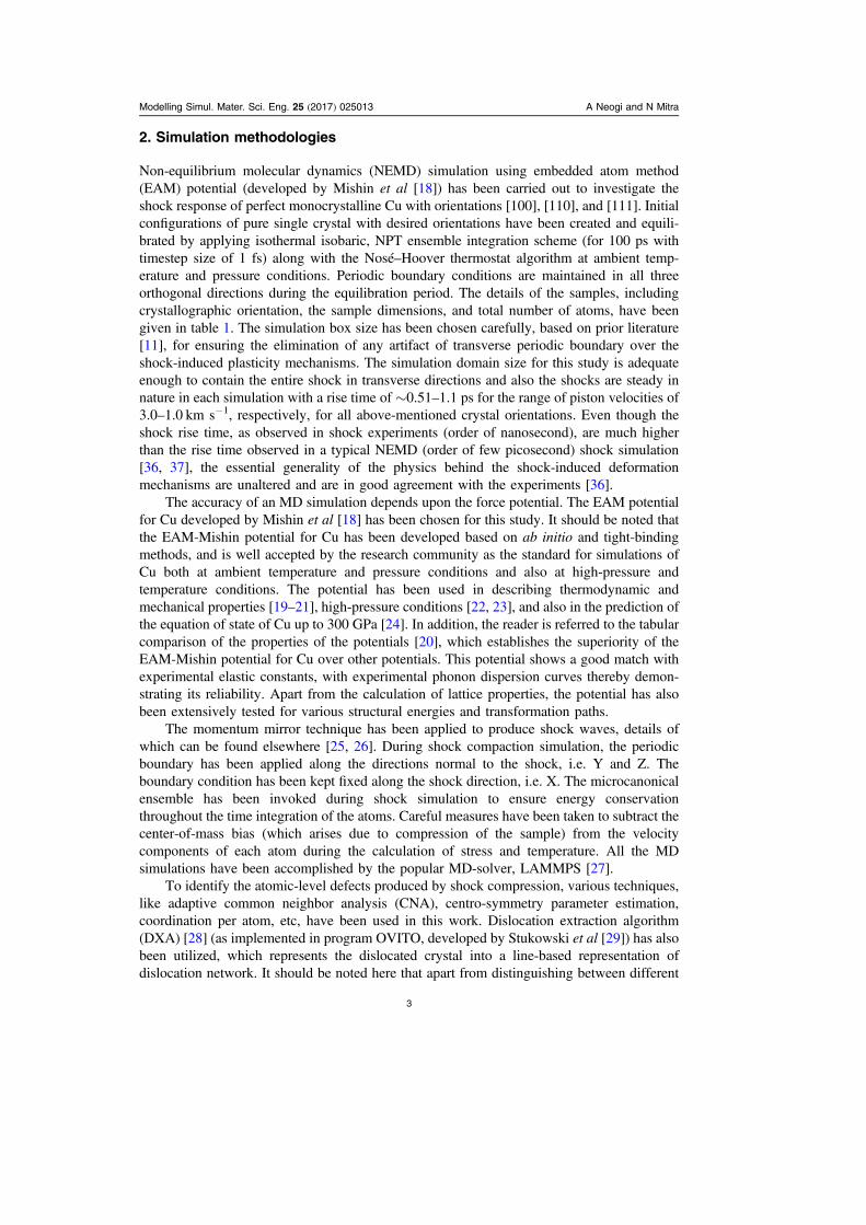
Figure 4. Temporal evolution of dislocation density (up to 16 ps) for shock loadingalong the 110⟨ ⟩ direction. All classified dislocations, including perfect dislocations (1/2110⟨ ⟩), Shockley partials(1 6 112⟨ ⟩), sessile partials, e.g. Hirth (1/3 001⟨ ⟩), Frank (1/3111⟨ ⟩,) and Stair-rod (1/6 110⟨ ⟩) have been plotted for the piston velocity of (a)0.85 km s−1 (i.e. shock pressure and temperature of ∼6.74 GPa and ∼335.12 K,respectively), (b) 1.5 km s−1 (i.e. shock pressure and temperature of ∼15.04 GPa and∼385.97 K, respectively), and (c) 2.0 km s−1 (i.e. shock pressure and temperature of∼125.75 GPa and ∼2415.31 K, respectively). In the inset, the zoomed figure has beenrepresented for visual clarity of the evolution of sessile dislocations. The dislocationdensity presented in the figure corresponding to a particular time instance has beenextracted from the entire shocked section of the target sample (which excludes the pre-shock volume) to envisage precisely the ongoing dislocation interactions behind theshock front.
Modelling Simul. Mater. Sci. Eng. 25 (2017) 025013 A Neogi and N Mitra
10

1
2110
1
2110
1
6211
1
6211
1
3100 1+ + +[¯ ] [¯ ¯ ] [¯ ¯] [¯ ¯ ] [¯ ] ( )
It should be noted that even though the mechanism of nucleation and evolution of Hirth lockshas been shown for the 100⟨ ⟩ direction at a piston velocity of 1 km s−1, similar types ofevolution mechanisms can be observed wherever a Hirth-lock mechanism is detected (forother crystallographic directions and impact velocities).
A detailed observation of the temporal evolution for sessile and perfect dislocations (asshown in the inset of figure 2) demonstrates that at pre-peak regime (piston velocity of0.85 km s−1), the Hirth-lock density is followed by the Stair-rod density and in fact thedensity of Stair-rods equals the Hirth-lock density at around 16 ps. This suggests that at a laterstage in the pre-peak regime there is a possibility of the formation of stable Lomer–Cottrelllocks instead of Hirth locks. On the other hand, perfect dislocation density can be observed inbetween the Hirth-lock density and the Stair-rod density for both the peak and the post-peakregime (piston velocity of 1 and 1.2 km s−1). Based on the trend of the curves, Hirth locks canbe described to have a higher propensity of formation compared to other types of sessile andperfect dislocations for the case of shock loading in the 100⟨ ⟩ direction. It should also benoted that for shock loading in this direction, there is a very small possibility of the formationof Frank loops in all regimes (pre-peak, peak, and post-peak). Typically, the reduction of totaldislocation elastic energy [38–41] and residual flow stress causes clustering of dislocationfragments into dislocation cells. The dislocation cell formation event has been observed in theregion (width of ∼250–350Å) near to the piston (i.e. far behind the shock front position);complete growth of the cells requires more time to be relaxed, which has been kept as futurescope for understanding dislocation cell formation after shock loading.
Figure 5. Atomistic configuration of cross-slips and associated jogs. The perpendicularof the paper plane represents the shock-propagation direction. Only hcp atoms (asidentified by DXA algorithm, implemented in OVITO [29]), owing to correspondingSFs, ribboned with green-colored wire-like dislocations have been represented. Black-colored circle and arrow indicate a cross-slip between two orthogonally aligned slipplanes, which have been denoted in the figure. Small, double-dashed yellow-coloredcircles (filled with semi-transparent color) indicate the jog segments.
Modelling Simul. Mater. Sci. Eng. 25 (2017) 025013 A Neogi and N Mitra
11
3.2. Shock propagation along ⟨110⟩
Figure 4 shows the temporal evolution of individual dislocation densities for shock loadingalong the 110⟨ ⟩ direction at different piston velocities (pre-peak at 0.85 km s−1, peak at1.5 km s−1, and post-peak at 2.0 km s−1
—refer to figure 1). Similar to that of the 100⟨ ⟩direction, Shockley partial density is significantly higher compared to that of the perfect aswell as the immobile dislocations. The nucleation of Shockley partials also starts almostimmediately with the passage of shock wave, whereas the other immobile dislocations resultfrom reactions of the Shockley partials after a few picoseconds. It should be noted that themaximum shear stress due to shock loading along the 110⟨ ⟩ direction is ∼17.06 GPa, which issignificantly higher than the maximum shear stress developed for shock compression alongthe 100⟨ ⟩ direction, ∼8.72 GPa at the peak dislocation density position for both orientations.
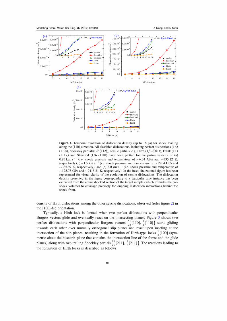
It is also observed that the rate of relaxation of developed shear stress is significantlylower in the case of the 110⟨ ⟩ direction than the high-symmetry 100⟨ ⟩ crystal orientation,which indicates the accumulation of residual shear stress in the low-symmetry direction,110⟨ ⟩. During the progression of the shock front, the gliding motion of the glissile dislocationis prevented by the dislocation forests or by the interaction of dislocations. However, theaccumulated residual shear stress in the case of 110⟨ ⟩ helps the dislocations to either climb,resulting in jog formation (refer to figure 5), or form perfect dislocations, which eventuallyglide in other planes (mechanism known in the literature as Schoeck–Seeger mechanism ofinteraction of cross-slips [43, 44], the formation of which is demonstrated in figure 6). Apartfrom residual shear stress, other factors such as high temperature and pressure along withcomplex alignment of operative slip planes in [110] are responsible for the evolution of bothmechanisms of cross-slip and jog formations. Typically, a jog formation is associated with anirreversible climbing motion, eventually resulting in a change in volume of the crystal [45].The average jog length is observed to increase with the increase of shock intensity, ascalculated from the extracted dislocation segments from DXA: at a piston velocity of 1.0 kms−1, the average jog length is ∼21.5Å, whereas it is ∼82.05Å at a piston velocity of 1.5 kms−1. The cross-slip mechanism as described by Schoeck–Seeger [43, 44] represents Shockleypartials in the primary glide plane recombined into a segment of perfect dislocation, whichdissociates and bows out into an inclined cross-slip plane, thereby transferring the dislocationto the new cross-slip plane.
Figure 6. Representation of temporal evolution of cross-slip event as observed for theshock-propagation direction of the 110⟨ ⟩-fcc. Figures (a) and (b) correspond to timeinstances of 8 and 12 ps, respectively. In figure (b), the bowing out of one perfectdislocation segment has been shown. Cylindrical, colored wires indicate the dislocationlines, where green, blue, pink, and yellow represent Shockley, perfect, Stair-rod, andHirth-type dislocations. Red-colored arrow indicates respective Burgers vectors of theassociated segments of the dislocations. Dashed-lined triangles are used to show therespective crystallographic planes.
Modelling Simul. Mater. Sci. Eng. 25 (2017) 025013 A Neogi and N Mitra
12

Temporal evolution of immobile dislocations in the pre-peak and peak regime shows thatStair-rod (resulting in the formation of sessile Lomer–Cottrell lock) and Hirth-type partials arethe two main competing candidates (see figure 4(a)). However, at higher piston velocities inthe post-peak regime (2.0 km s−1 piston velocity), Hirth-type dislocations overrule (seefigure 4(c)) other immobile dislocations. The mechanism of Hirth locks (see figure 3) hasbeen demonstrated before. The mechanism of the evolution of the Lomer–Cottrell lock isdemonstrated in figure 7. It should be noted that Lomer–Cottrell locks appear when twoperfect dislocations of the same 111{ } zone occur, gliding on different planes. The twoleading partials are attracted to one another and react along the 110⟨ ⟩ line of intersectionbetween the two planes to form a pure-edge 1101
6⟨ ⟩ Stair-rod partial dislocation referred to as
the Lomer–Cottrell lock. The reactions leading to the formation of Lomer–Cottrell locks isdescribed as follows:
1
2110
1
2101
1
2011 2+ [¯ ] [ ] [ ] ( )
These sessile dislocations (e.g. Hirth, Stair-rod, and Frank partials), as observed in thispresent study, act as pinning points and contribute differently to the strain hardening. Amongthese sessile locks, the Lomer–Cottrell lock (resulting from Stair-rod partials) offers thehighest impediment [46] to the dislocation glide, whereas Hirth locks possess greater strengthin comparison with Frank partials [47]. Interestingly, at high shock intensities, e.g. at a pistonvelocity of 2.0 km s−1, a significant decrease of Stair-rod dislocations has been observed (seefigure 4(c)), in comparison to that of the perfect dislocation segments. This disappearance of
Figure 7.Atomistic configuration of stair-rod type dislocation and formation of Lomer–Cottrell locks in the intersection of two orthogonal slip planes, (111) and (1 11¯ ¯), asobserved parallel to the shock-propagation direction. The perpendicular of the paperplane represents the shock-propagation direction, 110⟨ ⟩. Only hcp atoms (as identifiedby DXA algorithm, implemented in OVITO [29]), owing to corresponding SFs,ribboned with wire-like dislocations, have been represented. Pink, green, and yellowcolors represent Stair-rod (1/6 110⟨ ⟩), Shockley partials(1 6 112⟨ ⟩), and Hirth (1/3001⟨ ⟩) dislocations. The Burgers vector of all the dislocation segments has beenincluded in the figure.
Modelling Simul. Mater. Sci. Eng. 25 (2017) 025013 A Neogi and N Mitra
13

Lomer–Cottrell locks at high piston velocities might be because in order to form a stable andstrong sessile Lomer–Cottrell lock by reaction of two perfect dislocation segments, it isnecessary to have extrinsic SFs, which are higher in energy compared to intrinsic SFs.Thereby, there may be an increased tendency to form low-energy Hirth locks (throughintrinsic SFs) instead of high-energy Lomer–Cottrell locks, as evidenced from the classifieddislocation statistics in figure 4(c). The diminishing density of Stair-rod/Lomer–Cottrell locksat higher shock intensity might also be due to the polarity of the dislocation segments,because, to form Stair-rod partials two perfect dislocations (with opposite polarity) shouldattract each other and then react, but if they are found to have the same polarity no attractionwill occur and eventually no Stair-rod partials will be formed.
Quantification of operative slip systems in the 110⟨ ⟩-fcc shock-loading direction showsthat amongst all the slip systems in fcc, six of them (including conjugate slip systems),110 111 , 101 1 11[ ¯ ]( ¯ ¯ ) [ ¯ ¯]( ¯ ¯ ), and 110 111[ ¯ ¯ ]( ¯ ) have been observed to have been initiated and
Figure 8. Temporal evolution of dislocation density (up to 16 ps) for shock loadingalong the 111⟨ ⟩ direction. All classified dislocations, including perfect dislocations (1/2110⟨ ⟩), Shockley partials(1 6 112⟨ ⟩), sessile partials, e.g. Hirth (1/3 001⟨ ⟩), Frank (1/3111⟨ ⟩), and Stair-rod (1/6 110⟨ ⟩) have been plotted for the piston velocity of (a) 1.0 kms−1 (i.e. shock pressure and temperature of ∼6.91 GPa and ∼346.23 K, respectively),(b) 2.0 km s−1 (i.e. shock pressure and temperature of ∼123.15 GPa and ∼2392.69 K,respectively), and (c) 2.5 km s−1 (i.e. shock pressure and temperature of ∼156.38 GPaand ∼3567.52 K, respectively). In the inset, the zoomed figure has been represented forvisual clarity of the evolution of sessile dislocations. The dislocation density presentedin the figure corresponding to a particular time instance has been extracted from theentire shocked section of the target sample (which excludes the pre-shock volume) toenvisage precisely the ongoing dislocation interactions behind the shock front.
Modelling Simul. Mater. Sci. Eng. 25 (2017) 025013 A Neogi and N Mitra
14

contribute 34.2%, 28.7%, and 26.5%, respectively, to the total slip activity in the crystal,whereas, a small contribution (less than 20%) comes from 110 111 , 101 111[ ¯ ]( ) [ ¯ ¯]( ¯ ), and110 111[ ¯ ¯ ]( ¯ ). These calculations of the contribution of different slip systems shows goodconsistency with previous DD study by Shehadeh et al [16].
3.3. Shock propagation along ⟨111⟩
Temporal evolution of individual dislocation densities for shock loading along the 111⟨ ⟩direction at different piston velocities (pre-peak at 1.0 km s−1, peak at 2.0 km s−1, and post-peak at 2.5 km s−1
—see figure 1) are shown in figure 8. The rate of nucleation of Shockleypartial in the case of this direction is smaller than 110⟨ ⟩, but greater than 100⟨ ⟩. On the otherhand, the rate of nucleation of sessile dislocation has been observed to be the highest (seefigure 1(b)) in the 111⟨ ⟩ direction. The nature of dislocation distribution for the 111⟨ ⟩direction is quite similar to 110⟨ ⟩, but a significant amount of strain concentration can beidentified at the junctions or the point of reactions of the dislocations. Strain delocalizationphenomenon is also observed in this direction, which indicates a lesser probability of shearbanding. The equilibrium separation distance between the Shockley partials in this direction is
Figure 9. Atomistic configuration of evolution mechanism of an SFT has beendemonstrated in the above figure. (A) represents the onset of glide in three 111{ },which are oriented in a geometrically triangular fashion and aligned with 110⟨ ⟩,resulting in an SF and associated nucleation of Shockley partial (green-colored ribbon)and Stair-rod type (pink-colored ribbon) partials. (B)–(D) represent the temporalevolution of the dislocations and corresponding SFs, which eventually forms an SFT.Black-colored dashed line indicates the top view of a complete SFT, whereas, the red-colored arrow indicates the direction of the gliding of those participating SFs. Pleasenote, in the above configurations, only hcp atoms (as identified by the DXA algorithm)are presented.
Modelling Simul. Mater. Sci. Eng. 25 (2017) 025013 A Neogi and N Mitra
15
observed to be smaller than in other directions. Although the geometrical complexity of theslip planes is lower in comparison to 110⟨ ⟩, the mode of deformation, as observed from theatomic trajectories, is quite similar with 110⟨ ⟩, but the dynamics of dislocation activity differ alot, because reactions and/or the multiplication of dislocation primarily depend on geome-trical orientation of the containing glide planes and also associated energies. For the case ofshock propagation along 111⟨ ⟩ direction, four slip systems,101 111 , 101 111[ ¯ ¯]( ¯ ) [ ¯ ¯]( ¯ ¯ ), 011 111[ ¯ ¯]( ¯ ), and 011 111[ ¯ ¯]( ¯ ¯ ), are observed to have been activated inthe three different slip planes and contribute almost equally, congruous with earlier DDsimulation work [16]. Temporal evolution of the glissile dislocations show that for the pre-peak regime (piston velocity 1.0 km s−1) Stair-rod dislocations are marginally higher than theHirth-type dislocations. In fact, this observance is quite different compared to shock loadingin the other directions in which Hirth-type dislocations dominate the glissile dislocations.Even though, for higher shock intensities the Hirth-type locks are more frequent compared tothe Stair-rod dislocations. Thereby, it can be mentioned that the propensity of the formation ofHirth locks for this direction will be greater in the higher shock intensities compared to that oflow-shock intensities; whereas the propensity of the formation of Lomer–Cottrell locks willbe greater at low-shock intensities (pre-peak regime).
Interestingly, Frank partials are quite abundant compared to shock loading in otherdirections. The reason for this can be traced to the collateral orientation of the slip planes,which eventually results in a pattern of triangular-shaped geometry, thereby resulting in theformation of SF tetrahedra (SFT) i.e. Frank partials. The atomistic mechanism of evolution ofthe deformation-induced SFT [48] for Cu under shock loading is demonstrated in this articleand has been presented in figure 9. As is known, Frank partials are sessile, i.e. unable to glide,hence, they dissociate into a Shockley partial and Stair-rod to be unfaulted. In the atomisticconfiguration (see figures 9(A)–(D)) as extracted through DXA, it can be observed that theoriginated SFs are bounded by Shockley partials (green-colored wire) and also Stair-rods(pink-colored wire) confirming the unfaulting mechanism of Frank partials, which eventuallyhelps to form an SFT. It should be pointed out that these dislocation-originated SFT aredifferent from conventional SFT formation, which requires a vacancy (typically induced as aresult of irradiation and/or quenching). Typically, these dislocation-originated SFT are of anintrinsic type, which originates from dislocation interactions and contributes significantly tostrain hardening.
4. Conclusion
Shock loading of Cu in different directions shows orientation anisotropy. Significant differ-ences could be observed in the density of Shockley partials and other immobile dislocationsfor shock loading along different directions. The Shockley partials, which generate uponshock loading (beyond HEL point) for Cu in different orientations ( 100⟨ ⟩, 110⟨ ⟩, and 111⟨ ⟩),eventually interact to form different types of sessile locks. Observations of Hirth locks alongwith their atomistic evolution have been demonstrated for shock loading along the 100⟨ ⟩directions. Lomer–Cottrell locks have been observed to evolve for shock loadings in the 110⟨ ⟩direction. Apart from that, due to the presence of significant residual stresses, cross-slipmechanisms as well jogs are observed to form in the 110⟨ ⟩ direction; the atomistic evolutionof which has also been demonstrated for shock loading of materials. The formation ofdislocation-originated SFT for shock loading along the 111⟨ ⟩ direction; the evolution ofwhich is also demonstrated.
Modelling Simul. Mater. Sci. Eng. 25 (2017) 025013 A Neogi and N Mitra
16

Acknowledgments
A Neogi is grateful to the Indian Institute of Technology Kharagpur for providing a doctoralfellowship.
References
[1] Kalantar D H et al 2003 High-pressure, high-strain-rate lattice response of shocked materials Phys.Plasmas (1994-present) 10 1569–76
[2] Kalantar D H et al 2001 Laser driven high pressure, high strain-rate materials experiments Bull.APS (USA) 46 69
[3] Loveridge-Smith A et al 2001 Anomalous elastic response of silicon to uniaxial shockcompression on nanosecond time scales Phys. Rev. Lett. 86 2349
[4] Meyers M A, Benson D J, Vöhringer O, Kad B K, Xue Q and Fu H H 2002 Constitutivedescription of dynamic deformation: physically-based mechanisms Mater. Sci. Eng.: A. 322194–216
[5] Meyers M A, Gregori F, Kad B K, Schneider M S, Kalantar D H, Remington B A,Ravichandran G, Boehly T and Wark J S 2003 Laser-induced shock compression ofmonocrystalline copper: characterization and analysis Acta Mater. 51 1211–28
[6] Rivas J M, Quinones S A and Murr L E 1995 Hypervelocity impact cratering: microstructuralcharacterization Scr. Metall. Mater. 33 101–7
[7] Mogilevskii M A and Bushnev L S 1990 Deformation structure development in Al and Cu singlecrystal on shock-wave loading up to 50 and 100 GPa Combustion, Explosion, and Shock Waves26 215–20
[8] Schneider M S, Kad B K, Meyers M A, Gregori F, Kalantar D and Remington B A 2004 Laser-induced shock compression of copper: orientation and pressure decay effects Metall. Mater.Trans. A 35 2633–46
[9] Murr L E 1981 Residual microstructure-mechanical property relationships in shock loaded metalsand alloys Shock Waves and High Strain Rate Phenomena in Metals ed M A Meyers andL E Murr (New York: Plenum) pp 607–73
[10] Wright R N and Mikkola D E 1985 High strain rate deformation of Mo and Mo-33Re by shockloading: II. Rates of defect generation and accumulation of plastic strain Metall. Mater. Trans.A 16A 891–5
[11] Holian B L and Lomdahl P S 1998 Plasticity induced by shock waves in nonequilibriummolecular-dynamics simulations Science 280 2085–8
[12] Germann T C, Holian B L, Lomdahl P S and Ravelo R 2000 Orientation dependence in moleculardynamics simulations of shocked single crystals Phys. Rev. Lett. 84 5351
[13] Tanguy D, Mareschal M, Lomdahl P S, Germann T C, Holian B L and Ravelo R 2003 Dislocationnucleation induced by a shock wave in a perfect crystal: molecular dynamics simulations andelastic calculations Phys. Rev. B 68 144111
[14] Sichani M M and Spearot D E 2016 A molecular dynamics study of dislocation density generationand plastic relaxation during shock of single crystal Cu J. Appl. Phys. 120 045902
[15] Mackenchery K, Valisetty R R, Namburu R R, Stukowski A, Rajendran A M and Dongare A M2016 Dislocation evolution and peak spall strengths in single crystal and nanocrystalline CuJ. Appl. Phys. 119 044301
[16] Shehadeh M A, Zbib H M and De la Rubia T D 2005 Multiscale dislocation dynamics simulationsof shock compression in copper single crystal Int. J. Plast. 21 2369–90
[17] Weertman J 1981 Moving dislocations in a shock front Shock-wave and High Strain RatePhenomena in Metals ed M A Meyers and L E Murr (New York: Plenum) 469–86
[18] Mishin Yu et al 2001 Structural stability and lattice defects in copper: ab initio, tight-binding, andembedded-atom calculations Phys. Rev. B 63 224106
[19] Zheng L, An Q, Xie Y, Sun Z and Luo S N 2007 Homogeneous nucleation and growth of melt incopper J. Chem. Phys. 127 164503
[20] Bringa E M, Cazamias J U, Erhart P, Stölken J, Tanushev N, Wirth B D, Rudd R E andCaturla M J 2004 Atomistic shock Hugoniot simulation of single-crystal copper J. Appl. Phys.96 3793–9
Modelling Simul. Mater. Sci. Eng. 25 (2017) 025013 A Neogi and N Mitra
17

[21] Luo S N, Han L B, Xie Y, An Q, Zheng L and Xia K 2008 The relation between shock-stateparticle velocity and free surface velocity: a molecular dynamics study on single crystal Cu andsilica glass J. Appl. Phys. 103 093530
[22] He A M, Wang P, Shao J L, Duan S Q, Zhao F P and Luo S N 2014 Solid-liquid phase transitionsin single crystal Cu under shock and release conditions J. Appl. Phys. 115 143503
[23] Cai Y, Wang L, Wu H A, Zhu M H, Liu C L and Luo S N 2015 Homogeneous crystal nucleationin liquid copper under quasi-isentropic compression Phys. Rev. B 92 014108
[24] He A M, Duan S Q, Shao J L, Wang P and Luo S N 2013 Local and bulk melting of shockedcolumnar nanocrystalline Cu: dynamics, anisotropy, premelting, superheating, supercooling,and re-crystallization J. Chem. Phys. 139 074502
[25] Neogi A and Nilanjan M 2014 On shock response of nano-void closed/open cell copper material:Non-equilibrium molecular dynamic simulations J. Appl. Phys. 115 013504
[26] Holian B L and Peter S L 1998 Plasticity induced by shock waves in nonequilibrium molecular-dynamics simulations Science 280 2085–8
[27] Plimpton S 1995 Fast parallel algorithms for short-range molecular dynamics J. Comput. Phys.117 1–9
[28] Stukowski A and Albe K 2010 Extracting dislocations and non-dislocation crystal defects fromatomistic simulation data Modelling Simul. Mater. Sci. Eng., 18 085001
[29] Stukowski A 2009 Visualization and analysis of atomistic simulation data with OVITO—the openvisualization tool Modelling Simul. Mater. Sci. Eng. 18 015012
[30] Stukowski A, Bulatov V V and Arsenlis A 2012 Automated identification and indexing ofdislocations in crystal interfaces Modelling Simul. Mater. Sci. Eng. 20 085007
[31] Stukowski A and Arsenlis A 2012 On the elastic-plastic decomposition of crystal deformation atthe atomic scale Modelling Simul. Mater. Sci. Eng. 20 035012
[32] http://math.lbl.gov/voro++/; a software library for carrying out three-dimensional computationsof the Voronoi tessellation
[33] Seif D, Po G, Crum R, Gupta V and Ghoniem N M 2014 Shock-induced plasticity and theHugoniot elastic limit in copper nano films and rods J. Appl. Phys. 115 054301
[34] Shimizu F, Ogata S and Li J 2007 Theory of shear banding in metallic glasses and moleculardynamics calculations Mater. Trans., 48 2923–7
[35] Falk M L and Langer J S 1998 Dynamics of viscoplastic deformation in amorphous solids Phys.Rev. E 57 7192
[36] Cao B, Bringa E M and Meyers M A 2007 Shock compression of monocrystalline copper:Atomistic simulations Metall. Mater. Trans., A 38 2681–8
[37] Milathianaki D et al 2013 Femtosecond visualization of lattice dynamics in shock-compressedmatter Science 342 220–3
[38] Nabarro F R, Basinski Z S and Holt D B 1964 The plasticity of pure single crystals Adv. Phys. 13193–323
[39] Nine H D and Kuhlmann-Wilsdorf D 1967 Fatigue in copper single crystals and a new model offatigue in face-centered cubic metals Can. J. Phys. 45 865–81
[40] KuhlmannWilsdorf D, Laufer E E and Nine H 1967 Formation of fatigue striations in fcc metalsJ. Appl. Phys. 38 896–8
[41] KuhlmannWilsdorf D and Nine H D 1967 Striations on copper single crystals subjected totorsional fatigue: II. On the mechanism of fatigue striation formation and fatigue failure at lowstrain amplitudes J. Appl. Phys. 38 1683–93
[42] Neogi A and Mitra N 2016 Body-centered phase of shock loaded Cu arXiv:1607.06202[43] Seeger A 1957 The mechanism of glide and work-hardening in face-centered cubic and hexagonal
close-packed metal Dislocations and Mechanical Properties of Crystals (New York: Wiley)[44] Schoeck G and Seeger A 1955 Defects in Crystalline Solids (London: Physical Society) 340[45] Friedel J 1964 Dislocations (Oxford: Pergamon) 274[46] Franciosi P, Berveiller M and Zaoui A 1980 Latent hardening in copper and aluminium single
crystals Acta Metall. 28 273–83[47] Martinez E, Marian J, Arsenlis A, Victoria M and Perlado J M 2008 Atomistically informed
dislocation dynamics in fcc crystals J. Mech. Phys. Solids 56 869–95[48] Wang J W, Narayanan S, Huang J Y, Zhang Z, Zhu T and Mao S X 2013 Atomic-scale dynamic
process of deformation-induced stacking fault tetrahedra in gold nanocrystals Nat. Commun.4 2340
Modelling Simul. Mater. Sci. Eng. 25 (2017) 025013 A Neogi and N Mitra
18


![Synthesis and thermal decomposition of copper(I) silyloxide complexes. X-ray crystal structures of [Cu(OSiPh3)]4 and [Cu(OSiPh3)(PMe2Ph)]2](https://static.fdokumen.com/doc/165x107/6332e2d9576b626f850d9f7a/synthesis-and-thermal-decomposition-of-copperi-silyloxide-complexes-x-ray-crystal.jpg)


![Coordination Behavior of Sulfathiazole: Crystal Structure of [Cu(en)2(OH2)2][Sulfathiazole]2·2H2O (en = ethylenediamine): Antibacterial activity](https://static.fdokumen.com/doc/165x107/632171d080403fa2920cc030/coordination-behavior-of-sulfathiazole-crystal-structure-of-cuen2oh22sulfathiazole22h2o.jpg)


