Severe deformation twinning in pure copper by cryogenic wire drawing
8
Severe deformation twinning in pure copper by cryogenic wire drawing A. Kauffmann a,b , J. Freudenberger a,c,⇑ , D. Geissler a,b , S. Yin a,b , W. Schillinger d , V. Subramanya Sarma e , H. Bahmanpour f , R. Scattergood f , M.S. Khoshkhoo a , H. Wendrock a , C.C. Koch f , J. Eckert a,b , L. Schultz a,b a IFW Dresden, P.O. Box 270116, 01171 Dresden, Germany b TU Dresden, Institute of Materials Science, 01062 Dresden, Germany c TU Bergakademie Freiberg, Institute of Materials Science, 09596 Freiberg, Germany d Wieland-Werke AG, Graf-Arco-Straße 36, 89079 Ulm, Germany e Department of Metallurgical and Materials Engineering, Indian Institute of Technology Madras, Chennai 600 036, India f Department of Materials Science and Engineering, North Carolina State University, Engineering Building I, 911 Partner’s Way, Raleigh, NC 27695-7907, USA Received 28 June 2011; received in revised form 23 August 2011; accepted 27 August 2011 Available online 20 October 2011 Abstract The effect of low-temperature on the active deformation mechanism is studied in pure copper. For this purpose, cryogenic wire draw- ing at liquid nitrogen temperature (77 K) was performed using molybdenum disulfide lubrication. Microstructural investigation and tex- ture analysis revealed severe twin formation in the cryogenically drawn copper, with a broad twin size distribution. The spacing of the observed deformation twins ranges from below 100 nm, as reported in previous investigations, up to several micrometers. The extent of twin formation, which is significantly higher when compared to other cryo-deformation techniques, is discussed with respect to the state of stress and the texture evolution during wire drawing. Ó 2011 Acta Materialia Inc. Published by Elsevier Ltd. All rights reserved. Keywords: Deformation twinning; Copper; Low-temperature deformation; Stress state; Resolved shear stress 1. Introduction Nanostructured materials have been the subject of intense research activity over the last few decades due to their properties, which appear to be outstanding in many cases. Structuring of these materials can occur with reduced dimensionality, based on the morphology of the nanometer-sized microstructural elements. For example, Lu et al. [1,2] showed that the formation of growth twin lamellas of about 15 nm twin spacing and twin lengths of 100 nm to 1 lm during electrodeposition in pure Cu leads to excellent mechanical properties. They observed an increase in ultimate tensile strength up to about 1070 MPa, combined with 14% elongation to failure and an electrical resistivity of about 1.75 10 8 Xm, which is similar to that of pure Cu in the annealed state. These properties are directly attributed to the nanoscale twinned microstructure. However, as such microstructures are formed during a deposition process, the production of these materials is restricted in at least one dimension. Nevertheless, Lu et al. [1] stated that twinning is a common phenomenon in nature. It occurs during growth processes, recrystallization, phase transformations or deformation. This opens the possibility of expanding the approach to processes other than electrodeposition. After several years of reservations regarding deforma- tion twinning in pure Cu, Blewitt et al. [3] provided unam- biguous evidence for this deformation mode in Cu single crystals at low temperature. Subsequent investigations revealed the typical characteristics of deformation twinning 1359-6454/$36.00 Ó 2011 Acta Materialia Inc. Published by Elsevier Ltd. All rights reserved. doi:10.1016/j.actamat.2011.08.042 ⇑ Corresponding author at: IFW Dresden, P.O. Box 270116, 01171 Dresden, Germany. Tel.: +49 351 4659 550; fax: +49 351 4659 500. E-mail address: [email protected] (J. Freudenberger). www.elsevier.com/locate/actamat Available online at www.sciencedirect.com Acta Materialia 59 (2011) 7816–7823
Transcript of Severe deformation twinning in pure copper by cryogenic wire drawing

Available online at www.sciencedirect.com
www.elsevier.com/locate/actamat
Acta Materialia 59 (2011) 7816–7823
Severe deformation twinning in pure copper by cryogenic wire drawing
A. Kauffmann a,b, J. Freudenberger a,c,⇑, D. Geissler a,b, S. Yin a,b, W. Schillinger d,V. Subramanya Sarma e, H. Bahmanpour f, R. Scattergood f, M.S. Khoshkhoo a,
H. Wendrock a, C.C. Koch f, J. Eckert a,b, L. Schultz a,b
a IFW Dresden, P.O. Box 270116, 01171 Dresden, Germanyb TU Dresden, Institute of Materials Science, 01062 Dresden, Germany
c TU Bergakademie Freiberg, Institute of Materials Science, 09596 Freiberg, Germanyd Wieland-Werke AG, Graf-Arco-Straße 36, 89079 Ulm, Germany
e Department of Metallurgical and Materials Engineering, Indian Institute of Technology Madras, Chennai 600 036, Indiaf Department of Materials Science and Engineering, North Carolina State University, Engineering Building I, 911 Partner’s Way, Raleigh, NC
27695-7907, USA
Received 28 June 2011; received in revised form 23 August 2011; accepted 27 August 2011Available online 20 October 2011
Abstract
The effect of low-temperature on the active deformation mechanism is studied in pure copper. For this purpose, cryogenic wire draw-ing at liquid nitrogen temperature (77 K) was performed using molybdenum disulfide lubrication. Microstructural investigation and tex-ture analysis revealed severe twin formation in the cryogenically drawn copper, with a broad twin size distribution. The spacing of theobserved deformation twins ranges from below 100 nm, as reported in previous investigations, up to several micrometers. The extent oftwin formation, which is significantly higher when compared to other cryo-deformation techniques, is discussed with respect to the stateof stress and the texture evolution during wire drawing.� 2011 Acta Materialia Inc. Published by Elsevier Ltd. All rights reserved.
Keywords: Deformation twinning; Copper; Low-temperature deformation; Stress state; Resolved shear stress
1. Introduction
Nanostructured materials have been the subject ofintense research activity over the last few decades due totheir properties, which appear to be outstanding in manycases. Structuring of these materials can occur withreduced dimensionality, based on the morphology of thenanometer-sized microstructural elements. For example,Lu et al. [1,2] showed that the formation of growth twinlamellas of about 15 nm twin spacing and twin lengths of100 nm to 1 lm during electrodeposition in pure Cu leadsto excellent mechanical properties. They observed anincrease in ultimate tensile strength up to about
1359-6454/$36.00 � 2011 Acta Materialia Inc. Published by Elsevier Ltd. All
doi:10.1016/j.actamat.2011.08.042
⇑ Corresponding author at: IFW Dresden, P.O. Box 270116, 01171Dresden, Germany. Tel.: +49 351 4659 550; fax: +49 351 4659 500.
E-mail address: [email protected] (J. Freudenberger).
1070 MPa, combined with 14% elongation to failure andan electrical resistivity of about 1.75 � 10�8 Xm, which issimilar to that of pure Cu in the annealed state. Theseproperties are directly attributed to the nanoscale twinnedmicrostructure. However, as such microstructures areformed during a deposition process, the production ofthese materials is restricted in at least one dimension.Nevertheless, Lu et al. [1] stated that twinning is a commonphenomenon in nature. It occurs during growth processes,recrystallization, phase transformations or deformation.This opens the possibility of expanding the approach toprocesses other than electrodeposition.
After several years of reservations regarding deforma-tion twinning in pure Cu, Blewitt et al. [3] provided unam-biguous evidence for this deformation mode in Cu singlecrystals at low temperature. Subsequent investigationsrevealed the typical characteristics of deformation twinning
rights reserved.

A. Kauffmann et al. / Acta Materialia 59 (2011) 7816–7823 7817
in single-valent noble metals. Briefly, the characteristicshave been discussed with regard to the dependence of thetwinning stress on temperature, orientation, direction ofloading and solute content in single-phase alloys [4].Recently, the transition from pure slip to slip and twin-dominated plasticity was investigated by comparison ofroom temperature and cryogenic temperature deformation,as well as by variation of stacking fault energy [5]. In thepresent investigation, the basic knowledge about thedependence of deformation twinning on orientation andtemperature is rigorously applied in order to produceseverely and homogeneously twinned microstructures inpure Cu, i.e. without influencing the stacking fault energyby additional alloying.
As Blewitt et al. [3] showed in their first investigation,deformation twinning in pure Cu only occurs under certainconditions. These are depicted by means of Fig. 1, whichsummarizes several different experimental observations.During a more detailed study, Mitchell and Thornton [6]obtained distinct differences in the stress–strain behaviourof Cu single crystals deformed at different temperatures,as shown in Fig. 1a. At room temperature, plasticity ismediated by dislocation slip and dynamic recovery inhibitsthe formation of deformation twins by retaining a compar-atively low stress level. When the temperature is lowereddown to that of liquid nitrogen (77 K) and below, twinningin pure Cu can be activated by suppression of dynamicrecovery and thus increasing stress level [4]. Furthermore,
(a)
(b)Fig. 1. Twinning in Cu single crystals under tensile load: (a) stress-strainresponse with respect to twinning at different temperatures in Cu crystalsof an orientation suitable for twinning [6], (b) orientation dependence oftwinning at cryogenic and room temperature [3,6–10].
twinning shows a strong orientation dependence, as illus-trated in Fig. 1b [3,6–10]. At a temperature of 77 K, twin-ning is observed mainly in crystals with the tensile axisparallel to h1 1 1i, while h1 0 0i-oriented crystals do notexhibit twin formation. In contrast, under compressionload, twinning occurs in crystals oriented near h1 0 0i andis absent in crystals oriented near h1 1 1i [4]. The rangeof orientation under tensile loading is extended when com-pared to compressive loading.
The aim of the present study is to analyse the impact of thestate of stress and the texture evolution on twin formationduring wire drawing at liquid nitrogen temperature. This isdone in order to provide a homogeneously fine twinnedmicrostructure within a technically relevant deformationprocess. For this purpose, a suitable cryogenic drawing(cryo-drawing) set-up, including a sufficient lubricationmethod, that allows the process to be adapted to a technicallyreasonable working window has been developed and tested.
2. Experimental
The experiments for this study are divided into twoparts. In the first part, the cryo-drawing process was stud-ied and optimized. In the second one, this optimized pro-cess was applied to the sample preparation for the studyof the microstructure and texture in cryo-deformed Cu.
The starting material for the development of the cryo-drawing process was commercially available Cu-OF(CW007A, EN 1977), 6 mm in diameter and 50 cm inlength. Drawing dies with a cone angle of 2a = 12� wereused. Prior to each drawing step of about 0.2 logarithmicdeformation strain, g, the Cu wire and the dies wereimmersed in liquid nitrogen. The cold rod material wasthen drawn through the die out of the cooling bath at aspeed of 0.5 m min�1. In order to assess different lubri-cants, the drawing forces were recorded using a computer-ized data acquisition system connected to cells of either 5or 30 kN load. The lubricants tested are bonded coatingsof polytetrafluoroethylene (PTFE, PRO 407 GT by Pro-line�), graphite (PRO 437 GG by Proline�) and molybde-num disulphide (MoS2; PRO 417 GM by Proline�). Forcomparison, a state-of-the-art drawing oil (Rotanor SCMby Rhenus Lub) was used at room temperature.
For the study of deformation twinning in cryo-drawnCu, the primary material was pre-processed in order toachieve a suitable microstructure and texture. Cu-OFE(CW009A, EN 1977) was melted in an induction furnaceand cast into a cylindrical graphite mould in an Ar atmo-sphere. After machining the ingot to D = 28.5 mm, a hotforming process at 600 �C via rotary swaging down toD = 25.0 mm was adopted in order to remove the as-castmicrostructure. A post-annealing treatment at 800 �C for18 h in an Ar atmosphere resulted in a coarse-grainedmicrostructure for the subsequent drawing process. Thisstarting material was deformed to a final diameter of11.8 mm by wire drawing, with about 0.1 logarithmicdeformation per step at a speed of about 0.5 m min�1.

7818 A. Kauffmann et al. / Acta Materialia 59 (2011) 7816–7823
Lubrication via drawing oil was used at room temperature,while MoS2 lubrication was chosen for the cryo-drawingprocess in a bath of liquid nitrogen.
Microstructural characterization was carried out byscanning electron microscopy (SEM) using Leo Gemini1530 and Philips XL20 microscopes. Secondary electronimages were taken at 15 up to 20 kV, except for the charac-terization of the PTFE-bonded lubricant coatings, whichwere taken at an acceleration voltage of 1 kV. Forwardscattered electron images were recorded using a four-diodeforescatter detector. The samples were prepared by a con-ventional metallographic procedure, completed by a finish-ing step using a VibroMet� 2 vibratory polishing machineand Mastermet� 2 suspension (both by Buehler) for about8 h.
The global texture was measured by the X-ray diffrac-tion Schulz reflection method on a Philips X’Pert MRDsystem operating with Cu Ka radiation. The pole figureswere corrected for background (2� in 2H next to the corre-sponding reflection), defocusing and tilt (the h1 1 1i fibretexture component parallel to the wire axis). The defocus-ing functions were obtained on a polycrystalline, non-tex-tured sample prepared from a non-flowing, fine dendriticpowder.
Local texture information was obtained from the metal-lographically prepared samples by electron backscatter dif-fraction (EBSD). The acquisition of orientation data wasaccomplished with a Nordlys EBSD system in a three-stepindexing process. Drifts during the scans were correctedafterwards for the visible shape of carbon contaminationin secondary electron contrast, indicating the scannedsurface area.
3. Results and discussion
3.1. Lubrication
Unlike rolling at cryogenic temperature, wire drawing isdifficult to perform because of the need of an appropriate
(a) (b)Fig. 2. Scanning electron micrographs (secondary electron contrast) at differencoatings used in the present investigation: (a) graphite (dense coating top left
lubrication. State-of-the-art lubricants at room tempera-ture are mainly drawing oils, emulsions or powders. How-ever, all conventional liquid lubricants, like drawing oils,cannot be used at liquid nitrogen temperature. Thus, solidlubricants have to be applied. The lubricants used in thepresent study are inspired by recent developments in aero-space engineering. There are materials such as MoS2 [11],graphite or PTFE [12] and composites thereof [13,12], rep-resenting prominent examples for sacrificial coatings orself-lubricating systems. They provide solid shape, vacuumand temperature stability. For technical reasons, the appli-cation of the lubricant would have to ensure a repeatedlubrication of reproducible quality after every drawingstep. Therefore, bonded coatings are suitable. These com-mercially available separating agents or lubricants can beeasily applied by spraying.
Fig. 2 shows SEM micrographs of the investigatedbonded coatings. All lubricants form dense coatings exceptgraphite, for which dense coatings can be shown to beinterrupted by flawed surface areas several hundredmicrometers in diameter. In the case of MoS2 and graphite,the coatings consist of platelets of 5–20 lm and 2–10 lm,respectively. The PTFE coating does not exhibit separateparticles on the wire surface. All coatings are stable againstshock cooling down to 77 K in liquid nitrogen.
As an example for the qualification of the three bondedcoatings on Cu, the recorded drawing force during thedrawing step from 6 to 5.4 mm in a bath of liquid nitrogenis shown in Fig. 3a. It is not possible to draw uncoatedmaterial because the load stress of about 370 MPa(8.5 kN) exceeds the ultimate tensile strength of the wireand failure after necking is observed. By means of bondedcoatings, the load stress can be reduced down to about260 MPa (6.0 kN, PTFE), 225 MPa (5.2 kN, graphite)and 200 MPa (4.6 kN, MoS2). The force characteristicsduring the drawing process are also quite different. Whilethe PTFE coating provides a constant and homogeneousforce profile, the graphite coating exhibits a continuousdecrease in drawing force after an overshoot at the
(c)t magnifications (overview on the left; in detail on the right) of the bondedand porous coating bottom left), (b) MoS2 and (c) PTFE.

(a) (b)
(c)Fig. 3. Drawing force as a function of time during wire drawing. Drawing takes place in a bath of liquid nitrogen: (a) comparison between non-lubricationand various bonded coatings and (b) drawing series of MoS2 bonded coating. The drawing force of standard lubrication at room temperature is includedin (a) for comparison. The wire surface at the final stage of the drawing process is shown in (c) as scanning electron micrographs (secondary electroncontrast) at different magnifications after removal of the coating.
A. Kauffmann et al. / Acta Materialia 59 (2011) 7816–7823 7819
beginning of the drawing process. The MoS2 coating showsthe lowest average drawing force, but is less constant overtime than PTFE and graphite. Fig. 3b depicts the evolutionof the drawing force characteristic over several deforma-tion steps with the MoS2 coating. It can be seen that thecoating stabilizes with reduced average drawing force. Aninspection of the final wire surface after the last drawingstep reveals pronounced die lines. As a consequence,although the MoS2 coating is the system of choice for thefollowing study, there is still potential for lubricant optimi-zation with respect to application.
3.2. Stress state
The dominant deformation mechanisms in face-centredcubic metals – dislocation slip and twinning – are shear sen-sitive because they are both based on the movement of dis-locations. Hence, if other constraints to twinning arefulfilled, the resolved shear stress distribution during thedeformation process will determine the active deformationmechanism. A rough approximation of the resolved shearstress distribution during wire drawing can be obtainedby using the elementary circular slab method of plasticity
[14–16] to estimate the state of stress and calculate the cor-responding resolved shear stresses.
A resolved shear stress s on a shear plane with a normalp in a shear direction d (p and d are used as unit vectors)caused by a multiaxial stress state r is described by the pro-jection s = d � r � p. Using the principal coordinate systemwith the principal stresses rx, ry and rz, this can betransformed into:
s ¼ d � r � p ð1Þ¼ dxpxrx þ dypyry þ dzpzrz ð2Þ¼ dypyðry � rxÞ þ dzpzðrz � rxÞ ð3Þ
where pi and di denote the coordinates of p and d in theprincipal coordinate system. The simplification fromEqs. (2) and (3) follows from the orthogonality of shearplane normal and shear direction p � d = 0. By assuminghomogeneous deformation and conservation of volume,a principal stress distribution (without back pull) asshown in Fig. 4 can be obtained using circular slabs[15,16]. This state of stress r can be rearranged torx = ry = (R(z) � 1)r and rz = R(z)r, where 0 6 R(z) < 1and r > 0 separate the local dependence and scaling

Fig. 4. Scheme of wire drawing and stress state during wire drawing [15,16].
7820 A. Kauffmann et al. / Acta Materialia 59 (2011) 7816–7823
dependence of the stress state throughout the drawing die.Eq. (3) is then reduced to:
s ¼ dzpzr ð4ÞHence, the resolved shear stress determining the micro-structural mechanisms of deformation is simply a functionof the axial tensile stress at the back relief rz(zR) = R(zR)rand the projections of the shear elements, dzpz (e.g. the Bur-gers vector and slip plane) onto the wire axis. In a polycrys-talline material these projections are determined by thetexture components present. The resolved shear stress isindependent of the exact position in the drawing die andsimilar to that of tensile testing. Thus, dislocation andtwinning-mediated plasticity will occur during the wholedeformation process if the necessary orientation relationsare fulfilled by the texture evolution and the required stresslevel is reached. Further, these requirements can be easilydeduced from tensile testing (see Section 1) due to the strik-ing similarity of the resolved shear stresses.
In contrast, the approximately biaxial state of stress dur-ing rolling with very different stress components along therolling direction, rz, and along the normal direction, rx,leads to:
s ¼ dxpxrx þ dzpzrz ð5ÞIn this case, a separation of scaling and local dependence ofany kind cannot produce a location-independent result.Thus, the aforementioned requirements for deformationtwinning with respect to the state of stress cannot be
Fig. 5. The {1 1 1} pole figures on the wire cross-sections at different logarithnitrogen temperature.
equally matched over the complete deformed zone as inthe case of wire drawing.
These approximations are, of course, rather rough. Theactual stress states are influenced by the boundary condi-tions of friction and the criteria of plastic flow. Thereforethe principal stresses are not aligned with the sample coor-dinate system, as it is assumed in elementary plasticity the-ory. Nevertheless, a detailed study of the state of stressduring wire drawing [17] first reveals one path along theradial direction with perfectly aligned principal stresses.Secondly, rr � rt and accordingly rx � ry are suitableapproximations. Hence, elementary plasticity theory pro-vides a simple way to estimate the potential of wire drawingfor the initiation of severe, homogeneous twin formationduring plastic deformation when compared to other defor-mation methods.
3.3. Texture evolution
As described in Section 1, twinning occurs under tensileloads (or stress states that reproduce the same resolvedshear stress distribution) near h1 1 1i directions. Duringconventional wire drawing processes, mixed h1 1 1i/h1 0 0i fibre textures develop with a strong h1 1 1i fibrecomponent in face-centred cubic materials [18]. The textureevolution during the cryogenic wire drawing process istracked using the {1 1 1} pole figures on the wire cross-sections, as shown in Fig. 5. The almost non-textured,
mic degrees of deformation, g, within the wire drawing process at liquid

Fig. 6. Scanning electron micrograph (forward scattered electron con-trast) of the severely twinned microstructure obtained by drawing atcryogenic temperature. The logarithmic degree of deformation is g = 1.5.
A. Kauffmann et al. / Acta Materialia 59 (2011) 7816–7823 7821
coarse-grained initial state develops towards a h1 1 1i fibrecomponent-dominated texture indicated by the maximumat the center of the pole figure within the first steps ofdeformation. At a logarithmic degree of deformation ofg = 0.30 this texture component exhibits an intensity ofabout 3 m.u.d. (multiples of the uniform distribution),which increases to about 5 m.u.d. at the final stage ofdeformation.
3.4. Microstructure
The suppression of dynamic recovery by cryogenicdeformation leads to twin formation in Cu. Therefore,enhanced mechanical properties and changed response toheat treatments when compared to conventionally pre-pared Cu are to be expected. This was shown previouslyby Brandao et al. [19,20] and Han et al. [21] for drawnwires, Zhao et al. [22] for drawing after equal channelangular pressing, Zhao et al. [23] and Li et al. [24] fordynamically deformed bars and Jia et al. [25] for rolledtapes. In general, the reported twin spacings are below100 nm, i.e. <100 nm for drawn wires [21], several nanome-ters to about 85 nm for drawing after equal channel angu-lar pressing [22], and between 10 and 150 nm (with anaverage of 40 nm) [23] and 2 and 5 nm for rolled tapes[25]. Corresponding twin densities are rarely given in theliterature, though Zhao et al. [23] estimated the twin den-sity to be about 2.5 � 107 m2 m�3. The above-mentionedexperiments were performed using transmission electronmicroscopy. Thus, it is not clear whether the results arerepresentative of the complete microstructure and all thetexture components arising during deformation. Recently,an extended study by Konkova et al. [26] revealed thatdeformation twinning does not contribute substantially tograin refinement during cryo-rolling despite the numerousobservations of nanoscaled twins in cryo-deformedmaterials.
In addition to the microstructural response, a texturetransition from copper-type to brass-type rolling textureis observed by comparing Cu rolled at room temperatureand 77 K [27,26]. This texture transition is mainly charac-terized by an abrupt decrease in the {1 1 2}h1 1 1i compo-nent, which is mainly governed by mechanical twinningand suppressed cross-slip [28,26]. Since the total volumefraction of suitable orientations (concerning the resolvedshear stress) is restricted to less than 50% [28], the probabil-ity of extended deformation twinning is restricted, too.Regarding the discussion in Sections 1 and 3.2, this isattributed to a location-dependent state of stress that fulfilsthe conditions of deformation twinning only for a limitednumber of texture components. This is perhaps one ofthe major reasons for the observations in Ref. [26]. In con-trast, wire drawing at liquid nitrogen temperature providesoutstanding characteristics because of a virtually location-independent resolved shear stress (Section 3.2) and adominant h1 1 1i fibre texture component (Section 3.3).Thus, the conditions for deformation twinning (Section 1)
that appear homogeneously in the main part of the micro-structure are fulfilled.
The resulting microstructure obtained by wire drawing atliquid nitrogen temperature is shown in Fig. 6. It is domi-nated by grains in the range of 100–500 lm intersected byfine thin lamellae of a few nanometers up to several microm-eters in width. These lamellae are identified as deformationtwins and are not present following wire drawing at roomtemperature. The upper end of this length scale is mainlyattributed to primary deformation twins while the lowerend is mainly due to secondary deformation twins. Fig. 6illustrates that the spacings of these primary deformationtwins greatly exceed the before-mentioned values reportedin the literature. Additionally, only a few parts of the micro-structure are free of twins. Unfortunately, an evaluation ofthe corresponding twin density for the complete microstruc-ture is not possible by stereographic methods because of thelarge range of twin spacings.
In order to validate the formation of deformation twins,local texture analyses using electron backscatter diffractionwere performed. The microstructure following a conven-tional drawing process at room temperature is shown inFig. 7. The grains are highly distorted and exhibit orienta-tions mainly with the h1 1 1i- or h1 0 0i-crystallographicaxis parallel to the wire axis. These are indicated by blueand red in Fig. 7a, and can also be seen in the correspond-ing inverse pole figure in Fig. 7b. The contouring of theinverse pole figure in Fig. 7b reveals that the two texturecomponents are indeed close to the ideal sites of theh1 1 1i/h1 0 0i fibre texture components. There is less inten-sity at the ideal site of twins in h1 1 1i fibre-orientatedgrains, which corresponds to h1 1 5i fibre orientations.Annealing twins present in the initial microstructure rotatetowards the h1 0 0i fibre site during wire drawing and arethus not observed at the h1 1 5i fibre site. Additionally,
(a) (b)Fig. 7. EBSD analysis of a cross-section of Cu drawn at room temper-ature (g = 1.5): (a) orientation map according to the inverse pole figure(grain boundaries in black, twin boundaries in green) and (b) thecorresponding inverse pole figure (combined occupancy and contourdiagram). The steps size was 1 lm. Warping of the image is due to off-linedrift correction. Contours indicate multiples of the uniform distribution.
7822 A. Kauffmann et al. / Acta Materialia 59 (2011) 7816–7823
as already mentioned, the microstructure is free of the thinintersecting lines that indicate deformation twins.
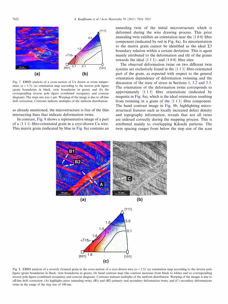
In contrast, Fig. 8 shows a representative image of a partof a h1 1 1i fibre-orientated grain in a cryo-drawn Cu wire.This matrix grain (indicated by blue in Fig. 8a) contains an
(a)
(c)Fig. 8. EBSD analysis of a severely twinned grain in the cross-section of a cryfigure (grain boundaries in black, twin boundaries in green), (b) band contrasinverse pole figure (combined occupancy and contour diagram). Contours indioff-line drift correction. (A) highlights prior annealing twins; (B1) and (B2) prtwins in the range of the step size of 100 nm.
annealing twin of the initial microstructure which isdeformed during the wire drawing process. This priorannealing twin exhibits an orientation near the h1 0 0i fibrecomponent (indicated by red in Fig. 8a). Its misorientationto the matrix grain cannot be identified as the ideal R3boundary relation within a certain deviation. This is againmainly attributed to the deformation and tilt of the grainstowards the ideal h1 1 1i- and h1 0 0i fibre sites.
The observed deformation twins on two different twinsystems are exclusively found in the h1 1 1i fibre-orientatedpart of the grain, as expected with respect to the generalorientation dependence of deformation twinning and thediscussion of the state of stress in Sections 1, 3.2 and 3.3.The orientation of the deformation twins corresponds toapproximately h1 1 5i fibre orientations (indicated bymagenta in Fig. 8a), which is the ideal orientation resultingfrom twinning in a grain of the h1 1 1i fibre component.The band contrast image in Fig. 8b, highlighting micro-structural features such as locally increased defect densityand topography information, reveals that not all twinsare indexed correctly during the mapping process. This isattributed mainly to overlapping Kikuchi patterns. Thetwin spacing ranges from below the step size of the scan
(b)
o-drawn wire (g = 1.5): (a) orientation map according to the inverse polet map (the contrast increases from black to white) and (c) correspondingcate multiples of the uniform distribution. Warping of the images is due toimary and secondary deformation twins; and (C) secondary deformations

A. Kauffmann et al. / Acta Materialia 59 (2011) 7816–7823 7823
of 100 nm up to several micrometers. This extends theobservations of [19,20] concerning the density of theobserved twins and [21] concerning the size of observeddeformation twins during cryogenic wire drawing. Thismight be related to differences in the experimental deforma-tion conditions. For example, by a reduction of the degreeof deformation per step, the actual stress state approachesthe approximated state of stress discussed in Section 3.2.Additionally, the use of optimized lubrication decreasesthe deviation from the approximated stress state that isinduced by friction between the drawing die and the wire.Unfortunately, the previous works [19–21] do not providesufficient information about deformation per step andlubrication for a detailed comparison of the results.
4. Conclusions
To investigate the active deformation mechanism, cryo-genic wire drawing at liquid nitrogen temperature was per-formed using an optimized molybdenum disulfidelubrication. The drawing forces can be reduced to half ofthe ultimate tensile strength of the drawn material. Micro-structural investigation and texture analysis by SEM andEBSD reveal severe twin formation in cryo-drawn Cu. Thespacing of the observed deformation twins ranges frombelow 100 nm for secondary twins, as reported in priorinvestigations, up to several micrometers for primary twins,which is well above the previously reported values. Theextent of homogeneous twin formation in Cu is significantlyhigher compared to other cryo-deformation techniques as aconsequence of the virtually location-independent resolvedshear stress, which is similar to that of uniaxial tensile stress,and the appropriate texture evolution with a dominanth1 1 1i fibre texture component.
Acknowledgements
J.F., A.K., D.G., S.Y., M.S.K. and J.E. thank the Deut-sche Forschungsgemeinschaft (DFG) for funding this workwith FR 1714/5-1 and EC 111/24-1. H.B., R.S. and C.C.K.thank the US NSF for support with Grant No.DMR_0806323. Furthermore, we would like to expressour gratitude to M. Frey, D. Seifert, T. Wolf, H. Trinksand S. Neumann for experimental support.
References
[1] Lu L, Shen Y, Chen X, Qian L, Lu K. Ultrahigh strength and highelectrical conductivity in copper. Science 2004;304(5669):422–6.
[2] Lu L, Chen X, Huang X, Lu K. Revealing the maximum strength innanotwinned copper. Science 2009;323(5914):607–10.
[3] Blewitt TH, Coltman RR, Redman JK. Low-temperature deforma-tion of copper single crystals. J Appl Phys 1957;28(6):651–60.
[4] Narita N, Takamura J. Dislocations in solids, Vol. 9. North-HollandElsevier Science Publishers; 1992. p. 135–89. [chapter. Deformationtwinning in f.c.c. and b.c.c. metals].
[5] Sarma VS, Wang J, Jian W, Kauffmann A, Conrad H, FreudenbergerJ, et al. Role of stacking fault energy in strengthening due to
cryo-deformation of FCC metals. Mater Sci Eng A 2010;527(29-30):7624–30.
[6] Mitchell TE, Thornton PR. Work-hardening characteristics of cu andalpha-brass single crystals between 4.2 and 500 degrees K. Philos Mag1963;8(91):1127–59.
[7] Diehl J. Zugverformung von Kupfer-Einkristallen, II. Dehnungsin-homogenitaten und Reproduzierbarkeit der Verfestigungskurve. ZMetall 1956;47:411–6.
[8] Mughrabi H. Investigations of plastically deformed copper singlecrystals in the stress-applied state. I. A Study of the dislocationbehaviour in the surface region and in the bulk. Phys Stat Sol b1970;39(1):317–27.
[9] Weiner D. Mechanical twinning in Cu single crystals. Acta Metall1972;20(10):1235–9.
[10] Miura S, Kuriyama Y, Saeki Y. Deformation behavior of (1 0 0)oriented copper single crystals. Trans Jpn Inst Metals1977;18(12):852–8.
[11] Colbert RS, Sawyer WG. Thermal dependence of the wear ofmolybdenum disulphide coatings. Wear 2010;269(11-12):719–23.
[12] McCook NL, Burris DL, Dickrell PL, Sawyer WG. Cryogenicfriction behavior of PTFE based solid lubricant composites. TribolLett 2005;20:109–13.
[13] Hubner W, Gradt T, Schneider T, Borner H. Tribological behaviourof materials at cryogenic temperatures. Wear 1998;216(2):150–9.
[14] Sachs G. Zur Theorie des Ziehvorganges. Z Angew Math Mech1927;7(7):235–6.
[15] Geiger M. Umformtechnik – Handbuch fur Industrie und Wissen-schaft, vol. 2. Springer; 1988. p. 254–87 [chapter Grundlagen desDurchdruckens und Durchziehens].
[16] Grote KH, Antonsson E, editors. Springer handbook of mechanicalengineering. Springer; 2008. p. 579–81 [chapter Drawing].
[17] Adler G. Ein Verfahren zur naherungsweisen Berechnung desSpannungs- und Formanderungszustandes beim Fließen starrplasti-scher Werkstoffe, vol. 12. Verlag W. Girardet; 1969.
[18] Mecking H. Texture and anisotropy. Cambridge University Press;1998. p. 1–9 [chapter Motivation].
[19] Brandao L, Han K, Embury JD, Walsh R, Toplosky V, VanSciver S.Development of high strength pure copper wires by cryogenicdeformation for magnet applications. IEEE Trans Appl Supercond2000;10(1):1284–7.
[20] Brandao L, Walsh RP, Han K, Embury JD, Sciver SV. Advances incryogenic engineering (materials). Kluwer Academic/Plenum Pub-lishers; 2000. p. 89–96 [chapter New cryogenic processing for thedevelopment of high strength copper wire for magnet applications].
[21] Han K, Walsh RP, Ishmaku A, Toplosky V, Brandao L, Embury JD.High strength and high electrical conductivity bulk Cu. Philos Mag2004;84(34):3705–16.
[22] Zhao YH, Bingert JF, Liao XZ, Cui BZ, Han K, Sergueeva AV, et al.Simultaneously increasing the ductility and strength of ultra-fine-grained pure copper. Adv Mater 2006;18(22):2949–53.
[23] Zhao W, Tao N, Guo J, Lu Q, Lu K. High density nano-scale twins inCu induced by dynamic plastic deformation. Scripta Mater2005;53(6):745–9.
[24] Li Y, Tao N, Lu K. Microstructural evolution and nanostructureformation in copper during dynamic plastic deformation at cryogenictemperatures. Acta Mater 2008;56(2):230–41.
[25] Jia N, Wang Y, Wu S, Han W, Wang Y, Deng J, et al. Anomaloushardening in copper due to the growth of deformation-induced micro-twins after annealing. Scripta Mater 2006;54(7):1247–52.
[26] Konkova T, Mironov S, Korznikov A, Semiatin S. Microstructuralresponse of pure copper to cryogenic rolling. Acta Mater2010;58(16):5262–73.
[27] Hu H, Goodman SR. Texture transition in copper. Trans Metall SocAIME 1963;227(3):627–39.
[28] Hirsch J, Lucke K, Hatherly M. Overview no. 76: Mechanism ofdeformation and development of rolling textures in polycrystallinef.c.c. metals – III. The influence of slip inhomogeneities and twinning.Acta Metall 1988;36(11):2905–27.