Non-uniform deformation after prestrain
13
Eur. J. Mech. A/Solids 19 (2000) 209–221 2000 Éditions scientifiques et médicales Elsevier SAS. All rights reserved S0997-7538(99)00146-1/FLA Non-uniform deformation after prestrain José-Valdemar Fernandes a , Luis F. Menezes a , Dulce M. Rodrigues a , Bruno M. Chaparro a , Manuel F. Vieira b a Departamento de Engenharia Mecânica – CEMUC – Faculdade de Ciências e Tecnologia da Universidade de Coimbra, Pólo II da Universidade de Coimbra – Pinhal de Marrocos, P-3030 Coimbra, Portugal b Departamento de Engenharia Metalúrgica e Materiais – GMM/IMAT – Faculdade de Engenharia da Universidade do Porto, Rua dos Bragas, P-4099 Porto Codex, Portugal (Received 16 March 1999; revised 23 July 1999) Abstract – The deformation behaviour of prestrained metal sheets is analysed in this work. The non-uniform deformation observed during reloading in tension was studied, by following deformation in different regions of the samples. It takes into account the presence of geometrical defects in the samples and explains the importance of mechanical behaviour. A simplified analysis was used, to model the behaviour in tension of a metallic specimen with geometrical imperfection. The flow behaviour is described using a Swift law equation, which includes strain-rate sensitivity. A modified law was used for prestrained materials and this incorporates the plastic prestrain value, adjusted to the path change. The model predicts imperfection growth kinetics with strain, and strain saturation in the homogeneous region, due to the onset of necking. 2000 Éditions scientifiques et médicales Elsevier SAS tensile deformation / plastic instability / complex strain paths 1. Introduction During complex strain paths, the tensile instability and necking behaviour of metals presents some particular facets. From experimental results, a phenomenological model has been put forward (Vieira et al., 1990), in order to explain the occurrence, in some cases, of early plastic instability in tension after prestrain. It has been suggested (Schmitt et al., 1991; Fernandes et al., 1993) that the plastic instability, occurring in tension after prestrain, is a mechanical consequence of the drop in strain-hardening behaviour, which takes place at the beginning of reloading. Furthermore, macroscopic non-uniform deformation was clearly observed, at the beginning of reloading in tension of copper samples, prestrained up to low values (> 0.06). No connection between this non-homogeneous deformation and the slip behaviour inside the grains was found. But, this can be explained by the flow behaviour in tension, which depends on the deformation history. In fact, when the strain path is changed during the plastic deformation of metals, the flow behaviour diverges from that which is typical of a monotonic deformation. A transient in the work hardening occurs after the change of strain path. Results from previous research on mechanical behaviour after reloading have been summarised as follows (Ghosh and Backofen, 1973; Wagoner and Laukonis, 1983; Chung and Wagoner, 1986; Zandrahimi et al., 1989): – low initial flow stress (compared with stress at equal equivalent strain in the monotonic path) is followed by a relatively high work hardening rate; – high initial flow stress is followed by a low work hardening rate. The former case corresponds mainly to strain path changes, associated with Bauschinger experiments (inversion of loading conditions). However, most behaviour in complex strain paths involves the second case, where the active slip systems change partially or totally after reloading. When a strain path change occurs, the
Transcript of Non-uniform deformation after prestrain

Eur. J. Mech. A/Solids 19 (2000) 209–221
2000 Éditions scientifiques et médicales Elsevier SAS. All rights reservedS0997-7538(99)00146-1/FLA
Non-uniform deformation after prestrain
José-Valdemar Fernandesa, Luis F. Menezesa, Dulce M. Rodriguesa, Bruno M. Chaparroa,Manuel F. Vieirab
a Departamento de Engenharia Mecânica – CEMUC – Faculdade de Ciências e Tecnologia da Universidade de Coimbra, Pólo II daUniversidade de Coimbra – Pinhal de Marrocos, P-3030 Coimbra, Portugal
b Departamento de Engenharia Metalúrgica e Materiais – GMM/IMAT – Faculdade de Engenharia da Universidade do Porto,Rua dos Bragas, P-4099 Porto Codex, Portugal
(Received 16 March 1999; revised 23 July 1999)
Abstract – The deformation behaviour of prestrained metal sheets is analysed in this work. The non-uniform deformation observed during reloadingin tension was studied, by following deformation in different regions of the samples. It takes into account the presence of geometrical defects in thesamples and explains the importance of mechanical behaviour. A simplified analysis was used, to model the behaviour in tension of a metallic specimenwith geometrical imperfection. The flow behaviour is described using a Swift law equation, which includes strain-rate sensitivity. A modified law wasused for prestrained materials and this incorporates the plastic prestrain value, adjusted to the path change. The model predicts imperfection growthkinetics with strain, and strain saturation in the homogeneous region, due to the onset of necking. 2000 Éditions scientifiques et médicales ElsevierSAStensile deformation / plastic instability / complex strain paths
1. Introduction
During complex strain paths, the tensile instability and necking behaviour of metals presents some particularfacets. From experimental results, a phenomenological model has been put forward (Vieira et al., 1990), inorder to explain the occurrence, in some cases, of early plastic instability in tension after prestrain. It hasbeen suggested (Schmitt et al., 1991; Fernandes et al., 1993) that the plastic instability, occurring in tensionafter prestrain, is a mechanical consequence of the drop in strain-hardening behaviour, which takes place atthe beginning of reloading. Furthermore, macroscopic non-uniform deformation was clearly observed, at thebeginning of reloading in tension of copper samples, prestrained up to low values (>0.06). No connectionbetween this non-homogeneous deformation and the slip behaviour inside the grains was found. But, this canbe explained by the flow behaviour in tension, which depends on the deformation history. In fact, when the strainpath is changed during the plastic deformation of metals, the flow behaviour diverges from that which is typicalof a monotonic deformation. A transient in the work hardening occurs after the change of strain path. Resultsfrom previous research on mechanical behaviour after reloading have been summarised as follows (Ghosh andBackofen, 1973; Wagoner and Laukonis, 1983; Chung and Wagoner, 1986; Zandrahimi et al., 1989):
– low initial flow stress (compared with stress at equal equivalent strain in the monotonic path) is followedby a relatively high work hardening rate;
– high initial flow stress is followed by a low work hardening rate.
The former case corresponds mainly to strain path changes, associated with Bauschinger experiments(inversion of loading conditions). However, most behaviour in complex strain paths involves the second case,where the active slip systems change partially or totally after reloading. When a strain path change occurs, the

210 J.-V. Fernandes et al.
reloading behaviour of metals depends on the amplitude in the change of strain path, but is independent ofthe nature of prestrain conditions, such as: uniaxial tension, rolling, equibiaxial stretching and shear (Vieira etal., 1990). An equation has recently been proposed, to describe the mechanical behaviour of prestrain metalssamples (Fernandes et al., 1998). This equation was deduced from the one commonly used in monotonicdeformation: the Swift law (Swift, 1952). The adjustable parameters determined by fitting this equation to theexperimental curve without prestrain, remain the same in the modified law. This one contains a new parameter,which depends on the path change.
Several theoretical and numerical approaches ((Hart, 1970; Miles, 1975; Jonas and Baudelet, 1977; Ghosh,1977; Hutchinson and Neale, 1977; Ghosh, 1980; Lin et al., 1981; Barata da Rocha et al., 1985; Lian andBaudelet, 1986; Tvergaard, 1993; Rees, 1994; Esche and Shivpuri, 1998) for example), including thoseinvolving instability and flow localisation, have been used to study ductility. Most of these instability and flowlocalisation analysis are based on the assumption that the samples have an initial small imperfection, whichis source of non-uniformity of deformation along the gauge length of the sample. As has been highlighted,imperfections grow at an increasing rate from the start of plastic deformation. The present work is an analyticalstudy of the tensile ductility in reloading; in particular, the experimentally observed non-uniform deformationis studied (Fernandes and Vieira, 1997). This was achieved by using a simplified macroscopic two-zone model,to simulate initial material imperfection. The validation of the results was made by performing experimentaltensile tests on non-prestrained copper and steel samples, with imperfections of different sizes. The mechanicalbehaviour of copper and steel sheets during tension of cold-worked samples is examined and the influenceof the presence of geometrical defects in the prestrained samples is discussed. The importance of mechanicalbehaviour without prestrain is considered. In addition, the influence of the type of change of strain path and thelevel of the prestrain is also studied. The development of diffuse necking is also analysed as a consequence ofinstability corresponding to the maximum load.
2. Analysis
2.1. Strain hardening law
In this paper, material flow behaviour in simple strain paths is described by the Swift equation. In the case ofreloading, the modified form of the Swift law for prestrained materials, as previously proposed, is used. In itsoriginal formulation, the Swift equation can be written as (Swift, 1952):
σ = k(ε0+ ε)n, (1)
whereσ andε are the equivalent stress and plastic strain;k, n andε0 are constants for a particular material,determined in uniaxial tension tests. Based on this, a modified equation for prestrained materials has beenformulated as follows (Fernandes et al., 1998):
σ = k[g(ε0+ εp)+ hε]n. (2)
In this equationεp is the von Mises equivalent prestrain value andε is now the plastic strain in reloading. Theparameterg represents the alteration of the reloading yield stress after the path change (g = 1 in its absence),andh characterises the work-hardening behaviour after reloading, when compared with the one in the simplestrain path (h= 1 in this case).

Non-uniform deformation after prestrain 211
Figure 1. Schematic representation of true stress (σ ) — true strain (ε) curves in tension without prestrain and after a prestrain value toεp.
The above equation can have a formulation identical to that of the Swift law as was originally formulated,for simple strain paths:
σ = khn[g
h(ε0+ εp)+ ε
]n= k∗(ε∗0 + ε)n, (3)
wherek∗ = khn andε∗0 = (g/h)(ε0+ εp). In this context, the termε∗p = (g/h)εp, in some way, represents theplastic prestrain value adjusted to the path change.
Experimental evidence allows us to describe the strain hardening behaviour in reloading as shown infigure 1(the reference curve, without prestrain, is also shown for comparison). In this figureσbe (the stress at pointA)is the back-extrapolated stress, measured on the reloading curve (σbe= σ (ε = 0)) andσr is the reference stress,measured at the same equivalent strain on the curve without prestrain (σr = σ (ε = εp)). The term (σbe/σr) iscalled the normalised reloading yield stress (Raphanel et al., 1986). The parameterα, as shown infigure 1characterises the influence of the strain path change on the work-hardening behaviour in reloading (α is suchthat the two curves meet at pointB).
It is now possible to determineg andh as follows:
g = (σbe/σr)1/n (4)
and
h= (ε0+ αn)− (σbe/σr)1/n(ε0+ εp)
αn− εp. (5)
Equations (3), (4) and (5) model the material behaviour in reloading for several complex strain paths. Thus,it is necessary to know the monotonic behaviour, which allows us to determine the values of the parametersk,n andε0, and to define the normalised reloading yield stress(σbe/σr). The parameterα was found to be equalto 0.8, in agreement with experimental results for copper and steel (Fernandes et al., 1998).

212 J.-V. Fernandes et al.
Similarly to other cases ((Ghosh, 1977; Barata da Rocha et al., 1985) for example), a constitutive law, whichconsiders the strain rate sensitivity can be formulated, as follows:
σ = k∗(ε∗0 + ε)nε̇m. (6)
This equation is obtained from Eq. (3), assuming that the strain rate sensitivity coefficientm is not dependenton the path change, i.e.m is unique for a given material.
2.2. Strain distribution relations
During the tensile deformation of metals, non-uniform strain distribution can be observed. In the case ofcomplex strain paths, experimental results clearly show that the deformation in tension after path change oftenstarts from a limited region in the sample, spreading over the length of the sample before necking takes place.The strain gradient increases during deformation and is related to the presence of fluctuations in the crosssection area of the sample, occuring even when allowed by standardisation. The non-uniform deformationdepends on the prestrain value and path change, which determines subsequent work-hardening behaviour,for a given material. The effect of the area fluctuations becomes important for materials with relatively lowwork-hardening rate and high reloading stress (Fernandes and Vieira, 1997). The way in which the straingradient develops as a function of the size of the geometrical defect and of the work hardening behaviourafter path change, will be subsequently discussed. The analysis carried out here follows the one used byGhosh (1977) to study the tensile instability and necking development in materials with strain hardeningand strain rate sensitivity. It is considered that the specimen has a pre-existing geometrical imperfection. Thismeans a simplified model of a two zones sample. It considers that the strain path is in tension for both regions.Tensile deformation is defined as stable as long as it is accompanied by load rise, even though the geometricalimperfection may be growing during this stage. The onset of instability is therefore at the maximum load. Itshould be noted that the present model does not take into account the localised necking process, in pure uniaxialtension, which occurs along a line inclined to that normal to the tensile direction. However, it can predict, withno major error, the macroscopic strain levels in both regions during the development of diffuse necking, alongthe tensile axis, i.e. clearly after the Considère point. Moreover, this is a reasonable approach, regarding thegrowth of the imperfection in the case of prestrain materials and its dependency on the combined effects of thestrain hardening parameter, prestrain level and type of path change.
The initial cross-section of the imperfection is assumed to be less than the one outside by a fractionf0 = S in
0 /Sout0 , whereS in
0 andSout0 are the initial cross-section areas of the tensile sample, inside and outside
the imperfection region, respectively. Under these conditions, the applied forceF at the tensile sample is givenby the equation:
F = σ inS in = σ outSout, (7)
whereσ in andσ out are the true stress inside and outside the imperfection, andS in andSout are the currentcross-section areas in the same regions, respectively. The following conditions can now be written:
S in = S in0 exp(−εin),
Sout= Sout0 exp(−εout),
(8)
whereεin andεout are the strain values inside and outside the imperfection region. Equation (7) can now bewritten as follows:
f0σin exp(−εin)= σ outexp(−εout). (9)
Non-uniform deformation after prestrain 213
Considering Eq. (6) to characterize the material behaviour in reloading, Eq. (9) becomes:
f0(ε∗0 + εin
)n(ε̇in)m
exp(−εin)= (ε∗0 + εout)n(ε̇out)m
exp(−εout) (10)
or, in the differential form:[f0(ε∗0 + εin
)nexp(−εin)
]1/mdεin = [(ε∗0 + εout
)nexp(−εout)
]1/mdεout. (11)
Equation (11) can be solved with resource to numerical methods such as the Newton–Raphson iterativetechnique, used in this work. The strain increments used are1εin = 0.001 and it was considered that:
εin =∫ εin
εcin
dεin and εout=∫ εout
0dεout, (12)
εcin being an estimated value ofεin, for which deformation starts in the outside region. The value ofεcin can beobtained using Eq. (9) forεout equal to zero, which leads to the condition forεcin:
εcin = ε∗0{[
exp(εcin)
f0
]1/n
− 1}. (13)
In a recent work (Fernandes and Vieira, 1997), non-uniform deformation was clearly observed, by opticalmicroscopy, during the reloading of a sample, which was previously prestrained in rolling and polished. It wasconcluded that, the fluctuations in the cross-sectional area become important for materials with a relatively lowwork-hardening rate and high reloading stress. In fact, the cross-section area inside the imperfection deformsfaster than outside. Since an area difference spreads over different axial distances, the gradient of imperfectionprofile may be a good indicator of necking growth (Ghosh, 1977). An analytical way to study this effect is tofollow the evolution, during deformation, of the difference between the square root of the cross-sectional areasin both regions (
√Sout−√S in) with respect to their current separation distance1x. This can be approximately
determined by (Ghosh, 1977):
1x =1x0exp(εout)+ exp(εin)
2. (14)
Thus, the neck profile gradient can be defined, for example:
√1S
1x=√Sout
0
1x0
{2[exp(−εout
2 )−√f0 exp(−εin2 )]
exp(εout)+ exp(εin)
}. (15)
Next, this method is tested, to study the effect of the strain path change (by means of the value of therespective reloading yield stress(σbe/σr)) on tensile instability, and diffuse necking development. In order todo this, a two region imperfect sample is used. After this, the results obtained after reloading are discussed,taking the respective flow behaviour into account, as described below.
3. Experimental validation
Oxygen-free copper (99.95% Cu) and steel sheets, 1 mm thick, as-received under cold-rolled and annealedconditions, were used in this research. The two sheets present equiaxed grain with approximately the same

214 J.-V. Fernandes et al.
Figure 2. Schematic representation of the specimen with cross section imperfection used for experimental tests and the simulation of samples withoutprestrain. The value ofa was considered as equal to 0.25, 0.50 and 1.00 mm, which corresponds to,f0= 0.96, 0.92 and 0.84, respectively.
mean grain size: 20 and 15µm, respectively. Samples of both sheets, copper and steel, were cut accordinglywith an ISO 50 (gauge length and width of 75 mm and 12.5 mm, respectively), their axis being normal to therolling direction. Tensile tests were performed at room temperature, using an initial strain rate
.ε= 7× 10⁴ s−1.
The true stress (σ ) — true strain (ε) curves were obtained in tension, for copper and steel sheets. The fitting ofthese curves by Eq. (1) allowed us to determine the adjustable parameters, as follows:
– copper sheet:k = 510 MPa,n= 0.41 andε0= 0.0150,– steel sheet:k = 585 MPa,n= 0.25 andε0= 0.0075.
For both sheets, copper and steel, some other samples were cut also accordingly using an ISO 50, but withgeometrical imperfection. This consists of a reduction of width in the central area, which is a length of 1/3 of thetotal gauge length of the sample, as shown infigure 2. The consequent reduction of the section is characterisedby the dimension ofa as follows:a = 0.25, 0.5 and 1.0 mm, which corresponds to fraction areasf0 = 0.96,0.92 and 0.84, respectively. The tensile tests were performed using an Instron machine, equipped with a 50mm strain gauge and using an initial strain-rate as described above, for the uniform samples. In the case of thesamples witha = 0, the strain amounts were deduced from extensometer data. A microcomputer was interfacedwith the tensile testing machine and signals from load, and extension were stored and analysed digitally. Forthe cases ofa 6= 0 the plastic strain measurement was performed in both regions of the samples. Previous todeformation, reference lengthsl in0 and lout
0 , inside and outside the imperfection, respectively, were marked inthe samples (figure 2). It was then possible to follow the evolution of the deformation in both regions duringthe test. In order to do this, the reference lengths were measured before and after several steps of deformation,using a travelling microscope, which had an accuracy of 1µm.
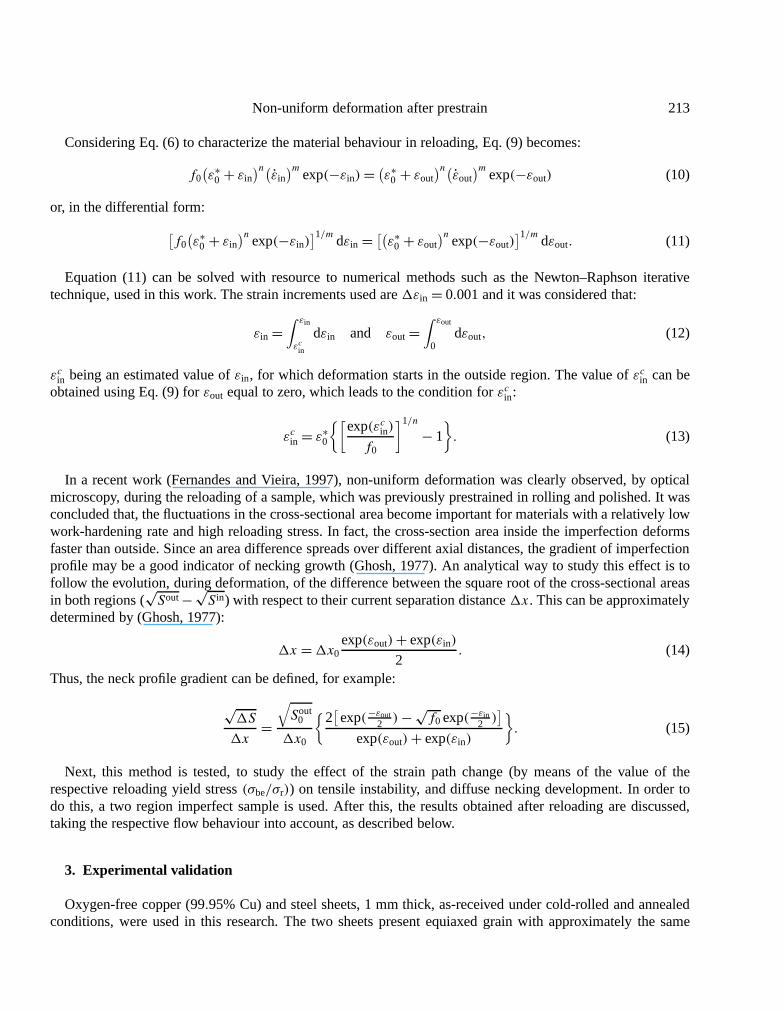
The results are shown infigure 3, consideringεin as a function ofεout. Whatever the value of the imperfectionparametera = 0.25, 0.50 or 1.00 mm (f0= 0.96, 0.92 and 0.84, respectively), the strain gradient between thetwo regions increases during deformation. Infigure 3, the results of numerical computation are also shown.Based on Eq. (11), they allow comparison with the experimental results. The numerical computation results areconsidered in two cases: takingm= 0 and in the case ofm= 0.012, as indicated for steel and copper. The casem= 0.012 shows perfect agreement with the experimental results. The strain-rate hardening exponentm, hasan effect of slowing the growth rate of the imperfection, as was argued by Ghosh (1977). For this reason, weconsider the following value ofm as always being equal to 0.012, for both materials, which corresponds to theexperimental values usually indicated (Barata da Rocha et al., 1985; Gracio et al., 1987).
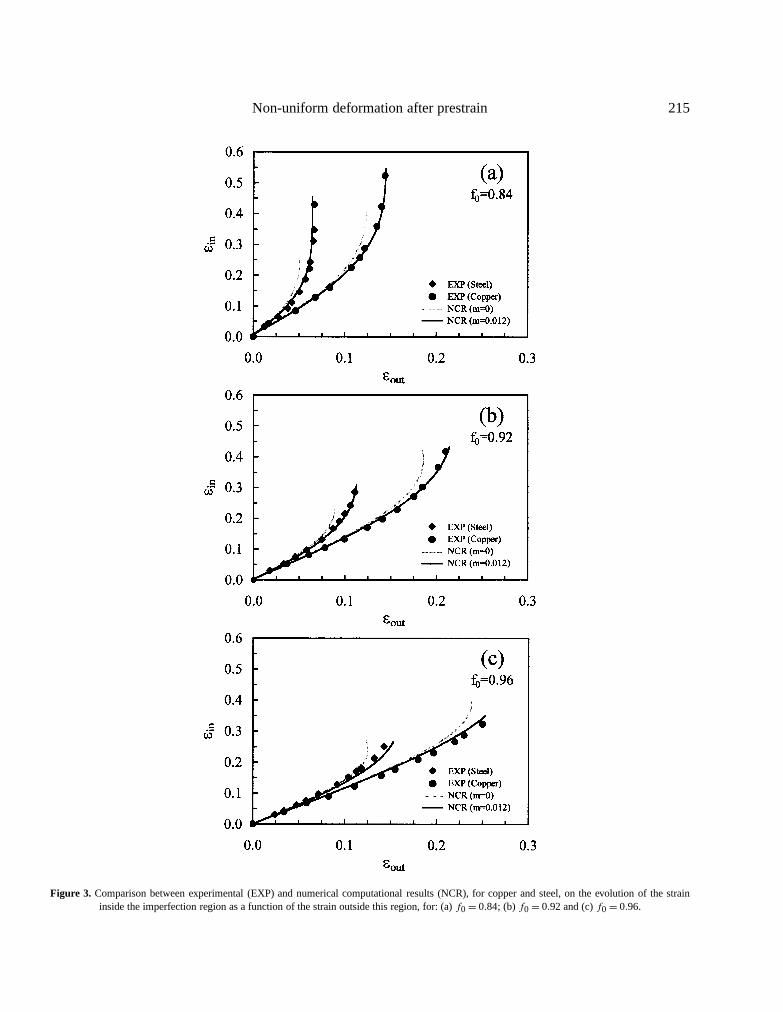
In figure 4, the numerical computation results for the cases off0 = 0.995, 0.990, 0.985, and 0.980 areshown. These cases are allowed by standardisation (the last one being near the allowable limit). The caseof f0 = 0.96 is also considered, in order to show a case for which experimental results have been obtained(for f0 lower than 0.96, the experimental measurement of the dimensions of the sample becomes relativelyinexact; this is the reason why these cases were not experimentally considered). In all cases, the profilegradient(
√1S/1x) develops slowly, at the beginning, and increases with deformation. The imperfection
Non-uniform deformation after prestrain 215
Figure 3. Comparison between experimental (EXP) and numerical computational results (NCR), for copper and steel, on the evolution of the straininside the imperfection region as a function of the strain outside this region, for: (a)f0= 0.84; (b)f0= 0.92 and (c)f0= 0.96.
216 J.-V. Fernandes et al.
Figure 4. Numerical computational results showing the strain within the imperfection and the necking profile gradient, as functions of strain outside
imperfection. The necking profile gradient is normalised with respect to the initial gradient: NPG= (√Sout/1x)/(√Sout
0 /1x0). The size of theimperfection isf0= 0.995,f0= 0.990,f0= 0.985,f0= 0.980 andf0= 0.960. Both materials are considered: (a) copper and (b) steel.
growth kinetics are influenced by the values ofn andf0. The increasing value of the strain-hardening exponent,n, and the increasing value off0 also slow the spread of the imperfection.
The above results show that, the strain value attained in the outside region is dependent on the imperfectionsize. We believe that in most of the cases, the tensile samples present imperfections withf0 = 0.99. In fact,this value represents approximately half of the imperfection allowed by standardisation. Moreover, in general,the uniform strain obtained by tension is close to the value of the hardening coefficientn, at least for low

Non-uniform deformation after prestrain 217
strain rates (usually used for classical tensile tests). Or, in the case off0= 0.99, the strain in the region outsidethe imperfection has approximately the same maximum strain value as the hardening coefficientn, for bothmaterials (maximumε0 equal to 0.39 for copper (n= 0.41) and 0.24 to steel (n= 0.25)). So,f0= 0.99 mustbe representative of most cases of tensile tests and it will be always considered in the following discussion.
4. Flow localisation in prestrained materials
In tension, the phenomenon of flow localisation is recognised as a precursor to failure. During complex strainpaths, an early flow localisation is often observed ((Vieira et al., 1990; Schmitt et al., 1991; Fernandes et al.,1993) for example). In this context, it is useful to emphasise the correlation between the hardening behaviourand the strain distribution along the subsequent path. The effect of the strain path change can be analysedby means of the parameter(σbe/σr). This parameter characterises the strain path change:(σbe/σr) = 1 whenthere is no strain path change and its value can attain 1.12 or even 1.15 for the harder strain path change as,for example, in tension normal to previous rolling (Fernandes and Vieira, 1997). Latent hardening effects canexplain the behaviour in reloading, particularly, the range of values of(σbe/σr). In fact, the differences betweenmonotonic and subsequent work-hardening behaviour are related to different microstructural evolutions at thebeginning of reloading. These are dependent on the prestrain mode and path change. Microstructural analysesduring reloading confirmed this point (Schmitt et al., 1991).
The present study concerns copper and steel sheets, whose flow behaviour laws are described in the formerparagraph (n= 0.41 for copper andn= 0.25 for steel;m is considered equal to 0.012 for both materials). TheSwift equation (Eq. (1)) describes the behaviour in simples strain path, and the Eq. (6) describes the behaviourin reloading. The numerical computation method proposed by Ghosh (1977) was adapted for the present case(Eq. (10) to (15)), as has been described above.
In figures 5and6 numerical computational results show the evolution of the strain within the imperfection,and the necking profile gradient. These are demonstrated as functions of strain outside imperfection, duringdeformation in reloading, for different(σbe/σr) values. For both materials, copper (figure 5) and steel (figure 6),two prestrain values are presented. For the low prestrain values, the curves are not significantly influenced bythe (σbe/σr) value. When the prestrain is higher (at about half the value ofn), the prestrain value stronglyinfluences the evolution of the strain within the imperfection and the necking profile gradient.
A final exercise, shown infigures 7and8, explains the conjoint effect of prestrain and strain path changeon strain localisation in reloading. This is evaluated by the residual strain defined by (i) the maximum strainattainned in the outside regionεres
out, and (ii) the strain inside the imperfection region up to unstable flowεresin ,
such that the critical value dεout/dεin is chosen equal to 0.1. Both figures show the evolution of the residualstrain as a function of(σbe/σr), for six cases of prestrain values. For low prestrain values (εp up to 0.06, forcopper, and 0.03, for steel) a homogeneous deformation is observed in the tensile sample, when a large amountof strain is being applied. This effect is only slightly dependent on the strain path change through the valueof (σbe/σr). For higher prestrain values rapid strain localisation within the imperfection is often observed.Finally, the comparison between both materials allows us to conclude that the imperfection growth kinetics inprestrained samples is highly influenced by the work-hardening parametern.
5. Conclusion
A simplified analysis was used to model the behaviour in tension of a metallic specimen, with a geometricalimperfection. The flow behaviour is described by a Swift law equation including strain-rate sensitivity. A

218 J.-V. Fernandes et al.
Figure 5. Numerical computational results showing the strain within the imperfection and the necking profile gradient, as functions of strainoutside imperfection, during the deformation of copper. The necking profile gradient is normalised with respect to the initial gradient: NPG=(√Sout/1x)/(
√Sout
0 /1x0). The size of the imperfection isf0= 0.99 and the change of strain path is such that: (a)εp= 0.03 and (b)εp= 0.18.
modified law was used for prestrained materials, which incorporate the plastic prestrain value adjusted tothe path change. Experimental results obtained in simple tension of samples with large imperfection and inprestrained samples with imperfections as allowed by standardisation, were used to validate the method used.The main study concerns the combined effects of the strain-hardening exponent, the prestrain value and thetype of path change. In this context, the following conclusion can be drawn:

Non-uniform deformation after prestrain 219
Figure 6. Numerical computational results showing the strain within the imperfection and the necking profile gradient, as functions of strainoutside imperfection, during the deformation of steel. The necking profile gradient is normalised with respect to the initial gradient: NPG=(√Sout/1x)/(
√Sout
0 /1x0). The size of the imperfection isf0= 0.99 and the change of strain path is such that: (a)εp= 0.02 and (b)εp= 0.08.
– The evolution of the strain in both zones of the sample and the strain saturation in the region outsidethe imperfection due to the onset of necking, can be well predicted by the model, as was experimentallyconfirmed.
– The model predicts that the imperfection growth kinetics is influenced by the strain hardening exponentn,obtained in simple strain path. The spread of the imperfection slows down with increasingn values, evenafter path change.

220 J.-V. Fernandes et al.
Figure 7. Evolution of the residual strain in the outside region(εresout), in the reloading of copper, with the parameter(σbe/σr), for different cases of
prestrain values:εp = 0.06, 0.12, 0.18, 0.24 and 0.30. For the same cases, the evolution of the residual strain inside the imperfection region up tounstable flow(εres
in ) is also shown. This is defined by the critical value dεout/dεin chosen equal to 0.1.
Figure 8. Evolution of the residual strain in the outside region(εresout), in reloading of steel, with the parameter(σbe/σr), for different cases of the
prestrain values:εp= 0.03, 0.06, 0.09, 0.12, 0.15 and 0.18. For the same cases, the evolution of the residual strain inside the imperfection region up tounstable flow(εres
in ) is also shown. This is defined by the critical value dεout/dεin chosen equal to 0.1.

Non-uniform deformation after prestrain 221
– For low prestrain values (less thann/3) the strain path change has a minor effect on strain localisation. Inthis case, a homogeneous deformation is always observed in the tensile sample, when a large amount ofstrain is being applied. For higher prestrain values, the strain distribution behaviour is quite dependent onthe value(σbe/σr) and therefore, on the strain path change.
Acknowledgement
The authors are indebted to the Portuguese Science and Technology Foundation and Program PRAXIS XXI,for financial support.
References
Barata da Rocha A., Barlat F., Jalinier J.M., 1985. Prediction of the forming limit diagrams of anisotropic sheets in linear and non-linear loading.Mater. Sci. Eng. 68, 151–164.
Chung K., Wagoner R.H., 1986. Effect of stress-strain-law transients on formability, Metall. Trans. A 17, 1001–1009.Esche S.K., Shivpuri R., 1998. A consistent criterion for diffuse necking in sheet metals using Hill’s 1979 yield surface. J. Eng. Mater. Technol. 120,
177–182.Fernandes J.V., Gracio J.J., Schmitt J.-H, 1993. Grain size effect on the microstructural evolution of copper deformed in rolling-tension.
In: C. Teodosiu, J.L. Raphanel and F. Sidoroff (Eds), Large Plastic Deformations: Fundamental Aspects and Applications to Metal Forming, A.A.Balkema, Rotterdam, pp. 219–228.
Fernandes J.V., Vieira M.F., 1997. Strain distribution in copper tensile specimens prestrained in rolling. Metall. Mater. Trans. A 28, 1169–1179.Fernandes J.V., Rodrigues D.M., Menezes L.F., Vieira M.F., 1998. A modified Swift law for prestrained materials. Int. J. Plasticity 14, 537–550.Ghosh A.K., Backofen W.A., 1973. Strain hardening and instability in biaxially streched sheets. Metall. Trans. 4, 1113–1123.Ghosh A.K., 1977. Tensile instability and necking in materials with strain hardening and strain-rate hardening. Acta Metall. 25, 1413–1424.Ghosh A.K., 1980. A physically-based constitutive model for metal deformation. Acta Metall. 28, 1443–1465.Gracio J.J., Fernandes J.V., Barata da Rocha A., 1987. Theoretical prediction of the limit curves for simulation of plastic instability. In: M. Predeleanu
(Ed.), Computational Methods for Predicting Material Processing Defects, Elsevier, Amsterdam, pp. 161–170.Hart E.W., 1970. A phenomelological theory for plastic deformation of polycrystalline metals. Acta Metall. 18, 599–610.Hutchinson J.W., Neale K.W., 1977. Influence of strain-rate sensitivity on necking under uniaxial tension. Acta Metall. 25, 839–846.Jonas J.J., Baudelet B., 1977. Effect of crack and cavity generation on tensile stability. Acta Metall. 25, 43–50.Lian J., Baudelet B., 1986. Necking development and strain to fracture under uniaxial tension. Mater. Sci. Eng. 84, 157–162.Lin I.-H., Hirth J.P., Hart E.W., 1981. Plastic instability in uniaxial tension tests. Acta Metall. 29, 819–827.Menezes L.F., Fernandes J.V., Rodrigues D.M., 1999. Numerical simulation of tensile tests of prestrained sheets. Mater. Sci. Eng. A 264, 130–138.Miles J.P., 1975. The initiation of necking in rectangular elastic/plastic specimens under uniaxial and biaxial tension. J. Mech. Phys. Solids 23,
197–213.Raphanel J.L., Schmitt J.-H., Baudelet B., 1986. Effect of a prestrain on the subsequent yielding of a low carbon steel sheets: experiments and
simulations. Int. J. Plast. 2, 371–378.Rees D.W.A., 1994. Equivalence and instability correlations for isotropic and anisotropic sheet plasticity. J. Mater. Process. Technol. 40, 173–194.Schmitt J.-H., Fernandes J.V., Gracio J.J., Vieira M.F., 1991. Plastic behaviour of copper sheets during sequential tension tests. Mater. Sci. Eng.A
147, 143–154.Swift H.W., 1952. Plastic instability under plane stress. J. Mech. Phys. Solids 1, 1–18.Tvergaard V., 1993. Necking in tensile bars with rectangular cross-section. Comp. Meth. in Appl. Mech. and Engn. 103, 273–290.Vieira M.F., Schmitt J.-H., Gracio J.J., Fernandes J.V., 1990. The effect of strain path change on the mechanical behaviour of copper sheets. J. Mater.
Process. Technol. 24, 313–322.Wagoner R.H., Laukonis J.V., 1983. Plastic behaviour of aluminium-killed steel following plane-strain deformation. Metall. Trans. A 14, 1487–1495.Zandrahimi M., Platias S., Price D., Barret D., Bate P.S., Roberts W.T., Wilson D.V., 1989. Effects of change in strain path on work hardening in
cubic metals. Metall. Trans. A 20, 2471–2482.