Investigation of fluoride incorporation within gelatin/calcium phosphate nanocomposite scaffold...
7
106 Advanced Composites Letters, Vol. 22, Iss. 5, 2013 1. INTRODUCTION Scaffolds for bone tissue engineering should be three-dimensional(3D) and mimic the structure and biological function of the extracellular matrix (ECM)[1]. Different techniques such as progen leaching [2], phase separation [3], solvent casting and freeze drying [4, 5, 6] have been used to fabri- cate porous 3D scaffold. Natural polymers such as collagen, gelatin, and min- eral compounds like Hydroxylapatite have been used as biomimetics to fabricate bone scaffolds through biomimetic approaches. The formation and struc- ture of these chemical compounds is of great impor- tance and should come close to bone material while designing bone biomimetics. Most biomimetic syn- thetic processes occur at physiological conditions (pH value of 7.4 and a temperature of 37 °C) [7-10] that are utmost similar to those of the human body. Some studies even have tried to mimic the condition more closely to body’s biological environment. Dif- fusion-based methods [11-13] and electrophoresis [14] are processes that have been performed under physiological conditions. Diffusion of calcium and phosphate ions into a gel-like matrix closely mimics the process of bone formation in the body, as the gel simulates the cartilaginous precursor template. Letter In the body, ions move to the bone formation area through the vessels’ walls and the extracellular ma- trix to enter the preliminary cartilage via diffusion. The mineral phase formed within the gel nucleates and grows on the polymer chains, resulting to an ideal combination with the matrix. The composites formed under these conditions are very similar to natural bone and its mineralized phase works as a particulate reinforcing phase. Hydroxyapatite (HA, Ca 10 (PO 4 ) 6 (OH) 2 ) and fluor- apatite (FA, Ca 10 (PO 4 ) 6 F 2 ) are two important mem- bers of calcium phosphate(CaP) family with a crys- tallographic structure similar to calcified tissues of vertebrates and in various reports have been used as raw materials for preparing scaffold in bone tissue engineering[4, 5,15]. Fluoride is a vital trace element needed for normal dental and skeletal formation and ontogeny [16]. F− ion is known to stimulate osteoblast activity both in vitro and in vivo. In addition, the mineral phase of tooth enamel consists of apatite containing 0.04 wt. % to 0.07 wt. % of fluoride. It has been suggested that a fluoride intake of about 1.5–4 mg/day reduces the risk of dental caries dra- matically [17]. A large number of studies [17-29] INVESTIGATION OF FLUORINE INCORPORATION WITHIN GELATIN/CAL- CIUM PHOSPHATE NANOCOMPOSITE SCAFFOLD PREPARED THROUGH A DIFFUSION METHOD Nafiseh Baheiraei, Mahmoud Azami * Department of Tissue Engineering, School of Advanced Technologies in medicine, Tehran University of Medical Sciences, 1417755469 Tehran, Iran. *Author to whom corresponding should be addressed Tel.: (98-21) 8899-1116; Fax: (98-21) 8899-1117; e-mail:[email protected] Received 21 June 2013; accepted 30 July 2013 ABSTRACT In this study diffusional method was used to prepare a biomimetic calcium phosphate/gelatin nanocomposite as a scaffold for bone and tooth tissue engineering. Incorporation of fluorine into mineral phase of the scaf- fold was also investigated. Addition of fluoride to the synthesis process caused formation of fluoroapatite and calcium fluoride along with hydroxyapatite within gelatin while in the sample lacking fluorine atoms, hydroxy- apatite and octacalcium phosphate were detected. With addition of fluorine within the structure of precipitated minerals, morphology of minerals was dramatically changed from oriented rod-like minerals with rectangular cross section toward spherical particles consisting of smaller crystals with uneven surface scattered over the gelatinous bulk material. Keywords: Biomimetic, Diffusion, scaffold, Tissue engineering, Calcium phosphate
Transcript of Investigation of fluoride incorporation within gelatin/calcium phosphate nanocomposite scaffold...

106 Advanced Composites Letters, Vol. 22, Iss. 5, 2013
1. INTRODUCTIONScaffolds for bone tissue engineering should be three-dimensional(3D) and mimic the structure and biological function of the extracellular matrix (ECM)[1]. Different techniques such as progen leaching [2], phase separation [3], solvent casting and freeze drying [4, 5, 6] have been used to fabri-cate porous 3D scaffold.
Natural polymers such as collagen, gelatin, and min-eral compounds like Hydroxylapatite have been used as biomimetics to fabricate bone scaffolds through biomimetic approaches. The formation and struc-ture of these chemical compounds is of great impor-tance and should come close to bone material while designing bone biomimetics. Most biomimetic syn-thetic processes occur at physiological conditions (pH value of 7.4 and a temperature of 37 °C) [7-10] that are utmost similar to those of the human body. Some studies even have tried to mimic the condition more closely to body’s biological environment. Dif-fusion-based methods [11-13] and electrophoresis [14] are processes that have been performed under physiological conditions. Diffusion of calcium and phosphate ions into a gel-like matrix closely mimics the process of bone formation in the body, as the gel simulates the cartilaginous precursor template.
Letter
In the body, ions move to the bone formation area through the vessels’ walls and the extracellular ma-trix to enter the preliminary cartilage via diffusion. The mineral phase formed within the gel nucleates and grows on the polymer chains, resulting to an ideal combination with the matrix. The composites formed under these conditions are very similar to natural bone and its mineralized phase works as a particulate reinforcing phase.
Hydroxyapatite (HA, Ca10(PO4)6(OH)2) and fluor-apatite (FA, Ca10(PO4)6F2) are two important mem-bers of calcium phosphate(CaP) family with a crys-tallographic structure similar to calcified tissues of vertebrates and in various reports have been used as raw materials for preparing scaffold in bone tissue engineering[4, 5,15].
Fluoride is a vital trace element needed for normal dental and skeletal formation and ontogeny [16]. F− ion is known to stimulate osteoblast activity both in vitro and in vivo. In addition, the mineral phase of tooth enamel consists of apatite containing 0.04 wt. % to 0.07 wt. % of fluoride. It has been suggested that a fluoride intake of about 1.5–4 mg/day reduces the risk of dental caries dra-matically [17]. A large number of studies [17-29]
INVESTIGATION OF FLUORINE INCORPORATION WITHIN GELATIN/CAL-CIUM PHOSPHATE NANOCOMPOSITE SCAFFOLD PREPARED THROUGH
A DIFFUSION METHOD
Nafiseh Baheiraei, Mahmoud Azami *
Department of Tissue Engineering, School of Advanced Technologies in medicine,Tehran University of Medical Sciences, 1417755469 Tehran, Iran.
*Author to whom corresponding should be addressedTel.: (98-21) 8899-1116; Fax: (98-21) 8899-1117; e-mail:[email protected]
Received 21 June 2013; accepted 30 July 2013
ABSTRACTIn this study diffusional method was used to prepare a biomimetic calcium phosphate/gelatin nanocomposite as a scaffold for bone and tooth tissue engineering. Incorporation of fluorine into mineral phase of the scaf-fold was also investigated. Addition of fluoride to the synthesis process caused formation of fluoroapatite and calcium fluoride along with hydroxyapatite within gelatin while in the sample lacking fluorine atoms, hydroxy-apatite and octacalcium phosphate were detected. With addition of fluorine within the structure of precipitated minerals, morphology of minerals was dramatically changed from oriented rod-like minerals with rectangular cross section toward spherical particles consisting of smaller crystals with uneven surface scattered over the gelatinous bulk material.
Keywords: Biomimetic, Diffusion, scaffold, Tissue engineering, Calcium phosphate

Advanced Composites Letters, Vol. 22, Iss. 5, 2013 107
have been performed to support the fact that fluoride can be regarded for prevention of dental caries and treatment of osteoporosis.Considering the therapeutic advantages of Fluoride, this study purposed to examine the incorporation of F ion into mineral phase of nanocomposite gelatin (GEL)/CaP scaffold using a diffusional method. In order to do that, fluorine was added during synthesis process to be incorporated in the structure of cal-cium phosphates precipitates.
2. MATERIALS AND METHODS2.1. Scaffold fabricationScaffolds were prepared by making an aqueous solution of 10% (w/v) gelatin (Merck, microbiol-ogy grade, catalogue number 104070) with calcium chloride (0.6 M) (Merck, catalogue number 2380). Disodium hydroxide phosphate (1 M) (Merck, cata-logue number 106573) solution was also prepared and the pH of both solutions were brought to about 7.4 using Hydroxymethylaminomethane(Tris) (Merck, catalogue number 8382) and hydrochloric acid (HCl) (Merck, catalogue number 280211).
In the next step, the Calcium containing GEL so-lution was poured into a cylindrical mold and kept at 4°C for 2 hours until physical gelation occurred. The prepared gel was mineralized through incuba-tion at 4°C for 48 hours following soaking into the phosphate containing solution named S1.To incorpo-rate F ion within the prepared gel, part of the Phos-phate (PO4) containing solution was replaced with ammonium fluoride (NH4F) (Merck,catalogue num-ber 1011640) in different fractions of 25%,50% and
75% of total volume, namely S2-S4 respectively. After diffusion of ions into the gel, a white precipi-tate formed within the gel in a gradient manner from the border to the center of gel (Fig1).
The mineralized gels were then extracted and freeze dried to make a porous structure through solvent sublimation. Scaffolds were cross linked by incuba-tion in a 1% glutaraldehyde (GA) (Merck, Catalogue number 820603) solution for 24 hours and then were washed with deionized water to remove the rem-nants of the GA. For some of the characterization methods, the samples were chopped and milled to get a fine powder from prepared scaffolds. The as-prepared compositions are introduced in Table1.
2.2. Characterization Fourier transform infrared spectroscopy (FT-IR, Bomem MB 100) was carried out in the range of 500 to 4000 cm-1 at a scan speed of 23 scan/min with 4 cm-1 resolution in KBr-diluted medium to analyze the formation of calcium and magnesium phosphate within the scaffold.
To analyze the crystallographic properties of the scaffold powder,X-ray diffraction (XRD) patterns were obtained by means of a Siemens-Brucker D5000 diffractometer . Cu-Kα radiation was used (40 mA, 40 kV) and the 2θ range was from 3 to 60° at a scan speed of 2°/min. Crystallographic identifi-cation of the phases in synthesized powder was ex-amined by comparing experimental XRD patterns to standards compiled by the International Center for Diffraction Data (ICDD). The average size of in-dividual crystallites was calculated from XRD data using the Scherrer approximation (Equation 1):
(1)
Where t is the crystallite size, λ is the wavelength of Cu-Kα radiation (1.540560 Å), and β1/2 is the full width at half-maximum intensity.
To determine the level of incorporation of each added element in the final precipitates formed within hydrogel, bulk elemental analysis of Ca, P Fig.1: schematic representation of mineralization pro-
cess.
9
Table 1:Results obtained from elemental chemical analysis along with samples composition applied in this research.
Table 2: Infrared assigned and chemical relevant bonds in prepared gelatin/calcium phosphate nanocomposites.
Infrared frequency (cm-1) Assignment Compound 567, 605 PO4
-3 bend ν4 Precipitate(HA/FA) 630 OH- Precipitate(HA)
1030-1060 PO4-3 bend ν3 Precipitate(HA/FA)
~1240 N-H GEL (Amide III) ~1340 Ca-COO GEL-precipitate(HA/FA) 1456 COO GEL
~1540 N-H bend GEL (Amide II) ~1652 C=O stretch GEL (Amide I) ~2930 C-H GEL (Amide B) ~3070 C-H stretch GEL (Amide B) ~3425 OH Stretch Humidity
Figure captions:
Fig.1: schematic representation of mineralization process. Fig.2: XRD diffractogram of the synthesized precipitate for the sample, a) lacking F, b) with 25%, c) with 50% and,
d) with 75% substitution of PO4 by F during synthesis. Fig. 3: FTIR spectrum of the mineralized GEL for the sample lacking F along with the sample with 50%
substitution of PO4 by F. Fig. 4: SEM micrograph of obtained from GEL/CaP nanocomposite for the sample lacking F, a) porous structure of the nanocomposite scaffold, b) colonies of needle like formed minerals on the surface of a pore wall, c and d) higher
magnification of the precipitated needles. Fig. 5: SEM micrograph of precipitates formed on the surface of GEL/CaP nanocomposite for the sample containing
F, a and b) for 25%, c and d) for 50% and e & f) for 75% substitution of PO4 by F during synthesis.
Sample Composition/No
Applied in synthesis Precipitated mineral F Substitution%
Mineral precipitaed (P+F) /Ca
Mol ratio P /Ca
Mol ratio F/Ca
Mol ratio P/F
Mol ratio (P+F) /Ca Mol ratio
P/Ca Mol ratio
F/Ca Mol ratio
P/F Mol ratio
Without F S1 0.6 0.60 0 - 0.61 0.61 0 - --- OCP, HA
F substitution
S2 0.6 0.45 0.15 3 0.54 0.39 0.15 2.6 100 HA, FA S3 0.6 0.30 0.30 1 0.36 0.11 0.25 0.44 60 HA, FA S4 0.6 0.15 0.45 0.33 0.36 0.05 0.36 0.14 58 HA, FA, CaF2
Table 1:Results obtained from elemental chemical analysis along with samples composition applied in this research.
3
was used (40 mA, 40 kV) and the 2θ range was from 3 to 60° at a scan speed of 2°/min. Crystallographic identification of the phases in synthesized powder was examined by comparing experimental XRD patterns to standards compiled by the International Center for Diffraction Data (ICDD). The average size of individual crystallites was calculated from XRD data using the Scherrer approximation (Equation 1):
1/2
0.9cos
t
(1)
Where t is the crystallite size, λ is the wavelength of Cu-Kα radiation (1.540560 Å), and β1/2 is the full width at half-maximum intensity. To determine the level of incorporation of each added element in the final precipitates formed within hydrogel, bulk elemental analysis of Ca, P and F was performed. For this aim, atomic absorption technique (AA-6800, Seris, Shimadzu, Japan), emission spectroscopy(Jarrell-Ash 3.4, USA) and potentiometry were used respectively. Pore size estimation and morphological investigation of the nanocomposites were performed using a XL30 scanning electron microscope (SEM). The samples were sputter-coated with gold before examination. Higher magnified images were taken to compare morphology of the precipitated minerals within gelatin hydrogel for different samples. 3. RESULTS AND DISCUSSION White precipitates were resulted by diffusion of Ca+2 from peripheral solution into the PO4
3-(or F) containing hydrogel. XRD was used to analyze the crystallographic properties of the precipitated phase within the GEL matrix. Figure 2 presents the diffractogram of samples containing fluorine compared to the one without fluorine. As evidenced in Figure 2(a), the diffractogram pertaining to the sample without fluorine has clearly defined peaks, indicating its relatively crystalline nature. As is marked in Figure 2(a), the peaks obtained from this sample mostly pertain to hydroxyapatite and OCP according to ICCD database. Graphs 2(b), 2(c), and 2(d) pertain to samples with 25%(S2), 50%( S3) and 75% (S4) fluoride replacement with phosphate during synthesis, respectively. It can be seen that addition of fluorine during synthesis process has caused the relatively crystalline structure of the initial sample to shift towards an amorphous compound. The peaks appearing in the diffractogram all pertain to HA and FA. In other words, addition of fluorine to the sample lacking fluorine changes its OCP and HA to HA and FA. The average size of individual crystallites was estimated to be between 40-80 nm using the Scherrer approximation. Fig. 3 shows the FTIR spectra of the scaffolds with different precipitates including those without F (graph a) and those with 50% F additional ratio in synthesis procedure (graph b). Detected chemical bonds with related wave numbers are also shown in Table 2. Most of the peaks appearing in these spectra were almost identical. Apart from the typical peaks for GEL (1240, 1456, 1540, 1652, 2930 and 3070 cm-1), other peaks (at about 567, 605, 630, 870, 1040 and 1400 cm-1) are due to mineral phase formed within GEL including HA, octacalcium phosphate (OCP) and FA. In addition, a peak appeared at approximately 1340 cm-1 corresponds to a chemical bond
Investigation of Fluorine Incorporation Within Gelatn/Calcium Phosphate Nanocomposite Scaffold Prepared Through a Diffusion Method
108 Advanced Composites Letters, Vol. 22, Iss. 5, 2013
Nafiseh Baheiraei, Mahmoud Azami
and F was performed. For this aim, atomic absorp-tion technique (AA-6800, Seris, Shimadzu, Japan), emission spectroscopy(Jarrell-Ash 3.4, USA) and potentiometry were used respectively.
Pore size estimation and morphological investiga-tion of the nanocomposites were performed using a XL30 scanning electron microscope (SEM). The samples were sputter-coated with gold before ex-amination. Higher magnified images were taken to compare morphology of the precipitated minerals within gelatin hydrogel for different samples.
3. RESULTS AND DISCUSSIONWhite precipitates were resulted by diffusion of Ca+2 from peripheral solution into the PO4
3-(or F) containing hydrogel.
XRD was used to analyze the crystallographic prop-erties of the precipitated phase within the GEL ma-trix. Figure 2 presents the diffractogram of samples containing fluorine compared to the one without fluorine. As evidenced in Figure 2(a), the diffrac-togram pertaining to the sample without fluorine has clearly defined peaks, indicating its relatively crystalline nature. As is marked in Figure 2(a), the peaks obtained from this sample mostly pertain to hydroxyapatite and OCP according to ICCD data-base. Graphs 2(b), 2(c), and 2(d) pertain to samples with 25%(S2), 50%( S3) and 75% (S4) fluoride re-placement with phosphate during synthesis, respec-tively. It can be seen that addition of fluorine during synthesis process has caused the relatively crystal-line structure of the initial sample to shift towards an amorphous compound. The peaks appearing in the diffractogram all pertain to HA and FA. In other words, addition of fluorine to the sample lacking flu-orine changes its OCP and HA to HA and FA. The
Fig.2: XRD diffractogram of the synthesized precipi-tate for the sample, a) lacking F, b) with 25%, c) with 50% and, d) with 75% substitution of PO4 by F during
synthesis.
average size of individual crystallites was estimated to be between 40-80 nm using the Scherrer approxi-mation.
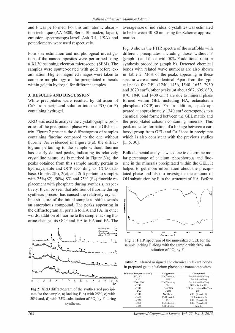
Fig. 3 shows the FTIR spectra of the scaffolds with different precipitates including those without F (graph a) and those with 50% F additional ratio in synthesis procedure (graph b). Detected chemical bonds with related wave numbers are also shown in Table 2. Most of the peaks appearing in these spectra were almost identical. Apart from the typi-cal peaks for GEL (1240, 1456, 1540, 1652, 2930 and 3070 cm-1), other peaks (at about 567, 605, 630, 870, 1040 and 1400 cm-1) are due to mineral phase formed within GEL including HA, octacalcium phosphate (OCP) and FA. In addition, a peak ap-peared at approximately 1340 cm-1 corresponds to a chemical bond formed between the GEL matrix and the precipitated calcium containing minerals. This peak indicates formation of a linkage between a car-boxyl group from GEL and Ca+2 ions in precipitate which is also consistent with the previous studies [5, 6, 30].
Bulk elemental analysis was done to determine mo-lar percentage of calcium, phosphorous and fluo-rine in the minerals precipitated within the GEL. It helped to get more information about the precipi-tated phase and also to investigate the amount of OH substitution by F in the structure of HA. Before
Fig. 3: FTIR spectrum of the mineralized GEL for the sample lacking F along with the sample with 50% sub-
stitution of PO4 by F.
9
Table 1:Results obtained from elemental chemical analysis along with samples composition applied in this research.
Table 2: Infrared assigned and chemical relevant bonds in prepared gelatin/calcium phosphate nanocomposites.
Infrared frequency (cm-1) Assignment Compound 567, 605 PO4
-3 bend ν4 Precipitate(HA/FA) 630 OH- Precipitate(HA)
1030-1060 PO4-3 bend ν3 Precipitate(HA/FA)
~1240 N-H GEL (Amide III) ~1340 Ca-COO GEL-precipitate(HA/FA) 1456 COO GEL
~1540 N-H bend GEL (Amide II) ~1652 C=O stretch GEL (Amide I) ~2930 C-H GEL (Amide B) ~3070 C-H stretch GEL (Amide B) ~3425 OH Stretch Humidity
Figure captions:
Fig.1: schematic representation of mineralization process. Fig.2: XRD diffractogram of the synthesized precipitate for the sample, a) lacking F, b) with 25%, c) with 50% and,
d) with 75% substitution of PO4 by F during synthesis. Fig. 3: FTIR spectrum of the mineralized GEL for the sample lacking F along with the sample with 50%
substitution of PO4 by F. Fig. 4: SEM micrograph of obtained from GEL/CaP nanocomposite for the sample lacking F, a) porous structure of the nanocomposite scaffold, b) colonies of needle like formed minerals on the surface of a pore wall, c and d) higher
magnification of the precipitated needles. Fig. 5: SEM micrograph of precipitates formed on the surface of GEL/CaP nanocomposite for the sample containing
F, a and b) for 25%, c and d) for 50% and e & f) for 75% substitution of PO4 by F during synthesis.
Sample Composition/No
Applied in synthesis Precipitated mineral F Substitution%
Mineral precipitaed (P+F) /Ca
Mol ratio P /Ca
Mol ratio F/Ca
Mol ratio P/F
Mol ratio (P+F) /Ca Mol ratio
P/Ca Mol ratio
F/Ca Mol ratio
P/F Mol ratio
Without F S1 0.6 0.60 0 - 0.61 0.61 0 - --- OCP, HA
F substitution
S2 0.6 0.45 0.15 3 0.54 0.39 0.15 2.6 100 HA, FA S3 0.6 0.30 0.30 1 0.36 0.11 0.25 0.44 60 HA, FA S4 0.6 0.15 0.45 0.33 0.36 0.05 0.36 0.14 58 HA, FA, CaF2
Table 2: Infrared assigned and chemical relevant bonds in prepared gelatin/calcium phosphate nanocomposites.

Advanced Composites Letters, Vol. 22, Iss. 5, 2013 109
the analysis, precipitates were washed to remove the remained unreacted ions trapped within the GEL. Obtained results can be seen in Table 1. In order to have a better comparison, atomic molar ratios in two situations including, before precipitation (applied in synthesis) and after precipitation were used. This especially helped us to determine the exact substitu-tion that has been occurred.
Since the results of XRD analysis indicates the pres-ence of FA and HA in the deposit phase, F/Ca ratio was used before and after sedimentation to evaluate the rate of F atom entering the sediment’s structure. The corresponding ratios for the three designed sam-ples of OH replacement with F atom in HA structure were 0.25, 0.50, and 0.75, respectively. Analysis of sediment revealed that the relevant ratios in the final deposit were 0.16, 0.25 and 0.36. Percent of sub-stitution was defined according to equation (2) and estimated for each case.
(2)
This finding indicates that in lower ratios of F addi-tion, all of the F atoms enter in the deposit structure. However, as the ratio rises, smaller amount pene-trates the final sediment. In addition, since the F/Ca ratio in the FA compound equals 0.2(stoichiometric ratio in the pure FA), it may be concluded that some other compound other than FA with higher F/Ca ratio must be present in the final sediment so that the final ratios appear true. Considering the type of reactants, the only other compound presumable is calcium fluoride (CaF2); this is consistent with the results of XRD analysis. In other words, with in-creasing amounts of added F, more CaF2 sediment is produced alongside HA and FA.
Fig. 4a shows SEM images of typical morphology of obtained scaffold. A network of interconnected pores with diameters ranging from 200 to 500 µm, which are optimal for bone cell growth, can be ob-served. Mineral nanocrystals being projected out of the pore surface walls and precipitated within hy-drogel could also be detected in the micrographs with higher magnification (Fig. 4b, c, d).
Samples containing only calcium and phosphate showed budding and crystal growth in the form of rod shaped crystals in closely packed, nearly spheri-cal 40-60 µm colonies on the surface. It could be noted that rod-shaped crystals have grown with rect-angular cross sections about 250 to 500 nm in thick-ness. As Figure 4c depicts, the rod shaped crystals growing quite separately, however, steric hindrance has resulted their tips moving further apart and thus diverging from one another during elongation. Con-sequently, the morphology of each colony is roughly spherical.
Samples in which fluorine ion was added along with phosphate yielded deposits with morphologies completely different. In all samples where fluorine ion was replaced by phosphate at 25%(Fig5a,b), 50%(Fig5c,d) and 75%(Fig5e,f) ratios during syn-thesis process, the deposits were nearly like spherical particles consisting of smaller crystals with uneven (rough) surface scattered over the gelatinous bulk material. This is an indication that adding fluorine influence crystal growth profoundly and prevents
4
formed between the GEL matrix and the precipitated calcium containing minerals. This peak indicates formation of a linkage between a carboxyl group from GEL and Ca+2 ions in precipitate which is also consistent with the previous studies [5, 6, 30]. Bulk elemental analysis was done to determine molar percentage of calcium, phosphorous and fluorine in the minerals precipitated within the GEL. It helped to get more information about the precipitated phase and also to investigate the amount of OH substitution by F in the structure of HA. Before the analysis, precipitates were washed to remove the remained unreacted ions trapped within the GEL. Obtained results can be seen in Table 1. In order to have a better comparison, atomic molar ratios in two situations including, before precipitation (applied in synthesis) and after precipitation were used. This especially helped us to determine the exact substitution that has been occurred. Since the results of XRD analysis indicates the presence of FA and HA in the deposit phase, F/Ca ratio was used before and after sedimentation to evaluate the rate of F atom entering the sediment’s structure. The corresponding ratios for the three designed samples of OH replacement with F atom in HA structure were 0.25, 0.50, and 0.75, respectively. Analysis of sediment revealed that the relevant ratios in the final deposit were 0.16, 0.25 and 0.36. Percent of substitution was defined according to equation (2) and estimated for each case.
(2)
This finding indicates that in lower ratios of F addition, all of the F atoms enter in the deposit structure. However, as the ratio rises, smaller amount penetrates the final sediment. In addition, since the F/Ca ratio in the FA compound equals 0.2(stoichiometric ratio in the pure FA), it may be concluded that some other compound other than FA with higher F/Ca ratio must be present in the final sediment so that the final ratios appear true. Considering the type of reactants, the only other compound presumable is calcium fluoride (CaF2); this is consistent with the results of XRD analysis. In other words, with increasing amounts of added F, more CaF2 sediment is produced alongside HA and FA. Fig. 4a shows SEM images of typical morphology of obtained scaffold. A network of interconnected pores with diameters ranging from 200 to 500 µm, which are optimal for bone cell growth, can be observed. Mineral nanocrystals being projected out of the pore surface walls and precipitated within hydrogel could also be detected in the micrographs with higher magnification (Fig. 4b, c, d). Samples containing only calcium and phosphate showed budding and crystal growth in the form of rod shaped crystals in closely packed, nearly spherical 40-60 µm colonies on the surface. It could be noted that rod-shaped crystals have grown with rectangular cross sections about 250 to 500 nm in thickness. As Figure 4c depicts, the rod shaped crystals growing quite separately, however, steric hindrance has resulted their tips moving further apart and thus diverging from one another during elongation. Consequently, the morphology of each colony is roughly spherical.
Fig. 4: SEM micrograph of obtained from GEL/CaP nanocomposite for the sample lacking F, a) porous struc-ture of the nanocomposite scaffold, b) colonies of needle like formed minerals on the surface of a pore wall, c and
d) higher magnification of the precipitated needles.
Fig. 5: SEM micrograph of precipitates formed on the surface of GEL/CaP nanocomposite for the sample con-taining F, a and b) for 25%, c and d) for 50% and e & f)
for 75% substitution of PO4 by F during synthesis.
Investigation of Fluorine Incorporation Within Gelatn/Calcium Phosphate Nanocomposite Scaffold Prepared Through a Diffusion Method

110 Advanced Composites Letters, Vol. 22, Iss. 5, 2013
Nafiseh Baheiraei, Mahmoud Azami
the formation of minerals with well-defined direc-tions or geometries.
Diffusional methods have been used to synthesize polymer/ HA(CaP) composite scaffold in many re-searches to mimic better bone structure[12-14, 31-35].
Eiden-Aßmann et al. investigated morphology of HA precipitated on different amino acid substrates through a double diffusion experiments. They con-cluded that, presence of the amino acids results in spheres with 2µm in diameter consisting of random-ly distributed needles, blades or plates depending on the reaction system. It was also shown that HA was only formed when the pH was around 7.4 or higher during reaction. A decrease in pH resulted in the transformation of HA to OCP [31].
Schwarz et al. investigated biomimetic crystalliza-tion of HA and FA by a double diffusion system in a porous poly(hydroxyacetic acid) (polyglycolide) matrix. They suggested that specific interactions between the growing aggregates and the polymeric matrix (nucleation and growth of crystals) occurred during their experiment. They observed that FA had elongated hexagonal prisms developing multi-ply branched edges that finally closed into spheres [32].
Busch et al. investigated biomimetic formation of fluoroapatite within gelatin hydrogel using a double diffusion method while an electric field was also ap-plied to the hydrogel perpendicular towards ions dif-fusion direction [33]. After one week, they observed fractal growth of anisotropic fluorapatite spheres with the diameter size of about 60 µm consisting of ordered hexagonal-prismatic crystals. Existence of electric field and diffusion based interaction be-tween ions was known to be the reason for this ob-servation [33].
In the non-diffusional experiments, reported results have shown more diversity. Liu et al. observed large amount of plate-like HA crystals with a width of about 2-5 micron and a thickness about 50 nm via soaking within a supersaturated calcified solution in the presence of hexadecylamine. They concluded that the HA crystals grow with the (0001) plane par-allel to the surface of the organic layer which leads to the formation of strip-like minerals [34].
In another research Hutchens et al fabricated a com-posite material consisting of calcium-deficient HA
deposited in a bacterial cellulose via alternating incubation in Ca and PO4 solution sources. SEM images confirmed that uniform solid spherical HA particles with a size of about 1µm like a network of nano-sized lamellar crystallites formed. They reported that orderly clusters become rough and ir-regular in shape as more HA was formed in the ma-trix.[35].
Our results and the previous reports highlight the fact that CaP minerals especially in HA and FA have natural tendency towards the formation of minerals in an ordered orientations and shapes. However, the condition of environment usually does not allow to the crystals to be grown orderly. Diffusion method provides a condition in which ions react with each other slowly, bringing more chance for atoms to be allocated in the particular crystallographic positions and thus form oriented crystals.
Our results also indicate that the addition of F into the structure destructs the growth of the precipitate within the hydrogel caused by diffusion process and affects the geometry of the crystals. This added ion has also a noticeable impact on the formation of more amorphous phase. Since addition of F to the synthesis was done with a ratio of F/Ca being more than 0.2, it is expectable that some other compounds with the F/Ca ratio more than 0.2 such as CaF2, will be precipitated. F/Ca ra-tios obtained from elemental analysis for precipitat-ed minerals are also in agreement with this fact.
4. CONCLUSIONSIn this study, addition of F atoms inside a Calcium phosphate ceramic phase within gelatin hydrogel was investigated using the diffusional method. For the sample with no F atoms, data obtained from various analyses revealed that the mineral formed within GEL has a low crystalline nature, consisting of HA and OCP. Results showed distinct change of precipitated phases after addition of F ions to the synthesis process. Addition of F to the synthesis process causes precipitation of FA and CaF2 along with HA within GEL.
Morphology of minerals for the sample without F was in the form of oriented nucleation and growth resulting in minerals with rod-like structure with rectangular cross section. From the morphological point of view, the major difference between our ob-servation and the reports published earlier was the detection of rod-like or needle-like CaP (or HA) minerals and the bigger size of mineral clusters.

Advanced Composites Letters, Vol. 22, Iss. 5, 2013 111
Investigation of Fluorine Incorporation Within Gelatn/Calcium Phosphate Nanocomposite Scaffold Prepared Through a Diffusion Method
Effect of F atoms substitution within precipitated minerals on the morphology of minerals was very intense and interesting. But in the F containing sam-ples, the deposits were nearly like spherical particles consisting of smaller crystals with uneven (rough) surface scattered over the gelatinous bulk mate-rial. The prepared porous nanocomposites could be considered as appropriate biomimetic scaffolds for skeletal and dental tissue engineering.
5. ACKNOWLEDGMENTSThis research has been supported by Tehran Uni-versity of Medical Sciences & health Services grant number 91-04-87-20188.
References:Subia, B., Kundu, J. and Kundu, S.C.,”Biomaterial scaf-fold fabrication techniques for potential tissue engineering applications”, Tissue Engineering ,(2010), 141.Mano, J.F., Silva, G. A., Azevedo ,H.S., Malafaya, P.B., Sousa, R.A., Silva, S.S., Boesel ,L.F., Oliviera, J.M., Santos, T.C., Marques, A.P., Neves, N.M. and Reis, R.L., “Natural origin biodegradable systems in tissue en-gineering and regenerative medicine: present status and some moving trends”, J R Soc Interface, 4/17 (2007), 999-1030.Pavia, FC., La Carrubba, V., Piccarolo, S., Brucato V.,” Polymeric scaffolds prepared via thermally induced phase separation: tuning of structure and morphology’, J Biomed Mater Res A, 86/2 (2008), 459-466.Azami ,M., Moztarzadeh, F. and Tahriri, M., “Prepara-tion, characterization and mechanical properties of con-trolled porous Gelatin/Hydroxyapatite nanocomposite through layer solvent casting combined with freeze-dry-ing and lamination techniques”, J Porous Materials,17( 2010), 313-320.Azami, M., Samadikuchaksaraei, A. and Poursamar, S.A., “Synthesis and characterization of a laminated hy-droxyapatite/gelatin nanocomposite scaffold with con-trolled pore structure for bone tissue engineering” Int J Artificial organs, 33/2 (2010), 86-95.Mozafari, M., Moztarzadeh, F., Rabiee, M., Azami, M., Tahriri, M. and Moztarzadeh, Z., “Development of macroporous nanocomposite scaffolds of gelatin/bioactive glass prepared through layer solvent casting combined with lamination technique for bone tissue engineering”, Ceramics Int,36( 2010), 2431-243Parekh, B., Joshi, M. and Vaidya, A., “Characterization and inhibitive study of gel-grown hydroxyapatite crys-tals at physiological temperature”, J Crystal Growth,310( 2008),1749-1753.Maeda, H., Kasuga, T., Nogami, M., Hibino, Y., Hata, K., Ueda, M. and Ota, Y.,” Biomimetic apatite forma-tion on poly(lactic acid) composites containing calcium carbonates” J Mater Res,17( 2002), 727-730.Bigi, A., Boanini, E., Panzavolta, S., Roveri, N.and Rubini, K.,” Formation of calcium phosphate/collagen composites through mineralization of collagen matrix”, J
Biomed Mater Res,59( 2002),709-809.Furuichi, K., Oaki, Y., Ichimiya, H., Komotori, J. and Imai, H., “ Preparation of hierarchically organized cal-cium phosphate–organic polymer composites by calcifica-tion of hydrogel” , Sci Tech Adv Mater, 7(2006), 219-225.Manjubala, I., Scheler, S., Bossert, J. and Klaus, D., “Mineralisation of chitosan scaffolds with nano-apatite formation by double diffusion technique”, Acta Biomater, 2(2006), 75–84.Ehrlich, H., Krajewskab, B., Hanke, T., Born, R., Heinemann, S., Knieb, Ch. and Worch, H., “Chitosan membrane as a template for hydroxyapatite crystal growth in a model dual membrane diffusion system” J Membrane Sci,273( 2006),124-128.Gomes, S., Boulon, M., Oliveira, AL., Leonor, I.B., Mano, J.F. and Reis, R.L.,” Mineralization of Chitosan Membrane Using a Double Diffusion System for Bone Related Applications”, Mater Sci Forum , 587/588(2008) 77-81.Watanabe, J. and Akashi, M.,” Novel Biomineraliza-tion for Hydrogels: Electrophoresis Approach Accelerates Hydroxyapatite Formation in Hydrogels”, Biomacromol-ecules ,7(2006)3008-3011.Azami, M., Jalilifiroozinezhad, S., Mozafari, M. and Rabiee, M.,”Synthesis and solubility of calcium fluoride/hydroxy-fluorapatite nanocrystals for dental applications”, Ceramics International, 37( 2011), 2007–2014.Carsten, J. and Marco, B., “19F NMR spectroscopy of glass ceramics containing fluorapatites”, Biomaterials, 17(1996), 2065-2069.Turner, C. H. , Boivin, G. and Meunier, P. J.,”A mathe-matical model for fluoride uptake by the skeleton”, Calcif. Tissue. Int.,52(1993), 130-138.Sogo, Y., Ito, A., Yokoyama, D., Yamazaki, A. and Legeros R. Z., “Synthesis of fluoride-releasing carbonate apatites for bone substitutes”, J. Mater. Sci. Mater. Med., 18(2007),1001-1007. Qu, H. , Vasiliev, A.L. , Aindow, M. and Wei, M.,”Incorporation of Fluorine Ions into Hydroxy-apatite by a pH Cycling Method”, J. Mater. Sci. Mater. Med.,16(2005),447-453.Elliott, J.C. , Wilson, R.M. and Dowker, S.,”Apatite Structure, JCPDS-International Centre for Diffraction Data”, Advances in X-ray Analysis.,45(2002), 172-181.Driessens, F. C. M.,”Relation between Apatite Solu-bility and Anti-cariogenic Effect of Fluoride”, Nature, 243(1973),420-421. Moren, E. C. , Kresak, M. and Zahradnik, R. T.,”Physicochemical Aspects of Fluoride-Apatite Sys-tems Relevant to the Study of Dental Caries”, Caries Res.,11(1977),142-171. Featherstone, J. D., Glena, R., Shariati, M. and Shield C. P.,”Dependence of in vitro demineralization of apatite and remineralization of dental enamel on fluoride concen-tration”, J. Dent. Res.,69(1990),634-636.Qu, W., Zhong, D., Wu, P., Wang, J. and Han, B.,”Sodium fluoride modulates caprine osteoblast proliferation and dif-ferentiation”, J. Bone. Miner. Metab.,26(2008)328-334.Caverzasio, J., Palmer, G. and Bonjour, J. P.,”Fluoride: Mode of Action”, Bone,22(1998),585-589.Lau, K. H. W. and Baylink, D. J.,”Osteoblastic tartrate-
1.
2.
3.
4.
5.
6.
7.
8.
9.
10.
11.
12.
13.
14.
15.
16.
17.
18.
19.
20.
21.
22.
23.
24.
25.
26.

112 Advanced Composites Letters, Vol. 22, Iss. 5, 2013
Nafiseh Baheiraei, Mahmoud Azami
resistant acid phosphatase: its potential role in the molecu-lar mechanism of osteogenic action of fluoride” J. Bone. Miner. Res.,18(2003)1897-1900.Riggs, B. L. , Ofallon, W. M. , Lane, A., Hodgson, S.F. , Wahner, H.W. , Muhs, J. , Chao, E. and Melton, L.J.,”3rd Clinical trial of fluoride therapy in postmeno-pausal osteoporotic women: extended observations and additional analysis”, J. Bone. Miner. Res.,92(1994) 265-275. Haguenauer, D. , Welch, V., Shea, B., Tugwell, P., Ada-chi, J. D. and Wells, G.,”Fluoride for the treatment of postmenopausal osteoporotic fractures: a meta-analysis”, Osteoporos. Int.,9(2000),727-738. Guanabens, N., Farrerons, J., Erez-Edo, P. L. , Mon-egal, A., Renau, A., Carbonell, J., Roca, M., Torra, M. and Pavesi, M.,”Cyclical etidronate versus sodium fluo-ride in established postmenopausal osteoporosis: a ran-domized 3 year trial”, Bone,27(2000),123-128.Chang, C.C. and Tanaka, J.,” FT-IR study for hydroxy-apatite/collagen nanocomposite cross-linked by glutaral-dehyde”, Biomaterials,23(2002)4811–4818. Eiden-Aßmann, S., Viertelhaus, M., Heiß, A., Hoetzer, K.A. and Felsche, J.,” The influence of amino acids on the biomineralization of hydroxyapatite in gelatin”, Jour-nal of Inorganic Biochemistry,91 (2002) ,481–486.Schwarz,K. and Epple,M.,” Biomimetic Crystallization of Apatite in a Porous Polymer Matrix”, Chemistry – A European Journal , 4(1998), 1898–1903.Busch,S., Dolhaine,H., DuChesne,A., Heinz,S., Hochrein,O.,Laeri,F., Podebrad,O., Vietze,U., Weiland,T. and Kniep,R.,” Biomimetic Morphogenesis of Fluorapatite-Gelatin Composites: Fractal Growth, the Question of Intrinsic Electric Fields, Core/Shell Assem-blies, Hollow Spheres and Reorganization of Denatured Collagen”, Eur. J. Inorg. Chem,(1999),1643-1653.Liu, Y., Huang, S., Dan, X. and Zhou, K., “Growth of Hydroxyapatite Crystal in the Presence of Organic Film”, J. Mater. Sci. Technol., 20(2004). Stacy, A., Hutchens, Roberto, S., Benson, Barbara R. Evans, Hugh M. O’Neill, Claudia J. Rawn,” Biomi-metic synthesis of calcium-deficient hydroxyapatite in a natural hydrogel”, Biomaterials, 27(2006) ,4661–4670.
27.
28.
29.
30.
31.
32.
33.
34.
35.