Microstructure-property relationships in a tissue-engineering scaffold
9
Microstructure-Property Relationships in a Tissue-Engineering Scaffold Jed Johnson, Anirban Ghosh, John Lannutti Department of Materials Science and Engineering, The Ohio State University, Columbus, Ohio 43210 Received 8 October 2006; accepted 21 November 2006 DOI 10.1002/app.25965 Published online 28 February 2007 in Wiley InterScience (www.interscience.wiley.com). ABSTRACT: Electrospinning can produce tissue-engi- neering scaffolds possessing appropriate strength, biomi- metic structure, economic appeal, and biocompatibility. To investigate how microstructural changes could potentially affect adherent mammalian cells, tensile samples were strained to 10, 40, and 80% extension, and adhered to dou- ble-sided carbon tape to maintain specific states of strain. While establishing the stress–strain response, we invoked polymer sintering to help verify that the ‘‘point bonding’’ concept is more significant than previously realized at both the macroscopic and microscopic length scales. Sinter- ing successfully established the effects of deliberate, exten- sive point bonding/localized ‘‘notch’’ generation on me- chanical properties and microstructural response without requiring chemical changes within the structure. We also found that fibers experience significant hysteresis in terms of their orientation following exposure to high values of strain. Aligned fibers provide higher strengths (s ave ¼ 2.8 6 0.3 MPa vs. s ave ¼ 1.29 6 0.04 MPa for unaligned fibers) but considerably lower elongation [e ave ¼ (30 6 2)% vs. e ave ¼ (102 6 6)%]. Conversely, when strain occurs per- pendicular to the aligned fiber direction total strain increases [e ave ¼ (188 6 6)%] while strength decreases (s ave ¼ 0.38 6 0.01 MPa). Elastic response to low strains appears to estimate ultimate tensile strength. In many ways, electrospun fibers behave similarly to classic inter- pretations of polymer chains in that when strained in both cases elements can rearrange and translate to align along the direction of loading. Ó 2007 Wiley Periodicals, Inc. J Appl Polym Sci 104: 2919–2927, 2007 Key words: biofibers; biological applications of polymers; biomaterials; biomimetic; biodegradable INTRODUCTION In pursuit of the general goals of tissue engineering, a variety of techniques have been developed to fabri- cate appropriate scaffolding. Within this range of options, it is generally agreed that electrospinning has the potential to produce scaffolds possessing the appropriate strength, nanoscalar structure, economic appeal, and biocompatibility. 1,2 The technique enjoys wide usage, 3–17 but knowledge of the mechanical response of electrospun fibers to applied stresses remains surprisingly undefined. The microstructural- level behavior of these complex electrospun struc- tures during exposure to stress, and its potential for interaction with adherent mammalian cells, demands detailed elucidation. Although cells typically prolif- erate only on the outside of these structures, the behavior of cells on such surfaces may be influenced either beneficially 18–21 or, on an intuitive basis, nega- tively by microstructural change. In parallel to in vivo applications of these electro- spun scaffolds, 13,22 an enhanced understanding of how these structures respond to mechanical stresses is a critical issue. Advanced tissue-engineering appli- cations will, in many cases, require the use of cyclic stresses 23 to develop preconditioned cellular archi- tectures (that best simulate the properties of the tar- get organ) without excessively damaging previously seeded cellular populations. Implantation itself will also impose basic physiological stresses that vary considerably depending on location. Because the scale of adherent cells is similar to that of electro- spun fiber, basic principles of tissue formation/ replacement require an improved picture of how scaffold microstructure changes in response to me- chanical strain. Finally, whether or not a scaffold- plus-cells construct has the appropriate overall me- chanical properties depends at least partially on structural changes within the scaffold itself. To address these issues, we conducted a series of experiments that better establish the microstructural response of electrospun matrices to mechanical stress. The results produce a clearer picture of how these scaffolds might influence adherent mammalian cells and the breadth of such influences. We also Correspondence to: J. Lannutti ([email protected]). Contract grant sponsors: National Science Foundation; contract grant number: EEC-0425626. Contract grant sponsors: NSF Integrated Graduate Edu- cation and Research Training; Ohio Oncological Biomateri- als Fund. Journal of Applied Polymer Science, Vol. 104, 2919–2927 (2007) V V C 2007 Wiley Periodicals, Inc.
Transcript of Microstructure-property relationships in a tissue-engineering scaffold
Microstructure-Property Relationships in aTissue-Engineering Scaffold
Jed Johnson, Anirban Ghosh, John Lannutti
Department of Materials Science and Engineering, The Ohio State University, Columbus, Ohio 43210
Received 8 October 2006; accepted 21 November 2006DOI 10.1002/app.25965Published online 28 February 2007 in Wiley InterScience (www.interscience.wiley.com).
ABSTRACT: Electrospinning can produce tissue-engi-neering scaffolds possessing appropriate strength, biomi-metic structure, economic appeal, and biocompatibility. Toinvestigate how microstructural changes could potentiallyaffect adherent mammalian cells, tensile samples werestrained to 10, 40, and 80% extension, and adhered to dou-ble-sided carbon tape to maintain specific states of strain.While establishing the stress–strain response, we invokedpolymer sintering to help verify that the ‘‘point bonding’’concept is more significant than previously realized atboth the macroscopic and microscopic length scales. Sinter-ing successfully established the effects of deliberate, exten-sive point bonding/localized ‘‘notch’’ generation on me-chanical properties and microstructural response withoutrequiring chemical changes within the structure. We alsofound that fibers experience significant hysteresis in termsof their orientation following exposure to high values of
strain. Aligned fibers provide higher strengths (save ¼ 2.86 0.3 MPa vs. save ¼ 1.29 6 0.04 MPa for unalignedfibers) but considerably lower elongation [eave ¼ (30 6 2)%vs. eave ¼ (102 6 6)%]. Conversely, when strain occurs per-pendicular to the aligned fiber direction total strainincreases [eave ¼ (188 6 6)%] while strength decreases(save ¼ 0.38 6 0.01 MPa). Elastic response to low strainsappears to estimate ultimate tensile strength. In manyways, electrospun fibers behave similarly to classic inter-pretations of polymer chains in that when strained in bothcases elements can rearrange and translate to align alongthe direction of loading. � 2007 Wiley Periodicals, Inc. J ApplPolym Sci 104: 2919–2927, 2007
Key words: biofibers; biological applications of polymers;biomaterials; biomimetic; biodegradable
INTRODUCTION
In pursuit of the general goals of tissue engineering,a variety of techniques have been developed to fabri-cate appropriate scaffolding. Within this range ofoptions, it is generally agreed that electrospinninghas the potential to produce scaffolds possessing theappropriate strength, nanoscalar structure, economicappeal, and biocompatibility.1,2 The technique enjoyswide usage,3–17 but knowledge of the mechanicalresponse of electrospun fibers to applied stressesremains surprisingly undefined. The microstructural-level behavior of these complex electrospun struc-tures during exposure to stress, and its potential forinteraction with adherent mammalian cells, demandsdetailed elucidation. Although cells typically prolif-erate only on the outside of these structures, thebehavior of cells on such surfaces may be influenced
either beneficially18–21 or, on an intuitive basis, nega-tively by microstructural change.
In parallel to in vivo applications of these electro-spun scaffolds,13,22 an enhanced understanding ofhow these structures respond to mechanical stressesis a critical issue. Advanced tissue-engineering appli-cations will, in many cases, require the use of cyclicstresses23 to develop preconditioned cellular archi-tectures (that best simulate the properties of the tar-get organ) without excessively damaging previouslyseeded cellular populations. Implantation itself willalso impose basic physiological stresses that varyconsiderably depending on location. Because thescale of adherent cells is similar to that of electro-spun fiber, basic principles of tissue formation/replacement require an improved picture of howscaffold microstructure changes in response to me-chanical strain. Finally, whether or not a scaffold-plus-cells construct has the appropriate overall me-chanical properties depends at least partially onstructural changes within the scaffold itself.
To address these issues, we conducted a series ofexperiments that better establish the microstructuralresponse of electrospun matrices to mechanicalstress. The results produce a clearer picture of howthese scaffolds might influence adherent mammaliancells and the breadth of such influences. We also
Correspondence to: J. Lannutti ([email protected]).Contract grant sponsors: National Science Foundation;
contract grant number: EEC-0425626.Contract grant sponsors: NSF Integrated Graduate Edu-
cation and Research Training; Ohio Oncological Biomateri-als Fund.
Journal of Applied Polymer Science, Vol. 104, 2919–2927 (2007)VVC 2007 Wiley Periodicals, Inc.
identify the ‘‘point bonding’’ concept24 as beingmore significant than previously realized and estab-lish its effects on deformation at both the macro-scopic and microscopic length scales.
EXPERIMENTAL
A 12 wt % solution of poly(e-caprolactone) (Sigma-Aldrich, Mw ¼ 65,000) in acetone (MallinckrodtChemicals) was prepared by heating acetone to 508Cfollowed by continuous stirring to dissolve the PCL.After cooling to room temperature, the solution wasplaced in a 60-cc syringe with a 20-gauge blunt tipneedle and electrospun using a high voltage DCpower supply (Glassman) set to 24 kV, an 18 cm tip-to-substrate distance and a 24 mL/h flow rate. A 3� 300 (7.6 � 7.6 cm2) sheet �0.5 mm in thickness wasdeposited onto an aluminum foil. The PCL sheetswere then placed in a vacuum overnight to ensurethe removal of residual acetone. High resolution ESIanalysis (Esquire) was used to establish that theresulting acetone content is beneath our ability todetect it (less than 10 ppm).
Tensile dog bones with a gauge length of 20 mmand width of 2.4 mm were cut by placing the sheetbetween two 2-mm thick aluminum templates. ABard-Parker #15 surgical blade was used to cut thestraight edges while a 3-mm dermal punch was usedto cut the radii. Great care was taken in the prepara-tion of the gauge length to ensure that no tearing orsmearing of the electrospun PCL occurred. Tensilesample thickness was measured using a digital micro-meter: the gauge length of each specimen was con-fined between two glass microscope slides and thetotal thickness determined. Subtraction of the thick-nesses of the individual glass slides provided thegauge length thickness. The tensile properties weredetermined utilizing a 1 kg load cell (model 31, Senso-tec) and a strain rate of 5 mm/min on an Instron loadframe (model 1322) using lightweight carbon fibergrips (A2-166 Fiber Clamp Assembly, Instron). A con-trol group of six samples was tested initially withoutany exposures to establish the as-fabricated baselineultimate tensile strength and elongation. To determinethe elastic modulus, the slope of the initial linearregion of each stress–strain curve was recorded.
Determination of microstructural change (or its ab-sence) required that these samples were examined ina scanning electron microscope (XL-30 ESEM). Allsamples were coated with an 8-nm thick layer of os-mium using an osmium plasma coater (OPC-80T,SPI Supplies, West Chester, PA). The use of osmiumplasma instead of Au or Au-Pd eliminated concernsregarding PCL melting during gold-sputter coatingand allowed for higher resolution imaging of thefiber surface.
To examine microstructural changes in situ, tensilesamples were strained to 10, 40, and 80% extensionand adhered to double-sided carbon tape to ‘‘fix’’ ormaintain these specific states of strain. At no pointduring the mounting process the sample did de-adhere or cause bowing of the tape. In addition, asample was strained to 80% elongation and was thendeliberately allowed to relax (achieving zero stress)and mounted. These samples were then coated with8 nm of osmium for viewing in the SEM as before.
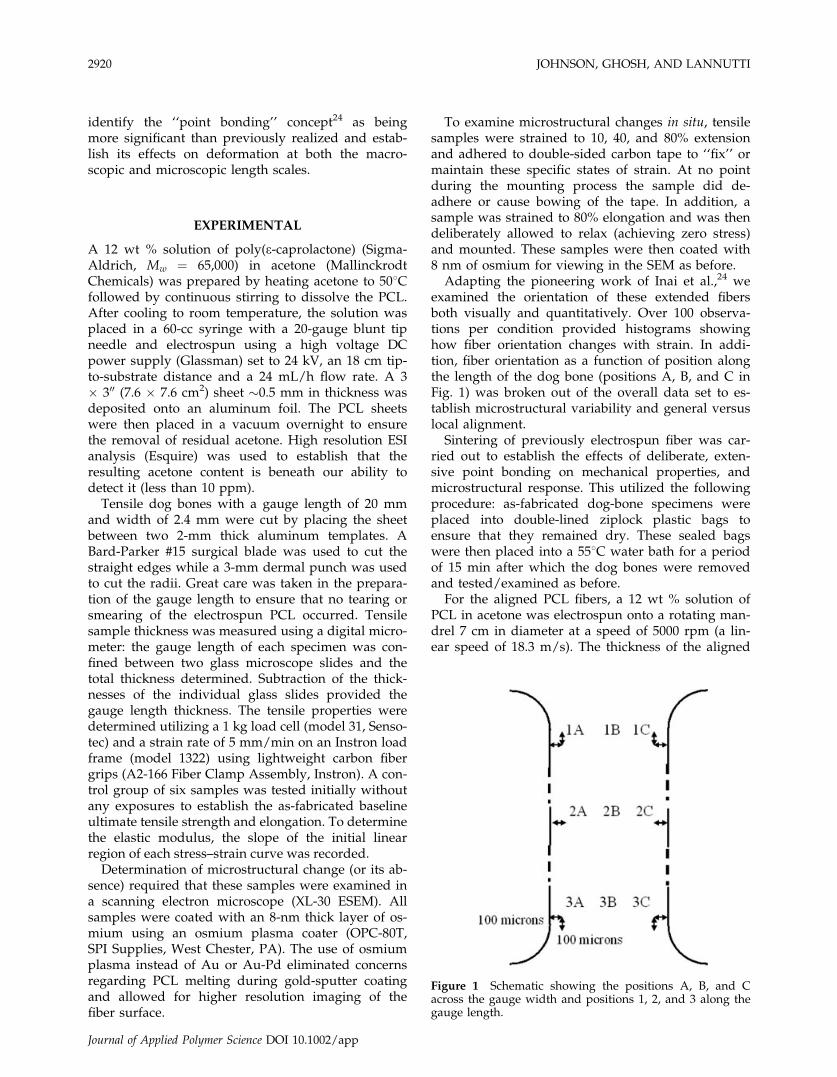
Adapting the pioneering work of Inai et al.,24 weexamined the orientation of these extended fibersboth visually and quantitatively. Over 100 observa-tions per condition provided histograms showinghow fiber orientation changes with strain. In addi-tion, fiber orientation as a function of position alongthe length of the dog bone (positions A, B, and C inFig. 1) was broken out of the overall data set to es-tablish microstructural variability and general versuslocal alignment.
Sintering of previously electrospun fiber was car-ried out to establish the effects of deliberate, exten-sive point bonding on mechanical properties, andmicrostructural response. This utilized the followingprocedure: as-fabricated dog-bone specimens wereplaced into double-lined ziplock plastic bags toensure that they remained dry. These sealed bagswere then placed into a 558C water bath for a periodof 15 min after which the dog bones were removedand tested/examined as before.
For the aligned PCL fibers, a 12 wt % solution ofPCL in acetone was electrospun onto a rotating man-drel 7 cm in diameter at a speed of 5000 rpm (a lin-ear speed of 18.3 m/s). The thickness of the aligned
Figure 1 Schematic showing the positions A, B, and Cacross the gauge width and positions 1, 2, and 3 along thegauge length.
2920 JOHNSON, GHOSH, AND LANNUTTI
Journal of Applied Polymer Science DOI 10.1002/app
PCL samples was � 70 mm. Tensile dog bones werethen cut in the longitudinal direction (the gaugelength being parallel to the fiber alignment) and inthe transverse direction (the gauge length being per-pendicular to the fiber alignment).
RESULTS
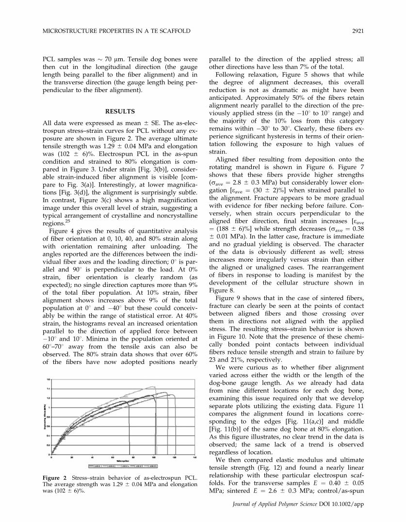
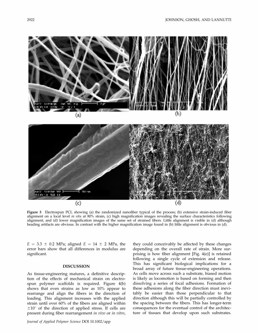
All data were expressed as mean 6 SE. The as-elec-trospun stress–strain curves for PCL without any ex-posure are shown in Figure 2. The average ultimatetensile strength was 1.29 6 0.04 MPa and elongationwas (102 6 6)%. Electrospun PCL in the as-spuncondition and strained to 80% elongation is com-pared in Figure 3. Under strain [Fig. 3(b)], consider-able strain-induced fiber alignment is visible [com-pare to Fig. 3(a)]. Interestingly, at lower magnifica-tions [Fig. 3(d)], the alignment is surprisingly subtle.In contrast, Figure 3(c) shows a high magnificationimage under this overall level of strain, suggesting atypical arrangement of crystalline and noncrystallineregions.25
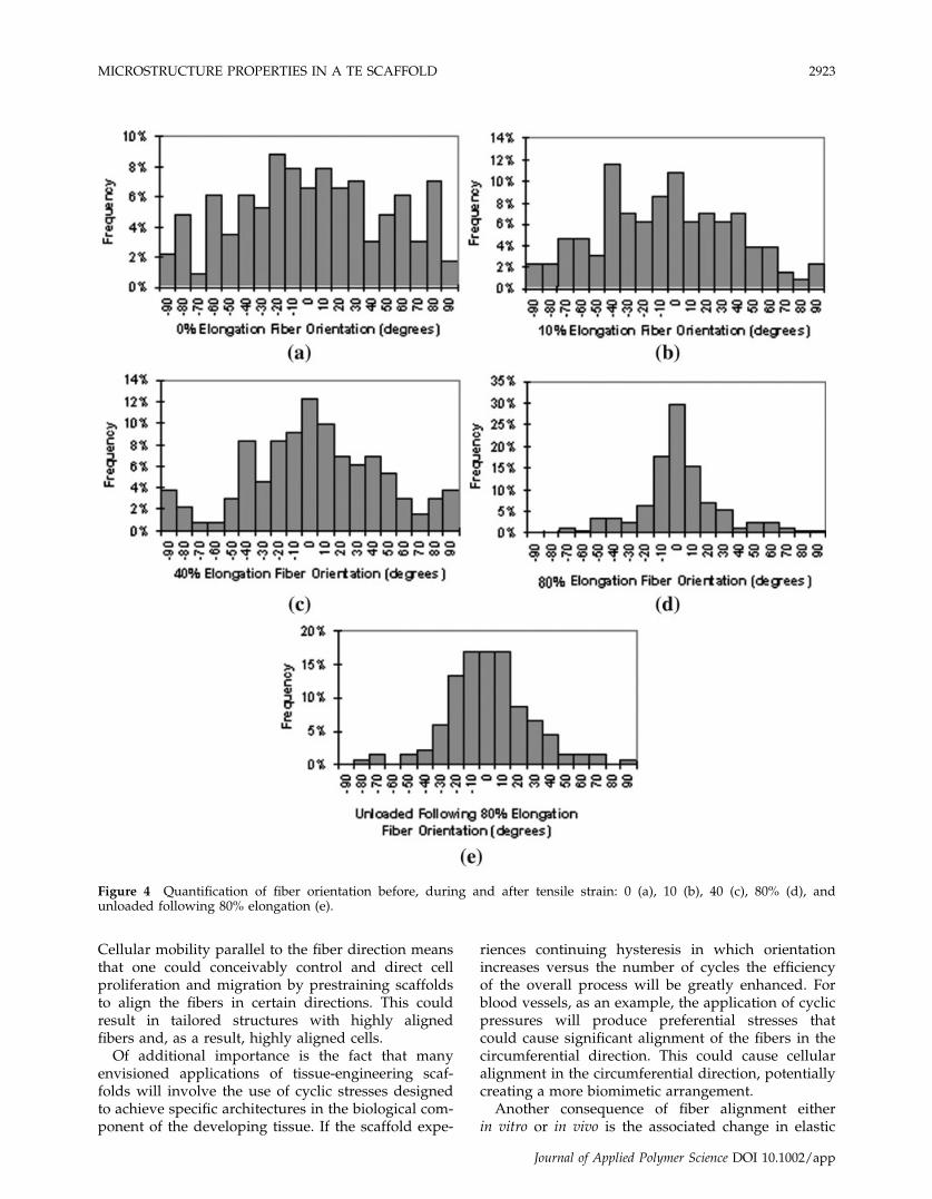
Figure 4 gives the results of quantitative analysisof fiber orientation at 0, 10, 40, and 80% strain alongwith orientation remaining after unloading. Theangles reported are the differences between the indi-vidual fiber axes and the loading direction; 08 is par-allel and 908 is perpendicular to the load. At 0%strain, fiber orientation is clearly random (asexpected); no single direction captures more than 9%of the total fiber population. At 10% strain, fiberalignment shows increases above 9% of the totalpopulation at 08 and �408 but these could conceiv-ably be within the range of statistical error. At 40%strain, the histograms reveal an increased orientationparallel to the direction of applied force between�108 and 108. Minima in the population oriented at608–708 away from the tensile axis can also beobserved. The 80% strain data shows that over 60%of the fibers have now adopted positions nearly
parallel to the direction of the applied stress; allother directions have less than 7% of the total.
Following relaxation, Figure 5 shows that whilethe degree of alignment decreases, this overallreduction is not as dramatic as might have beenanticipated. Approximately 50% of the fibers retainalignment nearly parallel to the direction of the pre-viously applied stress (in the �108 to 108 range) andthe majority of the 10% loss from this categoryremains within �308 to 308. Clearly, these fibers ex-perience significant hysteresis in terms of their orien-tation following the exposure to high values ofstrain.
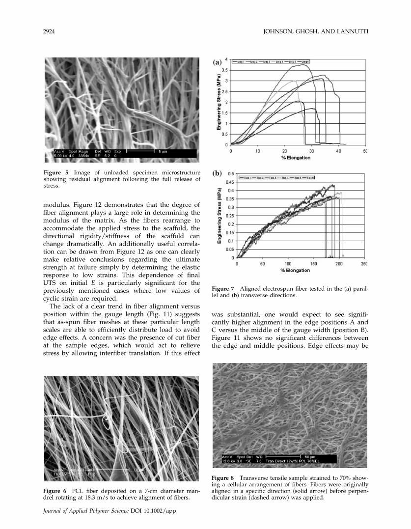
Aligned fiber resulting from deposition onto therotating mandrel is shown in Figure 6. Figure 7shows that these fibers provide higher strengths(save ¼ 2.8 6 0.3 MPa) but considerably lower elon-gation [eave ¼ (30 6 2)%] when strained parallel tothe alignment. Fracture appears to be more gradualwith evidence for fiber necking before failure. Con-versely, when strain occurs perpendicular to thealigned fiber direction, final strain increases [eave¼ (188 6 6)%] while strength decreases (save ¼ 0.386 0.01 MPa). In the latter case, fracture is immediateand no gradual yielding is observed. The characterof the data is obviously different as well; stressincreases more irregularly versus strain than eitherthe aligned or unaligned cases. The rearrangementof fibers in response to loading is manifest by thedevelopment of the cellular structure shown inFigure 8.
Figure 9 shows that in the case of sintered fibers,fracture can clearly be seen at the points of contactbetween aligned fibers and those crossing overthem in directions not aligned with the appliedstress. The resulting stress–strain behavior is shownin Figure 10. Note that the presence of these chemi-cally bonded point contacts between individualfibers reduce tensile strength and strain to failure by23 and 21%, respectively.
We were curious as to whether fiber alignmentvaried across either the width or the length of thedog-bone gauge length. As we already had datafrom nine different locations for each dog bone,examining this issue required only that we developseparate plots utilizing the existing data. Figure 11compares the alignment found in locations corre-sponding to the edges [Fig. 11(a,c)] and middle[Fig. 11(b)] of the same dog bone at 80% elongation.As this figure illustrates, no clear trend in the data isobserved; the same lack of a trend is observedregardless of location.
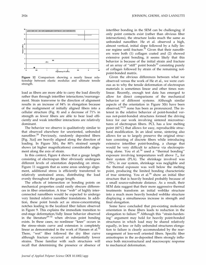
We then compared elastic modulus and ultimatetensile strength (Fig. 12) and found a nearly linearrelationship with these particular electrospun scaf-folds. For the transverse samples E ¼ 0.40 6 0.05MPa; sintered E ¼ 2.6 6 0.3 MPa; control/as-spun
Figure 2 Stress–strain behavior of as-electrospun PCL.The average strength was 1.29 6 0.04 MPa and elongationwas (102 6 6)%.
MICROSTRUCTURE PROPERTIES IN A TE SCAFFOLD 2921
Journal of Applied Polymer Science DOI 10.1002/app
E ¼ 3.3 6 0.2 MPa; aligned E ¼ 14 6 2 MPa, theerror bars show that all differences in modulus aresignificant.
DISCUSSION
As tissue-engineering matures, a definitive descrip-tion of the effects of mechanical strain on electro-spun polymer scaffolds is required. Figure 4(b)shows that even strains as low as 10% appear torearrange and align the fibers in the direction ofloading. This alignment increases with the appliedstrain until over 60% of the fibers are aligned within6108 of the direction of applied stress. If cells arepresent during fiber rearrangement in vivo or in vitro,
they could conceivably be affected by these changesdepending on the overall rate of strain. More sur-prising is how fiber alignment [Fig. 4(e)] is retainedfollowing a single cycle of extension and release.This has significant biological implications for abroad array of future tissue-engineering operations.As cells move across such a substrate, biased motionis likely as locomotion is based on forming and thendissolving a series of focal adhesions. Formation ofthese adhesions along the fiber direction must inevi-tably be easier than those perpendicular to thatdirection although this will be partially controlled bythe spacing between the fibers. This has longer-termconsequences for the eventual control of the architec-ture of tissues that develop upon such substrates.
Figure 3 Electrospun PCL showing (a) the randomized nanofiber typical of the process; (b) extensive strain-induced fiberalignment on a local level in situ at 80% strain, (c) high magnification images revealing the surface characteristics followingalignment, and (d) lower magnification images of the same set of strained fibers. Little alignment is visible in (d) althoughbeading artifacts are obvious. In contrast with the higher magnification image found in (b) little alignment is obvious in (d).
2922 JOHNSON, GHOSH, AND LANNUTTI
Journal of Applied Polymer Science DOI 10.1002/app
Cellular mobility parallel to the fiber direction meansthat one could conceivably control and direct cellproliferation and migration by prestraining scaffoldsto align the fibers in certain directions. This couldresult in tailored structures with highly alignedfibers and, as a result, highly aligned cells.
Of additional importance is the fact that manyenvisioned applications of tissue-engineering scaf-folds will involve the use of cyclic stresses designedto achieve specific architectures in the biological com-ponent of the developing tissue. If the scaffold expe-
riences continuing hysteresis in which orientationincreases versus the number of cycles the efficiencyof the overall process will be greatly enhanced. Forblood vessels, as an example, the application of cyclicpressures will produce preferential stresses thatcould cause significant alignment of the fibers in thecircumferential direction. This could cause cellularalignment in the circumferential direction, potentiallycreating a more biomimetic arrangement.
Another consequence of fiber alignment eitherin vitro or in vivo is the associated change in elastic
Figure 4 Quantification of fiber orientation before, during and after tensile strain: 0 (a), 10 (b), 40 (c), 80% (d), andunloaded following 80% elongation (e).
MICROSTRUCTURE PROPERTIES IN A TE SCAFFOLD 2923
Journal of Applied Polymer Science DOI 10.1002/app
modulus. Figure 12 demonstrates that the degree offiber alignment plays a large role in determining themodulus of the matrix. As the fibers rearrange toaccommodate the applied stress to the scaffold, thedirectional rigidity/stiffness of the scaffold canchange dramatically. An additionally useful correla-tion can be drawn from Figure 12 as one can clearlymake relative conclusions regarding the ultimatestrength at failure simply by determining the elasticresponse to low strains. This dependence of finalUTS on initial E is particularly significant for thepreviously mentioned cases where low values ofcyclic strain are required.
The lack of a clear trend in fiber alignment versusposition within the gauge length (Fig. 11) suggeststhat as-spun fiber meshes at these particular lengthscales are able to efficiently distribute load to avoidedge effects. A concern was the presence of cut fiberat the sample edges, which would act to relievestress by allowing interfiber translation. If this effect
was substantial, one would expect to see signifi-cantly higher alignment in the edge positions A andC versus the middle of the gauge width (position B).Figure 11 shows no significant differences betweenthe edge and middle positions. Edge effects may be
Figure 5 Image of unloaded specimen microstructureshowing residual alignment following the full release ofstress.
Figure 6 PCL fiber deposited on a 7-cm diameter man-drel rotating at 18.3 m/s to achieve alignment of fibers.
Figure 7 Aligned electrospun fiber tested in the (a) paral-lel and (b) transverse directions.
Figure 8 Transverse tensile sample strained to 70% show-ing a cellular arrangement of fibers. Fibers were originallyaligned in a specific direction (solid arrow) before perpen-dicular strain (dashed arrow) was applied.
2924 JOHNSON, GHOSH, AND LANNUTTI
Journal of Applied Polymer Science DOI 10.1002/app

present in considerably wider specimens as the inte-rior fibers become further isolated from the freeedges. For the moment, the accommodation of strainin this microstructure appears to be relatively globalat these particular levels of strain and overall strainrate.
We used a mandrel rotating at a linear speed of18.3 m/s to achieve the reasonably parallel fibersshown in Figure 6. Mathew et al.26 examined electro-spun PBT produced on a mandrel rotating at a simi-lar maximum speed. Although no microstructuralcharacterization of the as-strained material was pro-vided, they also observe a fourfold increase instrength in the direction of alignment and a similardecrease in strength perpendicular to that axis. Incontrast, Ayres et al.27 show an inconclusive trend ofstrength parallel versus perpendicular to the axis ofrotation for collagen fibers spun using a variety ofsolids concentrations.
By testing in both the longitudinal and transversedirections, we gained significant insight into the
mechanisms of strain and failure. In Figure 7(a), ori-entation along the axis of strain leads to transfer ofload to the fibers causing a gradual yielding processthat result from necking of individual fibers at manypoints in the microstructure followed by total failure.Conversely, the transverse direction samples yieldby extensive fiber rearrangement reflected in theragged nature of the stress–strain curve [Fig. 7(b)].The quantitative behaviors are reasonable in light ofthe alignment shown in Figure 4: pre-existing align-ment makes additional alignment more difficult(decreasing total strain) while increasing the allowed
Figure 9 SEM of PCL sintered at 558C for 15 min thenstrained (in the vertical direction) to 50%. Careful examina-tion reveals multiple points of fiber failure occurring atthe intersections between locally aligned and unalignedfibers.
Figure 10 Stress–strain behavior of point-bonded micro-structure following sintering at 558C for 15 min.
Figure 11 Quantification of fiber orientation versus posi-tion (a, b, and c, see Fig. 1) showing variable fiber align-ment across the gauge width at 80% elongation.
MICROSTRUCTURE PROPERTIES IN A TE SCAFFOLD 2925
Journal of Applied Polymer Science DOI 10.1002/app
load as fibers are more able to carry the load directlyrather than through interfiber interactions/rearrange-ment. Strain transverse to the direction of alignmentresults in an increase of 84% in elongation becauseof the realignment of initially aligned fibers into acellular structure (Fig. 8) and a decrease of 71% instrength as fewer fibers are able to bear load effi-ciently and weak interfiber interactions are relativelydominant.
The behavior we observe is qualitatively similar tothat observed elsewhere for unoriented, unbondednanofiber.28 Previously, randomly deposited fibers[Fig. 3(a)] are heavily aligned along the direction ofloading. In Figure 3(b), the 80% strained sampleshows (at higher magnifications) considerable align-ment along the axis of strain.
In this context, Figure 4 shows that a gauge lengthconsisting of electrospun fiber obviously undergoesdifferent levels of orientation depending on stress.Figure 11 suggests that as some areas undergo align-ment, additional stress is efficiently transferred torelatively unstrained areas, distributing the loadevenly throughout the gauge length.
The effects of intersection or bonding points onmechanical properties could easily obscure differen-ces in fiber orientation. A true ‘‘web’’ of highly inter-connected nanofibers would be expected to undergovery limited relative nanofiber translations. In addi-tion, these point bonds act as stress-concentratingnotches leading to the localized fiber failure observedin Figure 9. This explains the immediate transition toend-stage deformation/fully linear behavior observedin the literature29–32 when obvious point bondingexists. In these cases, no nonlinear ‘‘knee’’ occurs inthe stress–strain curve and extension is completelylinear as demonstrated in the work of Hansen et al.32
There, ‘‘wet’’ fiber followed the dry fiber curvealthough fracture occurred at substantially lowerstrains. Those familiar with such structures willrecall that determining the presence or absence of
interfiber bonding in the SEM can be challenging: ifonly point contacts exist (rather than obvious fiberintersections), the structure looks much the same asunbonded nanofiber. He et al. observed a high,almost vertical, initial slope followed by a fully lin-ear regime until fracture.31 Given that their nanofib-ers were both (1) collagen coated and (2) showedextensive point bonding, it seems likely that thisbehavior is because of the initial strain and fractureof an array of ‘‘stiff’’ point bonds33 consisting purelyof collagen followed by strain of the remaining not-point-bonded matrix.
Given the obvious differences between what weobserved versus the work of He et al., we were curi-ous as to why the tensile deformation of electrospunmaterials is sometimes linear and other times non-linear. Recently, enough test data has emerged toallow for direct comparisons of the mechanicalbehavior of different systems. Although similaraspects of the orientation in Figure 3(b) have beenobserved,24,29 none has been as pronounced. The in-terest in the relative behavior of point-bonded ver-sus not-point-bonded structures formed the drivingforce for our work involving sintered microstruc-tures of electrospun fibers. PCL has a low meltingpoint (608C) that allows for easy, reproducible struc-tural modification. In an ideal sense, sintering alsoallows for us to largely preserve the original struc-ture consisting of discrete fibers while introducingextensive interfiber point-bonding, a change thatwould be very difficult to achieve via electrospin-ning alone. You et al.34 used a ‘‘thermal bonding’’exposure involving temperatures well above Tm fortheir system (PLA). The shrinkage involved was�75%; in our system, shrinkage was negligible andthe thermal exposure was well below the meltingpoint, producing the limited bonding characteristicof true sintering. You et al.34 show an initial fiberstructure that is heavily bonded probably because ofa small source-substrate distance. As a result, theirSEM data suggest that their more aggressive thermaltreatments transform an initial weblike structureinto a much more heavily bonded weblike structuredisplaying a simultaneous increase in strength andfinal elongation.
Some have concluded that pre-existing molecularorientation in these fibers leads to reduction in theelongation to failure.29 Although this ‘‘strain-harden-ing’’ argument may hold for heavily point-bondedstructures in which load may be shared relativelyequally, in less- or fully unbonded structures elonga-tion to failure is clearly accommodated by the rear-rangement of less-well oriented fibers. Specific fiberanisotropies in the as-deposited fibers strongly influ-ence both microstructural and macroscopic responseto mechanical deformation.
Figure 12 Comparison showing a nearly linear rela-tionship between elastic modulus and ultimate tensilestrength.
2926 JOHNSON, GHOSH, AND LANNUTTI
Journal of Applied Polymer Science DOI 10.1002/app

Perhaps appropriate to the reduced values of scaleassociated with what are often referred to as poly-mer ‘‘nanofibers,’’ we see considerable overlap bet-ween the components of basic, classic explanationsof thermoplastic polymer chain behavior, and thebehavior of electrospun fiber:
1. Alignment of elements in the direction of strain.2. Unaligned elements held together by physical
(overlap, entanglement) and weak frictionalinteractions.
3. Translation between elements allowing perma-nent macroscopic deformation.
Like secondary bonding concepts, in polymerchains electrospun fibers, when strained, rearrangeand translate to align along the direction of loading.
This view of electrospun fiber deformation is obvi-ously informed by standard crazing phenomena inwhich fibrils containing well-oriented polymer chainsform. Unoriented polymer chains in the vicinity ei-ther collapse or are eventually oriented and addedto the fibrils. Electrospun polymer fibers appearto follow an identical hierarchy of rearrangementdriven by the applied macroscopic stress. Recently,Tan et al.35 used AFM to demonstrate that the tensilebehavior of individual electrospun PEO fibers wasessentially equal to that of the bulk. In all casesreported in the literature to date, assemblies of elec-trospun fiber are found to be far weaker than theirbulk counterparts. Issues related to fiber rearrange-ment and early failure are clearly the cause of thisdiscrepancy.
CONCLUSIONS
The strain and failure mechanisms of electrospunPCL involve the rearrangement and alignment ofsubstantial fractions of individual nanofibers. Thesesubstantial changes could have considerable effectson the form and viability of any adherent/interpene-trating cells and the resulting strength of the nano-fiber matrix. Dramatic microstructural change instrained nanofibers would likely rearrange, loosen oreven eliminate contacts between nanofibers, and ad-herent cells. This concept becomes critical in predict-ing and understanding the physical and biologicalperformance of cell–tissue constructs as theyundergo strain either in vivo or in vitro.
Any opinions, findings, and conclusions or recommenda-tions expressed in this material are those of the authorsand do not necessarily reflect the views of the NationalScience Foundation. We express our deepest thanks toDarrell Reneker of the University of Akron for his com-ments and support.
References
1. Pham, Q. P.; Sharma, U.; Mikos, A. G. Tissue Eng 2006, 12, 1197.2. Lannutti, J.; Reneker, D.; Ma, T.; Tomasko, D.; Farson, D.
Mater Sci Eng C, to appear.3. Li, W. J.; Tuli, R.; Huang, X. X.; Laquerriere, P.; Tuan, R. S.
Biomaterials 2005, 26, 5158.4. Fujihara, K.; Kotaki, M.; Ramakrishna, S. Biomaterials 2005, 26,
4139.5. Kwon, I. K.; Kidoaki, S.; Matsuda, T. Biomaterials 2005, 26, 3929.6. Zeng, J.; Chen, X. S.; Liang, Q. Z.; Xu, X. L.; Jing, X. B. Macro-
mol Biosci 2004, 4, 1118.7. Khil, M. S.; Bhattarai, S. R.; Kim, H. Y.; Kim, S. Z.; Lee, K. H.
J Biomed Mater Res Part B: Appl Biomater 2005, 72, 117.8. Zhang, Y. Z.; Ouyang, H. W.; Lim, C. T.; Ramakrishna, S.;
Huang, Z. M. J Biomed Mater Res Part B: Appl Biomater 2005,72, 156.
9. Li, W. J.; Tuli, R.; Okafor, C.; Derfoul, A.; Danielson, K. G.;Hall, D. J.; Tuan, R. S. Biomaterials 2005, 26, 599.
10. Hsu, C. M.; Shivkumar, S. J Mater Sci 2004, 39, 3003.11. Hsu, C. M.; Shivkumar, S. Macromol Mater Eng 2004, 289, 334.12. Shin, M.; Ishii, O.; Sueda, T.; Vacanti, J. P. Biomaterials 2004,
25, 3717.13. Shin, M.; Yoshimoto, H.; Vacanti, J. P. Tissue Eng 2004, 10, 33.14. Li, W. J.; Danielson, K. G.; Alexander, P. G.; Tuan, R. S.
J Biomed Mater Res A 2003, 67, 1105.15. Zeng, J.; Chen, X. S.; Xu, X. Y.; Liang, Q. Z.; Bian, X. C.; Yang,
L. X.; Jing, X. B. J Appl Polym Sci 2003, 89, 1085.16. Yoshimoto, H.; Shin, Y. M.; Terai, H.; Vacanti, J. P. Biomateri-
als 2003, 24, 2077.17. Lee, K. H.; Kim, H. Y.; Khil, M. S.; Ra, Y. M.; Lee, D. R. Poly-
mer 2003, 44, 1287.18. Agarwal, S.; Deschner, J.; Long, P.; Verma, A.; Hofman, C.;
Evans, C. H.; Piesc, N. Arthritis Rheum 2004, 50, 3541.19. Deschner, J.; Hofman, C. R.; Piesco, N. P.; Agarwal, S. Curr
Opin Clin Nutr Metab Care 2003, 6, 289.20. Long, P.; Gassner, R.; Agarwal, S. Arthritis Rheum 2001, 44, 2311.21. Deschner, J.; Perera, P.; Wang, Z.; Lannutti, J.; Agarwal, S.
Tissue Eng 2006, 12, 998.22. Annis, D.; Bornat, A.; Edwards, R. O.; Higham, A.; Loveday,
B.; Wilson, J. Trans Am Soc Artif Intern Organs 1978, 24, 209.23. Shin, H. J.; Lee, C. H.; Cho, I. H.; Kim, Y. J.; Lee, Y. J.; Kim,
I. A.; Park, K. D.; Yui, N.; Shin, J. W. J Biomater Sci Polym Ed2006, 17, 103.
24. Inai, R.; Kotaki, M.; Ramakrishna, S. J Polym Sci Part B: PolymPhys 2005, 43, 3205.
25. Cicero, J. A.; Dorgan, J. R. J Polym Environ 2001, 9, 1.26. Mathew, G.; Hong, J. P.; Rhee, J. M.; Leo, D. J.; Nah, C. J Appl
Polym Sci 2006, 101, 2017.27. Ayres, C.; Bowlin, G. L.; Henderson, S. C.; Taylor, L.; Shultz,
J.; Alexander, J.; Telemeco, T. A.; Simpson, D. G. Biomaterials2006, 27, 5524.
28. Zhao, Z. Z.; Li, J. Q.; Yuan, X. Y.; Li, X.; Zhang, Y. Y.; Sheng, J.J Appl Polym Sci 2005, 97, 466.
29. Pedicini, A.; Farris, R. J. Polymer 2003, 44, 6857.30. Lee, K. H.; Kim, H. Y.; Ryu, Y. J.; Kim, K. W.; Choi, S. W.
J Polym Sci Part B: Polym Phys 2003, 41, 1256.31. He, W.; Ma, Z. W.; Yong, T.; Teo, W. E.; Ramakrishna, S. Bio-
materials 2005, 26, 7606.32. Hansen, L. M.; Smith, D. J.; Reneker, D. H.; Kataphinan, W.
J Appl Polym Sci 2005, 95, 427.33. Huang, Z. M.; Zhang, Y. Z.; Ramakrishna, S. J Polym Sci Part
B: Polym Phys 2005, 43, 2852.34. You, Y.; Lee, S. W.; Lee, S. J.; Park, W. H. Mater Lett 2006, 60,
1331.35. Tan, E. P. S.; Goh, C. N.; Sow, C. H.; Lim, C. T. Appl Phys
Lett 2005, 86, 073115.
MICROSTRUCTURE PROPERTIES IN A TE SCAFFOLD 2927
Journal of Applied Polymer Science DOI 10.1002/app