INTRODUCTION 1 - Flexihire
252
1 - 1 INTRODUCTION 1 11
-
Upload
khangminh22 -
Category
Documents
-
view
2 -
download
0
Transcript of INTRODUCTION 1 - Flexihire

INTRODUCTION 1
11
1 - 1

1.1 ABOUT THIS MANUAL INTRODUCTION
1. INTRODUCTION 1
1.1 ABOUT THIS MANUAL 1
This manual describes procedures for proper operation, inspection, and maintenance of this lift truck, and rules youmust follow for your safety.Some actions involved in operation and maintenance of the lift truck can cause a serious accident if they are notdone in the manner described in this manual.
WARNINGThis manual describes fundamental prohibitions and precautions for operations, inspections, and maintenance of this lift truck.Failure to follow these instructions will result in a serious bodily injury or damage.Operators and service staffs must follow the followings before conducting operations, inspections, and maintenance of this lifttruck.Operators must understand this manual for conducting safety control of this lift truck.
• Read this manual carefully and understand it fully.
• Make sure you fully understand the instructions and safety indicators of this manual.
• For the lift truck equipped with options, read also "OPTIONS".
Be sure to store this manual in the designated location for the Operation and Maintenance Manual as shown below, so that it willbe avail for the concerned persons repeatedly as needed.If this manual has been lost or has become dirty or worn and cannot be read, request a replacement manual from your KOMATSUFORKLIFT distributor.When you transfer this lift truck to others, make sure to attach this manual together.
Continuing improvements in the design of this lift truck may not be reflected in this manual. Consult Komatsu Ltd. FORKLIFTCOMPANY or your KOMATSU FORKLIFT distributor for the latest available information on your lift truck or for questions regardinginformation in this manual.
TYPE AStorage location for Operation and Maintenance Manual• Retractable pocket behind the operator's seat (1)
TYPE BStorage location for Operation and Maintenance Manual• Operator’s seat back literature storage area (2)
1 - 2

INTRODUCTION 1.2 FOR YOUR SAFETY
1.2 FOR YOUR SAFETY 1
For your safety, the information of possible hazards and how to avoid them are provided on this manual and withthe safety indicators attached to this lift truck.
1.2.1 SIGNAL WORDS 1
The following signal words indicate the possible hazard which leads bodily injury.For this lift truck and this manual, the following signal words are used depending on the degree of possible hazard.
WARNING indicates a potentially hazardous situation which, if not avoided, could result indeath or serious injury.
CAUTION indicates a potentially hazardous situation which, if not avoided, may result inminor or moderate injury.
Other signal wordsBesides the above signal words, the followings indicate precautions you must take for the lift truck as well as usefulinformation.
NOTICE - - - - - - -The lift truck can get damaged or shortens its service life when handled incorrectly.
REMARKS - - - - -Useful information.
Example of safety message using signal word
CAUTIONDo not open the radiator cap immediately after the engine stops, sincethe coolant temperature is very high. Steam or boiling water may spurtout, causing burns. After the coolant temperature has gone down, turnthe cap slowly to release the pressure before removing it.
1 - 3

1.2 FOR YOUR SAFETY INTRODUCTION
1.2.2 SAFETY INDICATORS 1
Safety indicators are used in the various locations of the lift truck to indicate the possible hazards to the concernedpersons during operations, inspections, and maintenances.This lift truck employs [pictorial safety indicator] forsafety indicators.
EXAMPLE OF PICTORIAL SAFETY INDICATORThe pictorial safety indicators indicate the hazard equivalent to the signal words. Illustrations are used for thesesafety indicators to tell the operators and service staffs clearly of the existence and content of a hazard.In addition, there are pictorial indicators which simply indicate the prohibition content as well as indicators whichcomply with the international standards.
Komatsu Ltd. FORKLIFT COMPANY cannot predict every circumstance that the customers will experience.Therefore the precautions in this manual and on the lift truck may not include all possible safety precautions.When carrying out any procedures or actions which are not specifically recommended or allowed in this manual,it is your responsibility to carry out such procedures and actions safely.The explanations, numeric vales, and illustrations of this manual are based on the information at the time ofpublication. Continuing improvements in the design of this lift truck may not be reflected in this manual.Consult KOMATSU FORKLIFT distributor for the latest available information or for questions regarding thismanual.
1 - 4

INTRODUCTION 1.3 APPLICABLE MODEL AND SERIAL No.
1.3 APPLICABLE MODEL AND SERIAL No. 1
This Operation and Maintenance Manual applies to the following lift trucks.
1.4 GENERAL VIEW OF LIFT TRUCK 1
1.4.1 APPLICATION OF LIFT TRUCK 1
This lift truck is intended to use mainly for the following work.• Load handling with the forks of the lift truck.
1.4.2 DIRECTION OF LIFT TRUCK 1
This manual determines the left and right directions and fore and aft directions as seen from the operator's seat.
Model type Serial No.
FG10/15/18-21 M221-200001 and up
FG15H/18H-21 M256-200001 and up
FG20/25-17 M225-300001 and up
FG30/35A-17 M226-300001 and up
FG20H/25H-17 M227-300001 and up
FG20N/25N-17 M232-300001 and up
FG30N-17 M233-300001 and up
FD10/15/18-21 M223-200001 and up
FD20/25-17 M228-300001 and up
FD30-17 M229-300001 and up
FD20H/25H-17 M230-300001 and up
FD30H/35A-17 M231-300001 and up
Right
Left
Front Rear
1 - 5

1.5 UNITS OF MEASURE INTRODUCTION
1.5 UNITS OF MEASURE 1
This manual uses the international system of units (SI) for units of measure.Also the gravitational system of units, conventionally used, are provided as { } for reference.
1.6 QUALIFICATION FOR OPERATION 1
WARNINGOnly the trained and qualified persons are allowed to operate this lift truck. Operation by unqualified persons may result in seriousinjury or death.
1.7 RUNNING IN NEW LIFT TRUCK 1
1.7.1 RUNNING IN NEW LIFT TRUCK 1
Your KOMATSU FORKLIFT truck has been thoroughly adjusted and tested before shipment. However, operatemoderately during the first one month (or initial 200 hours) until each part of the lift truck comes into stable.Operating the lift truck under severe conditions at the beginning can adversely affect performance and shorten thelift truck life.
Be sure to run in the lift truck, taking special care concerning the followings.• Idle the engine for 5 minutes after starting it up.• Do not operate with heavy loads or at high speeds.• Avoid sudden starting, acceleration, braking, and sharp turning.
1.7.2 MAINTENANCE FOR NEW LIFT TRUCK 1
For new lift truck, carry out the followings after the first month or 200 hours: Replacement of oil and cleaning offilters, retightening of bolts and nuts. Have your lift truck serviced by KOMATSU FORKLIFT distributor.
1.8 WARRANTY AND SERVICE 1
1.8.1 PERIODICAL EXCHANGE PARTS 1
Other than those specified by the law, KOMATSU FORKLIFT designates "periodical exchange parts." Deteriorationof such parts is unavoidable over time but is critical for safety and therefore must be replaced periodically. Replacethose parts at the designated periods regardless of their appearance. For the periodic replacement of safety criticalparts, see the Section "4.15 PERIODIC REPLACEMENT OF SAFETY CRITICAL PARTS (PAGE 4-53)".
1.8.2 USE OF GENUINE KOMATSU PARTS AND OILS 1
Any problem caused by the use of other than Genuine Komatsu Parts (including oils) warranted by Komatsu is notcovered by the warranty.
1 - 6

INTRODUCTION 1.9 NECESSARY INFORMATION OF LIFT TRUCK
1.9 NECESSARY INFORMATION OF LIFT TRUCK 1
When you need maintenance of the lift truck or order parts, please provide KOMATSU FORKLIFT distributor withnecessary information of the lift truck such as model type, serial No. engine serial No. attachment, option, etc.
1.9.1 MEMORANDUM (To be filled by KOMATSU FORKLIFT distributor) 1
1.9.2 MODEL AND SERIAL NO. LOCATION 1
LIFT TRUCK SERIAL NO. PLATE LOCATIONLocated in the right top of the dashboard.
LIFT TRUCK EMBOSSED SERIAL NO. LOCATIONBesides the serial No. plate, serial No. is also embossed on the topof the left-side front wheel fender.
Example of embossed mark: M *** - #######Serial No. is shown as # after the hyphen.
Model type
Serial No.
Engine serial No.
Attachment/option
Distributor
Address
Telephone, fax No.
Service person in charge
Sales representative in charge
1 - 7

1.9 NECESSARY INFORMATION OF LIFT TRUCK INTRODUCTION
1.9.3 ENGINE SERIAL NO. PLATE OR EMBOSSED LOCATION 1
Engine serial No. is shown either by the plate or embossed in thelocation below.
• Gasoline engine (K15, K21, K25)
• Diesel engine (4D92E, 4D94LE, 4D98E)
1.9.4 HOUR METER LOCATION 1
Located in the center of the instrument panel under the steeringwheel.
1 - 8

INTRODUCTION CONTENTS
CONTENTS 11. INTRODUCTION --------------------------------------------------------------------------------------------------------------------- 1-1
1.1 ABOUT THIS MANUAL ----------------------------------------------------------------------------------------------------- 1-21.2 FOR YOUR SAFETY -------------------------------------------------------------------------------------------------------- 1-3
1.2.1 SIGNAL WORDS----------------------------------------------------------------------------------------------------- 1-31.2.2 SAFETY INDICATORS --------------------------------------------------------------------------------------------- 1-4
1.3 APPLICABLE MODEL AND SERIAL No. ------------------------------------------------------------------------------ 1-51.4 GENERAL VIEW OF LIFT TRUCK -------------------------------------------------------------------------------------- 1-5
1.4.1 APPLICATION OF LIFT TRUCK --------------------------------------------------------------------------------- 1-51.4.2 DIRECTION OF LIFT TRUCK ------------------------------------------------------------------------------------ 1-5
1.5 UNITS OF MEASURE------------------------------------------------------------------------------------------------------- 1-61.6 QUALIFICATION FOR OPERATION------------------------------------------------------------------------------------ 1-61.7 RUNNING IN NEW LIFT TRUCK----------------------------------------------------------------------------------------- 1-6
1.7.1 RUNNING IN NEW LIFT TRUCK -------------------------------------------------------------------------------- 1-61.7.2 MAINTENANCE FOR NEW LIFT TRUCK --------------------------------------------------------------------- 1-6
1.8 WARRANTY AND SERVICE ---------------------------------------------------------------------------------------------- 1-61.8.1 PERIODICAL EXCHANGE PARTS ----------------------------------------------------------------------------- 1-61.8.2 USE OF GENUINE KOMATSU PARTS AND OILS --------------------------------------------------------- 1-6
1.9 NECESSARY INFORMATION OF LIFT TRUCK --------------------------------------------------------------------- 1-71.9.1 MEMORANDUM (To be filled by KOMATSU FORKLIFT distributor) ----------------------------------- 1-71.9.2 MODEL AND SERIAL NO. LOCATION ------------------------------------------------------------------------ 1-71.9.3 ENGINE SERIAL NO. PLATE OR EMBOSSED LOCATION --------------------------------------------- 1-81.9.4 HOUR METER LOCATION---------------------------------------------------------------------------------------- 1-8
CONTENTS ------------------------------------------------------------------------------------------------------------------------- 1-92. SAFETY -------------------------------------------------------------------------------------------------------------------------------- 2-1
2.1 SAFETY LABEL--------------------------------------------------------------------------------------------------------------- 2-22.1.1 SAFETY LABEL LOCATION CHART--------------------------------------------------------------------------- 2-22.1.2 SAFETY LABELS ---------------------------------------------------------------------------------------------------- 2-4
2.2 FIRE PREVENTION --------------------------------------------------------------------------------------------------------- 2-82.2.1 ENGINE FIRE PREVENTION ------------------------------------------------------------------------------------ 2-8
2.2.1.1 CHECKING BEFORE STARTING THE ENGINE --------------------------------------------------- 2-82.2.2 PREVENTION FIRES CAUSED BY FUEL OR OIL --------------------------------------------------------2-122.2.3 PREVENTION OF FIRE CAUSED BY DEPOSITED OR ADHERED
FLAMMABLE SUBSTANCES ----------------------------------------------------------------------------------2-122.2.4 PREVENTION OF FIRE CAUSED BY FAULTY ELECTRICAL WIRING-----------------------------2-122.2.5 PREVENTION OF FIRE CAUSED BY FAULTY PIPING -------------------------------------------------2-122.2.6 CLEANING------------------------------------------------------------------------------------------------------------2-132.2.7 IF A FIRE BREAKS OUT------------------------------------------------------------------------------------------2-142.2.8 INSTALLATION OF FIRE EXTINGUISHER(IF EQUIPPED)--------------------------------------------2-15
2.3 BASIC PRECAUTIONS ----------------------------------------------------------------------------------------------------2-162.3.1 FOLLOW RULES ---------------------------------------------------------------------------------------------------2-162.3.2 NEVER OPERATE THE BROKEN-DOWN LIFT TRUCK ------------------------------------------------2-162.3.3 WEAR ADEQUATE CLOTHES AND SAFETY EQUIPMENT FOR OPERATION------------------2-172.3.4 FIRE EXTINGUISHER AND FIRST AID KIT-----------------------------------------------------------------2-172.3.5 CAUTIONS FOR SAFETY-RELATED EQUIPMENT ------------------------------------------------------2-172.3.6 PRACTICE SUFFICIENTLY BEFORE OPERATION ------------------------------------------------------2-172.3.7 JUMPING ON AND OFF FROM THE LIFT TRUCK IS STRICTLY PROHIBITED -----------------2-182.3.8 KEEP THE OPERATOR'S COMPARTMENT AND PLATFORM CLEAN AND TIDY -------------2-182.3.9 PRECAUTION WHEN WASHING LIFT TRUCK ------------------------------------------------------------2-182.3.10 TO AVOID BURN INJURY --------------------------------------------------------------------------------------2-192.3.11 FIRE PREVENTION ----------------------------------------------------------------------------------------------2-192.3.12 IF A FIRE BREAKS OUT ----------------------------------------------------------------------------------------2-202.3.13 DO NOT MODIFY THE LIFT TRUCK ------------------------------------------------------------------------2-202.3.14 DO NOT REMOVE THE OVERHEAD GUARD AND LOAD BACKREST --------------------------2-212.3.15 SECURE SAFETY AT THE WORKING AREA ------------------------------------------------------------2-212.3.16 ENGINE EXHAUST GAS IS POISONOUS -----------------------------------------------------------------2-212.3.17 ASBESTOS CAUTION-------------------------------------------------------------------------------------------2-222.3.18 WINDOW WASHER CAUTION--------------------------------------------------------------------------------2-22
1 - 9

CONTENTS INTRODUCTION
2.4 BEFORE STARTING OPERATION------------------------------------------------------------------------------------ 2-232.4.1 START-UP INSPECTION ---------------------------------------------------------------------------------------- 2-232.4.2 INSPECTION AND ADJUSTMENT BEFORE STARTING ENGINE ---------------------------------- 2-232.4.3 START-UP INSPECTION ---------------------------------------------------------------------------------------- 2-24
2.5 TRAVELING THE LIFT TRUCK----------------------------------------------------------------------------------------- 2-252.5.1 PREPARATION BEFORE TRAVELING THE LIFT TRUCK--------------------------------------------- 2-252.5.2 WHILE TRAVELING THE LIFT TRUCK---------------------------------------------------------------------- 2-262.5.3 STOPPING AND PARKING ------------------------------------------------------------------------------------- 2-322.5.4 TOWING -------------------------------------------------------------------------------------------------------------- 2-32
2.6 LOAD HANDLING OPERATION---------------------------------------------------------------------------------------- 2-332.7 PRECAUTIONS FOR INSPECTION AND MAINTENANCE----------------------------------------------------- 2-38
2.7.1 ALWAY PERFORM THE START-UP INSPECTION ------------------------------------------------------ 2-382.7.2 PUT UP A WARNING SIGN DURING INSPECTION AND MAINTENANCE ----------------------- 2-382.7.3 KEEP THE WORKING AREA CLEAN AND TIDY --------------------------------------------------------- 2-382.7.4 CAUTIONS BEFORE INSPECTION AND MAINTENANCE--------------------------------------------- 2-392.7.5 KEEP UNAUTHORIZED PEOPLE OFF---------------------------------------------------------------------- 2-392.7.6 USE OF RIGHT TOOLS AND EQUIPMENT ---------------------------------------------------------------- 2-392.7.7 CAUTIONS WHEN WORKING UNDER WORK EQUIPMENT----------------------------------------- 2-392.7.8 AVOID GETTING CAUGHT UP BY THE MAST OR FALLING OFF---------------------------------- 2-402.7.9 BE CAREFUL OF BOILING COOLANT ---------------------------------------------------------------------- 2-402.7.10 BE CAREFUL OF HIGH PRESSURE OIL ----------------------------------------------------------------- 2-412.7.11 BEWARE OF ROTATING COOLING FAN AND BELT ------------------------------------------------- 2-412.7.12 CAUTION WHEN REPAIRING THE ELECTRICAL SYSTEM ---------------------------------------- 2-412.7.13 CAUTIONS FOR USING COMPRESSED AIR FOR CLEANING ------------------------------------ 2-412.7.14 CAUTION WHEN HANDLING BATTERY ------------------------------------------------------------------ 2-422.7.15 STRICTLY FOLLOW THE INSTRUCTIONS SHOWN
BELOW TO AVOID GENERATION OF SPARKS ------------------------------------------------------- 2-422.7.16 CAUTION WHEN CHARGING A BATTERY--------------------------------------------------------------- 2-422.7.17 CAUTION WHEN HANDLING TYRES---------------------------------------------------------------------- 2-432.7.18 CAUTION IN WASTE DISPOSAL---------------------------------------------------------------------------- 2-442.7.19 CAUTION AFTER INSPECTION AND REPAIR ---------------------------------------------------------- 2-442.7.20 PERIODIC INSPECTION OF SAFETY CRITICAL PARTS -------------------------------------------- 2-44
2.8 HOISTING AND TRANSPORTING THE LIFT TRUCK ----------------------------------------------------------- 2-452.8.1 CAUTION WHEN HOISTING THE LIFT TRUCK ---------------------------------------------------------- 2-452.8.2 PRECAUTIONS FOR LOADING AND UNLOADING THE LIFT TRUCK ---------------------------- 2-45
2.9 STRUCTURE AND STABILITY OF THE LIFT TRUCK (TO PREVENT LIFT TRUCK FROM TIPPING) -------------------------------------------------------------------- 2-462.9.1 LONGITUDINAL STABILITY ------------------------------------------------------------------------------------ 2-462.9.2 CENTER OF GRAVITY OF A LOAD -------------------------------------------------------------------------- 2-462.9.3 COMBINED CENTER OF GRAVITY AND STABILITY
ON THE LOADED LIFT TRUCK ------------------------------------------------------------------------------ 2-472.9.4 ACTUAL CAPACITY----------------------------------------------------------------------------------------------- 2-472.9.5 SERIAL NO. AND LOAD TABLE ------------------------------------------------------------------------------- 2-482.9.6 INTRODUCTION OF OPTIONAL SAFETY DEVICE------------------------------------------------------ 2-50
2.10 TOWING--------------------------------------------------------------------------------------------------------------------- 2-513. OPERATION--------------------------------------------------------------------------------------------------------------------------- 3-1
3.1 GENERAL VIEW-------------------------------------------------------------------------------------------------------------- 3-23.1.1 GENERAL VIEW OF LIFT TRUCK ------------------------------------------------------------------------------ 3-23.1.2 INSTRUMENTS AND CONTROLS ------------------------------------------------------------------------------ 3-3
3.2 EXPLANATION OF COMPONENTS ------------------------------------------------------------------------------------ 3-53.2.1 METER PANEL ------------------------------------------------------------------------------------------------------- 3-53.2.2 OPERATING DEVICES--------------------------------------------------------------------------------------------- 3-93.2.3 REMOVING AND INSTALLATION OF ATTACHMENTS ------------------------------------------------ 3-14
3.3 OPERATION ----------------------------------------------------------------------------------------------------------------- 3-173.3.1 START-UP INSPECTION ---------------------------------------------------------------------------------------- 3-173.3.2 MOUNTING/DISMOUNTING AND OPERATING POSTURE ADJUSTMENT---------------------- 3-173.3.3 STARTING, GEAR SHIFTING, AND TRAVELING -------------------------------------------------------- 3-233.3.4 STARTING AND STOPPING ON SLOPE ------------------------------------------------------------------- 3-28
1 - 10

INTRODUCTION CONTENTS
3.3.5 INCHING TRAVEL--------------------------------------------------------------------------------------------------3-293.3.6 TURNING -------------------------------------------------------------------------------------------------------------3-293.3.7 OPERATION ON SNOWY AND FROZEN ROADS --------------------------------------------------------3-293.3.8 TEMPORARY STOPPING AND PARKING ------------------------------------------------------------------3-303.3.9 LOAD HANDLING OPERATION --------------------------------------------------------------------------------3-323.3.10 CHECKING AFTER OPERATION ----------------------------------------------------------------------------3-36
3.4 TRANSPORTATION--------------------------------------------------------------------------------------------------------3-374. INSPECTION AND MAINTENANCE-------------------------------------------------------------------------------------------- 4-1
4.1 ABOUT INSPECTION AND MAINTENANCE ------------------------------------------------------------------------- 4-24.2 START-UP INSPECTION -------------------------------------------------------------------------------------------------- 4-2
4.2.1 CHECKING ABNORMALITIES DETECTED ON THE PREVIOUS DAY ------------------------------ 4-44.2.2 WALK AROUND A LIFT TRUCK--------------------------------------------------------------------------------- 4-44.2.3 INSPECTION BY OPENING THE ENGINE HOOD --------------------------------------------------------- 4-64.2.4 CHECKING FROM THE OPERATOR SEAT ----------------------------------------------------------------4-114.2.5 CHECK BY SETTING THE STARTER SWITCH TO [ | ] (ON) POSITION ---------------------------4-134.2.6 CHECKING WITH THE ENGINE STARTED-----------------------------------------------------------------4-164.2.7 CHECKING WHILE TRAVELING SLOWLY------------------------------------------------------------------4-174.2.8 CHECKING BY OPERATING THE WORK EQUIPMENT LEVER -------------------------------------4-174.2.9 CHECKING OF SAFETY FUNCTION -------------------------------------------------------------------------4-19
4.3 CHECKING AND REPORTING AFTER OPERATION-------------------------------------------------------------4-204.4 SIMPLE MAINTENANCE--------------------------------------------------------------------------------------------------4-21
4.4.1 GREASES AND FUEL---------------------------------------------------------------------------------------------4-214.4.1.1 BASIC PRECAUTIONS -----------------------------------------------------------------------------------4-214.4.1.2 LUBRICANT LIST ------------------------------------------------------------------------------------------4-244.4.1.3 LUBRICANT LIST (GASOLINE ENGINE LIFT TRUCK) (FOR EU) ---------------------------4-254.4.1.4 LUBRICANT LIST (DIESEL ENGINE LIFT TRUCK) (FOR EU) --------------------------------4-26
4.4.2 AIR CLEANER ELEMENT CLEANING------------------------------------------------------------------------4-284.4.3 FUEL FILTER WATER DRAINING AND AIR BLEEDING (DIESEL ENGINE LIFT TRUCK)----4-294.4.4 REPLACING TYRES-----------------------------------------------------------------------------------------------4-304.4.5 ADJUSTING PARKING BRAKE LEVER OPERATING EFFORT---------------------------------------4-324.4.6 REPLACING FUSES-----------------------------------------------------------------------------------------------4-324.4.7 REPLACING BULBS -----------------------------------------------------------------------------------------------4-35
4.5 PROCEDURE FOR A DOWN BATTERY -----------------------------------------------------------------------------4-364.6 RUNNING IN COLD WEATHER-----------------------------------------------------------------------------------------4-384.7 ACTION IN ENGINE OVERHEATING ---------------------------------------------------------------------------------4-404.8 OPERATING LIFT TRUCKS IN SPECIAL ENVIRONMENT OR IN FORCIBLE WAY---------------------4-414.9 ACTION TO TAKE IF THE FORK FAILS TO LOWER -------------------------------------------------------------4-424.10 WASHING LIFT TRUCK -------------------------------------------------------------------------------------------------4-434.11 LONG-TERM STORAGE ------------------------------------------------------------------------------------------------4-444.12 HOISTING LIFT TRUCK -------------------------------------------------------------------------------------------------4-454.13 LOADING AND UNLOADING OF LIFT TRUCK -------------------------------------------------------------------4-464.14 INSPECTION AND MAINTENANCE SCHEDULE CHART -----------------------------------------------------4-474.15 PERIODIC REPLACEMENT OF SAFETY CRITICAL PARTS -------------------------------------------------4-534.16 SERVICE DATA------------------------------------------------------------------------------------------------------------4-54
5. TECHNICAL DATA ------------------------------------------------------------------------------------------------------------------ 5-16. EC DECLARATION OF CONFORMITY---------------------------------------------------------------------------------------- 6-1
6.1 EC DECLARATION OF CONFORMITY (FG(D)10 - 18-21) ------------------------------------------------------- 6-26.2 EC DECLARATION OF CONFORMITY (FG(D)20 - 35A-17) ----------------------------------------------------- 6-36.3 EC DECLARATION OF CONFORMITY (FD20 - 35A-17)---------------------------------------------------------- 6-46.4 TIE-DOWN POSITIONS OF LIFT TRUCK ---------------------------------------------------------------------------- 6-4
7. LPG FORK LIFT ---------------------------------------------------------------------------------------------------------------------- 7-17.1 CHAPTER CONTENTS----------------------------------------------------------------------------------------------------- 7-27.2 SAFETY LABELS------------------------------------------------------------------------------------------------------------- 7-2
7.2.1 SAFETY LABEL LOCATIONS ------------------------------------------------------------------------------------ 7-27.2.2 SAFETY LABELS ---------------------------------------------------------------------------------------------------- 7-2
7.3 BASIC PRECAUTIONS ----------------------------------------------------------------------------------------------------- 7-37.4 OPERATING THE LPG FORKLIFT-------------------------------------------------------------------------------------- 7-5
7.4.1 PART NAME----------------------------------------------------------------------------------------------------------- 7-5
1 - 11

CONTENTS INTRODUCTION
7.4.2 DESCRIPTION OF COMPONENTS ---------------------------------------------------------------------------- 7-67.5 REFUELING (LP GAS) ---------------------------------------------------------------------------------------------------- 7-10
7.5.1 REFUELING (LP GAS) BY REPLACING THE LPG CYLINDER--------------------------------------- 7-107.5.1.1 FORKLIFT W/ SWING BRACKET--------------------------------------------------------------------- 7-107.5.1.2 FORKLIFT W/ SWING-DOWN BRACKET ---------------------------------------------------------- 7-147.5.1.3 FORKLIFT W/ DOUBLE CYLINDER BRACKET--------------------------------------------------- 7-18
7.5.2 REFUELING (LP GAS) THE LPG CYLINDER WHEN MOUNTED ON THE FORKLIFT -------- 7-217.6 PRESTART INSPECTION------------------------------------------------------------------------------------------------ 7-22
7.6.1 INSPECTING THE LPG CYLINDER WHILE MOUNTED ON THE FORKLIFT -------------------- 7-227.6.2 CHECKING THE CHARGE AND DISCHARGE VALVES------------------------------------------------ 7-227.6.3 CHECKING THE LPG LEVEL----------------------------------------------------------------------------------- 7-237.6.4 CHECKING THE HOT WATER HOSE CONNECTION -------------------------------------------------- 7-237.6.5 CHECKING THE ELECTRICAL WIRING -------------------------------------------------------------------- 7-237.6.6 CHECKING THE HIGH-PRESSURE LINES FOR GAS LEAKS --------------------------------------- 7-247.6.7 CHECKING THE COOLANT LEVEL -------------------------------------------------------------------------- 7-25
7.7 OPERATING ----------------------------------------------------------------------------------------------------------------- 7-267.7.1 STARTING ENGINE W/ LP GAS------------------------------------------------------------------------------- 7-267.7.2 STARTING THE ENGINE IN COLD CONDITIONS ------------------------------------------------------- 7-297.7.3 SWITCHING FUEL FROM LP GAS TO GASOLINE ------------------------------------------------------ 7-317.7.4 SWITCHING FUEL FROM GASOLINE TO LP GAS ------------------------------------------------------ 7-337.7.5 STOPPING LP GAS DRIVEN ENGINES--------------------------------------------------------------------- 7-357.7.6 STOPPING GASOLINE DRIVEN ENGINES ---------------------------------------------------------------- 7-36
7.8 BASIC MAINTENANCE --------------------------------------------------------------------------------------------------- 7-377.8.1 CHECK AND DRAINING OF TAR IN THE VAPORIZER ------------------------------------------------ 7-377.8.2 CLEANING THE LPG FILTER ---------------------------------------------------------------------------------- 7-38
7.9 PARKING, DISUSE, STORAGE ---------------------------------------------------------------------------------------- 7-387.10 INSPECTION AND MAINTENANCE SCHEDULE---------------------------------------------------------------- 7-397.11 PERIODIC REPLACEMENT OF SAFETY CRITICAL PARTS ------------------------------------------------ 7-407.12 SERVICE DATA ----------------------------------------------------------------------------------------------------------- 7-41
8. ATTACHMENT------------------------------------------------------------------------------------------------------------------------ 8-18.1 OPERATION OF SIDE SHIFT--------------------------------------------------------------------------------------------- 8-2
8.1.1 ATTACHMENT MODEL PLATE LOCATION, SERIAL NO. ----------------------------------------------- 8-28.1.2 SAFETY OF ATTACHEMENTS ---------------------------------------------------------------------------------- 8-38.1.3 SAFETY LABEL ------------------------------------------------------------------------------------------------------ 8-48.1.4 FEATURES OF ATTACHMENTS-------------------------------------------------------------------------------- 8-68.1.5 GENERAL VIEW ----------------------------------------------------------------------------------------------------- 8-78.1.6 EXPLANATION OF COMPONENTS---------------------------------------------------------------------------- 8-88.1.7 OPERATION--------------------------------------------------------------------------------------------------------- 8-108.1.8 INSPECTION AND MAINTENANCE SCHEDULE CHART---------------------------------------------- 8-128.1.9 MAINTENANCE WORK ------------------------------------------------------------------------------------------ 8-13
9. OPTIONS------------------------------------------------------------------------------------------------------------------------------- 9-19.1 HANDLING OF LOAD CHECKER WITH OVERLOAD ALARM -------------------------------------------------- 9-29.2 HANDLING OF MAST TILT ANGLE METER + AUTO STOP FUNCTION------------------------------------- 9-39.3 HANDLING OF LASER LIFT HEIGHT SENSOR--------------------------------------------------------------------- 9-4
9.3.1 MAIN SPECIFICATIONS AND EXPLANATION-------------------------------------------------------------- 9-49.3.2 EXPLANATION OF OPERATION-------------------------------------------------------------------------------- 9-59.3.3 PRECAUTIONS FOR HANDLING ------------------------------------------------------------------------------- 9-6
9.4 TRAVEL SPEED LIMITER ------------------------------------------------------------------------------------------------- 9-810. INDEX-------------------------------------------------------------------------------------------------------------------------------- 10-1
1 - 12

2 - 1
SAFETY 2
22
WARNINGPlease be sure that you fully understand this manual and the precautionsrelated to safety for the lift truck.When operating, inspecting, or servicing the lift truck, always follow theseprecautions strictly.

2.1 SAFETY LABEL SAFETY
2 - 2
2. SAFETY 2
2.1 SAFETY LABEL 2
Followings are the safety labels used for this lift truck.• Make sure that you understand the exact locations of the safety labels, the contents of the danger, and how to
avoid them.• Keep the safety labels clean so that it can be easily seen at all times. Do not use organic solvent or gasoline for
cleaning. Or the safety label may come unstuck.• If the safety label is damaged, lost, or become unreadable, replace it with a new one. Before placing an order
to KOMATSU FORKLIFT distributor, check the part No. of safety label referring to this manual or the replacinglabel itself.
• Concerning labels other than the safety labels, use these in the same way.
2.1.1 SAFETY LABEL LOCATION CHART 2
Engine room (Diesel engine lift truck) Engine room (Gasoline engine lift truck)
Engine room (OPS only)

SAFETY 2.1 SAFETY LABEL
2 - 3
No. Safety labels name Position
1 Caution to avoid getting hand caught Rear side of tilt mast stay and head stay
2Prohibit the operators from riding on the forks and lifting/lowering themselves
Outside of left and right outer masts
3 Jump start prohibited Starting motor (Inside of engine hood)
4Avoiding danger if lift truck tips over during operations
Right inside of overhead guard
5 Take a right posture while operating lift truck Right inside of overhead guard
6 Caution when hoisting the lift truck Inside of overhead guard left leg
7 Caution for explosion of gas spring (*1) Gas spring
8 Precaution when washing lift truck (*2) Inside of engine hood
9 Caution to avoid getting caught Inside of engine hood
10 Caution when handling radiator (*1) Radiator (Inside of counterbalance-weight cover)
KOMATSU FORKLIFT reserves the right to change or add to these safety label requirements and label contents.*1 : For EU specification only*2 : Lift truck equipped with OPS (Operator presence sensing system).

2.1 SAFETY LABEL SAFETY
2 - 4
2.1.2 SAFETY LABELS 2
(1) Caution to avoid getting hand caught. (3EB-96-25121)• Do not place your hands.
(2) Prohibit the operators from riding on the forks and lifting/lowering themselves (3EB-96-25131)• Never enter the area under the forks.
(3) Jump start prohibited (09842-A0481)• Start the engine only after sitting down in the operator's seat.• Do not attempt to start the engine by intentionally short-
circuiting the engine starting circuit. Such a malpractice cancause a serious bodily injury and fire.

SAFETY 2.1 SAFETY LABEL
2 - 5
(4) Avoiding danger if lift truck tips over during operations (3EB-96-32610)
(5) Take a right posture while operating lift truck (3EB-96-59231)(TORQFLOW transmission lift truck with OPS only)• If you operate the lift truck in such a posture that your weight is not properly applied to the seat, like standing
up or leaning forward/backward or sideways, the power will be cut off in approx. three seconds, makingtravel and lift truck operation impossible. Take a right posture while operating.It is especially dangerous when you operate like this on an uphill. Due to the power is cut off, the lift truckwill slither down even if you depress the accelerator pedal, which can lead an accident such as crash orfalling off.
(6) Caution when hoisting the lift truck (3EB-96-64121)• Never lift the truck by the overhead guard.
BEFORE OPERATION:IF THE LIFT TRUCK SEEMS TO TIP OVER ANY MOMENT DURING OPERATION:
1. Always use your seat belt when operating. 3. Do not jump off the lift truck.
2. Read and understand the Operation and Maintenance Manual.
4. Lean yourself in the opposite direction to the tipping of the lift truck.
5. Grip the steering wheel tightly.
6. Brace yourself with both feet to support your body.

2.1 SAFETY LABEL SAFETY
2 - 6
(For EU)(7) Caution for explosion of gas spring (09659-A057B) (*)• There is the hazard of explosion causing injury.• Do not disassemble the gas spring, make holes in it, weld it,
cut it, hit it, bring it near flame.* : For EU specification only
(8) Precaution when washing lift truck (37B-1QC-5030)• For washing the lift trucks, see the Section "4.10 WASHING
LIFT TRUCK (PAGE 4-43)".
(9) Caution to avoid getting caught (37B-1QL-5030)• Keep hand off the rotating fan.
(For EU)(10) Caution when handling radiator (09653-A0361) (*)• For handling of the radiator, see the Section "2.7.9 BE
CAREFUL OF BOILING COOLANT (PAGE 2-40)".* : For EU specification only

SAFETY 2.1 SAFETY LABEL
2 - 7
(11) Caution when handling battery(Shape and layout may vary depending on the batterysupplier.)• For handling of the battery, see the Section "2.7.14
CAUTION WHEN HANDLING BATTERY (PAGE 2-42)" and"2.7.15 STRICTLY FOLLOW THE INSTRUCTIONSSHOWN BELOW TO AVOID GENERATION OF SPARKS(PAGE 2-42)" and "2.7.16 CAUTION WHEN CHARGING ABATTERY (PAGE 2-42)".
(For EU)
(12) Caution before operation (09651-A0481)(Caut ion label may be at tached depending on thespecifications.)• Warning: Be sure to read the Operation and Maintenance Manual
thoroughly before operating, servicing, disassembling,
assembling or transporting.

2.2 FIRE PREVENTION SAFETY
2 - 8
2.2 FIRE PREVENTION 2
2.2.1 ENGINE FIRE PREVENTION 2
2.2.1.1 CHECKING BEFORE STARTING THE ENGINE 2
Always check the following points before starting the lift truckengine. If you find a loosely connected battery terminal, secure it.Also, if you find any abnormalities such as accumulation of dirt, treewaste or paper, clean them off.If the problem persists, do not hesitate to contact your KOMATSUFORKLIFT distributor for servicing.1. Checking around the engine
• Accumulation of tree waste or paper around the hot enginearea and its circumference
• Oil leakage or fuel leakage around the engine• Damage or gas leakage of muffler or exhaust pipe
REMARKThese instructions apply to the following diesel engine lift trucks(see illustrations at right).A : FD20/FD20H/FD25/FD25H/FD30/FD30H/FD35A-17B : FD10/FD15/18-21
[Diesel engine lift truck]
A
[Diesel engine lift truck]
B
[Gasoline engine lift truck]

SAFETY 2.2 FIRE PREVENTION
2 - 9
• Loosen or damaged electrical wiring or clamps around theengine
REMARKThese instructions apply to the following diesel engine lift trucks(see illustrations at right).A : FD20/FD20H/FD25/FD25H/FD30/FD30H/FD35A-17B : FD10/FD15/18-21
[Diesel engine lift truck]
A
[Diesel engine lift truck]
B
[Gasoline engine lift truck]

2.2 FIRE PREVENTION SAFETY
2 - 10
2. Checking around batteries• Loose or corroded battery terminals, connectors or clamps• Accumulation of tree waste, paper or entry of metals around
batteries• Damage of cable or wiring harness
REMARKThese instructions apply to the following diesel engine lift trucks(see illustrations at right).A : FD20/FD20H/FD25/FD25H/FD30/FD30H/FD35A-17B : FD10/FD15/18-21
3. Checking oil or fuel leakage• Oil leakage from hydraulic piping or fuel leakage from fuel
tank (1)
[Diesel engine lift truck]
A
[Diesel engine lift truck]
B
[Gasoline engine lift truck]

SAFETY 2.2 FIRE PREVENTION
2 - 11
• Accumulation of tree waste or paper around fuel tank (1) orhydraulic oil tank (2)
• Accumulation of dirt under the frame (engine ortransmission system)In particular, dirt or paper may accumulate easily on a lifttruck with an undercover. Carefully check for suchaccumulation.
4. Checking the inside of the operator’s cab (for cab models)• Accumulation of cigarettes and other flammables

2.2 FIRE PREVENTION SAFETY
2 - 12
2.2.2 PREVENTION FIRES CAUSED BY FUEL OR OIL 2
Fuel, oil, coolant and window washer fluid are flammable, so keep them away from open flame.Strictly follow the instructions shown below.• Do not smoke or allow any flame near fuel, oil, coolant or window washer fluid, or clothes soaked in them.• Stop the engine before refilling fuel.• Do not leave the area while refilling fuel or oil.• Tighten the fuel cap and oil cap securely.• Do not spill fuel on the overheated surface or electrical system components.• Store fuel and oil in a well-ventilated dark cold place.• Store fuel and oil in a designated place away from unauthorized people.• Wipe off the spilled fuel, oil, and grease after refilling.• Put clothes soaked in oil and other flammable objects in a secure container and store them in a safe place.• Also, be cautious and take measures for fires ignited with a spark or flame, when inspecting or servicing the lift
truck using devices and equipment.Failure to comply with these safety policies may result in serious injury or death.
2.2.3 PREVENTION OF FIRE CAUSED BY DEPOSITED OR ADHERED FLAMMABLE SUBSTANCES 2
• Deposits or fouling of flammable objects in the engine exhaust manifold, muffler, exhaust pipe, near the battery,and inside the under cover may cause a fire. Remove the deposits and fouling from the above locations.
2.2.4 PREVENTION OF FIRE CAUSED BY FAULTY ELECTRICAL WIRING 2
Short-circuiting of the electrical wiring may cause a fire.• Clean all the electrical wiring connections, and fix them firmly.• Check daily for looseness, wear and damage of the wiring. Retighten the loose connector and wiring clamp.
Damaged wiring must be repaired or replaced by KOMATSU FORKLIFT distributor.
2.2.5 PREVENTION OF FIRE CAUSED BY FAULTY PIPING 2
• Make sure that the clamp, guard and cushion of the hose and tube are fixed securely. Loose hose or tube mayget damaged by vibration during operation or by rubbing against other parts, and cause the high pressure fluidto spurt out which may lead a fire or bodily injury.

SAFETY 2.2 FIRE PREVENTION
2 - 13
2.2.6 CLEANING 2
After operating, use an air blower or similar device to clean off anydirt, tree waste, and paper that has accumulated on the lift truck.• Around the engine
Carefully clean the circumference of the exhaust manifold.
REMARKThese instructions apply to the following diesel engine lift trucks(see illustrations at right).A : FD20/FD20H/FD25/FD25H/FD30/FD30H/FD35A-17B : FD10/FD15/18-21
• Under the frameIn particular, dirt or paper may accumulate easily on a lift truckwith an undercover. Carefully clean such accumulation.
A
[Diesel engine lift truck]
[Diesel engine lift truck]
B
[Gasoline engine lift truck]

2.2 FIRE PREVENTION SAFETY
2 - 14
• On the floor plate
REMARKThese instructions apply to the following diesel engine lift trucks(see illustrations at right).A : FD20/FD20H/FD25/FD25H/FD30/FD30H/FD35A-17B : FD10/FD15/18-21
• Around the muffler
2.2.7 IF A FIRE BREAKS OUT 2
• If a fire breaks out, turn the starting switch to the [Q] (OFF)position to stop the engine.
• Do not jump off the lift truck in a rush. Support yourself securelywith handrails and steps to evacuate.
[Diesel engine lift truck]
A
[Diesel engine lift truck]
B
[Gasoline engine lift truck]

SAFETY 2.2 FIRE PREVENTION
2 - 15
2.2.8 INSTALLATION OF FIRE EXTINGUISHER(IF EQUIPPED) 2
• If equipped, a fire extinguisher is provided. (1 kg)See the instruction plate attached on the fire extinguisher abouthow to use it.

2.3 BASIC PRECAUTIONS SAFETY
2 - 16
2.3 BASIC PRECAUTIONS 2
2.3.1 FOLLOW RULES 2
• Only the trained and qualified persons are allowed to operatethis lift truck.
• Fully understand and follow this operation and maintenancemanual.
• Do not operate the lift truck when you are ill conditioned, takingmedicine that causes drowsiness, under the influence ofalcohol, or mentally unstable.
• Plan safety work beforehand.Before operation, make up an operating plan that fits theworkplace conditions, type and capacity of the lift truck, and theload conditions.In confined areas or when loading/unloading large items,position a signal person and carry out operations in accordancewith their instructions.
• During operation, safety must be your primary responsibilityensuring the safety of those you are working around, the lifttruck, yourself, and other property in the work area.
2.3.2 NEVER OPERATE THE BROKEN-DOWN LIFT TRUCK 2
• If any abnormality is detected during the start-up inspection orduring the operation (noise, vibration, odor, maladjusted gauge,smoke, oil leak, or erroneous indication of warning device ormonitor), report the administrator immediately and takeadequate corrective actions.
• Do not operate the lift truck until the abnormality is corrected.• Remove the key from the faulty lift truck and put up signs in the
operator's compartment to prevent its use.• If the lift truck has a failure and must be parked without lowering
the forks, put markers on the tips of the forks and take steps toprevent pedestrians or other vehicles from hitting the forks.
• Select a parking place where people or vehicles do not pass.Take measures to prevent anyone to go under the forks. (Spaceunder lifted forks is dangerous zone.)
Danger
Never
use

SAFETY 2.3 BASIC PRECAUTIONS
2 - 17
2.3.3 WEAR ADEQUATE CLOTHES AND SAFETY EQUIPMENT FOR OPERATION 2
• Avoid loose clothing and accessories. It is dangerous when theycatch on control levers and projections.
• Long, loose hair can be caught in a rotating part. Long hair mustbe tied back.
• Always wear a safety helmet and safety shoes. Wear othersafety equipment appropriate for the working conditions or asmay be required by your administrator.
• Check that the safety equipment works properly before use.
2.3.4 FIRE EXTINGUISHER AND FIRST AID KIT 2
• In preparation for a fire or bodily injury, check the locations of fireextinguisher and first aid kit, and be familiar with the usage.
2.3.5 CAUTIONS FOR SAFETY-RELATED EQUIPMENT 2
• Confirm that all protective guards, covers, and mirrors areproperly mounted. Repair them immediately when broken.
• Be sure that you fully understand the usage of safety-relatedequipment.
• Never remove the safety-related equipment. Keep them fullyfunctional at any time.
• Do not operate this lift truck if the overhead guard or loadbackrest has been or appears to have been damaged orloosened until repairs have been made by your authorizedKOMATSU FORKLIFT distributor.
2.3.6 PRACTICE SUFFICIENTLY BEFORE OPERATION 2
• Take sufficient time for practice until you become familiar withthe operation of each component before starting the actualoperation.
• Even after you become familiar with it, operate with caution andavoid harsh operation.Or it can cause a bodily injury or damage.
• Each lift truck is more or less peculiar in the performance ofbrake, accelerator, and load handling device even though it isthe same model type. When you changeover the lift trucks,understand the peculiarity of each lift truck before statingoperation. Be especially careful with brake, s ince i tsperformance varies by individual lift truck.

2.3 BASIC PRECAUTIONS SAFETY
2 - 18
2.3.7 JUMPING ON AND OFF FROM THE LIFT TRUCK IS STRICTLY PROHIBITED 2
• Never jump on or off the lift truck. It is extremely dangerous.• Even if the lift truck accidentally starts to move without operator
onboard, never attempt to jump on the lift truck to stop.• Always mount and dismount the lift truck from the left side.• While mounting and dismounting the lift truck, always support
yourself securely with your hands and feet at more than 3locations; put your left foot on the step, grab the assist grip(handrail) with your left hand, and grab the backrest or hipsupport of the seat with your right hand.
• Do not hold on the control levers or steering wheel whenmounting or dismounting the lift truck.
2.3.8 KEEP THE OPERATOR'S COMPARTMENT AND PLATFORM CLEAN AND TIDY 2
• Always keep the operator's compartment and platform (assistgrip, step, floor) clean and tidy. Oil, mud or dust attached, orspare parts or tools left lying around in the operator'scompartment may cause the operator's hand or foot slips or theclothes get caught, which will lead a falling accident orerroneous operation.
2.3.9 PRECAUTION WHEN WASHING LIFT TRUCK 2
• If water gets into the electrical system (controller, sensor,connector, etc.), there is a hazard that it will cause malfunctionsor miss-movement. Do not use flushing water or high- pressuresteam to wash the electrical system. For washing the lift trucks,see the Section "4.10 WASHING LIFT TRUCK (PAGE 4-43)".

SAFETY 2.3 BASIC PRECAUTIONS
2 - 19
2.3.10 TO AVOID BURN INJURY 2
HIGH TEMPERATURE COOLANT• Immediately after the operation, the cooling water is at a high
temperature, so there is always the danger of burns if you openthe radiator cap as steam or boiling water may spurt out. Turnthe radiator cap slowly, after the coolant temperature has gonedown sufficiently.
HIGH TEMPERATURE PARTS AND OIL• To prevent burns with the high temperature parts or by the spurt
of oil, wait for the lift truck temperature to go down enoughbefore the inspection and maintenance work.
2.3.11 FIRE PREVENTION 2
FIRE WITH FUEL AND OILFuel, oil, coolant and window washer fluid are flammable, so keepthem away from open flame.Strictly follow the instructions shown below.• Do not smoke or allow any flame near fuel, oil, coolant or window
washer fluid, or clothes soaked in them.• Stop the engine before refilling fuel.• Do not leave the area while refilling fuel or oil.• Tighten the fuel cap and oil cap securely.• Do not spill fuel on the overheated surface or electrical system
components.• Store fuel and oil in a well-ventilated dark cold place.• Store fuel and oil in a designated place away from unauthorized
people.• Wipe off the spilled fuel, oil, and grease after refilling.• Put clothes soaked in oil and other flammable objects in a
secure container and store them in a safe place.• Also, be cautious and take measures for fires ignited with a
spark or flame, when inspecting or servicing the lift truck usingdevices and equipment.
Failure to comply with these safety policies may result in seriousinjury or death.

2.3 BASIC PRECAUTIONS SAFETY
2 - 20
PREVENTION OF FIRE CAUSED BY DEPOSITED OR ADHERED FLAMMABLE SUBSTANCES• Deposits or fouling of flammable objects in the engine exhaust
manifold, muffler, exhaust pipe, near the battery, and inside theunder cover may cause a fire. Remove the deposits and foulingfrom the above locations.
PREVENTION OF FIRE CAUSED BY FAULTY ELECTRICAL WIRINGShort-circuiting of the electrical wiring may cause a fire.• Clean all the electrical wiring connections, and fix them firmly.• Check daily for looseness, wear and damage of the wiring.
Retighten the loose connector and wiring clamp. Damagedwiring must be repaired or replaced by KOMATSU FORKLIFTdistributor.
PREVENTION OF FIRE CAUSED BY FAULTY PIPING• Make sure that the clamp, guard and cushion of the hose and
tube are fixed securely. Loose hose or tube may get damagedby vibration during operation or by rubbing against other parts,and cause the high pressure fluid to spurt out which may lead afire or bodily injury.
2.3.12 IF A FIRE BREAKS OUT 2
• If a fire breaks out, turn the starting switch to the [Q] (OFF)position to stop the engine.
• Do not jump off the lift truck in a rush. Support yourself securelywith handrails and steps to evacuate.
2.3.13 DO NOT MODIFY THE LIFT TRUCK 2
• Contact KOMATSU FORKLIFT distributor in advance for anymodification (installation, removal and modification) of the lifttruck, attachment or option. It may cause safety hazard and mayviolate the law.
• KOMATSU FORKLIFT will not be responsible for any bodilyinjury, damage or failure which results from the modificationmade without prior consent of KOMATSU FORKLIFT in writing.
modify

SAFETY 2.3 BASIC PRECAUTIONS
2 - 21
2.3.14 DO NOT REMOVE THE OVERHEAD GUARD AND LOAD BACKREST 2
• Do not remove the overhead guard or load backrest, which areinstalled to protect the operator from falling objects.
• Do not operate this lift truck unless it is equipped with theoverhead guard and load backrest shipped with the lift truckfrom the factory by KOMATSU FORKLIFT.
• The overhead guard is built in compliance with the safetystandards. However, it is not designed to withstand everypossible impact. Always be careful to prevent damage or injuryfrom falling objects.
2.3.15 SECURE SAFETY AT THE WORKING AREA 2
• Working on a rough surface can result in bodily injuries such asbackache. Always keep the passages and work areas flat andsmooth without bump.
• Wipe up all spill oil or grease from the ground to prevent tip overor collision due to slipping.
• When working on platforms, docks, quays, or other placeswhere there is danger of falling, set up blocks to prevent the lifttruck from going over the edge.
• Put warning signs up in dangerous places to warn the operatornot to approach.
• Mark the traffic areas clearly, and establish a clear traffic rulesuch as temporary stop line, speed limit, no-entry area for othervehicles and pedestrians.
• Provide adequate lighting for safety operations.
2.3.16 ENGINE EXHAUST GAS IS POISONOUS 2
• Do not leave the engine running where there is poor ventilation.The engine exhaust gas contains carbon monoxide. There isdanger that this will cause gas poisoning. Open the windowsand doors for ventilation.

2.3 BASIC PRECAUTIONS SAFETY
2 - 22
2.3.17 ASBESTOS CAUTION 2
• Non-Genuine Parts (unspecified parts of KOMATSUFORKLIFT) such as clutch disc, brake lining, gasket andpacking may contain asbestos. Use Genuine Parts.
• All the parts used in this lift truck are asbestos-free.
2.3.18 WINDOW WASHER CAUTION 2
• Use the window washer which contains ethyl alcohol.• Never use the window washer containing methanol which is
harmful to eyes.

SAFETY 2.4 BEFORE STARTING OPERATION
2 - 23
2.4 BEFORE STARTING OPERATION 2
2.4.1 START-UP INSPECTION 2
ALWAYS CONDUCT A START-UP INSPECTION IN THE BEGINNING OF THE DAY FOR YOUR SAFETY OPERATION OF THE LIFT TRUCK• For details of the inspection, see the Section "4.1 ABOUT
INSPECTION AND MAINTENANCE (PAGE 4-2)".
2.4.2 INSPECTION AND ADJUSTMENT BEFORE STARTING ENGINE 2
CHECK THE FOLLOWINGS BEFORE STARTING THE ENGINE• Check for coolant level, fuel level and oil level in the engine oil
pan, and clogging in the air cleaner.• Adjust the seat (seat position, backrest angle, etc), steering
wheel position and rear view mirror, and make sure the locks aresecured.
CAUTION WHEN STARTING THE ENGINE• Before starting the engine, check that the parking brakes are
set, and that the forward/reverse lever and high/low speedlevers are in the neutral position.
• When starting the engine, first check that the surrounding areais safe, and sit in the operator's seat.
• Sound the horn before starting the engine to warn peoplearound.
• Do not start the engine by short-circuiting the engine startingcircuit. Such an act may cause a serious bodily injury or fire.
• Do not start the engine by pushing the lift truck.

2.4 BEFORE STARTING OPERATION SAFETY
2 - 24
CAUTION IN COLD WEATHER• Allow sufficient time for warming-up the engine in cold weather.
If the engine is insufficiently warmed-up, the lift truck may moveslow or change its motion suddenly which will result in anaccident.
• For operation and maintenance, see the Section "3.3.3STARTING, GEAR SHIFTING, AND TRAVELING (PAGE 3-23)"and Section "4.6 RUNNING IN COLD WEATHER (PAGE 4-38)".
CAUTION ON WINDY DAYS• On a windy day, the stability of lift truck and load are affected by
the wind.Take extreme care when picking and placing a load at high lift.In addition, take measures to prevent the load from being blowndown by the wind.
2.4.3 START-UP INSPECTION 2
CHECK THE FOLLOWING BEFORE STARTING THE OPERATION• Check the operating conditions of the lamps and warning lights
on the instrument panel.• Make sure that the traveling and load handling interlock function
properly.• This lift truck is provided with TRAVEL INTERLOCK and LIFT
INTERLOCK that make travel and truck operation impossiblewhen you are not seated properly. see "TRAVEL INTERLOCK(ENGINE POWER CUTOFF) (PAGE 3-26)" and "LIFTINTERLOCK (PAGE 3-34)".
• If any fault is found (noise, vibration, heat, odor, maladjustedgauge, oil leak, or fuel leak), be sure to repair the fault beforestarting the operation.

SAFETY 2.5 TRAVELING THE LIFT TRUCK
2 - 25
2.5 TRAVELING THE LIFT TRUCK 2
2.5.1 PREPARATION BEFORE TRAVELING THE LIFT TRUCK 2
USE THE SEAT BELT• Always fit the seat belt properly before operation. • Not using the seat belt properly may result in serious bodily
injuries if the lift truck tips over.• Make sure the seat belt is free from damage and flaw.
TAKE A RIGHT POSTURE ON THE SEAT• If you operate the lift truck when you are not seated properly or
off the seat, an accident may happen unexpectedly. To forestallsuch a possible accident, this lift truck is provided with TRAVELINTERLOCK and LIFT INTERLOCK that make traveling and lifttruck operation disabled if you are not seated properly.For details, see "TRAVEL INTERLOCK (ENGINE POWERCUTOFF) (PAGE 3-26)" and "LIFT INTERLOCK (PAGE 3-34)".
TAKE A RIGHT POSTURE WHILE OPERATING• Do not stick the hand or foot outside the lift truck body.• Always keep your body under the overhead guard.

2.5 TRAVELING THE LIFT TRUCK SAFETY
2 - 26
BEFORE TRAVELING THE LIFT TRUCK, CHECK THE SAFETY OF SURROUNDING AREA• Before starting to travel the lift truck, check that the surrounding
area is clear of obstructions such as pedestrians, other trucksand loads.
• Raise the forks approx. 15 - 20 cm (6 - 8 in) from the ground andtilt the mast back.
• Sound the horn areas as may be needed.
2.5.2 WHILE TRAVELING THE LIFT TRUCK 2
AVOID SUDDEN STARTING OR SUDDEN FORWARD/REVERSE DIRECTIONAL CHANGE• Stop the lift truck before changing the forward/reverse travel
direction.• When operating the forward/reverse lever or high/low speed
lever, be sure to shift the lever only after fully depressing theclutch pedal (clutch type lift truck).
BE ALWAYS CONSCIOUS OF SAFETY WHILE TRAVELING• Avoid sudden starting, braking, or making sharp turns.• Keep a clear view of the path of travel.• When passing oncoming vehicles, reduce speed and keep a
safe distance from the other vehicle.• In places where there are speed limits, observe the speed limit
and maintain a safe distance from other vehicles.• When traveling, always pay careful attention to the area around
your lift truck, particularly in the direction of travel or whenturning.
• Do not attempt to pass another lift truck or vehicle on a narrowpath or on a spot of limited view like a crossing.
• When passing through a crossing or turning a corner, or whentraveling into a narrow path, stop the lift truck once to check thesafety. Sound the horn to warn people around if necessary.
• Even if you sound the horn, not everyone in the surroundingarea will necessarily hear it. Always pay careful attention to themovements of people in the surrounding area.
• Do not allow people to enter the working area.• When traveling on a slope or through a crowded spot, always
give way to a loaded lift truck.
15 - 20 cm (6 - 8 in)

SAFETY 2.5 TRAVELING THE LIFT TRUCK
2 - 27
DO NOT ALLOW ANY PASSENGER• Never allow any other person to ride with you on the lift truck for
whatever reasons.• Do not use anyone for a counterbalance-weight.
NEVER TURN OFF THE STARTING SWITCH WHILE TRAVELING• When the starting switch is turned to [Q] (OFF) while traveling,
the operating efforts for power steering and power brakes (ifpresent) may increase, which is dangerous.
DO NOT HOLD YOUR FOOT RESTED ON THE INCHING PEDAL WHILE TRAVELING(TORQFLOW TRANSMISSION LIFT TRUCK ONLY)• Keep your foot off the inching pedal in the normal traveling.
Otherwise the brake will overheat and the braking effect may belost.
• Depressing the pedal engages the clutch halfway, which makesthe engine brake ineffective.
• This can cause the transmission to overheat, leading theoverheat of transmission fluid, and wear or seizure of themultiple clutch plates.
OPERATING BRAKE PEDAL• Allow plenty of time for brake operation depending on the
situation, as the road surface and weight of the load affect thestopping distance. Longer distance is required to stop on adownhill, wet or slippery surfaces, and with heavy load.
WHEN BACKING UP THE LIFT TRUCK, CHECK REVERSE DIRECTION VISUALLY• When backing up the lift truck, always look back and make a
direct visual check on the rear of the lift truck. The rear viewmirror is simply an auxiliary aid for checking the rear. Whenreversing, do not depend on the rear view mirror alone forchecking safety.
• Even if you sound the backup buzzer, the people behind the lifttruck do not necessarily hear it. Always visually check directlywith your own eyes that there is no one behind the truck whiletraveling.

2.5 TRAVELING THE LIFT TRUCK SAFETY
2 - 28
WHEN CARRYING A HIGH LOAD, USE A SIGNAL PERSON OR TRAVEL BACKWARD• If the view to the front is obstructed by the load, operate the lift
truck in reverse while minding safety in the area the truck isheading to, or have a signal person to guide the travel.
PAY SPECIAL ATTENTION TO THE REARVIEW WITH A LPG CYLINDER-INSTALLED (GASOLINE ENGINE) LIFT TRUCK• The installed LP gas cylinder partially blocks the rear view and poses a danger of hitting people around or piled
commodities, or run against a nearby building. Have this in mind and check the rear view without fail.• When installing optional warning devices (reverse warning flasher, backward sensor, back-up assist mirror, etc),
call your KOMATSU FORKLIFT distributor for details.
DO NOT TRAVEL THE LIFT TRUCK WHEN THE FORKS ARE RAISED HIGH• If loaded or unloaded, raising the forks also raises the center of
gravity of the lift truck increasing a risk of tipping over. Do nottravel the lift truck with the up-raised forks. (During a travel, keepthe forks approx. 15 - 20 cm (6 - 8 in) above the ground with themast tilted backward.)
LP gas cylinder
Area that can be seen whencylinder is installed
Area that can be seen whencylinder is not installed

SAFETY 2.5 TRAVELING THE LIFT TRUCK
2 - 29
NEVER JUMP OFF THE LIFT TRUCK WHEN THE LIFT TRUCK SEEMS TIPPING OVER(1) Always use your seat belt during operations for your safety if
lift truck should tip over.(2) To avoid tipping over and other accidents, carry on proper
operation, inspection and maintenance work, read andunderstand the Operation and Maintenance Manual.
(3) Do not jump off the lift truck if the lift truck seems tipping over.Or you may be crushed by the lift truck resulting a seriousbodily injury.
(4) Lean yourself in the opposite direction to the direction the lifttruck is tipping.
(5) Grip the steering wheel tightly.(6) Brace yourself with both feet to support your body.
• Practice this series of actions from time to time to master how toact in emergency situations.
WHEN MAKING A TURN, BE CAREFUL OF THE SWINGING TAIL• The lift truck has rear steering wheels. Be careful as if behaves
differently from passenger cars.• When turning while traveling forward, the counterbalance-
weight will swing far out. Keep an ample clearance from walls toensure safety.

2.5 TRAVELING THE LIFT TRUCK SAFETY
2 - 30
PAY CAREFUL ATTENTION TO THE LIFT TRUCK'S MAX. HEIGHT AND WIDTH• Ensure that there is ample height and width for the lift truck to
pass.• Keep clearance from the doors, ceiling, wirings and pipes.• Be careful with the height of the mast and load backrest when
the forks go up.
DO NOT TRAVEL ON ROUGH OR SLIPPERY ROAD• Do not try to travel on bumpy or soft ground. It can lead to a
serious accident when you lose steering control or the tyresstuck in the mud.
• Avoid traveling on the slippery road covered with water and oil.You will lose brake or steering control.
OBSERVE THE WEIGHT LIMIT• Do not allow overweight on the floors and roads where weight
limit is specified.
DO NOT TRAVEL DIRECTLY OVER OBSTACLES ON THE ROAD• Avoid clutter, curbs, rails, ditches, or other obstacles, and do not
travel directly over them. Also, the impact applied when travelingover obstacles can result in bodily injuries such as backache.
TRAVELING ON A ROAD SHOULDER IS STRICTLY PROHIBITED• There is danger that soft road shoulders may collapse. Do not
approach them.• Always maintain a safe distance from the edge of road
shoulders and platforms to prevent the lift truck from falling off.

SAFETY 2.5 TRAVELING THE LIFT TRUCK
2 - 31
CAUTION WHEN TRAVELING ON SLOPES• Do not turn, or traverse or be careful for the approach/departure
angle on slopes. The lift truck may tip over.• Before traveling uphill, stop the lift truck and adjust the fork
clearance between the ground. Keep the bottom of the forks orpallet off the ground or prevent the tips of the forks from stickinginto the ground when traveling.
• For safe travel on slopesWhen loaded : Travel forward uphill and in reverse downhill.When unloaded: Travel in reverse uphill and forward downhill.
• On a down slope, travel down slowly using the engine as abrake.
• If you are not properly seated, the travel interlock activates to cutoff the engine power, resulting the lift truck may slither down ona slope. Take a right posture while operating. For more details onthe function of travel interlocking, see "TRAVEL INTERLOCKWARNING LAMP (TORQFLOW TRANSMISSION LIFT TRUCK)(OPTION) (PAGE 3-6)".
EXERCISE CARE WHEN TRAVELING INTO A RAILWAY WAGON OR CONTAINER• Check that brake and block are applied to the wagons, trailers,
and containers to stop them.• Tell the carrier drivers not to move their vehicles until the load
handling operation is completed.• Ramps used for approaching the wagon and/or trailers must
stand the travels of loaded lift trucks.• Engage the ramps securely to wagons and trainers.• Do not travel at the edge of the platforms or loading docks, or
there is a danger of the lift truck falling down.
When loaded
When unloaded

2.5 TRAVELING THE LIFT TRUCK SAFETY
2 - 32
2.5.3 STOPPING AND PARKING 2
FOLLOW THE STEPS FOR STOPPING AND PARKING1. Stop the lift truck on level ground.2. Apply the parking brake lever to prevent the lift truck from
moving.3. Set the forward/reverse lever and high/low speed lever to
neutral.
4. Tilt the mast forward and lower the forks to the floor.5. Turn the starting switch key to the [Q] (OFF) position.6. Pull out the starting key and leave the lift truck.
PARK THE LIFT TRUCK IN A SAFE PLACE• Park the lift truck on a firm level ground.• Do not stop or park near any emergency exit or other safety
equipment. Stop or park the lift truck in a place where it will notobstruct pedestrians or other vehicles.
• Do not park the lift truck on a slope. If parking on a slope isunavailable, apply blocks to the tyres.
2.5.4 TOWING 2
BE CAREFUL WHEN USING THE DRAWBAR PIN• The drawbar pin is provided for being towed by the wrecking car
when the tyres are stuck in a ditch or mud.• Do not use it for towing or hoisting.• The drawbar pin can be used for an anchor point of this lift truck
when being transported by a truck.
DO NOT TOW A DISABLED LIFT TRUCK• If there is any problem with the brakes or steering system of your
lift truck, do not use tow is with another lift truck. There is adanger that disabled the lift truck may move accidentally.

SAFETY 2.6 LOAD HANDLING OPERATION
2 - 33
2.6 LOAD HANDLING OPERATION 2
SIT ON THE SEAT CORRECTLY FOR LOAD HANDLING OPERATION• To avoid accidents, Load Handling Interlock activates to disable
the load handling operation when you are not seated properly oroff the seat. For more details on the function of load handlinginterlocking, see "LIFT INTERLOCK (PAGE 3-34)".
DO NOT ALLOW ANYONE IN THE WORKING AREA EXCEPT THE SIGNAL PERSON• To avoid accidents, keep unauthorized people and other vehicle
off the working area except a signal person during the loadhandling operation.
• Use a signal person when it is necessary to ensure visibility orfor other safety reasons.
• When working with a signal person, always follow his/herinstructions.
DO NOT GO UNDER THE LIFTED FORKS• The lifted forks may accidentally fall down to cause serious
injuries to person below, of any. Keep everyone away fromunder the lifted forks.
WORKING ON THE FORKS IS STRICTLY PROHIBITED• Do not directly place a load manually on the forks.• Do not directly remove a load manually from the forks.• Don not step on the forks to handle a load. The load may slip
down the forks.• Do not hold the load on the forks by hands. Sudden lift truck
movement may cause the load to fall on the person below.

2.6 LOAD HANDLING OPERATION SAFETY
2 - 34
BE CAREFUL NOT TO GET CAUGHT IN THE MAST STRUCTURE• Never put your hands, feet, or other body parts into the mast
structure. There is a danger that you may get caught in movingparts and be seriously injured.
• Do not stand between mast and operator's compartment as youmay be crushed and be seriously injured or killed.
• Always operate the mast and forks from the operator'scompartment.
DO NOT CLIMB ON THE MAST OR LOAD BACKREST• If you climb on the mast or load backrest, there is a danger of
being caught in the moving parts or fall off.
USE A PALLET OR SKID OF AMPLE STRENGTH• Always use the pallets and skids of robust construction. Do not
use broken or damaged pallets or skids.• Before traveling, always check that the load is positioned
securely and safely on the pallet.

SAFETY 2.6 LOAD HANDLING OPERATION
2 - 35
HANDLE A LONG OR WIDE LOAD WITH EXTRA CARE• Be extremely careful when carrying long or wide loads. Lift the
load slowly without hitting anything in the surrounding area.• When switching direction, keep the load as low as possible and
maintain the balance.
BE CAREFUL WITH THE MAST HEIGHT• As the forks go up, the mast height increases. Be mindful of this
face during the operation.• Take care not to hit with the mast electric wirings, piping,
sprinklers, beams in the ceiling, etc. If such hitting occurs, thereis a danger that the load on the forks drops off or the lift truck tipsover.
OVERLOADING IS STRICTLY PROHIBITED• Overloading may cause the rear wheels come off the ground,
and the lift truck loses the balance and tips over. Do not load thelift truck over the max. capacity shown in the load table. Fordetails, see "2.9.4 ACTUAL CAPACITY (PAGE 2-47)" and "2.9.5SERIAL NO. AND LOAD TABLE (PAGE 2-48)".
DO NOT TILT THE MAST FORWARD WITH A LOAD ON THE FORKS• Do not tilt the mast forward with the load raised. Do not raise the
load with the mast tilted forward. Or the load may fall or the lifttruck may tip over.
• Do not travel with the mast tilted forward.

2.6 LOAD HANDLING OPERATION SAFETY
2 - 36
DO NOT HANDLE A LOAD IN AN INSECURE MANNER• Make sure that the center of gravity of the load is in line with the
center of the lift truck. Do not carry loads off-center.• Secure the load in position to prevent collapsing or falling. Do
not handle unstable loads.• Place the load so that it makes contact with the load backrest.
DO NOT LOAD AND UNLOAD ON SLOPES• Loading or unloading on the slopes may cause the lift truck to
lose its balance and tip over.
DO NOT LOWER THE LOADED FORKS HASTILY• Do not operate the forks roughly or make a sudden stop.
Sudden lowering may cause the collapsing or falling of the load,and the lift truck may go off balance and tip over.
DO NOT HANDLE A LOAD EXCEEDING THE LOAD BACKREST HEIGHT• If the load is higher than the load backrest, there is danger that
it may fall back on the operator. Do not handle a load exceedingthe load backrest height.

SAFETY 2.6 LOAD HANDLING OPERATION
2 - 37
DO NOT PRY SOMETHING WITH THE TIPS OF THE FORK• Or the hooked object may suddenly come off the tip and be
damaged. The reaction may result in an unexpected motion ofthe lift truck or load and the risk to the safety.
DO NOT USE THE FORKS TO PUSH OR PULL A LOAD• There is a risk that the load will be damaged or fall.
DO NOT USE THE LIFT TRUCK FOR ANY OTHER PURPOSE• Do not use the lift truck for any other purpose than load handling
using forks or attachments.• Do not open or close the doors of railroad cars or warehouses
with the forks.• Do not push or pull any other vehicle.• Do not lift loads suspended from the fork with ropes. The rope
may slip, come off, break, or even cause cracks on the forks.Also the lift truck may lose its balance and tip over as the loadswings.

2.7 PRECAUTIONS FOR INSPECTION AND MAINTENANCE SAFETY
2 - 38
2.7 PRECAUTIONS FOR INSPECTION AND MAINTENANCE 2
2.7.1 ALWAY PERFORM THE START-UP INSPECTION 2
• This Operation and Maintenance Manual provides only thesimple inspection and maintenance information that operatorscan perform relatively easily. For inspection and maintenancethat requires a trained, skilled and qualified personnel, contactyour KOMATSU FORKLIFT distributor.
• Do not operate the lift trucks before completing start-upinspection.
• Report abnormality, if any, immediately to the administrator. Donot operate faulty lift truck until the repair is completed.
• Incorrect inspection, maintenance and repair services maycause critical accident or shorten lift truck service life. For yoursafety operation, contact KOMATSU FORKLIFT distributor forinspection, maintenance and repair services.
2.7.2 PUT UP A WARNING SIGN DURING INSPECTION AND MAINTENANCE 2
• Put up a warning sign on the steering wheel or load handlinglever during inspection and maintenance work. Put up the signaround the lift truck, if necessary.
• Do not let any other person than the inspector or maintenancestaff start lift truck or touch the load handling lever duringinspection and maintenance. Or serious injuries may result.When jointly making inspection or maintenance with otherpersonnel, name the leader and follow his/her instructions.
2.7.3 KEEP THE WORKING AREA CLEAN AND TIDY 2
• Keep the working area clean and tidy. Get obstacles out of theway. Wipe off any grease or oil.
• Perform the work on level surface with ample space.• If the work is carried out inside a building, keep it well-ventilated.
Do not operate

SAFETY 2.7 PRECAUTIONS FOR INSPECTION AND MAINTENANCE
2 - 39
2.7.4 CAUTIONS BEFORE INSPECTION AND MAINTENANCE 2
• Arrange for a fire extinguisher. Know the location and how to useit.
• Do not allow anyone with loose clothing or long loose hair nearthe mast while operation.
• Wear adequate working clothes and protective items (safetyhelmet, safety shoes, goggles and gloves).
• Lower the forks to the ground, pull the parking brake lever in thedirection to the rear of the lift truck, set all the lever to the neutralpositions, then turn the starting switch to [Q] (OFF) to stop theengine.
• Block the front and rear tyres.
2.7.5 KEEP UNAUTHORIZED PEOPLE OFF 2
• No unauthorized person is allowed near the lift truck undermaintenance service.
2.7.6 USE OF RIGHT TOOLS AND EQUIPMENT 2
• Use a suitable tool correctly. Do not use broken or deformedtools, or wrong tools designed for another purpose, or a seriousaccident may result.
2.7.7 CAUTIONS WHEN WORKING UNDER WORK EQUIPMENT 2
• Block the forks and mast to prevent falling before working underthe raised forks. Otherwise a serious accident may result.

2.7 PRECAUTIONS FOR INSPECTION AND MAINTENANCE SAFETY
2 - 40
2.7.8 AVOID GETTING CAUGHT UP BY THE MAST OR FALLING OFF 2
• Do not put your hands, feet, or other body parts into the maststructure. Or you may be caught by the mast parts.
• Do not stand between mast and operator's compartment as youmay be crushed and be seriously injured or killed.
• Always operate the mast and forks from the operator'scompartment.
• Do not climb on the mast load backrest or on top of thedashboard. You may slip and fall or get caught in the movingparts. Use a stepladder for inspection and maintenance atelevated level.
2.7.9 BE CAREFUL OF BOILING COOLANT 2
• Immediately after using the lift truck, the engine cooling water isat high temperature and high pressure. Do not remove theradiator cap under these conditions or it may cause burns.
• When removing the radiator cap, turn it slowly to release theinternal pressure after the coolant temperature has gone downsufficiently.

SAFETY 2.7 PRECAUTIONS FOR INSPECTION AND MAINTENANCE
2 - 41
2.7.10 BE CAREFUL OF HIGH PRESSURE OIL 2
Remember that the hydraulic system is constantly under pressure.Check the hydraulic system for no pressure before checking orreplacing piping or hose, or a serious accident may result. Followthe instructions below:• When checking hydraulic piping or hose for leakage, don't touch
it directly by hand. The pipe or hose may be pressurized.• If your skin and/or eye are injured by high-pressure oil, wash it
with fresh water and immediately see a physician.
2.7.11 BEWARE OF ROTATING COOLING FAN AND BELT 2
• Keep hand off the rotating fan or fan belt.• Always stop the engine before opening the engine hood. Only
the authorized people are allowed to open the engine hood.
2.7.12 CAUTION WHEN REPAIRING THE ELECTRICAL SYSTEM 2
• When repairing the electrical system, disconnect the cable ofthe negative (-) terminal to stop power supply.
2.7.13 CAUTIONS FOR USING COMPRESSED AIR FOR CLEANING 2
• The dust particles may cause a serious bodily injury ifcompressed air is used for cleaning.
• Always wear protective gears such as goggles, dust mask, andgloves.

2.7 PRECAUTIONS FOR INSPECTION AND MAINTENANCE SAFETY
2 - 42
2.7.14 CAUTION WHEN HANDLING BATTERY 2
Batteries generate flammable hydrogen gas and may explode.Battery electrolyte also contains dilute sulfuric acid. If you make amistake in handling, it may cause personal injuries, explosions andfires. Strictly follow the instructions shown below.• Do not use or charge the battery if the battery electrolyte level is
below the lower level. This may cause battery explosion. Checkthe electrolyte level regularly to maintain it between the lowerlevel and upper level. If the level is low, refill distilled water.
• When handling the battery, always wear safety glasses andrubber gloves.
• Do not smoke or allow any flame near the battery.• If you spill battery electrolyte on yourself, immediately flush the
part with a large quantity of tap water.• If battery electrolyte gets into your eyes, flush them immediately
with fresh tap water and see a physician.• When inspecting or handling the battery, the starting switch must
be turned to the [Q] (OFF) position.
2.7.15 STRICTLY FOLLOW THE INSTRUCTIONS SHOWN BELOW TO AVOID GENERATION OF SPARKS 2
• Do not place tools or other metal objects on the battery. Theymay accidentally contact the positive (+) and negative (-)terminals of the battery.
• When disconnecting the battery cables, always disconnect thecable of the negative (-) terminal first. Conversely, whenconnecting them again, connect the cable of the positive (+)terminal first.
2.7.16 CAUTION WHEN CHARGING A BATTERY 2
• When the battery is charged, flammable hydrogen gas isgenerated.
• Remove the battery from the lift truck, and open the battery capin a well-ventilated place before charging.
• Tighten the battery cap securely.• Fix the battery in place securely.

SAFETY 2.7 PRECAUTIONS FOR INSPECTION AND MAINTENANCE
2 - 43
2.7.17 CAUTION WHEN HANDLING TYRES 2
The lift truck tyres are very highly pressurized with the air. Do notmishandle, or the tyres may burst, be damaged or the rim maybreak into pieces causing a serious injury. For your safety, followthe instructions shown below.• Do not disassemble/assemble tyre, tube or rim, nor inflate
removed tyres with the air. • For safety, when filling a tyre with air or replacing it, place your
body in front of the tread face of the tyre (see the figure at right).Do not work from the side of the tyre.
• When removing the tyre with divided rim from the lift truck,always loosen the hub nuts (1) after depressurizing the tyre. Donot loosen the rim bolt (irregular shape) (2) of the divided rim.For the tyre replacement, see "4.4.4 REPLACING TYRES(PAGE 4-30)".
• Always use the specified tyre of KOMATSU FORKLIFT, andobserve the specified tyre inflation pressure. For the right tyreinflation pressure, see "4.16 SERVICE DATA (PAGE 4-54)".
• When filling up the tyres, make sure no one is around and use aclip-on air chuck that can be fixed to the air valve. Fill up the tyrewhile checking with an air gauge to avoid over inflation.
• The rim will not " fit " the tyre if either the tyre or rim is defective,or if it is not properly assembled. To fit, the rim must contact withthe tyre evenly around the circumference. Contact yourKOMATSU FORKLIFT distributor.

2.7 PRECAUTIONS FOR INSPECTION AND MAINTENANCE SAFETY
2 - 44
2.7.18 CAUTION IN WASTE DISPOSAL 2
Take full cautions for waste disposal to prevent environmentpollution.• Always drain waste fluid such as oil, fuel, coolant and battery
electrolyte into containers like cans and tanks. (Do not drain thebattery electrolyte into metallic containers. Always use plasticcontainers.) Do not pour on the ground or into rivers, drains,seas or lakes.
• Comply strictly with applicable laws and regulations whendisposing of harmful objects such as oil, fuel, coolant, solvent,filters, batteries and refrigerant (CFCs).
2.7.19 CAUTION AFTER INSPECTION AND REPAIR 2
• Wipe off the spilt oil and grease immediately. If the lift truck isdirty, it becomes difficult or impossible to find cracks or otherproblems.
• Test the lift truck upon completion of the repair to check if thereis no abnormality.
2.7.20 PERIODIC INSPECTION OF SAFETY CRITICAL PARTS 2
• To ensure the safety and long service life of the lift truck, be sureto perform lubrication, inspection and maintenance regularly.Especially the safety critical parts, must be replaced regularly.
• Quality of these parts may change over time or deteriorate, wearor fatigue as they are repeatedly used, leading serious bodilyinjuries and damages. Furthermore, the remaining service life ofsuch parts is usually hard to determine for operators or duringvisual inspection.
• For details of safety critical parts, see "4.15 PERIODICREPLACEMENT OF SAFETY CRITICAL PARTS (PAGE 4-53)".
• Replace the safety critical parts with a new one periodically evenif no anomaly is found.
• Replace the safety critical parts immediately when anyabnormality is found, even if the replacement interval is not upyet.
REMARK• This Operation and Maintenance Manual does not describe the
details on how to inspect or replace the safety critical parts.• Inspection and replacement of the safety critical parts, and
refilling of greases must be done by KOMATSU FORKLIFTdistributor.

SAFETY 2.8 HOISTING AND TRANSPORTING THE LIFT TRUCK
2 - 45
2.8 HOISTING AND TRANSPORTING THE LIFT TRUCK 2
2.8.1 CAUTION WHEN HOISTING THE LIFT TRUCK 2
• Never lift up by the overhead guard.• Before lifting-up, Check that the mounting bolts of mast and
counterbalance-weight are tightened to the specified torque.Tightening torque for the counterbalance-weight mount bolts
: 441 - 639Nm {45 - 65kgfm}Tightening torque for the mast lower mount bolts
: 157 - 196Nm {16 - 20kgfm} (AX50 Series): 343 - 427Nm {35 - 43kgfm} (BX50 Series)
• To hoist the lift truck, hook on the holes on the top of the outermast for the front, and the hole on the top of the counterbalance-weight for the rear.
• Do not go under the lifted truck.• Use undamaged wire having sufficient strength. For the hoisting
of lift truck, see "4.12 HOISTING LIFT TRUCK (PAGE 4-45)".• If the lift truck has to be lifted frequently, it is necessary to install
special lifting equipment, so please contact your KOMATSUFORKLIFT distributor.
2.8.2 PRECAUTIONS FOR LOADING AND UNLOADING THE LIFT TRUCK 2
Loading and unloading a lift truck to and from a trailer alwaysinvolve a hazard of the lift truck tipping over or falling off byhandling error. Follow the instructions below:• Stop the trailer on level, flat road. Always apply parking brake.
Apply blocks to the tyres.• Use ramps or dock plate of appropriate length, width and
strength. Secure it tightly to prevent it from being dislocated ordisengaged.
• Take a right posture on the seat while operating.• If you operate the lift truck in such a posture that your weight is
not properly applied to the seat, like standing up or leaningforward or sideways, travel interlock activates to cut off thetransmission of engine power. Then the lift truck may slitherdown even if the accelerator pedal is stepped on or an uphill.Operate the lift truck assisted by a signal person if necessary sothat you don't have to stand up or lean forward or sideways towatch. For more details on the function of travel interlocking, see"TRAVEL INTERLOCK (ENGINE POWER CUTOFF) (PAGE 3-26)".
• When using the ramps, set them in gentle gradient, align thecenter of both the trailer and the lift truck and lock securely toprevent misalignment.
• Do not change the course of the lift truck while on the ramps. Ifcourse change is needed, move off the ramps once and makeanother uphill travel on them in right direction.
Blocks
Ramp

2.9 STRUCTURE AND STABILITY OF THE LIFT TRUCK (TO PREVENT LIFT TRUCK FROM TIPPING) SAFETY
2 - 46
2.9 STRUCTURE AND STABILITY OF THE LIFT TRUCK (TO PREVENT LIFT TRUCK FROM TIPPING) 2
To operate the lift truck safely, it is important to understand the structure and stability of the lift truck.
2.9.1 LONGITUDINAL STABILITY 2
• The front wheels of the lift truck act as a fulcrum, and the loadweight and the weight on the rear wheels are kept in balance toprevent the lift truck from falling forward.
• When an overbalanced load weight is applied, the rear wheelswill be raised off the ground. It is very dangerous and poses ahigh risk of serious accident like tipping over.
2.9.2 CENTER OF GRAVITY OF A LOAD 2
• The shapes of loads carried by lift trucks vary from boxes to planks and long objects.• To judge the stability of the lift truck, it is important to determine the position of the center of gravity for loads of
various shapes.
Weight on the rear wheelsFulcrumLoad weight
Load
Center of gravityCenter of gravity

SAFETY 2.9 STRUCTURE AND STABILITY OF THE LIFT TRUCK (TO PREVENT LIFT TRUCK FROM TIPPING)
2 - 47
2.9.3 COMBINED CENTER OF GRAVITY AND STABILITY ON THE LOADED LIFT TRUCK 2
COMBINED CENTER OF GRAVITYThe center of gravity of the loaded lift truck shifts to a combinedcenter of gravity of both the lift truck and the load. When the loadis raised, its center of gravity will rise, hence the combined centerof gravity will also rise.
COMBINED CENTER OF GRAVITY AND STABILITYThe higher the position of the center of gravity, the worse thelongitudinal and lateral stabilities become. In addition, swaying orshock encountered during traveling or load handling will have alarger impact on the stability of the lift truck.
Stability of the lift truck also changes depending on the followingfactors.• Size, weight, shape of load (position of center of gravity etc.)• Lifting height• Tilting angle of mast• Inflation pressure of tyres• Acceleration, deceleration and turning speed when traveling
and load handling• Road condition and gradient• Type of attachments
Do not travel with the forks (load) raised. Do not make sharp turnsor apply sudden brakes. Do not raise or tilt the forks abruptly. Thereare dangerous and poses a high risk of serious accident like tippingover.
2.9.4 ACTUAL CAPACITY 2
• The horizontal distance from the position of the center of gravityof a load on the forks to the upright load backrest of the fork iscalled a load center. Actual capacity means the maximumweight of a load that can be loaded at a certain load center.
• The load table is given in the name plate accessible from theoperator's seat. The table shows the relationship between theactual capacity and load center.
• When the load center shifts toward the fork tips, the load weight(mass) has to be decreased in the actual operation to maintainthe balance.
Combined center of gravity at high lifting height
Combined center of gravity at low lifting height
Center of gravity of load
Center of gravity of lift truck
Load center: SmallLoad : Large
Load center : LargeLoad : Small

2.9 STRUCTURE AND STABILITY OF THE LIFT TRUCK (TO PREVENT LIFT TRUCK FROM TIPPING) SAFETY
2 - 48
2.9.5 SERIAL NO. AND LOAD TABLE 2
A serial No. plate for lift trucks of the US specifications differs from the one shown above in the shape.Since actual conditions will vary, be sure to check your capacity rating being adequate for the particular jobbefore beginning.If you are unsure at the capacity, please contact your employer for assistance.
EXPLANATION OF LOAD TABLE• In the load table of the serial No. plate, actual capacity and
maximum load (2) are shown in relation to load center (1).• Actual capacity and maximum load are determined according to
each model on the condition of the specifications shown in area(3).
• Before loading, make sure that the load center and the load arewell within the range of capacity.
• When the load is in a complex shape, pull the load so that theheaviest portion of the load comes to closer to the load backrestand the lateral center comes to the two forks center.
• Should a load be loaded beyond the range of capacity, it wouldpose a big danger to the lift truck as the rear wheels (forsteering) may lift off the ground, letting the operator lose controlof steering, or the lift truck may tip over. Always keep the loadwithin the range of capacity.
• Work within the specification ranges given in the serial No. plateattached to the lift truck. Replace the broken or unreadableserial No. plate. Call your KOMATSU FORKLIFT distributor for anew serial No. plate.
EXAMPLE OF LOAD CENTER AND ACTUAL CAPACITY• The areas (1) and (2) in the example provide the following
information:When the load center is 500mm
- - - Maximum capacity: 2,500kg (*1)When the load center is 600mm - - - - - -Capacity: 2,250kgWhen the load center is 1,000mm - - - - Capacity: 1,620kg
*1: Even when the load center is smaller than 500mm, themaximum capacity is 2,500kg.
• The area (3) shows the main specifications of the model.Max. lifting height : 3mAttachment : Not equippedFront wheel tread : 900mmMast rear tilting angle : 10degreesFront wheel size, inflation pressure : 22 1/4 x 7 1/2-15/5.50, no inflation (*2)Rear wheel size, inflation pressure : 17 3/4 x 6 1/2-10/5.00, no inflation
*2: Pneumatic cushion tyre in this example, which does not require air inflation.

SAFETY 2.9 STRUCTURE AND STABILITY OF THE LIFT TRUCK (TO PREVENT LIFT TRUCK FROM TIPPING)
2 - 49
• The following symbols indicate the types of attachment if any.
LOAD CAPACITY WHEN EQUIPPED WITH ATTACHMENT AND / OR HIGH MAST• Please note that the lift truck equipped with attachments and/or
high mast has a smaller maximum capacity and actual capacitythan the standard truck.
• Follow the load limit as indicated in the load table of the serialNo. plate.
LOAD TABLE AND LOAD CAPACITY FOR DETACHABLE AND INSERT-TYPE ATTACHMENTS• For some detachable attachments, additional load table is
provided at a certain place of the lift truck. In this case, follow theinstructions in the table when installing such an attachment.
• For insert-type bucket and fork extension sleeve, calculate thecapacity as follows: Subtract the weight of insert-type bucket orfork extension sleeve from the capacity on the chart.
• To check if weight of the insert-type bucket or fork extensionsleeve must be considered, see the label attached on the rightside of the operator's seat.
OTHER INFORMATION ON THE SERIAL NO. PLATE• The area (4) shows other basic information of the lift truck.
ModelSerial No.Date of manufactureUnladen mass
• [ - ] means that no information is required.• Logo and the company name are shown on the top and bottom
of the serial No. plate.
AttachmentSymbol
AttachmentSymbol
Type Capacity Type CapacitySide shifter F S * * * * Clamp C * * * * *Fork positioner F M * * * * Roll clamp R S * * * *Load stabilizer F T * * * * Rotating fork R F * * * *3-way stacker F W * * * * Ram L * * * * *Hinged fork H F * * * * Spreader N * * * * *Push-pull P P * * * * Hook K * * * * *Pusher P A * * * *
* marks in the chart will be replaced with alphabets and numbers which stand for types and capacities of theattachment.Numbers are not necessarily in 6 digits.

2.9 STRUCTURE AND STABILITY OF THE LIFT TRUCK (TO PREVENT LIFT TRUCK FROM TIPPING) SAFETY
2 - 50
2.9.6 INTRODUCTION OF OPTIONAL SAFETY DEVICE 2
Various safety devices are available as options. The devices listedbelow are only examples. Contact your KOMATSU FORKLIFTdistributor for more information.Note that the devices and equipment may not be effectivedepending on the usage and working conditions. Follow theinstruction of the safety control personnel for installation.• Working lamp : Top and rear• Warning for traveling (forward/reverse) or approach
: Chime, revolving warning lamp and flash light
• Handling of high/wide item : High or wide load backrest, andfinger board (fork carriage)
• Speed warning : Speedometer and alarm buzzer• Load indicator/warning : Load sensor• Better visibility : Rear view mirror• Fire extinguisher
etc.

SAFETY 2.10 TOWING
2 - 51
2.10 TOWING 2
WARNINGHOW TO MOVE A DISABLED LIFT TRUCKUse extra care when towing a lift truck if there is a problem with any the following;
a. Brakes do not operate correctly.b. Steering does not operate correctly.c. Tyres are damaged.d. Traction conditions are bad.e. The lift truck must be moved on a steep grade.
If the steering pump motor does not operate, steering control of the lift truck can be slow.This can make the control of the lift truck difficult. If there is no power, there is no power steering.Do not tow the lift truck if there is no power. Poor traction can cause the disabled lift truck or towing vehicle toslide. Steep grades will require additional brake force to stop the lift truck.Never carry a disabled lift truck unless the lift truck MUST be moved and cannot be towed. The lift truck used tocarry the disabled lift truck MUST have a rated capacity equal to or greater than the weight of the disabled lifttruck. The capacity must be for a load center equal to half the width of the disabled lift truck. See the serial No.plate of the approximate total weight. The forks must extend the full width of the disabled lift truck. Center theweight of the disabled lift truck on the forks and be careful not to the damage the under side of the lift truck.the tow pins in the counterbalance-weights of both lift trucks.
TOWINGHow To Tow The Lift Truck1. The towed lift truck must have an operator.2. Tow the lift truck slowly.3. Raise the carriage and mast channels from moving.4. If another lift truck is used tow the disabled lift truck, that lift truck must have an equal or larger capacity than
the disabled lift truck. Install an approximate half-capacity load on the forks of the lift truck that is being usedto tow the disabled lift truck. This half-capacity load will increase the traction of the lift truck. Keep the load aslow as possible.
5. Use a towing link made of steel that attaches to the tow pins in the counterbalance-weights of both lift trucks.

2.10 TOWING SAFETY
2 - 52

OPERATION 3
33
WARNINGPlease be sure that you fully understand this manual and the precautionsrelated to safety for the lift truck.When operating the lift truck, always strictly follow these precautions. Failingto heed this warning may result in serious injuries.
3 - 1

3.1 GENERAL VIEW OPERATION
3. OPERATION 3
3.1 GENERAL VIEW 3
3.1.1 GENERAL VIEW OF LIFT TRUCK 3
(1) Mast(2) Lift chain(3) Lift cylinder(4) Rear view mirror (option)(5) Head lamp(6) Turn signal lamp and clearance lamp (parking
lamp)(7) Overhead guard(8) Assist grip(9) Operator’s seat
(10) Rear combination lamps (turn signal lamp, back-up lamp, brake lamp, and tail lamp)
(11) Counterbalance-weight(12) Fuel filler(13) Rear wheel(14) Engine hood(15) Tilt cylinder(16) Front wheel(17) Fork(18) Fork carriage(19) Load backrest
3 - 2

OPERATION 3.1 GENERAL VIEW
3.1.2 INSTRUMENTS AND CONTROLS 3
• OPERATOR’S COMPARTMENT
(1) Forward/reverse lever(TORQFLOW transmission lift truck)
(2) Steering wheel knob(3) Horn switch(4) Steering wheel(5) Combination switch
(Turn signal switch and lighting switch)(6) Lift control lever(7) Tilt control lever(8) Parking brake lever
(9) Clutch pedal (Clutch type lift truck)/Inching pedal (TORQFLOW transmission lift truck)
(10) Brake pedal(11) Starting motor switch(12) Accelerator pedal(13) Tiltable steering wheel lock lever(14) Forward/reverse lever (Clutch type lift truck)(15) High/low speed lever (Clutch type lift truck)(16) Brake reservoir tank
3 - 3

3.1 GENERAL VIEW OPERATION
• Meter panel
(1) Fuel gauge(2) Neutral indicator lamp/Travel interlock warning
lamp (option)(3) Engine oil pressure warning lamp(4) Charge warning lamp(5) Operation indicator(6) Hour meter(7) Lift interlock warning lamp (option)
(8) Sedimenter warning lamp (Diesel engine lift truck)/Maintenance lamp (Also function as a failureindicator) (Gasoline engine lift truck)(option)
(9) Glow indicator (Diesel engine lift truck)(10) Coolant temperature gauge(11) Optional meter
3 - 4

OPERATION 3.2 EXPLANATION OF COMPONENTS
3.2 EXPLANATION OF COMPONENTS 3
The followings are explanation of the devices employed to operatethe lift truck.To carry out suitable operations correctly and safely, it is importantto fully understand the method of operating the equipment and themeanings of the displays.
3.2.1 METER PANEL 3
METER LAMPSEach meter is provided with lamp for easy view at night. The lampsturn on with the lighting switch on, regardless the starting switchposition.
NOTICEHow to check a blown bulb of each warning light1. With the engine stopped, check that the warning lights light up when
the starting switch is turned to the [ | ] (ON).2. If there is any warning light that does not light up, check if the bulb is
blown. When the warning light lights up during operation, it indicatesan abnormality. You should take corrective actions. Contact yourKOMATSU FORKLIFT distributor immediately.
FUEL GAUGEFuel gauge displays the approximate remaining amount of fuel.Check the fuel amount on a level surface.Check the remaining fuel level with the engine starting switch in the[ | ] (ON) position.
Position (A): it indicates that there is little fuel left.Position (B): it indicates that the fuel tank is full now.
Do not use up all the fuel. Fill the fuel tank before the fuel runs out.
NEUTRAL INDICATOR LAMPNeutral indicator lamp indicates that the forward/reverse lever is inthe neutral position.With the starting switch key in the [ | ] (ON) position, this lamp lightsup when the forward/reverse lever is in the neutral position, andgoes off when it is either in the forward or reverse position. Before starting up the engine, be sure to turn the starting switch isin the [ | ] (ON) position and check that this lamp is on.
3 - 5

3.2 EXPLANATION OF COMPONENTS OPERATION
TRAVEL INTERLOCK WARNING LAMP (TORQFLOW TRANSMISSION LIFT TRUCK) (OPTION)This indicator lamp doubles as the neutral indicator lamp.It begins to flash when travel interlock activates, cutting off thetransmission of engine power.When you seat yourself properly and return the forward/reverselever to the neutral position, the flashing lamp goes off and the lifttruck is now ready for travel again.For more details on the function of travel interlocking, see"TRAVEL INTERLOCK (ENGINE POWER CUTOFF) (PAGE 3-26)".
ENGINE OIL PRESSURE WARNING LAMPThis warning lamp indicates abnormality of the engine lubricatingoil pressure.This lamp lights up when the starting switch is turned to the [ | ](ON) position, and goes off after the engine startup.When it lights up during operation, stop the engine and check theengine lubrication system, oil pan oil level, etc.
CHARGE WARNING LAMPThis warning lamp indicates abnormality of the alternator chargingsystem while the engine is running.This lamp lights up when the starting switch is turned to the [ | ](ON) position, and goes off after the engine startup.Should the lamp light up during the work, check the V-belt forlooseness and the electrical system for any abnormality.
OPERATION INDICATORAn hourglass symbol on the left side of the hour meter indicatesthat the hour meter is functioning.This symbol flashes when the starting switch is at the [ | ] (ON)position.
3 - 6

OPERATION 3.2 EXPLANATION OF COMPONENTS
HOUR METERHour meter begins to work when the starting switch is turned to the[ | ] (ON) position, and indicates the cumulative value of operatinghours.(While the hour meter is in operation, the operation indicator keepsflashing.)Use this meter for checking the periodic inspection intervals andoperation hours.The last digit advances by 1 (meaning 0.1 hour) when the startingswitch is kept in the [ | ] (ON) position for 6 minutes.
LIFT INTERLOCK WARNING LAMP (OPTION)It begins to flash when Load Handling Interlock activates, stoppingthe operation of forks and mast.When you seat yourself properly on the operator's seat, the lampstops flashing and the lift truck is now ready for load handlingoperation again. For more details on load handling interlocking,see "LIFT INTERLOCK (PAGE 3-34)".
SEDIMENTER WARNING LAMP (ALSO FUNCTION AS A FAILURE INDICATOR) (DIESEL ENGINE LIFT TRUCK)• This warning lamp lights up when there is some water
accumulated in the fuel filter. If the lamp lights up, drain waterfrom the fuel filter. If water is left inside the fuel filter, thefunctions of the fuel injection pump and injection nozzles willlikely be lowered. For the draining of fuel filter, see "4.4.3 FUELFILTER WATER DRAINING AND AIR BLEEDING (DIESELENGINE LIFT TRUCK) (PAGE 4-29)".
• This lamp also flashes when the traveling or load handlinginterlock does not function properly.
NOTICEIf the lamp begins to flash, stop the work on the spot and report the troubleto the administrator, or call your KOMATSU FORKLIFT distributor forcheckup.
3 - 7

3.2 EXPLANATION OF COMPONENTS OPERATION
MAINTENANCE LAMP (GASOLINE ENGINE LIFT TRUCK) (OPTION)This lamp flashes when an error has occurred in the traveling orload handling interlock control system.
NOTICEIf the lamp begins to flash, stop the work on the spot and report the troubleto the administrator, or call your KOMATSU FORKLIFT distributor forcheckup.
GLOW INDICATOR (DIESEL ENGINE LIFT TRUCK)This indicator acts to indicate that the engine is being preheated.This lamp lights up when the starting switch is turned to the [ | ](ON) position, and goes off about 8 seconds later.
COOLANT TEMPERATURE GAUGEThe coolant temperature gauge indicates the engine cooling watertemperature with a needle.
White range : NormalRed range : Overheat
NOTICEIf the indicator enters the red range, stop the work immediately and park thelift truck in a safe place. Then take corrective actions against engineoverheating.For the engine overheating, see "4.7 ACTION IN ENGINE OVERHEATING(PAGE 4-40)".
OTHER OPTIONAL METERSThe optional meters below are installed to the locations as shownat the right figure.• Speedometer• Ampere meter (ammeter)• TORQFLOW transmission oil temperature gauge• Coolant temperature gauge (when the lift truck is equipped with
a digital load meter)
3 - 8

OPERATION 3.2 EXPLANATION OF COMPONENTS
3.2.2 OPERATING DEVICES 3
STARTING MOTOR SWITCHThis switch turns on and off the engine.(1) [Q] position : You can insert and pull out the starting switch
key at the OFF position.(2) [ | ] position : The electric circuits are switched on at the ON
position.For the diesel engine lift truck, preheating startsautomatically with this position.
(3) [ | ] position : The starter begins to rotate to start-up the engineat the START position. When the engine hasstarted up, release the engine starting switchkey. The key automatically returns to the (2)position.
REMARKWhen restarting the engine by turning the Starter Switch to the [ | ](START) position, return it to the [Q] (OFF) position and then turnit to the [ | ] (START) position.
NOTICEDo not leave the starting switch key in the [ | ] (ON) position while the engineis not running. The battery capacity goes down, making it difficult to startup the engine.
HORN SWITCHPress the switch in the middle of the steering wheel to sound thehorn.
3 - 9

3.2 EXPLANATION OF COMPONENTS OPERATION
FORWARD/REVERSE LEVER (TORQFLOW TRANSMISSION LIFT TRUCK)This lever acts to change the travel direction (forward/reverse) ofthe lift truck.
q : F (Forward)q : N (Neutral)q : R (Reverse)
The engine cannot be started if this lever is not at the [q] N(Neutral) position.
FORWARD/REVERSE LEVER, HIGH/LOW SPEED LEVER (CLUTCH TYPE LIFT TRUCK)The forward/reverse lever (1) acts to change the travel direction(forward/reverse) of the lift truck, and the high/low speed lever (2)acts to change the speed gears of the lift truck.The engine cannot be started if the forward/reverse lever (1) is notat the [q] N (Neutral) position.
Forward/reverse lever (1)q : F (Forward)q : N (Neutral)q : R (Reverse)
High/low speed lever (2)2 : High speedq : N (Neutral)1 : Low speed
REMARKIf you use an optional lever which employs different leverarrangement or control direction, check with the indication markson the top of the lever knob before operation.
3 - 10

OPERATION 3.2 EXPLANATION OF COMPONENTS
COMBINATION SWITCH(LIGHTING SWITCH/TURN SIGNAL SWITCH)This lever incorporates the lighting switch and the turn signalswitch.
LIGHTING SWITCHWhen turning the switch to the arrow marks, the lamps light up andgo off as follows.
TURN SIGNAL SWITCHLeft turn (L) : Push lever forwardRight turn (R) : Pull lever backward
This lever will automatically return to the neutral position when thesteering wheel is turned back.
PARKING BRAKE LEVERThis lever is used to operate the parking brake.Pulling back the parking lever fully (Lock position) will set theparking brake.To release the parking brake, press and hold the button on top ofthe lever, and return the lever to the free position.
REMARKA reminder buzzer sounds when the parking brake is not applied.
No. Head lamp Meter lamp, clearance lamp,
and tail lamp
1 OFF OFF
2 OFF ON
3 ON ON
Forward
Backward
Free
Button
Lock
3 - 11

3.2 EXPLANATION OF COMPONENTS OPERATION
ACCELERATOR PEDALThis pedal adjusts the engine speed.The engine speed increases in response to the amount of thepedal depressed.
BRAKE PEDALThis pedal is used to stop or decelerate traveling the lift truck.
CLUTCH PEDAL (CLUTCH TYPE LIFT TRUCK)This pedal is used when operating the forward/reverse lever orhigh/low speed lever.Fully depress this pedal before operating the forward/reverse leveror high/low speed lever, and gently release the pedal uponcompletion of the lever operation.
INCHING PEDAL (TORQFLOW TRANSMISSION LIFT TRUCK)This pedal adjusts the travel speed during a very low speed travelsuch as for load handling operation.Depressing this pedal slightly engages the clutch halfway, and thelift truck will crawl along. Further depressing this pedal applies thebrake by working with the brake pedal. Depressing this pedal to thefull disengages the clutch completely.
3 - 12

OPERATION 3.2 EXPLANATION OF COMPONENTS
LIFT CONTROL LEVERThis is a lever to raise or lower the forks with.
Raise : Pull the lever backward.Lower : Push the lever forward.
TILT CONTROL LEVERThis lever tilts the mast back and forth.
Tilt forward : Push the lever forward.Tilt backward : Pull the lever backward.
STEERING WHEEL AND STEERING WHEEL KNOB• The steering wheel changes the direction of the lift truck to the
right and left.• Hold the knob on the steering wheel with your left hand for
operation.
TILTABLE STEERING WHEEL LOCK LEVER• This lever adjusts the tilt angle (up/down) of the steering wheel.• Pulling this lever up adjusts the steering wheel tilt angle.Pushing
the lever down locks the steering wheel.
Lower
Raise
Tilt forward
Tilt backward
Free Lock
3 - 13

3.2 EXPLANATION OF COMPONENTS OPERATION
3.2.3 REMOVING AND INSTALLATION OF ATTACHMENTS 3
SAFETY PRECAUTIONS
WARNINGThe attachment(s) and major components are heavy and can cause serious injury if improperly handled.
1. When working underneath raised load-handling attachments, always secure them to prevent lowering. Whenworking with lifting equipment (forklifts) never walk or reach under suspended loads. Use only load-bearingequipment that is in perfect condition (ropes, chains).
2. Secure the truck against accidental movement of truck of attachments when work is being carried out. Whenworking underneath raised load-handling attachments, always secure them to prevent lowering.
3. When repairing or renewing hydraulic and electrical components all truck related setting values must beobserved. Under no circumstances may the working speeds be altered (e. g. lift speed, side shift speed).
4. Personnel may not remain in any Danger Zone in which they are at risk due to movement of the truck,attachments or lift gear, or any Danger Zone into which descending or dislodged parts may fall.
5. Do not climb onto any part of the truck, which is in motion (e. g. mast, carriage, etc.).6. No servicing should be carried out on the hydraulic system until the mast, carriage or relevant component has
been suitably supported or restrained.
FORKS1. Lower the carriage until the forks are resting on the ground and the lift chains are still taut.2. Release the fork stopper.
Move the forks toward center, fit the lower hook into the notch and remove the fork.3. Replacement is the reverse of the removal procedure. Smear the fork hooks with grease and adjust the fork
width to suit.
Chain Anchor
Split Pins
Pin
Carriage Fork Fork Stop
3 - 14

OPERATION 3.2 EXPLANATION OF COMPONENTS
CARRIAGE1. Lower the carriage until the forks are resting on the ground.
NOTICEIf a side shift carriage is fitted, disconnect the hydraulic hoses at the carriage, draining the fluid into a suitable container. Blankthe opened connections to prevent ingress of foreign matter.
2. Disconnect the lift chains from the carriage and tie the ends of the chain to the outer mast upper cross member.3. Raise the mast inner section under power until the bottom of the inner section clears the carriage top roller
assemblies.4. Ensure that the lift chains do not foul during raising.5. Reverse the truck away from the carriage.6. Replacement of the carriage is the reverse of the removal procedure. If a side shift carriage is fitted, operate
to both extremes of travel several times to expel air from the system.
MASTPrior to removal of the mast, detach the carriage and forks-refer to par. “FORKS“ and “CARRIAGE“ above. Removethe drive wheels (if required).
1. With the mast vertical, support the mast securely by attaching lifting tackle to the lifting eyes on the upper crossbrace indicated by the crane hook label. Remove tilt cylinder to mast pivot pins.
2. Disconnect hydraulic pies from lift cylinders and blank off all open ends to prevent the ingress of foreign matter.
CAUTIONResidual oil will be discharged during disconnection.
3. Inclining the mast forward a little from its vertical position, remove the mounting cap bolts.4. Reassemble is the reverse of the removal sequence, noting the following:
1) Renew chain anchor split pins.2) Tighten to the correct torque, the mast locking bolts - refer to repair manual for torque figure.3) Lubricate all pivot pins.4) If any removal of components affecting tilt angles have been carried out, check and adjust tilt angles. Refer
to the repair manual for further information.
WARNINGEnsure that all locking devices are engaged upon assembly of attachment.
INSTALLATION/ASSEMBLY OF SIDE SHIFT, FORK POSITIONER OR CLAMP ATTACHMENTSThe side shift, fork spreader and clamp attachments all have a common method of installation/assembly as follows:1. Before installing, inspect the truck carriage to make sure that the locating notches along the top of the truck
carriage are undamaged and that there are no obstructions on the faceplate itself.2. Place the clamp into an upright position in preparation for mounting it on the truck.3. Remove the lower mounting hooks from the back of the clamp frame.4. Attach the two jumper hoses securely to the clamp's check valve before connecting them to the junction block
on the truck carriage.5. The open line on the top of the valve is the “clamp open“ circuit. The line on the side of the valve is “clamp close“
circuit.
3 - 15

3.2 EXPLANATION OF COMPONENTS OPERATION
6. If the hose junction block is located on the upper portion of the truck carriage, do not connect the jumper hosesto it until the clamp is mounted on the truck. Lay the hoses over the top of the frame. However, if the junctionblock is located on the lower portion or in the center opening of the carriage, and thus nearly inaccessible whenthe clamp is mounted, attach the jumper hoses securely before installing the unit.
7. Install the clamp on the truck. It may be lifted onto the truck or simply positioned on the floor (and blocked upunder the frame and arms) or placed on a pallet so that the truck may be driven up and the truck carriagemoved under the upper mounting hooks on the frame. Line up the locating lug on the clamp with the centernotch on the truck carriage. (The carriage can be raised into the hooks at this point). Be careful not to pinch,twist, or otherwise damage the jumper hoses in mounting. After the unit has been placed on the truck, bolt thelower mounting hooks into position on the lower clamp frame, firmly securing it to the truck carriage.
8. Attach the hoses to the carriage junction block.9. It is normal at this point to re-check the hoses from the truck valve to the clamp. Make sure that the hoses are
routed correctly, and that all connections are tight. For best results, there should be as few 90 degree bendsand other similar flow restrictions as possible in the hydraulic circuits. Check the mounting hooks to be certainthat the clamp is solidly mounted to the truck carriage.
10. Start the truck. Operate the clamping function several times to remove any air trapped in the system. Beforeproceeding to the next step, check to make sure that the retaining nuts on the anchor and rod ends of eachclamp cylinder are tight.
11. Adjust the rate of arm travel. When the clamp is correctly adjusted both arms should close together from fullextension at the fastest possible speed and reach their minimum range at the same moment. The speed withwhich the arms close is controlled by two restrictor fittings, one located on each cylinder at the rod end.To equalize arm travel:1) Open both restrictor fittings completely by loosening the lock nut and backing out the threaded shaft. The
restrictor is wide open when 1/2 inch of the shaft is exposed above the tightened lock nut. Opening thevalves completely before making the adjustment is important, because the speed of clamp operation isdirectly affected by the degree of restriction in the lines. The fittings should be as wide open as possible withboth arms operating at the same speed.
2) Close the arms from their full extension, watching to see which one is closing most rapidly.3) Close the restrictor fitting on the cylinder controlling the faster arm until both arms are travelling at the same
rate. The clamp will probably have to be opened and closed several times to make this adjustmentaccurately.
12. To complete installation, insert a hydraulic pressure gauge into the truck system's test port and adjust thepressure relief setting. Never exceed maximum operating pressure for this clamp.
REMOVAL OF SIDE SHIFT, FORK POSITIONER OR CLAMP ATTACHMENTSRemoval is the reverse of the installation/assembly sequence noting all the safety precautions in par.1.
WARNINGEnsure that all locking devices are engaged upon assembly of attachment.
3 - 16

OPERATION 3.3 OPERATION
3.3 OPERATION 3
3.3.1 START-UP INSPECTION 3
CAUTION• Do not operate the lift trucks before completing start-up inspection.• Report abnormality, if any, immediately to the administrator. Never
operate the lift truck in question until the repair is completed.
For your safe operation, always make the start-up inspection.For details about the start-up inspection and daily maintenance,see "4.2 START-UP INSPECTION (PAGE 4-2)".
3.3.2 MOUNTING/DISMOUNTING AND OPERATING POSTURE ADJUSTMENT 3
MOUNTING/DISMOUNTING
CAUTION• Mount or dismount the lift truck only after the lift truck comes to a
complete stop.• Never jump on or off the lift truck. It is extremely dangerous.• Do not hold on the control levers or steering wheel when mounting or
dismounting the lift truck.• Keep the handrails (assist grips) and step clean all the time, and repair
the damage, if any.• Do not use the handrails (assist grips) for any other purpose than
mounting or dismounting the lift truck.
• Always mount and dismount the lift truck from the left side.• While mounting or dismounting the lift truck, always support
yourself securely with your hands and feet at more than 3locations; put your left foot on the step (2), grab the assist grip(1) with your left hand, and grab the backrest or hip support (3)of the seat with your right hand.
3 - 17

3.3 OPERATION OPERATION
SEAT POSITION ADJUSTMENT
CAUTION• Adjust the seat position before getting on the lift truck, or at the time of
operator change. (Adjust only when the lift truck is at a completestandstill.)
• Adjust the seat position so that you can fully depress the brake pedalwhile reclining yourself against the backrest.
TYPE A1. Park the lift truck. For details on parking, see "3.3.8
TEMPORARY STOPPING AND PARKING (PAGE 3-30)".2. Take a seat and pull the lever (1) to the left. (The operator's
seat can slide back and forth in this condition.)3. Bring the operator's seat to the optimum position and release
the lever (1).The seat is locked in this condition.4. After adjusting the seat, check that it is firmly locked by pulling
it forwards/backwards.
TYPE B1. Park the lift truck. For details on parking, see "3.3.8
TEMPORARY STOPPING AND PARKING (PAGE 3-30)".2. Take a seat and pull up lever (1).This will allow movement of
the seat forward or back.3. Bring the operator's seat to the optimum position and release
the lever (1).The seat is locked in this condition4. After adjusting the seat, check that it is firmly locked by pulling
it forwards/backwards.
BACKREST ANGLE ADJUSTMENTTYPE A1. Pull up the lever (2). The backrest angle can be adjusted in this
condition.2. Adjust the backrest angle and release the lever (2). After
adjusting the backrest, check that it is firmly locked by pushingand pulling it.
TYPE B1. Pull up the lever (2). The backrest angle can be adjusted in this
condition.2. Adjust the backrest angle and release the lever (2). After
adjusting the backrest, check that it is firmly locked by pushingand pulling it.
3 - 18

OPERATION 3.3 OPERATION
SUSPENSION ADJUSTMENTTYPE ATurn the seat cushioning adjustment dial (3) located on the frontright side of the operator's seat to select the scale to your weight (4)for suspension adjustment.Turn the dial to the (A) side for lighter weight and to the (B) side forheavier weight.Weight adjustable range: 50 to 120kg
TYPE BPush the weight adjustment lever (3) at the rear left of the seat andset scale (4) to your weight.If the lever is pushed, the scale is set to heavier weight. To set thescale to light weight, push the lever to the bottom once.Weight adjustable range: 50 to 130 kg
3 - 19

3.3 OPERATION OPERATION
FASTENING AND UNFASTENING THE SEAT BELT
CAUTIONAlways wear your seat belt during operations.
TYPE A1. Pull the tongue (1) out of the belt holder located on the left side
of the operator's seat and push it into the buckle (2) on the rightuntil it clicks into place.The safety seat belt is locked in thiscondition.
TYPE B
TYPE A2. To unfasten, hold the belt with your left hand, and push down
the red button of the buckle (2) with your right hand.3. The belt is tucked into the holder automatically.
While the belt is being tucked in, hold tongue (1) so that thebelt is tucked in slowly.
TYPE B
3 - 20

OPERATION 3.3 OPERATION
OPERATION AND MAINTENANCE MANUAL STORAGEOPERATOR´S SEAT BACK LITERATURE STORAGE AREA FOR THE OPERATION AND MAINTENANCE MANUAL
CAUTION• Store the Operation and Maintenance Manual in the literature storage
area behind the operator's seat for ready reference.• If this manual has been lost or has become dirty or worn and cannot be
read, request for a replacement from your KOMATSU FORKLIFTdistributor.
TYPE A1. Push the unlock button (1) of the pocket behind the operator's
seat backrest.2. Open the pocket (2) backward to take out or store the
Operation and Maintenance Manual.
An open-type magazine box is provided in the outer side of thisstorage. You are free to use this box for storing necessarydocuments, etc.
TYPE B1. Peel off Velcro (1) of the upper cover of the literature storage
area and open zipper (2)2. Store or take out the Operation and Maintenance Manual.3. Close zipper (2) and fasten upper Velcro (1) to lower Velcro
(3).
3 - 21

3.3 OPERATION OPERATION
ADJUSTING STEERING WHEEL POSITION
CAUTION• Always stop the lift truck completely before adjusting the position of the
steering wheel.• After adjusting, move the steering wheel backward and forward to check
that it is locked securely in position.
1. Park the lift truck. For details on parking, see "3.3.8TEMPORARY STOPPING AND PARKING (PAGE 3-30)".
2. Pull up the tiltable steering wheel lock lever (1) to the position(A).
3. Move the steering wheel back and forth to select the optimumposition.
4. Push down the tiltable steering wheel lock lever (1) to theposition (B) to lock the steering wheel.
5. After adjusting the steering wheel, check that it is firmly lockedby pushing and pulling it.
FreeLock
3 - 22

OPERATION 3.3 OPERATION
3.3.3 STARTING, GEAR SHIFTING, AND TRAVELING 3
STARTING ENGINE 3
WARNINGDo not attempt to start the engine by short-circuiting the engine starting circuit. Such a malpractice can cause a serious bodilyinjury and fire.
CAUTION• Start the engine only after sitting down in the operator's seat.• Before starting the engine, move the forward/reverse lever and high/low speed lever (clutch type lift truck) to the neutral
positions, and pull the parking brake lever in the direction to the rear of the lift truck.• Exhaust gas is toxic. When starting engine indoor or in a poorly-ventilated site, take extreme care for ventilation.• If you lean forward or sideways, or if you are not seated properly while operating the lift truck on an uphill, the system will cut
off power to the engine and the lift truck may slither down, which can result in an accident or a crash.Maintain the correct rightposture while traveling uphill.
1. Move the forward/reverse lever and high/low speed lever tothe N (neutral) positions.
REMARKThe engine does not start unless the forward/reverse lever is set inthe N (neutral) position.
2. Apply parking brake by pulling the lever to the rear direction ofthe lift truck. (Parking brake being applied)
[Clutch type lift truck]
[TORQFLOW transmission lift truck]
Free
Lock
3 - 23

3.3 OPERATION OPERATION
3. For the TORQFLOW transmission lift truck, depress theinching pedal.For the clutch type lift truck, fully depress the clutch pedal.
4. Starting Switch Operation• Gasoline engine
Turn the starting switch key to the [ | ] (START) position(3) with the foot off the accelerator pedal. The engine willstart up.
• Diesel engineTurn the starting switch key to the [ | ] (ON) position (2).The glow indicator in the instrument panel lights up toindicate the engine preheating starts. The glow indicatorgoes off in 8 seconds (w refer to preheat time), telling thatpreheating has been finished.Turn the starting switch key to the [ | ] (START) position (3) with the accelerator pedal slightly depressed.The engine will start up.
wPreheating timeThe necessary preheating time varies depending on the ambient temperature and engine temperature.Use the followings as rough guide. If the engine is started while preheating, the preheating is terminatedautomatically. 12°C(53.6°F) : Preheating not required 0°C(32°F) : Several seconds -20°C (-4°F) : 8 seconds
Starting the engine when ambient temperature is below -15°C (5°F)When the ambient temperature is below -15°C (5°F), start the lift truck engine according to the followingprocedure.(1)Turn the starting switch key to [ | ] (START) position (3) and rotate the engine for a maximum of
approximately 20 seconds.(2)If the engine does not start after approximately 20 seconds, return the starting switch to [Q] (OFF) position
(1). Wait for approximately one minute. Then, turn the starting switch key to [ | ] (START) position (3) againand rotate the engine for a maximum of approximately 20 seconds.
(3)If the engine still does not start, return the starting switch to [Q] (OFF) position (1). Again, wait forapproximately one minute. Then, start the engine for the third time.
When the engine has started up, release the engine starting switch key immediately.The key will automaticallyreturn to the [ | ](ON) position (2). Make sure the key is kept in this position while the engine is rotating.
5. Warm-up the engine.• Gasoline engine lift truck: The warming-up run is terminated automatically after the engine has warmed-up.• Diesel engine lift truck : Release the accelerator pedal and continue with a warming-up run for a while.
3 - 24

OPERATION 3.3 OPERATION
NOTICE• The starting switch key must be at the [Q] (OFF) position (1) while the
engine is not running. Do not leave the starting switch key in the [ | ] (ON)position (2). The battery capacity goes down, making it difficult to startup the engine.
• Limit the use of the starting motor within 10 seconds and do not let it runcontinuously beyond 10 seconds. (*)
• Wait for another 20 seconds before using the starting motor again. (*)• Do not turn the starting switch key to the [ | ] (START) position (3) while
the engine is running.* : These rules do not apply to a diesel engine lift truck when ambient
temperature is below -15°C (5°F).
STARTING LIFT TRUCK OFF 3
1. Carry out the following operations for each clutch type andTORQFLOW transmission lift truck.• Clutch type lift truck: Depress the clutch pedal fully, and
move the forward/reverse lever (1) tothe forward [I] (F) or reverse [O] (R)position and the high/low speed lever(2) to the [1] (Low) position.
NOTICEWhen operating the forward/reverse lever or high/low speed lever, be sureto fully depress the clutch pedal.
• TORQFLOW transmission lift truck: Depress the inching pedal and move
the forward/reverse lever to either theforward [I] (F) or reverse [O] (R)position.
2. Return the parking brake lever in the direction of the front of thelift truck to the free position. (Parking brake being released)
NOTICE• If you travel the lift truck with the parking brake lever pulled in the
direction to the rear of the lift truck, the brake will overheat and thebraking effect may be lost. Also it accelerates wear on the brakes.
• If you had traveled long distance with this condition, have your lift truckinspected by KOMATSU FORKLIFT distributor.
3. Check that the direction of travel and the area around the lifttruck are safe.
Free
Lock
3 - 25

3.3 OPERATION OPERATION
4. The lift truck will start up, if you release the clutch pedal (4) orinching pedal (4) slowly while gently depressing theaccelerator pedal (3). Take your foot off the clutch pedal (4) orinching pedal (4) once the lift truck starts to move.
NOTICEDo not rest the foot on the clutch pedal, inching pedal, or brake pedalexcept when so required.
TRAVEL INTERLOCK (ENGINE POWER CUTOFF) 3
• This safety device disables operation of the lift truck if you areseated in such a posture that your weight is not fully applied tothe seat, like standing up or leaning forward or sideways. If youtake such posture, the travel interlock activates in approx. threeseconds and cuts off the transmission of engine power. Then thelift truck does not move any more even if you depress theaccelerator pedal or operate the forward/reverse lever.
• While travel interlock is activated, the travel interlock warninglamp on the instrument panel flashes. (The lamp doubles as theneutral indicator lamp.)
• Return to travel condition: Seat yourself properly and return theforward/reverse lever to the N (neutral)position. Then the lift truck is ready fortravel again. Take this step only afteryou check the surroundings for safety.
• This Traveling Interlock does not brake the lift truck forcibly.
3 - 26

OPERATION 3.3 OPERATION
SHIFTING GEAR (CLUTCH TYPE LIFT TRUCK ONLY) 3
1. Release the accelerator pedal (3) and fully depress the clutchpedal (4) at the same time.
2. Move the high/low speed lever from [1] (Low) to [2] (High).
3. When the lever is set in position (the high gear meshes),gradually release the clutch pedal (4) while depressing theaccelerator pedal (3).
3 - 27

3.3 OPERATION OPERATION
SHIFTING DIRECTION 3
1. Release the accelerator pedal (1), depress the brake pedal(2), then fully depress the clutch pedal (3) immediately beforethe lift truck stops.
2. After the lift truck stops completely, move the forward/reverselever from the forward [I] (F) to reverse [O] (R) position or viseversa.For the clutch type lift truck, move the high/low speed lever tothe [1] (Low).
NOTICEShift the direction only after the lift truck stops completely.
3.3.4 STARTING AND STOPPING ON SLOPE 3
1. When starting off the lift truck on an upslope, pull the parkingbrake lever in the direction to the rear of the truck. (Parkingbrake activated)
2. While gradually depressing accelerator pedal (1) (releasingthe clutch pedal (3) in case of a clutch type), return the parkingbrake lever to the forward direction of the truck slowly, allowingthe lift truck to climb up the slope. (Parking brake beingreleased)
3. When the lift truck has gained some speed, release theparking brake lever completely. Climbing speed can becontrolled by the amount of accelerator pedal (1) depressed.
4. When slowing down or stopping the lift truck on an upslope,release the accelerator pedal (1) gradually (depressing theclutch pedal (3) simultaneously in case of a clutch type) anddepress the brake pedal (2) immediately before the lift truckstops.
5. After the lift truck stops completely, pull the parking brake leverto the rear direction of the lift truck. (Parking brake activated)
[Clutch type lift truck]
[TORQFLOW transmission lift truck]
Free
Lock
3 - 28

OPERATION 3.3 OPERATION
3.3.5 INCHING TRAVEL 3
CAUTIONNever carry out inching by depressing the accelerator pedal (1) andadjusting the amount the brake pedal (2) depressed.
Engaging the clutch halfway with the clutch pedal (3) or inchingpedal (3) enables the lift truck to crawl along.
NOTICE• Traveling a long distance while the clutch is half engaged can cause
damage to the lift truck, so limit such travel to the shortest timenecessary (less than 10 seconds).
• Do not hold your foot rested on the clutch pedal (3) or inching pedal (3)while traveling. You may unintentionally engage the clutch half way,which can cause damage to the lift truck.
3.3.6 TURNING 3
CAUTIONTake care to avoid the outside of the counterbalance-weight hitting againstpeople and objects around when turning.
The forklift has rear steering wheels. When turning, keep to theinner side when advancing and outer side when reversing.
REMARK• Turning the steering wheel with the lift truck stand still (stationary
steering) will accelerate wear of the tyres.• Turning the steering wheel as traveling low speed will help to
reduce this problem.
3.3.7 OPERATION ON SNOWY AND FROZEN ROADS 3
CAUTION• Be aware that even tyre chains or snow tyres cannot prevent skidding
completely.• Tyre chains or snow tyres may not fit on some model.
• Put on tyre chains or snow tyres when traveling on snowy orfrozen roads.
• Avoid sudden braking, acceleration, or steering on snowy orfrozen roads. Operate the accelerator carefully or skidding mayresult.
3 - 29

3.3 OPERATION OPERATION
3.3.8 TEMPORARY STOPPING AND PARKING 3
CAUTIONSelect a parking area well away from the traffic areas.
1. Carry out the following operations for each clutch type andTORQFLOW transmission lift truck.• Clutch type lift truck: Release the accelerator pedal, depress
brake pedal (1), then depress clutchpedal (2) immediately before the lifttruck stops.
• TORQFLOW transmission lift truck: Release the accelerator pedal, then
depress brake pedal (1).
2. After the lift truck comes to a stop, apply the parking brake bypulling the parking brake lever in the direction to the rear of thelift truck. (Parking brake activated)After it stops completely, move the forward/reverse lever andhigh/low speed lever (clutch type lift truck) to the N (neutral)positions.
REMARKWhen the parking brake lever is in the Free position, and if you takea posture that your weight is not fully applied to the seat, e.g.leaving the operator's seat or leaning forward or sideways, theparking brake alarm buzzer begins to sound. When it does, takethe following actions.When leaving the lift truck: Pull the parking brake lever in the rear
direction of the lift truck to the Lockposition.
When continuing to operate the lift truck: Seat yourself properly.
Free
Lock
3 - 30

OPERATION 3.3 OPERATION
FOLLOW THE STEPS FOR PARKING1. Stop the lift truck on level ground.2. Pull the parking brake lever to the rear direction of the lift truck.
(Parking brake activated)3. Set the forward/reverse lever and high/low speed lever to N
(neutral).
4. Tilt the mast forward and lower the forks to the floor.5. Turn the starting switch key to the [Q] (OFF) position.6. Pull out the starting switch key and leave the lift truck.
REMARKIf you leave the lift truck without pulling the parking brake lever inthe direction to the rear of the lift truck, an alarm buzzer will sound.
Free
Lock
3 - 31

3.3 OPERATION OPERATION
3.3.9 LOAD HANDLING OPERATION 3
FORK SPREAD ADJUSTMENT 3
Before carrying out load handling, always adjust the spacebetween the forks to fit the size of the pallets and loads.
CAUTIONTake extreme care not to get hands or fingers caught while fork spreadadjustment.
1. Move the lift truck in front of the load, and stop.2. Position the mast vertically and raise the forks 10 cm (4 in)
above the ground.3. Tilt the mast forward.4. Pull up the knob of the fork stopper and turn it 90 degrees to
the Free position. (In this condition, the forks can be moved tothe left or right.)
5. Adjust the fork spread corresponding to the load size so thatthe load center of gravity coincides with the center of the lifttruck.
6. Set the mast vertical, turn the fork stopper 90 degrees andlower the knob to the Lock position. (In this condition, the forksare locked in position.)
7. After fork spread adjustment, check that the forks are securedwith the fork stopper.If forks are not secured, there is the danger that the forks freelymove sideways to let the load fall, while the lift truck istraveling.
Free
Lock
3 - 32

OPERATION 3.3 OPERATION
OPERATION OF CONTROL LEVERS 3
CAUTIONSit in the operator's seat properly and check that the surrounding area is safe before operating the lift control lever.Operating the lift truck when you are not seated properly or operating it from outside the operator's compartment can result inerroneous operation, and may result in serious injuries.
LIFT CONTROL LEVERRaise : Pull the lever backward.Lower : Push the lever forward.
REMARKA rising and lowering speed of the forks can be adjusted with theextent of lever tilting. Rising speed can also be adjusted by thedegree of accelerator pedal depressed.
TILT CONTROL LEVERTilt forward : Push the lever forward.Tilt backward : Pull the lever backward.
REMARKThe forward and backward tilting speed of the forks can beadjusted with the extent of lever tilting and the degree ofaccelerator pedal depressed.
Lower
Raise
Tilt forward
Tilt backward
3 - 33

3.3 OPERATION OPERATION
LIFT INTERLOCK 3
• If you operate the lift truck in such a posture that your weight isnot fully applied to the seat, like standing up or leaning forwardor sideways, the Load Handling Interlock activates in approx.three seconds. Then each motion of the fork and mast is lockedand none of them moves any more even if you operate the liftcontrol lever or the tilt control lever.
• While lift Interlock is in operation, the lift interlock warning lampon the instrument panel flashes. (See the figure at right.)
• Return to operation condition : When you seat yourself properlyon the operator's seat, the lifttruck is ready for load handlingoperation again. Start the loadhandling operation again onlyafter you check the surroundingsfor safety.
3 - 34

OPERATION 3.3 OPERATION
PICKING UP 3
1. Insert the fork up to the bottom.2. If the fork cannot be inserted up to the bottom at one go, drive
the lift truck forward until the fork is inserted into a pallet by2/3 to 3/4 of the fork length and lift the load by 5 - 10 cm (2 - 4in).
Then drive the lift truck backward by 10 - 20 cm (4 - 8 in), lowerthe load once and then drive the lift truck once again until thefork is inserted up to the bottom.
3. Raise the load 5 - 10 cm (2 - 4 in) and reverse the lift truck toa position where the load can be lowered.
4. Lower the load to the height of 15 - 20 cm (6 - 8 in) above theground and tilt the mast back.
STACKING 3
1. Stand the mast vertically and lift forks 5 - 10 cm (2 - 4 in) pastthe stacking position. Advance the lift truck slowly.
2. Lower the load once to the desired place.3. Pull the fork out of the pallet.
5 - 10 cm(2 - 4 in)
15 - 20 cm (6 - 8 in)
3 - 35

3.3 OPERATION OPERATION
3.3.10 CHECKING AFTER OPERATION 3
After all the above procedures have been finished and each part ofthe lift truck is cleaned, and before it is stored, carry out thefollowing inspections.
1. Leakage of fuel, water, and battery electrolyte.2. Cracks or damage.3. Check faults found during operation and report them to the
administrator. Be sure to place a sign or other notice identifying"Do Not Use". (if necessary)
4. Lubricate the units (if necessary)
For the procedure during cold weather, procedure with overheatedengine, long-term storage, and loading and unloading of lift truck,refer to the followings:
• For the procedure during cold weather, see "4.6 RUNNING INCOLD WEATHER (PAGE 4-38)".
• For the procedure with overheated engine, see "4.7 ACTION INENGINE OVERHEATING (PAGE 4-40)".
• For the long-term storage, see "4.11 LONG-TERM STORAGE(PAGE 4-44)".
• For the loading and unloading of lift truck, see "4.13 LOADINGAND UNLOADING OF LIFT TRUCK (PAGE 4-46)".
3 - 36

OPERATION 3.4 TRANSPORTATION
3.4 TRANSPORTATION 3
DIMENSIONSFor lift truck dimensions, refer to the Standard Specifications Sheet(s).
WEIGHTSFor lift truck weight refer to the Standard Specifications Sheet(s).
CENTRE OF GRAVITYRefer to Figure 1. for the centre of gravity of the Front lift. For further information or regarding center of gravity,contract the manufacturer or trained manufacturer representative.
3 - 37

3.4 TRANSPORTATION OPERATION
SECURING LIFT TRUCK
CAUTIONIt is recommended that the transporting of the lift truck by road, rail or sea, may only be undertaken by an authorized transportcompany.
All truck being transported by road, rail, or sea have a common method of stowage, which reduces the possibilityof damage to the truck and paintwork.
The chassis will be secured to the deck of the lorry, rail truck or ship by means of chains from the chassis lifting eyesto a convenient desk bolt. All four corners of the chassis will be secured, preferably with adjust screws, to ensurethat the chains are in under tension, see Figure 2.
The chassis will be secured with the mast tilt in the fully back position.
3 - 38

OPERATION 3.4 TRANSPORTATION
SECURING OF MASTWhere lift truck are being transported with the mast fitted into the truck, no action is required. When it is necessaryto remove the mast during transportation the following procedure will be undertaken:
1. Remove forks from carriage and action, as securing of forks below.2. Remove mast and carriage assembly from truck.3. Weld securing bar across bottom of mast and carriage, to prevent movement of mast and carriage assembly
of where holes are available, fit bolt though masts and carriage, and retain with a nut-refer to Fig.3.Where possible, and in particular with high lift masts, the lift chain is to lightly banded to the lift cylinder, at notless than 1 meter intervals to ensure that the chain does not slap during transportation.Trick card of rubber is to be laid between the chain and the lift cylinder, and all around the cylinder wherebanding is taking place, to protect the paintwork.Where it is impracticable to retain the chain as above, the free end id to be wired to a suitable position, and caretaken to ensure paintwork is not damaged during transportation.
NOTICEOther than the welding specified Fig.3, no welding is to take place on the carriage and the mast channels.
SECURING FORKSEach pair of forks will be securely bended together using bandingmaterial as show in Fig.4.
3 - 39

3.4 TRANSPORTATION OPERATION
SECURING FORKS - MAST ASSEMBLY IN LIFT TRUCKThe forks having been handed together will be offered up to the mast/carriage assembly and laid on the forkstowage brackets which would have been previously hooked onto the carriage. The assembly will then be securelybanded to the carriage, see Fig.5.
SECURING FORKS - MAST ASSEMBLY OUT OF LIFT TRUCKThe forks having been banded together will be offered up to the mast/carriage assembly.Banding material is passed under the mast channels and over the forks, and securely connected, see Fig.6.
NOTICEWhen welding to any part of the assembled truck, ensure that the batteries and alternator are disconnected.
After welding has been completed, spray all bare metal and welding preservatives.
3 - 40

OPERATION 3.4 TRANSPORTATION
ELECTRICAL AND HYDRAULIC CONNECTIONSAll electrical and hydraulic connections which are lift disconnected are to be plugged.
SLINGINGSome of the suitable lifting point for the lift truck are indicated by the crane hook label shown in figure seven; theselifting points are situated on the mast and counterbalance-weight.
For further information or advice regarding suitable lift for the truck contact the manufacturer or their authorizedrepresentative.
NOTICEEnsure that all lifting tackle has a Safe Wiring Load (S.W.L) suitable for the truck unladed weight.
Before any lifting attempt is made, check that the mast is in the vertical position.
LIFTING THE LIFT TRUCKAttach suitable lifting tackle to the lift trucks points.
1. Place packing material to avoid damage to truck finish, wherelifting tackle is likely to contact track.
2. Take up the slack and stand clear of the truck.3. Make a test lift, just clear of the ground, to ensure that the lift
is square and even, if not lower to ground and adjust liftingtackle as required.
4. If the above are all correct then proceed with the lift of the truckto the required position, with slow and definite movements.
5. Lower to the required position and remove lifting tackle.
3 - 41

3.4 TRANSPORTATION OPERATION
3 - 42

INSPECTION AND MAINTENANCE 4
44
WARNINGPlease be sure that you fully understand this manual and the precautionsrelated to safety for the lift truck.When inspecting or servicing the lift truck, always strictly follow theseprecautions. Failing to heed this warning may result in serious injuries.
4 - 1

4.1 ABOUT INSPECTION AND MAINTENANCE INSPECTION AND MAINTENANCE
4. INSPECTION AND MAINTENANCE 4
4.1 ABOUT INSPECTION AND MAINTENANCE 4
This inspection and maintenance manual describes start-up inspection mandatory for the operators andreplenishment of oil, cleaning of air filters and other related simple maintenance work. For other inspection andmaintenance items not described here, contact KOMATSU FORKLIFT distributor.For your safe inspection and maintenance work, peruse "2.7 PRECAUTIONS FOR INSPECTION ANDMAINTENANCE (PAGE 2-38)". Carry on inspection and maintenance service with care.
Incorrect maintenance and repair service may cause critical accident or shorten lift truck service life. ContactKOMATSU FORKLIFT distributor for maintenance and repair services.
4.2 START-UP INSPECTION 4
CAUTION• Do not operate the lift trucks before completing start-up inspection.• Report abnormality, if any, immediately to the administrator. Never operate the lift truck in question until the repair is
completed.
OBLIGATION TO CONDUCT START-UP INSPECTION• For your safe operation, always conduct a start-up inspection of the lift truck before starting operation for the day.• Record and store the results of start-up inspection in the inspection record.
4 - 2

INSPECTION AND MAINTENANCE 4.2 START-UP INSPECTION
LIST OF START-UP CHECK POINTS
Item Check points
- Checking of repaired abnormalities detected on previous day
Walk around a lift truck
Leakage of oil, fuel, coolant and battery electrolyte
Cracks, damages and the state of mounting (of overhead guard, fork, load backrest, etc.)
Loose tilt cylinder rod lock nuts
Contamination and/or damages of lamp, lens, etc.
Contamination and/or damages of reflector and license number plate
Loose hub nuts
Deformed or damaged tyres and rims
Inflation pressure of tyres
Open the engine hood
Hydraulic oil level
Engine oil level and contamination
Battery electrolyte level
Coolant level
Brake oil level
Sit on the operator seat
Damages and performance of seat belt
Seat and handle adjustment
Brake pedal play and height
Inching and clutch pedal play and height
Parking brake lever operating effort
Horn performance
Rear view mirror contamination, damages and angle
Turn the starting switch to ON position
Performance of warning lamps on the instrument panel (Check by turning the starter switch ON and OFF)
Operation of lamps
Fuel level
Backup buzzer performance
Start the engine
Abnormal noise and vibration
Exhaust gas color
Play of steering wheel
Travel slowly
Operating state of steering wheel (runout and unstable driving)
Brake operating condition (response)
Inching and clutch pedal operating condition (letting out the clutch, slip, inching travel)
Operating load handling
Mast operating condition
Tension, damages and rusted condition of lift chain
Checking of safety function
Travel interlock function (TORQFLOW transmission lift truck only)
Lift interlock function
Neutral safety function
Overlooking application of parking brake, warning buzzer function
4 - 3

4.2 START-UP INSPECTION INSPECTION AND MAINTENANCE
4.2.1 CHECKING ABNORMALITIES DETECTED ON THE PREVIOUS DAY 4
Check again the abnormal points detected during the operationand closing inspection on the preceding day. Double check that noabnormality persists to exist.
4.2.2 WALK AROUND A LIFT TRUCK 4
CHECKING FOR LEAKAGE OF FUEL, WATER, OR BATTERY ELECTROLYTE• Walk around the lift truck to check for leakage of oil, fuel, coolant
and battery electrolyte.• Look under the lift truck to check for oil or water leakage.
CHECKING OF CRACKS, DAMAGES AND THE STATE OF MOUNTINGVisually check for any damages, cracks, loose mounting and/orplay. Give priority in checking the following points particularly.• Overhead guard• Fork• Load backrest• Fork carriage• Mast• Fuel tank• Hydraulic oil tank
CHECKING OF LOOSE TILT CYLINDER ROD AND LOCK NUTSVisually check if the tilt cylinder rod and the rod head are rotatingin loose condition or if the lock nut (1) is loosened.
4 - 4

INSPECTION AND MAINTENANCE 4.2 START-UP INSPECTION
CONTAMINATION AND/OR DAMAGES OF LAMP, LENS, ETCVisually check lamp, lens, etc. for any contamination and/or damages.
CHECKING OF CONTAMINATION AND/OR DAMAGES OF REFLECTORVisually check the reflector for any contamination and/or damages.
CHECKING OF LOOSE HUB NUTSCheck for loose hub nuts by tightening them with a wrench.
NOTICETighten the hub nuts to the specified torque.For the right tightening torque, see "4.16 SERVICE DATA (PAGE 4-54)".
CHECKING OF TYRES AND RIMS• Visually check for any excessive wear, damages, spikes and
other foreign matters stuck to the tyres, deformation anddamages of the rims.
• Replace a tyre if the tread depth becomes under 5 mm (0.2 in)or if the slip sign (wear limit mark) should appear.
CHECKING OF INFLATION PRESSURE OF TYRES
CAUTIONTyres have high pressure air inside. When checking the inflation pressure,position yourself to face the tyre tread surface (see the figure at right) whileholding the tyre air gauge firmly.
Check the tyre inflation pressure with the tyre air gauge and adjustit to specified pressure. For the right tyre inflation pressure, see"4.16 SERVICE DATA (PAGE 4-54)".
4 - 5

4.2 START-UP INSPECTION INSPECTION AND MAINTENANCE
4.2.3 INSPECTION BY OPENING THE ENGINE HOOD 4
CAUTION• Before opening the engine hood, always stop the engine.• Be careful not to have hand caught when opening/closing the engine
hood.• Only the authorized people are allowed to open the engine hood.
HOW TO OPEN THE ENGINE HOOD1. Push up lever (1) on the front left side of the engine hood to
unlock the hood.
2. Push up the engine hood until red stopper (2) of the enginehood supporting stay is set.
HOW TO CLOSE THE ENGINE HOOD• Press in the red stopper of supporting stay (by the portion
stamped "PRESS") to the arrow direction (backward), whileclosing the engine hood slowly with other hand.
• Check that the engine hood is closed completely and locked.
4 - 6

INSPECTION AND MAINTENANCE 4.2 START-UP INSPECTION
CHECKING OF OIL LEVEL IN HYDRAULIC TANKCheck if hydraulic oil is filled to the specified level.1. Lower the forks fully to the floor and hold the mast vertical on
a flat site.2. Withdraw the oil gauge (integrated with the breather) on the
R.H. side of the lift truck body. Wipe hydraulic oil off the oilgauge with a clean cloth and insert the gauge into the tank.
3. Pull out the oil level gauge again and check that the stuck oil iswithin the normal range.
4. When hydraulic oil is low, replenish it. If the oil is spilt, wipe itoff completely.
NOTICEAlways use Komatsu Genuine Hydraulic oil.
CHECKING THE ENGINE OIL LEVEL IN THE OIL PAN1. Check if the engine oil is within the normal range.2. Withdraw the oil gauge. Wipe hydraulic oil off the oil gauge with
a clean cloth and insert the gauge back into the tank.3. Pull out the oil level gauge again and check that the stuck oil is
within the normal range.4. When hydraulic oil is low, replenish it. If the oil is spilt, wipe it
off completely.
NOTICE• When the engine oil is considerably contaminated or has been
discolored, replace with new oil.• Always use Komatsu Genuine Engine oil.
Correct range
Correct range
4 - 7

4.2 START-UP INSPECTION INSPECTION AND MAINTENANCE
CHECKING OF BATTERY ELECTROLYTE LEVEL
CAUTIONBatteries generate flammable hydrogen gas and may explode. Batteryelectrolyte also contains dilute sulfuric acid. Handling error may causepersonal injuries, explosions and fires. Strictly follow the "2.7.14 CAUTIONWHEN HANDLING BATTERY (PAGE 2-42)".
• Check whether the battery electrolyte level is within the normalrange between the upper limit line (A) and lower limit line (B). Ifthe level is low, refill it with distilled water until the level reachesthe upper limit line (A).
• Always keep the breather and terminal of the battery cap on thetop of the battery clean with no dust attachment.
NOTICE• If the battery electrolyte has spilled and the level has gone down, have
your battery repair shop add dilute sulphuric acid of the same density.• Do not use a metal funnel when adding distilled water or dilute sulphuric
acid.
CHECKING OF COOLANT LEVEL
CAUTIONDo not open the radiator cap immediately after the engine stops, since thecoolant temperature is very high. Steam or boiling water may spurt out,causing burns. After the coolant temperature has gone down, turn the capslowly to release the pressure before removing it.
1. Check whether the coolant level is within the normal range, i.e.between FULL and LOW when the coolant in the radiatorreservoir tank in the engine hood is in a cooled state.
REMARKThese instructions apply to the following diesel engine lift trucks(see illustrations at right).A : FD20/FD20H/FD25/FD25H/FD30/FD30H/FD35A-17B : FD10/FD15/18-21
2. If not in normal range, refill coolant to FULL position.3. Check the radiator and radiator hose for any water leakage.
Correct range
Correct range
[Diesel engine lift truck]
A
Correct range
[Diesel engine lift truck]
B
4 - 8

INSPECTION AND MAINTENANCE 4.2 START-UP INSPECTION
4. When the cooling water in the sub-tank is all gone, openradiator cap (1) to refill the radiator tank and sub-tank withcoolant.
REMARKRadiator cap (1) is on the left side of the diesel engine lift truck andon the right side of the gasoline engine lift truck.
CHECK DEFLECTION OF V-BELTFor the inspection of V belt tension, depress the belt center withforce of 98 N (10 kgf).For the inspection of V belt deflection, refer to "4.16 SERVICEDATA (PAGE 4-54)".
NOTICEReplace the belt if the belt is stretched and there is no allowance foradjustment, or if the belt is cut or cracked.Contact your KOMATSU FORKLIFT distributor for the replacement of belts.
[Gasoline engine lift truck]
Correct range
Correct range
[Lift truck for LP gas (single) type ][Lift truck for LP gas/gasoline (dual fuel type)]
4 - 9

4.2 START-UP INSPECTION INSPECTION AND MAINTENANCE
CHECKING OF OIL LEVEL IN THE BRAKE RESERVOIR TANK
WARNINGUsing wrong brake fluid causes leakage to disable braking function.Alwaysuse specified brake fluid (non-mineral oil brake fluid for vehicles).
1. Open the cover on the top left end of the dashboard to locatebrake reservoir tank (1).
2. Check if the fluid level is within the normal range of up to 15mm (0.6 in) from the under side of the cap. If the brake fluid islow, remove the cap and refill the fluid to the upper limit of thenormal range.
NOTICEWhen replenishing brake fluid, be careful not to allow sands and dirt toenter the brake reservoir tank.
15 mm(0.6 in)
4 - 10

INSPECTION AND MAINTENANCE 4.2 START-UP INSPECTION
4.2.4 CHECKING FROM THE OPERATOR SEAT 4
CHECKING OF SEAT BELTUpon sitting on the operator seat, first check the seat belt.• Check the seat belt webbing and buckle, etc. are free from
damage, wear or fray.• Does the belt come out and retract smoothly? Does the fitting
lock and unlock without abnormality?• Does the belt lock when pull suddenly?
CHECKING THE SEAT AND STEERING WHEEL POSITIONUpon sitting on the operator seat, check if the pedals, levers andswitches can be operated smoothly. For the position of the seatand steering wheel, see the section for "SEAT POSITIONADJUSTMENT (PAGE 3-18)" and "ADJUSTING STEERINGWHEEL POSITION (PAGE 3-22)".
CHECKING THE BRAKE PEDALCheck the brake pedal for correct application effort, play and forcorrect dimensions of the pedal height. For the standard values ofthe play (S1) and pedal height dimensions during braking effort(H), see the "4.16 SERVICE DATA (PAGE 4-54)".
CHECKING THE INCHING PEDAL (TORQFLOW TRANSMISSION LIFT TRUCK)Check the brake pedal for correct application effort, play and forcorrect interlocked stroke with the brake pedal. For the standardvalues of the play (S2) and the interlocked stroke dimension (S3),see the "4.16 SERVICE DATA (PAGE 4-54)".
4 - 11

4.2 START-UP INSPECTION INSPECTION AND MAINTENANCE
CHECKING THE CLUTCH PEDAL (CLUTCH TYPE LIFT TRUCK)Check the clutch pedal for correct application and play dimensionwith the clutch pedal. For the standard value for the clutch pedalplay dimension (S4), see "4.16 SERVICE DATA (PAGE 4-54)".
CHECKING THE PARKING BRAKE LEVERCheck if the parking brake lever can be pull back fully toward therear of lift truck. Also check if the parking brake lever returns fullyand smoothly when released toward the front of the lift truck. Forthe standard value of the lever operating effort, see "4.4.5ADJUSTING PARKING BRAKE LEVER OPERATING EFFORT(PAGE 4-32)".
NOTICEIf the value of the lever operating effort is not within the standard range,contact your KOMATSU FORKLIFT distributor for repair.
CHECKING THE HORNCheck if the horn sounds normally when switched ON.
CHECKING THE REARVIEW MIRROR (OPTION)Check if the mirror is set at an easy angle for the operator to seethe rear. Also check for any contamination or damages.
Free
Lock
4 - 12

INSPECTION AND MAINTENANCE 4.2 START-UP INSPECTION
4.2.5 CHECK BY SETTING THE STARTER SWITCH TO [ | ] (ON) POSITION 4
CHECKING PERFORMANCE OF WARNING LAMPS ON THE INSTRUMENT PANELCheck that the following lamps are ON when the starter switch isset to the [ | ] (ON) position: engine oil pressure warning, chargewarning, load handling interlock indicator and the safety controlsystem abnormality warning.
REMARKLift interlock warning lamp will flash if the operator fails to sit on theseat correctly. For more details on the function of load handlinginterlocking, see "LIFT INTERLOCK (PAGE 3-34)".
NEUTRAL INDICATOR LAMPThe neutral indicator lamp is functioning normally when it lights upas the starter switch is set to the [ | ] (ON) position, and goes offwhen forward/reverse lever is set to forward (F) or rear (R).
COOLANT TEMPERATURE GAUGEThe pointer points to the left when the engine is cold, and points atthe white range when warmed up.
Engine oil pressurewarning lamp
Lift interlock warning lamp Maintenance lamp
Charge warning lamp
4 - 13

4.2 START-UP INSPECTION INSPECTION AND MAINTENANCE
SEDIMENTER WARNING LAMP (ALSO FUNCTION AS A FAILURE INDICATOR) (DIESEL ENGINE LIFT TRUCK)• This lamp is functioning normally when it lights up when the
engine starting switch key is turned to the [ | ] (ON) position, andgoes off after the engine startup.
• If the lamp remains lit after the engine starts, drain water fromthe fuel filter. For the draining of fuel filter, see Section "4.4.3FUEL FILTER WATER DRAINING AND AIR BLEEDING(DIESEL ENGINE LIFT TRUCK) (PAGE 4-29)".
CHECKING OPERATION OF LAMPS• Check if the head lamps, clearance lamps, turn signal lamps,
brake lamps and backup lamp work normally.
4 - 14

INSPECTION AND MAINTENANCE 4.2 START-UP INSPECTION
CHECKING OF FUEL TANK LEVEL AND REPLENISHMENT
CAUTION• Before refilling fuel, always stop the engine and keep fire away.• When refilling fuel, never let the fuel overflow. This may cause a fire. If
the fuel is spilt, wipe it off completely.
Check the fuel gauge to see if the fuel tank contains enough fuel forthe day's work.• When fuel level gauge needle points to (A), the fuel tank is full.• If the fuel level is low, stop the engine and refill fuel from the fuel
filler port. For the type of fuel, see "LUBRICANT LIST (PAGE 4-27)".
• When refilling, remove dirt in and around the filler port cap (1) toprevent the dirt from entering the fuel tank.
• After refilling, tighten the filler port cap (1) securely and wipe offspilt fuel without fail.
NOTICEUsing kerosene-mixed fuel with a diesel engine lift truck results in earlydegradation of the fuel injection system. Never use kerosene-mixed fuelwith the diesel engine lift truck.
REMARKThe following indicate approximate fuel capacity when the fuelgauge needle points at the center of the scale
CHECKING BACKUP BUZZER PERFORMANCE
CAUTIONCheck the backup buzzer performance under the following conditions• For TORQFLOW transmission lift trucks, pull the parking brake lever in the direction to the rear of the lift truck and step on the
inching pedal.• For clutch type lift trucks, pull the parking brake lever in the direction to the rear of the lift truck and step on the clutch pedal
after setting the high/low speed lever to the neutral position.
Check that the backup buzzer sounds when the forward/reverse lever is set to the REVERSE position.
Model Center (l) Full (l)
1 - 1.75 ton 24 40
2 - 3.5 ton 34 58
2 - 3 ton (Compact model) 24 40
Compact model : FG20N - 30N - 17
4 - 15

4.2 START-UP INSPECTION INSPECTION AND MAINTENANCE
4.2.6 CHECKING WITH THE ENGINE STARTED 4
CAUTIONExhaust gas is toxic. When starting engine indoors or in a poorly-ventilated site, take extreme care for ventilation.
CHECKING THE GOING OFF OF WARNING LAMPS ON THE INSTRUMENT PANEL• Check that the warning lamps on the instrument panel go off immediately upon starting the engine.• Engine pressure warning lamp may goes off with slight time lag, which does not mean a failure.
CHECKING ABNORMAL NOISE AND VIBRATIONCheck in particular that there is no abnormal noise or abnormal vibration from the engine or hydraulic pump.
CHECKING ENGINE EXHAUST GAS COLORCheck if the color of exhaust gas is not in black or white.
REMARK• For diesel engines, some black or white exhaust gas may be emitted immediately after the engine start, which
is not abnormal.• Black or white exhaust may be caused by the following:
Black: Incomplete combustionWhite: Engine oil scraped up or scraped down
CHECK THE STEERING WHEEL FOR PLAY• Check the play of steering handle by operating it in the direction
of a turn. Play should be normal if within 10 - 30 mm (0.4 - 1.2 in).• Check if it is free of looseness by shaking it in the vertical and
longitudinal directions.
10 - 30 mm(0.4 - 1.2 in)
4 - 16

INSPECTION AND MAINTENANCE 4.2 START-UP INSPECTION
4.2.7 CHECKING WHILE TRAVELING SLOWLY 4
CHECKING OF THE STEERING WHEEL FUNCTIONCheck the following points by operating the wheel while traveling slowly.Make sure that:• The steering wheel does not have any 'play'.• The steering wheel is stable (ie: does not move left or right) when the vehicle traveling in a straight line.• The steering wheel does not have any abnormal swing or does not seem heavy when it is turned.
CHECKING OF BRAKE FUNCTIONCheck the brake response by stepping on the brake pedal while traveling slowly.Make sure that:• The brakes are operating effectively.• Both brakes are responding, (not just one side).
CHECKING THE INCHING PEDAL FUNCTION (TORQFLOW TRANSMISSION LIFT TRUCK)Check the inching function by stepping on the inching pedal while traveling slowly.• Can the travel speed be adjusted according to the stepping effort of the inching pedal?• Does the lift truck stop when the inching pedal is fully stepped on?
CHECKING THE CLUTCH PEDAL FUNCTION (CLUTCH TYPE LIFT TRUCK)Check the clutch pedal function by stepping on the clutch pedal while traveling slowly.• Can the travel speed be adjusted according to the stepping effort of the clutch pedal?• When the clutch pedal is fully stepped on, is the clutch completely released and that it does not slip while in
operation?
CHECKING OF ABNORMAL NOISE AND ODORCheck that no abnormal sound or odor is emitted while traveling slowly.
4.2.8 CHECKING BY OPERATING THE WORK EQUIPMENT LEVER 4
CHECKING OF MAST FUNCTION AND ABNORMAL NOISE AND ODOR• Check that the forks lift and lower smoothly and the mast tilts forward and backward smoothly during operation
of the work equipment lever from the operator seat. Always make full stroke operation of cylinder piston two tothree times everyday before starting work.
• Check that no abnormal sound or odor is emitted while operating the work equipment lever.
4 - 17

4.2 START-UP INSPECTION INSPECTION AND MAINTENANCE
CHECKING OF TENSION OF LIFT CHAIN
CAUTION• If the chain tension is asymmetrical to the left and right, load would
concentrate on the chain of one side to cause it to break, leading to thefalling of material and the tipping over of lift truck.
• To prevent the lift truck from traveling uncontrolled or the checkingpersonnel from being caught by the truck, set the forward/reverse leverto the neutral position, pull the parking brake lever in the direction of thetruck, stop the engine, and alight from the truck before starting check.
• Never step the foot under the fork as it may get caught.
1. Raise the fork 5 - 10 cm (4 - 6 in) from the ground. (A)2. Press the center of lift chain with a finger and check if the
tension is equal to the right and left.
CHECKING OF LIFT CHAIN
CAUTION• If the lift chain break, the load may fall down or the lift truck may tip over.
When lift chain is found abnormal with damages and cracks, pleasecontact your KOMATSU FORKLIFT distributor for replacement of the liftchain.
• Rust on the lift chain is a cause of damages and cracks. Take rustpreventive measures at an early date to keep rust off.
1. Visually check lift chain for any damages, cracks and rust.2. Check the state of lubrication of lift chain. If it is in poor state or
rust has generated on the lift chain, apply engine oil, etc. on it.
CHECKING OF ATTACHMENT FUNCTION AND ABNORMAL NOISE AND ODOR (FOR MACHINES WITH ATTACHMENTS)Check the attachment according to the relevant operating manual.
4 - 18

INSPECTION AND MAINTENANCE 4.2 START-UP INSPECTION
4.2.9 CHECKING OF SAFETY FUNCTION 4
CAUTION• Check this function by placing the lift truck on a level, hard flat road surface.• Secure enough traveling space without human beings and other obstacles around the lift truck.
CHECKING OF TRAVEL INTERLOCK FUNCTION (TORQFLOW TRANSMISSION LIFT TRUCK)Check the safety function to disable the lift truck to travel when the operator is away from the seat.
CHECKING PROCEDURE1. Park the lift truck in a level, flat and hard surface and apply the parking brake. (Parking brake activated)2. Set the forward/reverse lever to the N (neutral) position, and raise the forks 15 cm (6 in) above the ground.3. Step the foot off the brake pedal, inching pedal and accelerator pedal.4. Set the forward/reverse lever to F (forward) or R (reverse) and lift the hip from the seat.5. Check that the travel interlock warning lamp (with N mark) on the instrument panel starts flashing about 3
seconds later.6. In this condition, release the parking brake. (Parking brake being released)7. Depress the accelerator pedal with your hip lifted from the seat, and check that the lift truck does not travel.8. Releasing travel interlock function
Sit on the seat correctly and set the forward/reverse lever to N (Neutral) position. Flashing travel interlockwarning lamp turn out and the lift truck returns to normal operating conditions.
CHECKING OF LIFT INTERLOCK FUNCTIONCheck the safety function to disable the lift operation when the operator is away from the seat.
CHECKING PROCEDURE1. Park the lift truck in a level, flat and hard surface and apply the parking brake. (Parking brake activated)2. Set the forward/reverse lever to the neutral position, and raise the fork to a position about 1 meter from the
ground which is visible to the operator.3. Step foot from every pedal and lift the hip from the seat.4. Check that the lift interlock warning lamp on the instrument panel starts flashing about 3 seconds later.5. Check the following in this state:
• The forks do not rise or lower if the lift lever is operated.• The mast does not tilt forward or backward if the tilt lever is operated.
6. Releasing lift interlock function.Take a right posture in the operator's seat. Flashing lift interlock warning lamp turn out and the lift truck returnsto normal operating conditions.
4 - 19

4.3 CHECKING AND REPORTING AFTER OPERATION INSPECTION AND MAINTENANCE
CHECKING OF NEUTRAL SAFETY FUNCTIONCheck the neutral safety function to prevent the risk of the lift truck suddenly traveling when the engine is startedwith the forward/reverse lever set in either forward (F) or reverse (R) position.
CHECKING PROCEDURE1. Park the lift truck in a level, flat and hard surface and apply the parking brake. (Parking brake activated)2. Set the forward/reverse lever to N (neutral) and stop the engine.3. Check that the starter motor does not run and the engine does not start if the starter switch is set to [ | ] (START)
position and the forward/reverse lever set to either forward (F) or reverse (R) position.4. Releasing neutral safety function
After checking the neutral safety function, set the forward/reverse lever to the neutral position. The neutralsafety function is released and the engine returns to normal state. The engine starts when the starter switchis set to [ | ] (START) position.
CHECKING OF WARNING BUZZER AGAINST OVERLOOKING APPLICATION OF PARKING BRAKE LEVERCheck the warning function that sounds buzzer if operator left the seat without pulling the parking brake lever tothe rear direction of the lift truck.
CHECKING PROCEDURE1. Park the lift truck in a level, flat and hard surface and apply the parking brake. (Parking brake activated)2. Set the forward/reverse lever to the neutral position, and lower the forks to the ground. Tilt the mast forward
until the fork is in contact with the ground.3. Stop the engine. Pull out the starter switch. Return the parking brake lever to the forward direction of the lift
truck (release) and leave the seat.4. Check that the warning buzzer sounds about 3 seconds later.5. Stopping the sound of warning buzzer
Pull the parking brake lever to the rear direction of the lift truck. The buzzer stops sounding and the systemreturns to normal state.
4.3 CHECKING AND REPORTING AFTER OPERATION 4
Checking and reporting after the day's operation are important job for getting the lift truck ready for operation onthe following day. Before washing and storing the lift truck after the day's operation, take the following checkprocedure and always report to the administrator on the finding.
1. Checking of leakage of oil, fuel, coolant and battery electrolyte.2. Checking of cracks, damages and loosened parts, etc.3. Grease up and lubricate the parts if necessary.4. Checking of abnormal points detected during the operation.
4 - 20

INSPECTION AND MAINTENANCE 4.4 SIMPLE MAINTENANCE
4.4 SIMPLE MAINTENANCE 4
4.4.1 GREASES AND FUEL 4
4.4.1.1 BASIC PRECAUTIONS 4
When refilling greases according to "Start-up inspection" and/or"Checking after operation", do so by understanding the followingbasic cautions for required greases.
OIL
CAUTION• When checking leakage from hydraulic piping or hose, do not touch it
directly by hand. The pipe or hose may be pressurized and can bedangerous.
• If your skin and/or eye are injured by high-pressure oil, wash the skin/eye with fresh water and immediately see a physician.
• For other than leakage that can be checked visually by the appearance,call your KOMATSU FORKLIFT distributor for inspection and repairservice.
• Since engine oil, hydraulic oil, TORQFLOW transmission oil,gear oil, etc. are used under severe conditions (at hightemperature and high pressure), they deteriorate as theoperation time passes. Therefore oil must be changedperiodically. For the standard oil change intervals, see "OILAND GREASING CHART (PAGE 4-26)" and "LUBRICANTLIST (PAGE 4-27)".
• Always replace oil at the specified period even if notdeteriorated.
• Always use Komatsu Genuine Engine oil. At shipment from aplant, the l i f t truck is appl ied with those l is ted in the"LUBRICANT LIST (PAGE 4-27)".
• Never mix oils of different grade (class) or brand.• A lift truck should be maintained so that contaminants (water,
metal chips, dust, etc.) do not enter the lift truck system. Most lifttruck malfunctions are caused by entry of impurities such as dirt,dust, water, etc. Take special care to avoid entry of impuritiesduring storage and lubrication, etc.
• Add specified volume of oil. Insufficient or excessive amounts ofoil may both cause problems.
• If the hydraulic oil has become murky, there is a possibility thateither air or water entered into the circuit. If no correctivemeasures were taken, it may damage the lift truck. In such acase, call your KOMATSU FORKLIFT distributor for theirservice.
• When replacing oil, replace the relevant filters at the same time.For oil and filter changes, contact your KOMATSU FORKLIFTdistributor for service.
4 - 21

4.4 SIMPLE MAINTENANCE INSPECTION AND MAINTENANCE
FUEL
CAUTIONUnless KOMATSU FORKLIFT-designated fuel is used, the engine emission cleanliness cannot be maintained within requiredenvironmental standard. For environmental and your health protection, always use designated fuel.
• At the end of the day's work, fill the fuel tank to full. Reducing the air inside the fuel tank helps reduce mixturein the fuel of condensed moisture from the air.
• Since the fuel pump is a precision machine, it may fail to operate if fuel containing moisture and/or impurities isused. Take special care to avoid entry of moisture and impurities during storage and lubrication.
• Always use fuel of appropriate grade from among those listed in the "LUBRICANT LIST (PAGE 4-27)".• When a diesel engine runs out of fuel or has its filters replaced, the fuel circuit has to be purged.
COOLING WATER (COOLANT AND DILUTED WATER)
CAUTION• After the engine stops, the coolant temperature is very high, and high pressure is accumulated inside the radiator. Do not
remove the radiator cap under these conditions or it may cause burns. After the coolant temperature has gone down, turn thecap slowly to release the pressure before removing it.
• Undiluted Supercoolant is flammable. So keep it away from open flame.• Dilute the coolant according to the ambient temperature before applying to the radiator. Use distilled or soft water for dilution.
Most of Japanese supply water is soft except a part of supply water, well water, small-scale water-supply system and riverwater, which are hard water. Hard water contains high mineral contents (calcium and magnesium). These contents aredeposited inside the radiator as water stain and scale, causing an overheat of engine. They are difficult to remove. For theradiator, it is recommended to use diluted water having total hardness of 100 ppm (mg/l) or under.
• This lift truck is filled with Komatsu Genuine Supercoolant (AF-NAC). This Supercoolant has other important function as thecorrosion inhibitor of the cooling system than antifreeze function.Continue to use this Supercoolant in an area where antifreeze is not required.Using other brand of coolant may cause critical failure to the cooling system including the engine.
• Komatsu Genuine Supercoolant is good for continual use for two years or 4,000 service hours.• Apply different mixing ratio for the Supercoolant according to the outside temperature.
For the right mixing ratio, see "4.6 RUNNING IN COLD WEATHER (PAGE 4-38)".• Shortage of coolant causes engine overheating and corrosive defect of cooling circuit due to the mixing of the air.
GREASE• Grease prevents the joints from seizure, rusting and noise emission.• Always use recommended grease and strictly follow the greasing intervals. For the type of grease, see the
"LUBRICANT LIST (PAGE 4-27)".• Wipe clean old grease extracted after greasing. Wipe grease off with particular care from sections where
attached sands and dirt promote the wear of the rotating units.
4 - 22

INSPECTION AND MAINTENANCE 4.4 SIMPLE MAINTENANCE
FILTERSFilters are very important items which prevent impurities contained in the oil, fuel and hydraulic circuits fromentering important machine components to cause failure. They require periodical replacement. Call yourKOMATSU FORKLIFT distributor for service.
Cautions when replacing filters by other than KOMATSU FORKLIFT distributor or yourself.• Never reuse filters (cartridge type) after washing.• When replacing oil filters, check for metal powder, etc. accumulated on the used filters. If metal powder is
detected, investigation for the cause and countermeasures are necessary.• Do not unpack replacement filters until immediately before installation.
NOTICE• Always use Komatsu Genuine Filters.• Some of commercial filters are inferior to the Genuine Parts in performance. Using such filters may affect performance and
durability of the lift truck. If Komatsu Genuine Parts are not used, quality assurance may not apply.
4 - 23

4.4 SIMPLE MAINTENANCE INSPECTION AND MAINTENANCE
4.4.1.2 LUBRICANT LIST 4
OIL AND GREASING CHART 4
(OIL, GREASE LOCATIONS AND INSPECTION AND MAINTENANCE INTERVALS)
E : Check and add fluid if necessaryQ : Total oil change or greasing and applicationT : Figure inside the box shows the number of places to apply oil
or grease to.
Chain
Center pin, king pin
Brake reservoir tank
Front axle support
Mast support
Fork stopper
Differential caseClutch transmission
TORQFLOW transmission case
Power steeringCylinder link
Hydraulic oil tank
Tilt cylinder pin
Universal joint
Engine oil pan
Daily inspectionOnce every 2 weeks(100 hours)
Every 1 month(200 hours)
Every 3 months(600 hours)
Every 6 months(1200 hours)
Symbol Type of fluid
EO Engine oil
TO Power train oil
GO Gear oil
HO Hydraulic oil
BF Brake fluid
G Lithium grease
4 - 24

INSPECTION AND MAINTENANCE 4.4 SIMPLE MAINTENANCE
4.4.1.3 LUBRICANT LIST (GASOLINE ENGINE LIFT TRUCK) (FOR EU) 4
OIL AND GREASING CHART 4
(OIL, GREASE LOCATIONS AND INSPECTION AND MAINTENANCE INTERVALS)
Chain
Center pin, king pin
Brake reservoir tank
Front axle support
Mast support
Fork stopper
Daily inspection Once every 2 weeks(100 hours)
Every 1 month(200 hours)
Every 3 months(600 hours) Every 6 months(1200 hours)
Differential caseClutch transmission
TORQFLOW transmission case
Power steering cylinder link
Hydraulic oil tank
Tilt cylinder pin
Universal joint
Engine oil pan
Every 3 months(500 hours)
Symbols Meaning of symbols
Check the gear oil level
Change the gear oil
Check the hydraulic oil level
Change the hydraulic oil
Check the power train oil level
Change the engine oil
Apply grease
Check or change of oil
Change the power train oil
Check the engine oil level
Check the brake fluid level
Change the brake fluid
4 - 25

4.4 SIMPLE MAINTENANCE INSPECTION AND MAINTENANCE
4.4.1.4 LUBRICANT LIST (DIESEL ENGINE LIFT TRUCK) (FOR EU) 4
OIL AND GREASING CHART 4
(OIL, GREASE LOCATIONS AND INSPECTION AND MAINTENANCE INTERVALS)
Chain
Center pin, king pin
Brake reservoir tank
Front axle support
Mast support
Fork stopper Differential caseClutch transmission
TORQFLOW transmission case
Power steering cylinder link
Hydraulic oil tank
Tilt cylinder pin
Universal joint
Engine oil pan
Daily inspection Once every 2 weeks(100 hours)
Every 1 month(200 hours) Every 3 months(600 hours) Every 6 months(1200 hours)
Symbols Meaning of symbols
Check the gear oil level
Change the gear oil
Check the hydraulic oil level
Change the hydraulic oil
Check the power train oil level
Change the engine oil
Apply grease
Check or change of oil
Change the power train oil
Check the engine oil level
Check the brake fluid level
Change the brake fluid
4 - 26

INSPECTION AND MAINTENANCE 4.4 SIMPLE MAINTENANCE
LUBRICANT LIST 4
NOTICE• Never use fuel mixed with kerosene as such a malpractice can damage the fuel injection system much earlier than life.• Always use Komatsu Genuine Parts for greases.
Capacity[ l ,
(US gal, UK gal)]
Engine oil panTORQFLOWtransmission
case(incl. torque converter)
Clutch mission
case
Differentialcase
Hydraulicoil tank
Fuel tank
Brake/Clutch
reservoir tank
Cooling systemGasolineengine
Dieselengine
Gasolineengine
Dieselengine
K15K21K25
4D92E 4D94LE 4D98E
K15K21K25
4D92E 4D94LE 4D98E
1 - 1.75 ton
3.8(1.0
0.84)
7.5(1.98,1.65)
9.6(2.54,2.11)
4.6(1.22,1.01)
4.5(1.19,0.99)
40(10.57,8.80)
40(10.57,8.80)
0.15(0.04,0.03)
9.1(2.40,2.00)
9.2(2.43,2.02)
2 - 3.5 ton6.0
(1.59,1.32)
[(3 ton std.)5.8
(1.53,1.28)]
55(14.53,12.10)
58(15.32,12.76)
2 - 3 ton(N)
40(10.57,8.80)
40(10.57,8.80)
Lubrication point Type of fluid
Engine oil pan
Cooling system
Greasing points
Engine oil
Lithium grease
Fuel tank
Brake fluid
Ambient Temperature
Hydraulic oil
Clutch mission case
Hydraulic oil tank
Supercoolant AF-NAC
Power train oil
SAE10W30SH
-30 0 10 20 30
-22
-20
-4 32
-10
14 50 68 86
40
104
SAE10W
Engine oil
Diesel fuel
Gasoline
Gear oil
Gear oil
Gasoline enginelift truckDiesel enginelift truck
TORQFLOWtransmission case
Differential case
Gasoline enginelift truck
Diesel enginelift truck
Brake/Clutch reservoir tank
Use CD or higher grade
SAE10W30CD
SAE90GL4
SAE10WCD
ASTM D975 No.2
SAE70R-1, SAE70R-3, DOT3
SAE90GL4
NLGI No.2
AF-NAC
ASTMD975 No.1
4 - 27

4.4 SIMPLE MAINTENANCE INSPECTION AND MAINTENANCE
CAUTIONUsing wrong type brake fluid may cause critical failure to the brake system. Check the type of brake fluid without fail before using.
4.4.2 AIR CLEANER ELEMENT CLEANING 4
CAUTION• Physical injuries may be caused by being caught by the fan or in the belt
while the engine is running. Always stop the engine before removing orcleaning the air cleaner element.
• While cleaning the element, dust may fly out to enter the eye or beinhaled. Always wear safety goggles, dust mask and other protectivegears. Clean the element in a place where no other persons areendangered by it.
1. Remove the clamps (at three locations) on the air cleaner caseand remove the element.
2. Lightly slap the element without damaging sealed surface orblow the element carefully from inside to outside by applyingdry compressed air (0.68MPa ({7kgf/cm2}, 99.4PSI)) or underwithout damaging the element. Clean it all round.
3. After cleaning, visually check the element. If contaminationpersists or the element is damaged, replace the element withnew one.
NOTICEChecking, cleaning or maintaining the air element while the engine isrunning may allow the dirt to enter the engine, damaging it. Carry onmaintenance work always after stopping the engine.
4 - 28

INSPECTION AND MAINTENANCE 4.4 SIMPLE MAINTENANCE
4.4.3 FUEL FILTER WATER DRAINING AND AIR BLEEDING (DIESEL ENGINE LIFT TRUCK) 4
CAUTION• Beware the engine is high-temperature immediately after stopping.
Drain water and/or bleed air after the engine temperature has loweredsufficiently.
• When draining water, fuel is also drained. Receive them in a oil pan.Always wipe spilt fuel off and keep it away from open flame.
When the sedimenter warning lamp flashed, water is settled on thebottom of fuel filter casing beyond the specified limit. Drain wateraccording to the following procedure:
1. Loosen the drain plug (also working as the sensor) (1) on thebottom of the fuel filter and drain water deposited.
2. After draining, tighten the drain plug securely.
3. Bleeding airLoosen plug (A) and move knob (B) up and down. Check thatno more air bubbles come out and tighten plug (A).
4 - 29

4.4 SIMPLE MAINTENANCE INSPECTION AND MAINTENANCE
4.4.4 REPLACING TYRES 4
WARNING• Beware of danger of being caught by the jack if it came away. When
lifting the lift truck with a jack, check that the jack is firmly in place. Donot crawl under the lifted truck body.
• Forklift truck tyre air pressure is high and dangerous.• Do not disassemble/assemble tyre, tube and rim or fill removed tyres
from the lift truck with the air. (These works require special equipmentand skill. Persons engaged in this work are required to receivemandatory special training according.)
1. Unload the lift truck. Stop it on level, flat and hard road surface.(Apply parking brake)
2. Put blocks under the tyre diagonally opposite to the tyre whichis to be replaced.
3. Always jack a lift truck up by the specified jack up point.
(1)For replacing a front tyre: (A) Under the outer mast
(2)For replacing a rear tyre: (B) Under the counterbalance-weight
4. Jack the lift truck up to a level where the tyre is still slightly incontact with the ground.Place a block under the lift truck frame for preventing thefalling.Place the block in front when replacing a front wheel, and in therear when replacing a rear tyre.
4 - 30

INSPECTION AND MAINTENANCE 4.4 SIMPLE MAINTENANCE
5. Removing tyres
WARNING• For a tyre with divided ring rim, never loosen the rim jointing bolts
(special bolt) (2) and nuts.• Always loosen the hub nuts of the tyre with divided ring rim after
depressurizing it.• For safety, when filling a tyre with air or replacing it, place your body in
front of the tread face of the tyre. Do not work from the side of the tyre.• When adjusting the air pressure with an air compressor, adjust the
compressor pressure in advance to prevent pressurizing the tyrebeyondthe specified level.
• Deformed or cracked rim poses a great danger. Before installing areplacement tyre, check it thoroughly. Do not use a tyre with deformed orcracked rim.
(1)Using a hub nut wrench or other tool, loosen the hubnuts(1) until they can be turned manually.
(2)Jack the lift truck up until the tyre slightly clear the ground.Remove the hub nuts (1) and remove the tyre.
6. Install a replacement tyre to the hub. Tighten the hub nuts(1)temporarily. Tighten the nuts diagonally until the tyre does notrattle.
7. Remove the block from under the frame. Lower the jack andtighten the hub nuts (1) with the specified torque. For the righttightening torque, see "4.16 SERVICE DATA (PAGE 4-54)".
8. Adjust the tyre inflation pressure to specified pressure. For theright tyre inflation pressure, see "4.16 SERVICE DATA (PAGE4-54)".
9. After replacing the tyre, have a trial run to check the hub nuts(1) for looseness. Tighten if necessary.
4 - 31

4.4 SIMPLE MAINTENANCE INSPECTION AND MAINTENANCE
4.4.5 ADJUSTING PARKING BRAKE LEVER OPERATING EFFORT 4
CAUTIONBlock the front and rear tyres before starting adjustment.
1. Press push button (1) and set parking brake lever (2) toreleasing position (B).
2. Turn the adjust bolt (3) with a driver through the arrowedwindow and adjust the parking brake lever operating effort toreach the specified value.
For the standard value of the parking brake lever operating effort,see "4.16 SERVICE DATA (PAGE 4-54)".
4.4.6 REPLACING FUSES 4
If the lamps and indicator lamps fail to light up or the control systemfails to operate, there is a possibility that fuses may be blown.Check fuses that protect each equipment and system for blowing.
CAUTION• When replacing the fuses, always turn off the electric power (turn the
starting switch to [Q] (OFF) ) position before replacing.• Always use fuse of same capacity for replacement.• If replaced fuse is blown again, abnormal electric system may be causing
the problem. Contact KOMATSU FORKLIFT distributor for checking.
4 - 32

INSPECTION AND MAINTENANCE 4.4 SIMPLE MAINTENANCE
DIESEL ENGINE LIFT TRUCK (FD10/15/18-21), GASOLINE ENGINE LIFT TRUCK1. Turn the starting switch to the [Q] (OFF) position.2. Open the engine hood. Fuses are installed in the fuse box in
front of the battery to the left hand side of the lift truck body.Large capacity fuses are installed in the relay box.
3. Remove the fuse box cover. Remove the puller attached to theinside of the fuse box.
4. Hold the fuse with the puller to remove. Visually check if it isblown.
5. If a fuse is blown, replace it with spare fuse of same capacity.
RESPECTIVE FUSES AND THE DEVICES THEY PROTECT• FUSE BOX
• RELAY BOX
Fuse capacity and related electrical component
No. Capacity Color Related electrical component
1 15A Blue Head lamp, clearance lamp, tail lamp
2 10A Red Clearance lamp
3 10A Red Horn and stop lamp
4 10A Red Starting relay
5 15A Blue Backup lamp
6 10A Red Meters
7 10A Red PS controller
The unmarked fuses (10A x 2, 15A x 1, 20A x 1) are spares.
Fuse capacity and related electrical component
No. Capacity Related electrical component
8 60A Starting motor
9 40A Starting motor switch
10
100A(gasoline engine lift truck)
120A(diesel engine lift truck)
Alternator and preheater Fuse box (Circuit to be operated when key OFF)
4 - 33

4.4 SIMPLE MAINTENANCE INSPECTION AND MAINTENANCE
DIESEL ENGINE LIFT TRUCK (FD20/20H/25/25H/30/30H/35A-17)1. Turn the starting switch to the [Q] (OFF) position.2. Open the engine hood. Fuses are installed in the fuse box in
front of the battery to the left hand side of the lift truck body.Large capacity fuses are installed in the relay box.
3. Remove the fuse box cover. Remove the puller attached to theinside of the fuse box.
4. Hold the fuse with the puller to remove. Visually check if it isblown.
5. If a fuse is blown, replace it with spare fuse of same capacity.
RESPECTIVE FUSES AND THE DEVICES THEY PROTECT• FUSE BOX
• RELAY BOX
Fuse capacity and related electrical component
No. Capacity Color Related electrical component
1 15A Blue Head lamp, clearance lamp, tail lamp
2 10A Red Clearance lamp
3 10A Red Horn and stop lamp
4 10A Red Rear lamp
5 10A Red Starting relay
6 15A Blue Backup lamp
7 10A Red Meters
8 10A Red PS controller
The unmarked fuses (10A x 2, 15A x 1, 20A x 1) are spares.
Fuse capacity and related electrical component
No. Capacity Related electrical component
9 60A Starting motor
10 40A Starting motor switch
11 120A
Alternator and preheater Fuse box (Circuit to be operated when key OFF)
4 - 34

INSPECTION AND MAINTENANCE 4.4 SIMPLE MAINTENANCE
4.4.7 REPLACING BULBS 4
If a lamp fails to light up, it may be caused by burnt bulb besideblown fuse. Replace the bulb after checking if the fuse is blown.
CAUTION• Always use bulb of same capacity for replacement.• If replaced bulb still fails to light up, abnormal electrical system may be
causing the problem. Contact your KOMATSU FORKLIFT distributor forchecking immediately.
1. Turn the starting switch to the [Q] (OFF) position, and the lampswitch to the OFF position.
2. Remove the lamp lens and replace the bulb.
Lamp capacity
Head lamp 55W (For 12V)
Turn signal lamp (Front/Rear)23W (For 12V)/123W (For 12V)
Clearance lamp 8W (For 12V)
Backup lamp 8W (For 12V)
Stop lamp 21W (For 12V)
Warning lamp 1.4W (For 12V)
Meter lighting lamp 1.4W (For 12V)
4 - 35
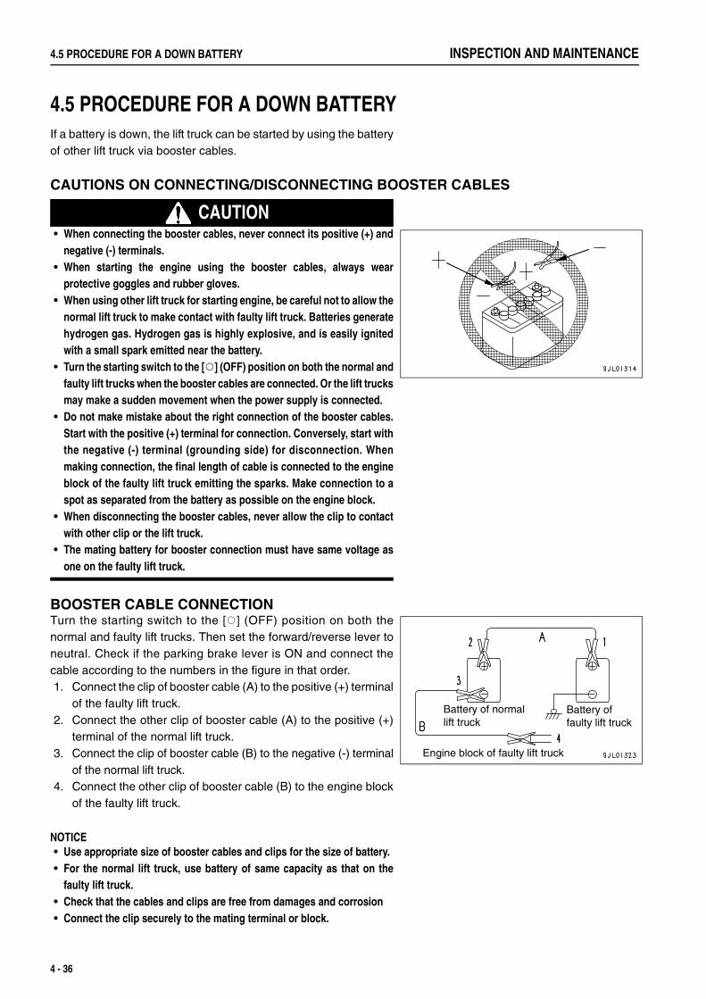
4.5 PROCEDURE FOR A DOWN BATTERY INSPECTION AND MAINTENANCE
4.5 PROCEDURE FOR A DOWN BATTERY 4
If a battery is down, the lift truck can be started by using the batteryof other lift truck via booster cables.
CAUTIONS ON CONNECTING/DISCONNECTING BOOSTER CABLES
CAUTION• When connecting the booster cables, never connect its positive (+) and
negative (-) terminals.• When starting the engine using the booster cables, always wear
protective goggles and rubber gloves.• When using other lift truck for starting engine, be careful not to allow the
normal lift truck to make contact with faulty lift truck. Batteries generatehydrogen gas. Hydrogen gas is highly explosive, and is easily ignitedwith a small spark emitted near the battery.
• Turn the starting switch to the [Q] (OFF) position on both the normal andfaulty lift trucks when the booster cables are connected. Or the lift trucksmay make a sudden movement when the power supply is connected.
• Do not make mistake about the right connection of the booster cables.Start with the positive (+) terminal for connection. Conversely, start withthe negative (-) terminal (grounding side) for disconnection. Whenmaking connection, the final length of cable is connected to the engineblock of the faulty lift truck emitting the sparks. Make connection to aspot as separated from the battery as possible on the engine block.
• When disconnecting the booster cables, never allow the clip to contactwith other clip or the lift truck.
• The mating battery for booster connection must have same voltage asone on the faulty lift truck.
BOOSTER CABLE CONNECTIONTurn the starting switch to the [Q] (OFF) position on both thenormal and faulty lift trucks. Then set the forward/reverse lever toneutral. Check if the parking brake lever is ON and connect thecable according to the numbers in the figure in that order.1. Connect the clip of booster cable (A) to the positive (+) terminal
of the faulty lift truck.2. Connect the other clip of booster cable (A) to the positive (+)
terminal of the normal lift truck.3. Connect the clip of booster cable (B) to the negative (-) terminal
of the normal lift truck.4. Connect the other clip of booster cable (B) to the engine block
of the faulty lift truck.
NOTICE• Use appropriate size of booster cables and clips for the size of battery.• For the normal lift truck, use battery of same capacity as that on the
faulty lift truck.• Check that the cables and clips are free from damages and corrosion• Connect the clip securely to the mating terminal or block.
Battery of normallift truck
Battery offaulty lift truck
Engine block of faulty lift truck
4 - 36

INSPECTION AND MAINTENANCE 4.5 PROCEDURE FOR A DOWN BATTERY
STARTING ENGINE
CAUTIONCheck if both normal and faulty lift trucks for their forward/reverse leverbeing set to the neutral position and the parking brakes to ON.
1. Check that clips are securely connected to the battery terminals.2. Start the engine on the normal lift truck and raise the speed to
full (maximum revolution).3. Turn the starting switch on the faulty lift truck to [ | ] (START) to
start engine.If the engine fails to start, try again after two minutes or over.
REMOVING THE BOOSTER CABLESWhen the engine has started, remove the booster cables inreverse order to the connection.1. Disconnect the clip of booster cable (B) from the engine block
of the faulty lift truck.2. Disconnect the clip of booster cable (B) from the negative (-)
terminal of the normal lift truck.3. Disconnect the other clip of booster cable (A) from the positive
(+) terminal of the normal lift truck.4. Disconnect the other clip of booster cable (A) from the positive
(+) terminal of the faulty lift truck.Engine block of faulty lift truck
Battery of normal lift truck
Battery of faulty lift truck
4 - 37

4.6 RUNNING IN COLD WEATHER INSPECTION AND MAINTENANCE
4.6 RUNNING IN COLD WEATHER 4
PREPARATIONS FOR LOW TEMPERATUREWhen the temperature becomes low, it becomes difficult to start the engine, and the coolant may freeze, so do asfollows.
FUEL, LUBRICANT AND HYDRAULIC OILUse fuel, lubricant and oil of low viscosity.For specified viscosity, see the "4.4.1.4 LUBRICANT LIST (DIESEL ENGINE LIFT TRUCK) (FOR EU) (PAGE 4-26)".
COOLANT
CAUTION• Supercoolant is toxic. Protect your skin and/or from it. If exposed to it, wash the skin/eye with fresh water and immediately see
a physician.• For disposing Supercoolant-added waste coolant drained during the replacement of coolant and the repair of radiator, contact
a disposal specialist or your KOMATSU FORKLIFT distributor. Supercoolant is toxic, so be sure not drain it to the drainageditch or the ground.
• Undiluted Supercoolant is flammable. Keep it away from fire. Don't smoke while handling it.
NOTICEUse Komatsu Genuine Supercoolant (AF-NAC). Other brands than Komatsu Genuine Supercoolant are not recommended asprinciple.
When the lift truck is shipped out from the factory, it is filled with Supercoolant of concentration applicable to theoutside temperature of -20°C.When the ambient temperature should fall below -20°C, raise the concentration of the coolant according to thefollowing table.
Cautions when refilling or replacing coolant• Dilute the coolant with distilled water or supply water (soft water) to an appropriate concentration for use.• Check the radiator, water pump and hoses for any water leakage.• Drain all coolant and flush the inside of the system before adding new coolant.
Diluted concentration for Supercoolant (AF-NAC)
Minimum temperature (°C) -10 -15 -20 -25 -30 -35Concentration (%) 30 35 40 45 50 55
4 - 38

INSPECTION AND MAINTENANCE 4.6 RUNNING IN COLD WEATHER
BATTERY
CAUTION• Batteries generate flammable gas. Keep it away from open flame.• Battery electrolyte is hazardous substance. Protect your skin and/or from it. If exposed to it, wash the skin/eye with large
amount of fresh water and immediately see a physician.• Battery electrolyte is hazardous substance, so be sure not drain it to the drainage ditch or the ground.• Battery electrolyte dissolves the coating. If attached to the lift truck, wash it down with water immediately.• If battery is frozen, do not charge it or start the engine using other power supply.
Or the battery may explode.
• When the temperature drops, the battery performance is deteriorated, making engine start difficult. Insufficientlycharged battery electrolyte may freeze. Get ready for the start in the following morning by charging the batteryclose to 100% at the day's end.
• Since battery performance remarkably drops as the temperature drops, remove it from the lift truck, place it ina warmer place overnight and install it the following morning. (Particularly when the temperature is low or the lifttruck is not to be used for some period)
• If the battery electrolyte level is low, refill distilled water before starting operation the next morning. To preventfreezing during the night, do not refill electrolyte after the end of operation.
REMARKFor finding the battery charge level, measure the specific gravity of battery electrolyte and convert it according tothe following table.
PRECAUTIONS AFTER COMPLETION OF OPERATIONSDrain water to prevent water deposited in the fuel pipe from freezing.For the draining of the sedimenter of diesel engine lift truck, see Section "4.4.3 FUEL FILTER WATER DRAININGAND AIR BLEEDING (DIESEL ENGINE LIFT TRUCK) (PAGE 4-29)".
WHEN COLD SEASON IS OVERWhen the weather becomes milder with the change of season, do as follows• Change oil of respective devices and fuel to those of specified viscosity according to the "LUBRICANT LIST
(PAGE 4-27)".
Electrolytetemperature (°C)
Battery chargelevel (%)
20 0 -10 -20
100 1.28 1.29 1.30 1.31
90 1.26 1.27 1.28 1.29
80 1.24 1.25 1.26 1.27
75 1.23 1.24 1.25 1.26
4 - 39

4.7 ACTION IN ENGINE OVERHEATING INSPECTION AND MAINTENANCE
4.7 ACTION IN ENGINE OVERHEATING 4
ACTION WHEN ENGINE HAS OVERHEATED
CAUTIONWhen overheated, opening the radiator reservoir tank or radiator cap immediately after stopping engine let steam spurt out tocause burns. Do not open the cap until the engine cools down.
When the engine has overheated and the coolant temperature gauge points the red range, do not panic and takethe following actions:1. Park the lift truck in a safe place.2. Keep the engine running at low idling, open the engine hood for better ventilation of the engine room.
If the cooling fan is not running, stop the engine immediately.3. When the water temperature gauge enters the white range, stop the engine.4. Check the followings after the engine has fully cooled down
• Is the coolant level right?• Is the fan belt not sheared or loosened?• Is the engine oil level right?• Isn't the radiator clogged?
5. If coolant or engine oil level is low, refill to appropriate level.In the case of other failure or the cause of overheat is unknown, contact the administrator, stop using the lifttruck and call your KOMATSU FORKLIFT distributor.
CLEANING INSIDE THE COOLING SYSTEMIf water stain and/or rust is generated inside the cooling system, cooling efficiency is deteriorated, causingoverheat.As the cooling system requires periodical inspection and washing using radiator detergent liquid, please callKOMATSU FORKLIFT distributor for maintenance service.
CLEANING OF RADIATOR FINS
CAUTION• To prevent flying objects from getting into your eyes, always wear protective glasses or goggles when cleaning.• Never direct compressed air, steam or water at yourself or any personnel as injury and/or burns may occur.
Clogged radiator fins can cause engine overheat. Clean them byblowing the air, steam or water.Set the pressure for the air or steam for blowing as describedbelow. Direct the nozzle at right angles
Air pressure : 0.98MPa ({10kgf/cm2}, 142PSI) or underSteam pressure: 0.39MPa ({4kgf/cm2}, 56.8PSI) or under
CHECK FAN BELT TENSIONIf the fan belt is loose, adjust it to the specified tension.Contact your KOMATSU FORKLIFT distributor regarding adjustment of fan belt tension.
4 - 40

INSPECTION AND MAINTENANCE 4.8 OPERATING LIFT TRUCKS IN SPECIAL ENVIRONMENT OR IN FORCIBLE WAY
4.8 OPERATING LIFT TRUCKS IN SPECIAL ENVIRONMENT OR INFORCIBLE WAY 4
This lift truck is designed and tested to cover most customers' uses under general application or environment.Under some special working environment or condition that requires mode of operation quite punishing to the lifttruck, abnormality and degradation occur to it including early failures, shorter service life, persisting failure tocertain parts and failure of usually fault-free parts and components.When the lift truck is used under special environment or in forcible way, it requires to receive maintenance andvarious other measures appropriate to a lift truck subjected to such hard and trying operating conditions. For moredetails, call your KOMATSU FORKLIFT distributor.
EXAMPLES OF SPECIAL ENVIRONMENT OR FORCIBLE USE OF LIFT TRUCK• Operating environment where the lift truck has to travel on the roads covered with salt water, chemicals (acid
and/or alkaline), solvents, etc. or it is indirectly poured or attached with them via operator's hands and feet.• Environment surrounded by corrosive gases that corrode metal and/or resin.• Environment near the sea shore blown by salty wind from the sea.• Environment where dew condensation occurs to the lift truck as it travels indoor and outdoor by getting sharp
temperature difference or environment where it is constantly soaked with water.• Environment filled with excessive sludge and those filled with dust, fine dust, and aggressive dust from polishing.• Using lift truck for other application than original designed.• Operation by which a lift truck is used for a specific work for extended span of time or used continuously in
concentration for a particular work.• Application inhibited by this operating manual.• Others
NOTICE• Operating the lift trucks in a special environment or in forcible way excludes them from the object of warranty provided by
Komatsu Ltd.• There are conditions technologies cannot cover.• This lift truck cannot be used under a condition to which a risk of explosion accompanies.
4 - 41

4.9 ACTION TO TAKE IF THE FORK FAILS TO LOWER INSPECTION AND MAINTENANCE
4.9 ACTION TO TAKE IF THE FORK FAILS TO LOWER 4
CAUTION• If the fork stops lowering during operation, stop the work immediately.
Never use this lift truck until repaired.• Put up "No Entry" and "Never use" signs to keep other persons from
entering under or in front of the raised fork.• The lift truck may suddenly start moving leading to a critical accident. Do
not touch the mast, fork, chain and other load handling devices. (Do notshake, touch or pry with a stick or tool)
• Immediately contact with the administrator or your KOMATSU FORKLIFTdistributor for repair service.
1. If the fork stops lowering during operation, stop the workimmediately.
2. Move the lift truck in question to a flat place and park it byavoiding emergency exit or fire fighting equipment. For detailson parking, see "2.5.3 STOPPING AND PARKING (PAGE 2-32)" and "3.3.8 TEMPORARY STOPPING AND PARKING(PAGE 3-30)".
3. If the loaded fork should stop operating in raised condition,secure wide "No Entry" area around the lift truck or park the lifttruck directly facing a stout wall surface in checking a risk offalling load to the ground.
Never
use
Danger
4 - 42

INSPECTION AND MAINTENANCE 4.10 WASHING LIFT TRUCK
4.10 WASHING LIFT TRUCK 4
CAUTIONIf water gets into the electrical system (controller, sensor, connector, etc.),there is a hazard that it will cause malfunctions or miss-movement. Do notuse flushing water or high- pressure steam to wash the electrical system.
Step for Washing1. Turn the starting switch key to the [Q] (OFF) position, then
remove the key.2. Wash each part ((1) to (4) parts in the figure at right), following
the instructions in the table below.3. Dry off the washed parts.4. After checking that the washed parts have dried out, insert the
starting switch key and turn it to the [ | ] (ON) position thenmake sure that there is no abnormality, and then startoperation.
No. Spot to Wash Washing Method
1 Meter PanelWash by spraying water with a hose from above.(Note) In washing, reduce the flow of water to lower water pressure as illustrated below
(only for (1) and (2) parts).
2Dashboard FrontPedalsFloor Plate
3Front & Rear TyresFront & Rear Axles
Wash with high pressure steam or flushing water from a hose.(Note) Do not use high pressure steam or flushing water for the tyre angle sensor and
electric wirings.
4Exterior parts other than the above
Wash with high pressure steam or flushing water from a hose.
Other Precautions
1. Never wash the inside of the dashboard.2. When using high pressure steam or flushing water from a hose to wash the engine
room and underpart of the floor plate (power train parts), cover the engine andtransmission including electric wirings for them, and the electric system parts likethe connector, fuse box, etc. with a tarpaulin so that those parts and componentsdo not get splashed with water.
4 - 43

4.11 LONG-TERM STORAGE INSPECTION AND MAINTENANCE
4.11 LONG-TERM STORAGE 4
Store lift trucks as follows when storing them for a long period (over one month)
BEFORE STORAGEAfter washing and cleaning respective parts, implement the following maintenance service before storing the lifttrucks indoor: If it must unavoidably be left outdoors, park the lift truck on flat ground and cover it with a tarpaulin.• Fill up the fuel tank to full. This helps prevent water deposit.• Apply grease and change oil without fail.• Fully apply grease to the exposed portions of hydraulic cylinder piston rod.• Disconnect the negative (-) terminal of the battery and cover it or remove it from the lift truck and store indoors.• To prevent freezing, add Komatsu Genuine Supercoolant (AF-NAC) (concentration 30% or upward) to the
engine coolant.
DURING STORAGE
CAUTIONIf it is necessary to carry out the rust prevention operation indoors, open the doors and windows to improve ventilation andprevent gas poisoning.
• During storage, always operate and move the lift truck once a month to retain the lubricated sections fullycovered under oil film.
• When operating work equipment, wipe the applied grease off the hydraulic cylinder piston rod.• As the battery discharges naturally, charge it once a month.
AFTER STORAGEWhen using lift trucks after some long period of storage, implement the following service before proceeding tooperation:• Wipe the applied grease off the hydraulic cylinder piston rod.• Apply grease and oil to necessary sections without fail.• When a lift truck has been in storage for a long period, moisture in the air is mixed in oil. Check oil of respective
sections before and after starting engine. If water is mixed in oil, change oil completely.
NOTICEWhen using lift trucks that were not operated once a month to prevent rusting, consult your KOMATSU FORKLIFT distributorbefore operation.
4 - 44

INSPECTION AND MAINTENANCE 4.12 HOISTING LIFT TRUCK
4.12 HOISTING LIFT TRUCK 4
CAUTION• Hook the sling to the designated holes on the top of the mast and the
counterbalance-weight.• Overhead guard and the cab mount (for a cab specification lift truck)
have no strength to hoist the lift truck. Never use them for hoisting lifttruck, or there is a danger of falling.
• Hook the sling to the mast and counterbalance-weight after checkingthat they are securely installed.
• Never allow other persons to go under or near the lifted truck.
1. The sling hooking positions are the holes on the top of theouter mast and the counterbalance-weight.
2. Check that the mast and counterbalance-weight are securelyinstalled. Tightening torque for the counterbalance-weight mount bolts.
: 441 - 639Nm {45 - 65kgfm} Tightening torque for the mast lower mount bolts.
: 157 - 196Nm {16 - 20kgfm} (AX50 Series): 343 - 427Nm {35 - 43kgfm} (BX50 Series)
3. Use undamaged sling and wire, having sufficient strength.4. When hoisting a lift truck, do not allow the overhead guard and/
or cab to make contact with wire, etc. Adjust the wire length toprevent the lift truck from being tilted. Do not give impact to itwhile hoisting.
4 - 45

4.13 LOADING AND UNLOADING OF LIFT TRUCK INSPECTION AND MAINTENANCE
4.13 LOADING AND UNLOADING OF LIFT TRUCK 4
CAUTIONThe work of loading and unloading a lift truck on a trailer always involves ahazard that the lift truck tips over or falls off if you make a mistake inhandling.Strictly follow the instructions shown below.• Stop the trailer on level, flat road surface. Apply parking brake without
fail and apply blocks to the tyres.• Use ramps or dock plate of sufficient length, width and sufficient
strength. Secure it tightly to prevent it from being dislocated ordisengaged.
• Take a right posture on the seat while operating.• If you operate the lift truck in a posture that your weight is not properly
applied to the seat, like standing up or leaning forward or sideways,travel interlock functions to cut off the transmission of engine power.Then the lift truck may slither down if the accelerator pedal is stepped onan uphill or a slope.Operate the lift truck assisted by a signal person ifnecessary so that you don't have to stand up or lean forward or sidewaysto watch. For more details on the function of travel interlocking, see"TRAVEL INTERLOCK (ENGINE POWER CUTOFF) (PAGE 3-26)".
• When using the ramp, make the gradient gentle, align the center of boththe trailer and the lift truck and lock the ramp securely to preventmisalignment.
• Never correct the course of the lift truck while on the ramps. If coursechange is required, move off the ramps once and correct the coursedirection.
1. Arrange for a trailer having adequate loading capacity for theweight and size of a lift truck to transport.
2. Stop the trailer on level, flat road surface. Apply parking brakewithout fail and apply blocks to the tyres.
3. Install the ramp, dock plate, etc. between the loading platformof the trailer and the road surface and fix it securely so that itwould not be disengaged.
4. Instruct the trailer operator not to move the trailer until loading/unloading of lift truck is completed.
5. When loading/unloading a lift truck to or from the trailer, drivethe lift truck at slow speed by sitting on the seat with rightposture.
6. To prevent a loaded lift truck from moving during transportation,apply blocks to the tyres and secure it with wire rope and/orchain before starting the trailer.
Ramp
Blocks
4 - 46

INSPECTION AND MAINTENANCE 4.14 INSPECTION AND MAINTENANCE SCHEDULE CHART
4.14 INSPECTION AND MAINTENANCE SCHEDULE CHART 4
• For other inspection and maintenance items not described in this manual, contact KOMATSU FORKLIFTdistributor.
• Incorrect inspection, maintenance and repair services may cause critical accident or shorten lift truck service life.For your safety operation, contact KOMATSU FORKLIFT distributor for inspection, maintenance and repairservices.
4 - 47

4.14 INSPECTION AND MAINTENANCE SCHEDULE CHART INSPECTION AND MAINTENANCE
INSPECTION AND MAINTENANCE SCHEDULE CHART[Q] indicates the intervals and time of inspection and maintenance by operating hours recommended by Komatsu .
Inspection & Maintenance Item
Inspection & Maintenance Intervals (hours) Replace-ment
Intervals (month)
At startupEvery 2 weeks(100h)
Every 1 month(200h)
Every 3 months(600h)
Every 6 months(1200h)
Every 1 year
(2400h)
Eng
ine
Engine proper
Startup condition & abnormal noise Q Q QOperation of preheater plug and heater Q QExhaust gas color, exhaust sound Q Q Q QIdling speed Q Q QNo-load max. speed QAcceleration Q Q QCylinder head and manifold parts bolt tightening condition QValve clearance Q QCompression pressure Q
Muffler & exhaust pipe
Gas leakage, looseness, damage QOperating condition Q
Engine mountCracking, abnormal sound, deformation, looseness and falling of bracket, damage and deterioration of vibration proof rubber
Q
Air cleaner
Contamination and damage of element Q Q QCracking, deformation and damage of case Q Q QAir cleaner element replacement Q 6
Lubrication system
Oil level and contamination Q Q QOil leakage Q Q Q QReplacement of oil in oil pan (diesel engine lift truck) Q 1Replacement of oil in oil pan(gasoline engine lift truck) (*1)
Q 500 h or3 months
Oil filter cartridge replacement (diesel engine lift truck) Q 1Oil filter cartridge replacement(gasoline engine lift truck) (*1)
Q 500 h or3 months
Fuel system
Fuel leakage Q Q QFuel filter clogging QInjection nozzle injection pressure and spray condition QFuel filter water drain (diesel engine lift truck) QFuel filter cartridge replacement (diesel engine lift truck) Q 3Fuel filter element replacement(gasoline engine lift truck) (*2)
Q 6
Fuel tank crack and damage QFuel tank oil level QFuel tank cleaning Q
Ignition system
Ignition timing Q QIgnition plug burn and damage Q Q
High-pressure fuel gas system (models with LP gas)Gas leakage, feed pipe cracking and damage, gas cylinder, looseness of mounted parts and damage
Q QPositive crankcase ventilation
Valve operation, piping clogging and damage Q
*1: Also applied to a hybrid LPG/gasoline engine lift truck and a dedicate LPG engine lift truck.*2: Also applied to a hybrid LPG/gasoline engine lift truck.
4 - 48

INSPECTION AND MAINTENANCE 4.14 INSPECTION AND MAINTENANCE SCHEDULE CHART
Inspection & Maintenance Item
Inspection & Maintenance Intervals (hours) Replace-ment
Intervals (month)
At startupEvery 2 weeks(100h)
Every 1 month(200h)
Every 3 months(600h)
Every 6 months(1200h)
Every 1 year
(2400h)
Eng
ine
Cooling system
Coolant level and contamination QWater leakage Q Q QContamination, hose damage and deterioration, radiator cap function
Q
Belt deflection, wear and damage Q Q Q QFan and cover cracking, deformation and looseness Q
Carbon monoxide emission prevention deviceMounting looseness and damage to carbon monoxide emission prevention device
QPipe damage and installation condition Q
Pow
er tr
ain
Clutch
Oil level Q Q QOperating condition Q Q QPedal play and pedal height when depressed Q Q Q QAbnormal noise, oil leakage and contamination Q QOil replacement Q 6
Transmission
Oil level Q Q Q QOil leakage and contamination Q Q Q QInching pedal operating condition QPedal height QOil replacement Q 6Strainer replacement Q 6Line filter cartridge replacement Q 6
Differential gear
Oil level Q Q Q QOil leakage and contamination Q Q QOil replacement Q 6
Shift lever
Play and engagement condition QInstallation condition Q
Forward/Reverse lever
Lighting of neutral lamp QDrive shaft
Looseness at connection Q QRunout, play, damage, cracking and bearing play Q
Ste
erin
g sy
stem
Steering wheel
Operation feel Q Q QPlay, rattle, runout, unstable driving, returning condition, wheel play and rattle
Q Q Q
Steering valve
Loose mounting QOil leakage Q Q
Rod and arm
Loosening, play and damage Q QKnuckle
Looseness at connection QKing pin play, abnormal noise, cracking, damage Q Q
Wheel
Fluctuation in min. turning radius QContact of wheel with other parts Q
4 - 49

4.14 INSPECTION AND MAINTENANCE SCHEDULE CHART INSPECTION AND MAINTENANCE
Inspection & Maintenance Item
Inspection & Maintenance Intervals (hours) Replace-ment
Intervals (month)
At startupEvery 2 weeks(100h)
Every 1 month(200h)
Every 3 months(600h)
Every 6 months(1200h)
Every 1 year
(2400h)
Ste
erin
g sy
stem
Power steering
Oil leakage Q Q QOil level Q Q QMounting condition and loosening at connection QHose pipe damage Q Q
Bra
king
sys
tem
Brake pedal
Stroke and braking effect Q Q QPlay and pedal height when depressed Q Q QInching pedal operation Q
Parking Brake
Operating effort Q Q QBraking effect Q Q Q
Rod, cable and link
Looseness, play, damage, wear and missing cotter pin QHose and piping
Leakage, damage and installation condition Q Q QReservoir tank
Oil level Q Q QContamination Q QOil replacement Q Q 6
Master cylinder and wheel cylinder
Operating condition, wear and damage QOil leakage Q
Servo system
Operating condition QBrake drum and bake shoe
Clearance between drum and lining Q QShoe and lining wear QDrum wear and damage QDrum mount bolts looseness QBacking plate cracking, damage, deformation and bolt looseness
Q
Brake spring deterioration, and anchor pin corrosion QWork equipment operating condition Q Q Q
Load
ing
equi
pmen
t
Fork
Fork and fork stopper deformation, crack and damage Q Q QCracking and wear at fork bottom and upper and lower hooks (by dye penetration check)
Q
Opening, level difference and bend at fork tips QMast and lift brackets
Deformation, crack and damage Q Q QRoller wear, play, and pin cracking QMast support portion play, and cap mounting bolt looseness
Q
Chain and chain wheel
Chain cracking, deformation, damage and corrosion QChain wheel deformation, damage and play QChain tension Q Q QChain elongation QChain lubrication Q Q 100
Load backrest
Mounting bolt looseness, cracking, damage and deformation
Q Q Q
Looseness of tilt cylinder rod and locknut Q
4 - 50

INSPECTION AND MAINTENANCE 4.14 INSPECTION AND MAINTENANCE SCHEDULE CHART
Inspection & Maintenance Item
Inspection & Maintenance Intervals (hours) Replace-ment
Intervals (month)
At startupEvery 2 weeks(100h)
Every 1 month(200h)
Every 3 months(600h)
Every 6 months(1200h)
Every 1 year
(2400h)
Hyd
raul
ic s
yste
m
Hydraulic pump
Oil leakage, abnormal vibration and noise Q QLift cylinder and tilt cylinder
Operating condition and oil leakage Q Q QDents, cracking, bends, scratches, and mounting bolt looseness
Q Q
Cylinder drift and tilt by itself QDirectional control valve
Operating condition and oil leakage Q Q QPlay and mounting bolt looseness Q QRelief pressure Q
Hydraulic oil
Hydraulic oil tank damage and cracks QOil replacement Q 6Tank oil level, contamination and oil leakage Q Q QTank cleaning QAir breather replacement Q 12Line filter replacement Q 6Strainer cleaning Q
Piping
Piping damage, oil leakage and deformation Q Q QPiping clip loosening and slipping off Q QSolenoid valve operation, abnormal noise, abnormal heat and oil leakage
Q
Ele
ctric
sys
tem
Charging system function QBattery
Electrolyte level Q Q QLooseness and corrosion of terminal connection Q
Wiring
Looseness and damages at connection Q Q
Trav
elin
g eq
uipm
ent
Front axle
Axle cracks, damage and deformation, and mounting bolt looseness
Q
Rear axle
Axle cracks, damage and deformation, and mounting bolt looseness
Q
Center pin play, and cap mounting bolt looseness QWheel
Tyre inflation pressure Q Q QTyre crack and damage Q Q QTyre tread depth and abnormal wear Q Q QTyre condition QPlay and abnormal noise of front wheel bearing Q QPlay and abnormal noise of rear wheel bearing Q QLooseness of wheel nut and bolt Q Q QDisc and wheel deformation, cracking and damage Q Q
4 - 51

4.14 INSPECTION AND MAINTENANCE SCHEDULE CHART INSPECTION AND MAINTENANCE
Inspection & Maintenance Item
Inspection & Maintenance Intervals (hours) Replace-ment
Intervals (month)
At startupEvery 2 weeks(100h)
Every 1 month(200h)
Every 3 months(600h)
Every 6 months(1200h)
Every 1 year
(2400h)
Saf
ety
devi
ces,
cha
ssis
, etc
.
Main Body
Looseness and damage of mounting bolt and nut QCracks and deformation Q
Overhead guard
Looseness, deformation, damage and cracking of mounting bolt
Q Q Q
Looseness and damage of each part QSeat
Seat operation, looseness and damage of mounting bolt, and seat belt damage
Q QOperating condition of seat belt lock Q QFunction of buckle or retractor Q Q QOpen seam of seat belt webbing Q Q
Turn signal lamp
Lighting and flashing operations, contamination and damage
Q Q Q
Alarms
Operation, sound volume and tone Q Q QLighting device
Operating condition (Head lamp, clearance lamp, brake lamp and backup lamp)
Q Q QInstrument operating condition, installation condition, breakage and water entry
Q Q Q
Rear view mirror
Contamination, damage, reflection and installation condition
Q Q Q
Lubrication Q Q QBackup buzzer performance QDisplay board damage and installation condition QAbnormality found on preceding day QSafety device performance
(Travel interlock, lift interlock and neutral safety) QParking brake reminder buzzer Q
Com
preh
ensi
ve te
st Operation of various devices Q Q Q Q QAbnormal vibration, noise, odor and heating Q
4 - 52

INSPECTION AND MAINTENANCE 4.15 PERIODIC REPLACEMENT OF SAFETY CRITICAL PARTS
4.15 PERIODIC REPLACEMENT OF SAFETY CRITICAL PARTS 4
For your safety use of lift trucks, you are requested to always implement periodic replacement of parts listed in thePeriodic Replacement of Safety Critical Parts below related particularly to the safety and fires.The material of these parts may change over time, or may easily wear or deteriorate. However, as it is difficult tojudge the condition of the parts simply by periodic maintenance, they should always be replaced after a fixed timehas passed, regardless of their condition. This is necessary to ensure that their full function is always maintained.However, if these parts show any abnormality before the replacement interval has passed, they should be repairedor replaced immediately.If the hose clamps show any sign of deterioration such as deformation or cracking, replace them with the hoses atthe same time.Note that the periodic replacement is not covered by warranty.
IMPORTANT PARTS LIST
No. Part name Years elapsed1 Master cylinder, wheel cylinder cup and dust seal, etc. 1
2 Rubber parts for brake booster 1
3 Brake hose or tube 2
4 Reservoir tank and tube 2
5 Power steering hose 2
6 Stop lamp switch (hydraulic type) 2
7 Fuel hose 2
8 Rubber parts inside power steering system 2
9 Lift chain 2 - 4
10 Hydraulic hose (for travel, loading & unloading and torque converter) 2
4 - 53

4.16 SERVICE DATA INSPECTION AND MAINTENANCE
4.16 SERVICE DATA 4
SERVICE DATA (GASOLINE ENGINE LIFT TRUCK)Component Inspection item Unit FG10/15/18-21 FG15H/18H-21
Eng
ine
Engine proper
Engine model – NISSAN K15 NISSAN K21
Idling speed rpm 750 - 900 750 - 900Max. speed rpm 2900 - 3100 2900 - 3100
CompressionMPa (PSI)
{kgf/cm2}/rpm1.27 (185) {13.0} / 250 1.23 (177) {12.5} / 250
Lubricating oil cooling system
Fan belt deflection mm(98N{10kgf}by finger force)
mm (in)11 - 13
(0.43 - 0.51)11 - 13
(0.43 - 0.51)
Fuel system
Injection timing deg-BTDC – –Injection order – – –
Injection pressureMPa (PSI){kgf/cm2}
– –
Intake, exhaust system
ValveClearance
Intake mm (in) 0.38 (0.015) [Warm] 0.38 (0.015) [Warm]Exhaust mm (in) 0.38 (0.015) [Warm] 0.38 (0.015) [Warm]
Electric system
Distributor point gap – – –Spark plug gap mm (in) 0.8 - 0.9 (0.031 - 0.035) 0.8 - 0.9 (0.031 - 0.035)Spark plug type – FR2A - D FR2A - D
Ignition timing deg-BTDC/rpm 4 / 850 2 / 850Firing order – 1 - 3 - 4 - 2 1 - 3 - 4 - 2
Trav
el S
yste
m TyresTyre inflation
pressure
Front wheelskPa (PSI){kgf/cm2}
700 (101) {7.1} 700 (101) {7.1}
Rear wheelskPa (PSI){kgf/cm2}
800 (116) {8.2} 800 (116) {8.2}
Hub nutTightening
torqueFront wheels Nm {kgfm} 157 - 245 {16 - 25} 157 - 245 {16 - 25}
Rear wheels Nm {kgfm} 83 - 147 {8.5 - 15} 83 - 147 {8.5 - 15}
Rim mating nuts
Tightening torque
Front wheels Nm {kgfm} 88 - 123 {9.0 - 12.5} 88 - 123 {9.0 - 12.5}Rear wheels Nm {kgfm} 59 - 74 {6.0 - 7.5} 59 - 74 {6.0 - 7.5}
Ste
erin
g, b
raki
ng s
yste
m
Steering wheel
Play (At the time of a pump operation)
mm (in) 10 - 30 (0.4 - 1.2) 10 - 30 (0.4 - 1.2)
Clutch pedal Play mm (in) 0 - 4 (0 - 0.158) 0 - 4 (0 - 0.158)
Inching pedal
Play mm (in) 0 - 4 (0 - 0.158) 0 - 4 (0 - 0.158)Interconnected stroke mm (in) 35 - 41 (1.38 - 1.61) 35 - 41 (1.38 - 1.61)
Brake pedalPlay mm (in) 0 - 4 (0 - 0.158) 0 - 4 (0 - 0.158)
Pedal height when pedal is depressed
mm (in) 76 - 96 (3.0 - 3.8) 76 - 96 (3.0 - 3.8)
BRAKE
Parking brake operating force
N {kgf} 147 - 196 {15 - 20} 147 - 196 {15 - 20}
Tightening torque for back plate mounting bolts
Nm {kgfm} 176 - 196 {18 - 20} 176 - 196 {18 - 20}
Load
ing
equi
pmen
t
Fork Fork thickness at base mm (in)1.0 ton lift truck : Min. 26 (1.02)1.5 ton lift truck : Min. 30 (1.18)1.75 ton lift truck: Min. 33 (1.30)
Chain Length over 17 links mm (in) Max. 275.5 (10.8) Max. 275.5 (10.8)
Hydraulic system
Relief pressureMPa (PSI){kgf/cm2}
17.2 (2490) {175} 17.2 (2490) {175}
4 - 54

INSPECTION AND MAINTENANCE 4.16 SERVICE DATA
*1: Use BP4ES for lift trucks of LPG specifications to prevent engine knocking and run-on.*2: Power brake-installed lift truck: 245 - 294N (25 - 30kgf).
Component Inspection item Unit FG20/25-17 FG20H/25H-17 FG20N/25N-17
Eng
ine
Engine proper
Engine model – NISSAN K21 NISSAN K25 NISSAN K21
Idling speed rpm 750 - 900 750 - 900 750 - 900Max. speed rpm 2900 - 3100 2720 - 2920 2900 - 3100
CompressionMPa (PSI)
{kgf/cm2}/rpm1.23 (177)
{12.5} / 2501.27 (185)
{13.0} / 2501.23 (177)
{12.5} / 250
Lubricating oil cooling
system
Fan belt deflection mm(98N{10kgf} by finger force)
mm (in)11 - 13
(0.43 - 0.51)11 - 13
(0.43 - 0.51)11 - 13
(0.43 - 0.51)
Fuel system
Injection timing deg-BTDC – – –Injection order – – – –
Injection pressure MPa (PSI) {kgf/cm2} – – –
Intake, exhaust system
Valve clearance
Intake mm (in)0.38 (0.015)
[Warm]0.38 (0.015)
[Warm]0.38 (0.015)
[Warm]
Exhaust mm (in)0.38 (0.015)
[Warm]0.38 (0.015)
[Warm]0.38 (0.015)
[Warm]
Electric system
Distributor point gap – – – –
Spark plug gap mm (in)0.8 - 0.9
(0.031 - 0.035)0.8 - 0.9
(0.031 - 0.035)0.8 - 0.9
(0.031 - 0.035)Spark plug type – FR2A - D(*1) FR2A - D(*1) FR2A - D(*1)
Ignition timing deg-BTDC/rpm 2 / 850 0 / 850 2 / 850Firing order – 1 - 3 - 4 - 2 1 - 3 - 4 - 2 1 - 3 - 4 - 2
Trav
el S
yste
m
TyresTyre inflation
pressureFront wheels kPa (PSI) {kgf/cm2} 700 (101) {7.1} 700 (101) {7.1} -
Rear wheels kPa (PSI) {kgf/cm2} 700 (101) {7.1} 700 (101) {7.1} -
Hub nutTightening
torque
Front wheels Nm {kgfm}294 - 490{30 - 50}
294 - 490{30 - 50}
294 - 490{30 - 50}
Rear wheels Nm {kgfm}157 - 245{16 - 25}
157 - 245{16 - 25}
157 - 245{16 - 25}
Rim boltTightening
torque
Front wheels Nm {kgfm} 196 - 294 {20 - 30} –
Rear wheels Nm {kgfm}88 - 123{9 - 12.5}
88 - 123{9 - 12.5}
–
Ste
erin
g, b
raki
ng s
yste
m
Steering wheel
Play mm (in) 10 - 30 (0.4 - 1.2) 10 - 30 (0.4 - 1.2) 10 - 30 (0.4 - 1.2)
Clutch pedal Play mm (in) 0 - 4 (0 - 0.158) 0 - 4 (0 - 0.158) –
Inching pedal
Play mm (in) 0 - 4 (0 - 0.158) 0 - 4 (0 - 0.158) 0 - 4 (0 - 0.158)
Interconnected stroke mm (in)35 - 41
(1.38 - 1.61)35 - 41
(1.38 - 1.61)35 - 41
(1.38 - 1.61)
Brake pedalPlay mm (in) 0 - 4 (0 - 0.158) 0 - 4 (0 - 0.158) 0 - 4 (0 - 0.158)
Pedal height when pedal is depressed
mm (in) 62 - 82 (2.4 - 3.2) 62 - 82 (2.4 - 3.2) 62 - 82 (2.4 - 3.2)
BRAKE
Parking brake operating force
N {kgf}147 - 196
{15 - 20}(*2)147 - 196
{15 - 20}(*2)147 - 196
{15 - 20}(*2)Back plate mounting bolt
tightening torqueNm {kgfm}
176 - 196{18 - 20}
176 - 196{18 - 20}
176 - 196{18 - 20}
Load
ing
equi
pmen
t
Fork Fork thickness (at base) mm (in)2 ton lift truck : Min. 32.5 (1.28)2.5 ton lift truck : Min. 36 (1.42)
Chain Length over 17 links mm (in) 2 - 2.5 ton lift truck : Max. 330 (13.0)
Hydraulic system
Relief pressure MPa (PSI) {kgf/cm2} 18 (2630) {185} 18 (2630) {185} 18 (2630) {185}
4 - 55

4.16 SERVICE DATA INSPECTION AND MAINTENANCE
*1: Use BP4ES for lift trucks of LPG specifications to prevent engine knocking and run-on.*2: Power brake-installed lift truck: 245 - 294N (25 - 30kgf).
Component Inspection item Unit FG30-17 FG30N-17 FG35A-17
Eng
ine
Engine proper
Engine model – NISSAN K25 NISSAN K25 NISSAN K25
Idling speed rpm 750 - 900 750 - 900 750 - 900Max. speed rpm 2720 - 2920 2720 - 2920 2720 - 2920
CompressionMPa (PSI)
{kgf/cm2}/rpm1.27 (185)
{13.0} / 2501.27 (185)
{13.0} / 2501.27 (185)
{13.0} / 250
Lubricating oil cooling
system
Fan belt deflection mm(98N{10kgf}by finger force)
mm (in)11 - 13
(0.43 - 0.51)11 - 13
(0.43 - 0.51)11 - 13
(0.43 - 0.51)
Fuel system
Injection timing deg-BTDC – – –Injection order – – – –
Injection pressure MPa (PSI) {kgf/cm2} – – –
Intake, exhaust system
Valve clearance
Intake mm (in)0.38 (0.015)
[Warm]0.38 (0.015)
[Warm]0.38 (0.015)
[Warm]
Exhaust mm (in)0.38 (0.015)
[Warm]0.38 (0.015)
[Warm]0.38 (0.015)
[Warm]
Electric system
Distributor point gap – – – –
Spark plug gap mm (in)0.8 - 0.9
(0.031 - 0.035)0.8 - 0.9
(0.031 - 0.035)0.8 - 0.9
(0.031 - 0.035)Spark plug type – FR2A - D(*1) FR2A - D(*1) FR2A - D(*1)
Ignition timing deg-BTDC/rpm 0 / 850 0 / 850 0 / 850Firing order – 1 - 3 - 4 - 2 1 - 3 - 4 - 2 1 - 3 - 4 - 2
Trav
el S
yste
m
TyresTyre inflation
pressureFront wheels kPa (PSI) {kgf/cm2} 700 (101) {7.1} – 850 (121) {8.5}
Rear wheels kPa (PSI) {kgf/cm2) 700 (101) {7.1} – 900 (130) {9.2}
Hub nutTightening
torque
Front wheels Nm {kgfm}294 - 490{30 - 50}
294 - 490{30 - 50}
294 - 490{30 - 50}
Rear wheels Nm {kgfm}157 - 245{16 - 25}
157 - 245{16 - 25}
157 - 245{16 - 25}
Rim boltTightening
torqueFront wheels Nm {kgfm} – – –Rear wheels Nm {kgfm} – – –
Ste
erin
g, b
raki
ng s
yste
m
Steering wheel
Play mm (in) 10 - 30 (0.4 - 1.2) 10 - 30 (0.4 - 1.2) 10 - 30 (0.4 - 1.2)
Clutch pedal Play mm (in) – – –
Inching pedal
Play mm (in) 0 - 4 (0 - 0.158) 0 - 4 (0 - 0.158) 0 - 4 (0 - 0.158)
Interconnected stroke mm (in)35 - 41
(1.38 - 1.61)35 - 41
(1.38 - 1.61)40 - 46
(1.58 - 1.81)
Brake pedalPlay mm (in) 0 - 4 (0 - 0.158) 0 - 4 (0 - 0.158) 0 - 4 (0 - 0.158)
Pedal height when pedal is depressed
mm (in) 62 - 82 (2.4 - 3.2) 62 - 82 (2.4 - 3.2) 62 - 82 (2.4 - 3.2)
BRAKE
Parking brake operating force
N {kgf}147 - 196
{15 - 20}(*2)147 - 196
{15 - 20}(*2)147 - 196
{15 - 20}(*2)
Back plate mounting bolt tightening torque
Nm {kgfm}176 - 196{18 - 20}
176 - 196{18 - 20}
245 - 294{25 - 30}
Load
ing
equi
pmen
t
Fork Fork thickness at base mm (in)3 ton lift truck : Min. 39.5 (1.60)3.5 ton lift truck: Min. 45 (1.80)
Chain Length over 17 links mm (in)3 ton lift truck : Max. 550 (21.7)3.5 ton lift truck: Max. 440 (17.3)
Hydraulic system
Relief pressureMPa (PSI){kgf/cm2}
18 (2630) {185} 18 (2630) {185} 18 (2630) {185}
4 - 56

INSPECTION AND MAINTENANCE 4.16 SERVICE DATA
SERVICE DATA (DIESEL ENGINE LIFT TRUCK)Component Inspection item Unit FD10/15/18-21
Eng
ine
Engine proper
Engine model – Komatsu 4D92EIdling speed rpm 785 - 835Max. speed rpm 2700 - 2750
Compression MPa (PSI) {kgf/cm2}/rpm 2.94 (426) {30} / 250
Lubricating oil cooling
system
Fan belt deflection mm(98N{10kgf} by finger force)
mm (in) 10 - 15 (0.39 - 0.59)
Fuel system
Injection timing deg-BTDC ATDC4
Injection order – 1 - 3 - 4 - 2
Injection pressure MPa (PSI) {kgf/cm2} 12.7 (1850) {130}
Intake, exhaust system
Valve clearance
Intake mm (in) 0.2 (Cold)
Exhaust mm (in) 0.2 (Cold)
Electric system
Distributor point gap mm (in) –
Spark plug gap mm (in) –Ignition timing deg-BTDC/rpm –Ignition order – –
Trav
el S
yste
m TyresTyre inflation
pressureFront wheels kPa (PSI) {kgf/cm2} 700 (101) {7.1}
Rear wheels kPa (PSI) {kgf/cm2} 800 (116) {8.2}
Hub nutTightening
torqueFront wheels Nm {kgfm} 157 - 245 {16 - 25}
Rear wheels Nm {kgfm} 83 - 147 {8.5 - 15}
Rim mating bolts
Tightening torque
Front wheels Nm {kgfm} 88 - 123 {9.0 - 12.5}Rear wheels Nm {kgfm} 59 - 74 {6.0 - 7.5}
Ste
erin
g, b
raki
ng s
yste
m
Steering wheel
Play (At the time of a pump operation)
mm (in) 10 - 30 (0.4 - 1.2)
Clutch pedal
Play mm (in) 0 - 4 (0 - 0.158)
Inching pedal
Play mm (in) 0 - 4 (0 - 0.158)Interconnected stroke mm (in) 36 - 40 (1.42 - 1.58)
Brake pedalPlay mm (in) 0 - 4 (0 - 0.158)
Pedal height when pedal is depressed
mm (in) 76 - 96 (3.0 - 3.8)
BRAKE
Parking brake operating force
N {kgf} 147 - 196 {15 - 20}
Back plate mounting bolt tightening torque
Nm {kgfm} 176 - 196 {18 - 20}
Load
ing
equi
pmen
t
Fork Fork thickness at base mm (in)1.0 ton lift truck : Min. 26 (1.02)1.5 ton lift truck : Min. 30 (1.18)1.75 ton lift truck: Min. 33 (1.30)
Chain Length over 17 links mm (in) Max. 275.5 (10.8)
Hydraulic system
Relief pressure MPa (PSI) {kgf/cm2} 17.2 (2490) {175}
4 - 57

4.16 SERVICE DATA INSPECTION AND MAINTENANCE
*1: FD35A: 40 - 46 mm (1.6 - 1.8 in).*2: FD35A and power brake-installed lift truck: 245 - 294N (25 - 30kgf).
Component Inspection item Unit FD20/25/30-17
Eng
ine
Engine proper
Engine model – Komatsu 4D94LE
Idling speed rpm 785 - 835Max. speed rpm 2425 - 2475
CompressionMPa (PSI)
{kgf/cm2}/rpm2.94 (426){30} / 250
Lubricating oil cooling
system
Fan belt deflection mm(98N{10kgf}by finger force)
mm (in)10 - 15
(0.39 - 0.59)
Fuel system
Injection timing deg-BTDC ATDC4Injection order – 1 - 3 - 4 - 2
Injection pressureMPa (PSI) {kgf/cm2}
12.7 (1850) {130}
Intake, exhaust system
Valve clearance
Intake mm (in) 0.2 (0.0079) [Cool]
Exhaust mm (in) 0.2 (0.0079) [Cool]
Electric system
Distributor point gap mm (in) –
Spark plug gap mm (in) –Ignition timing deg-BTDC/rpm –Ignition order – –
Trav
el S
yste
m
TyresTyre inflation
pressure
Front wheelskPa (PSI) {kgf/cm2}
700 (101) {7.1}
Rear wheelskPa (PSI) {kgf/cm2}
700 (101) {7.1}
Hub nutTightening
torque
Front wheels Nm {kgfm}294 - 490{30 - 50}
Rear wheels Nm {kgfm}157 - 245{16 - 25}
Rim boltTightening
torqueFront wheels Nm {kgfm}
196 - 294 {20 - 30}[except 3 ton lift truck]
Rear wheels Nm {kgfm} 88 - 123 {9 - 12.5}
Ste
erin
g, b
raki
ng s
yste
m
Steering wheel
Play mm (in) 10 - 30 (0.4 - 1.2)
Clutch pedal Play mm (in) 0 - 4 (0 - 0.158)
Inching pedal
Play mm (in) 0 - 4 (0 - 0.158)
Interconnected stroke mm (in)36 - 40
(1.42 - 1.58)
Brake pedalPlay mm (in) 0 - 4 (0 - 0.158)
Pedal height when pedal is depressed
mm (in) 62 - 82 (2.4 - 3.2)
BRAKE
Parking brake operating force
N {kgf}147 - 196{15 - 20}
Back plate mounting bolt tightening torque
Nm {kgfm}176 - 196{18 - 20}
Load
ing
equi
pmen
t
Fork Fork thickness at base mm (in)
2 ton lift truck : Min. 32.5 (1.28)2.5 ton lift truck : Min. 36 (1.42)3 ton lift truck : Min. 39.5 (1.56)3.5 ton lift truck : Min. 45 (1.80)
Chain Length over 17 links mm (in)2 - 2.5 ton lift truck: Max. 330 (13.0)3 ton lift truck : Max. 550 (21.7)3.5 ton lift truck : Max. 440 (17.3)
Hydraulic system
Relief pressureMPa (PSI) {kgf/cm2}
18.1 (2630) {185}
4 - 58

INSPECTION AND MAINTENANCE 4.16 SERVICE DATA
*1: FD35A: 850 kPa (121 PSI) {8.5 kgf/cm2}.*2: FD35A: 900 kPa (130 PSI) {9.2 kgf/cm2}.*3: FD35A: 40 - 46 mm (1.58 - 1.81 in).*4: FD35A: 245 - 294N (25 - 30kgf).
Component Inspection item Unit FD20H/25H/30H/35A-17
Eng
ine
Engine proper
Engine model – Komatsu 4D98EIdling speed rpm 820 - 870
Max. speed rpm 2700 - 2750
CompressionMPa (PSI)
{kgf/cm2}/rpm2.94 (426) {30} / 250
Lubricating oil cooling
system
Fan belt deflection mm(98N{10kgf}by finger force)
mm (in) 10 - 15 (0.39 - 0.59)
Fuel system
Injection timing deg-BTDC ATDC11Injection order – 1 - 3 - 4 - 2
Injection pressureMPa (PSI) {kgf/cm2}
12.7 (1850) {130}
Intake, exhaust system
Valve clearance
Intake mm (in) 0.2 (0.0079) [Cool]
Exhaust mm (in) 0.2 (0.0079) [Cool]
Electric system
Distributor point gap mm (in) –Spark plug gap mm (in) –
Ignition timing deg-BTDC/rpm –Ignition order – –
Trav
el S
yste
m
TyresTyre inflation
pressure
Front wheelskPa (PSI) {kgf/cm2}
700 (101) {7.1} (*1)
Rear wheelskPa (PSI) {kgf/cm2}
700 (101) {7.1} (*2)
Hub nutTightening
torqueFront wheels Nm {kgfm} 294 - 490 {30 - 50}
Rear wheels Nm {kgfm} 157 - 245 {16 - 25}
Rim boltTightening
torqueFront wheels Nm {kgfm}
196 - 294 {20 - 30}[except 3 ton lift truck]
Rear wheels Nm {kgfm} 88 - 123 {9 - 12.5}
Ste
erin
g, b
raki
ng s
yste
m
Steering wheel
Play mm (in) 10 - 30 (0.4 - 1.2)
Clutch pedal Play mm (in) 0 - 4 (0 - 0.158)
Inching pedal
Play mm (in) 0 - 4 (0 - 0.158)Interconnected stroke mm (in) 36 - 40 (1.42 - 1.58) (*3)
Brake pedalPlay mm (in) 0 - 4 (0 - 0.158)
Pedal height when pedal is depressed
mm (in) 62 - 82 (2.4 - 3.2)
BRAKE
Parking brake operating force
N {kgf} 147 - 196 {15 - 20} (*4)
Back plate mounting bolt tightening torque
Nm {kgfm} 176 - 196 {18 - 20}
Load
ing
equi
pmen
t
Fork Fork thickness at base mm (in)
2 ton lift truck : Min. 32.5 (1.28)2.5 ton lift truck : Min. 36 (1.42)3 ton lift truck : Min. 39.5 (1.56)3.5 ton lift truck : Min. 45 (1.80)
Chain Length over 17 links mm (in)2 - 2.5 ton lift truck: Max. 330 (13.0)3 ton lift truck : Max. 550 (21.7)3.5 ton lift truck : Max. 440 (17.3)
Hydraulic system
Relief pressureMPa (PSI) {kgf/cm2}
18.1 (2630) {185}
4 - 59

4.16 SERVICE DATA INSPECTION AND MAINTENANCE
BOLT TIGHTENING TORQUE• For unspecified metric bolts and nuts, use the torques specified
in this list.• Select a proper torque corresponding to the width across flats
(b) of bolts and nuts.• When replacing bolts and nuts, always use Komatsu Genuine
Parts of the same size as the previous ones.
Thread outside diameter (a) mm
Width across flat (b) mm
Tightening torque Nm {kgfm}
Within target allowable range6 10 13 {1.35} 12 - 15 {1.2 - 1.5}8 13 31 {3.2} 27 - 34 {2.8 - 3.5}
10 17 66 {6.7} 59 - 74 {6.0 - 7.5}12 19 113 {11.5} 98 - 123 {10.0 - 12.5}14 22 177 {18.0} 157 - 196 {16.0 - 20.0}
16 24 279 {28.5} 245 - 309 {25.0 - 31.5}18 27 382 {39.0} 343 - 427 {35.0 - 43.5}
20 30 549 {56.0} 490 - 608 {50.0 - 62.0}22 32 745 {76.0} 662 - 829 {67.5 - 84.5}24 36 927 {94.5} 824 - 1030 {84.0 - 105.0}
27 41 1324 {135.0} 1177 - 1471 {120.0 - 150.0}30 46 1716 {175.0} 1520 - 1912 {155.0 - 195.0}33 50 2206 {225.0} 1961 - 2452 {200.0 - 250.0}
36 55 2746 {280.0} 2452 - 3040 {250.0 - 310.0}39 60 3285 {335.0} 2893 - 3628 {295.0 - 370.0}
4 - 60

5 - 1
TECHNICAL DATA 5
55

5. TECHNICAL DATA TECHNICAL DATA
5 - 2
5. TECHNICAL DATA 5

TECHNICAL DATA 5. TECHNICAL DATA
5 - 3
AX50 (1.0 ton) Series
Cha
ract
eris
tics
1.2 Model Manufacturer's Designation FG10T-21 FG10C-21 FD10T-21 FD10C-21
1.3 Power Type Electric, Diesel, Gasoline, LPG Gasoline Diesel
1.4 Operation Type Sitting Sitting
1.5 Rated Capacity Rated Capacity kg 1000 1000
1.6 Load Center Rated Load Center mm 500 500
1.6.1 Alternative Capacity Capacity@600mm Load Center kg 910 910
1.8 Load Distance xFront Axle Center to Fork Face
mm 400 400
1.9 Wheelbase y mm 1400 1400
Wei
ght
2.1 Service Weight kg 2080 2120 2180 2220
2.2
Axle Loading
LoadedFront kg 2725 2735 2760 2765
2.2.1 Rear kg 355 360 420 430
2.3Unloaded
Front kg 1065 1075 1095 1105
2.3.1 Rear kg 1015 1020 1085 1090
Tyre
s
3.1 Tyre Type Pneumatic Pneumatic
3.2Tyre Size
Front 6.50-10-10PR(I) 6.50-10-10PR(I)
3.3 Rear 5.00- 8- 8PR(I) 5.00- 8- 8PR(I)
3.5 Number of Wheel Front/Rear (x=driven) 2*/2 2*/2
3.6 Tread, Front b4 mm 890 890
3.7 Tread, Rear b3 mm 895 895
Dim
ensi
ons
4.1 Tilting Angle α/β Forward/Backward degree 6/10 6/10
4.2 Mast Height, Lowered h1 2-stage Mast mm 1995 1995
4.3 Std. Free Lift h22-stage Std. Mast, from Ground
mm 135 135
4.4 Std. Lift Height h32-stage Std. Mast, from Ground
mm 3000 3000
4.5 Mast Height, Extended h4 2-stage Std. Mast mm 3955 3955
4.7 Height, Overhead Guard h6 mm 2070 2070
4.19 Length, with Std. Forks L1 mm 2965 2965
4.20 Length, to Fork Face L2 mm 2195 2195
4.21 Width, at Tyre b1 Single mm 1070 1070
4.22 Forks Thickness x Width x Length mm 31x100x770 31x100x770
4.23 Fork Carriage Class ISO 2328, Type A/B/no Class 2 Class 2
4.24 Width, Fork Carriage b2 mm 970 970
4.31Ground Clearance
m1 Under Mast mm 120 120
4.32 m2 at Center of Wheelbase mm 130 130
4.33Right Angle Stacking Aisle
with L1000 x W1200 pallet mm 3315 3315
4.34 with L1200 x W800 pallet mm 3515 3515
4.35 Turning Radius Wa mm 1915 1915
Per
form
ance
5.1 Travel Speed (FWD)Loaded, 1st/2nd km/h 19.0 9.0/19.0 19.0 8.5/19.0
Unloaded, 1st/2nd km/h 19.0 9.0/19.0 19.5 8.5/19.5
5.2 Lifting SpeedLoaded mm/s 580 620
Unloaded mm/s 640 670
5.3 Lowering SpeedLoaded mm/s 500 500
Unloaded mm/s 550 550
5.6 Max. Drawbar Pull Loaded KN 10 11 13 14
5.8 Max. Gradeability Loaded % 34 38 49 41
5.10 Service Brake Operation/Control Foot/Hydraulic Foot/Hydraulic
5.11 Parking Brake Operation/Control Hand/Mechanical Hand/Mechanical
5.12 Steering Type FHPS FHPS
6.4 Battery Voltage/ Capacity at 5-hour rating V/ah 12/33 12/64
I.C E
ngin
e
7.1 Maker Model NISSAN K15 Komatsu 4D92E
7.2 Rated Output, SAE gross KW 27@2500 35@2450
7.3 Rated RPM min-1 2500 2450
7.3.1 Max. Torque, SAE gross Nm@min-1 113@1600 142@1800
7.4 No. of Cylinder/Displacement cm3 4-1486 4-2659
Oth
ers 7.6 Fuel Tank Capacity Ltr 40 40
8.2 Relief Pressure for Attachment bar 172 172
8.7 Transmission TORQFLOW Manual TORQFLOW Manual
Noi
se L
evel LpAZ as Measured in accordance with EN12053 dB(A) 82 84
KPZ The uncertainty of measurement in accordance with EN12053 2.5 2.5
LWAd Guaranteed sound power level accordance with 2000/14/EC dB(A) 105 106
The uncertainty of measurement 2.1 1.3
Vib
ratio
n VIBRATION in accordance with EN 13059 m/s2 0.7 0.7
The uncertainty of measurement 0.4 0.4

5. TECHNICAL DATA TECHNICAL DATA
5 - 4
AX50 (1.5 ton) Series
Cha
ract
eris
tics
1.2 Model Manufacturer's Designation FG15T-21 FG15C-21 FD15T-21 FD15C-21 FG15HT-21 FG15HC-21
1.3 Power Type Electric, Diesel, Gasoline, LPG Gasoline Diesel Gasoline
1.4 Operation Type Sitting Sitting Sitting
1.5 Rated Capacity Rated Capacity kg 1500 1500 1500
1.6 Load Center Rated Load Center mm 500 500 500
1.6.1 Alternative Capacity Capacity@600mm Load Center kg 1360 1360 1360
1.8 Load Distance xFront Axle Center to Fork Face
mm 405 405 405
1.9 Wheelbase y mm 1400 1400 1400
Wei
ght
2.1 Service Weight kg 2450 2490 2550 2590 2450 2490
2.2
Axle Loading
LoadedFront kg 3500 3510 3530 3540 3500 3510
2.2.1 Rear kg 450 455 520 525 450 455
2.3Unloaded
Front kg 1005 1015 1035 1045 1005 1015
2.3.1 Rear kg 1445 1450 1515 1520 1445 1450
Tyre
s
3.1 Tyre Type Pneumatic Pneumatic Pneumatic
3.2Tyre Size
Front 6.50-10-10PR(I) 6.50-10-10PR(I) 6.50-10-10PR(I)
3.3 Rear 5.00- 8- 8PR(I) 5.00- 8- 8PR(I) 5.00- 8- 8PR(I)
3.5 Number of Wheel Front/Rear (x=driven) 2*/2 2*/2 2*/2
3.6 Tread, Front b4 mm 890 890 890
3.7 Tread, Rear b3 mm 895 895 895
Dim
ensi
ons
4.1 Tilting Angle α/β Forward/Backward degree 6/10 6/10 6/10
4.2 Mast Height, Lowered h1 2-stage Mast mm 1995 1995 1995
4.3 Std. Free Lift h22-stage Std. Mast, from Ground
mm 140 140 140
4.4 Std. Lift Height h32-stage Std. Mast, from Ground
mm 3000 3000 3000
4.5 Mast Height, Extended h4 2-stage Std. Mast mm 3955 3955 3955
4.7 Height, Overhead Guard h6 mm 2070 2070 2070
4.19 Length, with Std. Forks L1 mm 3160 3160 3160
4.20 Length, to Fork Face L2 mm 2240 2240 2240
4.21 Width, at Tyre b1 Single mm 1070 1070 1070
4.22 Forks Thickness x Width x Length mm 35x100x920 35x100x920 35x100x920
4.23 Fork Carriage Class ISO 2328, Type A/B/no Class 2 Class 2 Class 2
4.24 Width, Fork Carriage b2 mm 970 970 970
4.31Ground Clearance
m1 Under Mast mm 120 120 120
4.32 m2 at Center of Wheelbase mm 130 130 130
4.33Right Angle Stacking Aisle
with L1000 x W1200 pallet mm 3360 3360 3360
4.34 with L1200 x W800 pallet mm 3560 3560 3560
4.35 Turning Radius Wa mm 1955 1955 1955
Per
form
ance
5.1 Travel Speed (FWD)Loaded, 1st/2nd km/h 18.5 8.5/18.5 18.5 8.5/19.0 18.5 8.5/18.5
Unloaded, 1st/2nd km/h 19.0 9.0/19.0 19.0 8.5/19.5 19.0 9.0/19.0
5.2 Lifting SpeedLoaded mm/s 570 620 590
Unloaded mm/s 640 670 640
5.3 Lowering SpeedLoaded mm/s 500 500 500
Unloaded mm/s 550 550 550
5.6 Max. Drawbar Pull Loaded KN 10 11 13 14 15 14
5.8 Max. Gradeability Loaded % 26 27 33 31 37 35
5.10 Service Brake Operation/Control Foot/Hydraulic Foot/Hydraulic Foot/Hydraulic
5.11 Parking Brake Operation/Control Hand/Mechanical Hand/Mechanical Hand/Mechanical
5.12 Steering Type FHPS FHPS FHPS
6.4 BatteryVoltage/ Capacity at 5-hour rating
V/ah 12/33 12/64 12/33
I.C E
ngin
e
7.1 Maker Model NISSAN K15 Komatsu 4D92E NISSAN K21
7.2 Rated Output, SAE gross KW 27@2500 35@2450 35@2450
7.3 Rated RPM min-1 2500 2450 2450
7.3.1 Max. Torque, SAE gross Nm@min-1 113@1600 142@1800 152@1600
7.4 No. of Cylinder/Displacement cm3 4-1486 4-2659 4-2065
Oth
ers 7.6 Fuel Tank Capacity Ltr 40 40 40
8.2 Relief Pressure for Attachment bar 172 172 172
8.7 Transmission TORQFLOW Manual TORQFLOW Manual TORQFLOW Manual
Noi
se L
evel LpAZ as Measured in accordance with EN12053 dB(A) 82 84 82
KPZ The uncertainty of measurement in accordance with EN12053 2.5 2.5 2.5
LWAd Guaranteed sound power level accordance with 2000/14/EC dB(A) 105 106 105
The uncertainty of measurement 2.1 1.3 2.1
Vib
ratio
n VIBRATION in accordance with EN 13059 m/s2 0.7 0.7 0.7
The uncertainty of measurement 0.4 0.4 0.4

TECHNICAL DATA 5. TECHNICAL DATA
5 - 5
AX50 (1.8 ton) Series
Cha
ract
eris
tics
1.2 Model Manufacturer's Designation FG18T-21 FG18C-21 FD18T-21 FD18C-21 FG18HT-21 FG18HC-21
1.3 Power Type Electric, Diesel, Gasoline, LPG Gasoline Diesel Gasoline
1.4 Operation Type Sitting Sitting Sitting
1.5 Rated Capacity Rated Capacity kg 1750 1750 1750
1.6 Load Center Rated Load Center mm 500 500 500
1.6.1 Alternative Capacity Capacity@600mm Load Center kg 1590 1590 1590
1.8 Load Distance xFront Axle Center to Fork Face
mm 405 405 405
1.9 Wheelbase y mm 1400 1400 1400
Wei
ght
2.1 Service Weight kg 2645 2685 2745 2785 2645 2685
2.2
Axle Loading
LoadedFront kg 3870 3880 3900 3910 3870 3880
2.2.1 Rear kg 525 530 595 600 525 530
2.3Unloaded
Front kg 960 970 990 1000 960 970
2.3.1 Rear kg 1685 1690 1755 1760 1685 1690
Tyre
s
3.1 Tyre Type Pneumatic Pneumatic Pneumatic
3.2Tyre Size
Front 6.50-10-10PR(I) 6.50-10-10PR(I) 6.50-10-10PR(I)
3.3 Rear 5.00- 8- 8PR(I) 5.00- 8- 8PR(I) 5.00- 8- 8PR(I)
3.5 Number of Wheel Front/Rear (x=driven) 2*/2 2*/2 2*/2
3.6 Tread, Front b4 mm 890 890 890
3.7 Tread, Rear b3 mm 895 895 895
Dim
ensi
ons
4.1 Tilting Angle α/β Forward/Backward degree 6/10 6/10 6/10
4.2 Mast Height, Lowered h1 2-stage Mast mm 1995 1995 1995
4.3 Std. Free Lift h22-stage Std. Mast, from Ground
mm 140 140 140
4.4 Std. Lift Height h32-stage Std. Mast, from Ground
mm 3000 3000 3000
4.5 Mast Height, Extended h4 2-stage Std. Mast mm 3955 3955 3955
4.7 Height, Overhead Guard h6 mm 2070 2070 2070
4.19 Length, with Std. Forks L1 mm 3200 3200 3200
4.20 Length, to Fork Face L2 mm 2280 2280 2280
4.21 Width, at Tyre b1 Single mm 1070 1070 1070
4.22 Forks Thickness x Width x Length mm 35x100x920 35x100x920 35x100x920
4.23 Fork Carriage Class ISO 2328, Type A/B/no Class 2 Class 2 Class 2
4.24 Width, Fork Carriage b2 mm 970 970 970
4.31Ground Clearance
m1 Under Mast mm 120 120 120
4.32 m2 at Center of Wheelbase mm 130 130 130
4.33Right Angle Stacking Aisle
with L1000 x W1200 pallet mm 3395 3395 3395
4.34 with L1200 x W800 pallet mm 3595 3595 3595
4.35 Turning Radius Wa mm 1990 1990 1990
Per
form
ance
5.1 Travel Speed (FWD)Loaded, 1st/2nd km/h 18.5 8.5/18.5 18.5 8.5/18.5 18.5 8.5/18.5
Unloaded, 1st/2nd km/h 19.0 9.0/19.0 19.0 8.5/19.0 19.0 9.0/19.0
5.2 Lifting SpeedLoaded mm/s 570 620 590
Unloaded mm/s 640 670 640
5.3 Lowering SpeedLoaded mm/s 500 500 500
Unloaded mm/s 550 550 550
5.6 Max. Drawbar Pull Loaded KN 10 11 13 14 15 14
5.8 Max. Gradeability Loaded % 25 24 29 28 33 32
5.10 Service Brake Operation/Control Foot/Hydraulic Foot/Hydraulic Foot/Hydraulic
5.11 Parking Brake Operation/Control Hand/Mechanical Hand/Mechanical Hand/Mechanical
5.12 Steering Type FHPS FHPS FHPS
6.4 BatteryVoltage/ Capacity at 5-hour rat-ing
V/ah 12/33 12/64 12/33
I.C E
ngin
e
7.1 Maker Model NISSAN K15 Komatsu 4D92E NISSAN K21
7.2 Rated Output, SAE gross KW 27@2500 35@2450 35@2450
7.3 Rated RPM min-1 2500 2450 2450
7.3.1 Max. Torque, SAE gross Nm@min-1 113@1600 142@1800 152@1600
7.4 No. of Cylinder/Displacement cm3 4-1486 4-2659 4-2065
Oth
ers 7.6 Fuel Tank Capacity Ltr 40 40 40
8.2 Relief Pressure for Attachment bar 172 172 172
8.7 Transmission TORQFLOW Manual TORQFLOW Manual TORQFLOW Manual
Noi
se L
evel LpAZ as Measured in accordance with EN12053 dB(A) 82 84 82
KPZ The uncertainty of measurement in accordance with EN12053 2.5 2.5 2.5
LWAd Guaranteed sound power level accordance with 2000/14/EC dB(A) 105 106 105
The uncertainty of measurement 2.1 1.3 2.1
Vib
ratio
n VIBRATION in accordance with EN 13059 m/s2 0.7 0.7 0.7
The uncertainty of measurement 0.4 0.4 0.4

5. TECHNICAL DATA TECHNICAL DATA
5 - 6
BX50 (2.0 ton) Series
Cha
ract
eris
tics
1.2 Model Manufacturer's Designation FG20T-17 FD20T-17 FD20C-17
1.3 Power Type Electric, Diesel, Gasoline, LPG Gasoline Diesel
1.4 Operation Type Sitting Sitting
1.5 Rated Capacity Rated Capacity kg 2000 2000
1.6 Load Center Rated Load Center mm 500 500
1.6.1 Alternative Capacity Capacity@600mm Load Center kg 1810 1810
1.8 Load Distance xFront Axle Center to Fork Face
mm 460 460
1.9 Wheelbase y mm 1650 1650
Wei
ght
2.1 Service Weight kg 3220 3305 3345
2.2
Axle Loading
LoadedFront kg 4670 4710 4735
2.2.1 Rear kg 550 595 610
2.3Unloaded
Front kg 1480 1520 1545
2.3.1 Rear kg 1740 1785 1800
Tyre
s
3.1 Tyre Type Pneumatic Pneumatic
3.2Tyre Size
Front 7.00-12-12PR(I) 7.00-12-12PR(I)
3.3 Rear 6.00-09-10PR(I) 6.00-09-10PR(I)
3.5 Number of Wheel Front/Rear (x=driven) 2*/2 2*/2
3.6 Tread, Front b4 mm 965 965
3.7 Tread, Rear b3 mm 960 960
Dim
ensi
ons
4.1 Tilting Angle α/β Forward/Backward degree 6/12 6/12
4.2 Mast Height, Lowered h1 2-stage Mast mm 1995 1995
4.3 Std. Free Lift h22-stage Std. Mast, from Ground
mm 150 150
4.4 Std. Lift Height h32-stage Std. Mast, from Ground
mm 3000 3000
4.5 Mast Height, Extended h4 2-stage Std. Mast mm 4050 4050
4.7 Height, Overhead Guard h6 mm 2110 2110
4.19 Length, with Std. Forks L1 mm 3450 3450
4.20 Length, to Fork Face L2 mm 2530 2530
4.21 Width, at Tyre b1 Single mm 1150 1150
4.22 Forks Thickness x Width x Length mm 36x122x920 36x122x920
4.23 Fork Carriage Class ISO 2328, Type A/B/no Class 2 Class 2
4.24 Width, Fork Carriage b2 mm 1020 1020
4.31Ground Clearance
m1 Under Mast mm 115 115
4.32 m2 at Center of Wheelbase mm 160 160
4.33Right Angle Stacking Aisle
with L1000 x W1200 pallet mm 3650 3650
4.34 with L1200 x W800 pallet mm 3850 3850
4.35 Turning Radius Wa mm 2190 2190
Per
form
ance
5.1 Travel Speed (FWD)Loaded, 1st/2nd km/h 18.5 18.5 8.5/18.5
Unloaded, 1st/2nd km/h 19.0 19.0 8.5/19.0
5.2 Lifting SpeedLoaded mm/s 545 590
Unloaded mm/s 600 630
5.3 Lowering SpeedLoaded mm/s 450 450
Unloaded mm/s 500 500
5.6 Max. Drawbar Pull Loaded KN 14 14 13
5.8 Max. Gradeability Loaded % 28 28 26
5.10 Service Brake Operation/Control Foot/Hydraulic Foot/Hydraulic
5.11 Parking Brake Operation/Control Hand/Mechanical Hand/Mechanical
5.12 Steering Type FHPS FHPS
6.4 Battery Voltage/ Capacity at 5-hour rating V/ah 12/33 12/64
I.C E
ngin
e
7.1 Maker Model NISSAN K21 Komatsu 4D94LE
7.2 Rated Output, SAE gross KW 35@2450 33.2@2200
7.3 Rated RPM min-1 2450 2200
7.3.1 Max. Torque, SAE gross Nm@min-1 152@1600 156@1500
7.4 No. of Cylinder/Displacement cm3 4-2065 4-3052
Oth
ers 7.6 Fuel Tank Capacity Ltr 58 58
8.2 Relief Pressure for Attachment bar 181 181
8.7 Transmission TORQFLOW TORQFLOW Manual
Noi
se L
evel LpAZ as Measured in accordance with EN12053 dB(A) 80 87
KPZ The uncertainty of measurement in accordance with EN12053 2.5 2.5
LWAd Guaranteed sound power level accordance with 2000/14/EC dB(A) 103 107
The uncertainty of measurement 1.6 1.1
Vib
ratio
n VIBRATION in accordance with EN 13059 m/s2 0.7 0.7
The uncertainty of measurement 0.4 0.4

TECHNICAL DATA 5. TECHNICAL DATA
5 - 7
BX50 (2.0 ton) Series
Cha
ract
eris
tics
1.2 Model Manufacturer's Designation FG20HT-17 FD20HT-17
1.3 Power Type Electric, Diesel, Gasoline, LPG Gasoline Diesel
1.4 Operation Type Sitting Sitting
1.5 Rated Capacity Rated Capacity kg 2000 2000
1.6 Load Center Rated Load Center mm 500 500
1.6.1 Alternative Capacity Capacity@600mm Load Center kg 1810 1810
1.8 Load Distance xFront Axle Center to Fork Face
mm 460 460
1.9 Wheelbase y mm 1650 1650
Wei
ght
2.1 Service Weight kg 3220 3305
2.2
Axle Loading
LoadedFront kg 4670 4710
2.2.1 Rear kg 550 595
2.3Unloaded
Front kg 1480 1520
2.3.1 Rear kg 1740 1785
Tyre
s
3.1 Tyre Type Pneumatic Pneumatic
3.2Tyre Size
Front 7.00-12-12PR(I) 7.00-12-12PR(I)
3.3 Rear 6.00-09-10PR(I) 6.00-09-10PR(I)
3.5 Number of Wheel Front/Rear (x=driven) 2*/2 2*/2
3.6 Tread, Front b4 mm 965 965
3.7 Tread, Rear b3 mm 960 960
Dim
ensi
ons
4.1 Tilting Angle α/β Forward/Backward degree 6/12 6/12
4.2 Mast Height, Lowered h1 2-stage Mast mm 1995 1995
4.3 Std. Free Lift h22-stage Std. Mast, from Ground
mm 150 150
4.4 Std. Lift Height h32-stage Std. Mast, from Ground
mm 3000 3000
4.5 Mast Height, Extended h4 2-stage Std. Mast mm 4050 4050
4.7 Height, Overhead Guard h6 mm 2110 2110
4.19 Length, with Std. Forks L1 mm 3450 3450
4.20 Length, to Fork Face L2 mm 2530 2530
4.21 Width, at Tyre b1 Single mm 1150 1150
4.22 Forks Thickness x Width x Length mm 36x122x920 36x122x920
4.23 Fork Carriage Class ISO 2328, Type A/B/no Class 2 Class 2
4.24 Width, Fork Carriage b2 mm 1020 1020
4.31Ground Clearance
m1 Under Mast mm 115 115
4.32 m2 at Center of Wheelbase mm 160 160
4.33Right Angle Stacking Aisle
with L1000 x W1200 pallet mm 3650 3650
4.34 with L1200 x W800 pallet mm 3850 3850
4.35 Turning Radius Wa mm 2190 2190
Per
form
ance
5.1 Travel Speed (FWD)Loaded, 1st/2nd km/h 19.0 18.5
Unloaded, 1st/2nd km/h 19.5 19.0
5.2 Lifting SpeedLoaded mm/s 620 660
Unloaded mm/s 670 710
5.3 Lowering SpeedLoaded mm/s 450 450
Unloaded mm/s 500 500
5.6 Max. Drawbar Pull Loaded KN 19 18
5.8 Max. Gradeability Loaded % 38 37
5.10 Service Brake Operation/Control Foot/Hydraulic Foot/Hydraulic
5.11 Parking Brake Operation/Control Hand/Mechanical Hand/Mechanical
5.12 Steering Type FHPS FHPS
6.4 Battery Voltage/ Capacity at 5-hour rating V/ah 12/33 12/64
I.C E
ngin
e
7.1 Maker Model NISSAN K21 Komatsu 4D98E
7.2 Rated Output, SAE gross KW 43@2400 44.2@2450
7.3 Rated RPM min-1 2400 2450
7.3.1 Max. Torque, SAE gross Nm@min-1 186@1600 185@1500
7.4 No. of Cylinder/Displacement cm3 4-2488 4-3318
Oth
ers 7.6 Fuel Tank Capacity Ltr 58 58
8.2 Relief Pressure for Attachment bar 181 181
8.7 Transmission TORQFLOW TORQFLOW
Noi
se L
evel LpAZ as Measured in accordance with EN12053 dB(A) 80 87
KPZ The uncertainty of measurement in accordance with EN12053 2.5 2.5
LWAd Guaranteed sound power level accordance with 2000/14/EC dB(A) 103 107
The uncertainty of measurement 1.6 1.1
Vib
ratio
n VIBRATION in accordance with EN 13059 m/s2 0.7 0.7
The uncertainty of measurement 0.4 0.4

5. TECHNICAL DATA TECHNICAL DATA
5 - 8
BX50 (2.5 ton) Series
Cha
ract
eris
tics
1.2 Model Manufacturer's Designation FG25T-17 FD25T-17 FD25C-17
1.3 Power Type Electric, Diesel, Gasoline, LPG Gasoline Diesel
1.4 Operation Type Sitting Sitting
1.5 Rated Capacity Rated Capacity kg 2500 2500
1.6 Load Center Rated Load Center mm 500 500
1.6.1 Alternative Capacity Capacity@600mm Load Center kg 2270 2270
1.8 Load Distance xFront Axle Center to Fork Face
mm 465 465
1.9 Wheelbase y mm 1650 1650
Wei
ght
2.1 Service Weight kg 3590 3680 3720
2.2
Axle Loading
LoadedFront kg 5420 5475 5495
2.2.1 Rear kg 670 705 725
2.3Unloaded
Front kg 1430 1470 1500
2.3.1 Rear kg 2160 2210 2220
Tyre
s
3.1 Tyre Type Pneumatic Pneumatic
3.2Tyre Size
Front 7.00-12-12PR(I) 7.00-12-12PR(I)
3.3 Rear 6.00-09-10PR(I) 6.00-09-10PR(I)
3.5 Number of Wheel Front/Rear (x=driven) 2*/2 2*/2
3.6 Tread, Front b4 mm 965 965
3.7 Tread, Rear b3 mm 960 960
Dim
ensi
ons
4.1 Tilting Angle α/β Forward/Backward degree 6/12 6/12
4.2 Mast Height, Lowered h1 2-stage Mast mm 1995 1995
4.3 Std. Free Lift h22-stage Std. Mast, from Ground
mm 155 155
4.4 Std. Lift Height h32-stage Std. Mast, from Ground
mm 3000 3000
4.5 Mast Height, Extended h4 2-stage Std. Mast mm 4050 4050
4.7 Height, Overhead Guard h6 mm 2110 2110
4.19 Length, with Std. Forks L1 mm 3655 3655
4.20 Length, to Fork Face L2 mm 2585 2580
4.21 Width, at Tyre b1 Single mm 1150 1150
4.22 Forks Thickness x Width x Length mm 40x122x1070 40x122x1070
4.23 Fork Carriage Class ISO 2328, Type A/B/no Class 2 Class 2
4.24 Width, Fork Carriage b2 mm 1020 1020
4.31Ground Clearance
m1 Under Mast mm 115 115
4.32 m2 at Center of Wheelbase mm 160 160
4.33Right Angle Stacking Aisle
with L1000 x W1200 pallet mm 3775 3775
4.34 with L1200 x W800 pallet mm 3905 3905
4.35 Turning Radius Wa mm 2240 2240
Per
form
ance
5.1 Travel Speed (FWD)Loaded, 1st/2nd km/h 18.5 18.5 8.5/18.5
Unloaded, 1st/2nd km/h 19.0 19.0 8.5/19.0
5.2 Lifting SpeedLoaded mm/s 545 590
Unloaded mm/s 600 630
5.3 Lowering SpeedLoaded mm/s 450 450
Unloaded mm/s 500 500
5.6 Max. Drawbar Pull Loaded KN 14 14 13
5.8 Max. Gradeability Loaded % 23 23 22
5.10 Service Brake Operation/Control Foot/Hydraulic Foot/Hydraulic
5.11 Parking Brake Operation/Control Hand/Mechanical Hand/Mechanical
5.12 Steering Type FHPS FHPS
6.4 Battery Voltage/ Capacity at 5-hour rating V/ah 12/33 12/64
I.C E
ngin
e
7.1 Maker Model NISSAN K21 Komatsu 4D94LE
7.2 Rated Output, SAE gross KW 35@2450 33.2@2200
7.3 Rated RPM min-1 2450 2220
7.3.1 Max. Torque, SAE gross Nm@min-1 152@1600 156@1500
7.4 No. of Cylinder/Displacement cm3 4-2065 4-3052
Oth
ers 7.6 Fuel Tank Capacity Ltr 58 58
8.2 Relief Pressure for Attachment bar 181 181
8.7 Transmission TORQFLOW TORQFLOW Manual
Noi
se L
evel LpAZ as Measured in accordance with EN12053 dB(A) 80 87
KPZ The uncertainty of measurement in accordance with EN12053 2.5 2.5
LWAd Guaranteed sound power level accordance with 2000/14/EC dB(A) 103 107
The uncertainty of measurement 1.6 1.1
Vib
ratio
n VIBRATION in accordance with EN 13059 m/s2 0.7 0.7
The uncertainty of measurement 0.4 0.4

TECHNICAL DATA 5. TECHNICAL DATA
5 - 9
BX50 (2.5 ton) Series
Cha
ract
eris
tics
1.2 Model Manufacturer's Designation FG25HT-17 FD25HT-17
1.3 Power Type Electric, Diesel, Gasoline, LPG Gasoline Diesel
1.4 Operation Type Sitting Sitting
1.5 Rated Capacity Rated Capacity kg 2500 2500
1.6 Load Center Rated Load Center mm 500 500
1.6.1 Alternative Capacity Capacity@600mm Load Center kg 2270 2270
1.8 Load Distance xFront Axle Center to Fork Face
mm 465 465
1.9 Wheelbase y mm 1650 1650
Wei
ght
2.1 Service Weight kg 3590 3680
2.2
Axle Loading
LoadedFront kg 5420 5475
2.2.1 Rear kg 670 705
2.3Unloaded
Front kg 1430 1470
2.3.1 Rear kg 2160 2210
Tyre
s
3.1 Tyre Type Pneumatic Pneumatic
3.2Tyre Size
Front 7.00-12-12PR(I) 7.00-12-12PR(I)
3.3 Rear 6.00-09-10PR(I) 6.00-09-10PR(I)
3.5 Number of Wheel Front/Rear (x=driven) 2*/2 2*/2
3.6 Tread, Front b4 mm 965 965
3.7 Tread, Rear b3 mm 960 960
Dim
ensi
ons
4.1 Tilting Angle α/β Forward/Backward degree 6/12 6/12
4.2 Mast Height, Lowered h1 2-stage Mast mm 1995 1995
4.3 Std. Free Lift h22-stage Std. Mast, from Ground
mm 155 155
4.4 Std. Lift Height h32-stage Std. Mast, from Ground
mm 3000 3000
4.5 Mast Height, Extended h4 2-stage Std. Mast mm 4050 4050
4.7 Height, Overhead Guard h6 mm 2110 2110
4.19 Length, with Std. Forks L1 mm 3655 3655
4.20 Length, to Fork Face L2 mm 2585 2585
4.21 Width, at Tyre b1 Single mm 1150 1150
4.22 Forks Thickness x Width x Length mm 40x122x1070 40x122x1070
4.23 Fork Carriage Class ISO 2328, Type A/B/no Class 2 Class 2
4.24 Width, Fork Carriage b2 mm 1020 1020
4.31Ground Clearance
m1 Under Mast mm 115 115
4.32 m2 at Center of Wheelbase mm 160 160
4.33Right Angle Stacking Aisle
with L1000 x W1200 pallet mm 3775 3775
4.34 with L1200 x W800 pallet mm 3905 3905
4.35 Turning Radius Wa mm 2240 2240
Per
form
ance
5.1 Travel Speed (FWD)Loaded, 1st/2nd km/h 19.0 18.5
Unloaded, 1st/2nd km/h 19.5 19.0
5.2 Lifting SpeedLoaded mm/s 620 660
Unloaded mm/s 670 710
5.3 Lowering SpeedLoaded mm/s 450 450
Unloaded mm/s 500 500
5.6 Max. Drawbar Pull Loaded KN 19 18
5.8 Max. Gradeability Loaded % 32 31
5.10 Service Brake Operation/Control Foot/Hydraulic Foot/Hydraulic
5.11 Parking Brake Operation/Control Hand/Mechanical Hand/Mechanical
5.12 Steering Type FHPS FHPS
6.4 Battery Voltage/ Capacity at 5-hour rating V/ah 12/33 12/64
I.C E
ngin
e
7.1 Maker Model NISSAN K25 Komatsu 4D98E
7.2 Rated Output, SAE gross KW 43@2400 44.2@2450
7.3 Rated RPM min-1 2400 2450
7.3.1 Max. Torque, SAE gross Nm@min-1 186@1600 185@1500
7.4 No. of Cylinder/Displacement cm3 4-2488 4-3318
Oth
ers 7.6 Fuel Tank Capacity Ltr 58 58
8.2 Relief Pressure for Attachment bar 181 181
8.7 Transmission TORQFLOW TORQFLOW
Noi
se L
evel LpAZ as Measured in accordance with EN12053 dB(A) 80 87
KPZ The uncertainty of measurement in accordance with EN12053 2.5 2.5
LWAd Guaranteed sound power level accordance with 2000/14/EC dB(A) 103 107
The uncertainty of measurement 1.6 1.1
Vib
ratio
n VIBRATION in accordance with EN 13059 m/s2 0.7 0.7
The uncertainty of measurement 0.4 0.4

5. TECHNICAL DATA TECHNICAL DATA
5 - 10
BX50 (3.0 ton) Series
Cha
ract
eris
tics
1.2 Model Manufacturer's Designation FG30T-17 FD30T-17 FD30C-17
1.3 Power Type Electric, Diesel, Gasoline, LPG Gasoline Diesel
1.4 Operation Type Sitting Sitting
1.5 Rated Capacity Rated Capacity kg 3000 3000
1.6 Load Center Rated Load Center mm 500 500
1.6.1 Alternative Capacity Capacity@600mm Load Center kg 2720 2720
1.8 Load Distance xFront Axle Center to Fork Face
mm 490 490
1.9 Wheelbase y mm 1700 1700
Wei
ght
2.1 Service Weight kg 4210 4310 4345
2.2
Axle Loading
LoadedFront kg 6390 6435 6460
2.2.1 Rear kg 820 885 875
2.3Unloaded
Front kg 1600 1640 1670
2.3.1 Rear kg 2610 2670 2675
Tyre
s
3.1 Tyre Type Pneumatic Pneumatic
3.2Tyre Size
Front 28x9-15-12PR(I) 28x9-15-12PR(I)
3.3 Rear 6.50-10-10PR(I) 6.50-10-10PR(I)
3.5 Number of Wheel Front/Rear (x=driven) 2*/2 2*/2
3.6 Tread, Front b4 mm 1005 1005
3.7 Tread, Rear b3 mm 965 965
Dim
ensi
ons
4.1 Tilting Angle α/β Forward/Backward degree 6/12 6/12
4.2 Mast Height, Lowered h1 2-stage Mast mm 2070 2070
4.3 Std. Free Lift h22-stage Std. Mast, from Ground
mm 160 160
4.4 Std. Lift Height h32-stage Std. Mast, from Ground
mm 3000 3000
4.5 Mast Height, Extended h4 2-stage Std. Mast mm 4275 4275
4.7 Height, Overhead Guard h6 mm 2130 2130
4.19 Length, with Std. Forks L1 mm 3775 3775
4.20 Length, to Fork Face L2 mm 2705 2705
4.21 Width, at Tyre b1 Single mm 1235 1235
4.22 Forks Thickness x Width x Length mm 44x122x1070 45x122x1070
4.23 Fork Carriage Class ISO 2328, Type A/B/no Class 3 Class 3
4.24 Width, Fork Carriage b2 mm 1060 1060
4.31Ground Clearance
m1 Under Mast mm 135 135
4.32 m2 at Center of Wheelbase mm 185 185
4.33Right Angle Stacking Aisle
with L1000 x W1200 pallet mm 3930 3930
4.34 with L1200 x W800 pallet mm 4060 4060
4.35 Turning Radius Wa mm 2370 2370
Per
form
ance
5.1 Travel Speed (FWD)Loaded, 1st/2nd km/h 18.5 17.0 7.5/17.0
Unloaded, 1st/2nd km/h 19.5 17.5 8.0/17.5
5.2 Lifting SpeedLoaded mm/s 515 490
Unloaded mm/s 500 530
5.3 Lowering SpeedLoaded mm/s 400 420
Unloaded mm/s 500 500
5.6 Max. Drawbar Pull Loaded KN 18 14 14
5.8 Max. Gradeability Loaded % 26 20 20
5.10 Service Brake Operation/Control Foot/Hydraulic Foot/Hydraulic
5.11 Parking Brake Operation/Control Hand/Mechanical Hand/Mechanical
5.12 Steering Type FHPS FHPS
6.4 Battery Voltage/ Capacity at 5-hour rating V/ah 12/33 12/64
I.C E
ngin
e
7.1 Maker Model NISSAN K25 Komatsu 4D94LE
7.2 Rated Output, SAE gross KW 43@2400 33.2@2200
7.3 Rated RPM min-1 2400 2200
7.3.1 Max. Torque, SAE gross Nm@min-1 186@1600 156@1500
7.4 No. of Cylinder/Displacement cm3 4-2488 4-3052
Oth
ers 7.6 Fuel Tank Capacity Ltr 58 58
8.2 Relief Pressure for Attachment bar 181 181
8.7 Transmission TORQFLOW TORQFLOW Manual
Noi
se L
evel LpAZ as Measured in accordance with EN12053 dB(A) 80 87
KPZ The uncertainty of measurement in accordance with EN12053 2.5 2.5
LWAd Guaranteed sound power level accordance with 2000/14/EC dB(A) 103 107
The uncertainty of measurement 1.6 1.1
Vib
ratio
n VIBRATION in accordance with EN 13059 m/s2 0.7 0.7
The uncertainty of measurement 0.4 0.4

TECHNICAL DATA 5. TECHNICAL DATA
5 - 11
BX50 (3.0 ton) Series
Cha
ract
eris
tics
1.2 Model Manufacturer's Designation FD30HT-17
1.3 Power Type Electric, Diesel, Gasoline, LPG Diesel
1.4 Operation Type Sitting
1.5 Rated Capacity Rated Capacity kg 3000
1.6 Load Center Rated Load Center mm 500
1.6.1 Alternative Capacity Capacity@600mm Load Center kg 2720
1.8 Load Distance xFront Axle Center to Fork Face
mm 490
1.9 Wheelbase y mm 1700
Wei
ght
2.1 Service Weight kg 4310
2.2
Axle Loading
LoadedFront kg 6460
2.2.1 Rear kg 885
2.3Unloaded
Front kg 1640
2.3.1 Rear kg 2670
Tyre
s
3.1 Tyre Type Pneumatic
3.2Tyre Size
Front 28x9-15-12PR(I)
3.3 Rear 6.50x10⁻¹⁰PR(I)
3.5 Number of Wheel Front/Rear (x=driven) 2*/2
3.6 Tread, Front b4 mm 1005
3.7 Tread, Rear b3 mm 965
Dim
ensi
ons
4.1 Tilting Angle α/β Forward/Backward degree 6/12
4.2 Mast Height, Lowered h1 2-stage Mast mm 2070
4.3 Std. Free Lift h22-stage Std. Mast, from Ground
mm 160
4.4 Std. Lift Height h32-stage Std. Mast, from Ground
mm 3000
4.5 Mast Height, Extended h4 2-stage Std. Mast mm 4275
4.7 Height, Overhead Guard h6 mm 2130
4.19 Length, with Std. Forks L1 mm 3775
4.20 Length, to Fork Face L2 mm 2705
4.21 Width, at Tyre b1 Single mm 1235
4.22 Forks Thickness x Width x Length mm 45x122x1070
4.23 Fork Carriage Class ISO 2328, Type A/B/no Class 3
4.24 Width, Fork Carriage b2 mm 1060
4.31Ground Clearance
m1 Under Mast mm 135
4.32 m2 at Center of Wheelbase mm 185
4.33Right Angle Stacking Aisle
with L1000 x W1200 pallet mm 3930
4.34 with L1200 x W800 pallet mm 4060
4.35 Turning Radius Wa mm 2370
Per
form
ance
5.1 Travel Speed (FWD)Loaded, 1st/2nd km/h 18.5
Unloaded, 1st/2nd km/h 19.0
5.2 Lifting SpeedLoaded mm/s 550
Unloaded mm/s 595
5.3 Lowering SpeedLoaded mm/s 420
Unloaded mm/s 500
5.6 Max. Drawbar Pull Loaded KN 17
5.8 Max. Gradeability Loaded % 25
5.10 Service Brake Operation/Control Foot/Hydraulic
5.11 Parking Brake Operation/Control Hand/Mechanical
5.12 Steering Type FHPS
6.4 Battery Voltage/ Capacity at 5-hour rating V/ah 12/64
I.C E
ngin
e
7.1 Maker Model Komatsu 4D98E
7.2 Rated Output, SAE gross KW 44.2@2450
7.3 Rated RPM min-1 2450
7.3.1 Max. Torque, SAE gross Nm@min-1 185@1500
7.4 No. of Cylinder/Displacement cm3 4-3318
Oth
ers 7.6 Fuel Tank Capacity Ltr 58
8.2 Relief Pressure for Attachment bar 181
8.7 Transmission TORQFLOW
Noi
se L
evel LpAZ as Measured in accordance with EN12053 dB(A) 87
KPZ The uncertainty of measurement in accordance with EN12053 2.5
LWAd Guaranteed sound power level accordance with 2000/14/EC dB(A) 107
The uncertainty of measurement 1.1
Vib
ratio
n VIBRATION in accordance with EN 13059 m/s2 0.7
The uncertainty of measurement 0.4

5. TECHNICAL DATA TECHNICAL DATA
5 - 12
BX50 (3.5 ton) Series
Cha
ract
eris
tics
1.2 Model Manufacturer's Designation FG35A-17 FD35A-17
1.3 Power Type Electric, Diesel, Gasoline, LPG Gasoline Diesel
1.4 Operation Type Sitting Sitting
1.5 Rated Capacity Rated Capacity kg 3500 3500
1.6 Load Center Rated Load Center mm 500 500
1.6.1 Alternative Capacity Capacity@600mm Load Center kg 3180 3180
1.8 Load Distance xFront Axle Center to Fork Face
mm 505 505
1.9 Wheelbase y mm 1700 1700
Wei
ght
2.1 Service Weight kg 4910 4950
2.2
Axle Loading
LoadedFront kg 7440 7430
2.2.1 Rear kg 970 1020
2.3Unloaded
Front kg 1820 1810
2.3.1 Rear kg 3090 3140
Tyre
s
3.1 Tyre Type Pneumatic Pneumatic
3.2Tyre Size
Front 250-15-16PR(I) 250-15-16PR(I)
3.3 Rear 6.50x10⁻¹²PR(I) 6.50-10-12PR(I)
3.5 Number of Wheel Front/Rear (x=driven) 2*/2 2*/2
3.6 Tread, Front b4 mm 1060 1060
3.7 Tread, Rear b3 mm 965 965
Dim
ensi
ons
4.1 Tilting Angle α/β Forward/Backward degree 6/12 6/12
4.2 Mast Height, Lowered h1 2-stage Mast mm 2100 2100
4.3 Std. Free Lift h22-stage Std. Mast, from Ground
mm 145 145
4.4 Std. Lift Height h32-stage Std. Mast, from Ground
mm 3000 3000
4.5 Mast Height, Extended h4 2-stage Std. Mast mm 4280 4280
4.7 Height, Overhead Guard h6 mm 2145 2145
4.19 Length, with Std. Forks L1 mm 3865 3865
4.20 Length, to Fork Face L2 mm 2795 2795
4.21 Width, at Tyre b1 Single mm 1290 1290
4.22 Forks Thickness x Width x Length mm 50x150x1070 50x150x1070
4.23 Fork Carriage Class ISO 2328, Type A/B/no Class 3 Class 3
4.24 Width, Fork Carriage b2 mm 1060 1060
4.31Ground Clearance
m1 Under Mast mm 135 135
4.32 m2 at Center of Wheelbase mm 185 185
4.33Right Angle Stacking Aisle
with L1000 x W1200 pallet mm 4055 4055
4.34 with L1200 x W800 pallet mm 4185 4185
4.35 Turning Radius Wa mm 2480 2480
Per
form
ance
5.1 Travel Speed (FWD)Loaded, 1st/2nd km/h 18.0 18.0
Unloaded, 1st/2nd km/h 19.0 18.5
5.2 Lifting SpeedLoaded mm/s 410 450
Unloaded mm/s 450 490
5.3 Lowering SpeedLoaded mm/s 400 420
Unloaded mm/s 400 400
5.6 Max. Drawbar Pull Loaded KN 16 17
5.8 Max. Gradeability Loaded % 20 21
5.10 Service Brake Operation/Control Foot/Hydraulic Foot/Hydraulic
5.11 Parking Brake Operation/Control Hand/Mechanical Hand/Mechanical
5.12 Steering Type FHPS FHPS
6.4 Battery Voltage/ Capacity at 5-hour rating V/ah 12/33 12/64
I.C E
ngin
e
7.1 Maker Model NISSAN K25 Komatsu 4D98E
7.2 Rated Output, SAE gross KW 43@2400 44.2@2450
7.3 Rated RPM min-1 2400 2450
7.3.1 Max. Torque, SAE gross Nm@min-1 186@1600 185@1500
7.4 No. of Cylinder/Displacement cm3 4-2488 4-3318
Oth
ers 7.6 Fuel Tank Capacity Ltr 58 58
8.2 Relief Pressure for Attachment bar 181 181
8.7 Transmission TORQFLOW TORQFLOW
Noi
se L
evel LpAZ as Measured in accordance with EN12053 dB(A) 80 87
KPZ The uncertainty of measurement in accordance with EN12053 2.5 2.5
LWAd Guaranteed sound power level accordance with 2000/14/EC dB(A) 103 107
The uncertainty of measurement 1.6 1.1
Vib
ratio
n VIBRATION in accordance with EN 13059 m/s2 0.7 0.7
The uncertainty of measurement 0.4 0.4

TECHNICAL DATA 5. TECHNICAL DATA
5 - 13
BX50 109 Series
Cha
ract
eris
tics
1.2 Model Manufacturer's Designation FG20NT-17 FG25NT-17 FG30NT-17
1.3 Power Type Electric, Diesel, Gasoline, LPG Gasoline Gasoline Gasoline
1.4 Operation Type Sitting Sitting Sitting
1.5 Rated Capacity Rated Capacity kg 2000 2500 3000
1.6 Load Center Rated Load Center mm 500 500 500
1.6.1 Alternative Capacity Capacity@600mm Load Center kg 1810 2250 2710
1.8 Load Distance x Front Axle Center to Fork Face mm 430 435 440
1.9 Wheelbase y mm 1400 1400 1450
Wei
ght
2.1 Service Weight kg 3230 3630 4070
2.2
Axle Loading
LoadedFront kg 4600 5350 6250
2.2.1 Rear kg 630 780 820
2.3Unloaded
Front kg 1250 1140 1260
2.3.1 Rear kg 1980 2490 2810
Tyre
s
3.1 Tyre Type Pneumatic Pneumatic Pneumatic
3.2Tyre Size
Front22 1/4 x7
1/2-15/5.5022 1/4 x7
1/2-15/5.5022 1/4 x7
1/2-15/5.50
3.3 Rear17 3/4 x6
1/2 -10/5.0017 3/4 x6
1/2 -10/5.0017 3/4 x6
1/2 -10/5.00
3.5 Number of Wheel Front/Rear (x=driven) 2*/2 2*/2 2*/2
3.6 Tread, Front b4 mm 900 900 900
3.7 Tread, Rear b3 mm 885 885 885
Dim
ensi
ons
4.1 Tilting Angle α/β Forward/Backward degree 6/10 6/10 6/10
4.2 Mast Height, Lowered h1 2-stage Mast mm 1995 1995 2070
4.3 Std. Free Lift h22-stage Std. Mast, from Ground
mm 150 155 160
4.4 Std. Lift Height h32-stage Std. Mast, from Ground
mm 3000 3000 3000
4.5 Mast Height, Extended h4 2-stage Std. Mast mm 4050 4050 4275
4.7 Height, Overhead Guard h6 mm 2065 2065 2065
4.19 Length, with Std. Forks L1 mm 3260 3475 3535
4.20 Length, to Fork Face L2 mm 2340 2405 2465
4.21 Width, at Tyre b1 Single mm 1090 1090 1090
4.22 Forks Thickness x Width x Length mm 36x122x920 40x122x1070 45x122x1070
4.23 Fork Carriage Class ISO 2328, Type A/B/no Class 2 Class 2 Class 3
4.24 Width, Fork Carriage b2 mm 960 960 940
4.31Ground Clearance
m1 Under Mast mm 105 105 105
4.32 m2 at Center of Wheelbase mm 115 115 115
4.33Right Angle Stacking Aisle
with L1000 x W1200 pallet mm 3410 3555 3620
4.34 with L1200 x W800 pallet mm 3610 3685 3750
4.35 Turning Radius Wa mm 1980 2050 2110
Per
form
ance
5.1 Travel Speed (FWD)Loaded, 1st/2nd km/h 17.0 16.5 16.0
Unloaded, 1st/2nd km/h 16.5 16.5 16.0
5.2 Lifting SpeedLoaded mm/s 545 545 515
Unloaded mm/s 600 600 550
5.3 Lowering SpeedLoaded mm/s 450 450 420
Unloaded mm/s 500 500 500
5.6 Max. Drawbar Pull Loaded KN 14 14 16
5.8 Max. Gradeability Loaded % 27 23 24
5.10 Service Brake Operation/Control Foot/Hydraulic Foot/Hydraulic Foot/Hydraulic
5.11 Parking Brake Operation/ControlHand/
MechanicalHand/
MechanicalHand/
Mechanical
5.12 Steering Type FHPS FHPS FHPS
6.4 Battery Voltage/ Capacity at 5-hour rating V/ah 12/33 12/33 12/33
I.C E
ngin
e
7.1 Maker Model NISSAN K21 NISSAN K21 NISSAN K25
7.2 Rated Output, SAE gross KW 34.6@2450 34.6@2450 42.6@2400
7.3 Rated RPM min-1 2450 2450 2400
7.3.1 Max. Torque, SAE gross Nm@min-1 152@1600 152@1600 186@1600
7.4 No. of Cylinder/Displacement cm3 4-2065 4-2065 4-2488
Oth
ers 7.6 Fuel Tank Capacity Ltr 40 40 40
8.2 Relief Pressure for Attachment bar 181 181 181
8.7 Transmission TORQFLOW TORQFLOW TORQFLOW
Noi
se L
evel LpAZ as Measured in accordance with EN12053 dB(A) 80 80 80
KPZ The uncertainty of measurement in accordance with EN12053 2.5 2.5 2.5
LWAd Guaranteed sound power level accordance with 2000/14/EC dB(A) 103 103 103
The uncertainty of measurement 1.6 1.6 1.6
Vib
ratio
n VIBRATION in accordance with EN 13059 m/s2 0.7 0.7 0.7
The uncertainty of measurement 0.4 0.4 0.4


6 - 1
EC DECLARATION OF CONFORMITY 6
68

6.1 EC DECLARATION OF CONFORMITY (FG(D)10 - 18-21) EC DECLARATION OF CONFORMITY
6 - 2
6. EC DECLARATION OF CONFORMITY 6
6.1 EC DECLARATION OF CONFORMITY (FG(D)10 - 18-21) 6
We, Komatsu Ltd. of which registered office is at 110 Yokokura-Shinden, Oyama-shi, Tochigi-ken 323-8567, Japan,hereby declare under our sole responsibility that the following machines
Category : Forklift Truck(I.C. engine type, self-propelled counterbalanced truck )
Manufacturer : Komatsu Ltd, Tochigi, JapanType : FD10T-21,FD15T-21,FD18T-21,
FG10T-21,FG15T-21,FG18T-21,FG15HT-21,FG18HT-21
meet the requirements of the latest valid version of Machinery Directive 2006/42/EC and EMC Directive 2004/108/EC by complying with the harmonized standards and equivalent as attached.
We also declare that they meet the specification of Noise Emission Directive 2000/14/EC amended by 2005/88/ECas measured and approved by the Conformity Evaluation Method set out in Annex V(internal production control).Sound power levels are listed as attached.

EC DECLARATION OF CONFORMITY 6.2 EC DECLARATION OF CONFORMITY (FG(D)20 - 35A-17)
6 - 3
6.2 EC DECLARATION OF CONFORMITY (FG(D)20 - 35A-17) 6
We, Komatsu Ltd. of which registered office is at 110 Yokokura-Shinden, Oyama-shi, Tochigi-ken 323-8567, Japan,hereby declare under our sole responsibility that the following machines
Category : Forklift Truck(I.C. engine type, self-propelled counterbalanced truck )
Manufacturer : Komatsu Ltd, Tochigi, JapanType : FD20T-17,FD25T-17,FD30T-17,FD35AT-17,
FD20NT-17,FD25NT-17,FD30NT-17,FG20T-17,FG25T-17,FG30T-17,FG35AT-17,FG20HT-17,FG25HT-17,FG20NT-17,FG25NT-17,FG30NT-17
meet the requirements of the latest valid version of Machinery Directive 2006/42/EC and EMC Directive 2004/108/EC by complying with the harmonized standards and equivalent as attached.
We also declare that they meet the specification of Noise Emission Directive 2000/14/EC amended by 2005/88/ECas measured and approved by the Conformity Evaluation Method set out in Annex V(internal production control).Sound power levels are listed as attached.

6.3 EC DECLARATION OF CONFORMITY (FD20 - 35A-17) EC DECLARATION OF CONFORMITY
6 - 4
6.3 EC DECLARATION OF CONFORMITY (FD20 - 35A-17) 6
We, Komatsu Ltd. of which registered office is at 110 Yokokura-Shinden, Oyama-shi, Tochigi-ken 323-8567, Japan, herebydeclare under our sole responsibility that the following machines
Category : Forklift Truck(I.C. engine type, self-propelled counterbalanced truck )
Manufacturer : Komatsu Ltd, Tochigi, JapanType : FD20T-17,FD25T-17,FD30T-17,FD35AT-17,
FD20HT-17,FD25HT-17,FD30HT-17
meet the requirements of the latest valid version of Machinery Directive 2006/42/EC and EMC Directive 2004/108/EC bycomplying with the harmonized standards and equivalent as attached.
We also declare that they meet the specification of Noise Emission Directive 2000/14/EC amended by 2005/88/ECas measured and approved by the Conformity Evaluation Method set out in Annex V(internal production control).Sound power levels are listed as attached.
6.4 TIE-DOWN POSITIONS OF LIFT TRUCK 6
When transporting the lift truck, bind it by either of the following two methods.1. Chock the rear wheels and fix the two holes on both sides of the mast head stay and the hooks of the truck bed
with wire ropes or chains. 2. Fix the two holes on both sides of the mast head stay and the front hooks of the truck bed, and fix the mast
board and two rear hooks of the truck bed.
Truck bed
Truck bed

7 - 1
LPG FORK LIFT 7
77
WARNINGThis chapter describes only the parts of the LPG forklift that are different fromthose on standard forklifts. For the parts that are similar on each forklift, referto the standard forklift manual.

7.1 CHAPTER CONTENTS LPG FORK LIFT
7 - 2
7. LPG FORK LIFT 7
7.1 CHAPTER CONTENTS 7
This chapter describes the procedures for proper operation,inspection, and maintenance of the LPG forklift, and the rules youmust follow for your safety.Most accidents are caused by failing tofollow basic safety precautions regarding operation, inspection,and maintenance of forklifts. Also, being aware of possible hazardswill help to avoid accidents.
WARNINGOperators and maintenance personnel must do the followingbefore operating, or performing inspections and mainte-nance on the LPG forklift.• Read this chapter carefully and have a clear understanding
of the material.• Read and have a clear understanding of the precautions in
this chapter.• Clearly understand the descriptions for the standard
forklift.
7.2 SAFETY LABELS 7
7.2.1 SAFETY LABEL LOCATIONS 7
7.2.2 SAFETY LABELS 7
(1) LPG cylinder handling precautions (3EB-96-A5950)
No. Safety label namePlaces where safety labels are
attached
1LPG cylinder handling precautions
Cylinder bracket

LPG FORK LIFT 7.3 BASIC PRECAUTIONS
7 - 3
7.3 BASIC PRECAUTIONS 7
CAUTION• The Head of the Land Transportation Office must train the supervisor on the LPG forklift. The
supervisor must then provide operators with training on the design and handling of the forklift.• When parking the lift truck for a long time in a hot season, stop it in the shade.If it is exposed to the
direct sunlight, the gas cylinder may explode.• Always warm-up the forklift. Running the forklift with a cold engine will decrease the life of the engine,
and will not allow possible water deposits in the vaporizer to melt causing the forklift or engine tobreakdown.
• When storing the forklift or leaving it unattended for a long time, close all of the valves on the LPGcylinder, expend all of the fuel in the lines, and store it in a dark, ventilated area.
• The LPG cylinder on the standard forklift partially obstructs the operator's rear view. Workers, parts,building structures (walls, etc.) and other objects located in this blind spot behind the forklift run ahigher risk of being struck.Keep this in mind when operating the forklift, and always check the blindspot in the rear.
• To help make your work environment safer, call your KOMATSU FORKLIFT distributor for details onoptional attachments that make checking blind spots easier and ones that alert workers (reversinglight, rear sensor, back-up assist mirror, etc).
LPG cylinder
View when gas cylinder is mounted
View when gas cylinder is not mounted

7.3 BASIC PRECAUTIONS LPG FORK LIFT
7 - 4
WARNING• Inspect or periodically inspect the forklift prior to starting
it.If a gas leak is detected, immediately close the dischargevalve completely, and call your KOMATSU FORKLIFTdistributor. Keep open flames away from the forklift andwait until a technician arrives.
• Use only the specified LP gas and LPG cylinder. Failure touse the specified LP gas or LPG cylinder may lead to gasleaks.Replace the LPG cylinder in a well ventilated area and keepit away from open flame.
• Use a gas detection fluid or leak detection soap to checkfor LP gas leaks. Never check for leaks with a flame.
• The gasoline lines and LPG hoses are pressurized. Do nottouch them. Touching them may cause fuel may spout andmay lead to unexpected accidents.
• Cut the engine off before refueling (LP gas).• Do not smoke or use open flames when refueling (LP gas). • Do not leave the area while refueling (LP gas).• Tighten the charge valve plug completely.• Also, when handling equipment and devices used in
inspection or maintenance be sure that you have takensufficient measures to prevent triggering sparks, flames orother fire hazards.

LPG FORK LIFT 7.4 OPERATING THE LPG FORKLIFT
7 - 5
7.4 OPERATING THE LPG FORKLIFT 7
7.4.1 PART NAME 7
Swing-down bracket
Double cylinder bracket
Swing bracket
(1) Filter, fuel lock(2) Vaporizer(3) LPG/gasoline selector switch
(LP gas/gasoline (dual fuel) type) (4) LPG warning lamp(5) High-pressure line(6) Fuel gauge
(7) Charge valve (grey)(8) Discharge valve (red)(9) Stop valve (green)(10)LPG cylinder(11)Engine failure lamp(12)Three-way catalyst

7.4 OPERATING THE LPG FORKLIFT LPG FORK LIFT
7 - 6
7.4.2 DESCRIPTION OF COMPONENTS 7
The followings are descriptions of the devices used to operate theLPG forklift.To operate the LPG forklift correctly and safely, it is important tofully understand how to operate the equipment as well as themeaning of the indicators.
VAPORIZERA device to decompress and vaporize LP gas.There are no external places for adjustments.
LPG/GASOLINE SELECTOR SWITCH (LP GAS/GASOLINE (DUAL FUEL) TYPE)A switch to select the fuel supplied to the engine.
LPG: Supplies LP gas to the engine.OFF: Gasoline is supplied to the engine.Gasoline: Supplies gasoline to the engine.
NOTICEFor selection of fuel, see "LPG FORK LIFT 7.7.3 SWITCHINGFUEL FROM LP GAS TO GASOLINE (Page 7-31)", "LPGFORK LIFT 7.7.4 SWITCHING FUEL FROM GASOLINE TO LPGAS (Page 7-33)".
LPG WARNING LAMPA lamp that light-up when the LP gas level is low.
Lamp ON: Lights-up when the LP gas level is low.Lamp OFF: Goes out to indicate that the amount of LP gas is nearfull.
NOTICEIf the lamp turns ON, immediately refill with fuel (LP gas). For refueling (LP gas), see "LPG FORK LIFT 7.5 REFUELING(LP GAS) (Page 7-10)".

LPG FORK LIFT 7.4 OPERATING THE LPG FORKLIFT
7 - 7
FUEL GAUGEThis gauge shows the LP gas level.
85: Fuel tank full10: Fuel tank low
NOTICEFor refueling, see "LPG FORK LIFT 7.5 REFUELING (LP GAS)(Page 7-10)".
CHARGE VALVE (GREY)A valve used when charging LP gas.
NOTICEWhen the LP gas is not being charged, this valve must befully closed (turn to the right).
DISCHARGE VALVE (RED)A valve that opens and closes the LP gas line to the engine.
NOTICEWhen the forklift is not running, this valve must be fullyclosed (turn to the right).
STOP VALVE (GREEN)A valve to prevent the gas within the line from flowing out when theLPG cylinder is mounted or removed.

7.4 OPERATING THE LPG FORKLIFT LPG FORK LIFT
7 - 8
LPG CYLINDER COVER• A cover to lock the LP gas cylinder.• Pull the stopper back. The cover is now in the release position
and the LPG cylinder can be replaced. Push the lever towards the LPG cylinder to lock the cylinder inplace.
Set the stopper, as shown on the right, to open and close the cover.
NOTICEOpen the LPG cylinder cover only when replacing the LP gascylinder.
ReleaseLocked

LPG FORK LIFT 7.4 OPERATING THE LPG FORKLIFT
7 - 9
ENGINE FAILURE LAMPIf the engine has a malfunction, the failure lamp lights-up or flashesto alert the operator of the problem.
NOTICEIf the lamp lights-up or flashes, stop the forklift immediatelyand report the problem to the manager to have them fix it, orcall your KOMATSU FORKLIFT distributor.
REMARK
The lamp shown on the right may differ on some models.

7.5 REFUELING (LP GAS) LPG FORK LIFT
7 - 10
7.5 REFUELING (LP GAS) 7
WARNINGReplace the LPG cylinder in a well ventilated area and keep it away from open flames.
CAUTIONThe LPG cylinder of this forklift is covered under the [High Pressure Gas Safety Act]. Refueling must be done when a supervisor is present.
7.5.1 REFUELING (LP GAS) BY REPLACING THE LPG CYLINDER 7
WARNING• Mount the LPG cylinder in the LPG cylinder bracket, and then check that it is securely locked.• Lift the LPG cylinder and LPG cylinder bracket together and mount them using the safety button. After this,
lightly jostle the LPG cylinder to make sure that it is securely locked.• Swing the LPG cylinder to the left and mount it using the safety lever. After this, lightly jostle the LPG
cylinder to make sure that it is securely locked.
7.5.1.1 FORKLIFT W/ SWING BRACKET 71. Fully close the red discharge valve (1) and green stop valve (2)
(turn them to the right).
2. Loosen the LPG cylinder connection screw (3) to remove thehigh-pressure line (4) to the engine.

LPG FORK LIFT 7.5 REFUELING (LP GAS)
7 - 11
3. Pull the lever (5) back towards you and tilt the LPG cylinder (6)back toward the rear of the forklift.
4. Remove the two stoppers (7) and remove the LPG cylinder (6)from the LPG cylinder bracket.
5. Replace the empty LPG cylinder with a full one.The valve sideof the LPG cylinder has [Up] marked on it. When mounting a fullLPG cylinder, be sure to position the cylinder so that this side isfaces up.
Up

7.5 REFUELING (LP GAS) LPG FORK LIFT
7 - 12
6. Place the LPG cylinder (6) in the LPG cylinder bracket, andpush the stopper (7) in until it locks into position. Lightly jostlethe LPG cylinder (6) to check that it is securely locked.
7. Lift up the LPG cylinder (6) and LPG cylinder bracket together.
8. Pull the lever (5) back toward you matching the hole on the LPGcylinder bracket, and then insert the end of the lever (5).Lightlyjostle the LPG cylinder bracket to check that it is securelylocked.
9. Tighten the LPG cylinder connection screw (3) and connectthe high-pressure line (4) to the engine.
Release position
Locked position

LPG FORK LIFT 7.5 REFUELING (LP GAS)
7 - 13
10.Fully open the red discharge valve (1) and the green stop valve(2) (turn them to the left). Check for LP gas leaks from the jointof the high-pressure line (4).

7.5 REFUELING (LP GAS) LPG FORK LIFT
7 - 14
7.5.1.2 FORKLIFT W/ SWING-DOWN BRACKET 71. Fully close the red discharge valve (1) and green stop valve (2)
(turn them to the right).
2. Loosen the LPG cylinder connection screw (3) to remove thehigh-pressure line (4) to the engine.
3. Pull the safety lever (5) on the left side toward you and swingthe LPG cylinder (6) to the right.

LPG FORK LIFT 7.5 REFUELING (LP GAS)
7 - 15
4. Pull the safety button (7) on the LPG cylinder bracket and lowerthe LPG cylinder (6).
5. Remove the two stoppers (8) and remove the LPG cylinder (6)from the LPG cylinder bracket.
6. Replace the empty LPG cylinder with a full one. The valve sideof the LPG cylinder has [Up] marked on it. When mounting afull LPG cylinder, be sure to position the LPG cylinder so thatthis side is faces up.
Up

7.5 REFUELING (LP GAS) LPG FORK LIFT
7 - 16
7. Place the LPG cylinder (6) in the LPG cylinder bracket, andpush the stopper (8) in until it locks into position. Lightly jostlethe LPG cylinder (6) to check that it is securely locked.
8. Lift up the LPG cylinder (6) and LPG cylinder bracket together.
9. Pull the safety button (7) out matching the hole on the LPGcylinder bracket, and then insert the safety button (7).Lightly jostle the LPG cylinder bracket to check that it is securelylocked.
Release position
Locked position

LPG FORK LIFT 7.5 REFUELING (LP GAS)
7 - 17
10.Swing the LPG cylinder (6) to the left and lock it with the safetylever (5).Lightly jostle the LPG cylinder (6) to check that it is securelylocked.
11. Tighten the LPG cylinder connection screw (3) and connectthe high-pressure line (4) to the engine.
12.Fully open the red discharge valve (1) and the green stopvalve (2) (turn them to the left). Check for LP gas leaks fromthe joint of the high-pressure line (4).

7.5 REFUELING (LP GAS) LPG FORK LIFT
7 - 18
7.5.1.3 FORKLIFT W/ DOUBLE CYLINDER BRACKET 71. Fully close the red discharge valve (1) and green stop valve
(2) (turn them to the right).
2. Loosen the LPG cylinder connection screw (3) to remove thehigh-pressure line coupler (4) to the engine.
3. Pull the lever (5) back towards you. Slide the two LPG cylinders(6) and LPG cylinder bracket together back toward the rear ofthe forklift.

LPG FORK LIFT 7.5 REFUELING (LP GAS)
7 - 19
4. Remove the two stoppers (7) and remove the two LPG cylinders(6) from the LPG cylinder bracket.
5. Replace the empty LPG cylinder with a full one.The valve sideof the LPG cylinder has [Up] marked on it. When mounting afull LPG cylinder, be sure to position the cylinder so that thisside is faces up.
6. Place the LPG cylinder (6) in the LPG cylinder bracket, andpush the stopper (7) in until it locks into position. Lightly jostlethe LPG cylinder (6) to check that it is securely locked.
Up
Release position
Locked position

7.5 REFUELING (LP GAS) LPG FORK LIFT
7 - 20
7. Push the lever (5) to slide the two LPG cylinders (6) and LPGcylinder bracket together back toward the front of the forklift.
8. Push in the lever (5).Lightly jostle the LPG cylinder bracket to check that it is securelylocked.
9. Tighten the LPG cylinder connection screw (3) and connect thehigh-pressure line coupler (4) to the engine.
10.Fully open the red discharge valve (1) and the green stop valve(2) (turn them to the left). Check for LP gas leaks from the jointof the high-pressure line coupler (4).

LPG FORK LIFT 7.5 REFUELING (LP GAS)
7 - 21
7.5.2 REFUELING (LP GAS) THE LPG CYLINDER WHEN MOUNTED ON THE FORKLIFT 7
If the LPG cylinder is fixed to the forklift and comes with anovercharge prevention valve, add LP gas to the cylinder.
1. Drive the forklift to an LPG dispenser.2. Fully close the red discharge valve (1) (turn to the right).3. Remove the plug (3) from the grey charge valve (2), and connect
the LPG line from the LPG dispenser.4. Open the grey charge valve (2) and the valve on the LPG dispenser
side to add LP gas to the LPG cylinder.
5. Add LP gas until the fuel level gauge reads 85 (red).6. Fully close the grey charge valve (2) and the valve on the LPG
dispenser.7. Remove the LPG line from the LPG dispenser and reinsert the
plug (3) into the grey charge valve (2).8. Fully open the red discharge valve (1) (turn it to the left).

7.6 PRESTART INSPECTION LPG FORK LIFT
7 - 22
7.6 PRESTART INSPECTION 7
WARNING• Operate the forklift only after completing the pre-start
inspection.• Immediately report any problems to the supervisor. Never
operate a malfunctioning forklift before repairs arecompleted.
THE MANDATORY PRE-START INSPECTION• Perform the pre-start inspection for the standard forklift as well.• Record and save the results of the pre-start inspection on an
inspection record sheet.
Do the following start-up inspection while the engine is OFF.
7.6.1 INSPECTING THE LPG CYLINDER WHILE MOUNTED ON THE FORKLIFT 7
• Checking the direction the LPG cylinder is installedThe valve side of the LPG cylinder has [Up] marked on it. Whenmounting a full LPG cylinder, be sure to position the LPGcylinder so that this side is faces up.
• Make sure the section where the LPG cylinder is mounted issecure and undamaged.
7.6.2 CHECKING THE CHARGE AND DISCHARGE VALVES 7
Make sure the grey charge valve (1) and red discharge valve (2)are fully closed (turn them to the right).
Up

LPG FORK LIFT 7.6 PRESTART INSPECTION
7 - 23
7.6.3 CHECKING THE LPG LEVEL 7
Check the LPG level with the fuel gauge.
REMARKIf the fuel level gauge reads "85", the fuel tank is full.If the fuel levelis low, add LP gas. For refueling, see "LPG FORK LIFT 7.5REFUELING (LP GAS) (Page 7-10)".
7.6.4 CHECKING THE HOT WATER HOSE CONNECTION 7
Make sure the hot water hose (1) connections are secure and thereare no water leaks.
7.6.5 CHECKING THE ELECTRICAL WIRING 7
Check that the electrical wire sheathing and connections areundamaged.
Vaporizer

7.6 PRESTART INSPECTION LPG FORK LIFT
7 - 24
7.6.6 CHECKING THE HIGH-PRESSURE LINES FOR GAS LEAKS 7
WARNINGIf a gas leak in the high-pressure lines is detected, fully close the red discharge valve (turn it to the left)immediately and call your KOMATSU FORKLIFT distributor.Keep the open flame away from the forkliftand wait until a technician arrives.
Let LP gas into the vaporizer inlet using to the procedure below.After this, check the high-pressure lines for LP gas leaks.
1. Fully open the red discharge valve (turn it to the left).
2. Place the LPG/Gasoline selector switch in the [LPG] position.(LPgas/gasoline (dual fuel) forklift type)
3. Turn the starter switch in the [ | ] (ON) position.
4. Check the high-pressure lines (1) for gas leaks using a leakdetection fluid or soap.
LPG
OFF
Gasoline

LPG FORK LIFT 7.6 PRESTART INSPECTION
7 - 25
7.6.7 CHECKING THE COOLANT LEVEL 7
CAUTIONThe coolant within the radiator is very hot. Therefore, do not open the radiator cap immediately after stopping the engine.Opening the cap while the engine is hot may cause steam or boiling water to gush out of the radiator, causing burns.After the coolant has cooled, turn the cap slowly to release the pressure, and then remove the coolant.
• Check whether the coolant level is within the normal range, i.e.between FULL and LOW when the coolant within the radiatorreservoir tank in the engine hood is in a cooled state.
• If the coolant level is below normal range, add coolant up to the[FULL] mark.
• Check the radiator and radiator hose for any fluid leaks.• If the reserve tank is empty, open the radiator cap, and refill the
radiator and reserve tank with coolant.
NOTICE• If the coolant level is low, water may freeze in the vaporizer
causing it to malfunction.• If antifreeze is used, add it as well.
Normal level

7.7 OPERATING LPG FORK LIFT
7 - 26
7.7 OPERATING 7
WARNINGDo not attempt to start the engine by short-circuiting the engine starting circuit.Doing this poses aserious threat of bodily injury and risk of fire.
CAUTION• Only start the engine when sitting in the operator's seat.• Prior to starting the engine, place the forward/reverse lever and 1st/2nd gear lever (clutch) in neutral (N),
and pull the parking brake lever toward the rear of the forklift (Engage the parking brake)• Exhaust is toxic. Therefore, when starting engine indoors or in a poorly-ventilated area, pay close
attention to the ventilation setup within the area.• If you are leaning forward or sideways i.e., are not seated properly while traveling on an incline in the
forklift, it may hamper your ability to operate the forklift and could cause the forklift to slid backwardsresulting in an accident. Maintain the correct posture while traveling on an incline.
7.7.1 STARTING ENGINE W/ LP GAS 7
1. Place the forward/reverse lever (1) and 1st/2nd gear lever(clutch) (2) in neutral (N).
REMARKThe engine does not start unless the forward/reverse lever (1) isset in neutral (N).
2. Pull the parking brake lever to the lock position toward the rearof the forklift. (Engage the parking brake)
3. Fully open the red discharge valve (turn it to the left).
Free
Lock

LPG FORK LIFT 7.7 OPERATING
7 - 27
4. Place the LPG/Gasoline selector switch in the [LPG] position.(LP gas/gasoline (dual fuel) type)
5. For forklifts with a torque controller, depress the inching pedal.For forklifts with a clutch, depress the clutch pedal all the waydown.
6. Operating the starting switch• To start the engine, turn the starter switch key to the [ | ]
(START) position (3) with your foot off the accelerator pedal.• Once the engine has started, immediately release the
engine starter switch key. The key will automatically return tothe [ | ] (ON) position (2). Keep the key in this position whilethe engine is running.
REMARK• When starting the engine of the LPG forklift in a cold weather,
keep the key in the [ | ] (ON) position (2) for 1 minute beforeturning it to the [ | ] (START) position (3). This step turns onthe heater for the vaporizer.
• Start the gasoline engine referring to "LPG FORK LIFT 7.7.2STARTING THE ENGINE IN COLD CONDITIONS (Page 7-29)"that is on starting the engine of the LPG/gasoline (dual fuel) typein cold conditions.
7. Warm-up the engine.• Warm-up the engine for about 5 minutes until the engine
coolant temperature gauge reaches the correct level (whiterange).
LPG
OFF
Gasoline

7.7 OPERATING LPG FORK LIFT
7 - 28
REMARKRunning the forklift while the engine is cold will result in thefollowing problems.• Backfiring in the exhaust pipe• Engine speed does not rise when accelerator pedal is
depressed• Engine stalls• Water deposits in the vaporizer will freeze when the LP gas is
vaporized due to latent heat vaporization causing the engine tostall. If the frozen water deposits are melted, the engine can berestarted.
NOTICE• The starter switch key must be in the [ ] (OFF) position (1)
while the engine is stopped. Do not leave it in the [ | ] (ON)position (2). Leaving the starter switch key in the (ON)position will drain the battery which will make it difficult tostart the engine.
• Limit the use of the starter motor to within 10 seconds. Donot turn it over continuously past this interval.
• Wait for approx. 20 seconds between each starter motor try.• Do not turn the starter switch key to the [ | ] (START)
position (3) while the engine is running.

LPG FORK LIFT 7.7 OPERATING
7 - 29
7.7.2 STARTING THE ENGINE IN COLD CONDITIONS 7
When starting the engine of the LPG/gasoline (dual fuel) forklift incold conditions, switch the fuel from LPG to gasoline using thefollowing procedure.
1. Place the forward/reverse lever (1) and 1st/2nd gear lever(clutch) (2) in neutral (N).
NOTICEThe engine does not start unless the forward/reverse lever(1) is set in neutral (N).
2. Pull the parking brake lever to the lock position toward the rearof the forklift. (Engage the parking brake)
3. Make sure the red discharge valve (turn to the right) is fullyclosed.
4. Place the LPG/Gasoline selector switch in the [Gasoline]position.
Free
Lock
LPG
OFF
Gasoline

7.7 OPERATING LPG FORK LIFT
7 - 30
5. For forklifts with a torque controller, depress the inching pedal.For forklifts with a clutch, depress the clutch pedal all the waydown.
6. Operating the starting switch• To start the engine, turn the starter switch key to the [ | ]
(START) position (3) with your foot off the accelerator pedal.• Once the engine has started, immediately release the
engine starter switch key. The key will automatically return tothe [ | ] (ON) position (2). Keep the key in this position whilethe engine is running.
7. Warm-up the engine.• When the engine is warm, the warm-up automatically stops.
After the warm-up ends, switch the fuel from gasoline to LPgas. For switching to LP gas, see "LPG FORK LIFT 7.7.4SWITCHING FUEL FROM GASOLINE TO LP GAS (Page7-33)".
NOTICE• The starter switch key must be in the [ ] (OFF) position (1)
while the engine is stopped. Do not leave it in the [ | ] (ON)position (2). Leaving the starter switch key in the (ON)position will drain the battery which will make it difficult tostart the engine.
• Limit the use of the starter motor to within 10 seconds. Donot turn it over continuously past this interval.
• Wait for approx. 20 seconds between each starter motor try.• Do not turn the starter switch key to the [ | ] (START)
position (3) while the engine is running.

LPG FORK LIFT 7.7 OPERATING
7 - 31
7.7.3 SWITCHING FUEL FROM LP GAS TO GASOLINE 7
The fuel for the LP gas/gasoline (dual fuel) type can be switchedfrom LP gas to gasoline using the following procedure.
1. Place the forward/reverse lever (1) and 1st/2nd gear lever(clutch) (2) in neutral (N).
2. Pull the parking brake lever to the lock position toward the rearof the forklift. (Engage the parking brake)
3. Fully close the red discharge valve (turn to the right) and waituntil the engine stops naturally.
NOTICEThe engine stops when all of the remaining LP gas in the lineis consumed.
4. After the engine stops, turn the starter switch key to the [ ](OFF) position (1).
NOTICEIf the key is kept in the [ | ] (ON) position (2), the fuel will notswitchover even if the LPG/gasoline selector switch ischanged. Be sure to turn the key to the [ ] (OFF) position (1)before switching the fuel.
Free
Lock

7.7 OPERATING LPG FORK LIFT
7 - 32
5. Place the LPG/Gasoline selector switch in the [Gasoline]position.
6. For forklifts with a torque controller, depress the inching pedal.For forklifts with a clutch, depress the clutch pedal all the waydown.
7. Operating the starting switch• To start the engine, turn the starter switch key to the [ | ]
(START) position (3) with your foot off the accelerator pedal.• Once the engine has started, immediately release the
engine starter switch key. The key will automatically return tothe [ | ] (ON) position (2). Keep the key in this position whilethe engine is running.
NOTICE• The starter switch key must be in the [ ] (OFF) position (1)
while the engine is stopped. Do not leave it in the [ | ] (ON)position (2). Leaving the starter switch key in the (ON)position will drain the battery which will make it difficult tostart the engine.
• Limit the use of the starter motor to within 10 seconds. Donot turn it over continuously past this interval.
• Wait for approx. 20 seconds between each starter motor try.• Do not turn the starter switch key to the [ | ] (START)
position (3) while the engine is running.
LPG
OFF
Gasoline

LPG FORK LIFT 7.7 OPERATING
7 - 33
7.7.4 SWITCHING FUEL FROM GASOLINE TO LP GAS 7
The fuel for the LP gas/gasoline (dual fuel) type can be switchedfrom gasoline to LP gas using the following procedure.
1. Place the forward/reverse lever (1) and 1st/2nd gear lever(clutch) (2) in neutral (N).
2. Pull the parking brake lever to the lock position toward the rearof the forklift. (Engage the parking brake)
3. Turn the starter switch key to the [ ] (OFF) position (1).
NOTICEIf the key is kept in the [ | ] (ON) position (2), the fuel will notswitchover even if the LPG/gasoline selector switch ischanged. Be sure to turn the key to the [ ] (OFF) position (1)before switching the fuel.
4. Place the LPG/Gasoline selector switch in the [OFF] position.
Free
Lock
LPG
OFF
Gasoline

7.7 OPERATING LPG FORK LIFT
7 - 34
5. Fully open the red discharge valve (turn it to the left).
6. Place the LPG/Gasoline selector switch in the [LPG] position.
7. For forklifts with a torque controller, depress the inching pedal.For forklifts with a clutch, depress the clutch pedal all the waydown.
8. Operating the starting switch• To start the engine, turn the starter switch key to the [ | ]
(START) position (3) with your foot off the accelerator pedal.• Once the engine has started, immediately release the
engine starter switch key. The key will automatically return tothe [ | ] (ON) position (2). Keep the key in this position whilethe engine is running.
NOTICE• The starter switch key must be in the [ ] (OFF) position (1)
while the engine is stopped. Do not leave it in the [ | ] (ON)position (2). Leaving the starter switch key in the (ON)position will drain the battery which will make it difficult tostart the engine.
• Limit the use of the starter motor to within 10 seconds. Donot turn it over continuously past this interval.
• Wait for approx. 20 seconds between each starter motor try.• Do not turn the starter switch key to the [ | ] (START)
position (3) while the engine is running.
LPG
OFF
Gasoline

LPG FORK LIFT 7.7 OPERATING
7 - 35
7.7.5 STOPPING LP GAS DRIVEN ENGINES 7
1. Place the forward/reverse lever (1) and 1st/2nd gear lever(clutch) (2) in neutral (N).
2. Pull the parking brake lever to the lock position toward the rearof the forklift. (Engage the parking brake)
3. Run the engine at low idle for approx. 5 minutes to graduallycool it down.
4. Fully close the red discharge valve (turn to the right) and waituntil the engine stops naturally.
REMARKThe engine stops when all of the remaining LP gas in the line isconsumed.
5. After the engine stops, turn the starter switch key to the [ ](OFF) position (1).
6. Pull out the starter switch key and leave the lift truck.
REMARKIf you leave the lift truck without engaging the parking brake (withthe parking brake in a position other than LOCK), an alarm buzzerwill sound.
NOTICE• Suddenly stopping the engine while it is hot may shorten
the life of the engine components. Avoid stopping theengine suddenly unless in an emergency.
• If the engine is overheated, do not stop it suddenly. Instead,run it at medium idle to gradually cool it down, and then turnit off.
Free
Lock

7.7 OPERATING LPG FORK LIFT
7 - 36
7.7.6 STOPPING GASOLINE DRIVEN ENGINES 7
1. Place the forward/reverse lever (1) and 1st/2nd gear lever(clutch) (2) in neutral (N).
2. Pull the parking brake lever to the lock position toward the rearof the forklift. (Engage the parking brake)
3. Run the engine at low idle for approx. 5 minutes to graduallycool it down.
4. Turn the starter switch key to the [ ] (OFF) position (1).5. Pull out the starter switch key and leave the lift truck.
REMARKIf you leave the lift truck without engaging the parking brake (withthe parking brake in a position other than LOCK), an alarm buzzerwill sound.
NOTICE• Suddenly stopping the engine while it is hot may shorten
the life of the engine components. Avoid stopping theengine suddenly unless in an emergency.
• If the engine is overheated, do not stop it suddenly. Instead,run it at medium idle to gradually cool it down, and then turnit off.
Free
Lock

LPG FORK LIFT 7.8 BASIC MAINTENANCE
7 - 37
7.8 BASIC MAINTENANCE 7
7.8.1 CHECK AND DRAINING OF TAR IN THE VAPORIZER 7
The vaporizer is a device used to adjust/reduce the pressure in the LPG cylinder and limits vaporization while theengine is running on LP gas. A thick viscous tar-like liquid is produced during this process and collects in thevaporizer. Too much of the tar built up in the vaporizer will have adverse affects on the idling performance of theengine.
WARNING• Make sure the red discharge valve (turn to the right) on the LPG cylinder is fully closed. If the
discharge valve is not closed fully, the operator could be unexpectedly injured by the pressure build-up in the fuel supply line when the drain plug is removed.
• Be sure to don safety glasses and gloves.• Do not smoke or allow any open flames near the work area.
1. Thoroughly warm-up the engine for about 5 minutes at low-speed until its coolant temperature gauge reaches the correctlevel (white range).
2. While the engine is running, fully close the red discharge valveon the LPG cylinder (turn it to the right) and wait until theengine stops naturally.
REMARKThe engine stops when all of the remaining LP gas in the line isconsumed.
3. After the engine stops, turn the starter switch key to the [ ](OFF) position (1).
4. Lay a cloth, etc., under vaporizer drain plug (1) to catch anydischarged tar.
5. Remove the drain plug (1) at the bottom of the vaporizer.6. After the tar is discharged, reinsert the drain plug (1).
NOTICEDischarge tar from the vaporizer at least once a month.

7.9 PARKING, DISUSE, STORAGE LPG FORK LIFT
7 - 38
7.8.2 CLEANING THE LPG FILTER 7
Clean the LPG filter during regular inspection every three months or every 600-hours of use, whichever comes first.
REMARKAsk your KOMATSU FORKLIFT distributor about filter element replacement.
7.9 PARKING, DISUSE, STORAGE 7
When leaving the LPG forklift parked for an extended period orstoring it, do the following.
CAUTION• When leaving the forklift parked for an extended period, fully
close the red gas discharge valve on the LPG cylinder (turn itto the right).
• When storing or letting it sit, start the engine and then fullyclose the red gas discharge valve on the LPG cylinder (turnit to the right).Wait until the engine stops naturally. The engine stopswhen all of the remaining LP gas in the line is consumed.
• When leaving the forklift parked for an extended period,leave it in the shade to protect the LPG cylinder from directsunlight.

LPG FORK LIFT 7.10 INSPECTION AND MAINTENANCE SCHEDULE
7 - 39
7.10 INSPECTION AND MAINTENANCE SCHEDULE 7
This Inspection and Maintenance Schedule describes the inspection and maintenance items the operator mustperform including the start-up inspection as well as special independent annual inspections.
• For inspection and maintenance items not described in this manual, contact your KOMATSU FORKLIFTdistributor.
• Incorrect inspection, maintenance or repair may lead to serious accidents and may shorten the service life ofthe forklift. Contact your KOMATSU FORKLIFT distributor for servicing details.
Inspection points
Inspection itemsEvery 1 months(200 h)
Every 3 months(600 h)
2000Every 2000 hours
Yearly(2400 h)
Every 18 months(3600 h)
Replace-ment interval (month(s))
LinesDamaged, loose mounted parts, extensive warping
Piping connec-tionsPart joints
Gas leaks (Check with leak detection soap, leak detection fluid or detector)
Electrical wiringElectrical con-tacts
Sheathing damage
LP gasvaporizer
Tar discharge, looseness,gas leakage,abnormal installation
Disassembly check and adjust-ment
Diaphragm replacement
LPG cylinder lock stand
Damaged and loosely mounted parts
LPG cylinder valves
Gas leakage from mounted parts
Exhaust pipe Abnormal exhaust leaks
Rubber hoses Damaged, loose
PCV valve and hoses
Damaged, loose
Vaporizer, other devices
Abnormalities, functionality
Fuel lock filter Functionality
Spark plug Functionality, replacement

7.11 PERIODIC REPLACEMENT OF SAFETY CRITICAL PARTS LPG FORK LIFT
7 - 40
7.11 PERIODIC REPLACEMENT OF SAFETY CRITICAL PARTS 7
To use the LPG forklift safely we ask that you always periodically replace parts, especially those critical to safetyand fire prevention. These parts are listed on the [Periodic Replacement of Safety Critical Parts] Table below.Overt time the material quality of these parts will change and will easily wear or deteriorate. However, it is difficultto judge the degree of these changes simply by performing periodic maintenance. Therefore, the old parts shouldalways be replaced with new ones after a certain amount of time, regardless of their condition. This is necessaryto ensure that they remain fully functional at all times.However, if these parts show any abnormalities before their replacement period expiration, repair or replace themimmediately.If the hose clamps show any sign of deterioration such as warping or cracking, replace them as well as the hosesat the same time.Note: The warranty does not cover items associated with periodic replacements.
PERIODIC REPLACEMENT OF SAFETY CRITICAL PARTS
*1 : LPG hoses are special hoses. If normal NBR hoses are used, the engine may be damaged. Always usegenuine Komatsu LPG hoses.
Periodical replacement parts 6 months 2000 hours One year Two years
Number of years or operating
hours
Quick coupler O-ring (only forklift w/ quick coupler)
0.5 years
Water hose 1 year
Vacuum hose 2 years
Vaporizer inner parts(Packing, seal parts)
2 years
Filter, fuel lock 2 years
LPG hose (rubber hose) *1 2 years
LPG vaporizer, LPG cylinder valve, O-ring
2000 h

LPG FORK LIFT 7.12 SERVICE DATA
7 - 41
7.12 SERVICE DATA 7
System Inspection item UnitFG09/FG10/FG15/
FG18-20FG20/FG25/FG20N/FG25N/FG30N-16
FG20H/FG25H/FG30/FG35A-16
Model
Engine model -EBT-K21-2A (LP gas/gasoline (dual fuel) type) EBT-K21-3A (LP gas/gasoline (dual fuel) type)
EBT-K25-2A(LP gas/gasoline (dual fuel)
type) EBT-K25-3A
(LPG exclusive)
Idling speed rpm 750 ± 50 (Electronic control)
Max. speed rpm 2700 ± 50 (Electronic control)
Fuel system
Injection timing - Electronic control
Gasoline injection pressure
MPa 0.34
LPG injection pressure
MPa 0.03
Electric system
Ignition timing - Electronic control
Spark plug type - FR2B-D


8 - 1
ATTACHMENT 8
88
WARNINGIn this section, only the attachment parts different from the standard lift truckare described. For the parts not shown in this section, see the explanation ofthe standard lift truck.

8.1 OPERATION OF SIDE SHIFT ATTACHMENT
8 - 2
8. ATTACHMENT 8
8.1 OPERATION OF SIDE SHIFT 8
8.1.1 ATTACHMENT MODEL PLATE LOCATION, SERIAL NO. 8
ATTACHMENT MODEL PLATE LOCATIONThe attachment model is stamped on the nameplate stuck to a conspicuous place of each attachment.The location of the name plate may differ according to the model of the machine. In cases where a combinationof side shift and another attachment are used, the name plate is attached on the attachment installed in front of theside shift.
Side shift
Fork mover
MODEL and SERIAL NO. are stamped on the nameplate.
Komatsu Ltd. Japan

ATTACHMENT 8.1 OPERATION OF SIDE SHIFT
8 - 3
8.1.2 SAFETY OF ATTACHEMENTS 8
OPERATION MANUAL FOR LIFT TRUCKPrior to using this attachment, be sure to read the operation manual for the lift truck and understand its contentsas well.
STRICT OBSERVANCE OF ALLOWABLE LOAD AND CENTER OF GRAVITY• Never carry a load exceeding an allowable load. Follow the Load Table pasted to the driver's seat.• When traveling, center the load with the lift truck so that the load will not be shifted to either side.
PRECAUTIONS FOR HANDLING SIDE SHIFT• Do not shift the fork while it is loaded and lifted high (150 cm or higher above the floor) unless the safety is
secured by a stand under the fork etc.• Do not shift the fork abruptly while it is loaded and lifted high.• Eliminate eccentricity of the load before lifting it or traveling, and do not shift the fork while traveling with the load.• Do not use the fork for a purpose other than the normal work, such as pushing a cargo on the side of the lift truck
by moving the fork.
PRECAUTIONS FOR HANDLING FORK POSITIONER• Arrange the load evenly and set the right and left forks symmetrically before starting work.• Do not move the fork while it is loaded.• Do not clamp a cargo with the fork.• Do not use the fork for a purpose other than the normal work, such as pushing a cargo on the side of the lift truck
by moving the fork.
INTENDED USE ONLYDo not use the hydraulic cylinders for a purpose other than the normal work, such as pulling, pushing, or sling athing by utilizing their force.

8.1 OPERATION OF SIDE SHIFT ATTACHMENT
8 - 4
8.1.3 SAFETY LABEL 8
Keep this label clean. If it has peeled off, stick it again or replace it with a new one.
STUCK LOCATION OF SAFETY LABEL

ATTACHMENT 8.1 OPERATION OF SIDE SHIFT
8 - 5
Precautions for handling side shift (45A-1ZP-2150)
Precautions for handling fork positioner (fork mover) (45A-1ZP-2160)
Precautions for handling side shift with fork positioner (fork mover with shift) (45A-1ZP-2170)

8.1 OPERATION OF SIDE SHIFT ATTACHMENT
8 - 6
8.1.4 FEATURES OF ATTACHMENTS 8
These attachments are suitable for the following works.
Attachment Suitable Work
Side shiftThe entire finger bar moves to the left and right and can perform loading/unloading without changing a lift truck position.
Fork mover (Hydraulic)
The fork distance can be adjusted in line with a load size.

ATTACHMENT 8.1 OPERATION OF SIDE SHIFT
8 - 7
8.1.5 GENERAL VIEW 8
The shape may differ according to the model.
SIDE SHIFT
FORK MOVER
(1) Hose pulley(2) Backrest(3) Finger bar
(4) Shift cylinder(5) Fork
(1) Hose pulley(2) Backrest(3) Finger bar
(4) Fork mover cylinder(5) Fork

8.1 OPERATION OF SIDE SHIFT ATTACHMENT
8 - 8
8.1.6 EXPLANATION OF COMPONENTS 8
CAUTIONBefore operating any lever, sit on the operator seat and confirm the safety around the lift truck.
EXPLANATION OF OPERATING DEVICES
SIDE SHIFT(1) Lift control lever(2) Tilt control lever(3) Side shift control lever
REMARKOperating speeds depend on engine speed and movement ofcontrol lever.

ATTACHMENT 8.1 OPERATION OF SIDE SHIFT
8 - 9
FORK MOVER(1) Lift control lever(2) Tilt control lever(3) Mover control lever (Left fork)(4) Mover control lever (Right fork)
REMARKOperating speeds depend on engine speed and movement ofcontrol lever.

8.1 OPERATION OF SIDE SHIFT ATTACHMENT
8 - 10
8.1.7 OPERATION 8
LOADING AND UNLOADING
SIDE SHIFT WORK1. Stop the machine in front of the load and set the forks horizontal.
2. Align the center of shift frame and load by operating the shiftlever.
3. Insert the forks into the pallet and raise the load about 10 cm(4 in). Drive slowly in reverse, then lower the load to 15 –20 cm (6 – 8 in) from the ground.
4. Watch the shift indicator at the rear of the finger bar and alignthe center of the shift frame and the finger bar, then tilt the mastback.

ATTACHMENT 8.1 OPERATION OF SIDE SHIFT
8 - 11
FORK MOVER OPERATION1. Stop the machine in front of the load and set the forks
horizontal. Raise the forks until they are level with the slots inthe load.
2. Operate the fork move control lever and align the spacebetween the forks to match the slots in the load.
3. Drive the machine forward and insert the forks fully, then raisethe load about 10 cm (4 in) and drive the machine in reverse.
4. Lower the load to 15 – 20 cm (6 – 8 in) from the ground. Thentilt the mast back to the travel position.

8.1 OPERATION OF SIDE SHIFT ATTACHMENT
8 - 12
8.1.8 INSPECTION AND MAINTENANCE SCHEDULE CHART 8
Since the attachments, as well as the lift truck, need the following inspections, place an order for check of them andthe lift truck with your Komatsu distributor.
Component Inspection & Maintenance ItemStart-up
inspectionEvery month
(200 h)Every year(2400 h)
Fork unitDamage and installed condition of fork QCrack at fork base Q
Hydraulic unit
Operation of cylinders and oil leakage from them QLoose mounting parts of cylinder QDamage of and oil leakage from hoses Q
Shift device
Grease supply to grease fittings QDeformation and damage of shift frame QDamage of shift roller Q
Fork mover device
Grease supply to grease fittings QDeformation and damage of fork mounting shafts Q

ATTACHMENT 8.1 OPERATION OF SIDE SHIFT
8 - 13
8.1.9 MAINTENANCE WORK 8
EVERY 1-MONTH OR EVERY 200-HOUR MAINTENANCE WORK
GREASING SIDE SHIFTGrease the parts indicated with the arrows.The shift roller needs to be greased, too, depending on the model.
GREASING FORK MOVERGrease the parts indicated with the arrows.


9 - 1
OPTIONS 9
99
WARNINGIn this section, only the optional parts different from the standard lift truck aredescribed. For the parts not shown in this section, see the explanation of thestandard lift truck.

9.1 HANDLING OF LOAD CHECKER WITH OVERLOAD ALARM OPTIONS
9 - 2
9. OPTIONS 9
9.1 HANDLING OF LOAD CHECKER WITH OVERLOAD ALARM 9
CAUTIONThis device indicates the load roughly. Use the indicated load for referenceonly.
LOAD CHECK PROCEDURE1. Position the mast vertically, and set the fork to 50 - 150 mm
above the ground with the load on it.2. Press button (1) of the load checker (green) with the fork in the
horizontal position. Load meter (2) in the instrument panelindicates the load.• Indication unit: 0.01 ton (10 kg)
3. If the lifted load exceeds the set load, the buzzer sounds tonotify that the lift truck is overloaded.
4. If the buzzer sounds, stop the lifting work, lower the load to theground, and reduce it.
REMARK• When a load lighter than the set load is lifted up, the buzzer may
sound for a moment because of oil pressure fluctuation in the liftcylinder at the start of l i ft ing. This is not an abnormalphenomenon. The buzzer stops sounding after the oil pressuresettles.
• The overload value is set according to the customer's requestwhen the lift truck is delivered. For changing of the set load and0 kg adjustment procedure, contact your KOMATSU FORKLIFTdistributor.
• The lift truck equipped with the 3-stage free view mast or the fullfree view mast sets the load meter with the center cylinder.Measure the load within the operating range of the centercylinder.

OPTIONS 9.2 HANDLING OF MAST TILT ANGLE METER + AUTO STOP FUNCTION
9 - 3
9.2 HANDLING OF MAST TILT ANGLE METER + AUTO STOP FUNCTION9
Mast tilt angle meter + auto stop function stops the tilting operationof mast automatically when the forks reach approximately levelposition.
CAUTION• This function does not work while the lift truck is loaded.• This function stops the mast only when the mast tilts forward.• This function does not stop the forks in the absolute level position. The
forks do not stop as level as water surface. On a slope, the forks will betilted position.
• Even if this function is in operation, operate the tilt lever while checkingthe movement of the forks and mast and the condition around the lifttruck. Operating the tilt lever without watching it may cause the forks tohit cargo and shelves.
OPERATING PROCEDURE1. Tilt the mast backward with no load on the forks.2. Depress fork level button (1) installed to tilt lever (2) knob.3. While depressing fork level button (1), operate tilt lever (2) in
the forward tilt direction so that the forks will be level.4. The mast tilts forward and stops when the forks reach a level
position.
REMARK• When tilting the mast forward or backward again after it stops
automatically, return tilt lever (2) to the neutral position, and thenoperate it.
• If fork level button (2) is released while the mast tilt angle meter+ auto stop function is in operation, the auto stop function isreset and the tilt system is set in the manual operation mode.
• For adjustment of the mast auto stop position, contact yourKOMATSU FORKLIFT distributor.

9.3 HANDLING OF LASER LIFT HEIGHT SENSOR OPTIONS
9 - 4
9.3 HANDLING OF LASER LIFT HEIGHT SENSOR 9
9.3.1 MAIN SPECIFICATIONS AND EXPLANATION 9
The laser lift height sensor indicates the fork height with a laser beam so that the operator can insert the forks in a pallet ina dim warehouse.
CAUTIONLaser beam is a light of single wavelength having strong directionality, which can damage your eyes and skins unlike the lightsof an incandescent lamp or a fluorescent lamp.Since it is especially dangerous to human eyes, never look in the laser source or radiate the laser beam directly against a humaneye or an animal.Do not directly look at the laser beam reflected in a mirror etc.
LASER UNIT SPECIFICATIONS
LASER POWER SWITCH/LASER POWER LAMPThe laser power switch is under the right front of the operator seat.
TILT INDICATORCheck that the forks are in level by the scale installed to the leftfender of the lift truck and the mark out of the mast.
Laser power supply voltage DC 3 V±0.3 VLaser beam line pattern(Point at 1,000 mm from fork bottom)
Max. width: 600 mmHowever, if forks are moved in, laser beam may be hidden. Take care.
Laser beam width 1 - 3 mmLaser drive current 55 mALaser output 0.9 - 1.0 mWLaser class JIS C 6802 Class 2Laser using environment
[Using temperature range][Using humidity range][Using ambient illuminance]
-10 - 60°C5 - 95% (No condensation)Level of dim indoor warehouseIf too light, laser beam cannot be checked. Laser cannot be checked easily on dark pallet which absorbs colors.
Laser power switch/Laser power lamp
Mark out of mast
Scale installed to fender

OPTIONS 9.3 HANDLING OF LASER LIFT HEIGHT SENSOR
9 - 5
9.3.2 EXPLANATION OF OPERATION 9
CAUTION• Explain the precautions for handling the laser beam to the lift truck
operators and the workers in the site.• Before turning on the laser power switch, check the safety around the lift
truck.• The laser lift height sensor uses a laser beam, which is basically
dangerous to human eye. When not using the laser lift height sensor,turn the laser power switch OFF.
1. When using the laser lift height sensor, turn the key switch ON,and then turn the laser power switch ON.• Press the button to turn the power ON and light up the laser
power lamp.
• Press again to turn the power OFF and put out the laserpower lamp.
2. After finishing use of the laser lift height sensor, turn the laserpower switch OFF.

9.3 HANDLING OF LASER LIFT HEIGHT SENSOR OPTIONS
9 - 6
9.3.3 PRECAUTIONS FOR HANDLING 9
CAUTIONIf you have looked at the laser beam by mistake, look away from it quickly.Your eye can be protected from the laser of this class by blinking 2 - 3 times.
The laser used for the safety laser system is in Class 2 of the 5 classes defined by JIS C 6802.
[Safety standard of laser products] Excerpt from JIS C 6802
Do not directly look at the laser beam. Do not directly look at the laser beam reflected by a mirror, etc.
Laser Laser
Symbol indicates that the action is prohibited.
Mirror, etc.
Class Danger evaluation Label regulation Output standard
1No injury to human body. Warning label : Unnecessary
Explanation label : Class 1 laser productApprox. max. 0.39 μW
2Eyes are protected by their aversive reaction such as blinking.
Warning label : NecessaryExplanation label : Do not look in beam
Class 2 laser product
Approx. max. 1 mW
3A
Eyes are protected by their aversive reaction such as blinking. However, it is dangerous to observe inside of beam directly by optical means.
Warning label : NecessaryExplanation label : Do not look in beam
Do not look at the beam directly through optical deviceClass 3A laser product
Approx. max. 5 mW
3B
It is dangerous to observe the beam directly. Eyes are not injured by diffuse reflection.
Warning label : NecessaryExplanation label : Do not look at or touch beam directly
Do not look at the beam directly through optical deviceClass 3B laser product
Approx. max. 0.5 W
4
Even diffuse reflection can injure eyes and also can cause skin damage and fire.
Warning label : NecessaryExplanation label : Both direct beam and scattered beam
are dangerous.Do not look at or touchClass 4 laser product
Approx. above 0.5 W
Warning label Explanation label

OPTIONS 9.3 HANDLING OF LASER LIFT HEIGHT SENSOR
9 - 7
CAUTIONKeep the warning label and explanation label clean.If any label is lost, stick new one.
These labels are specified by above JIS C 6802 "Radiation safetystandard of laser products" and it is obligatory to stick them.
CAUTION• When performing the startup inspection, be sure to check the optical
axis of the laser beam. If the optical axis is shifted, adjust it or stop usingthe laser lift height sensor and contact your KOMATSU FORKLIFTdistributor.
• Avoid using the laser lift height sensor on a slope. It cannot indicate anaccurate position.
• Avoid using the laser lift height sensor in a place where the laser unit isexposed to water constantly. The laser beam is refracted and you cannotcheck a position easily.
• Do not use the laser lift height sensor in a place where the laser beamcan cause a malfunction or abnormality in the peripheral equipment.
• Never disassemble or modify the laser unit.
Label sticking position

9.4 TRAVEL SPEED LIMITER OPTIONS
9 - 8
9.4 TRAVEL SPEED LIMITER 9
The travel speed limiter limits the travel speed to a set speed automatically even if the accelerator pedal isdepressed.
CAUTION• This device cannot be removed from the lift truck.• The lifting speed is not limited, but lifting work during travel at the set speed is limited.• For changing of the set speed, etc., contact your KOMATSU FORKLIFT distributor.

10 - 1
INDEX 10
1010

INDEX
10 - 2
INDEX< A >ABOUT INSPECTION AND MAINTENANCE------------- 4-2ABOUT THIS MANUAL----------------------------------------- 1-2ACTION IN ENGINE OVERHEATING -------------------- 4-40ACTION TO TAKE IF THE FORK FAILS TO
LOWER ------------------------------------------------------- 4-42APPLICABLE MODEL AND SERIAL No. ------------------ 1-5ATTACHMENT---------------------------------------------------- 8-2
< B >BASIC MAINTENANCE--------------------------------------- 7-37BASIC PRECAUTIONS--------------------------------------- 2-16BASIC PRECAUTIONS----------------------------------------- 7-3BEFORE STARTING OPERATION ----------------------- 2-23
< C >CHAPTER CONTENTS----------------------------------------- 7-2CHECKING AND REPORTING
AFTER OPERATION -------------------------------------- 4-20
< E >EC DECLARATION OF CONFORMITY-------------------- 6-2
EC DECLARATION OF CONFORMITY (FD20 - 35A-17)----------------------------------------------- 6-4
EC DECLARATION OF CONFORMITY (FG(D)10 - 18-21) -------------------------------------------- 6-2
EC DECLARATION OF CONFORMITY (FG(D)20 - 35A-17) ------------------------------------------ 6-3
TIE-DOWN POSITIONS OF LIFT TRUCK--------------- 6-4EXPLANATION OF COMPONENTS------------------------ 3-5
METER PANEL ------------------------------------------------- 3-5OPERATING DEVICES--------------------------------------- 3-9REMOVING AND INSTALLATION OF
ATTACHMENTS-------------------------------------------- 3-14
< F >FIRE PREVENTION --------------------------------------------- 2-8
CLEANING ----------------------------------------------------- 2-13EMGINE FIRE PREVENTION ------------------------------ 2-8ENGINE FIRE PREVENTION
CHECKING BEFORESTARTING THE ENGINE---------------------------------- 2-8
IF A FIRE BREAKS OUT ----------------------------------- 2-14PREVENTION FIRES CAUSED BY FUEL OR OIL------------------------------- 2-12PREVENTION OF FIRE CAUSED BY FAULTY
ELECTRICAL WIRING------------------------------------ 2-12PREVENTION OF FIRE
CAUSED BY FAULTY PIPING-------------------------- 2-12FOR YOUR SAFETY-------------------------------------------- 1-3
SAFETY INDICATORS --------------------------------------- 1-4SIGNAL WORDS ----------------------------------------------- 1-3
< G >GENERAL VIEW ------------------------------------------------- 3-2
INSTRUMENTS AND CONTROLS------------------------ 3-3GENERAL VIEW OF LIFT TRUCK ------------------------ 3-2
GENERAL VIEW OF LIFT TRUCK -------------------------- 1-5
APPLICATION OF LIFT TRUCK----------------------------1-5DIRECTION OF LIFT TRUCK -------------------------------1-5
< H >HANDLING OF LASER LIFT HEIGHT SENSOR---------9-4
EXPLANATION OF OPERATION --------------------------9-5MAIN SPECIFICATIONS AND EXPLANATION --------9-4PRECAUTIONS FOR HANDLING -------------------------9-6
HANDLING OF LOAD CHECKER WITH OVERLOAD ALARM --------------------------------9-2
HANDLING OF MAST TILT ANGLE METER + AUTO STOP FUNCTION --------------------------------------------9-3
HOISTING AND TRANSPORTINGTHE LIFT TRUCK ------------------------------------------ 2-45
HOISTING LIFT TRUCK -------------------------------------- 4-45
< I >INSPECTION AND MAINTENANCE ------------------------4-2INSPECTION AND MAINTENANCE SCHEDULE----- 7-39INSPECTION AND
MAINTENANCE SCHEDULE CHART ---------------- 4-47INSTALLATION OF
FIRE EXTINGUISHER(IF EQUIPPED) --------------- 2-15INTRODUCTION--------------------------------------------------1-2
< L >LIFT INTERLOCK ---------------------------------------------- 3-34LOAD HANDLING OPERATION---------------------------- 2-33LOADING AND UNLOADING
OF LIFT TRUCK -------------------------------------------- 4-46LONG-TERM STORAGE ------------------------------------- 4-44LPG Forklift ---------------------------------------------------------7-1
< N >NECESSARY INFORMATION OF LIFT TRUCK ---------1-7
ENGINE SERIAL NO. PLATE OR EMBOSSED LOCATION -----------------------------------------------------1-8
HOUR METER LOCATION ----------------------------------1-8MEMORANDUM (TO BE FILLED BY KOMATSU
FORKLIFT DISTRIBUTOR) --------------------------------1-7MODEL AND SERIAL NO. LOCATION -------------------1-7
< O >OPERATING ----------------------------------------------------- 7-26OPERATING LIFT TRUCKS IN SPECIAL
ENVIRONMENT OR IN FORCIBLE WAY------------ 4-41OPERATING THE LPG FORK LIFT -------------------------7-5OPERATION ------------------------------------------------3-2,3-17
CHECKING AFTER OPERATION------------------------ 3-36FORK SPREAD ADJUSTMENT -------------------------- 3-32INCHING TRAVEL ------------------------------------------- 3-29LOAD HANDLING OPERATION-------------------------- 3-32MOUNTING/DISMOUNTING AND OPERATING
POSTURE ADJUSTMENT ------------------------------- 3-17STARTING AND STOPPING ON SLOPE-------------- 3-28STARTING, GEAR SHIFTING,
AND TRAVELING ------------------------------------------ 3-23START-UP INSPECTION ---------------------------------- 3-17TEMPORARY STOPPING AND PARKING------------ 3-30

INDEX
10 - 3
TURNING------------------------------------------------------- 3-29OPERATION ON SNOWY
AND FROZEN ROADS----------------------------------- 3-29OPERATION OF CONTROL LEVERS-------------------- 3-33OPERATION OF SIDE SHIFT---------------------------------8-2OPTIONS -----------------------------------------------------------9-2
< P >PARKING, DISUSE, STORAGE---------------------------- 7-38PERIODIC REPLACEMENT
OF SAFETY CRITICAL PARTS ------------------------ 4-53PERIODIC REPLACEMENT
OF SAFETY CRITICAL PARTS ------------------------ 7-40PICKING UP ----------------------------------------------------- 3-35PRECAUTIONS FOR INSPECTION AND
MAINTENANCE--------------------------------------------- 2-38PRESTART INSPECTION ----------------------------------- 7-22FIRE PREVENTION
PREVENTION OF FIRE CAUSEDBY DEPOSITED OR ADHEREDFLAMMABLE SUBSTANCES --------------------------- 2-12
PROCEDURE FOR A DOWN BATTERY ---------------- 4-36
< Q >QUALIFICATION FOR OPERATION------------------------1-6
< R >REFUELING (LP GAS)---------------------------------------- 7-10RUNNING IN COLD WEATHER---------------------------- 4-38RUNNING IN NEW LIFT TRUCK-----------------------------1-6
MAINTENANCE FOR NEW LIFT TRUCK----------------1-6RUNNING IN NEW LIFT TRUCK---------------------------1-6
< S >SAFETY-------------------------------------------------------------2-2SAFETY LABEL---------------------------------------------------2-2SAFETY LABELS-------------------------------------------------7-2SERVICE DATA------------------------------------------------- 4-54SERVICE DATA------------------------------------------------- 7-41SHIFTING DIRECTION --------------------------------------- 3-28SHIFTING GEAR (CLUTCH TYPE LIFT TRUCK
ONLY) --------------------------------------------------------- 3-27SIMPLE MAINTENANCE------------------------------------- 4-21
ADJUSTING PARKING BRAKE LEVER OPERATING EFFORT ------------------------------------ 4-32
AIR CLEANER ELEMENT CLEANING ----------------- 4-28FUEL FILTER WATER DRAINING AND AIR
BLEEDING (DIESEL ENGINE LIFT TRUCK) ------- 4-29GREASES AND FUEL -------------------------------------- 4-21
BASIC PRECAUTIONS ----------------------------------- 4-21LUBRICANT LIST ------------------------------------------ 4-24LUBRICANT LIST (DIESEL ENGINE LIFT TRUCK) (FOR EU) ----------------------------------------- 4-26LUBRICANT LIST (GASOLINE ENGINE LIFT TRUCK) (FOR EU) ----------------------------------------- 4-25
REPLACING BULBS----------------------------------------- 4-35REPLACING FUSES ---------------------------------------- 4-32REPLACING TYRES ---------------------------------------- 4-30
STACKING ------------------------------------------------------- 3-35STARTING ENGINE ------------------------------------------- 3-23STARTING LIFT TRUCK OFF ------------------------------ 3-25
START-UP INSPECTION-------------------------------------- 4-2CHECK BY SETTING THE STARTER SWITCH
TO [ | ] (ON) POSITION -----------------------------------4-13CHECKING ABNORMALITIES DETECTED ON
THE PREVIOUS DAY--------------------------------------- 4-4CHECKING BY OPERATING THE WORK
EQUIPMENT LEVER --------------------------------------4-17CHECKING FROM THE OPERATOR SEAT ----------4-11CHECKING OF SAFETY FUNCTION -------------------4-19CHECKING WHILE TRAVELING SLOWLY------------4-17CHECKING WITH THE ENGINE STARTED-----------4-16INSPECTION BY OPENING THE ENGINE HOOD --- 4-6WALK AROUND A LIFT TRUCK--------------------------- 4-4
STRUCTURE AND STABILITY OF THE LIFT TRUCK (TO PREVENT LIFT TRUCK FROM TIPPING) -----2-46
< T >TECHNICAL DATA ---------------------------------------------- 5-2TOWING-----------------------------------------------------------2-51TRANSPORTATION -------------------------------------------3-37TRAVEL INTERLOCK
(ENGINE POWER CUTOFF) ----------------------------3-26TRAVEL SPEED LIMITER------------------------------------- 9-8TRAVELING THE LIFT TRUCK-----------------------------2-25
< U >UNITS OF MEASURE ------------------------------------------ 1-6
< W >WARRANTY AND SERVICE---------------------------------- 1-6
PERIODICAL EXCHANGE PARTS ----------------------- 1-6USE OF GENUINE KOMATSU PARTS
AND OILS------------------------------------------------------ 1-6WASHING LIFT TRUCK --------------------------------------4-43

FG(D)10 - 18-21, FG20 - 35A-17, FD20 - 35A-17 FORKLIFT TRUCK
Form No. TEN00556-01
©2011 KOMATSUAll Rights ReservedPrinted in Japan 07-11