Interphase Effect on Fiber-Reinforced Polymer Composites
21
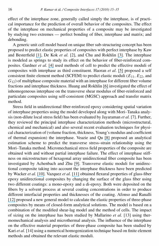
Composite Interfaces 17 (2010) 15–35 brill.nl/ci Interphase Effect on Fiber-Reinforced Polymer Composites Pramod Kumar a,∗ , Rakesh Chandra a and S. P. Singh b a Department of Mechanical Engineering, Dr B R Ambedkar National Institute of Technology, Jalandhar, India b Department of Mechanical Engineering, Indian Institute of Technology, New Delhi, India Received 1 April 2008; accepted 1 August 2008 Abstract A mathematical model has been developed for the prediction of elastic moduli of three-phase fiber- reinforced composite. This model considers composite materials consisting of three phases, namely, fiber, interphase and matrix, and incorporates the effect of fiber packing. In the present paper, the interphase is assumed to be a homogeneous and isotropic material. The elastic moduli E 11 ,E 22 ,G 12 and G 23 have been evaluated and damping coefficients η 11 ,η 22 ,η 12 and η 23 have been predicted by application of a correspon- dence principle using this developed model. The effect of interphase volume fraction on loss factors has been evaluated. Prediction of elastic moduli and loss factors has been carried out with a weak and a strong interphase. The calculated results show that the interphase volume fraction and its properties have a very sig- nificant effect on loss factor of fiber-reinforced polymer composite. Evaluation of material properties based on the finite element method is presented using representative volume element approach. Results using the developed model are in good agreement with those obtained by FEM and other methods. © Koninklijke Brill NV, Leiden, 2010 Keywords Polymer–matrix composite, interphase, complex moduli, loss factor 1. Introduction The importance of polymer composites has increased in recent years because of their low density, excellent stiffness and damping characteristics. Composites have good dissipative properties, and are hence employed to reduce the mechanical vi- bration of machine and structural systems. These materials are usually idealized with good accuracy to be viscoelastic for analytical and computational convenience. The viscoelastic damping of polymer composites arises from relaxation and recov- ery of polymer network after it has been deformed. The study of mechanical behavior of polymer composites is often restricted to a two-phase system. However, with the development of fiber coating technology, the * To whom correspondence should be addressed. E-mail: [email protected] © Koninklijke Brill NV, Leiden, 2010 DOI:10.1163/092764409X12580201111502
-
Upload
independent -
Category
Documents
-
view
0 -
download
0
Transcript of Interphase Effect on Fiber-Reinforced Polymer Composites
Composite Interfaces 17 (2010) 15–35brill.nl/ci
Interphase Effect on Fiber-Reinforced Polymer Composites
Pramod Kumar a,∗, Rakesh Chandra a and S. P. Singh b
a Department of Mechanical Engineering, Dr B R Ambedkar National Institute of Technology,Jalandhar, India
b Department of Mechanical Engineering, Indian Institute of Technology, New Delhi, India
Received 1 April 2008; accepted 1 August 2008
AbstractA mathematical model has been developed for the prediction of elastic moduli of three-phase fiber-reinforced composite. This model considers composite materials consisting of three phases, namely, fiber,interphase and matrix, and incorporates the effect of fiber packing. In the present paper, the interphase isassumed to be a homogeneous and isotropic material. The elastic moduli E11,E22,G12 and G23 have beenevaluated and damping coefficients η11, η22, η12 and η23 have been predicted by application of a correspon-dence principle using this developed model. The effect of interphase volume fraction on loss factors hasbeen evaluated. Prediction of elastic moduli and loss factors has been carried out with a weak and a stronginterphase. The calculated results show that the interphase volume fraction and its properties have a very sig-nificant effect on loss factor of fiber-reinforced polymer composite. Evaluation of material properties basedon the finite element method is presented using representative volume element approach. Results using thedeveloped model are in good agreement with those obtained by FEM and other methods.© Koninklijke Brill NV, Leiden, 2010
KeywordsPolymer–matrix composite, interphase, complex moduli, loss factor
1. Introduction
The importance of polymer composites has increased in recent years because oftheir low density, excellent stiffness and damping characteristics. Composites havegood dissipative properties, and are hence employed to reduce the mechanical vi-bration of machine and structural systems. These materials are usually idealizedwith good accuracy to be viscoelastic for analytical and computational convenience.The viscoelastic damping of polymer composites arises from relaxation and recov-ery of polymer network after it has been deformed.
The study of mechanical behavior of polymer composites is often restricted to atwo-phase system. However, with the development of fiber coating technology, the
* To whom correspondence should be addressed. E-mail: [email protected]
© Koninklijke Brill NV, Leiden, 2010 DOI:10.1163/092764409X12580201111502
16 P. Kumar et al. / Composite Interfaces 17 (2010) 15–35
effect of the interphase zone, generally called simply the interphase, is of practi-cal importance for the prediction of overall behavior of the composites. The effectof the interphase on mechanical properties of a composite may be investigatedby studying two extremes — perfect bonding of fiber, interphase and matrix; anddebonding.
A generic unit cell model based on unique fiber sub-structuring concept has beenproposed to predict elastic properties of composites with perfect interphase by Kawand Besterfield [1], De Kok et al. [2], and Chu and Rokhlin [3]. The interphaseis modeled as springs to study its effect on the behavior of fiber-reinforced com-posites. Gardner et al. [4] used methods of cell to predict the effective moduli ofcomposites with interphase as third constituent. Haoran et al. [5] proposed a selfconsistent finite element method (SCFEM) to predict elastic moduli (E11,E22, andG12) of multiphase composite material with an interphase for different fiber volumefractions and interphase thickness. Huang and Rokhlin [6] investigated the effect ofinhomogeneous interphase on the transverse shear modulus of fiber-reinforced andparticulate composites using self-consistent (MGSC) approach and transfer matrixmethod.
Stress field in unidirectional fiber-reinforced epoxy considering spatial variationof interphase properties using the model developed along with Mori–Tanaka analy-sis (non-dilute local stress field) has been evaluated by Jayaraman et al. [7]. Further,they reviewed the principal interphase characterization methods (microstructural,chemical and mechanical) and also several recent evaluation techniques for physi-cal characterization of (volume fraction, thickness, Young’s modulus and coefficientof thermal expansion) the interphase. Veazie and Qu [8] proposed an analyticalestimation scheme to predict the transverse stress–strain relationship using theMori–Tanaka method. Micromechanical stress field properties of the composite areobtained with and without partial interphase failure. The effect of interphase stiff-ness on microstructure of hexagonal array unidirectional fiber composite has beeninvestigated by Achenbach and Zhu [9]. Transverse elastic moduli for unidirec-tional composite taking into account the interphase thickness have been predictedby Wacker et al. [10]. Vazquez et al. [11] obtained flexural properties of glass-fiberepoxy unidirectional composites by changing the surface of the glass fiber usingtwo different coatings: a mono-epoxy and a di-epoxy. Both were deposited on thefibers by a solvent process at several coating concentrations in order to producedifferent interfacial properties and thicknesses of the coating. Afonso and Ranalli[12] proposed a new general model to calculate the elastic properties of three-phasecomposites by means of closed-form analytical solutions. The model is based on acombination of the modified shear-lag model and the method of cells. The impactof sizing on the interphase has been studied by Mallarino et al. [13] using ther-momechanical analysis and microthermal analysis. The influence of the interphaseon the effective material properties of three-phase composite has been studied byKari et al. [14] using a numerical homogenization technique based on finite elementmethods and obtained the relevant elastic moduli.
P. Kumar et al. / Composite Interfaces 17 (2010) 15–35 17
The effect of the interphase on damping has been discussed by Neilson [15] us-ing the rule of mixtures to determine the loss tangent (tan ϕo
c ) for ideal composites.The effect of type of interfacial bonding covering the range from weak to strong isconsidered in the works of Kubat et al. [16] and Ziegel and Ramanov [17]. Theyproposed two parameters A and B, covering together the whole range of interfacialimperfections. Parameter A and interfacial damping (tan ϕi ) characterize the inter-facial bonding in composite with poor adhesion, whereas a strong interfacial regionis defined by parameter B.
Decrease in damping with improvement in the interfacial bonding has beenobserved by Chinquin et al. [18] and it was verified by dynamic mechanical analy-sis test. A three-phase model using energy balance approach was developed byVantomme [19] to predict the longitudinal and shear loss factors for compositematerials. Finegan and Gibson [20] studied the contribution of the interphase tooverall damping in fiber-reinforced composite. Furthermore, they developed an an-alytical and FEM model [21] to evaluate the loss factor at micromechanical level.A parametric study has been carried out by Chandra et al. [22, 23] for a three-phase composite which has shown that the change in properties of fiber, matrix andinterphase leads to a change in the magnitude of effectiveness of interphase, butthe manner in which interphase would affect the various loss factors depends pre-dominately upon whether the hard or soft interphase is chosen. Chandra et al., [24]also investigated the effect of interface on damping of fiber-reinforced compositeshaving damage in the form of hairline debonding. The effect of fiber coating onlongitudinal damping capacity of fiber-reinforced metal matrix composite has beenstudied by Gu et al. [25] and predicted loss factor dependence on strain amplitude.
To the best of the authors’ knowledge, no previous analytical work has beenreported on the effect of viscoelastic interphase on the damping of composite whileincorporating the effect of fiber packing. In order to consider the effect of fiberpacking and interphase, a modified analytical three-phase model for the predictionof damping in composite is presented here. The model is based upon Huang’s [26]two-phase bridging model. Elastic moduli E11,E22,G12, and G23 are predicted inorder to compute the effect of longitudinal bridging factor α and transverse bridgingfactor β . Loss factors η11, η22, η12 and η23 are predicted by a modified three-phasebridging model and compared with the results in the existing literature. The resultsconfirm the effectiveness of the bridging model incorporating the effect of fiberpacking and actual state of stress.
2. Three Phase Bridging Model
A two-phase bridging model [26] for unidirectional fiber-reinforced composite hasbeen extended to incorporate the effect of the interphase. In the two-phase model,elastic stresses in the matrix material are correlated with the fiber by bridging ma-trix. The bridging matrix represents the load sharing capacity of one constituentphase in the composite with respect to the other phase. On the same basis stresses

18 P. Kumar et al. / Composite Interfaces 17 (2010) 15–35
in matrix, interphase and fiber are correlated by equation (1):{dσm
i
} = [AmI
ij
]{dσ I
j
},
(1){dσ I
i
} = [AIf
ij
]{dσ f
j
},
where {dσi} = {dσ11,dσ22,dσ33,dσ13,dσ12,dσ23}T is the incremental stress ten-sor; [Aij ] is the bridging matrix, and superscripts f, I and m represent the fiber,interphase and matrix, respectively. A quantity without a suffix represents the com-posite; subscripts i, j represent the contracted tensor notation.
Constituent material properties used as input for bridging model are is given inTable 1. A concentric cylinder model for unidirectional three-phase fiber-reinforcedcomposite is shown in Fig. 1 in the form of a representative volume element (RVE).It consists of fiber of radius rf bounded by an interface region of outer radius rIembedded into matrix of outer radius rm. Furthermore, the condition of perfectfiber–interphase–matrix bonding and variable state of stress is assumed within theRVE. Formulation has been done for the elastic deformation.
Let V ′ denote the volume of RVE of unidirectional fiber-reinforced compositeas shown in Fig. 1. V ′
f , V ′I , V ′
m are the volume of fiber, interphase and matrix in theRVE, respectively.
Table 1.Constituent material properties used as input for bridging model
Properties E-glass Epoxy Hard Softfiber matrix interphase interphase
E (GPa) 72.4 2.76 37.58 0.5G (GPa) 30.2 1.02 15.61 0.178Y 0.2 0.35 0.204 0.4H 0.0018 0.015 0.0084 0.0084
Figure 1. Concentric cylinder model for fiber-reinforced composite.
P. Kumar et al. / Composite Interfaces 17 (2010) 15–35 19
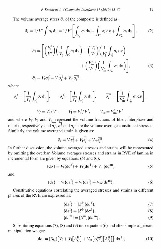
The volume average stress σ̄i of the composite is defined as:
σ̄i = 1/V ′∫
σi dν = 1/V ′[∫
V ′f
σi dν +∫
V ′i
σi dν +∫
V ′m
σi dν
]
, (2)
σ̄i =[(
V ′f
V ′
)(1
V ′f
∫
ν′f
σi dν
)+
(V ′
I
V ′
)(1
V ′I
∫
ν′i
σi dν
)
+(
V ′m
V ′
)(1
V ′m
∫
ν′m
σi dν
)]
, (3)
σ̄i = Vfσfi + VIσ
Ii + Vmσm
i ,
where
σ fi =
[1
V ′f
∫
ν′f
σi dν
], σ I
i =[
1
V ′I
∫
ν′I
σi dν
], σm
i =[
1
V ′m
∫
ν′m
σi dν
],
Vf = V ′f /V ′, VI = V ′
I /V ′, Vm = V ′m/V ′
and where Vf,VI and Vm represent the volume fractions of fiber, interphase and
matrix, respectively, and σ fi , σ I
i and σmi are the volume average constituent stresses.
Similarly, the volume averaged strain is given as:
ε̄i = Vfεfi + VIε
Ii + Vmεm
i . (4)
In further discussion, the volume averaged stresses and strains will be representedby omitting the overbar. Volume averages stresses and strains in RVE of lamina inincremental form are given by equations (5) and (6):
{dσ } = Vf{dσ f} + VI{dσ I} + Vm{dσm} (5)
and
{dε} = Vf{dεf} + VI{dεI} + Vm{dεm}. (6)
Constitutive equations correlating the averaged stresses and strains in differentphases of the RVE are expressed as:
{dεf} = [Sf]{dσ f}, (7)
{dεI} = [SI]{dσ I}, (8)
{dεm} = [Sm]{dσm}. (9)
Substituting equations (7), (8) and (9) into equation (6) and after simple algebraicmanipulation we get:
{dε} = [Sij ][Vf + VI
[AIf
ij
] + Vm[AmI
ij
][AIf
ij
]]{dσ f}, (10)
20 P. Kumar et al. / Composite Interfaces 17 (2010) 15–35
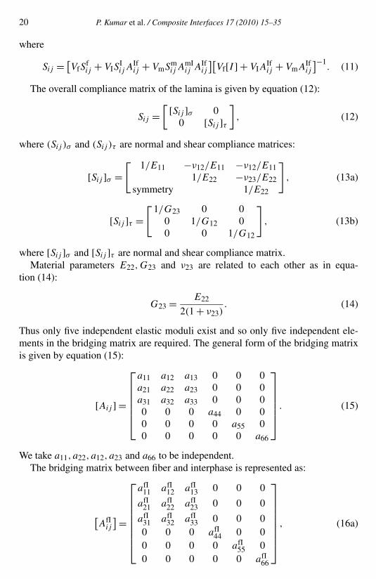
where
Sij = [VfS
fij + VIS
IijA
Ifij + VmSm
ij AmIij AIf
ij
][Vf[I ] + VIA
Ifij + VmAIf
ij
]−1. (11)
The overall compliance matrix of the lamina is given by equation (12):
Sij =[ [Sij ]σ 0
0 [Sij ]τ]
, (12)
where (Sij )σ and (Sij )τ are normal and shear compliance matrices:
[Sij ]σ =[ 1/E11 −ν12/E11 −ν12/E11
1/E22 −ν23/E22symmetry 1/E22
]
, (13a)
[Sij ]τ =[1/G23 0 0
0 1/G12 00 0 1/G12
]
, (13b)
where [Sij ]σ and [Sij ]τ are normal and shear compliance matrix.Material parameters E22,G23 and ν23 are related to each other as in equa-
tion (14):
G23 = E22
2(1 + ν23). (14)
Thus only five independent elastic moduli exist and so only five independent ele-ments in the bridging matrix are required. The general form of the bridging matrixis given by equation (15):
[Aij ] =
⎡
⎢⎢⎢⎢⎢⎣
a11 a12 a13 0 0 0a21 a22 a23 0 0 0a31 a32 a33 0 0 00 0 0 a44 0 00 0 0 0 a55 00 0 0 0 0 a66
⎤
⎥⎥⎥⎥⎥⎦
. (15)
We take a11, a22, a12, a23 and a66 to be independent.The bridging matrix between fiber and interphase is represented as:
[AfI
ij
] =
⎡
⎢⎢⎢⎢⎢⎢⎢⎣
afI11 afI
12 afI13 0 0 0
afI21 afI
22 afI23 0 0 0
afI31 afI
32 afI33 0 0 0
0 0 0 afI44 0 0
0 0 0 0 afI55 0
0 0 0 0 0 afI66
⎤
⎥⎥⎥⎥⎥⎥⎥⎦
, (16a)
P. Kumar et al. / Composite Interfaces 17 (2010) 15–35 21
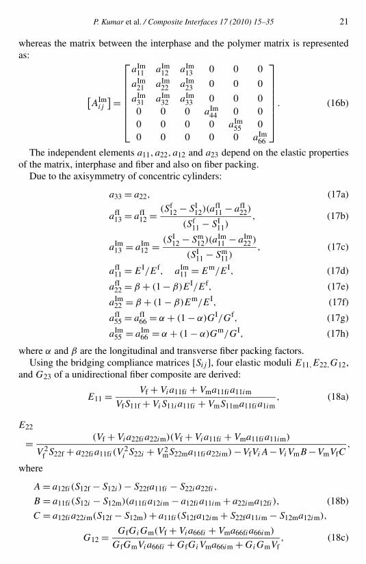
whereas the matrix between the interphase and the polymer matrix is representedas:
[AIm
ij
] =
⎡
⎢⎢⎢⎢⎢⎢⎢⎣
aIm11 aIm
12 aIm13 0 0 0
aIm21 aIm
22 aIm23 0 0 0
aIm31 aIm
32 aIm33 0 0 0
0 0 0 aIm44 0 0
0 0 0 0 aIm55 0
0 0 0 0 0 aIm66
⎤
⎥⎥⎥⎥⎥⎥⎥⎦
. (16b)
The independent elements a11, a22, a12 and a23 depend on the elastic propertiesof the matrix, interphase and fiber and also on fiber packing.
Due to the axisymmetry of concentric cylinders:
a33 = a22, (17a)
afI13 = afI
12 = (Sf12 − SI
12)(afI11 − afI
22)
(Sf11 − SI
11), (17b)
aIm13 = aIm
12 = (SI12 − Sm
12)(aIm11 − aIm
22 )
(SI11 − Sm
11), (17c)
afI11 = EI/Ef, aIm
11 = Em/EI, (17d)
afI22 = β + (1 − β)EI/Ef, (17e)
aIm22 = β + (1 − β)Em/EI, (17f)
afI55 = afI
66 = α + (1 − α)GI/Gf, (17g)
aIm55 = aIm
66 = α + (1 − α)Gm/GI, (17h)
where α and β are the longitudinal and transverse fiber packing factors.Using the bridging compliance matrices [Sij ], four elastic moduli E11,E22,G12,
and G23 of a unidirectional fiber composite are derived:
E11 = Vf + Via11fi + Vma11fia11im
VfS11f + ViS11ia11fi + VmS11ma11fia1im, (18a)
E22
= (Vf + Via22fia22im)(Vf + Via11fi + Vma11fia11im)
V 2f S22f + a22fia11fi (V
2i S22i + V 2
mS22ma11fia22im) −VfViA−ViVmB −VmVfC,
where
A = a12fi (S12f − S12i ) − S22fa11fi − S22ia22fi ,
B = a11fi (S12i − S12m)(a11fia12im − a12fia11im + a22ima12fi ), (18b)
C = a12fia22im(S12f − S12m) + a11fi (S12fa12im + S22fa11im − S12ma12im),
G12 = GfGiGm(Vf + Via66fi + Vma66fia66im)
GfGmVia66fi + GfGiVma66im + GiGmVf, (18c)
22 P. Kumar et al. / Composite Interfaces 17 (2010) 15–35
G23 = Vf + Via44fi + Vma44fia44im
VfS44f + ViS44ia44fi + V4S44ma44fia44im. (18d)
Further, using the correspondence principle in which Ef,EI,Em become com-plex with the loss modulus associated represented by the imaginary part, the com-pliance matrix would also be complex. As a result, composite moduli in complexform are obtained as given in equation (19) which representing the storage moduli(E′
ij ) and loss moduli (E′′ij ) components as real and imaginary parts, respectively,
using these loss factors η11, η22, η12 and η23 are predicted:
Eij = E′ij + jE′′
ij , ηij = E′′ij
E′ij
. (19)
3. Finite Elements Model
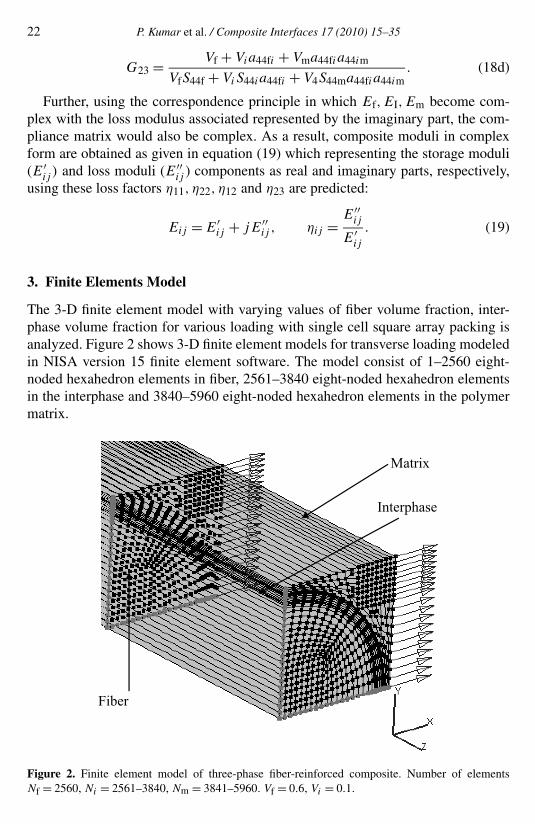
The 3-D finite element model with varying values of fiber volume fraction, inter-phase volume fraction for various loading with single cell square array packing isanalyzed. Figure 2 shows 3-D finite element models for transverse loading modeledin NISA version 15 finite element software. The model consist of 1–2560 eight-noded hexahedron elements in fiber, 2561–3840 eight-noded hexahedron elementsin the interphase and 3840–5960 eight-noded hexahedron elements in the polymermatrix.
Figure 2. Finite element model of three-phase fiber-reinforced composite. Number of elementsNf = 2560, Ni = 2561–3840, Nm = 3841–5960. Vf = 0.6, Vi = 0.1.
P. Kumar et al. / Composite Interfaces 17 (2010) 15–35 23
By applying the strain energy concept, the unit cell [21] is analyzed to evaluatethe damping capacity of the composite from those of its constituents.
The loss factor is expressed as:
η =∑n
i=1 ηiWi∑ni=1 Wi
. (20)
The loss factor for the three-phase model considering the effect of the interphaseis expressed as:
η = ηfWf + ηIWI + ηmWm
Wf + WI + Wm. (21)
The strain energy stored in the composite under loading is written as:
Wc = 1
2
∫
V
σij εij dV = 1
2
∫
V
σTij Sij σij dV. (22)
The strain energy stored in fiber, interphase and matrix in a unit cell is written as:
Wf = 1
2
∑{σT
ij
}f{Sij }f{σij }f dVf,
WI = 1
2
∑{σT
ij
}I{Sij }I{σij }I dVI , (23)
Wm = 1
2
∑{σT
ij
}m{Sij }m{σij }m dVm.
Equating expression Wc as the sum of the strain energy stored in the componentswe can evaluate the overall elastic moduli. These results for moduli and loss factorsare compared with output of the bridging model for three-phase composites anddiscussed in detail for various parameters of the composites.
4. Results and Discussion
Elastic moduli and loss factors are predicted using a three-phase bridging modeldeveloped for various values of the fiber volume fraction. The effect of fiber packingfactors is also evaluated on the elastic moduli and loss factors.
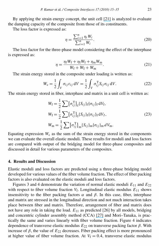
Figures 3 and 4 demonstrate the variation of normal elastic moduli E11 and E22with respect to fiber volume fraction Vf. Longitudinal elastic modulus E11 showsinsensitivity to the fiber packing factors α and β . In this case, fiber, interphaseand matrix are stressed in the longitudinal direction and not much interaction takesplace between fiber and matrix. Therefore, arrangement of fiber and matrix doesnot have any role in taking the load. E11 as predicted [26] by all models, bridgingand concentric cylinder assembly method (CCA) [27] and Mori–Tanaka, is prac-tically the same and varies linearly with fiber volume fraction. Figure 4 indicatesdependence of transverse elastic modulus E22 on transverse packing factor β . Withincrease of β , the value of E22 decreases. Fiber packing effect is more pronouncedat higher value of fiber volume fraction. At Vf = 0.4, transverse elastic modulus
24 P. Kumar et al. / Composite Interfaces 17 (2010) 15–35
E22 decreases by 36% and at Vf = 0.6,E22 decrease by 42% for β increase from0.5 to 1.0. Figure 4 also shows the comparison with the CCA method. For β = 1,bridging model results match with those obtained with the CCA method. FEM re-
Figure 3. Variation of elastic modulus, E11 with respect to fiber volume fraction.
Figure 4. Variation of elastic modulus, E22 with respect to fiber volume fraction.
P. Kumar et al. / Composite Interfaces 17 (2010) 15–35 25
sults are in good agreement with bridging model results for lower values of fibervolume fractions.
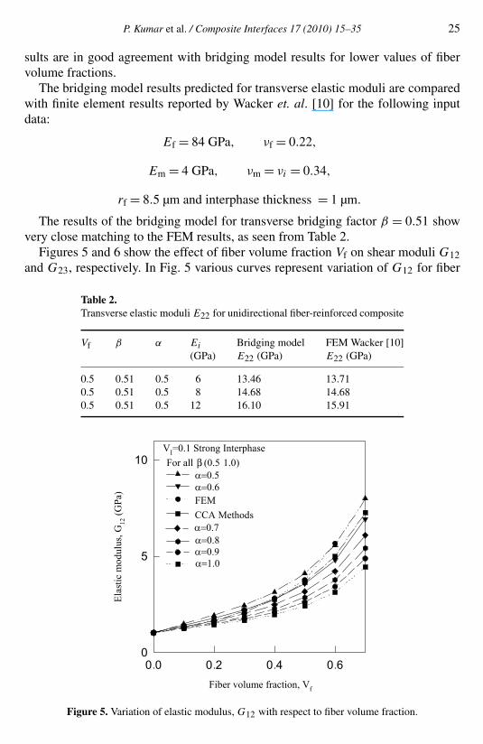
The bridging model results predicted for transverse elastic moduli are comparedwith finite element results reported by Wacker et. al. [10] for the following inputdata:
Ef = 84 GPa, νf = 0.22,
Em = 4 GPa, νm = νi = 0.34,
rf = 8.5 µm and interphase thickness = 1 µm.
The results of the bridging model for transverse bridging factor β = 0.51 showvery close matching to the FEM results, as seen from Table 2.
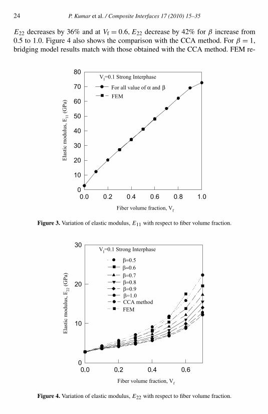
Figures 5 and 6 show the effect of fiber volume fraction Vf on shear moduli G12and G23, respectively. In Fig. 5 various curves represent variation of G12 for fiber
Table 2.Transverse elastic moduli E22 for unidirectional fiber-reinforced composite
Vf β α Ei Bridging model FEM Wacker [10](GPa) E22 (GPa) E22 (GPa)
0.5 0.51 0.5 6 13.46 13.710.5 0.51 0.5 8 14.68 14.680.5 0.51 0.5 12 16.10 15.91
Figure 5. Variation of elastic modulus, G12 with respect to fiber volume fraction.

26 P. Kumar et al. / Composite Interfaces 17 (2010) 15–35
Figure 6. Variation of elastic modulus, G23 with respect to fiber volume fraction.
packing factor 0.5 < α < 1.0. With the increase in the value of α,G12 decreasesrapidly for lower range of α. Increase in longitudinal shear modulus is more forlower values of α when fiber volume fraction is large. The results for G12 indicatethat the transverse packing factor β has no effect on its prediction. Loss in longi-tudinal shear modulus with increase in α is regular, i.e. similar curves are obtainedfor all value of α. FEM results are closer to bridging model results for α = 0.6 forlower value of fiber volume fraction. Figure 6 shows a similar trend as for G12 butwith different magnitudes, in relation to different values of transverse packing fac-tor β . FEM results have similar trend with less magnitude. As is evident here, themagnitude of G23 is independent of longitudinal packing factor α.
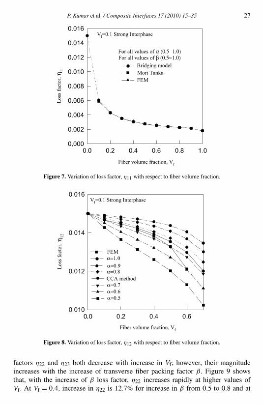
Figures 7 and 8 illustrate the effect of Vf on longitudinal normal loss factor (η11)and longitudinal shear loss factor (η12) respectively. In Fig. 7, η11 decreases withthe increase of fiber volume fraction. Decrease in magnitude of loss factors is quiterapid for lower values of Vf and it shows insensitivity towards the fiber packing fac-tors α and β . The prediction for η11 by FEM with single cell square array packingshows very good agreement with bridging model results. Figure 8 shows that forfiber packing factor α = 0.7, the loss factor η12 is very near to the results obtainedby CCA methods. Longitudinal shear loss factor as obtained by the bridging modelcompare very well with the CCA method for all values of Vf. FEM results of lossfactor η12 are comparable with bridging results for longitudinal fiber packing factorat α = 0.7 indicating its effectiveness to account for a variable state of stress in thecomposites.
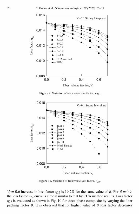
Figures 9 and 10 demonstrate the variation of transverse normal loss factor η22and transverse shear loss factor η23 with respect to fiber volume fraction Vf. Loss
P. Kumar et al. / Composite Interfaces 17 (2010) 15–35 27
Figure 7. Variation of loss factor, η11 with respect to fiber volume fraction.
Figure 8. Variation of loss factor, η12 with respect to fiber volume fraction.
factors η22 and η23 both decrease with increase in Vf; however, their magnitudeincreases with the increase of transverse fiber packing factor β . Figure 9 showsthat, with the increase of β loss factor, η22 increases rapidly at higher values ofVf. At Vf = 0.4, increase in η22 is 12.7% for increase in β from 0.5 to 0.8 and at
28 P. Kumar et al. / Composite Interfaces 17 (2010) 15–35
Figure 9. Variation of transverse loss factor, η22.
Figure 10. Variation of transverse loss factor, η23.
Vf = 0.6 increase in loss factor η22 is 19.2% for the same value of β . For β = 0.9,the loss factor η22 curve is almost similar to that by CCA method results. Loss factorη23 is evaluated as shown in Fig. 10 for three-phase composite by varying the fiberpacking factor β . It is observed that for higher value of β loss factor decreases

P. Kumar et al. / Composite Interfaces 17 (2010) 15–35 29
Figure 11. Effect of interphase volume fraction on η11 (strong interphase).
slowly as compared to lower value of β . As Vf increases from 0.4 to 0.6, loss factorη23 decreases by 10.4% for β = 0.5, and 3.6% for β = 1.0. The prediction for η23by FEM with single cell square array packing shows lower results.
Loss factors η11 and η12 of fiber-reinforced composite evaluated by varying thestrong interphase thickness from 0.02 to 0.1 are shown in Figs 11 and 12. Figure 11shows that η11 increases with the increase in interphase volume fraction. Moreoverη11 is independent of fiber packing factor α and β . Loss factor η12 in Fig. 12 illus-trates its dependence on α which increases with increase of α regularly; however,it decreases marginally with increase in Vi . Loss factor η12 for composite predictedusing FEM and bridging model are compared in Fig. 12. Results from FEM andbridging model for β = 0.9 show good agreement with each other.
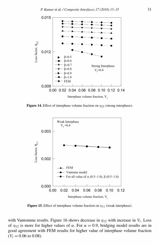
Figures 13 and 14 demonstrate the variation of transverse normal loss factor η22and transverse shear loss factor η23 with respect to change in strong interphase vol-ume fraction respectively. Different curves represent behavior of η22 and η23 fordifferent value of β . Loss factor η22 is compared with FEM and Vantomme [19] re-sults in Fig. 13. Results from the bridging model are comparable to FEM results forsingle cell model. For β = 1.0, bridging model results match well with Vantommemodel results where the effect of fiber packing is not considered. The Vantommemodel is based upon law of mixture, considering the uniform state of stress in fiber,interphase and matrix. This indicates that β = 1 refers to the model with singlefiber, which does not consider the effect of fiber packing. Square fiber packing hasbeen considered in FEM model for the prediction of η22. In the present model, theeffect of fiber packing is obtained by variation of β . Figure 14 illustrates the varia-tion of η23 with strong interphase. With increase in β , loss factor η23 increases, butthe increase in η23 is not much for higher values of β .

30 P. Kumar et al. / Composite Interfaces 17 (2010) 15–35
Figure 12. Effect of interphase volume fraction on η12 (strong interphase).
Figure 13. Effect of interphase volume fraction on η22 (strong interphase).
Variation of η11 and η12 with respect to interphase volume fraction Vi is pre-sented in Figs 15 and 16 considering a weak interphase. Loss factor η11 decreasesmarginally with increase in Vi . Fiber packing factor α and β has no effect on η11.Figure 15 also shows comparison with FEM [23] results. Both results have the sametrend with almost same magnitude. Bridging model results are in good agreement
P. Kumar et al. / Composite Interfaces 17 (2010) 15–35 31
Figure 14. Effect of interphase volume fraction on η23 (strong interphase).
Figure 15. Effect of interphase volume fraction on η11 (weak interphase).
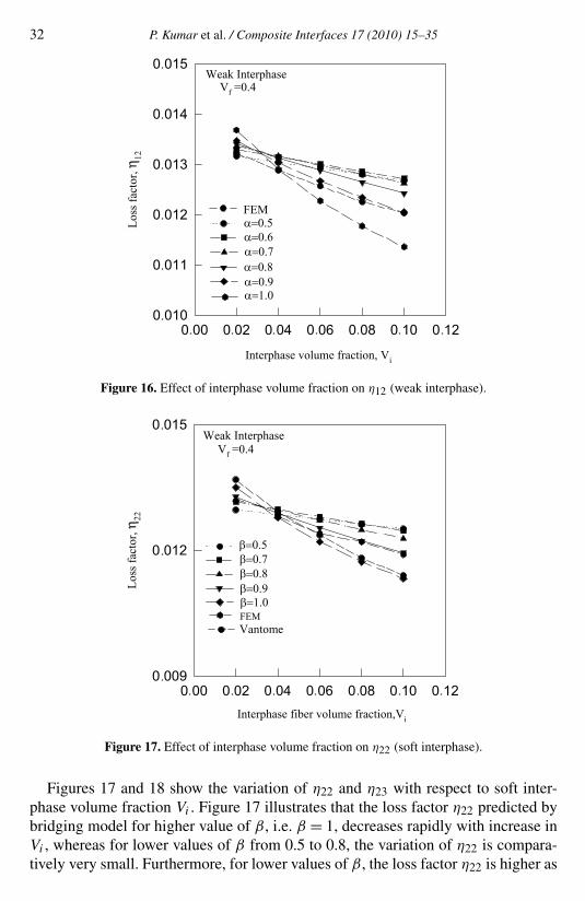
with Vantomme results. Figure 16 shows decrease in η12 with increase in Vi . Lossof η12 is more for higher values of α. For α = 0.9, bridging model results are ingood agreement with FEM results for higher value of interphase volume fraction(Vi = 0.06 to 0.08).
32 P. Kumar et al. / Composite Interfaces 17 (2010) 15–35
Figure 16. Effect of interphase volume fraction on η12 (weak interphase).
Figure 17. Effect of interphase volume fraction on η22 (soft interphase).
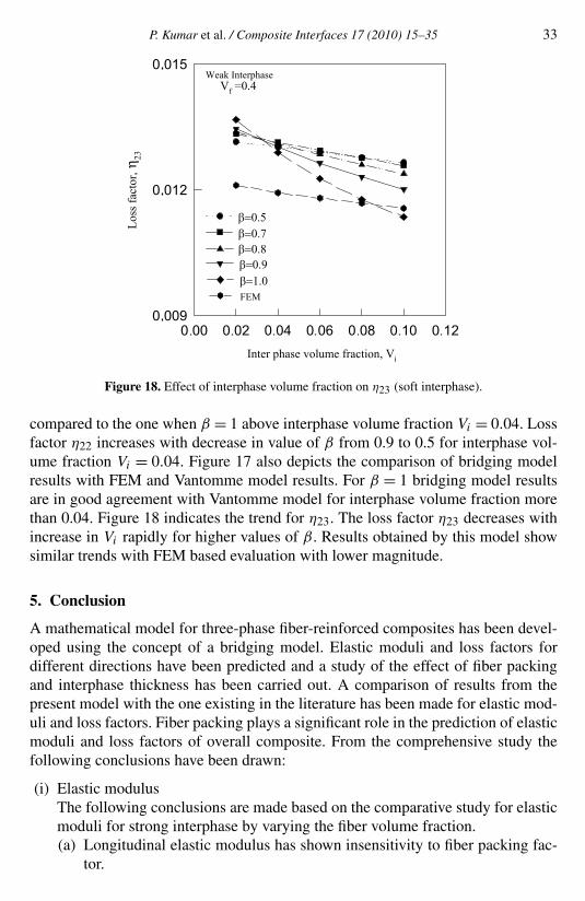
Figures 17 and 18 show the variation of η22 and η23 with respect to soft inter-phase volume fraction Vi . Figure 17 illustrates that the loss factor η22 predicted bybridging model for higher value of β , i.e. β = 1, decreases rapidly with increase inVi , whereas for lower values of β from 0.5 to 0.8, the variation of η22 is compara-tively very small. Furthermore, for lower values of β , the loss factor η22 is higher as
P. Kumar et al. / Composite Interfaces 17 (2010) 15–35 33
Figure 18. Effect of interphase volume fraction on η23 (soft interphase).
compared to the one when β = 1 above interphase volume fraction Vi = 0.04. Lossfactor η22 increases with decrease in value of β from 0.9 to 0.5 for interphase vol-ume fraction Vi = 0.04. Figure 17 also depicts the comparison of bridging modelresults with FEM and Vantomme model results. For β = 1 bridging model resultsare in good agreement with Vantomme model for interphase volume fraction morethan 0.04. Figure 18 indicates the trend for η23. The loss factor η23 decreases withincrease in Vi rapidly for higher values of β . Results obtained by this model showsimilar trends with FEM based evaluation with lower magnitude.
5. Conclusion
A mathematical model for three-phase fiber-reinforced composites has been devel-oped using the concept of a bridging model. Elastic moduli and loss factors fordifferent directions have been predicted and a study of the effect of fiber packingand interphase thickness has been carried out. A comparison of results from thepresent model with the one existing in the literature has been made for elastic mod-uli and loss factors. Fiber packing plays a significant role in the prediction of elasticmoduli and loss factors of overall composite. From the comprehensive study thefollowing conclusions have been drawn:
(i) Elastic modulusThe following conclusions are made based on the comparative study for elasticmoduli for strong interphase by varying the fiber volume fraction.(a) Longitudinal elastic modulus has shown insensitivity to fiber packing fac-
tor.
34 P. Kumar et al. / Composite Interfaces 17 (2010) 15–35
(b) Transverse normal, transverse shear and longitudinal shear elastic modulidecrease with the increase in fiber packing factor. For transverse packingfactor equal to 1, results of transverse normal modulus and transverse shearmodulus are same as CCA results. For β = 0.5 transverse normal modulusresults are very near to FEM based results reported in literature. Furtherstudies are being carried out to correlate the value of β for different typesof fiber packing geometries.
(ii) Loss factorsThe following conclusions are made based on the comparative study for lossfactors.(a) Longitudinal normal loss factor has no effect of fiber packing factor.
(b) Loss factors increase with increase of longitudinal fiber packing factor andtransverse packing factor.
(c) Longitudinal normal loss factor increases for strong interphase with theincrease in interphase volume fraction.
(d) Transverse normal loss factor, longitudinal normal and longitudinal shearloss factor decrease marginally with increase of strong interphase volumefraction. For β = 1 transverse normal loss factor results correlate well withresults reported by Vantomme.
(e) For weak interphase, loss factors decrease with the increase of interphasevolume fraction. Reductions in loss factors are significant for various val-ues of fiber packing factors.
References
1. A. K. Kaw and G. H. Besterfield, Effect of interphase on mechanical behavior of composites,J. Engng Mech. 117, 2641–2658 (1991).
2. J. M. M. De Kok, E. J. van Kilinken and A. A. J. N. Peijs, Influence of fiber surface treatmenton transverse properties of carbon fiber-reinforced composites, in: Proc. Intl Conf. Adv. Com-pos. Mater., Minerals, Metals and Materials Society (TMS), pp. 427–432. Warrendale, PA, USA(1993).
3. Y. C. Chu and S. I. Rokhlin, Determination of fiber–matrix interphase moduli from experimentalmoduli of composites with multilayered fibers, Mech. Mater. 21, 191–215 (1995).
4. S. D. Gardner, C. U. Pittman Jr., T. C. Chang, B. Y. Low and R. M. Hackett, Microstress distribu-tion in graphite fiber/epoxy composite containing an elastomeric interphase: response to uniaxialand biaxial loading conditions, Composites 26, 269–280 (1995).
5. C. Haoran, S. X. Feng and F. M. Williams, Effect of interphase on overall average mechanicalproperties and local stress field of multiphase medium materials, Computat. Mater. Sci. 4, 117–124 (1995).
6. W. Huang and S. I. Rokhlin, Generalized self-consistent model for composites with functionallygraded and multilayered interphase transfer matrix approach, Mech. Mater. 22, 219–247 (1996).
7. K. Jayaraman, Z. Gao and K. L. Reifsnider, Interphase in unidirectional fiber-reinforced epoxies:effect on local stress field, J. Compos. Technol. Res. 16, 21–31 (1992).
P. Kumar et al. / Composite Interfaces 17 (2010) 15–35 35
8. D. R. Veazie and J. Qu, Effect of interphase on transverse stress–strain behavior in unidirectionalfiber-reinforced metal matrix composites, Compos. Engng 5, 597–610 (1995).
9. J. D. Achenbach and H. Zhu, Effect of interphases on micro and macromechanical behaviour ofhexagonal-array fiber composites, in: Proc. Winter Ann. Mtg Conf, ASME Publication 18 (1990).
10. G. Wacker, A. K. Bledzki and A. Chate, Effect of interphase on the transverse young’s modulusof glass/epoxy composites, Composites Part A 29A, 619–626 (1998).
11. A. Vazquez, M. Ambrustolo, S. M. Moschiar, M. M. Reboredo and J. F. Gérard, Interphase modifi-cation in unidirectional glass-fiber epoxy composites, Compos. Sci. Technol. 58, 549–558 (1998).
12. J. C. Afonso and G. Ranalli, Elastic properties of three-phase composites: analytical model basedon the modified shear-lag model and the method of cells, Compos. Sci. Technol. 65, 1264–1275(2005).
13. S. Mallarino, J. F. Chailan and J. L. Vernet, Interphase study in cyanate/glass fibre compositesusing thermomechanical analysis and micro-thermal analysis, Compos. Sci. Technol. 69, 28–32(2009).
14. S. Kari, H. Berger, U. Gabbert, R. Guinovart-Dıaz, J. Bravo-Castillero and R. R. Ramos, Evalua-tion of influence of interphase material parameters on effective material properties of three phasecomposites, Compos. Sci. Technol. 68, 684–691 (2008).
15. L. E. Nielson, Mechanical Properties of Polymer and Composites, Vol. 2. Dekker, New York, USA(1974).
16. J. Kubat, M. Rigdahl and M. Welander, Characterization of interfacial interactions in high densitypolyethylene filled with glass spheres using dynamic-mechanical analysis, J. Appl. Polym. Sci. 39,1527–1539 (1990).
17. K. D. Ziegel and A. Ramanov, Modulus reinforcement in elastomer composites inorganic fillers,J. Appl. Polym. Sci. 17, 1119–1131 (1973).
18. J. Chinquin, B. Chabert, J. Chauchard, E. Morel and J. P. Totignon, Characterization of thermo-plastic (polyamide) reinforced with unidirectional glass fibers, matrix additives and fibers surfacetreatment influence on mechanical and viscoelastic properties, Composites 21, 141–147 (1990).
19. J. Vantomme, A parametric study of material damping in fiber-reinforced plastics, Composites 26,147–153 (1995).
20. I. C. Finegan and R. F. Gibson, Improvement of damping at micromechanical level in polymercomposite materials under transverse loading by the use of special fiber coatings, J. Vibr. Acoust.120, 623–627 (1998).
21. I. C. Finegan and R. F. Gibson, Analytical modeling of damping at micromechanical level inpolymer composites reinforced with coated fibers, Compos. Sci. Technol. 60, 1077–1084 (2000).
22. R. Chandra, S. P Singh and K. Gupta, Micromechanical damping models for fiber-reinforcedcomposites: a comparative study, Composites: Part A 33, 789–796 (2002).
23. R. Chandra, S. P. Singh and K. Gupta, A study of damping in fiber-reinforced composite, J. SoundVibr. 262, 475–496 (2003).
24. R. Chandra, S. P. Singh and K. Gupta, Prediction of damping in three-phase fiber-reinforced com-posites, Defence Sci. J. 3, 325–337 (2003).
25. J. Gu, X. Zhang and Gu Mngyuan, Effect of fiber coating on longitudinal damping capacity offiber-reinforced metal matrix composite, Mater. Lett. 59, 180–184 (2005).
26. Z. M. Haung, Simulation of mechanical properties of fibrous composite by bridging microme-chanical model, Composites: Part A 32, 143–172 (2001).
27. Y. Benveniste, G. J. Dvorak and T. Chen, Stress field in composites with coated inclusions, Mech.Mater. 7, 305–317 (1989).