
International Journal of Numerical Methods for Heat & Fluid Flow Article information: For Authors
25
International Journal of Numerical Methods for Heat & Fluid Flow Numerical simulation of flow through an eccentric annulus with heat transfer Amit K. Chauhan B.V.S.S.S. Prasad B.S.V. Patnaik Article information: To cite this document: Amit K. Chauhan B.V.S.S.S. Prasad B.S.V. Patnaik , (2014),"Numerical simulation of flow through an eccentric annulus with heat transfer", International Journal of Numerical Methods for Heat & Fluid Flow, Vol. 24 Iss 8 pp. 1864 - 1887 Permanent link to this document: http://dx.doi.org/10.1108/HFF-07-2013-0230 Downloaded on: 17 November 2014, At: 22:36 (PT) References: this document contains references to 29 other documents. To copy this document: [email protected] The fulltext of this document has been downloaded 20 times since 2014* Access to this document was granted through an Emerald subscription provided by Token:JournalAuthor:A591C24F-25EA-488D-8048-2E47E2F540FE: For Authors If you would like to write for this, or any other Emerald publication, then please use our Emerald for Authors service information about how to choose which publication to write for and submission guidelines are available for all. Please visit www.emeraldinsight.com/authors for more information. About Emerald www.emeraldinsight.com Emerald is a global publisher linking research and practice to the benefit of society. The company manages a portfolio of more than 290 journals and over 2,350 books and book series volumes, as well as providing an extensive range of online products and additional customer resources and services. Emerald is both COUNTER 4 and TRANSFER compliant. The organization is a partner of the Committee on Publication Ethics (COPE) and also works with Portico and the LOCKSS initiative for digital archive preservation. *Related content and download information correct at time of download. Downloaded by Mr Amit Kumar Chauhan At 22:36 17 November 2014 (PT)
Transcript of International Journal of Numerical Methods for Heat & Fluid Flow Article information: For Authors

International Journal of Numerical Methods for Heat & Fluid FlowNumerical simulation of flow through an eccentric annulus with heat transferAmit K. Chauhan B.V.S.S.S. Prasad B.S.V. Patnaik
Article information:To cite this document:Amit K. Chauhan B.V.S.S.S. Prasad B.S.V. Patnaik , (2014),"Numerical simulation of flow through aneccentric annulus with heat transfer", International Journal of Numerical Methods for Heat & Fluid Flow, Vol.24 Iss 8 pp. 1864 - 1887Permanent link to this document:http://dx.doi.org/10.1108/HFF-07-2013-0230
Downloaded on: 17 November 2014, At: 22:36 (PT)References: this document contains references to 29 other documents.To copy this document: [email protected] fulltext of this document has been downloaded 20 times since 2014*Access to this document was granted through an Emerald subscription provided byToken:JournalAuthor:A591C24F-25EA-488D-8048-2E47E2F540FE:
For AuthorsIf you would like to write for this, or any other Emerald publication, then please use our Emerald forAuthors service information about how to choose which publication to write for and submission guidelinesare available for all. Please visit www.emeraldinsight.com/authors for more information.
About Emerald www.emeraldinsight.comEmerald is a global publisher linking research and practice to the benefit of society. The companymanages a portfolio of more than 290 journals and over 2,350 books and book series volumes, as well asproviding an extensive range of online products and additional customer resources and services.
Emerald is both COUNTER 4 and TRANSFER compliant. The organization is a partner of the Committeeon Publication Ethics (COPE) and also works with Portico and the LOCKSS initiative for digital archivepreservation.
*Related content and download information correct at time of download.Dow
nloa
ded
by M
r A
mit
Kum
ar C
hauh
an A
t 22:
36 1
7 N
ovem
ber
2014
(PT
)

Numerical simulation of flowthrough an eccentric annulus
with heat transferAmit K. Chauhan
Department of Applied Mechanics, Indian Institute of Technology Madras,Chennai, India
B.V.S.S.S. PrasadDepartment of Mechanical Engineering, Indian Institute of Technology Madras,
Chennai, India, and
B.S.V. PatnaikDepartment of Applied Mechanics, Indian Institute of Technology Madras,
Chennai, India
Abstract
Purpose – The purpose of this paper is to investigate the effect of narrow gap on the fluid flow andheat transfer through an eccentric annular region is numerically. Flow through an eccentric annulargeometry is a model problem of practical interest.Design/methodology/approach – The approach involves standard finite volume-based SIMPLEscheme. The numerical simulations cover the practically relevant Reynolds number range of 104-106.Findings – In the narrow gap region, temperature shoot up was observed due to flow maldistributionwith an attendant reduction in the heat removal from the wall surfaces. CFD analysis is presented with theaid of, streamlines, isotherms, axial velocity contours, etc. The engineering parameters of interest such as,Nusselt number, wall shear stress, etc., is presented to study the effect of eccentricity and radius ratio.Research limitations/implications – The present investigation is a simplified model for the rodbundle heat transfer studies. However, the detailed study of sectorial mass flux distribution is a usefulprecursor to the thermal hydraulics of rod bundles.Practical implications – For nuclear reactor fuel rods, the effect of eccentricity is going to be detrimentaland might lead to the condition of critical heat flux. A thorough sub-channel analysis is very useful.Social implications – Nuclear safety standards require answers to a wide a range of what-if typehypothetical scenarios to enable preparedness. This study is a highly simplified model and a first stepin that direction.Originality/value – The narrow gap region has been systematically investigated for the first time.A detailed sectorial analysis reveals that, flow maldistribution and the attendant temperature shoot upin the narrow gap region is detrimental to the safe operation.
Keywords CFD, Annular flows, Eccentricity, Nuclear engineering, Rod bundles, Thermal hydraulics
Paper type Research paper
The current issue and full text archive of this journal is available atwww.emeraldinsight.com/0961-5539.htm
Received 26 August 2013Revised 6 March 2014Accepted 15 April 2014
International Journal of NumericalMethods for Heat & Fluid FlowVol. 24 No. 8, 2014pp. 1864-1887r Emerald Group Publishing Limited0961-5539DOI 10.1108/HFF-07-2013-0230
NomenclatureCf skin friction coefficient,
ðtoÞ=ð12 rU 2ÞDh hydraulic diameter of annulus,
D2�D1, m
E energy, J/kge eccentricity, s/r2�r1
f Darcy friction factor, 2DpDh/LrU2
G0 mass flux for e¼ 0.0, kg/m2s
The authors thank the annonymous referees for their valuable comments. The authors aregrateful to Board of Research in Nuclear Science (BRNS), India for supporting one of the authorsAmit K. Chauhan (AKC) through a Fellowship.
1864
HFF24,8
Dow
nloa
ded
by M
r A
mit
Kum
ar C
hauh
an A
t 22:
36 1
7 N
ovem
ber
2014
(PT
)

1. IntroductionIn a large number of practical applications such as shell and tube heat exchangers,nuclear reactors, drilling equipment, etc., a cylindrical annular geometry forms thebasic model for analyzing the thermal and hydrodynamic characteristics of designinterest. In most of these applications, the flow in the vicinity of the inner tube can bemodeled as an annular flow. For flow through annular passages, the radius ratio (a) isdefined as inner radius (r1) to outer radius (r2). The value of a close to unity representsthe annuli with narrow gap. In the context of fuel bundles, the entire pin-bundlewill be seated on spacer pads. If this is modeled as a single inner tube, it provides amajor source of eccentricity. Furthermore, due to prolonged exposure to hightemperatures, there is a possibility of creep distortions. This can easily result in flowmaldistribution, as the attendant hydrodynamic and heat transfer characteristics aremodified. When liquids are employed as coolants, such eccentricities might even leadto undesirable phase change. It may be emphasized that, while the narrow gap may becreated by increasing either radius ratio (a) or eccentricity (e), their effect may notbe the same.
In the literature, a variety of fluid-thermal aspects have been studied either byexpermental or numerical means (Lee and Barrow, 1963; Barrow et al., 1965; Jonssonand Sparrow, 1966; Trombetta, 1971; Patel and Ingham, 1983; Ogino et al., 1987; Nouriet al., 1993; Batra and Eissa, 1994; Velusamy and Garg, 1994; Manglik and Fang, 1995;Torii and Yang, 1997; Fang et al., 1999; Yoo, 2005; Kaneda et al., 2003; Hosseini et al.,2005; Ninokata et al., 2005; Lu and Wang, 2008; El-Shaarawi et al., 2007; Nikitin et al.,2009; Sreenivasulu and Prasad, 2009; Kelessidis et al., 2011; Piot and Tavoularis, 2011).To enable a cogent view of the available literature, the details are presented in the formof a Table I. It can be observed that, a number of investigators have worked on theannular geometry, over a range of radius ratios and eccentricities. However, for largeradius ratios (close to unity) and varying eccentricities of practical interest, there arehardly any studies in this parametric space. The presence of geometric distortions in
G mass flux, kg/m2
g gap between two cylinders,r2�r1�s, m
k turbulent kinetic energy, m2/s2
Nu Nusselt number, hL/kNus Sectorial Nusselt numberq00 heat flux, W/m2
q000 heat flux, q000¼ 500 W/m2
Q Volumetric flow rate, m3s�1
r1,r2 inner and outer radii, mRe Reynolds number, rUbDh/mS1,S2 generation and source term in
turbulences distance between the two
cylinders, mT temperature, KTin inlet temperature, KUb area averaged velocity, m/sUm maximum velocity, m/s
V velocity vector (uiþ uj), m/sui,uj x and y component of velocity, m/su0,u0 x and y component of velocity
fluctuationx dimensionless distance between
gap (outer to inner cylinder)Y dissipation term in turbulenceyþ viscous grid spacing
Greek symbolsa radius ratio, r1/r2
y Angle along the circumference ofinner cylinder
F dimensionless temperature,(T�Tin)/Tin
v kinematic viscosity, m2s�1
r density, kg m�3
t wall shear stress, N/m2
1865
Numericalsimulation of
flow through aneccentric annulus
Dow
nloa
ded
by M
r A
mit
Kum
ar C
hauh
an A
t 22:
36 1
7 N
ovem
ber
2014
(PT
)

Au
thor
sR
adiu
sra
tio
(a)
Ecc
entr
icit
y(e
)R
eyn
old
sn
um
ber
(Re)
Th
erm
alb
oun
dar
yco
nd
itio
nR
emar
k
Lee
and
Bar
row
(196
3),
Bar
row
etal.
(196
5)0.
25,
0.38
,0.
60-
110
4-5�
104
Con
stan
th
eat
flu
xat
inn
ercy
lin
der
Ex
per
imen
tal
Jon
sson
and
Sp
arro
w(1
966)
0.28
,0.
56,
0.75
0-1
1.8�
104-1
.8�
105
–E
xp
erim
enta
l
Tro
mb
etta
(197
1)0.
005-
0.2
0.8,
1–
Con
stan
th
eat
flu
x,
con
stan
tte
mp
erat
ure
atin
ner
cyli
nd
erN
um
eric
al
Pat
elan
dIn
gh
am(1
983)
0-0.
5C
onst
ant
tem
per
atu
reon
inn
eran
dou
ter
wal
lN
um
eric
al
Og
ino
etal.
(198
7)0.
3,0.
5,0.
60.
25-0
.75
5�
103-4�
104
Con
stan
tte
mp
erat
ure
atin
ner
and
oute
rcy
lin
der
Ex
per
imen
tal
Nou
riet
al.
(199
3)0.
50.
0,0.
5,1.
08.
9�
103,
2.66�
104
–E
xp
erim
enta
lB
atra
and
Eis
sa(1
994)
0.2-
0.7
0.0-
1.0
–C
onst
ant
hea
tfl
ux
onei
ther
wal
lN
um
eric
alV
elu
sam
yan
dG
arg
(199
4)0.
1-0.
80.
2-0.
9–
–N
um
eric
al
Man
gli
kan
dF
ang
(199
5)0.
25-0
.75
0.0-
0.6
–C
onst
ant
hea
tfl
ux
and
tem
per
atu
reat
inn
ercy
lin
der
Nu
mer
ical
Tor
iian
dY
ang
(199
7)0.
2,0.
5an
d0.
80.
0-0.
810
4-1
05–
Nu
mer
ical
Fan
get
al.
(199
9)0.
2-0.
80.
2-0.
8–
–N
um
eric
alY
oo(2
005)
0.2
0–
Con
stan
th
eat
flu
xon
inn
erw
all
Nu
mer
ical
Kan
eda
etal.
(200
3)0.
001-
0.99
0.0
103-1
06–
Nu
mer
ical
Hos
sein
iet
al.
(200
5)0.
240.
21,
0.5,
0.7
and
1–
Con
stan
th
eat
flu
xon
the
oute
rw
all
Ex
per
imen
tal
Nin
okat
aet
al.
(200
5)0.
1an
d0.
50.
58.
4�
103,
1.21�
104
–N
um
eric
alL
uan
dW
ang
(200
8)0.
80.
010
-3�
104
–E
xp
erim
enta
lE
l-S
haa
raw
iet
al.
(200
7)0.
1-0.
70.
1-0.
7–
Con
stan
tte
mp
erat
ure
onin
ner
wal
lN
um
eric
al
Nik
itin
etal.
(200
9)0.
6,0.
7,0.
80,
0.5,
14�
103
and
8�
103
Con
stan
tte
mp
erat
ure
onin
ner
and
oute
rcy
lin
der
Nu
mer
ical
Sre
eniv
asu
luan
dP
rasa
d(2
009)
0.5,
0.56
,0.
670.
02�
104-1
.8�
105
Con
stan
th
eat
flu
xon
inn
ercy
lin
der
Nu
mer
ical
Kel
essi
dis
etal.
(201
1)0.
57o
1.06
29�
104
–E
xp
erim
enta
lP
iot
and
Tav
oula
ris
(201
1)0.
280.
5-0.
8o
5�
103
–E
xp
erim
enta
l
Table I.A summary of previousinvestigations oneccentric annuli
1866
HFF24,8
Dow
nloa
ded
by M
r A
mit
Kum
ar C
hauh
an A
t 22:
36 1
7 N
ovem
ber
2014
(PT
)

the rod bundle of nuclear reactor may occur due to thermal effects, commonly knownas creep. This leads to a swell in the outer pressure tube. The flow maldistribution dueto geometric changes can be modeled using radius ratio changes in an annular channel.Thus, a study of combined effect of both radius ratio (a) and eccentricity (e) assumessignificance. To this end, the present study focusses on the CFD analysis of the thermalhydraulics in the narrow gap region of an eccentric annuli. In particular, the influenceof eccentricity on the mass flux distribution in the annular region and correspondingthermal-hydraulic features such as, variation of temperature, friction factor and heattransfer coefficient, etc., is studied. Inner cylinder is imposed with either a constant orsinusoidally varying heat flux, while the outer cylinder is maintained with an adiabaticboundary condition. Furthermore, the position and center of the outer cylinder areshifted to enable different radius ratios and eccentricity values.
2. The physical model and boundary conditionsThe geometric details of the physical model for fluid flow through an eccentric annulusis shown in Figure 1(a). The dimensionless eccentricity (e) is defined in terms of thedistance between the centers of the two cylinders (s) and the difference between outerand inner radius of the cylinders (Dr¼ r2-r1):
e ¼ s
Drð1Þ
It can also be expressed through the smallest gap (g), and radius ratio (a) as follows:
e ¼ 1� g
r1ð1a� 1Þð2Þ
For the purpose of analysis, the cross-sectional plane of the annulus is divided into12 different sectors, which are numbered in the anti clockwise direction, with eachsector abutting an angle of 301 window. Furthermore, angle, y is measured along the
Sector 2
Sector 12
Sector1
Mass Flow Inlet B.C.
OuterCylinder
InnerCylinder
Pressure Outlet B.C.
Inner Cylinder:No Slip,SpecifiedHeat Flux, q”
Outer Cylinder:No Slip,Adiabatic
g
x1 0
M
s
L
r
z
P2 P1
r2
r1
C1C2
(a) (b)
θ
Notes: Only sectional front view is shown. Typical side view is reflected throughFigure 1(a)
Figure 1.(a) Nomenclature for the
eccentric annulus; (b) flowdomain of interest with
boundary conditions
1867
Numericalsimulation of
flow through aneccentric annulus
Dow
nloa
ded
by M
r A
mit
Kum
ar C
hauh
an A
t 22:
36 1
7 N
ovem
ber
2014
(PT
)

circumference of the inner cylinder in anticlockwise direction, starting from theextreme right plane facing the narrow gap.
Different physical models have been considered in the present computational studyby varying the geometric parameters. Length and inner radius of these models are keptconstant, while variation in radius ratio (a) is achieved by changing only the outerradius. Length of the annular channel is taken as 2 m for each case study. Figure 1(b)presents the boundary conditions imposed on the respective boundaries of the annulargeometry. The streamwise direction of fluid flow is indicated with an arrow in theannular region z direction. Mass flow rate is specified at the inlet, whereas staticpressure is enforced at the outlet. The inlet is enforced with an ambient temperatureTin. These input conditions are estimated indirectly from the chosen Reynolds numbervalue. An adiabatic and no slip wall boundary are specified on the outer cylinder.Uniform heat flux condition is applied on the inner cylinder. However, along thecircumferential direction, two types of boundary conditions have been studied. In thefirst case, a uniform heat flux was applied, while in the second case, a cosine lawq00 ¼ qo
00ð1þ 0:5cosyÞ Reynolds (1963) was enforced.
3. Computational methodologyThe flow domain of interest is tessellated with a fine hexahedral mesh. In particular, aclustered fine mesh is generated at the walls to capture the near wall phenomenonbetter. Although transients are of interest, simulations in the present study focus onsteady operational conditions. Therefore, flow is assumed incompressible, steady andNewtonian. Fluid flow and heat transfer in the annular configuration are governed byconservation of mass, momentum and energy equations. Reynolds Averaged Navier-Stokes equations are solved with SST k-w turbulence model. In our earlier investigation(Sreenivasulu and Prasad, 2009), a wide variety of turbulence models have beenassessed and SST k�o model was found to be better suited for this class of flows. Thegoverning set of equations are as follows.
Conservation of mass:
qqxj
ðrujÞ ¼ 0 ð3Þ
Conservation of momentum:
qqxj
ðrujui � tijÞ ¼ �qP
qxi
ð4aÞ
tij ¼ 2msij �2
3mquk
qxk
dij � ru0i u0j ð4bÞ
sij ¼1
2
� qui
qxj
þ quj
qxi
�ð4cÞ
Conservation of energy:
qqxj
ðrujCpT � Fh;jÞ ¼ 0 ð5aÞ
1868
HFF24,8
Dow
nloa
ded
by M
r A
mit
Kum
ar C
hauh
an A
t 22:
36 1
7 N
ovem
ber
2014
(PT
)
Fh;j ¼ KqT
qxj
� rCpu0jT
0 ð5bÞ
Turbulent kinetic energy:
qqxi
rkuið Þ ¼ qqxj
Gk
qk
qxj
� �þ Gk � Yk þ Sk ð6Þ
Specific dissipation rate:
qqxi
rouið Þ ¼ qqxj
Goqoqxj
� �þ Go � Yo þ Do þ So ð7Þ
where:
Gk ¼ mþ mt
sk
;Gw ¼ mþ mt
sk
sk;1 ¼ 1:176; so;1 ¼ 2:0; sk;2 ¼ 1:0; sk;2 ¼ 1:16
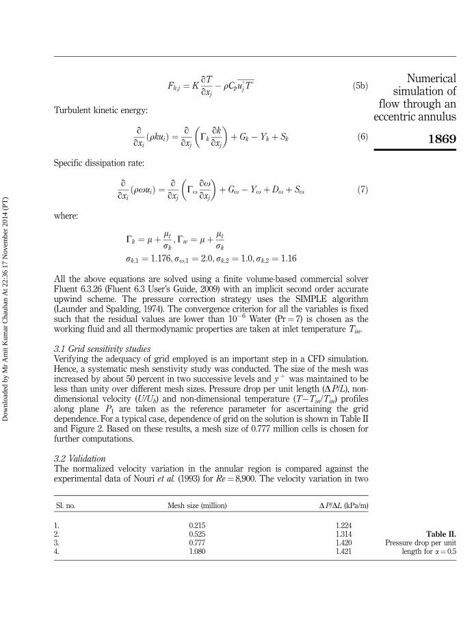
All the above equations are solved using a finite volume-based commercial solverFluent 6.3.26 (Fluent 6.3 User’s Guide, 2009) with an implicit second order accurateupwind scheme. The pressure correction strategy uses the SIMPLE algorithm(Launder and Spalding, 1974). The convergence criterion for all the variables is fixedsuch that the residual values are lower than 10�6 Water (Pr¼ 7) is chosen as theworking fluid and all thermodynamic properties are taken at inlet temperature Tin.
3.1 Grid sensitivity studiesVerifying the adequacy of grid employed is an important step in a CFD simulation.Hence, a systematic mesh senstivity study was conducted. The size of the mesh wasincreased by about 50 percent in two successive levels and yþ was maintained to beless than unity over different mesh sizes. Pressure drop per unit length (DP/L), non-dimensional velocity (U/Ub) and non-dimensional temperature (T�Tin/Tin) profilesalong plane P1 are taken as the reference parameter for ascertaining the griddependence. For a typical case, dependence of grid on the solution is shown in Table IIand Figure 2. Based on these results, a mesh size of 0.777 million cells is chosen forfurther computations.
3.2 ValidationThe normalized velocity variation in the annular region is compared against theexperimental data of Nouri et al. (1993) for Re¼ 8,900. The velocity variation in two
Sl. no. Mesh size (million) DP/DL (kPa/m)
1. 0.215 1.2242. 0.525 1.3143. 0.777 1.4204. 1.080 1.421
Table II.Pressure drop per unit
length for a¼ 0.5
1869
Numericalsimulation of
flow through aneccentric annulus
Dow
nloa
ded
by M
r A
mit
Kum
ar C
hauh
an A
t 22:
36 1
7 N
ovem
ber
2014
(PT
)

planes was chosen along narrow and wide gap regions ( P1 and P2), at the outlet sectionof the channel. This was normalized with respect to the maximum velocity in the sameplane. The results along these two planes are compared against Nouri et al. (1993)(see Figure 3) at the outlet section of the annulus. Note that the, distance is measuredfrom the outer to the inner wall on planes P1 and P2. A good match between theexperimental data and numerical simulations may be noticed. This approach is furtherextended to other simulations involving annular geometric models.
3.3 Data reductionThe engineering parameters of design interest may be expressed in the form of non-dimensional velocity (U*), skin friction coefficient (SFC) (Cf), dimensionlesstemperature (F) and Nusselt number (Nu*) which are defined as follows:
U� ¼ U
Ub
; C�f ¼Cf
ðCf Þavg
;F ¼ T � Tin
Tin
; Nu� ¼ Nu
Nuavgð8Þ
where, Ub, refers to the area averaged velocity at the outlet section. While (Cf)avg andNuavg refers to area averaged SFC and Nusselt number around the inner cylinder at theoutlet section.
U/U
b
Position (X)
0 0.2 0.4 0.6 0.8 10
0.2
0.4
0.6
0.8
1
1.2
Grid 1Grid 2Grid 3Grid 4
(a)
Wal
l She
ar S
tres
s (�
)
Axial Position (z)
0.2 0.4 0.6 0.8 1
1
1.2
1.4
1.6 Grid 1Grid 2Grid 3Grid 4
(b)
Tem
pera
ture
(φ)
Position (X)
0 0.2 0.4 0.6 0.8 10
0.1
0.2
0.3
0.4
0.5
0.6
0.7
Grid 1Grid 2Grid 3Grid 4
(c)Figure 2.(a) Non-dimensionalvelocity along P1 iscompared for differentgrid sizes, to establishmesh senstivity; (b) Non-dimensional wall shearstress along P1 iscompared for differentgrid sizes, to establishmesh senstivity; (c) Non-dimensionalizedtemperature (F) along P1
is plotted for differentgrid sizes
1870
HFF24,8
Dow
nloa
ded
by M
r A
mit
Kum
ar C
hauh
an A
t 22:
36 1
7 N
ovem
ber
2014
(PT
)

4. Results and discussionA detailed analysis and understanding of fluid flow features and heat transfercharacteristics for an annular channel has a wider appeal in a number of engineeringapplications. Numerical simulations are performed in the Reynolds number rangeof 104-106 to study the combined effect of radius ratio and eccentricity on thefluid-thermal characteristics in each sector. The input mass flow rate is adjusted suchthat, for higher values of radius ratio, constant value of Reynolds number ismaintained. This has enabled an easy comparison between different cases. For thepurpose of ease in presentation, fluid flow features are discussed first, followed bythermal characteristics. Influence of constant as well as varying heat flux boundaryconditions are studied.
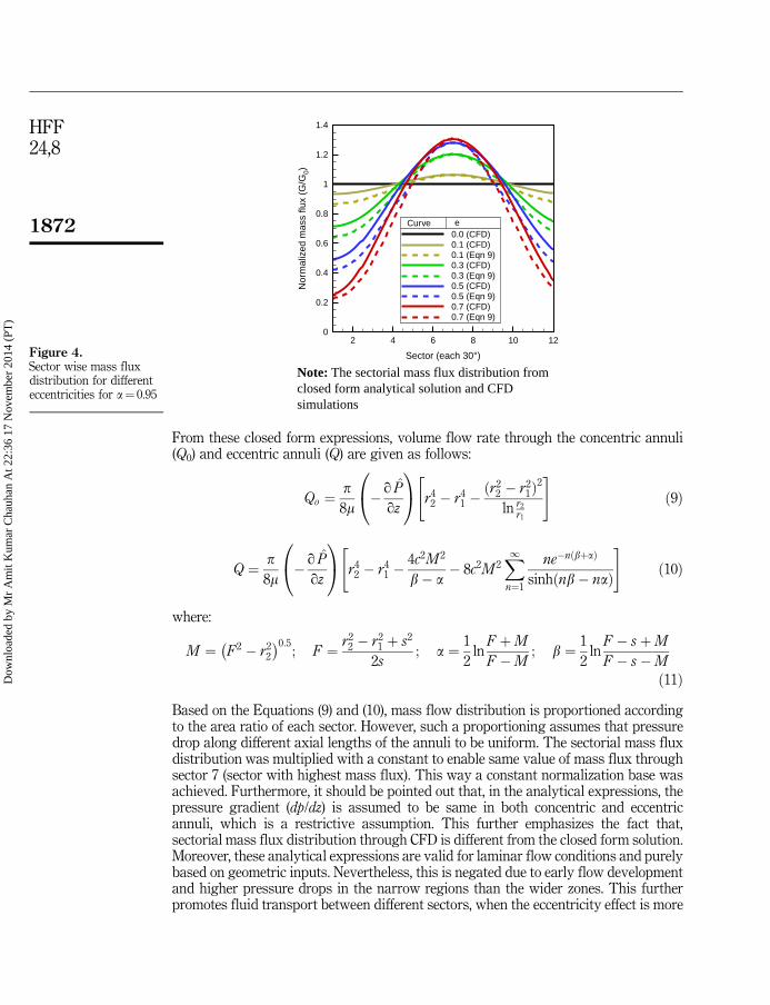
4.1 Fluid flow characteristics4.1.1 Mass flux distribution. A detailed investigation of mass flux distribution indifferent sectors of the annular channel enables a cogent view of flow redistributionand its attendant effects. To further study the flow development, sector wise massflux distribution is carefully examined. To this end, normalized mass flux (G/G0)distribution at the outlet section of the channel is plotted in Figure 4, for a¼ 0.95. Fromthe present CFD simulations, it was observed that, these valus decrease by 75 percentin the narrow gap sector (i.e. sector 1) while about 30 percent increment was noticedin the wide gap sector 7, when compared to the concentric case. While consideringa particular radius ratio, flow squeezes through the narrow gap. However, as thefluid encounters higher resistance, the fluid peripherally gets pushed from thenarrow sectors to the wider sectors. Thus it can be inferred that, for same Re, massflux will be higher in the narrow gap of higher radius ratio, while it will be much lowerthrough the narrow gap region with higher eccentricity. For lower values ofeccentricity, mass flux distribution is almost uniform in both sections, while a largescale shift in mass flux distribution from narrow regions to wide gap regions canbe noticed.
Analytical expressions for volume flow rate (and hence, mass flow rate) as a functionof radius ratio and eccentricity are available in the literature (see White Frank, 2003).
Position (x)
Non
Dim
ensi
onal
ized
Axi
al V
eloc
iy (
U/U
m)
0 0.2 0.4 0.6 0.8 10
0.2
0.4
0.6
0.8
1
1.2
Present (3-4)Nourie et al. (exp)(3-4)Present (1-2)Nourie et al. (exp)(1-2)
Inner wall Outer wall
1 2 3 4x x
Figure 3.Comparison of velocityvariation along narrow
and wide gap planesP1 and P2 against
experimentalmeasurements of Nouri
et al. (1993) for Re¼ 8,900
1871
Numericalsimulation of
flow through aneccentric annulus
Dow
nloa
ded
by M
r A
mit
Kum
ar C
hauh
an A
t 22:
36 1
7 N
ovem
ber
2014
(PT
)
From these closed form expressions, volume flow rate through the concentric annuli(Q0) and eccentric annuli (Q) are given as follows:
Qo ¼p8m
� q P̂
qz
0@
1A r4
2 � r41 �ðr2
2 � r21Þ
2
ln r2
r1
" #ð9Þ
Q ¼ p8m
� q P̂
qz
0@
1A r4
2 � r41 �
4c2M 2
b� a� 8c2M 2
X1n¼1
ne�nðbþaÞ
sinhðnb� naÞ
" #ð10Þ
where:
M ¼ F2 � r22
� �0:5; F ¼ r2
2 � r21 þ s2
2s; a ¼ 1
2ln
F þM
F �M; b ¼ 1
2ln
F � sþM
F � s�M
ð11Þ
Based on the Equations (9) and (10), mass flow distribution is proportioned accordingto the area ratio of each sector. However, such a proportioning assumes that pressuredrop along different axial lengths of the annuli to be uniform. The sectorial mass fluxdistribution was multiplied with a constant to enable same value of mass flux throughsector 7 (sector with highest mass flux). This way a constant normalization base wasachieved. Furthermore, it should be pointed out that, in the analytical expressions, thepressure gradient (dp/dz) is assumed to be same in both concentric and eccentricannuli, which is a restrictive assumption. This further emphasizes the fact that,sectorial mass flux distribution through CFD is different from the closed form solution.Moreover, these analytical expressions are valid for laminar flow conditions and purelybased on geometric inputs. Nevertheless, this is negated due to early flow developmentand higher pressure drops in the narrow regions than the wider zones. This furtherpromotes fluid transport between different sectors, when the eccentricity effect is more
Sector (each 30°)
Nor
mal
ized
mas
s flu
x (G
/G0)
2 4 6 8 10 120
0.2
0.4
0.6
0.8
1
1.2
1.4
0.0 (CFD)0.1 (CFD)0.1 (Eqn 9)0.3 (CFD)0.3 (Eqn 9)0.5 (CFD)0.5 (Eqn 9)0.7 (CFD)0.7 (Eqn 9)
Curve e
Note: The sectorial mass flux distribution fromclosed form analytical solution and CFDsimulations
Figure 4.Sector wise mass fluxdistribution for differenteccentricities for a¼ 0.95
1872
HFF24,8
Dow
nloa
ded
by M
r A
mit
Kum
ar C
hauh
an A
t 22:
36 1
7 N
ovem
ber
2014
(PT
)

pronounced. Comparison of anticipated mass flux distribution is found to differ fromthe CFD predictions. Figure 4 depicts numerical calculations vis-�a-vis closed formsolution. Differences between the two further underscores non-trivial nature of thepresent simulations and the need for a detailed analysis. All of this translates intosector wise Reynolds number (Res) distribution along the periphery, which is shown inFigure 5. It should be mentioned that, mass flow rate and volume flow rate differ by aconstant density multiple for incompressible flows. Furthermore, this variation atteststhe fact that, flow is laminar like in the narrow zone (sector 1), whereas it is fullydeveloped and turbulent like in the wider zone (sector 7).
The sectorial Reynolds number uses a different characteristic length scale unlikethe hydraulic diameter used for the eccentric annulus. In this context, it should bepointed out that, the Reynolds number for the present simulation is 104, which isclearly in the turbulent flow regime. In Figure 5, sectorial Reynolds number ispresented. This observation helps us to realize that, it translates into peripheralvariation in thermal characteristics, which will be discussed in a subsequent section.This result is of practical significance to problems such as rod bundle heat transfer, aslow mass flux is detrimental to the reactivity of the core, as it may lead to departurefrom nucleate boiling (DNB). Furthermore, it would be interesting to study if radiusratio plays a significant role, for a given eccentricity. To this end, the variation of massflux distribution with eccentricity is plotted for different radius ratios in Figure 6. It isobserved that the radius ratio (a) does not have any significant effect on normalizedmass flux distribution. Therefore, it can be concluded that, for different values ofradius ratio, the mass flux distribution is same when eccentricity is varied.
4.1.2 Velocity distribution. The flow redistribution is inevitable either due toeccentricity or radius ratio, which in turn influences the axial velocity distributionalong the channel. The nature of flow development in different sectors of the annularchannel is revealed from the axial velocity color maps, plotted in Figures 7 and 8. Theeffect of eccentricity and radius ratio on flow development can be noticed through thesefigures. Velocity contours at the exit boundary are shown in Figure 8 for four differentradius ratios. As radius ratio is further increased, the velocity distribution increases inall the sectors of the channel. Reynolds number is kept constant, at 104. Essentially, theflow redistributes and adjusts itself in the narrow gap between the cylinders, which is
Sector (each 30°)
Re s
(ρu
bdh)
/μ
2 4 6 8 10 120
200
400
600
800
1,000
1,200
1,400
1,600
0.00.10.30.50.7
Curve e
Figure 5.Sector wise local Reynolds
number distribution fordifferent eccentricities for
a¼ 0.95
1873
Numericalsimulation of
flow through aneccentric annulus
Dow
nloa
ded
by M
r A
mit
Kum
ar C
hauh
an A
t 22:
36 1
7 N
ovem
ber
2014
(PT
)

evident from Figure 8. Stream wise development of the velocity profiles is presented inFigure 9. Due to high eccentricity, significant flow distortions and non-uniformity inflow and temperature distribution in the annular region have been observed byChoudhury and Karki (1992). These features are further revealed through the flowdevelopment depicted in Figure 9.
Eccentricity (e)
Mas
s F
lux
Dis
trib
utio
n (G
/G0)
0 0.2 0.4 0.60
0.2
0.4
0.6
0.8
1
0.500.650.800.95
�
0.33 0.36
0.65
0.66
0.67
0.68
Curve
Figure 6.Normalized mass fluxdistribution in sector 1, fordifferent radius ratios
–0.02–0.02
0.02
1
0.5
0
0 0Y X
U/U
b
–0.02–0.02
0.02
1
0.5
0
0 0Y X
U/U
b
(a) (b)
–0.02–0.02
0.02
1
0.5
0
0 0Y X
U/U
b
–0.02–0.02
0.02
1
0.5
0
0 0Y X
U/U
b
(c) (d)
Figure 7.Non-dimensional velocitycontours for radius ratio(a¼ 0.5) for eccentricity(e)¼ (a) 0.1, (b) 0.3, (c) 0.5and (d) 0.7 at z¼L
1874
HFF24,8
Dow
nloa
ded
by M
r A
mit
Kum
ar C
hauh
an A
t 22:
36 1
7 N
ovem
ber
2014
(PT
)

From a detailed analysis of velocity profiles along the axial length of the annularregion, it can be noticed that, the nature of the flow is turbulent in the wider zone whilelaminarity prevails in the narrow sectors. Corresponding to the flow developmentalong narrow and wider planes, magnitude of velocity is plotted in Figure 10. Figure11(a) depicts the non-dimensional velocity in the narrow gap region along the line P1 atthe outlet section of the annuli. For example, for a typical eccentricity value of 0.7, thefluid velocity is found to increase with increase in a from 0.5 to 0.65 and then itdecreases with further increase in a from 0.65 to 0.95. The reason for this unexpectedbehavior is due to the fact that, with rise in radius ratio upto 0.65, the rise in localinstantaneous velocity is uniform. With further increase in radius ratio (i.e. beyond0.65), as bulk velocity increases, corresponding local velocity does not increase in thesame proportion resulting in a decrease in normalized velocity. The influence of a onthe maximum normalized velocity along P1 is plotted in Figure 11(b). It can be noticedthat higher the eccentricity, lower the maximum velocity. The plot reflects no variationin maximum velocity for different radius ratios. However, for a given radius ratio,higher the eccentricity, lower the maximum velocity. To investigate the bent nature offlow lines from the narrow gap region to wide gap zones, particles were tracked atdifferent downstream positions of the annular channel. The axial lengths were chosen
� = 0.5e = 0.7
–0.02
1
0.5
0
1.5
U/U
b
Y
X
0.02
0 0
–0.02
� = 0.8e = 0.7
–0.01
1
0.5
0
1.5
U/U
b
Y
X
0.01 0.01
00
–0.01
� = 0.65e = 0.7
–0.01
1
0.5
0
1.5
U/U
b
Y
X
0.01 0.01
0 0
–0.01
� = 0.95e = 0.7
–0.01
1
0.5
0
1.5
U/U
bY
X
0.01 0.01
00
–0.01
(a) (b)
(c) (d)
Figure 8.Non-dimensional velocitycontours for eccentricity
(e¼ 0.7) for radius ratio (a)(a) 0.5, (b) 0.65, (c) 0.8 and
(d) 0.95
1875
Numericalsimulation of
flow through aneccentric annulus
Dow
nloa
ded
by M
r A
mit
Kum
ar C
hauh
an A
t 22:
36 1
7 N
ovem
ber
2014
(PT
)

to be 0.25L, 0.5L, 0.75L, L, etc. Moreover, these particle tracks advance in the azimuthaldirection, which is naturally reflective of their axial positions. These are presented inFigures 12 and 13, as viewed from the exit end of the annular region. For the concentriccase, due to uniform fully developed conditions, particle tracks remain along a straightpath. However, at higher values of eccentricity, particles follow curved paths fromnarrow gap side toward wide gap region, indicating the fluid transport toward zonesof lower resistance. This is more pronounced for higher radius ratios at a particulare value of 0.7, as shown in Figure 13.
(a) (b)
1.3
1.3
1.4
1.3
1.3
1.21.1
1.1
0.91
0.9
0.8
0.5
0.4
0.6
1.21.2
0.9
0.8
0.3
0.5
0.8
0.8
1.4
1.4
1.3
1.3
1.2
1.1
1.1
0.7
0.3
0.4
0.6
0.5
0.7
0.4
1.4
1.4
1.3
1.2
1.1
1.2 0.8
0.7
1
0.8
0.5
0.3
0.4
0.6
0.8
U/Ub
Flow
1.4
1.3
1.2
1.1
0.7
0.4
0.7 1
.4
1.2
1.3
10.7
0.4
1.4
1.3
1.1
1.1
0.7
0.3
0.5
0.3
0.5
1.4
1.4
0.5
1.1
1
0.5
1.2
U/Ub
Flow
(d)(c)
1.4
1.4
1.30.9
0.9
0.6
0.6
0.6
1.4
1.2
1.4
0.9
0.6
0.6
0.6
0.6
1.4
1.20.6
1.4
1.2
0.6
0.6
1.4
1.2
1.4
1.2
0.6
0.61.4
1.2
1.3
0.7
1.1
1.4
0.3
0.3
0.2
0.1
0.2
U/Ub
Flow
1.4
1.3
1.2
1.1
0.8
0.4
0.3
0.4
1.4
1.3
1.2 1.0
0.6
0.3
0.4
1.0
1.4
1.4
1.4
1.3
1.2 0.8
0.8
0.6
1.4
1.3
1.0
0.6
0.4
0.61.2
1.4
0.8
0.3
0.4
0.3
U/Ub
Flow
Figure 9.Streamwise flowdevelopment as velocitycontours for (e¼ 0.7) forradius ratio (a) (a) 0.5,(b) 0.65, (c) 0.8 and (d) 0.95at z¼ 0.25L, 0.50L, 0.75L,1.00L respectively
1.8
Position (X)
U/U
b
0 0.2 0.4 0.6 0.8 10
0.2
0.4
0.6
0.8
1
1.2
1.4
1.6
z = 0.00z = 0.25z = 0.50z = 0.75z = 1.00z = 1.25z = 1.50z = 1.75z = 2.00
P1 P2
(a)P1
P2
Position (X)
U/U
b
0 0.2 0.4 0.6 0.8 10
0.2
0.4
0.6
0.8
1
1.2
1.4
1.6
1.8z = 0.00z = 0.25z = 0.75z = 1.25z = 1.75z = 2.00
(b)
Notes: (a) e=0.1 and (b) e=0.7
Figure 10.Non-dimensional velocityalong narrow and widegap planes for a¼ 0.5
1876
HFF24,8
Dow
nloa
ded
by M
r A
mit
Kum
ar C
hauh
an A
t 22:
36 1
7 N
ovem
ber
2014
(PT
)

4.1.3 Variation of friction factor. An investigation of total pressure loss is reflectedthrough the Darcy friction factor, which is found to decrease with e and a as shown inFigure 14(a). Such a decrease is inline with the experimental observations in thestandard literature such as, Lee and Barrow (1963) and Rehme (1973). Kaneda et al.(2003) have pointed out that, in the outer passages of a double pipe heat exchanger, asradius ratio approaches unity, the velocity distribution and friction factor approachesthat of flow between parallel plates. It was observed that, friction factor approaches thevalues of a round tube, when radius ratio approaches zero for both laminar andturbulent flows. Peripheral variation of SFC is found to decrease with increase in e,which are presented in Figure 14(b). However, the variation has similarity and nosignificant change is observed with increase in a when normalized with respect to theaverage value of SFC around the inner cylinder. It can be noticed that, the distributionof SFC around the wall with respect to radius ratio (a) is same. The variation of local
Position (x)
U/U
b
0 0.2 0.4 0.6 0.8 1
0
0.1
0.2
0.3
0.4
0.500.650.800.95
α
(a)
Alpha (�)
(U/U
b)m
ax
0.5 0.6 0.7 0.8 0.90
0.4
0.8
1.2 e = 0.0
e = 0.1
e = 0.3
e = 0.5
e = 0.7
(b)
Curve
Figure 11.(a) Velocity variation in the
narrow gap, along P1,for e¼ 0.7 at z¼L;
(b) distribution ofmaximum velocity with
respect to radius ratio fordifferent eccentricity
values
(a) (b)
(c) (d)
Figure 12.Cross-sectional view ofparticle tracks (as seen
from the exit boundary)for a¼ 0.50 and e¼ (a) 0.0,
(b) 0.3, (c) 0.5 and (d) 0.7
1877
Numericalsimulation of
flow through aneccentric annulus
Dow
nloa
ded
by M
r A
mit
Kum
ar C
hauh
an A
t 22:
36 1
7 N
ovem
ber
2014
(PT
)

wall shear stress is lowest in the narrow sector 1, where the values decrease by 70percent, while maximum in the widest sector 7 where SFC value is higher by 65-70percent as seen from Figure 14(b).
4.1.4 Effect of Reynolds number. In this section, the effect of Reynolds number on theflow and thermal characteristics is analyzed. The cases discussed above are indeedcarried out for a particular Reynolds number of 104. However, it is desirable to extendthe present analysis over a range of Reynolds numbers. To this end, numericalsimulations are performed over the Re range of 104-106. The variation of friction factorwith Re is presented in Figure 15(a) for different radius ratios. There is a steep fall inthe friction factor value between Re¼ 104 to 5.5 � 105 and then it further graduallydecreases with higher Re. This observation is in agreement with previously publishedliterature (see Kaneda et al., 2003; Kelessidis et al., 2011; Rehme, 1973). Figure 15(b)presents variation of SFC around the inner cylinder which is normalized with respect to
(a) (b)
(c) (d)
Figure 13.Cross-sectional view ofparticle tracks (as seenfrom the exit boundary)for e¼ 0.7 and a¼ (a) 0.50;(b) 0.65; (c) 0.80and (d) 0.95
Eccentricity (e)
Dar
cy F
rictio
n Fa
ctor
0 0.2 0.4 0.6 0.8 10.02
0.025
0.03
0.035
0.04
0.500.650.800.95
α
(a)
Angle (�)
Ski
n Fr
ictio
n C
oeffi
cien
t, C
f/(C
f) avg
0 100 200 3000
0.4
0.8
1.2
1.6
2
0.00.10.30.50.7
(b)
Curve
Curve e
Figure 14.(a) Darcy-friction factoragainst eccentricity (e) fordifferent radius ratios (a);(b) variation of skinfriction coefficient aroundthe inner cylinderfor a¼ 0.5
1878
HFF24,8
Dow
nloa
ded
by M
r A
mit
Kum
ar C
hauh
an A
t 22:
36 1
7 N
ovem
ber
2014
(PT
)

the average value. It is found that SFC is almost independent of Reynolds number inthe narrow gap region of the annular channel, while it decreases with Re in the widegap region.
4.2 Thermal characteristicsIn the present simulations, temperature is treated as a passive scalar. Hence, energyequation is decoupled from the momentum equations. Toward thermal characterizationof the present study, two types of practically usefull boundary conditions, namely,uniform heat flux and circumferentially varying heat flux are considered.
4.2.1 Effect of uniform heat flux on the inner cylinder. 4.2.1.1 Temperaturedistribution. In the annular region of the channel, with change in the eccentricity andradius ratio, heat transfer from the inner cylinder to the coolant are indeed functions ofhydrodynamic characteristics. Figure 16 depicts dimensionless isotherms for thecoolant region at the outlet section of the annuli for a typical eccentricity of 0.7. Areduction in flow area, causes an attendant decrease in mass flow rate. Hence, due tolack of sufficient coolant through that sector, heat transfer decreases, which leads to anincrease in temperature of both coolant and the surface temperature of the heated innercylinder. These features are indeed reflected in Figure 16. The above discussion can beeasily understood from the color map of temperature distribution for differenteccentricities and radius ratios at outlet section, which is shown in Figures 16 and 17.On the contrary, in the wider regions of the annulus, the temperature of both fluid andsurface is lower. It can be clearly observed from these plots that at a particular radiusratio, the temperature is maximum on the cylinder surface in the narrow sector 1, whileminimum in the wide gap sector 7. But, for higher radius ratios, flow rate through thenarrow gap increases as the Reynolds number is maintained constant. Although theannular gap is reduced, higher amount of heat is extracted compared to lower radiusratio cases (for the same e). In the present study, the radius ratio range that was studiedis from 0.50 to 0.95. In this range, non-dimensionalized temperature, was observed tobe maximum in case of a¼ 0.50, i.e, 4.5 and minimum for 0.95, i.e. 2.4, in narrowsector 1 (see Figure 17(a) and (b)). Inner cylinder surface is the zone of interest for theanalysis of temperature distribution and its associated gradients, for practicalapplications, such as, nuclear rod bundles, heat exchangers, etc. Figure 18 depicts thedimensionless temperature profile along the circumference of the inner (heated)
Log10 (Re)
Log 1
0(f)
104 105 106
0.01
0.02
0.030.500.650.800.95
Curve �
(a)
Angle (�)
Ski
n Fr
ictio
n C
oeffi
cien
t, C
f/(C
f)avg
0 100 200 3000
0.4
0.8
1.2
1.6
2
1.0X10⁴
5.5X10⁴
1.0X10⁵
5.5X10⁵
1.0X10⁶
(b)
Curve Re Figure 15.(a) Variation of friction
factor for differentReynolds number on
logarithmic scale; (b) skinfriction coefficient along
the inner cylinder, fora¼ 0.8 and e¼ 0.7
1879
Numericalsimulation of
flow through aneccentric annulus
Dow
nloa
ded
by M
r A
mit
Kum
ar C
hauh
an A
t 22:
36 1
7 N
ovem
ber
2014
(PT
)

cylinder with respect to angle (y). It is evident from Figure 18 that, the cylinderencounters maximum temperature where the gap is minimum. It is also observed thatwith increase in eccentricity to 0.7 (e¼ 0.7), for lower radius ratio (a¼ 0.5) temperature(F) rises by 400 percent with reference to the concentric case (see Figure 18a). Such adrastic shoot-up in temperature may lead to change in the physical and mechanicalproperties of both the coolant and cylinder surface. PHWR designs are such that forsafe reactor operations, single phase flow need to be maintained. However, thissituation might change and may lead to undesirable DNB and CHF condition, where inthe coolant enters two phase. It is also observed that, the temperature peak value on theinner cylinder surface in the narrow gap increases uniformly with eccentricity uptoe¼ 0.5. However, this increase is drastic with further increase in e value. For a typicalcase of a¼ 0.5, it is found that, there is an increase in temperature on the cylindersurface by 100 percent upto e¼ 0.5, but it shoots up by 400 percent for e¼ 0.7. Whenthe gap reduces further, beyond e¼ 0.5, the fluid gets squeezed through the narrow gapand tries to escape into wider sectors of the annulus. This results in a reduction in theamount of coolant to extract heat from the cylinder surface. The coolant present in thenarrow gap region gets heated up quickly and thus looses the ability to extract heatany further. This leads to an imminent shoot up in cylinder surface temperature. At thesame time, it is evident from Figure 18 that, with increase in radius ratio, peaktemperature decreases because the coolant flow improves the flow redistribution
(a)� = 0.5e = 0.1
Temperature (φ)
4
2
0
0 0Y X
–0.02 –0.02
(c)� = 0.5e = 0.5
Temperature (φ)
4
2
0
00
Y X–0.02
–0.02
(d)� = 0.5e = 0.7
Temperature (φ)
4
2
0
00
Y X–0.02
–0.02
(b)� = 0.5e = 0.3
Temperature (φ)
4
2
0
0 0Y X
–0.02 –0.02
Figure 16.Non-dimensionalisotherms for radiusratio (a¼ 0.5) fordifferent eccentricityvalues(e)¼ (a) 0.1;(b) 0.3; (c) 0.5and (d) 0.7
1880
HFF24,8
Dow
nloa
ded
by M
r A
mit
Kum
ar C
hauh
an A
t 22:
36 1
7 N
ovem
ber
2014
(PT
)
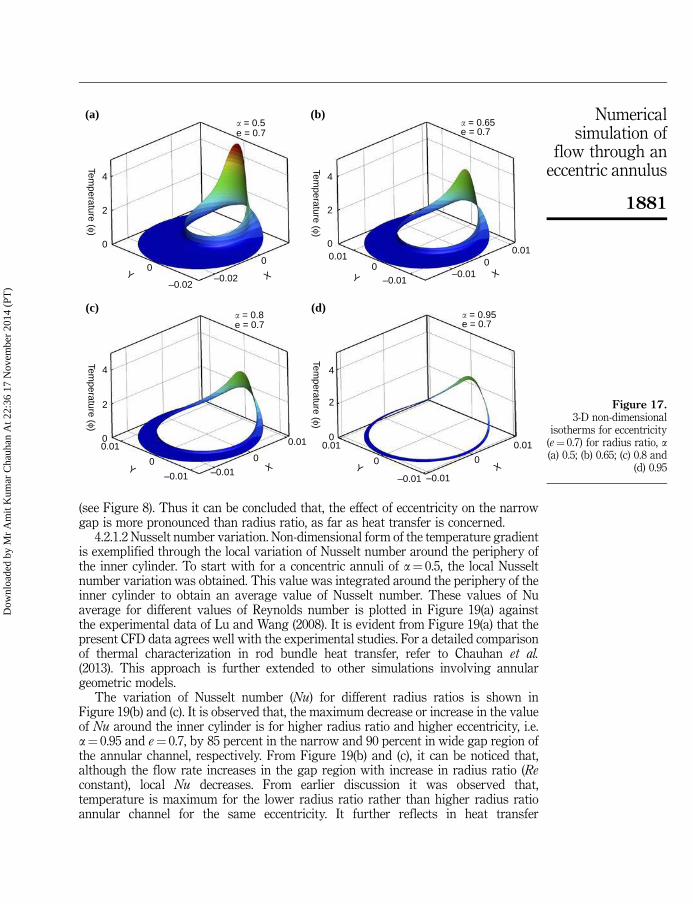
(see Figure 8). Thus it can be concluded that, the effect of eccentricity on the narrowgap is more pronounced than radius ratio, as far as heat transfer is concerned.
4.2.1.2 Nusselt number variation. Non-dimensional form of the temperature gradientis exemplified through the local variation of Nusselt number around the periphery ofthe inner cylinder. To start with for a concentric annuli of a¼ 0.5, the local Nusseltnumber variation was obtained. This value was integrated around the periphery of theinner cylinder to obtain an average value of Nusselt number. These values of Nuaverage for different values of Reynolds number is plotted in Figure 19(a) againstthe experimental data of Lu and Wang (2008). It is evident from Figure 19(a) that thepresent CFD data agrees well with the experimental studies. For a detailed comparisonof thermal characterization in rod bundle heat transfer, refer to Chauhan et al.(2013). This approach is further extended to other simulations involving annulargeometric models.
The variation of Nusselt number (Nu) for different radius ratios is shown inFigure 19(b) and (c). It is observed that, the maximum decrease or increase in the valueof Nu around the inner cylinder is for higher radius ratio and higher eccentricity, i.e.a¼ 0.95 and e¼ 0.7, by 85 percent in the narrow and 90 percent in wide gap region ofthe annular channel, respectively. From Figure 19(b) and (c), it can be noticed that,although the flow rate increases in the gap region with increase in radius ratio (Reconstant), local Nu decreases. From earlier discussion it was observed that,temperature is maximum for the lower radius ratio rather than higher radius ratioannular channel for the same eccentricity. It further reflects in heat transfer
(a)� = 0.5e = 0.7
Temperature (φ)
4
2
0
00
Y X–0.02
–0.02
(c)� = 0.8e = 0.7
Temperature (φ)
4
2
0
0 0Y X
–0.01
0.01
–0.01
0.01 0.01
(d)� = 0.95e = 0.7
Temperature (φ)
4
2
0
0 0Y X
–0.01 –0.01
0.01
(b)� = 0.65e = 0.7
Temperature (φ)
4
2
0
0 0
Y X–0.01
0.01
–0.01
0.01
Figure 17.3-D non-dimensional
isotherms for eccentricity(e¼ 0.7) for radius ratio, a(a) 0.5; (b) 0.65; (c) 0.8 and
(d) 0.95
1881
Numericalsimulation of
flow through aneccentric annulus
Dow
nloa
ded
by M
r A
mit
Kum
ar C
hauh
an A
t 22:
36 1
7 N
ovem
ber
2014
(PT
)

enhancement for higher radius ratio, which contradicts Nu behavior presented inFigure 19(b) and (c). For higher eccentricity values, the fluid escapes from narrow gapsectors toward the wide gap sectors. The local and sectorially average heat transfercoefficients are calculated as follows:
Nuy ¼hl
k; where; Nus ¼
1p6
Zp60
NuðyÞdy; h ¼ q00
Tw � Tf
� � ð12Þ
where:
Tw ¼1
As
ZTdA; Tf ¼
RTr V:dAj jRr V:dAj j ð13Þ
4.2.2 Effect of reynolds number. Thermal characterization is influenced byhydrodynamics, which is analyzed over the Re range of 104-106. A significantvariation in non-dimensional temperature is observed around the inner cylinder
Angle (�)
Tem
pera
ture
(φ)
0 100 200 3000
1
2
3
4
50.00.10.30.50.7
(b)Curve e
Angle (�)
Tem
pera
ture
(φ)
0 100 200 3000
1
2
3
4
50.00.10.30.50.7
(a)Curve e
Angle (�)
Tem
pera
ture
(φ)
0 100 200 3000
1
2
3
4
5
0.00.10.30.50.7
(c)
Curve e
Angle (�)
Tem
pera
ture
(φ)
0 100 200 3000
1
2
3
4
5
0.00.10.30.50.7
(d)
Curve e
Figure 18.Variation of dimensionlesstemperature around theinner cylinder wall fora¼ (a) 0.5; (b) 0.65; (c) 0.8and (d) 0.95
1882
HFF24,8
Dow
nloa
ded
by M
r A
mit
Kum
ar C
hauh
an A
t 22:
36 1
7 N
ovem
ber
2014
(PT
)

surface which is shown in Figure 20(a). It is observed that for lower Re, the flow rate isless and temperature gradient between the cylinder and coolant is less. This results inhigher wall temperature for the narrow gap region. Corresponding Nu variationaround the inner cylinder for a typical case of a¼ 0.8 and e¼ 0.7, is shown in Figure20(b). For higher values of Re, due to better cross-mixing, the Nusselt number variationis more uniform, compared to lower Re values.
4.2.3 Influence of varying heat flux on the inner cylinder. All the simulationsdiscussed so far, involve only constant heat flux boundary condition on the innercylinder. However, in practice heat flux does not remain uniform circumferentially dueto the non-uniform neutron flux distribution along the circumference of the fuel pins.Thus the analysis with circumferentially varying heat flux conditions assumessignificance. Nevertheless, constant heat flux is imposed along the axial direction. Thethermal boundary condition, on the inner cylinder, is therefore specified in the form ofcircumferentially varying heat flux according to cosine law, q00 ¼ qo
00 (1þ 0.5 cosy)(Reynolds, 1963), for which a user defined function was implemented into the boundarycondition. Since the heat flux imposed on the wall is a function of cosy, it has amaximum value of wall heat flux at y¼ 0 (narrow gap zone) while minimum is at 1801(wide gap zone). For the purpose of analysis, this indeed refers to severe condition.
Reynolds number (Re)
Nus
selt
Num
ber
(Nu)
0 100 200 300 4000
2
4
6
8
10Present studyLu and Wang (2008)
(a)
Angle (�)
Nus
selt
Num
ber
( N
u/N
u avg
)
0 100 200 3000
0.5
1
1.5
2
0.00.10.30.50.7
Angle (�)
Nus
selt
Num
ber
(Nu/
Nu a
vg)
0 100 200 3000
0.4
0.8
1.2
1.6
2
0.00.10.30.50.7
eCurve
eCurve
(b) (c)
Figure 19.(a) Comparison of Nusselt
number againstexperimental
measurements of Lu andWang (2008) for Re¼ 10 to
400; (b-c) variation ofNusselt number around
the inner cylinder wall for(b) a¼ 0.5 and (c) a¼ 0.95
1883
Numericalsimulation of
flow through aneccentric annulus
Dow
nloa
ded
by M
r A
mit
Kum
ar C
hauh
an A
t 22:
36 1
7 N
ovem
ber
2014
(PT
)

4.2.3.1 Temperature distribution. The variation of temperature with eccentricity (e)around the inner cylinder is shown in Figure 21. Temperature of the heated wall inthe narrow gap shoots up with increase in eccentricity (e), by 428 percent, when e¼ 0.7for a radius ratio of 0.5. It is higher than the maximum value of temperature in caseof constant heat flux condition by 28 percent. The most interesting part to be notedis that, as the radius ratio increases, the distribution of temperature is observedto be uniform in the wider zone, while for the lower radius ratio the profile ismore pronounced due to the cosine nature of the boundary condition imposed on theinner cylinder. It can be concluded from Figure 21 that, when the pressure tubeof rod bundle is subjected to any thermal or mechanical distortions, it could effect therate of heat transfer depending on the intensity of distortion. Thus temperatureshoot up in the narrow gap zone could be detrimental, as it may lead to unexpectedphase change.
4.2.3.2 Nusselt number variation. The variation of local Nu around the wall of theinner cylinder is presented in Figure 22. It is observed that Nu variation is similar to theprevious case of constant heat flux boundary condition. Nusselt number changes byapproximately 90 percent in the narrow gap and wide gap of the channel. With
Angle (�)
Tem
pera
ture
(φ)
0 100 200 3000
1
2
3
4
1.0×10⁴
5.5×10⁴
1.0×10⁵
5.5×10⁵
1.0×10⁶
Angle (�)
Nus
selt
num
ber
(Nu/
Nu a
vg)
0 100 200 3000
0.4
0.8
1.2
1.6
2
1.0×10⁴
5.5×10⁴
1.0×10⁵
5.5×10⁵
1.0×10⁶
Curve Re
Curve Re
(a) (b)
Figure 20.(a) Variation oftemperature along theinner cylinder for a¼ 0.8and e¼ 0.7; (b) variation ofNu along the innercylinder for a¼ 0.8 ande¼ 0.7
Angle (�)
Tem
pera
ture
(φ)
0 100 200 3000
2
4
6
8
0.00.10.30.50.7
Angle (�)
Tem
pera
ture
(φ)
0 100 200 3000
2
4
6
8
0.00.10.30.50.7
eCurve eCurve
(a) (b)
Figure 21.Variation of dimensionlesswall temperature aroundthe inner cylinder wall fora¼ (a) 0.5 and (b) 0.95,with varying heat flux atthe wall
1884
HFF24,8
Dow
nloa
ded
by M
r A
mit
Kum
ar C
hauh
an A
t 22:
36 1
7 N
ovem
ber
2014
(PT
)
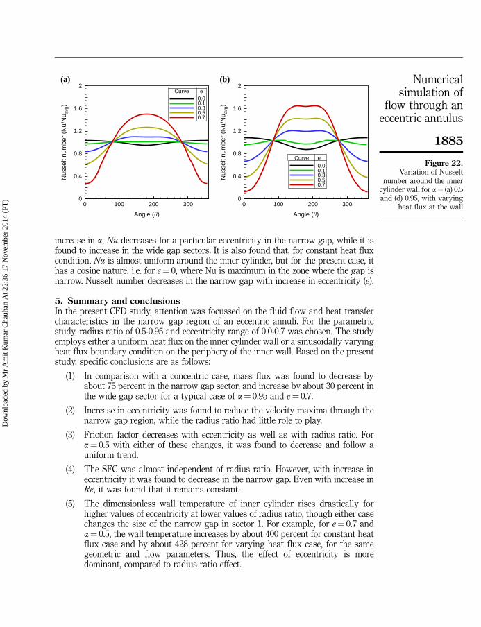
increase in a, Nu decreases for a particular eccentricity in the narrow gap, while it isfound to increase in the wide gap sectors. It is also found that, for constant heat fluxcondition, Nu is almost uniform around the inner cylinder, but for the present case, ithas a cosine nature, i.e. for e¼ 0, where Nu is maximum in the zone where the gap isnarrow. Nusselt number decreases in the narrow gap with increase in eccentricity (e).
5. Summary and conclusionsIn the present CFD study, attention was focussed on the fluid flow and heat transfercharacteristics in the narrow gap region of an eccentric annuli. For the parametricstudy, radius ratio of 0.5-0.95 and eccentricity range of 0.0-0.7 was chosen. The studyemploys either a uniform heat flux on the inner cylinder wall or a sinusoidally varyingheat flux boundary condition on the periphery of the inner wall. Based on the presentstudy, specific conclusions are as follows:
(1) In comparison with a concentric case, mass flux was found to decrease byabout 75 percent in the narrow gap sector, and increase by about 30 percent inthe wide gap sector for a typical case of a¼ 0.95 and e¼ 0.7.
(2) Increase in eccentricity was found to reduce the velocity maxima through thenarrow gap region, while the radius ratio had little role to play.
(3) Friction factor decreases with eccentricity as well as with radius ratio. Fora¼ 0.5 with either of these changes, it was found to decrease and follow auniform trend.
(4) The SFC was almost independent of radius ratio. However, with increase ineccentricity it was found to decrease in the narrow gap. Even with increase inRe, it was found that it remains constant.
(5) The dimensionless wall temperature of inner cylinder rises drastically forhigher values of eccentricity at lower values of radius ratio, though either casechanges the size of the narrow gap in sector 1. For example, for e¼ 0.7 anda¼ 0.5, the wall temperature increases by about 400 percent for constant heatflux case and by about 428 percent for varying heat flux case, for the samegeometric and flow parameters. Thus, the effect of eccentricity is moredominant, compared to radius ratio effect.
Angle (�)
Nus
selt
num
ber
(Nu/
Nu a
vg)
0 100 200 3000
0.4
0.8
1.2
1.6
2
0.0eCurve
eCurve
0.10.30.50.7
Angle (�)N
usse
lt nu
mbe
r (N
u/N
u avg
)
0 100 200 3000
0.4
0.8
1.2
1.6
2
0.00.10.30.50.7
(a) (b)
Figure 22.Variation of Nusselt
number around the innercylinder wall for a¼ (a) 0.5and (d) 0.95, with varying
heat flux at the wall
1885
Numericalsimulation of
flow through aneccentric annulus
Dow
nloa
ded
by M
r A
mit
Kum
ar C
hauh
an A
t 22:
36 1
7 N
ovem
ber
2014
(PT
)

(6) Local Nusselt number increases with increase in Re in the narrow gap regionwhile it decreases in the wide gap region.
References
Barrow, H., Lee, Y. and Roberts, A. (1965), “The similarity hypothesis applied to turbulent flow inan annulus”, International Journal of Heat and Mass Transfer, Vol. 8 No. 12, pp. 1499-1505.
Batra, R.L. and Eissa, M. (1994), “Laminar forced convection heat transfer of a Sutterbymodel fluid in an eccentric annulus”, Mechanics Research Communications, Vol. 21 No. 2,pp. 147-152.
Chauhan, A.K., Prasad, B.V.S.S.S. and Patnaik, B.S.V. (2013), “Thermal hydraulics of rod bundles:the effect of eccentricity”, Nuclear Engineering and Design, Vol. 263, pp. 218-240.
Choudhury, D. and Karki, K. (1992), “Laminar mixed convection in a horizontal eccentricannulus”, Numerical Heat Transfer, Part A: Applications, Vol. 22 No. 1, pp. 87-108.
El-Shaarawi, M.I., Mokheimer, E.M.A. and Jamal, A. (2007), “Geometry effects on conjugatenatural convection heat transfer in vertical eccentric annuli”, International Journal ofNumerical Methods for Heat & Fluid Flow, Vol. 17 No. 5, pp. 461-493.
Fang, P., Manglik, R.M. and Jog, M.A. (1999), “Characteristics of laminar viscous shear-thinning fluidflows in eccentric annular channels”, J. Non-Newtonian Fluid Mech., Vol. 84 No. 1, pp. 1-17.
Fluent 6.3 User’s Guide (2006), Fluent Inc., Lebanon.
Hosseini, R., Nobari, M.R.H. and Hata, M. (2005), “An experimental study of heat transfer in anopen-ended vertical eccentric annulus with insulated and constant heat flux boundaries”,Applied Thermal Engineering, Vol. 25 Nos 8-9, pp. 1247-1257.
Jonsson, V.K. and Sparrow, E.M. (1966), “Experiments on turbulent-flow phenomena in eccentricannular ducts”, Journal of Fluid Mechanics, Vol. 25 No. 1, pp. 65-86.
Kaneda, M., Yu, B., Ozoe, H. and Churchill, S.W. (2003), “The characteristics of turbulent flow andconvection in concentric circular annuli. Part I: flow”, International Journal of Heat andMass Transfer, Vol. 46 No. 26, pp. 5045-5057.
Kelessidis, V.C., Dalamarinis, P. and Maglione, R. (2011), “Experimental study and predictions ofpressure losses of fluids modeled as Herschel-Bulkley in concentric and eccentric annuli inlaminar, transitional and turbulent flows”, Journal of Petroleum Science and Engineering,Vol. 77 Nos 3-4, pp. 305-312.
Launder, B.E. and Spalding, D.B. (1974), “The numerical computation of turbulent flows”,Comput. Methods Appl. Mech. Eng., Vol. 3 No. 2, pp. 269-289.
Lee, B.Y. and Barrow, H. (1963), “Turbulent flow and heat transfer in concentric and eccentricannuli”, Proc Instn Mech Engrs, Vol. 178 No. 1, pp. 1-16.
Lu, G. and Wang, J. (2008), “Experimental investigation on heat transfer characteristics of waterflow in a narrow annulus”, Applied Thermal Engineering, Vol. 28 No. 1, pp. 8-13.
Manglik, R.M. and Fang, P.P. (1995), “Effect of eccentricity and thermal boundary conditions onlaminar fully developed flow in annular ducts”, International Journal of Heat and FluidFlow, Vol. 16 No. 4, pp. 298-306.
Nikitin, N.V., Chernyshenko, S.I. and Wang, H.L. (2009), “Turbulent flow and heat transfer ineccentric annulus”, Journal of Fluid Mechanics, Vol. 132, pp. 601-604.
Ninokata, H., Okumura, T., Merzari, E. and Kano, T. (2005), “Direct numerical simulation ofturbulent flows in an eccentric annulus channel”, Annual Report of the Earth SimulatorCenter, Vol. 25.
Nouri, J.M., Umur, H. and Whitelaw, J.H. (1993), “Flow of Newtonian and non-Newtonian fluids inconcentric and eccentric annuli”, Journal of Fluid Mechanics, Vol. 253, pp. 617-641.
1886
HFF24,8
Dow
nloa
ded
by M
r A
mit
Kum
ar C
hauh
an A
t 22:
36 1
7 N
ovem
ber
2014
(PT
)
Ogino, F., Sakano, T. and Mizushina, T. (1987), “Momentum and heat transfers from fullydeveloped turbulent flow in an eccentric annulus to inner and outer tube walls”, Heat andMass Transfer, Vol. 21 Nos 2-3, pp. 87-93.
Patel, N. and Ingham, D.B. (1983), “Mixed convection flow of a Bingham plastic in an eccentricannulus”, Int. J. Heat and Fluid Flow, Vol. 15 No. 2, pp. 132-141.
Piot, E. and Tavoularis, S. (2011), “Gap instability of laminar flows in eccentric annularchannels”, Nuclear Engineering and Design, Vol. 241 No. 11, pp. 4615-4620.
Rehme, K. (1973), “Simple method of predicting friction factors of turbulent flow in non-circularchannels”, International Journal of Heat and Mass Transfer, Vol. 16 No. 5, pp. 933-950.
Reynolds, W.C. (1963), “Turbulent heat transfer in a circular tube with variable circumferentialheat flux”, International Journal of Heat and Mass Transfer, Vol. 6 No. 6, pp. 445-454.
Sreenivasulu, T. and Prasad, B.V.S.S.S. (2009), “Flow and heat transfer characteristics in anannulus wrapped with a helical wire”, International Journal of Thermal Sciences, Vol. 48No. 7, pp. 1377-1391.
Torii, S. and Yang, W. (1997), “A numerical study on heat transport in turbulent Couette flows inconcentric annuli”, International Journal of Numerical Methods for Heat & Fluid Flow,Vol. 2 No. 2, pp. 81-94.
Trombetta, M.L. (1971), “Laminar forced convection in eccentric annuli”, International Journal ofHeat and Mass Transfer, Vol. 14 No. 8, pp. 1161-1173.
Velusamy, K. and Garg, V.K. (1994), “Entrance flow in eccentric annular ducts”, InternationalJournal For Numerical Methods in Fluids, Vol. 19 No. 6, pp. 493-512.
White Frank, M. (2003), Fluid Mechanics, Mc-Graw Hill, New York.
Yoo, J.S. (2005), “Flow pattern transition of natural convection in a horizontal annulus withconstant heat flux on the inner wall”, International Journal of Numerical Methods for Heat& Fluid Flow, Vol. 15 No. 7, pp. 698-709.
Corresponding authorDr B.S.V. Patnaik can be contacted at: [email protected]
To purchase reprints of this article please e-mail: [email protected] visit our web site for further details: www.emeraldinsight.com/reprints
1887
Numericalsimulation of
flow through aneccentric annulus
Dow
nloa
ded
by M
r A
mit
Kum
ar C
hauh
an A
t 22:
36 1
7 N
ovem
ber
2014
(PT
)
http://www.emeraldinsight.com/action/showLinks?crossref=10.1002%2Ffld.1650190604&isi=A1994PJ67100003