An Energy-Efficient Ant-Based Routing Algorithm for Wireless Sensor Networks
Upload
khangminh22Category
view
0download
0
CR/APP4 | 13.06.2012 | © Robert Bosch GmbH 2011. All rights reserved, also regarding any disposal, exploitation, reproduction, editing, distribution, as well as in the event of applications for industrial property rights.
INTERFLEX
INTERFLEXAn Energy Autonomous and Wireless
System-in-Foil for Air Quality Monitoring
Matthias Mahlich, Metin KoyuncuRobert Bosch GmbH
Corporate Research, Waiblingen, Germany
www.project-interflex.eu, [email protected]
1
CR/APP4 | 13.06.2012 | © Robert Bosch GmbH 2011. All rights reserved, also regarding any disposal, exploitation, reproduction, editing, distribution, as well as in the event of applications for industrial property rights.
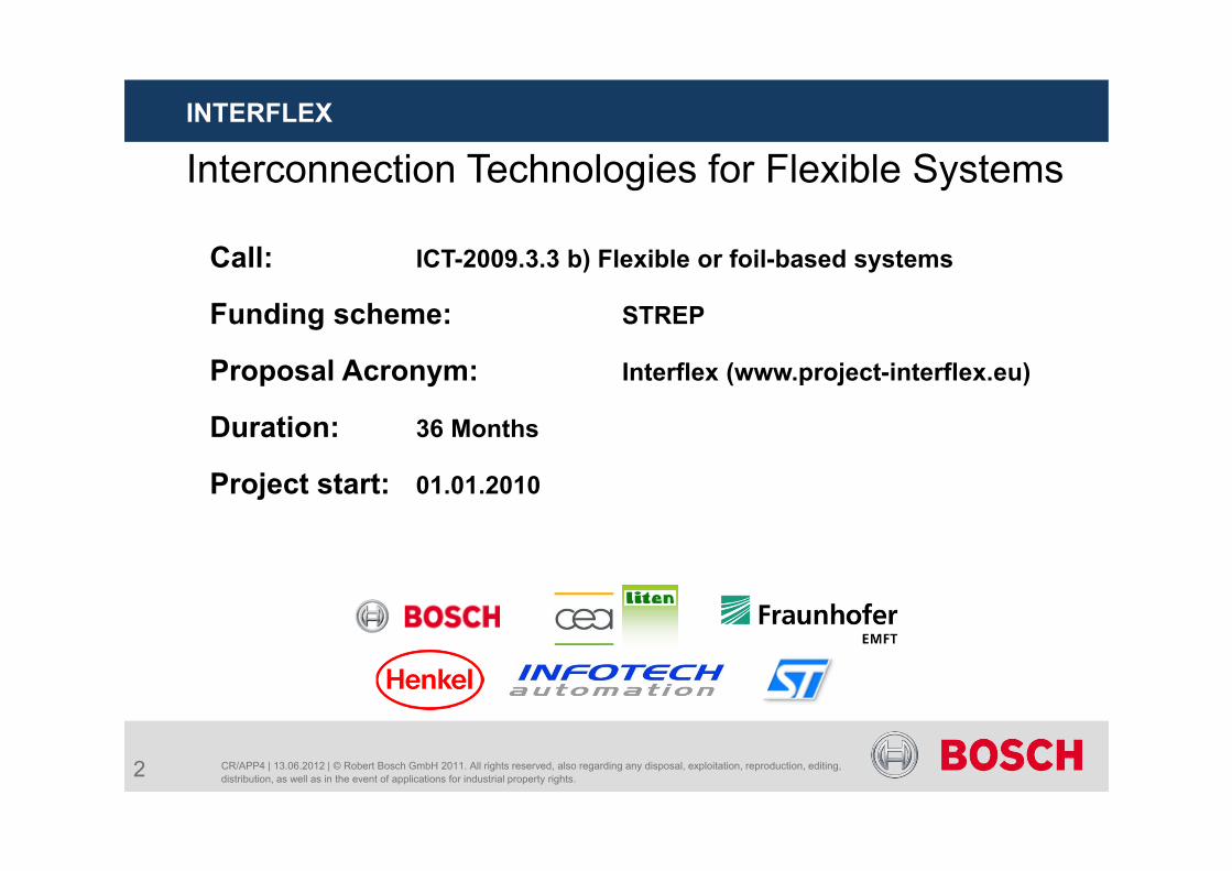
Call: ICT-2009.3.3 b) Flexible or foil-based systems
Funding scheme: STREP
Proposal Acronym: Interflex (www.project-interflex.eu)
Duration: 36 Months
Project start: 01.01.2010
Interconnection Technologies for Flexible SystemsINTERFLEX
2
CR/APP4 | 13.06.2012 | © Robert Bosch GmbH 2011. All rights reserved, also regarding any disposal, exploitation, reproduction, editing, distribution, as well as in the event of applications for industrial property rights.
INTERFLEX
Project Objectives Development of reliable assembly and interconnection technologies
for foil based electronic systems: Interconnection technologies between flexible components and
flexible foils as well as between functional foils. Three dimensional functional foil integration to achieve multi-foil
based systems, i.e. system-in-foil.
Demonstration of the developed technologies with an energy autonomous, indoor air quality sensing system capable of wireless communication of the measured data. Bendable to a bending radius of ½ its maximum dimension
3
CR/APP4 | 13.06.2012 | © Robert Bosch GmbH 2011. All rights reserved, also regarding any disposal, exploitation, reproduction, editing, distribution, as well as in the event of applications for industrial property rights.
INTERFLEX
Outline
Future electronics: not only “more Moore”
Achieving Higher Packaging Density
Emerging Technologies: Polytronics and System-in-Foil
Integration Technologies for a System-in-Foil
Process-Flow for a System-in-Foil
Summary
4
CR/APP4 | 13.06.2012 | © Robert Bosch GmbH 2011. All rights reserved, also regarding any disposal, exploitation, reproduction, editing, distribution, as well as in the event of applications for industrial property rights.
INTERFLEX
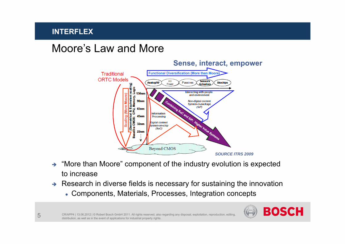
Moore’s Law and More
“More than Moore” component of the industry evolution is expected to increase
Research in diverse fields is necessary for sustaining the innovation Components, Materials, Processes, Integration concepts
SOURCE ITRS 2009
Sense, interact, empower
5
CR/APP4 | 13.06.2012 | © Robert Bosch GmbH 2011. All rights reserved, also regarding any disposal, exploitation, reproduction, editing, distribution, as well as in the event of applications for industrial property rights.
INTERFLEX
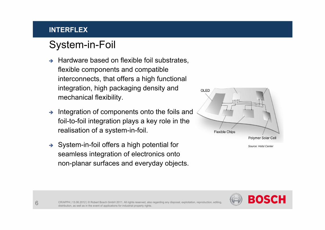
System-in-Foil Hardware based on flexible foil substrates,
flexible components and compatible interconnects, that offers a high functional integration, high packaging density and mechanical flexibility.
Integration of components onto the foils and foil-to-foil integration plays a key role in the realisation of a system-in-foil.
System-in-foil offers a high potential for seamless integration of electronics onto non-planar surfaces and everyday objects.
Source: Holst Center
6
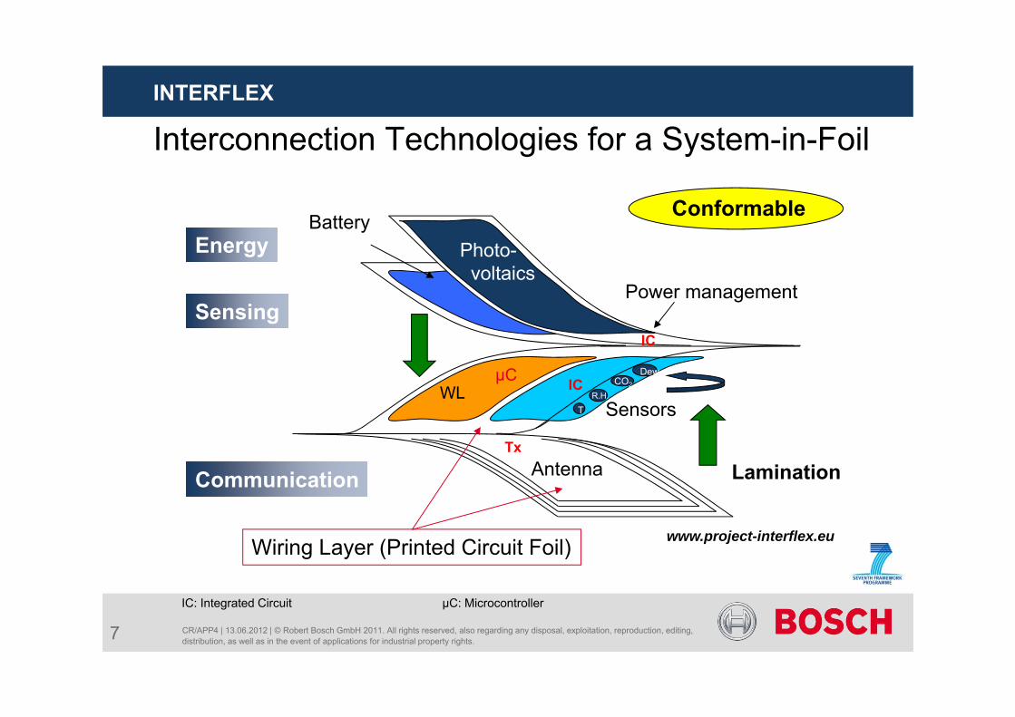
Interconnection Technologies for a System-in-Foil
CR/APP4 | 13.06.2012 | © Robert Bosch GmbH 2011. All rights reserved, also regarding any disposal, exploitation, reproduction, editing, distribution, as well as in the event of applications for industrial property rights.
INTERFLEX
www.project-interflex.eu
Battery
Lamination
Power management
Antenna
SensorsTR.H.
CO2
DewµC
Tx
IC
ICWL
ConformableEnergy
Sensing
Communication
Photo-voltaics
IC: Integrated Circuit µC: Microcontroller
Wiring Layer (Printed Circuit Foil)
7
CR/APP4 | 13.06.2012 | © Robert Bosch GmbH 2011. All rights reserved, also regarding any disposal, exploitation, reproduction, editing, distribution, as well as in the event of applications for industrial property rights.
INTERFLEX
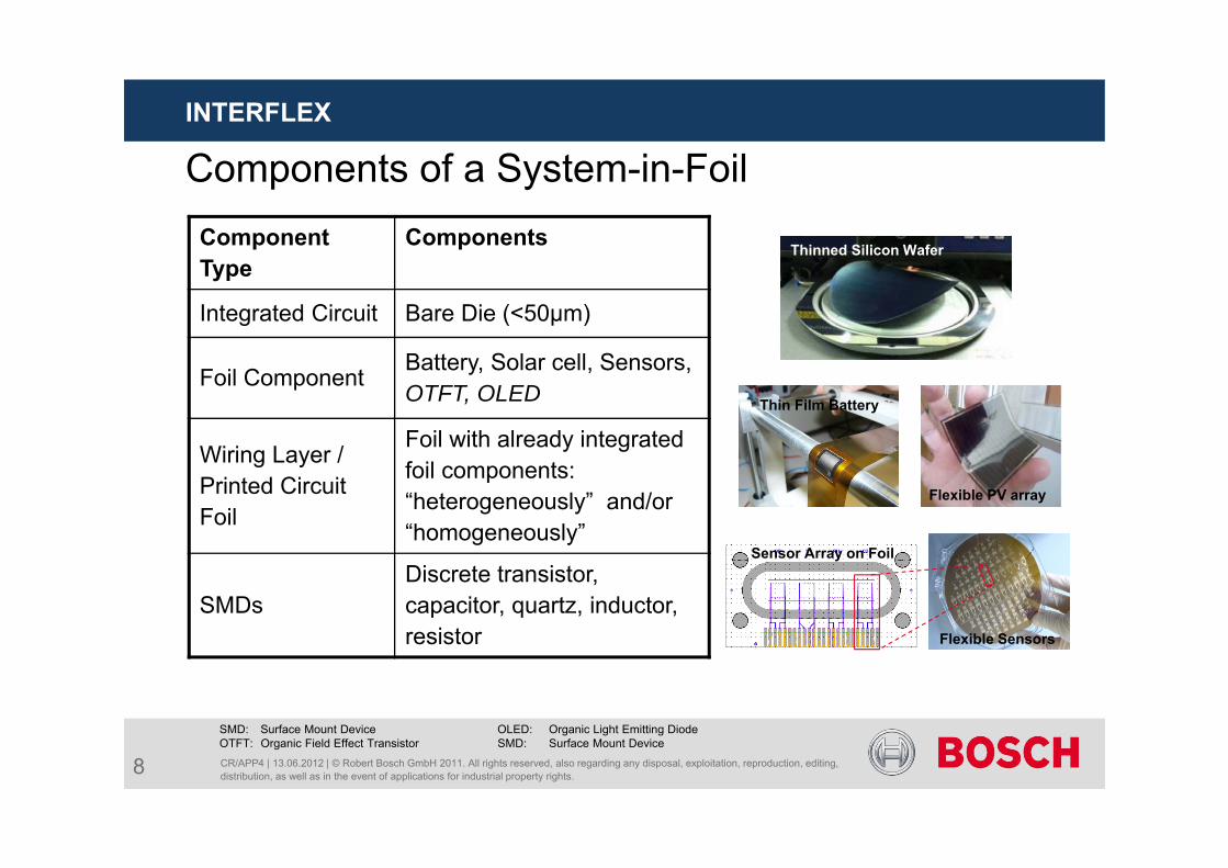
Components of a System-in-FoilComponent Type
Components
Integrated Circuit Bare Die (<50µm)
Foil Component Battery, Solar cell, Sensors, OTFT, OLED
Wiring Layer / Printed Circuit Foil
Foil with already integrated foil components: “heterogeneously” and/or “homogeneously”
SMDsDiscrete transistor, capacitor, quartz, inductor, resistor
SMD: Surface Mount Device OLED: Organic Light Emitting DiodeOTFT: Organic Field Effect Transistor SMD: Surface Mount Device
Flexible PV array
Thinned Silicon Wafer
Flexible Sensors
Sensor Array on Foil
Thin Film Battery
8
CR/APP4 | 13.06.2012 | © Robert Bosch GmbH 2011. All rights reserved, also regarding any disposal, exploitation, reproduction, editing, distribution, as well as in the event of applications for industrial property rights.
INTERFLEX
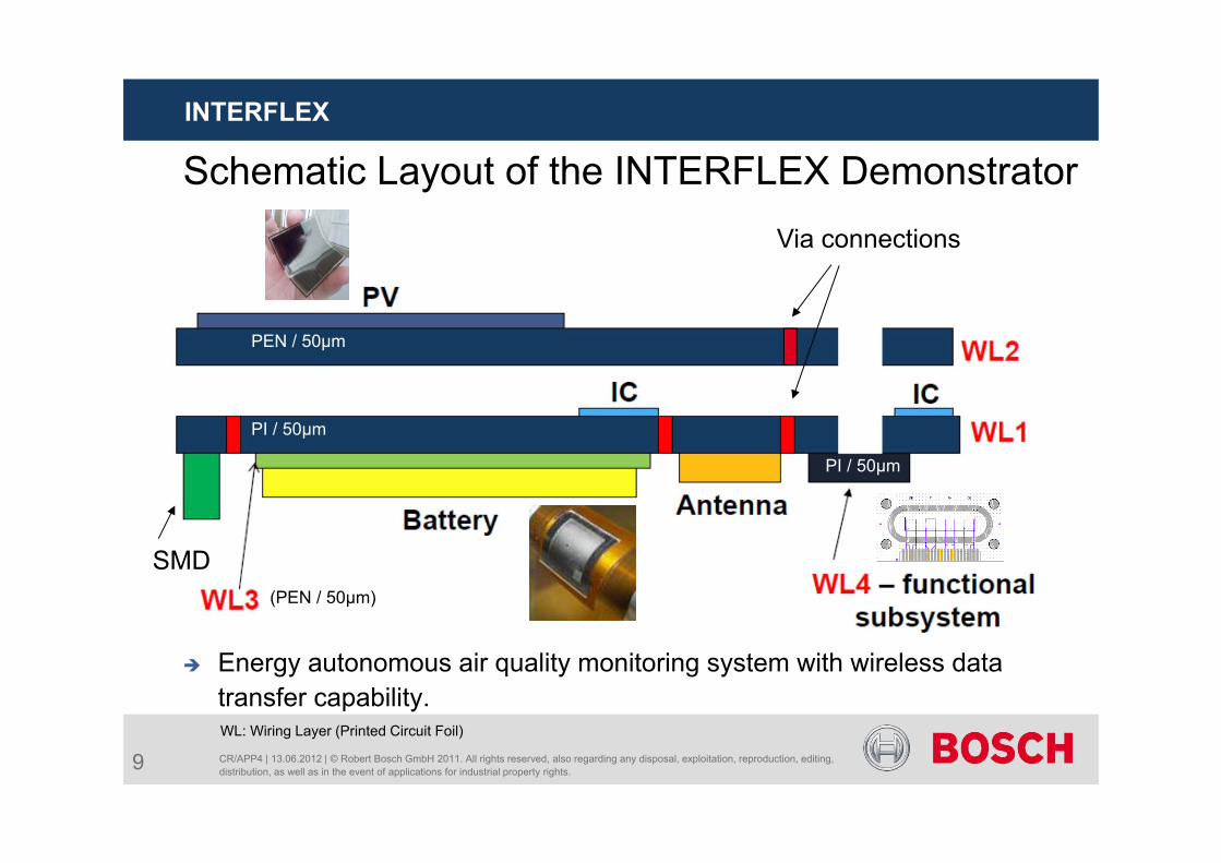
Energy autonomous air quality monitoring system with wireless data transfer capability.
Schematic Layout of the INTERFLEX DemonstratorVia connections
PEN / 50µm
PI / 50µm
PI / 50µm
(PEN / 50µm)
WL: Wiring Layer (Printed Circuit Foil)
SMD
9
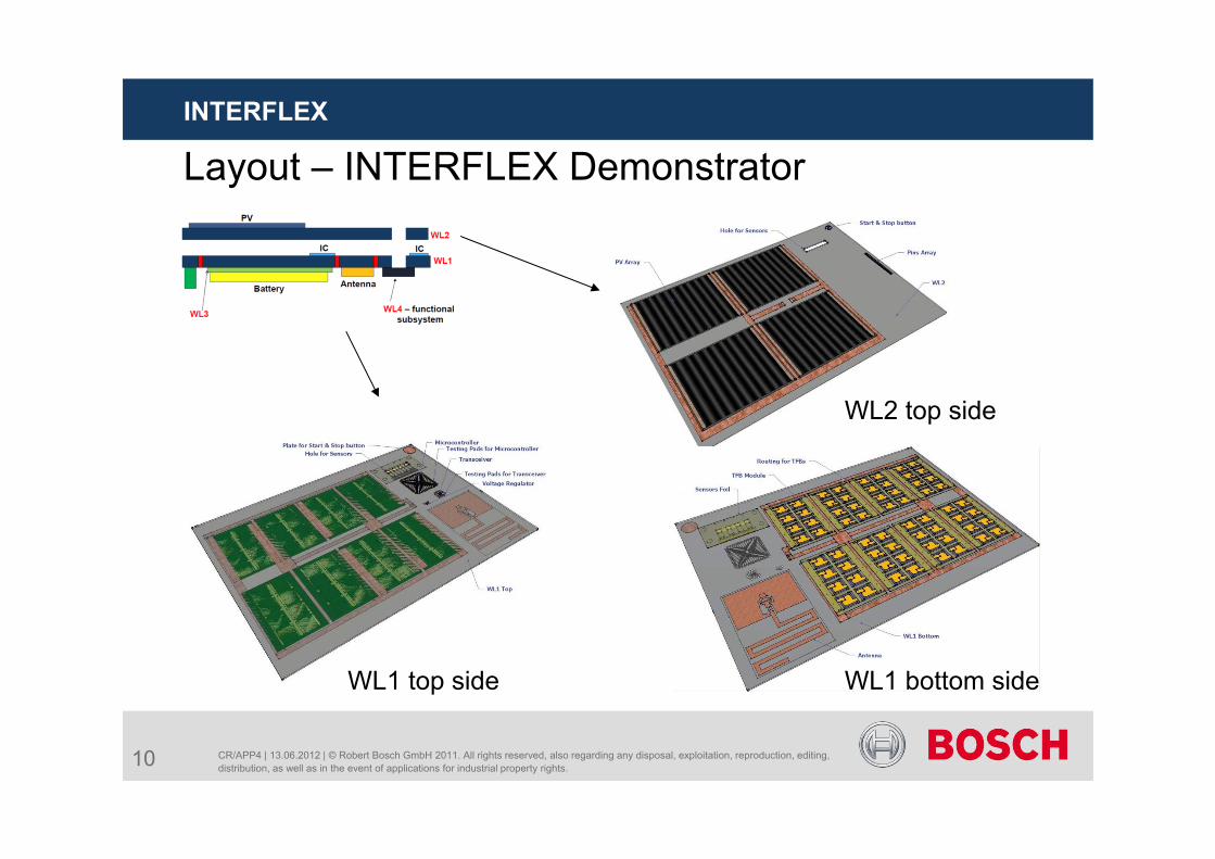
Layout – INTERFLEX Demonstrator
CR/APP4 | 13.06.2012 | © Robert Bosch GmbH 2011. All rights reserved, also regarding any disposal, exploitation, reproduction, editing, distribution, as well as in the event of applications for industrial property rights.
INTERFLEX
WL1 top side WL1 bottom side
10
WL2 top side
CR/APP4 | 13.06.2012 | © Robert Bosch GmbH 2011. All rights reserved, also regarding any disposal, exploitation, reproduction, editing, distribution, as well as in the event of applications for industrial property rights.
INTERFLEX
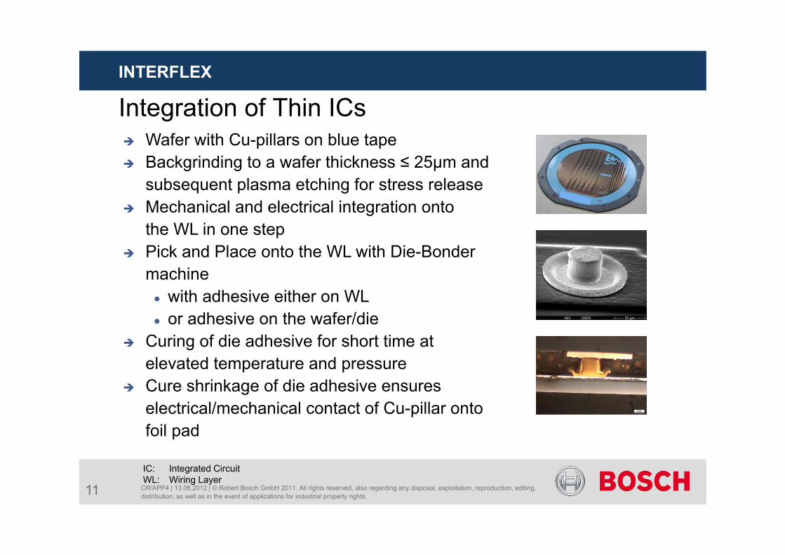
Integration of Thin ICs
IC: Integrated CircuitWL: Wiring Layer
Wafer with Cu-pillars on blue tape Backgrinding to a wafer thickness ≤ 25µm and
subsequent plasma etching for stress release Mechanical and electrical integration onto
the WL in one step Pick and Place onto the WL with Die-Bonder
machine with adhesive either on WL or adhesive on the wafer/die
Curing of die adhesive for short time at elevated temperature and pressure
Cure shrinkage of die adhesive ensures electrical/mechanical contact of Cu-pillar onto foil pad
11
CR/APP4 | 13.06.2012 | © Robert Bosch GmbH 2011. All rights reserved, also regarding any disposal, exploitation, reproduction, editing, distribution, as well as in the event of applications for industrial property rights.
INTERFLEX
12
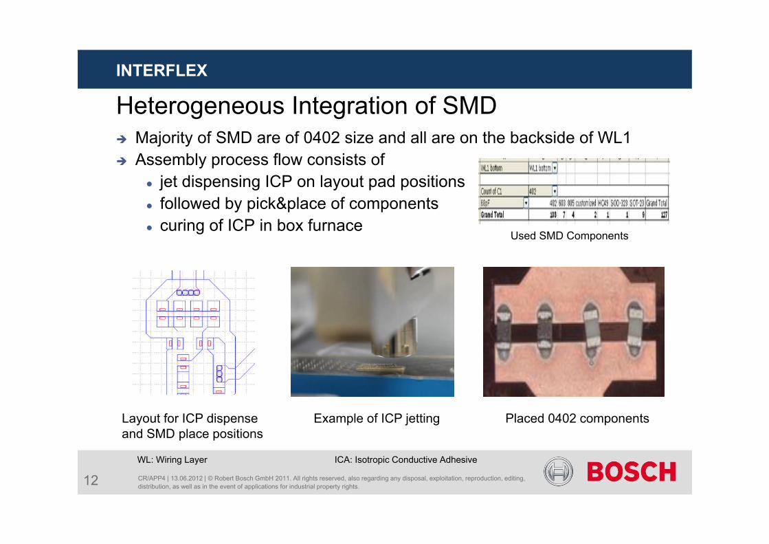
Majority of SMD are of 0402 size and all are on the backside of WL1 Assembly process flow consists of
jet dispensing ICP on layout pad positions followed by pick&place of components curing of ICP in box furnace
WL: Wiring Layer ICA: Isotropic Conductive Adhesive
Layout for ICP dispense and SMD place positions
Placed 0402 components
Used SMD Components
Example of ICP jetting
Heterogeneous Integration of SMD
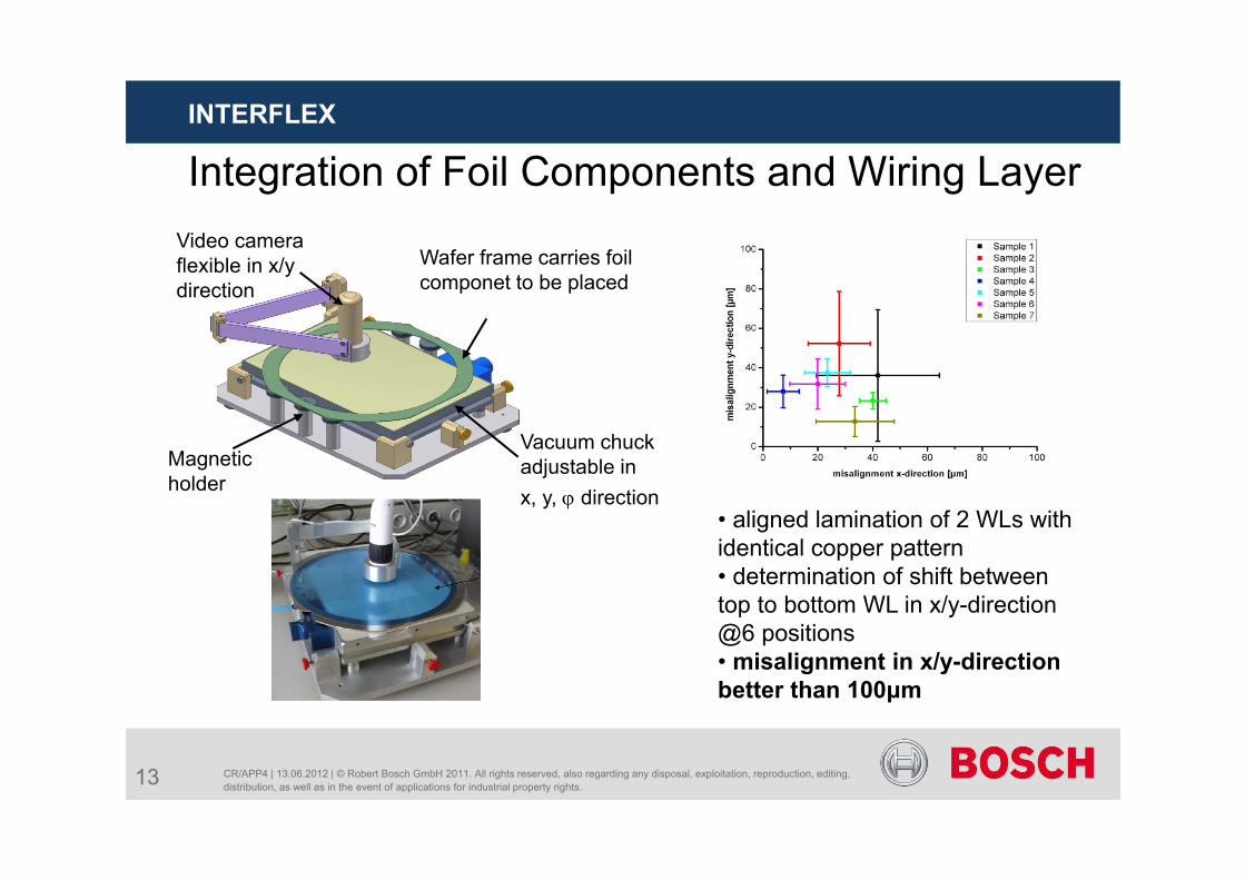
Integration of Foil Components and Wiring Layer
CR/APP4 | 13.06.2012 | © Robert Bosch GmbH 2011. All rights reserved, also regarding any disposal, exploitation, reproduction, editing, distribution, as well as in the event of applications for industrial property rights.
INTERFLEX
13
Video camera flexible in x/y direction
Wafer frame carries foil componet to be placed
Magnetic holder
Vacuum chuckadjustable in x, y, direction
• aligned lamination of 2 WLs with identical copper pattern• determination of shift between top to bottom WL in x/y-direction @6 positions• misalignment in x/y-direction better than 100μm
CR/APP4 | 13.06.2012 | © Robert Bosch GmbH 2011. All rights reserved, also regarding any disposal, exploitation, reproduction, editing, distribution, as well as in the event of applications for industrial property rights.
INTERFLEX
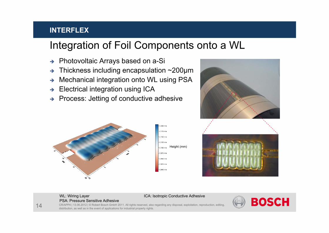
Integration of Foil Components onto a WL Photovoltaic Arrays based on a-Si Thickness including encapsulation ~200µm Mechanical integration onto WL using PSA Electrical integration using ICA Process: Jetting of conductive adhesive
WL: Wiring Layer ICA: Isotropic Conductive AdhesivePSA: Pressure Sensitive Adhesive
Height (mm)
14
CR/APP4 | 13.06.2012 | © Robert Bosch GmbH 2011. All rights reserved, also regarding any disposal, exploitation, reproduction, editing, distribution, as well as in the event of applications for industrial property rights.
INTERFLEX
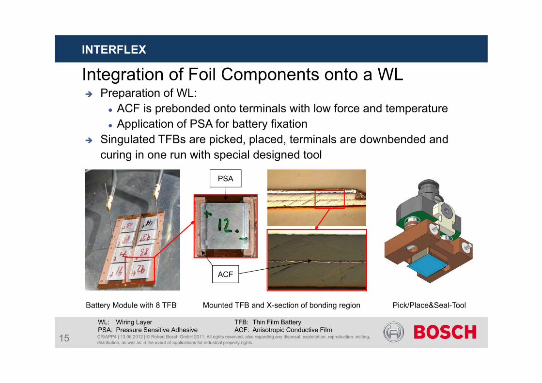
Integration of Foil Components onto a WL
WL: Wiring Layer TFB: Thin Film BatteryPSA: Pressure Sensitive Adhesive ACF: Anisotropic Conductive Film
15
Battery Module with 8 TFB Pick/Place&Seal-ToolMounted TFB and X-section of bonding region
PSA
ACF
Preparation of WL: ACF is prebonded onto terminals with low force and temperature Application of PSA for battery fixation
Singulated TFBs are picked, placed, terminals are downbended and curing in one run with special designed tool
CR/APP4 | 13.06.2012 | © Robert Bosch GmbH 2011. All rights reserved, also regarding any disposal, exploitation, reproduction, editing, distribution, as well as in the event of applications for industrial property rights.
INTERFLEX
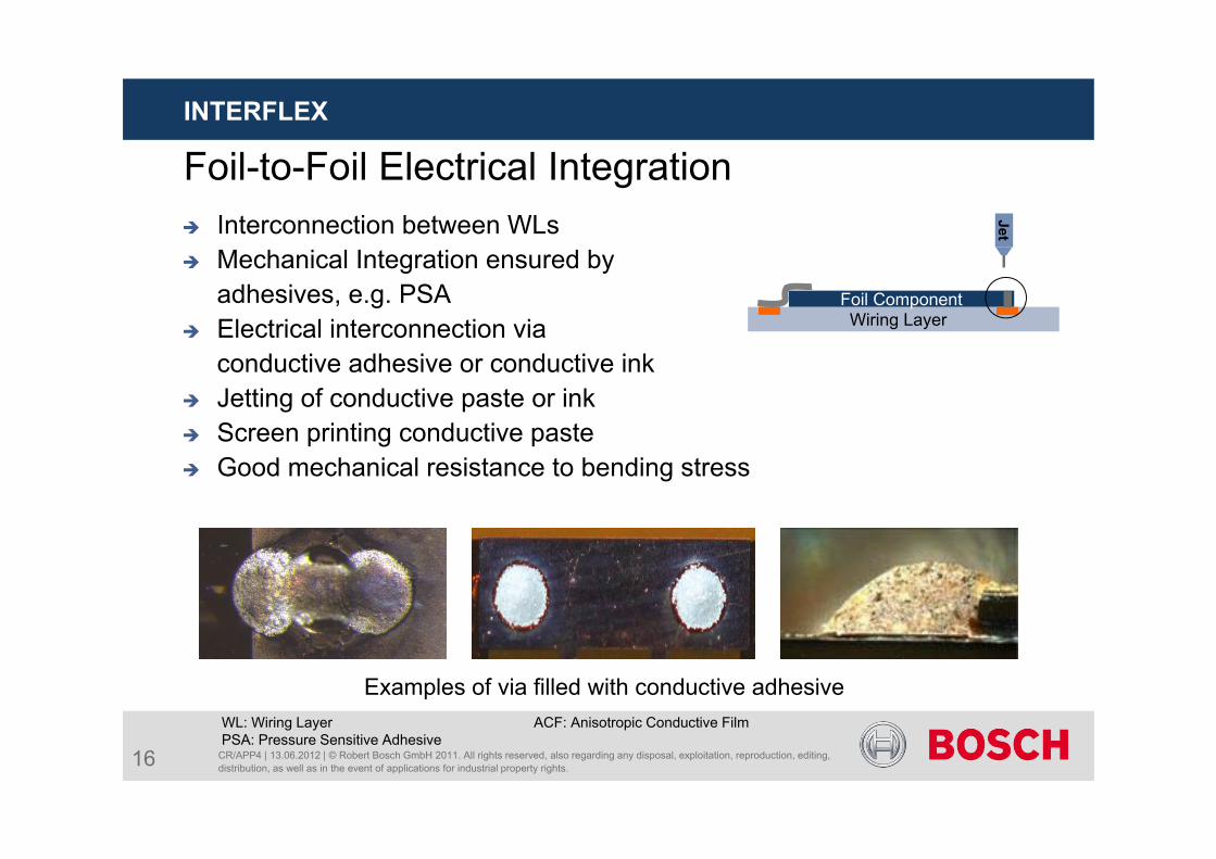
Foil-to-Foil Electrical Integration Interconnection between WLs Mechanical Integration ensured by
adhesives, e.g. PSA Electrical interconnection via
conductive adhesive or conductive ink Jetting of conductive paste or ink Screen printing conductive paste Good mechanical resistance to bending stress
WL: Wiring Layer ACF: Anisotropic Conductive FilmPSA: Pressure Sensitive Adhesive
Examples of via filled with conductive adhesive
Wiring LayerFoil Component
Jet
16
Process Challenges
CR/APP4 | 13.06.2012 | © Robert Bosch GmbH 2011. All rights reserved, also regarding any disposal, exploitation, reproduction, editing, distribution, as well as in the event of applications for industrial property rights.
INTERFLEX
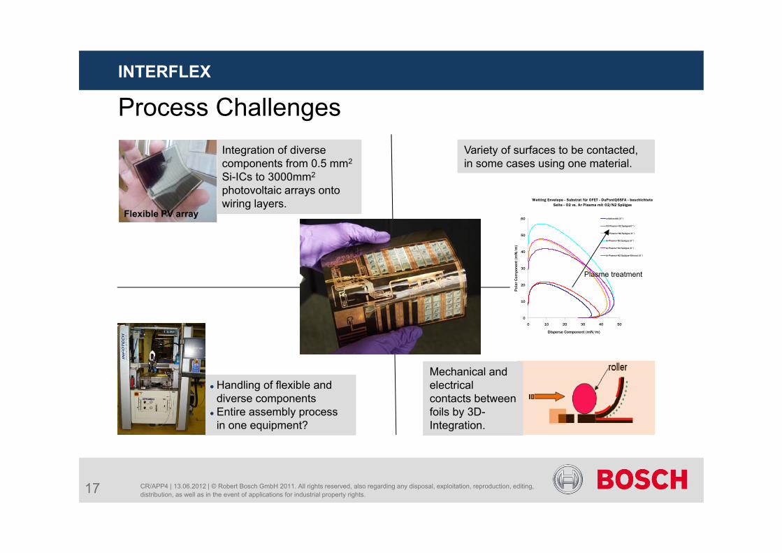
Variety of surfaces to be contacted, in some cases using one material.
Mechanical and electrical contacts between foils by 3D-Integration.
Wetting Envelope - Substrat für OFET - DuPontQ65FA - beschichtete Seite - O2 vs. Ar Plasma mit O2/N2 Spülgas
0
10
20
30
40
50
60
0 10 20 30 40 50
Disperse Component (mN/m)
Pol
ar C
ompo
nent
(mN
/m)
unbehandelt (0°)
O2-Plasma+O2 Spülgas(0°)
O2-Plasma+N2 Spülgas (0°)
Ar-Plasma+N2 Spülgas (0°)
Ar-Plasma+O2 Spülgas (0°)
Ar-Plasma+N2 Spülgas+Ethanol (0°)
Plasme treatment
Handling of flexible and diverse components
Entire assembly process in one equipment?
Integration of diverse components from 0.5 mm2
Si-ICs to 3000mm2
photovoltaic arrays onto wiring layers.
Flexible PV array
17
Challenge of Emergence: System-in-Foil
CR/APP4 | 13.06.2012 | © Robert Bosch GmbH 2011. All rights reserved, also regarding any disposal, exploitation, reproduction, editing, distribution, as well as in the event of applications for industrial property rights.
INTERFLEX
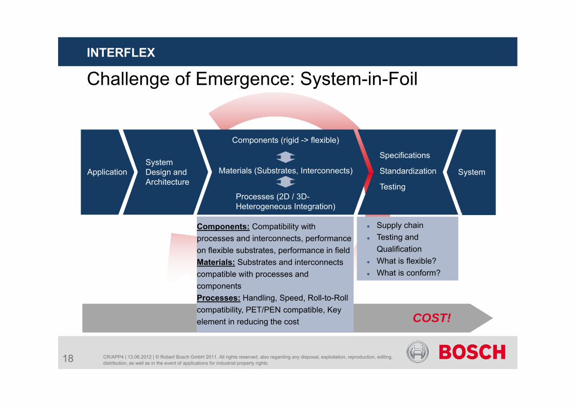
System Design and Architecture
Application Materials (Substrates, Interconnects)
Components (rigid -> flexible)
Processes (2D / 3D-Heterogeneous Integration)
Specifications
Standardization
Testing
System
Components: Compatibility with processes and interconnects, performance on flexible substrates, performance in fieldMaterials: Substrates and interconnects compatible with processes and componentsProcesses: Handling, Speed, Roll-to-Roll compatibility, PET/PEN compatible, Key element in reducing the cost
Supply chain Testing and
Qualification What is flexible? What is conform?
COST!
18
CR/APP4 | 13.06.2012 | © Robert Bosch GmbH 2011. All rights reserved, also regarding any disposal, exploitation, reproduction, editing, distribution, as well as in the event of applications for industrial property rights.
INTERFLEX
Summary System-in-foil offers
Very high functional integration Very high packaging density High potential for seamless integration into everyday life
Still open questions Components Materials and process flow of 2D and 3D integration Supply chain
Interaction between system designers, component developers and processing has to start at a very early stage
19
Copyright © 2022 FDOKUMEN