Intelligent Coordination Method of Multiple Distributed ...
11
J Electr Eng Technol Vol. 7, No. 6: 834-844, 2012 http://dx.doi.org/10.5370/JEET.2012.7.6.834 834 Intelligent Coordination Method of Multiple Distributed Resources for Harmonic Current Compensation in a Microgrid Hyun-Koo Kang * , Choel-Hee Yoo ** , Il-Yop Chung † , Dong-Jun Won *** and Seung-Il Moon * Abstract – Nonlinear electronic loads draw harmonic currents from the power grids that can cause energy loss, miss-operation of power equipment, and other serious problems in the power grids. This paper proposes a harmonic compensation method using multiple distributed resources (DRs) such as small distributed generators (DGs) and battery energy storage systems (BESSs) that are integrated to the power grids through power inverters. For harmonic compensation, DRs should inject additional apparent power to the grids so that certain DRs, especially operated in proximity to their rated power, may possibly reach their maximum current limits. Therefore, intelligent coordination methods of multiple DRs are required for efficient harmonic current compensation considering the power margins of DRs, energy cost, and the battery state-of-charge. The proposed method is based on fuzzy multi- objective optimization so that DRs can cooperate with other DRs to eliminate harmonic currents with optimizing mutually conflicting multi-objectives. Keywords: Harmonic compensation, Multiple distributed resources control, Multi-objective optimization, Microgrid 1. Introduction Power system harmonics are often caused by nonlinear loads that draw significant non-sinusoidal currents from the power grids. Rectifiers, switch-mode power supplies, motor drives, and arc furnaces are notorious for harmonic producing loads. Harmonics might lead to detrimental effects in power grids such as heating in transformer and machines, mal-operation of controllers and protection relays, and interference with radio-frequency circuits especially when harmonic frequencies induce resonant problems in power grids [1-3]. Therefore, there have been many efforts to regulate harmonic current emitted to the grids [4-5]. Power inverters can effectively compensate harmonics because they can flexibly shape the output voltages and currents into certain desired waveforms by fast switching of the power-electronic devices [6-8]. Shunt active power filters are one of the effective power inverter-based harmonic compensators. Recently, due to energy reliability and sustainability issues, DRs such as small distributed generators (DGs), renewable energy sources (RESs) and battery energy storage systems (BESSs) are integrated to the grids [9-11]. Most DRs are interconnected to the grids through power inverters that are required for synchronization and power control. This paper proposes an effective harmonic compensation method by utilizing the multiple power inverter-based DRs in place of power filters. One of the possible advantages of the proposed method is that the installation cost of additional power filters can be relieved. In addition, we have multiple harmonic compensators instead of one solely devoted harmonic filter in the microgrid. There are two important issues of the harmonic compensation using the power inverter-based DRs. First, when the power inverters compensate the harmonics in the grids, the injection current of the power inverters should be increased [8]. Therefore, the power margin of each power inverters should be measured accurately and the amount of harmonic compensation should be distributed appropriately to multiple DRs. Second, DRs have diverse control scheme depending on their types and operational strategies [12-13]. Therefore, the multiple objective functions should be considered to coordinate of multiple DRs. This paper introduces a new intelligent coordination method based on fuzzy multi-objective optimization method. Fuzzy-based optimization methods have been applied to power system coordination problems such as reactive power control, power scheduling, network restoration, and other power system issues [14-16]. To solve our coordination problem, this paper formulates the multi-objective optimization problem using fuzzy sets like as in the previous studies. In addition, the fuzzy † Corresponding Author: School of Electrical Engineering, Kookmin University, Korea. ([email protected]) * School of Electrical Engineering, Seoul National University, Korea. ([email protected], [email protected]) ** School of Electrical Engineering, Kookmin University, Korea. ([email protected]) *** Dept. of Electrical Engineering, INHA University, Korea. ([email protected]) Received: December 8, 2011; Accepted: September 10, 2012 ISSN(Print) 1975-0102 ISSN(Online) 2093-7423
-
Upload
khangminh22 -
Category
Documents
-
view
0 -
download
0
Transcript of Intelligent Coordination Method of Multiple Distributed ...
J Electr Eng Technol Vol. 7, No. 6: 834-844, 2012 http://dx.doi.org/10.5370/JEET.2012.7.6.834
834
Intelligent Coordination Method of Multiple Distributed Resources for
Harmonic Current Compensation in a Microgrid
Hyun-Koo Kang*, Choel-Hee Yoo
**, Il-Yop Chung
†,
Dong-Jun Won***
and Seung-Il Moon*
Abstract – Nonlinear electronic loads draw harmonic currents from the power grids that can cause
energy loss, miss-operation of power equipment, and other serious problems in the power grids. This
paper proposes a harmonic compensation method using multiple distributed resources (DRs) such as
small distributed generators (DGs) and battery energy storage systems (BESSs) that are integrated to
the power grids through power inverters. For harmonic compensation, DRs should inject additional
apparent power to the grids so that certain DRs, especially operated in proximity to their rated power,
may possibly reach their maximum current limits. Therefore, intelligent coordination methods of
multiple DRs are required for efficient harmonic current compensation considering the power margins
of DRs, energy cost, and the battery state-of-charge. The proposed method is based on fuzzy multi-
objective optimization so that DRs can cooperate with other DRs to eliminate harmonic currents with
optimizing mutually conflicting multi-objectives.
Keywords: Harmonic compensation, Multiple distributed resources control, Multi-objective
optimization, Microgrid
1. Introduction
Power system harmonics are often caused by nonlinear
loads that draw significant non-sinusoidal currents from the
power grids. Rectifiers, switch-mode power supplies,
motor drives, and arc furnaces are notorious for harmonic
producing loads. Harmonics might lead to detrimental
effects in power grids such as heating in transformer and
machines, mal-operation of controllers and protection
relays, and interference with radio-frequency circuits
especially when harmonic frequencies induce resonant
problems in power grids [1-3]. Therefore, there have been
many efforts to regulate harmonic current emitted to the
grids [4-5].
Power inverters can effectively compensate harmonics
because they can flexibly shape the output voltages and
currents into certain desired waveforms by fast switching
of the power-electronic devices [6-8]. Shunt active power
filters are one of the effective power inverter-based
harmonic compensators.
Recently, due to energy reliability and sustainability
issues, DRs such as small distributed generators (DGs),
renewable energy sources (RESs) and battery energy
storage systems (BESSs) are integrated to the grids [9-11].
Most DRs are interconnected to the grids through power
inverters that are required for synchronization and power
control. This paper proposes an effective harmonic
compensation method by utilizing the multiple power
inverter-based DRs in place of power filters. One of the
possible advantages of the proposed method is that the
installation cost of additional power filters can be relieved.
In addition, we have multiple harmonic compensators
instead of one solely devoted harmonic filter in the
microgrid.
There are two important issues of the harmonic
compensation using the power inverter-based DRs. First,
when the power inverters compensate the harmonics in the
grids, the injection current of the power inverters should be
increased [8]. Therefore, the power margin of each power
inverters should be measured accurately and the amount of
harmonic compensation should be distributed appropriately
to multiple DRs. Second, DRs have diverse control scheme
depending on their types and operational strategies [12-13].
Therefore, the multiple objective functions should be
considered to coordinate of multiple DRs.
This paper introduces a new intelligent coordination
method based on fuzzy multi-objective optimization
method. Fuzzy-based optimization methods have been
applied to power system coordination problems such as
reactive power control, power scheduling, network
restoration, and other power system issues [14-16]. To
solve our coordination problem, this paper formulates the
multi-objective optimization problem using fuzzy sets like
as in the previous studies. In addition, the fuzzy
† Corresponding Author: School of Electrical Engineering, Kookmin
University, Korea. ([email protected]) * School of Electrical Engineering, Seoul National University, Korea.
([email protected], [email protected]) ** School of Electrical Engineering, Kookmin University, Korea.
*** Dept. of Electrical Engineering, INHA University, Korea. ([email protected])
Received: December 8, 2011; Accepted: September 10, 2012
ISSN(Print) 1975-0102
ISSN(Online) 2093-7423
Hyun-Koo Kang, Choel-Hee Yoo, Il-Yop Chung, Dong-Jun Won and Seung-Il Moon
835
membership functions are designed corresponding to the
design criteria. The proposed method can maximize the
overall satisfaction degree of harmonic compensation of
DRs. The performance of the proposed coordination
method is verified via simulation studies with a detailed
simulation model of a microgrid including a PV, two small
DGs, a BESS and a nonlinear load.
2. Microgrid Configuration
2.1 Microgrid configuration and operation
Microgrids are state-of-the-art power distribution
networks that consist of multiple DRs and sensitive power
loads. The goal of microgrid operation is to provide electric
power to the loads with high reliability regardless of
abnormal operations in the power grids. From the
perspective of the grids, microgrids can be considered as
autonomous cells that can be operated by independent
operators based on power exchange contracts. This
configuration gives advantages to both the power grids and
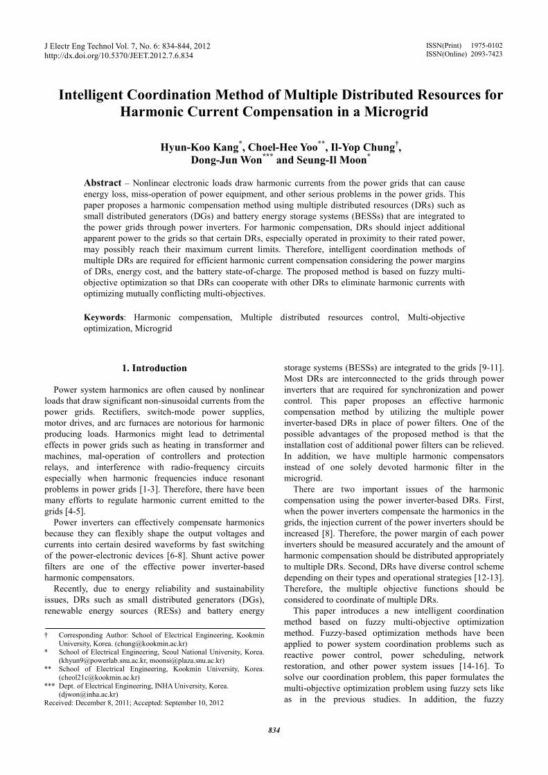
the microgrids [9-11]. Fig. 1 illustrates a single-line
diagram of a microgrid that contains a photovoltaic (PV)
system, two small inverter-interfaced DGs, a BESS and a
nonlinear load.
The nonlinear load represents electronic loads that
commonly employ power conversion circuits such as
rectifiers and switching-mode power supplies. They draw
significant harmonic currents steadily during their
operation. The power grid and the neighbor power facility
can suffer severe harmonic problems. A common
countermeasure is to install passive or active power filters
near the nonlinear loads to keep harmonic currents from
flowing into the grid and the adjacent feeders. Passive
filters can be the cheapest solution when it comes to single
harmonic component elimination but it is hard to
compensate various harmonic components at the same time.
Active power filters are an effective solution but the
installation and management are costly. The basic idea of
this paper is to utilize the local inverter-interfaced DRs to
compensate multiple harmonic components. The system
operator can save the installation cost of additional power
filters and also can have multiple distributed compensators
in the microgrid.
2.2 PV system model
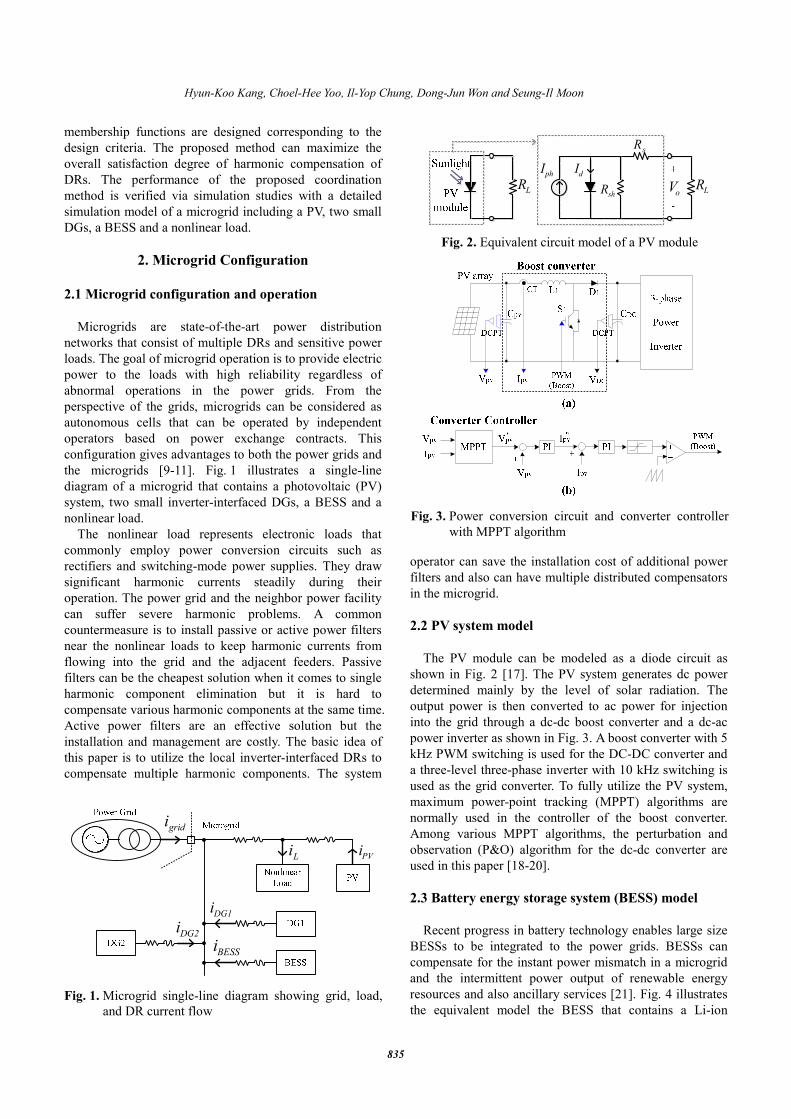
The PV module can be modeled as a diode circuit as
shown in Fig. 2 [17]. The PV system generates dc power
determined mainly by the level of solar radiation. The
output power is then converted to ac power for injection
into the grid through a dc-dc boost converter and a dc-ac
power inverter as shown in Fig. 3. A boost converter with 5
kHz PWM switching is used for the DC-DC converter and
a three-level three-phase inverter with 10 kHz switching is
used as the grid converter. To fully utilize the PV system,
maximum power-point tracking (MPPT) algorithms are
normally used in the controller of the boost converter.
Among various MPPT algorithms, the perturbation and
observation (P&O) algorithm for the dc-dc converter are
used in this paper [18-20].
2.3 Battery energy storage system (BESS) model
Recent progress in battery technology enables large size
BESSs to be integrated to the power grids. BESSs can
compensate for the instant power mismatch in a microgrid
and the intermittent power output of renewable energy
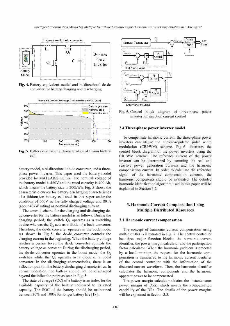
resources and also ancillary services [21]. Fig. 4 illustrates
the equivalent model the BESS that contains a Li-ion
Li PVi
DG1i
DG2i
BESSi
gridi
Fig. 1. Microgrid single-line diagram showing grid, load,
and DR current flow
phI dI
shR
sR
LRLR oV
Fig. 2. Equivalent circuit model of a PV module
Fig. 3. Power conversion circuit and converter controller
with MPPT algorithm
Intelligent Coordination Method of Multiple Distributed Resources for Harmonic Current Compensation in a Microgrid
836
battery model, a bi-directional dc-dc converter, and a three-
phase power inverter. This paper used the battery model
provided by MATLAB/Simulink. The nominal voltage of
the battery model is 480V and the rated capacity is 400 Ah,
which means the battery size is 200kWh. Fig. 5 shows the
characteristic curves for battery discharging characteristics
of a lithium-ion battery cell used in this paper under the
condition of 560V as the fully charged voltage and 80 A
(about 40kW rating) as nominal discharging current.
The control scheme for the charging and discharging dc-
dc converter for the battery model is as follows. During the
charging period, the switch Q1 operates as a switching
device whereas the Q2 acts as a diode of a buck converter.
Therefore, the dc-dc converter operates in the buck mode.
As shown in Fig. 5, the dc-dc converter controls the
charging current in the beginning. When the battery voltage
reaches a certain level, the dc-dc converter controls the
battery voltage as constant. During the discharging period,
the dc-dc converter operates in the boost mode: the Q2
switches while the Q1 operates as a diode of a boost
converter. In the discharging characteristics, there is an
inflection point in the battery discharging characteristics. In
normal operation, the battery should not be discharged
beyond the inflection point as seen in Fig. 5.
The state of charge (SOC) of a battery is an index for the
available capacity of the battery compared to its rated
capacity. The SOC of the battery should be maintained
between 30% and 100% for longer battery life [18].
2.4 Three-phase power inverter model
To compensate harmonic current, the three-phase power
inverters can utilize the current-regulated pulse width
modulation (CRPWM) scheme. Fig. 6 illustrates the
control block diagram of the power inverters using the
CRPWM scheme. The reference current of the power
inverter can be determined by summing the real and
reactive power generation currents and the harmonic
compensation current. In order to calculate the reference
signal of the harmonic compensation currents, the
harmonic components should be evaluated. The detailed
harmonic identification algorithm used in this paper will be
explained in Section 3.2.
3. Harmonic Current Compensation Using
Multiple Distributed Resources
3.1 Harmonic current compensation
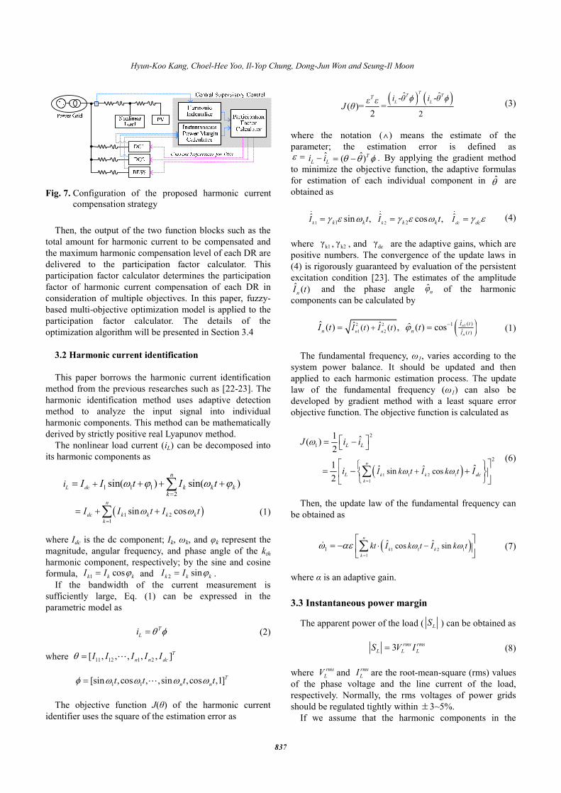
The concept of harmonic current compensation using
multiple DRs is illustrated in Fig. 7. The central controller
has three major function blocks: the harmonic current
identifier, the power margin calculator and the participation
factor calculator. When the harmonic problem is detected
by a local monitor, the request for the harmonic com-
pensation is transferred to the harmonic current identifier
of the central controller with the information of the
distorted current waveform. Then, the harmonic identifier
calculates the harmonic components and the harmonic
apparent power to be compensated.
The power margin calculator obtains the instantaneous
power margin of DRs, which means the compensation
capability of the DRs. The details of the power margins
will be explained in Section 3.3.
Fig. 4. Battery equivalent model and bi-directional dc-dc
converter for battery charging and discharging
Fig. 5. Battery discharging characteristics of Li-ion battery
cell
Li~
referenceP
tmeasuremenPPCCV
Pi
referencei
tmeasuremeni
referenceQ
tmeasuremenQPCCV
QincePCC_refereV
ementPCC_measurV
Fig. 6. Control block diagram of three-phase power
inverter for injection current control
Hyun-Koo Kang, Choel-Hee Yoo, Il-Yop Chung, Dong-Jun Won and Seung-Il Moon
837
Then, the output of the two function blocks such as the
total amount for harmonic current to be compensated and
the maximum harmonic compensation level of each DR are
delivered to the participation factor calculator. This
participation factor calculator determines the participation
factor of harmonic current compensation of each DR in
consideration of multiple objectives. In this paper, fuzzy-
based multi-objective optimization model is applied to the
participation factor calculator. The details of the
optimization algorithm will be presented in Section 3.4
3.2 Harmonic current identification
This paper borrows the harmonic current identification
method from the previous researches such as [22-23]. The
harmonic identification method uses adaptive detection
method to analyze the input signal into individual
harmonic components. This method can be mathematically
derived by strictly positive real Lyapunov method.
The nonlinear load current (iL) can be decomposed into
its harmonic components as
1 1 12
sin( ) sin( )L dc
n
k k kk
i I I t I tω ϕ ω ϕ=
+= + + +∑
( )1 2
1
sin cosn
dc k k k k
k
I I t I tω ω=
= + +∑ (1)
where Idc is the dc component; Ik, ωk, and φk represent the
magnitude, angular frequency, and phase angle of the kth
harmonic component, respectively; by the sine and cosine
formula, 1cos
k k kI I ϕ= and 2
sink k kI I ϕ= .
If the bandwidth of the current measurement is
sufficiently large, Eq. (1) can be expressed in the
parametric model as
T
Li θ φ= (2)
where 11 12 1 2[ , , , , , ]T
n n dcI I I I Iθ = L
1 1[sin ,cos , ,sin ,cos ,1]T
n nt t t tφ ω ω ω ω= L
The objective function J(θ) of the harmonic current
identifier uses the square of the estimation error as
( ) ( )ˆ ˆ- -
2( )= =
2
TT T
L LT i θ i θε ε
J θφ φφ
(3)
where the notation (∧) means the estimate of the
parameter; the estimation error is defined as ε = ˆ
L Li i− ˆ( )Tθ θ φ= − . By applying the gradient method
to minimize the objective function, the adaptive formulas
for estimation of each individual component in θ̂ are
obtained as
1 21 2
ˆ ˆ ˆsin , cos ,k k dck k k k dcI I It tγ ε ω γ ε ω γ ε= = =& & &
(4)
where k1γ , k2
γ , and dcγ are the adaptive gains, which are
positive numbers. The convergence of the update laws in
(4) is rigorously guaranteed by evaluation of the persistent
excitation condition [23]. The estimates of the amplitude ˆ ( )nI t and the phase angle ˆ
nφ of the harmonic
components can be calculated by
( )12 2
1 2
ˆ ( )1
ˆ ( )
ˆ ˆ( ) ( )ˆ ˆ( ) , ( ) cos n
nn n
I t
n n I tI t I tI t tϕ −+= = (1)
The fundamental frequency, ω1, varies according to the
system power balance. It should be updated and then
applied to each harmonic estimation process. The update
law of the fundamental frequency (ω1) can also be
developed by gradient method with a least square error
objective function. The objective function is calculated as
( )1 1 2 1
1
2
1
2
ˆ ˆsin cos
1 ˆ( )2
1 ˆ2
n
k k
k
L L
L dcI k t I k t
J i i
i Iω ω
ω
=
+
= −
= − +
∑
(6)
Then, the update law of the fundamental frequency can
be obtained as
( )1 1 2 1
1
1ˆ ˆcos sin
n
k k
k
kt I k t I k tω ωω αε=
⋅ −
= − ∑& (7)
where α is an adaptive gain.
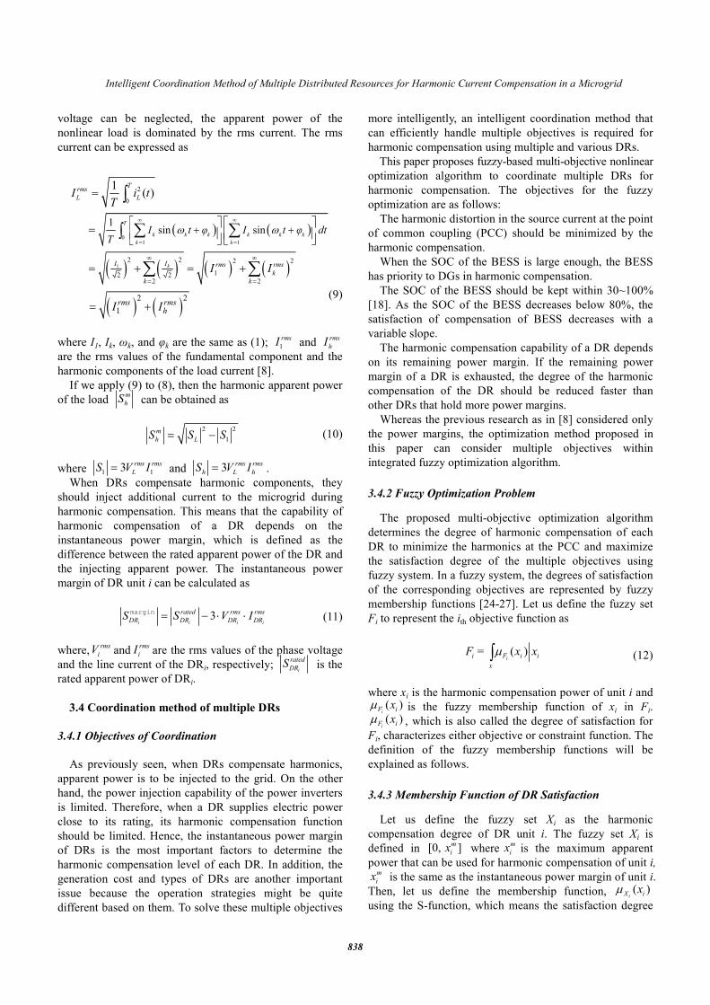
3.3 Instantaneous power margin The apparent power of the load ( L
S ) can be obtained as
3rms rms
L L LS V I= (8)
where rms
LV and
rms
LI are the root-mean-square (rms) values
of the phase voltage and the line current of the load,
respectively. Normally, the rms voltages of power grids
should be regulated tightly within ±3~5%.
If we assume that the harmonic components in the
Fig. 7. Configuration of the proposed harmonic current
compensation strategy
Intelligent Coordination Method of Multiple Distributed Resources for Harmonic Current Compensation in a Microgrid
838
voltage can be neglected, the apparent power of the
nonlinear load is dominated by the rms current. The rms
current can be expressed as
( ) ( )
( ) ( ) ( ) ( )1
01 1
2
0
2 2 2 2
12 22 2
1sin sin
1( )
k
T
k k k k k k
k k
Trms
L L
II rms rms
k
k k
I t φ I t φ dtT
I i tT
I I
ω ω∞ ∞
= =
∞ ∞
= =
+ +
=
=
= + = +
∑ ∑∫
∫
∑ ∑
( ) ( )2 2
1rms rms
hI I= + (9)
where I1, Ik, ωk, and φk are the same as (1); 1
rmsI and rms
hI
are the rms values of the fundamental component and the
harmonic components of the load current [8].
If we apply (9) to (8), then the harmonic apparent power
of the load m
hS can be obtained as
2 2
1
m
h LS S S= − (10)
where 1 13
rms rms
LS V I= and 3
rms rms
h L hS V I= .
When DRs compensate harmonic components, they
should inject additional current to the microgrid during
harmonic compensation. This means that the capability of
harmonic compensation of a DR depends on the
instantaneous power margin, which is defined as the
difference between the rated apparent power of the DR and
the injecting apparent power. The instantaneous power
margin of DR unit i can be calculated as
3i i i i
rated rms rms
DR DR DR DRS S V I= − ⋅ ⋅margin (11)
where,rms
iV and
rms
iI are the rms values of the phase voltage
and the line current of the DRi, respectively; i
rated
DRS is the
rated apparent power of DRi.
3.4 Coordination method of multiple DRs
3.4.1 Objectives of Coordination
As previously seen, when DRs compensate harmonics,
apparent power is to be injected to the grid. On the other
hand, the power injection capability of the power inverters
is limited. Therefore, when a DR supplies electric power
close to its rating, its harmonic compensation function
should be limited. Hence, the instantaneous power margin
of DRs is the most important factors to determine the
harmonic compensation level of each DR. In addition, the
generation cost and types of DRs are another important
issue because the operation strategies might be quite
different based on them. To solve these multiple objectives
more intelligently, an intelligent coordination method that
can efficiently handle multiple objectives is required for
harmonic compensation using multiple and various DRs.
This paper proposes fuzzy-based multi-objective nonlinear
optimization algorithm to coordinate multiple DRs for
harmonic compensation. The objectives for the fuzzy
optimization are as follows:
The harmonic distortion in the source current at the point
of common coupling (PCC) should be minimized by the
harmonic compensation.
When the SOC of the BESS is large enough, the BESS
has priority to DGs in harmonic compensation.
The SOC of the BESS should be kept within 30~100%
[18]. As the SOC of the BESS decreases below 80%, the
satisfaction of compensation of BESS decreases with a
variable slope.
The harmonic compensation capability of a DR depends
on its remaining power margin. If the remaining power
margin of a DR is exhausted, the degree of the harmonic
compensation of the DR should be reduced faster than
other DRs that hold more power margins.
Whereas the previous research as in [8] considered only
the power margins, the optimization method proposed in
this paper can consider multiple objectives within
integrated fuzzy optimization algorithm.
3.4.2 Fuzzy Optimization Problem The proposed multi-objective optimization algorithm
determines the degree of harmonic compensation of each
DR to minimize the harmonics at the PCC and maximize
the satisfaction degree of the multiple objectives using
fuzzy system. In a fuzzy system, the degrees of satisfaction
of the corresponding objectives are represented by fuzzy
membership functions [24-27]. Let us define the fuzzy set
Fi to represent the ith objective function as
( )ii F i i
x
F = x xµ∫ (12)
where xi is the harmonic compensation power of unit i and ( )
iF ixµ is the fuzzy membership function of xi in Fi. ( )
iF ixµ , which is also called the degree of satisfaction for
Fi, characterizes either objective or constraint function. The
definition of the fuzzy membership functions will be
explained as follows.
3.4.3 Membership Function of DR Satisfaction Let us define the fuzzy set Xi as the harmonic
compensation degree of DR unit i. The fuzzy set Xi is
defined in [0, ]m
ix where
m
ix is the maximum apparent
power that can be used for harmonic compensation of unit i, m
ix is the same as the instantaneous power margin of unit i.
Then, let us define the membership function, ( )iX ixµ
using the S-function, which means the satisfaction degree
Hyun-Koo Kang, Choel-Hee Yoo, Il-Yop Chung, Dong-Jun Won and Seung-Il Moon
839
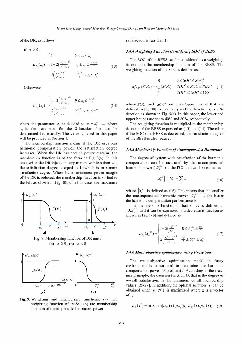
of the DR, as follows.
If 0ia ≥ ,
( )( )
2
2
2
2
1 0
( ) 1 2
2
mi i i i
mi
i i
m mi i i i
mi i
i i
x a a x
X i i ix a
x x a x m
i ix a
x a
x a x
x x
µ − +
−
− +
−
≤ ≤= − ≤ ≤ ≤ ≤
(13)
Otherwise,
( )
( )
2
2
2
2
1 2 0
( )
2
mi i i i
mi i
im m
i i i i
mi i
x a a x
ix a
X ix x a x m
i ix a
x
x
x x
µ
− +
−
− +
−
− ≤ ≤= ≤ ≤
(14)
where the parameter ia is decided as
m
i i ia x c= − where
ic is the parameter for the S-function that can be
determined heuristically. The value ic used in this paper
will be provided in Section 4.
The membership function means if the DR uses less
harmonic compensation power, the satisfaction degree
increases. When the DR has enough power margins, the
membership function is of the form as Fig. 8(a). In this
case, when the DR injects the apparent power less than ia ,
the satisfaction degree is equal to 1, which is maximum
satisfaction degree. When the instantaneous power margin
of the DR is reduced, the membership function is shifted to
the left as shown in Fig. 8(b). In this case, the maximum
satisfaction is less than 1.
3.4.4 Weighting Function Considering SOC of BESS The SOC of the BESS can be considered as a weighting
function to the membership function of the BESS. The
weighting function of the SOC is defined as
0 0
( ) ( )
1 100
l
l u
BAT
u
SOC SOC
wf SOC g SOC SOC SOC SOC
SOC SOC
≤ ≤
= ≤ ≤ ≤ ≤
(15)
where lSOC and uSOC are lower/upper bound that are
defined in [0,100], respectively and the function g is a S-
function as shown in Fig. 9(a). In this paper, the lower and
upper bounds are set to 40% and 80%, respectively.
The weighting function is multiplied to the membership
function of the BESS expressed as (13) and (14). Therefore,
if the SOC of a BESS is decreased, the satisfaction degree
of the BESS is also reduced.
3.4.5 Membership Function of Uncompensated Harmonics The degree of system-wide satisfaction of the harmonic
compensation can be measured by the uncompensated
harmonic power (obj
hS ) at the PCC that can be defined as
obj m
h h i
i
S S x= −∑ (16)
where
m
hS is defined as (16). This means that the smaller
the uncompensated harmonic power obj
hS is, the better
the harmonic compensation performance is.
The membership function of harmonics is defined in
[0, ]m
hS and it can be expressed in a decreasing function as
shown in Fig. 9(b) and defined as
( )
( )
2
2
2
2
1 2 0
( )
2
obj mh h
mh
hobj m m
hh h
mh
S Sobj
hSobj
S hS S S obj m
h hS
S
S
S S
µ−
− ≤ ≤
= ≤ ≤
(17)
3.4.6 Multi-objective optimization using Fuzzy Sets The multi-objective optimization model in fuzzy
environment is constructed to determine the harmonic
compensation power ( ix ) of unit i. According to the max-
min principle, the decision function D, that is the degree of
overall satisfaction, is the minimum of all membership
values [25-27]. In addition, the optimal solution *x can be
obtained when *( )
Dµ x is maximized where x is a vector
of xi.
1 2 3
*( ) max min[ ( ), ( ), ( ), ( )]
hD X X X Sµ µ µ µ µ=x
x x x x x (18)
m
ixia ix
( )iX ixµ
( )i if x
0
1
m
ixiaix
( )iX ixµ
( )i if x
0
1
ic ic
Fig. 8. Membership function of DR unit i:
(a) 0ia ≥ , (b) 0
ia <
0 lSOC
(%)SOC
( )g SOC
uSOC 100
1
( )BATwf SOC
0
( )h
obj
S hSµ
1
obj
hSm
hS
Fig. 9. Weighting and membership functions: (a) The
weighting function of BESS, (b) the membership
function of uncompensated harmonic power
Intelligent Coordination Method of Multiple Distributed Resources for Harmonic Current Compensation in a Microgrid
840
Then, the participation factors in the harmonic
compensation of the DRs can be obtained as
( )m
h
pfS
=*
* xx (19)
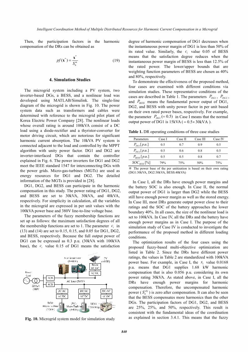
4. Simulation Studies
The microgrid system including a PV system, two
inverter-based DGs, a BESS, and a nonlinear load was
developed using MATLAB/Simulink. The single-line
diagram of the microgrid is shown in Fig. 10. The power
system data such as transformers and cables were
determined with reference to the microgrid pilot plant of
Korea Electric Power Company [28]. The nonlinear loads
whose overall rating is around 100kVA consist of a DC
load using a diode-rectifier and a thyristor-converter for
motor driving circuit, which are notorious for significant
harmonic current absorption. The 10kVA PV system is
connected adjacent to the load and controlled by the MPPT
algorithm with unity power factor. DG1 and DG2 are
inverter-interfaced DGs that contain the controller
explained in Fig. 6. The power inverters for DG1 and DG2
meet the IEEE standard 1547 for interconnecting DGs with
the power grids. Micro-gas-turbines (MGTs) are used as
energy resources for DG1 and DG2. The detailed
information of the MGTs is provided in [28].
DG1, DG2, and BESS can participate in the harmonic
compensation in this study. The power rating of DG1, DG2,
and BESS are set to 30kVA, 30kVA, and 40kVA,
respectively. For simplicity in calculation, all the variables
in the microgrid are expressed in per unit values with the
100kVA power base and 380V line-to-line voltage base.
The parameters of the fuzzy membership functions are
set up as follows: the maximum satisfaction degrees of all
the membership functions are set to 1. The parameter ic in
(13) and (14) are set to 0.15, 0.15, and 0.05 for DG1, DG2,
and BESS, respectively. Because the full output power of
DG1 can be expressed as 0.3 p.u. (30kVA with 100kVA
base), the ic value 0.15 of DG1 means the satisfaction
degree of harmonic compensation of DG1 decreases when
the instantaneous power margin of DG1 is less than 50% of
its rated value. Similarly, the ic value 0.05 of BESS
means that the satisfaction degree reduces when the
instantaneous power margin of BESS is less than 12.5% of
the rated power. The lower/upper bounds that are
weighting function parameters of BESS are chosen as 40%
and 80%, respectively.
To demonstrate the effectiveness of the proposed method,
four cases are examined with different conditions via
simulation studies. These representative conditions of the
cases are described in Table 1. The parameters 1DGP , 2DG
P ,
and BESSP means the fundamental power output of DG1,
DG2, and BESS with unity power factor in per unit based
on their own rated power bases, respectively. For example,
the parameter 1( 0.5)
DGP = in Case I means that the normal
output power of DG1 is 15kVA ( 0.5 30kVA= × ).
Table 1. DR operating conditions of three case studies
Parameters Case I Case II Case III Case IV
1[ . .]DGP p u 0.5 0.7 0.9 0.5
2 [ . .]DGP p u 0.5 0.6 0.8 0.5
[ . .]BESSP p u 0.5 0.5 0.8 0.7
[%]BESSSOC 79% 75% 50% 75%
※ The power base of the per unitization is based on their own rating
(DG1:30kVA, DG2:30kVA, BESS:40kVA)
In Case I, all the DRs have enough power margins and
the battery SOC is also enough. In Case II, the normal
output power of DG1 is larger than DG2 while the BESS
still have enough power margin as well as the stored energy.
In Case III, most DRs generate output power close to their
ratings and the SOC of the battery approaches the lower
boundary 40%. In all cases, the size of the nonlinear load is
set to 100kVA. In Case IV, all the DRs and the battery have
enough power margins as in Case I. The purpose of the
simulation study of Case IV is conducted to investigate the
performance of the proposed method in different loading
conditions.
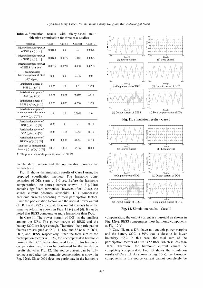
The optimization results of the four cases using the
proposed fuzzy-based multi-objective optimization are
listed in Table 2. Since the DRs have different power
ratings, the values in Table 2 are standardized with 100kVA
power base. For example, in Case I, the 1x value 0.0168
p.u. means that DG1 supplies 1.68 kW harmonic
compensation that is also 0.056 p.u. considering its own
power rating 30kVA. As stated above, in Case I, all the
DRs have enough power margins for harmonic
compensation. Therefore, the uncompensated harmonic
power (obj
hS ) is zero after compensation. It can also be seen
that the BESS compensates more harmonics than the other
DGs. The participation factors of DG1, DG2, and BESS
are 25%, 25%, and 50%, respectively. This result is
consistent with the fundamental ideas of the coordination
as explained in section 3.4.1. This means that the fuzzy
Fig. 10. Microgrid system model for simulation study
Hyun-Koo Kang, Choel-Hee Yoo, Il-Yop Chung, Dong-Jun Won and Seung-Il Moon
841
membership function and the optimization process are
well-defined.
Fig. 11 shows the simulation results of Case I using the
proposed coordination method. The harmonic com-
pensation of DRs starts at 1.0 sec. Before the harmonic
compensation, the source current shown in Fig. 11(a)
contains significant harmonics. However, after 1.0 sec, the
source current becomes sinusoidal. DRs compensate
harmonic currents according to their participation factors.
Since the participation factors and the normal power output
of DG1 and DG2 are equal, their output currents have the
same waveform as shown in Figs. 11 (c) and (d). It can be
noted that BESS compensates more harmonics than DGs.
In Case II, The power margin of DG1 is the smallest
among the DRs. The power margin of BESS and the
battery SOC are large enough. Therefore, the participation
factors are assigned as 0%, 11.16%, and 88.84% to DG1,
DG2, and BESS, respectively. Since the total sum of the
participation factors is 100%, the uncompensated harmonic
power at the PCC can be eliminated to zero. This harmonic
compensation results can be confirmed by the simulation
results shown in Fig. 12. The source current can be fully
compensated after the harmonic compensation as shown in
Fig. 12(a). Since DG1 does not participate in the harmonic
compensation, the output current is sinusoidal as shown in
Fig. 12(c). BESS compensates most harmonic components
as Fig. 12(e).
In Case III, most DRs have not enough power margins
and the battery SOC is 50% that is close to its lower
boundary 40%. In this case, the total sum of the
participation factors of DRs is 55.06%, which is less than
100%. Therefore, the harmonic current cannot be
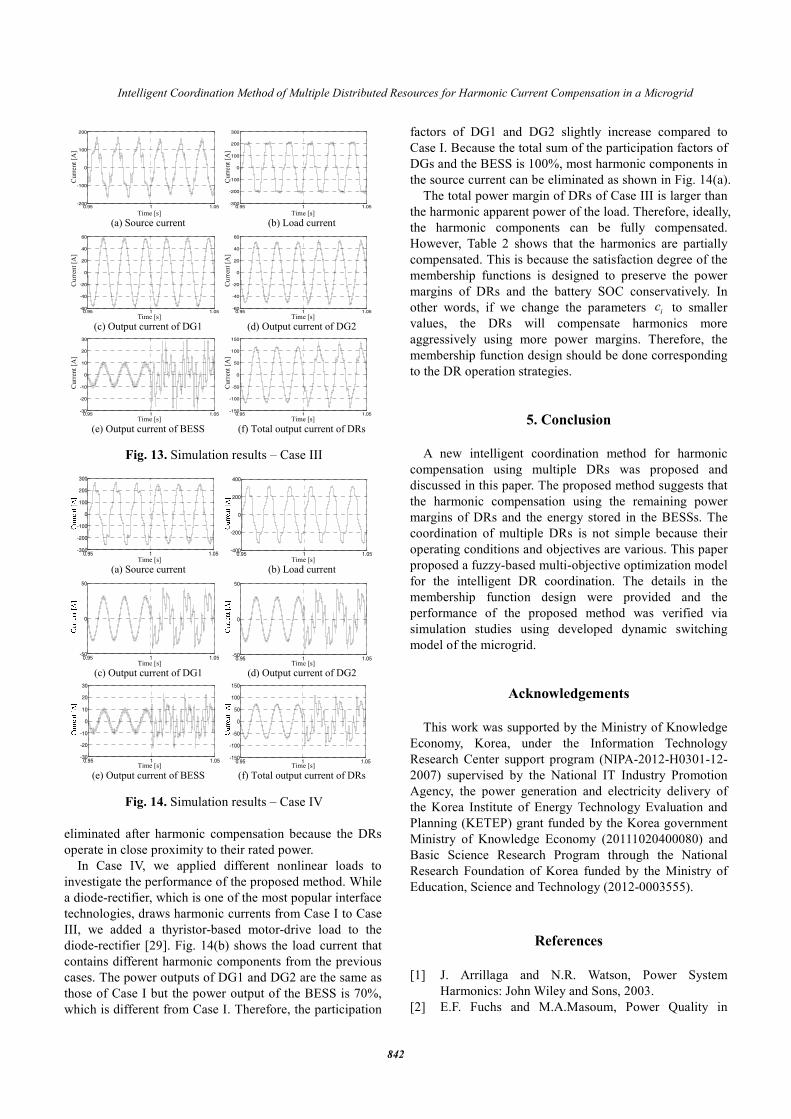
completely compensated. Fig. 13 shows the simulation
results of Case III. As shown in Fig. 13(a), the harmonic
components in the source current cannot completely be
Table 2. Simulation results with fuzzy-based multi-
objective optimization for three case studies
Variables Case I Case II Case III Case IV
Injected harmonic power
of DG1 (1x ) [p.u.]
0.0168 0.0 0.0 0.0375
Injected harmonic power
of DG2 (2x ) [p.u.]
0.0168 0.0075 0.0070 0.0375
Injected harmonic power
of BESS (3x ) [p.u.]
0.0336 0.0597 0.030 0.0233
Uncompensated
harmonic power at PCC
( obj
hS ) [p.u.]
0.0 0.0 0.0302 0.0
Satisfaction degree of
DG1 (1 1( )X xµ ) 0.975 1.0 1.0 0.875
Satisfaction degree of
DG2 (2 2( )X xµ ) 0.975 0.875 0.250 0.875
Satisfaction degree of
BESS (3 3( )Xwf xµ⋅ ) 0.975 0.875 0.250 0.875
Satisfaction degree of
uncompensated harmonic
power ( ( )h
obj
S hSµ ) 1.0 1.0 0.5961 1.0
Participation factor of
DG1 (1( )pf x ) [%]
25.0 0 0 38.15
Participation factor of
DG2 (2( )pf x ) [%]
25.0 11.16 10.42 38.15
Participation factor of
BESS (3( )pf x ) [%]
50.0 88.84 44.64 23.70
Total sum of participation
factors ( ( )kpf x∑ ) [%] 100.0 100.0 55.06 100.0
※ The power base of the per unitization is 100kVA.
0.95 1 1.05-200
-100
0
100
200
0.95 1 1.05-300
-200
-100
0
100
200
300
0.95 1 1.05-50
0
50
0.95 1 1.05-50
0
50
0.95 1 1.05-40
-20
0
20
40
0.95 1 1.05-150
-100
-50
0
50
100
150
(a) Source currentTime [s]
(b) Load currentTime [s]
(c) Output current of DG1Time [s]
(d) Output current of DG2Time [s]
(e) Output current of BESSTime [s]
(f) Total output current of DRsTime [s]
Fig. 11. Simulation results - Case I
(a) Source currentTime [s]
Curr
ent [A
]
(b) Load currentTime [s]
Curr
ent [A
]
(c) Output current of DG1Time [s]
Curr
ent [A
]
(d) Output current of DG2Time [s]
Curr
ent [A
]
(e) Output current of BESSTime [s]
Curr
ent [A
]
(f) Total output current of DRsTime [s]
Curr
ent [A
]
0.95 1 1.05-200
-100
0
100
200
0.95 1 1.05-300
-200
-100
0
100
200
300
0.95 1 1.05-60
-40
-20
0
20
40
60
0.95 1 1.05-60
-40
-20
0
20
40
60
0.95 1 1.05-60
-40
-20
0
20
40
60
0.95 1 1.05-200
-100
0
100
200
Fig. 12. Simulation results – Case II
Intelligent Coordination Method of Multiple Distributed Resources for Harmonic Current Compensation in a Microgrid
842
eliminated after harmonic compensation because the DRs
operate in close proximity to their rated power.
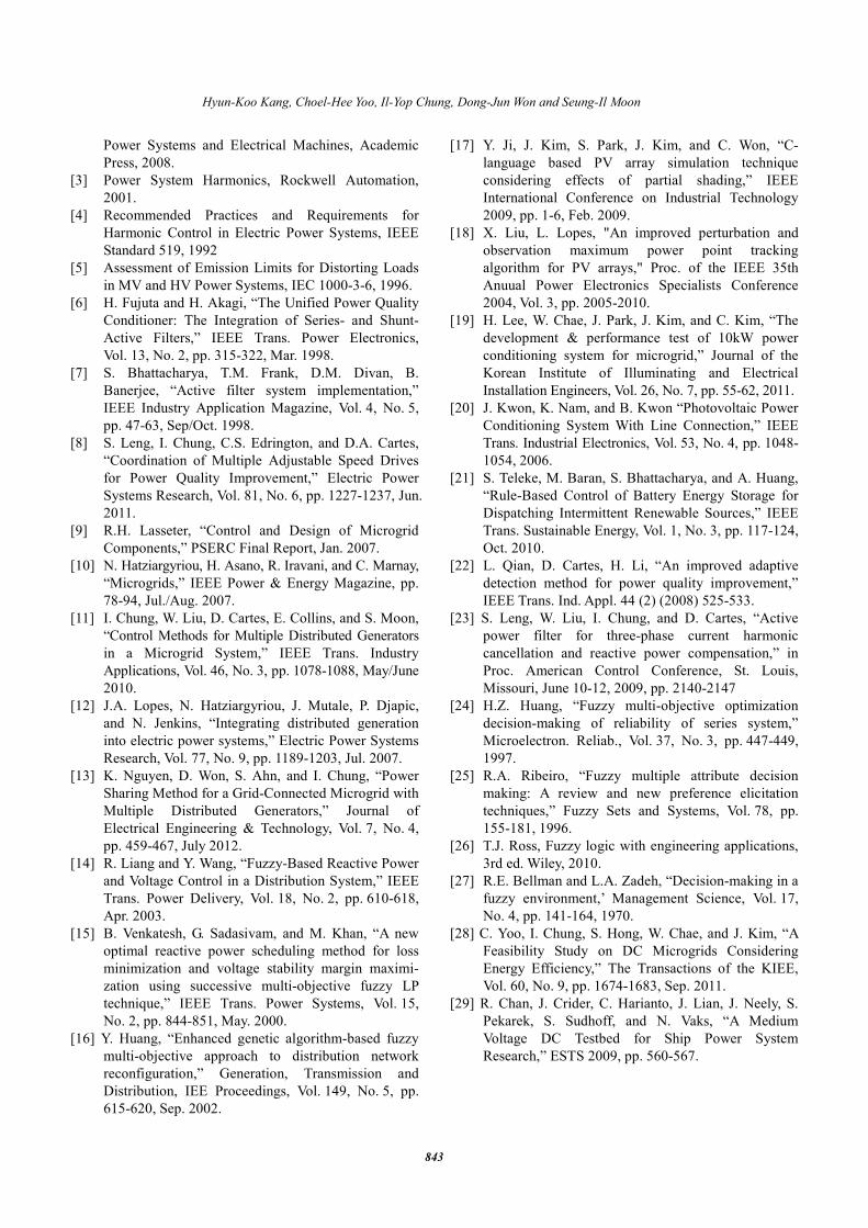
In Case IV, we applied different nonlinear loads to
investigate the performance of the proposed method. While
a diode-rectifier, which is one of the most popular interface
technologies, draws harmonic currents from Case I to Case
III, we added a thyristor-based motor-drive load to the
diode-rectifier [29]. Fig. 14(b) shows the load current that
contains different harmonic components from the previous
cases. The power outputs of DG1 and DG2 are the same as
those of Case I but the power output of the BESS is 70%,
which is different from Case I. Therefore, the participation
factors of DG1 and DG2 slightly increase compared to
Case I. Because the total sum of the participation factors of
DGs and the BESS is 100%, most harmonic components in
the source current can be eliminated as shown in Fig. 14(a).
The total power margin of DRs of Case III is larger than
the harmonic apparent power of the load. Therefore, ideally,
the harmonic components can be fully compensated.
However, Table 2 shows that the harmonics are partially
compensated. This is because the satisfaction degree of the
membership functions is designed to preserve the power
margins of DRs and the battery SOC conservatively. In
other words, if we change the parameters ic to smaller
values, the DRs will compensate harmonics more
aggressively using more power margins. Therefore, the
membership function design should be done corresponding
to the DR operation strategies.
5. Conclusion
A new intelligent coordination method for harmonic
compensation using multiple DRs was proposed and
discussed in this paper. The proposed method suggests that
the harmonic compensation using the remaining power
margins of DRs and the energy stored in the BESSs. The
coordination of multiple DRs is not simple because their
operating conditions and objectives are various. This paper
proposed a fuzzy-based multi-objective optimization model
for the intelligent DR coordination. The details in the
membership function design were provided and the
performance of the proposed method was verified via
simulation studies using developed dynamic switching
model of the microgrid.
Acknowledgements
This work was supported by the Ministry of Knowledge
Economy, Korea, under the Information Technology
Research Center support program (NIPA-2012-H0301-12-
2007) supervised by the National IT Industry Promotion
Agency, the power generation and electricity delivery of
the Korea Institute of Energy Technology Evaluation and
Planning (KETEP) grant funded by the Korea government
Ministry of Knowledge Economy (20111020400080) and
Basic Science Research Program through the National
Research Foundation of Korea funded by the Ministry of
Education, Science and Technology (2012-0003555).
References
[1] J. Arrillaga and N.R. Watson, Power System
Harmonics: John Wiley and Sons, 2003.
[2] E.F. Fuchs and M.A.Masoum, Power Quality in
0.95 1 1.05-300
-200
-100
0
100
200
300
0.95 1 1.05-200
-100
0
100
200
(a) Source currentTime [s]
Curr
ent [A
]
(b) Load currentTime [s]
Curr
ent [A
]
(c) Output current of DG1Time [s]
Curr
ent [A
]
(d) Output current of DG2Time [s]
Curr
ent [A
]
(e) Output current of BESSTime [s]
Curr
ent [A
]
(f) Total output current of DRsTime [s]
Curr
ent [A
]
0.95 1 1.05-60
-40
-20
0
20
40
60
0.95 1 1.05-60
-40
-20
0
20
40
60
0.95 1 1.05-30
-20
-10
0
10
20
30
0.95 1 1.05-150
-100
-50
0
50
100
150
Fig. 13. Simulation results – Case III
0.95 1 1.05-150
-100
-50
0
50
100
150
0.95 1 1.05-30
-20
-10
0
10
20
30
0.95 1 1.05-50
0
50
0.95 1 1.05-50
0
50
0.95 1 1.05-400
-200
0
200
400
0.95 1 1.05-300
-200
-100
0
100
200
300
(a) Source currentTime [s]
(b) Load currentTime [s]
(c) Output current of DG1Time [s]
(d) Output current of DG2Time [s]
(e) Output current of BESSTime [s]
(f) Total output current of DRsTime [s]
Fig. 14. Simulation results – Case IV
Hyun-Koo Kang, Choel-Hee Yoo, Il-Yop Chung, Dong-Jun Won and Seung-Il Moon
843
Power Systems and Electrical Machines, Academic
Press, 2008.
[3] Power System Harmonics, Rockwell Automation,
2001.
[4] Recommended Practices and Requirements for
Harmonic Control in Electric Power Systems, IEEE
Standard 519, 1992
[5] Assessment of Emission Limits for Distorting Loads
in MV and HV Power Systems, IEC 1000-3-6, 1996.
[6] H. Fujuta and H. Akagi, “The Unified Power Quality
Conditioner: The Integration of Series- and Shunt-
Active Filters,” IEEE Trans. Power Electronics,
Vol. 13, No. 2, pp. 315-322, Mar. 1998.
[7] S. Bhattacharya, T.M. Frank, D.M. Divan, B.
Banerjee, “Active filter system implementation,”
IEEE Industry Application Magazine, Vol. 4, No. 5,
pp. 47-63, Sep/Oct. 1998.
[8] S. Leng, I. Chung, C.S. Edrington, and D.A. Cartes,
“Coordination of Multiple Adjustable Speed Drives
for Power Quality Improvement,” Electric Power
Systems Research, Vol. 81, No. 6, pp. 1227-1237, Jun.
2011.
[9] R.H. Lasseter, “Control and Design of Microgrid
Components,” PSERC Final Report, Jan. 2007.
[10] N. Hatziargyriou, H. Asano, R. Iravani, and C. Marnay,
“Microgrids,” IEEE Power & Energy Magazine, pp.
78-94, Jul./Aug. 2007.
[11] I. Chung, W. Liu, D. Cartes, E. Collins, and S. Moon,
“Control Methods for Multiple Distributed Generators
in a Microgrid System,” IEEE Trans. Industry
Applications, Vol. 46, No. 3, pp. 1078-1088, May/June
2010.
[12] J.A. Lopes, N. Hatziargyriou, J. Mutale, P. Djapic,
and N. Jenkins, “Integrating distributed generation
into electric power systems,” Electric Power Systems
Research, Vol. 77, No. 9, pp. 1189-1203, Jul. 2007.
[13] K. Nguyen, D. Won, S. Ahn, and I. Chung, “Power
Sharing Method for a Grid-Connected Microgrid with
Multiple Distributed Generators,” Journal of
Electrical Engineering & Technology, Vol. 7, No. 4,
pp. 459-467, July 2012.
[14] R. Liang and Y. Wang, “Fuzzy-Based Reactive Power
and Voltage Control in a Distribution System,” IEEE
Trans. Power Delivery, Vol. 18, No. 2, pp. 610-618,
Apr. 2003.
[15] B. Venkatesh, G. Sadasivam, and M. Khan, “A new
optimal reactive power scheduling method for loss
minimization and voltage stability margin maximi-
zation using successive multi-objective fuzzy LP
technique,” IEEE Trans. Power Systems, Vol. 15,
No. 2, pp. 844-851, May. 2000.
[16] Y. Huang, “Enhanced genetic algorithm-based fuzzy
multi-objective approach to distribution network
reconfiguration,” Generation, Transmission and
Distribution, IEE Proceedings, Vol. 149, No. 5, pp.
615-620, Sep. 2002.
[17] Y. Ji, J. Kim, S. Park, J. Kim, and C. Won, “C-
language based PV array simulation technique
considering effects of partial shading,” IEEE
International Conference on Industrial Technology
2009, pp. 1-6, Feb. 2009.
[18] X. Liu, L. Lopes, "An improved perturbation and
observation maximum power point tracking
algorithm for PV arrays," Proc. of the IEEE 35th
Anuual Power Electronics Specialists Conference
2004, Vol. 3, pp. 2005-2010.
[19] H. Lee, W. Chae, J. Park, J. Kim, and C. Kim, “The
development & performance test of 10kW power
conditioning system for microgrid,” Journal of the
Korean Institute of Illuminating and Electrical
Installation Engineers, Vol. 26, No. 7, pp. 55-62, 2011.
[20] J. Kwon, K. Nam, and B. Kwon “Photovoltaic Power
Conditioning System With Line Connection,” IEEE
Trans. Industrial Electronics, Vol. 53, No. 4, pp. 1048-
1054, 2006.
[21] S. Teleke, M. Baran, S. Bhattacharya, and A. Huang,
“Rule-Based Control of Battery Energy Storage for
Dispatching Intermittent Renewable Sources,” IEEE
Trans. Sustainable Energy, Vol. 1, No. 3, pp. 117-124,
Oct. 2010.
[22] L. Qian, D. Cartes, H. Li, “An improved adaptive
detection method for power quality improvement,”
IEEE Trans. Ind. Appl. 44 (2) (2008) 525-533.
[23] S. Leng, W. Liu, I. Chung, and D. Cartes, “Active
power filter for three-phase current harmonic
cancellation and reactive power compensation,” in
Proc. American Control Conference, St. Louis,
Missouri, June 10-12, 2009, pp. 2140-2147
[24] H.Z. Huang, “Fuzzy multi-objective optimization
decision-making of reliability of series system,”
Microelectron. Reliab., Vol. 37, No. 3, pp. 447-449,
1997.
[25] R.A. Ribeiro, “Fuzzy multiple attribute decision
making: A review and new preference elicitation
techniques,” Fuzzy Sets and Systems, Vol. 78, pp.
155-181, 1996.
[26] T.J. Ross, Fuzzy logic with engineering applications,
3rd ed. Wiley, 2010.
[27] R.E. Bellman and L.A. Zadeh, “Decision-making in a
fuzzy environment,’ Management Science, Vol. 17,
No. 4, pp. 141-164, 1970.
[28] C. Yoo, I. Chung, S. Hong, W. Chae, and J. Kim, “A
Feasibility Study on DC Microgrids Considering
Energy Efficiency,” The Transactions of the KIEE,
Vol. 60, No. 9, pp. 1674-1683, Sep. 2011.
[29] R. Chan, J. Crider, C. Harianto, J. Lian, J. Neely, S.
Pekarek, S. Sudhoff, and N. Vaks, “A Medium
Voltage DC Testbed for Ship Power System
Research,” ESTS 2009, pp. 560-567.
Intelligent Coordination Method of Multiple Distributed Resources for Harmonic Current Compensation in a Microgrid
844
Hyun-Koo Kang received his B.S. and
M.S. degrees in electrical engineering
from Seoul National University, Seoul,
Korea, in 2005 and 2007, respectively,
where he is currently pursuing the Ph.D.
degree. His research interests are
power quality, distributed energy
resources, and operation of microgrid.
Cheol-Hee Yoo received the B.S. and
M.S. degrees in electronics engineering
from Kookmin University, Seoul,
Korea, in 2007 and 2009, respectively,
where he is currently working toward
his Ph.D. degree. His research interests
are in the areas of microgrids,
renewable energy applications,
hardware-in-the-loop simulation, multi-agent system, and
high-efficiency power converters.
Il-Yop Chung received his B.S., M.S.,
and Ph.D. degrees in electrical
engineering from Seoul National
University, Seoul, Korea, in 1999,
2001, and 2005, respectively. He was a
Postdoctoral Associate at Virginia Tech,
Blacksburg, VA, from 2005 to 2007.
From 2007 to 2010, he worked for the
Center for Advanced Power Systems at Florida State
University, Tallahassee, FL as an Assistant Scholar
Scientist. Currently, he is an Assistant Professor at
Kookmin University, Seoul, Korea. His research interests
are power quality, distributed energy resources, renewable
energy, and shipboard power systems.
Dong-Jun Won received B.S., M.S.,
and Ph.D. degrees in Electrical Engi-
neering, Seoul National University,
Seoul, Korea in 1998, 2000, and 2004
respectively. He was a Postdoctoral
Fellow with the APT Center, Uni-
versity of Washington, Seattle, WA,
USA. Currently, he is an Associate
Professor with the School of Electrical
Engineering, INHA University, Incheon, Korea. His
research interests include power quality, microgrid,
renewable energy, and smart grid.
Seung-Il Moon received the B.S.
degree in electrical engineering from
Seoul National University, Seoul,
Korea, in 1985, and the M.S. and
Ph.D. degrees in Electrical Engi-
neering from Ohio State University,
Columbus, OH, USA in 1989 and
1993, respectively. Currently, he is a
Professor of the School of Electrical Engineering and
Computer Science at Seoul National University. He is the
Editor-in-Chief of Journal of Electrical Engineering and
Technology and also the Vice Chairman of Editorial Board
of the Korean Institute of Electrical Engineers (KIEE)
since 2008. His special fields of interest include power
quality, flexible ac transmission system, renewable energy,
and distributed generation.