
Operations Management Facility Visit Report Operations Management – Mahou
Upload
khangminh22Category
view
2download
0
UNIVERSITY OF CALIFORNIA
Los Angeles
Integration of Sorption Enhanced Operations into Sustainable Processes
A dissertation submitted in partial satisfaction of the
requirements for the degree of Doctor of Philosophy
in Chemical Engineering
by
Abdulaziz Ali Alturki
2020


ii
ABSTRACT OF THE DISSERTATION
Integration of Sorption Enhanced Operations into Sustainable Processes
by
Abdulaziz Ali Alturki
Doctor of Philosophy in Chemical Engineering
University of California, Los Angeles, 2020
Professor Dante A. Simonetti, Chair
Stabilizing atmospheric concentrations of CO2 has become a significant focus worldwide
as environmental concern continues to increase and carbon-based fuel sources continue to play a
significant role in energy generation. For this reason, mitigation actions are needed to stabilize the
atmospheric CO2 concentration at 500 parts per million. The International Energy Agency has
suggested the use of carbon-neutral renewable energy sources such as biomass, carbon-free
sources such as hydrogen, and carbon capture and storage as effective CO2 reduction methods.
These technologies have the potential to reduce anthropogenic CO2 during the transition towards
a low-carbon energy system. This study focused on discovering a combination of these approaches
that uses innovative sorption processes to achieve lower overall carbon emissions. The objectives
of this work were to study the fundamental structure–function relationships for organic and
inorganic synthetic materials in sorption application systems and analyze the common
characteristics shared between adsorption, absorption, and ion exchange for the extraction of
molecules and ions from aqueous solutions. The research also investigated applying sorption

iii
operations in sustainable processes to improve efficiency, reduce energy, and subsequently, reduce
costs through process intensification by inducing reactions simultaneously with separation. The
merit of this process is attributed to efficient energy and material utilization.

iv
The dissertation of Abdulaziz Ali Alturki is approved.
Panagiotis D. Christofides
Vasilios Manousiouthakis
Louis Bouchard
Dante A. Simonetti, Committee Chair
University of California, Los Angeles
2020

v
Table of Contents
Chapter 1: Introduction ................................................................................................................... 1
1.1 Motivation ................................................................................................................................. 1
1.2 Introduction and Methodology ................................................................................................. 2
1.3 Research Objectives .................................................................................................................. 7
1.4 References ............................................................................................................................... 11
Chapter 2: Oxygenate Adsorption onto Hydrophilic Zeolites from Aqueous Solution................ 17
2.1 Abstract ................................................................................................................................... 17
2.2 Introduction ............................................................................................................................. 18
2.3 Experimental Methods ............................................................................................................ 20
2.3.1 Materials ............................................................................................................................20
2.3.2 Batch Adsorption Equilibria Tests ....................................................................................20
2.3.3 Adsorption Modeling ........................................................................................................21
2.3.3.1 Langmuir Isotherm .....................................................................................................21
2.3.3.2 Langmuir Multicomponent Isotherm .........................................................................24
2.3.3.3 Freundlich Isotherm ...................................................................................................24
2.3.3.4 Freundlich Multicomponent Isotherm ........................................................................25
2.4 Results ......................................................................................................................................27
2.4.1 Adsorption Equilibrium Data ............................................................................................27
2.5 Discussion ................................................................................................................................34
2.5.1 Isotherm Modeling Results ...............................................................................................34
2.5.2 Langmuir Model ................................................................................................................34
2.5.3 Freundlich Adsorption Isotherm .......................................................................................38
2.6 Conclusion ...............................................................................................................................39
2.7 Appendix ..................................................................................................................................41
2.8 References ................................................................................................................................44
Chapter 3: Efficient Hydrogen Production from N-butanol Steam Reforming Obtained from ABE Fermentation Using RD ........................................................................................................48
3.1 Abstract ....................................................................................................................................48
3.2 Introduction ..............................................................................................................................49

vi
3.3 Process Description ..................................................................................................................54
3.3.1 Baseline .............................................................................................................................54
3.3.1.1 Adsorption Process .....................................................................................................54
3.3.1.2 Steam Reforming Process ...........................................................................................55
3.4 Modeling Methodology ...........................................................................................................58
3.4.1 Aspen Plus Flowsheet .......................................................................................................58
3.4.2 Minimization of Gibbs Free Energy..................................................................................58
3.4.3 N-Butanol Reforming ........................................................................................................59
3.5 Experimental Methods .............................................................................................................63
3.5.1 Materials ............................................................................................................................63
3.5.2 Batch Adsorption Equilibria Tests ....................................................................................63
3.6 Results and Discussion ............................................................................................................64
3.6.1 Adsorption Capacities .......................................................................................................64
3.6.2 Steam Reforming...............................................................................................................66
3.6.2.1 Baseline ......................................................................................................................66
3.6.3 Proposed RDSBR ..............................................................................................................75
3.7 Conclusion ...............................................................................................................................78
3.8 Appendix ..................................................................................................................................79
3.9 References ................................................................................................................................83
Chapter 4: Sensitivity Analysis of an Intensified CO2 Mineralization-based Scheme and RO Desalination Process in Ca2+/Mg2+-Rich Aqueous Solutions for CO2 Management .....................89
4.1 Abstract ....................................................................................................................................89
4.2 Introduction ..............................................................................................................................90
4.3 Process Modeling and Simulation ...........................................................................................93
4.3.1 Overall Description ...........................................................................................................93
4.3.2 Thermodynamic Framework .............................................................................................94
4.3.2.1 CO2 Amine-Capture Unit ...........................................................................................94
4.3.2.2 CO2 Absorption Using Alkaline .................................................................................95
4.4 Results and Discussion ............................................................................................................96
4.4.1 Base Case ..........................................................................................................................96
4.4.1.1 CO2 Capture and Sequestration ..................................................................................96
4.4.1.2 CO2 Desorption via Electrolysis .................................................................................99
4.4.1.3 CO2 Mineralization ...................................................................................................102

vii
4.4.2 Advanced Cases ..............................................................................................................109
4.4.2.1 Reducing Power Consumption Below Baseline .......................................................109
4.4.2.2 Integration Approach ................................................................................................114
4.4.2.3 Energy Advantage ....................................................................................................116
4.5 Conclusion .............................................................................................................................119
4.6 References ..............................................................................................................................120
Chapter 5: Application of Ion-Exchange Processes for CO2 Mineralization ..............................128
5.1 Abstract ..................................................................................................................................128
5.2 Introduction ............................................................................................................................129
5.3 Experimental Procedure .........................................................................................................132
5.3.1 Materials ..........................................................................................................................132
5.3.2 Experiments .....................................................................................................................133
5.3.2.1 Batch Experiments ....................................................................................................133
5.3.2.2 Dynamic Experiments with Ion-Exchange Column .................................................135
5.3.3 Solution Phase Analysis ..................................................................................................136
5.3.4 Modeling .........................................................................................................................137
5.3.4.1 Kinetic Sorption Modeling for Fixed-Bed Experiments ..........................................138
5.3.4.2 Kinetic Sorption Modeling for Batch Experiments ..................................................142
5.4 Results and Discussion ..........................................................................................................144
5.4.1 Selection of Ion-Exchange Materials ..............................................................................144
5.4.2 Ion-Exchange Selectivity ................................................................................................151
5.4.3 Batch Kinetic Results ......................................................................................................153
5.4.4 Polyvalent Ion-Exchange Kinetics ..................................................................................158
5.4.5 Column Experiments .......................................................................................................162
5.5 Conclusion .............................................................................................................................166
5.6 References ..............................................................................................................................167
Chapter 6: Application of Process Reactor Design Using CO2 Mineralization to Enhance Methane Reforming Process and Produce Carbon-free H2 ..........................................................177
6.1 Abstract ..................................................................................................................................177
6.2. Introduction ...........................................................................................................................178
6.3 Materials and Methods ...........................................................................................................183
6.3.1 Experimental Solutions ...................................................................................................183

viii
6.3.2 Characterization of Ion-Exchange Materials...................................................................183
6.3.3 Batch Equilibrium Experiments ......................................................................................184
6.3.4 Thermodynamic Modeling ..............................................................................................184
6.4 Process Description and Results ............................................................................................185
6.4.1 Steam Methane Reforming (SMR) .................................................................................185
6.4.2 Effect of Removing CO2 from SMR outlet .....................................................................188
6.4.3 The Use of Exothermic Carbonation Energy for Reforming ..........................................191
6.4.4 Sorption-Enhanced Steam Reforming by NaOH ............................................................193
6.4.5 Ion-Exchange-Enhanced Steam Reformer ......................................................................196
6.5 Discussion ..............................................................................................................................200
6.6 Conclusion .............................................................................................................................202
6.7 References ..............................................................................................................................204
Chapter 7: Techno-Economic Analysis of a Process to Convert Methane to Olefins Featuring a Combined Reformer Through the Methanol Intermediate ..........................................................210
7.1 Abstract ..................................................................................................................................210
7.2 Introduction ............................................................................................................................211
7.3 Approach and Modeling ........................................................................................................216
7.3.1 Design Basis and Assumptions .......................................................................................216
7.4 Process Description ................................................................................................................217
7.4.1 Catalytic Conversion .......................................................................................................218
7.5. Results and Discussion .........................................................................................................226
7.5.1 Thermodynamic Trends ..................................................................................................226
7.5.2 Material and Energy Balances.........................................................................................240
7.5.3 Economic Evaluation ......................................................................................................243
7.5.4 Energy Integration ...........................................................................................................245
7.5.5 Environmental Impact .....................................................................................................250
7.6 Conclusion .............................................................................................................................251
7.7 References ..............................................................................................................................252

ix
List of Figures Chapter 1 Figure 1.1. Using mineral carbonation technology to sequester CO2 from medium size emitters by chemically reacting CO2 with sodium-, calcium-, and magnesium-containing materials to form stable carbonates. ............................................................................................................................ 4 Figure 1.2. Biomass energy cycle of using adsorptive zeolitic materials and the integration potential of these materials during the desorption step. .................................................................. 5 Figure 1.3. Representation of the sustainable energy system. ........................................................ 7 Chapter 2
Figure 2.1. Equilibrium adsorption isotherms for single-component alcohols in aqueous solution for methanol (■ light blue), ethanol (● red), n-propanol (▲ light green), and n-butanol (▼ dark blue). ............................................................................................................................................. 28 Figure 2.2. Equilibrium adsorption isotherms for single-component aldehydes and ketones in aqueous solution for n-butyraldehyde (▼ grey), n-propionaldehyde (▼ light blue), and propanone (▼orange). .................................................................................................................................... 31 Figure 2.3. Equilibrium adsorption isotherms for multicomponent alcohols in aqueous solution for methanol (■ light blue), ethanol (● red), n-propanol (▲ light green), n-butanol (▼ dark blue), and 2-butanol (▼light blue). ............................................................................................................... 33 Figure 2.4. Equilibrium adsorption isotherms for multicomponent alcohols, aldehydes, and ketones in aqueous solution for methanol (■ light blue), ethanol (● red), n-propanol (▲ light green), n-butanol (▼ dark blue), n-butyraldehyde (▼ grey), and n-propionaldehyde (▼ light blue). ....... 34 Figure 2.5. Model isotherms for single-component alcohols in aqueous solution for methanol (■ light blue), ethanol (● red), n-propanol (▲ light green), n-butanol (▼ dark blue). The symbols show experimental values, and the solid and dashed lines show the Langmuir and Freundlich model results, respectively. ........................................................................................................... 35 Figure 2.6. Model isotherms for single-component aldehydes and ketones in aqueous solution for n-butyraldehyde (▼ grey), n-propionaldehyde (▼ light blue), and propanone (▼ orange). The symbols show experimental values, and the solid and dashed lines show the Langmuir and Freundlich model results, respectively. ........................................................................................ 36 Figure 2.7. The number of charge-balancing cations for each zeolite type for (a) the comparison of n-butanol and n-propanol adsorption over FER, MFI, and BEA and (b) n-butanol adsorption with FAU with Si/Al ratios of 2.6, 15 and 80. .............................................................................. 36 Figure 2.8. Competitive adsorption coefficients for methanol, ethanol, n-propanol, n-propionaldehyde, n-butyraldehyde, and 2-butanol with n-butanol for (a) BEA and (b) MFI. ..... 39 Chapter 3
Figure 3.1. Simplified flow diagram of the adsorption process. ................................................... 55 Figure 3.2. Simplified flow diagram of H2 production from the n-butanol steam reforming process........................................................................................................................................................ 56 Figure 3.3. Simplified flow diagram of the integrated approach; the combined desorber–reactor system operation includes a desorption outlet feed to the steam reforming reactor. .................... 57 Figure 3.4. Aspen Plus flowsheet of the n-butanol steam reformer. ............................................. 58 Figure 3.5. Equilibrium adsorption isotherms for single-component and multicomponent alcohols in aqueous solution for methanol (■ light blue), ethanol (● red), n-propanol (▲ light green), and n-butanol (▼ dark blue). ............................................................................................................... 66
x
Figure 3.6. Effects of temperature and steam-to-n-butanol (H2O/C4H9OH) molar ratio on the dry basis molar concentration flow rate of (a) H2 and H2O conversion, (b) H2 and CO, (c) CO2 and CH4, and (d) H2, CH4, and CO product selectivities. .................................................................... 69 Figure 3.7. Influence of the reformer operating temperature and steam-to-n-butanol ratio on (a) hydrogen production and (b) total energy consumption by the process to obtain hydrogen yield in (a). ................................................................................................................................................. 70 Figure 3.8. Heat exchanger network design of the n-butanol reformer. ....................................... 71 Figure 3.9. Heat exchanger network for (a) the baseline and (b) integrated approach showing the temperature−enthalpy change diagram. ........................................................................................ 72 Figure 3.10. Integrated heat exchanger system. ............................................................................ 72 Figure 3.11. Influence of the reformer operating temperature and steam-to-n-butanol ratio on the (a) hydrogen production and (b) total energy consumption by the process to obtain hydrogen yield in (a). ............................................................................................................................................. 73 Figure 3.12. Effect of temperature on the reformer product proportions of H2, CH4, CO, H2O, and CO2. The shaded regions represent the molar hydrogen, carbon monoxide, carbon dioxide, and methane conversion from n-butanol and the unreacted steam. ..................................................... 74 Figure 3.13. Effect of temperature on the thermal efficiency of the process (thermal efficiency is based on the approach developed by He and collaborators). ........................................................ 75 Figure 3.14. Specific power requirements for the n-butanol reforming process are divided into components (the orange color represents the cooling requirement, dark blue represents n-butanol feed heating, and dark red represents the reformer energy required to keep the temperature constant at 800 °C). ..................................................................................................................................... 77 Chapter 4
Figure 4.1. Process flow diagram of the amine unit flue gas being fed to the absorber and contacted with a lean solvent, removing 90 wt % of the CO2 from flue gas. The rich solvent is heated by incoming lean amine in a heat exchanger (HEX). ........................................................................ 98 Figure 4.2. CO2 absorption isotherm for (b) tertiary amine (MDEA) compared with (a) conventional absorbent (MEA). Amine/CO2 ratio (x-axis) is based on the inlet streams of flue gas and lean amine entering the absorber. Blue line represents the concentration of CO2 in the stream leaving the absorber, and square dotted lines represent the rich amine pH solution (□ red), MEACOO− (■ grey), and HCO3
− (■ dark red) leaving the absorber. ........................................... 99 Figure 4.3. Process flow diagram of the amine unit flue gas being fed to the absorber and contacted with a lean solvent, removing the CO2 from flue gas. The rich solvent is treated by being mixed with HCl solution generated from BPMED process followed by a treatment by NAOH generated from the same BPMED process. ................................................................................................. 100 Figure 4.4 (a) the amount of CO2 stripped (flash stream) from an amine solution for every additional mole of H+ added. Data shows that CO2 concentration in the flash stream increases with the addition of H+. Increasing H+ decreases the pH of amine from 8.5 to 7.25, and MEACOO- concentration decreases in a similar trend to pH. (b) addition of OH- through NaOH to rich-amine-+ to convert back to rich-amine. .................................................................................................. 101 Figure 4.5. Process flow diagram of continuous aqueous carbonation on Ca-containing solution with carbonation reactor and absorption. Flue gas is contacted with a lean alkali metal hydroxide–based solution in all cases; (a) using NaOH hydroxide, (b) using Ca-Mg(OH)2 hydroxide, and (c) using NH3 to remove 90 wt % of the CO2 from flue gas. In the carbonation reactor, the processes of coagulation and flocculation occur, resulting in the precipitation of CaCO3 and MgCO3. .... 103

xi
Figure 4.6. Aspen Plus simulation of fixed CO2 at 1 mol/h shows changes of outlet CO2 composition, pH (□ red), and other dissociations. MEACOO− (■ grey) and HCO3
− (■ dark red) with (a) varying NaOH:CO2 flow rates, (b) varying Ca(OH)2:CO2 flow rates, and (c) varying NH3:CO2 flow rates..................................................................................................................... 105 Figure 4.7. Heatmap of (a) pH changes and (b) calcium carbonate precipitation formation in aqueous solution leaving the absorber when changing the inlet concentrations of CaCl2 and NaOH with 1 mole of CO2 initially in the coming flue gas. .................................................................. 107 Figure 4.8. Heatmap of energy demand as a function of CaCl2 concentration in the inlet CO2 mineralization plant and produced mixture of Ca-MgCO3:NaHCO3 using Chlor-alkali process energy demand for NaOH generation.50 ..................................................................................... 108 Figure 4.9. Energy requirements for CO2 sequestration by (a) capture and injection in geologic formations (red and grey) and (b) baseline concept for carbon dioxide mineralization and disposal. Through NaOH generation by the Chlor-alkali process, this route entails two possible subroutes for CO2 converted products, NaHCO3 and CaCO3. The theoretical energy requirement for NaOH generation from NaCl has been shown to indicate the minimum energy needed. ...................... 109 Figure 4.10. Specific energy required to treat different sources of wastewater (seawater and brackish water) broken down into components (red for pretreatment process prior to RO and green for the RO process energy requirements). .................................................................................. 111 Figure 4.11. Effect of adding NaOH (bottom x-axis) to a concentrated brine composition (Ca, Mg) to adjust pH (left y-axis) that is in contact with flue gas at 45 kg/h to calculate carbonate precipitation. Effluent speciation (right y-axis) shows the reduction in Mg2+ (■ grey) and Ca2+ (■ black) for the solution as they form carbonates. Top x-axis shows the energy used and correlated to NaOH is added to solution. ..................................................................................................... 113 Figure 4.12. Effect of NaOH mass flow rate (bottom x-axis) to the carbonate products proportions of MgCO3 (red region), MgCO3·3H2O (orange region), CaCO3 (blue region), and NaHCO3 (green region). The change in CO2 flue gas concentration for the stream leaving the absorber is shown in the blue line; at 7 kg/h NaOH, CO2 is completely removed. ...................................................... 115 Figure 4.13. Effect of NaOH mass flow rate (bottom x-axis) to the carbonate products proportions of MgCO3 (red region), MgCO3·3H2O (orange region), CaCO3 (blue region), and NaHCO3 (green region). The change in CO2 flue gas concentration for the stream leaving the absorber is shown in the blue line; at 20 kg/h NaOH, CO2 is completely removed. .................................................... 116 Figure 4.14. Specific energy requirement to treat different sources of wastewater broken down into components (red for pretreatment process prior to RO and green for the RO process energy requirements) compared with energy required to treat the same wastewater sources through CO2 mineralization approach. Dotted rectangle shape shows the integration potential to reduce energy required to treat water (kWh/m3) by combined CO2 mineralization and RO plants. ................. 118 Chapter 5
Figure 5.1. Process flow diagram of ion-exchange setup for precipitation experiments. Flue gas is contacted with a either fresh water or ca-containing solution. ................................................... 136 Figure 5.2. Effect of material solid loading on the pH of materials. .......................................... 145 Figure 5.3. Aminomethylphosphonic acid chelating groups that occur (drawing made using MarvinSketch)............................................................................................................................. 147 Figure 5.4. Iminodiacetate groups that occur in Lewatit TP 207 (drawing made using MarvinSketch)............................................................................................................................. 147 Figure 5.5. Effect of solid loading on the pH of solution at various initial concentrations. ....... 149 Figure 5.6. Cation exchange capacity of various concentrations of materials............................ 149

xii
Figure 5.7. H+ uptake reduction as a function of equilibrium calcium concentrations increasing in solution in (a) HCl and (b) saturated CO2 solution. .................................................................... 152 Figure 5.8. Na+ release and exchange with H+ from solution as functions of time for TP207, TP260, 4A, and 13X undergoing ion exchange under static and convective (stirred) mixing conditions for an initial CO2 concentration of 34 mmol/L................................................................................. 157 Figure 5.9. Na+ exchanged by Ca2+ concentrations as functions of time for TP207, TP260, 4A, and 13X undergoing ion exchange under static conditions. .............................................................. 160 Figure 5.10. Na+ exchanged by Mg2+ concentrations as functions of time for TP207, TP260, 4A, and 13X undergoing ion exchange under static conditions. ....................................................... 160 Figure 5.11. Na+ exchanged by Fe3+ concentrations as functions of time for TP207, TP260, 4A, and 13X undergoing ion exchange under static conditions. ....................................................... 161 Figure 5.12. Breakthrough curves for the alkalinity-inducing reaction at different flow rates for (a) R-1 (TP 207), (b) R-2 (TP 260), (c) Z-1 (Zeolite 4A), and (d) Z-2 (Zeolite 13X). Dashed lines represent Bohart–Adams model predictions for breakthrough curves. ...................................... 164 Chapter 6 Figure 6.1. The conventional process of precipitated calcium carbonate production. ............... 182 Figure 6.2. The effect of temperature on the H2 yield product of the SMR. .............................. 187 Figure 6.3. The effect of pressure on the SMR product proportions of H2, CH4, CO and H2O. 188 Figure 6.4. The process flow diagamr of SESR showing the varies reforming sorption stages of the process. .................................................................................................................................. 189 Figure 6.5. Effect of temperature on the H2 yield product of the SESR ..................................... 190 Figure 6.6. Aspen Plus flowsheet depicting each stage reactor “REF” represents the reformer and six reactors .................................................................................................................................. 192 Figure 6.7. Process diagram for the proposed process of the carbonation of produced water using NaOH absorption to continuously remove CO2. Three reactors, namely (1) a reformer and WGS reactor, (2) an absorber, and (3) a precipitation reactor, are shown. .......................................... 195 Figure 6.8. Calcium carbonation precipitation as a function of NaOH addition. ....................... 195 Figure 6.9. Process diagram for the proposed process of the carbonation of produced water using ion-exchange. Three reactors, namely (1) a reformer and WGS reactor, (2) an ion-exchange reactor, and (3) a precipitation reactor, are shown. ..................................................................... 198 Figure 6.10. Equilibrium isotherms for CO2 solutions developed using saturated CO2 (pH 3.9, 100% CO2), pH 4.5, and pH 5.3. ................................................................................................ 198 Figure 6.11. Ion-exchange reactions for different materials over time from 5 °C to 50 °C under static conditions. ......................................................................................................................... 199 Figure 6. 12. Process Flow diagram showing the effect of temperature on the H2 yield product of the SESR with the continuous removal of H2 from outlet .......................................................... 202 Figure 6.13. The effect of temperature on the H2 yield product of the SESR with the continuous removal of H2 from outlet. .......................................................................................................... 202 Chapter 7
Figure 7.1 MTO flowsheet using SMR, DRM, and POX reforming technologies. ................... 218 Figure 7.2. Effect of CH4:H2O ratio on conversion, syngas yield, CO2 and H2O generation, energy input, and carbon deposition in SMR (P = 1 bar). ...................................................................... 228 Figure 7.3. Effects of CH4:O2 ratio on conversion, syngas yield waste production, energy input, and carbon deposition in POX (P = 1 bar). ................................................................................. 229 Figure 7.4. Effects of CH4:CO2 ratio on conversion, syngas yield, CO2 generation, and carbon deposition in DRM (P = 1 bar). .................................................................................................. 231

xiii
Figure 7.5. Effects of CH4:O2 ratio on conversion, syngas yield waste production, energy input, and carbon deposition in POX (P = 1 bar). ................................................................................. 233 Figure 7.6. Effects of CH4:O2 ratio on conversion, syngas yield, energy input, and carbon deposition in POX (P = 1 bar). ................................................................................................... 236 Figure 7.7. (a) Effects of varying the CO:CO2 ratio with fixed H2 (nH2 = 2 mol) feed on the conversion of syngas to produce methanol at 373 K and 10 bar (b) effect if varying both CO and H2 in the reactor feed without CO2 as a co-feed at 373 K and 10 bar; (c) the same outlet composition obtained from the CR was used as a feed for methanol reactor.................................................. 239 Figure 7.8. Energy input for syngas production from various routes: (a) DRM, (b) SMR, (c) (POX), and (d) CR. .................................................................................................................................. 242 Figure 7.9. Energy input for ethane steam cracking. .................................................................. 242 Figure 7.10. Proposed methane-to-olefin design process flow sheet.......................................... 243 Figure 7.11. Temperature−enthalpy change diagram for (a) the baseline and (b) integrated approaches and (c) the grand composite curve for heat integration of the methane-to-olefin plant...................................................................................................................................................... 248 Figure 7.12. Heat exchanger network (HEN) diagram obtained using ASPEN Energy Analyzer, where red lines show hot streams and blue lines show cold streams for (a) the baseline and (b) the proposed heat integration network. ............................................................................................. 249 Figure 7.13. Effect of energy integration on heating and cooling requirements and carbon emissions. .................................................................................................................................... 250

xiv
List of Tables Chapter 2 Table 2.1. Zeolite Framework and Properties. .............................................................................. 20 Table 2.2. Zeolite topological characteristics for channels and cages. ......................................... 37 Table 2.3. Langmuir parameters for a single component system for BEA, MFI, and FER. ........ 41 Table 2.4. Langmuir parameters for a single component system for MOR and FAU. ................. 41 Table 2.5. Freundlich parameters for a single component system for BEA, MFI, and FER. ....... 41 Table 2.6. Freundlich parameters for a single component system for MOR and FAU. ............... 42 Table 2.7. Competitive adsorption coefficients for methanol, ethanol, and n-propanol with n-butanol........................................................................................................................................... 42 Table 2.8. Competitive adsorption coefficients for n-propionaldehyde and n-butyraldehyde with n-butanol. ...................................................................................................................................... 42 Table 2.9. Competitive adsorption coefficients for 2-butanol and n-butanol in binary solutions of n-butanol and 2-butanol. ............................................................................................................... 43 Table 2.10. Competitive adsorption coefficients for n-butanol in binary solutions with n-propionaldehyde and n-butyraldehyde. ......................................................................................... 43 Table 2.11. Competitive adsorption coefficients for n-propionaldehyde and n-butyraldehyde with n-butanol. ...................................................................................................................................... 43 Chapter 3
Table 3.1. Compositions of n-butanol, 1-butene, and water desorbed from 0.385 g of dry extrudate (containing 0.308 g of zeolite) at different temperatures. The table was normalized in mmol/g of solid using the data in Saravanan (2009). ..................................................................................... 57 Table 3.2. Zeolite frameworks and properties. ............................................................................. 63 Table 3.3. Performance Summary of Baseline SBR and Proposed RDSBR. ............................... 76 Table 3.4. Energy Load information for Baseline Design of SBR (P=1 bar, T=500 °C) for 1 mol/h of initial n-butanal. ........................................................................................................................ 79 Table 3.5. Energy Load information for Baseline Design of SBR (P=1 bar, T=600 °C) for 1 mol/h of initial n-butanal. ........................................................................................................................ 79 Table 3.6. Energy Load information for Baseline Design of SBR (P=1 bar, T=700 °C) for 1 mol/h of initial n-butanal. ........................................................................................................................ 79 Table 3.7. Energy Load information for Baseline Design of SBR (P=1 bar, T=800 °C). ............ 80 Table 3.8. Equilibrium SBR Inlet and Outlet Conditions of reformer and WGS reactions (P=1 bar, T=500 °C) integrated case. ........................................................................................................... 80 Table 3.9. Equilibrium SBR for Inlet and Outlet Conditions of reformer and WGS reactions (P=1 bar, T=600 °C) integrated case. .................................................................................................... 80 Table 3.10. Equilibrium SBR for Inlet and Outlet Conditions of reformer and WGS reactions (P=1 bar, T=700 °C) integrated case. .................................................................................................... 81 Table 3.11. Equilibrium SBR Inlet and Outlet Conditions reformer and WGS reactions (P=1 bar, T=800 °C) integrated case. ........................................................................................................... 81 Table 3.12. Base Case Material and Energy Stream Information. ................................................ 81 Table 3.13. Integrated Case Material and Energy Stream Information. ....................................... 82 Table 3.14. Reactive Desorption Case Material and Energy Stream Information. ....................... 82 Chapter 4
Table 4.1. Breakdown of specific power requirements represented in Figure 4.1. ...................... 97

xv
Table 4.2. Concentrated seawater compounds. ........................................................................... 113 Table 4.3 Oil-field brine compounds .......................................................................................... 114 Chapter 5
Table 5.1. Characteristics of the chelating resins. ...................................................................... 133 Table 5.2. Ion-exchange reactions for different materials over time from 5 °C to 50 °C under static conditions. ................................................................................................................................... 157 Table 5.3. Ion-exchange reactions for different materials over time from 5 °C to 50 °C under convective conditions.................................................................................................................. 157 Table 5.4. Activation enthalpies of ion-exchange reactions for materials .................................. 158 Table 5.5. Correlation coefficients of the kinetic models first-order (first order) and pseudo-second order (second order) for Ca2+ sorption on the four materials. ..................................................... 161 Table 5.6. Correlation coefficients of the kinetic models first-order (first order) and pseudo-second order (second order) for Mg2+ sorption on the four materials. ................................................... 161 Table 5.7. Correlation coefficients of the kinetic models first-order (first order) and pseudo-second order (second order) for Fe3+ sorption on the four materials. ..................................................... 162 Table 5.8. Parameters of Bohart–Adams parameters for the materials used in this study at varying flow rates under column ion-exchange process. ......................................................................... 165 Chapter 6 Table 6.1. Summary table of all the reactor stages flows streams. ............................................. 192 Table 6.2. Energy streams information for reforming and carbonation reactors of each stage. . 193 Chapter 7
Table 7.1. Product distribution for the MTO reaction. ............................................................... 224 Table 7.2. Cost parameters for the economic evaluation of the process. .................................... 244 Table 7.3. Process utilities and feedstock prices. ........................................................................ 245 Table 7.4. Total capital and operating costs for the methane-to-olefin plant. ............................ 245 Table 7.5. Heat load for methane-to-olefin design process flow sheet. ...................................... 247 Table 7.6. Impact of heat integration on operations of the methane-to-olefin plant. ................. 247

xvi
Acknowledgments
I am thankful to everyone who supported me in my educational journey towards this
degree. I want to take this opportunity to express my gratitude to the people who helped me
complete this thesis. Many people have helped me with this research. I would like to express my
gratitude Prof. Dante Simonetti, my graduate advisor, for his patience, guidance, support, and
motivation, which have shaped me into the researcher I am today. I am very thankful for the
countless hours he has spent with me. His patience and indulgence have given me ample time and
space to mature not only as a researcher but also as an individual. I will always have pride in my
heart knowing that I was a member of Dante Simonetti’s research group.
Besides my advisor, I would like to thank my thesis committee members: Prof. Vasilios I.
Manousiouthakis Prof. Louis Bouchard and Prof. Panagiotis Christofides, for their encouragement
and insightful comments.
Most of all, I am grateful to my wife for her everlasting love and support. Because of her,
I was able to focus on my research and finish this project. I would like to thank my family for their
continued support and encouragement during my time as a graduate student. Thank you for giving
me the strength to reach for the stars and chase my dreams. Thanks to my father, who motivated
me always to pursue my desires. I am grateful to you for guiding me to achieve new heights and
all your words that gave me a viewpoint and lessons which no books can teach me. Mom, I feel so
honored and blessed to have you in my life. Thank you for being the kind, loving, and caring mom
that you are. I would like to thank my older sister, and younger brothers for their help, love and
support.

xvii
I would also like to thank my friends in the Simonetti Research Group. I have had a
delightful time and shared many experiences with them. I will always cherish my memories with
them.
Finally, I would like to thank Saudi Arabian Cultural Mission for the financial support
during my education.
Chapter 2 is version of: Abdulaziz Alturki and Dante Simonetti. Oxygenate Adsorption
onto Hydrophilic Zeolites from Aqueous Solution. In preparation.
Chapter 3 is version of: Abdulaziz Alturki and Dante Simonetti. Efficient Hydrogen
Production from N-butanol Steam Reforming Obtained from ABE Fermentation Using RD. In
preparation.
Chapter 4 is version of: Alturki, A., Callagon La Plante, E., Simonetti, D.; Sant, G.
Sensitivity Analysis of an Intensified CO2 Mineralization and RO Desalination Process in Ca2+-
/Mg2+-Rich Aqueous Solutions. In preparation.
Some of the work in chapter 5 is a version in preparation for submission [Bustillos, S.,
Alturki, A., Prentice, D., Callagon La Plante, E., Rogers, M., Keller, M., Simonetti, D., Sant, G.
Implementation of ion exchange processes on industrial waste streams for CO2 mineralization.
Low-Carbon Technologies for Petroleum Industries. 2019, In Preparation for Submission.]. A.
Alturki wrote this chapter. A. Alturki and S. Bustillos performed varies experiments. A. Alturki
and S. Bustillos analyzed the data and will write the manuscript. G. Sant and D. Simonetti are the
PIs. The financial support for this chapter’s research from the Department of Energy (DOE) is
acknowledged by authors (DE- FE0031705).

xviii
Vita
2012 School of Chemical Engineering and Process Engineering
University of Leeds, United Kingdom
Bachelor of Engineering in Chemical Engineering
2012-2015 Process Engineer,
Saudi Aramco
Dhahran, Saudi Arabia
2017 Department of Chemical and Biomolecular Engineering
University of California, Los Angeles
Master of Science in Chemical Engineering
Publications and Presentations
Alturki, A. and Simonetti, D. Fundamentals of Competitive Adsorption Phenomena within
Dilute, Multi-Component Aqueous Mixtures. In AIChE Annual Meeting, paper 458c,
Minneapolis, MN; 2017.
Alturki, A. Bustillos, S Callagon La Plante, E. Simonetti, D. and Sant G. Implementation
of Ion Exchange Processes on Industrial Waste Streams for CO2 Mineralization. In AIChE Annual
Meeting, paper 90c, Orlando, FL; 2019.
Bustillos, S., Alturki, A., Prentice, D., Callagon La Plante, E., Rogers, M., Keller, M.,
Simonetti, D., Sant, G. Implementation of ion exchange processes on industrial waste streams for
CO2 mineralization. Low-Carbon Technologies for Petroleum Industries. 2019, In Preparation for
Submission.

xix
Callagon La Plante, E., Simonetti, D., Wang, J., Alturki, A., Chen, X., Sant, G (2020). A
saline-water based mineralization pathway for gigatonne-scale CO2 management. Submitted to
Joule Journal.
Alturki, A., Callagon La Plante, E., Simonetti, D.; Sant, G. Sensitivity Analysis of an
Intensified CO2 Mineralization and RO Desalination Process in Ca2+-/Mg2+-Rich Aqueous
Solutions. AIChE Journal, In Preparation for Submission.

1
Chapter 1: Introduction
1.1 Motivation
Over the last two decades, population growth and economic development have resulted in
increased energy demand. Living standard improvements have also heightened the need for
energy.1 Sustainable energy meets the present generation’s energy demand without endangering
the environment and compromising future generations’ ability to meet their own needs. Concerns
regarding the sustainability of current methods of energy use and production center on several
areas: the depletion of nonrenewable resources, the effect of emissions on the global environment,
and global instability in supply security.2 The world’s population is still growing rapidly. A move
toward less environmentally harmful energy production is possible, and efficiency can be used to
lower the CO2 output per energy unit through developing economic CO2 capture technologies that
enable facilities powered by carbon-based fuels to operate but emit less CO2 emissions.3
Sustainable development requires clean, convenient, and effective energy to lift billions of
people out of poverty to better standards of living. However, substantial work remains to be done
to make carbon-based fuel sources (i.e., coal, oil, and gas) more sustainable and more efficient,
with less CO2 emissions. Many hope for the development of renewable and new forms of energy
that emit less CO2, but realization of this hope may not come rapidly enough or be affordable
enough to allow billions of people to achieve the standard of living they want and deserve. Thus,
we must develop a parallel path to sustainability that entails use of both renewable and clean
carbon-based fuel sources for generations to come and the expanded use of oil and gas as sources
of advanced materials in addition to their use as fuels. Sustainability will play a major role in the
future of energy.

2
1.2 Introduction and Methodology
The anthropogenic emission of CO2, which mainly results from fossil fuel combustion,
contributes to CO2 accumulating in the atmosphere. In 2004, global CO2 emissions totaled 27.4
Gt, and this figure increased dramatically to 33.4 Gt in 2016. Despite significant efforts to develop
a renewable energy–based system, carbon-based fuel sources remain the dominant global energy
provider, accounting for 82.2% of the 598 quadrillion BTUs produced in 2018. As the global
economy and population expand, global demand for energy is expected to grow dramatically over
the next 30 years. Energy demand is expected to increase by 40% at a rate of 1.5% per year from
2020 to 2030. The recent increase in global energy demand has been met mostly through increased
fossil fuel use, resulting in a higher concentration of CO2 in the atmosphere. As a result, the
International Energy Agency (IEA) has proposed measures to remove 10–20 Gt of CO2 per year
to meet the 2 °C global temperature target.4 They have suggested using carbon capture and storage,
carbon-neutral renewable energy sources, such as biomass, and carbon-free sources, such as
hydrogen, as key methods to achieve substantial reductions in CO2 emissions. These technologies
can potentially reduce anthropogenic CO2 as part of the transition to a low-carbon energy system.
These are discussed separately in turn in the following paragraphs.5,6
First, the massive variety of carbon capture and storage suggests that a combination of
techniques would be the most practical approach.7 Amine-based regeneration using an aqueous
amine solution, such as monoethanolamine (MEA), has been widely used for several years to
capture CO2 from gas streams in natural gas, flue gas, refinery off-gases, and synthesis gas (syngas)
handling.8–13 The state-of-the-art process uses 20–30% wt % aqueous MEA to capture CO2 and
form carbamates. Although it has been commercialized in various industries, carbon capture and
sequestration (CCS) is not a market-driven technology, and capture cost needs to be reduced to

3
facilitate adoption of CCS. The most critical challenge to the amine process remains the high
energy demand to heat the solution for regeneration. The process is highly energy intensive.14–16
Alternatively, when geological sequestration is not a viable option, these drawbacks can be
overcome through mineral carbonation, which has emerged as a potential carbon capture,
utilization, and storage technology solution to sequester CO2 from medium-size emitters. These
processes offer a leakage-free alternative to the geological storage of CO2 in an environmentally
friendly form that is accomplished through a procedure that requires minimal effort to monitor
(Figure 1.1). In this process, CO2 reacts chemically with materials that contain sodium, calcium,
and magnesium to form stable carbonates.17 The mineralized carbon can then be disposed of at the
Earth’s surface. The large carbon storage capacity, minimal environmental impact, and low risk of
later CO2 release suggest the viability of the proposed scheme as a primary means of long-term
Gt-scale CO2 waste management. The assessment of operating fossil fuel plants with carbon
capture using two innovative technologies is based on advanced sorbents (ion exchange using
zeolite or resin) as well as on the sodium hydroxide produced by electrolysis. The application of
the two processes has been investigated for power plant flue gas and enhanced steam reforming
technologies.

4
Figure 1.1. Using mineral carbonation technology to sequester CO2 from medium size emitters by
chemically reacting CO2 with sodium-, calcium-, and magnesium-containing materials to form
stable carbonates.
The second method to reduce CO2 emissions involves biomass, which is a renewable
energy source and does not contribute to CO2 emissions as long as reforestation exceeds
consumption. Using biofuels may lead to a more neutral carbon cycle, may eventually reduce net
CO2 emissions,18 and represents a potential means by which to source liquid fuel from local
biomass production. To achieve this goal, many biological processes have recently been designed
for converting biomass into oxygenated molecules that can be used for fuels and chemicals. The
main disadvantage of these products is that they are typically formed as a dilute aqueous solution.
Adsorption using porous material is crucial in extracting these molecules and understanding how
adsorption functions can assist in characterizing and rationally designing adsorbent/catalyst
properties. Existing adsorption separation techniques entail high energy consumption but are still

5
the most economical option.19 Integrating separation with an additional reaction process (an
intensified process) to generate more valuable products is a highly attractive method that improves
efficiency and reduces costs. Process intensification based on these combinations costs less
because reactions induced simultaneously with separation.20,21 This process is beneficial because
of its efficient energy and material utilization.
Figure 1.2. Biomass energy cycle of using adsorptive zeolitic materials and the integration
potential of these materials during the desorption step.
Finally, from an energy transition perspective, natural gas can provide near-term benefits
when it replaces more highly polluting fuels. Hydrogen produced from natural gas using
conventional technologies such as steam methane reforming (SMR) is a clean and promising
energy carrier for power generation and transportation fuel. However, carbon from this process is
converted into CO2 and released into the atmosphere. Thus, CCS is an option that could provide a
near-term solution for handling greenhouse gas emissions. Calcium oxide, sodium hydroxide, and
ion exchange (H+ with Na+) are promising acceptors of CO2 due to the influence of carbonation
on the thermodynamic equilibrium of the reforming process. The continuous withdrawal of CO2
at the generation point shifts the equilibrium of the SMR and water–gas shift (WGS) to the right,
6
thus increasing the overall hydrogen yield. In addition to hydrogen generation, syngas is essential
in the current and future energy mix due to its applications in the production of the chemicals such
as ammonia, urea, methanol, and ethanol, among others.22 Shale gas can be monetized through a
variety of means, including the physical and chemical conversion of it to produce energy and
chemicals.23 Furthermore, the expansion of generation from wind and photovoltaic (PV) systems
is predicted to help renewable energy overtake coal and natural gas in the power-generation mix
by 2040. The sinking cost of renewable energy is creating opportunities for energy transitions,
with wind and PV predicted to account for more than half of the electricity generation in the United
States by 2040.24 The United States has the advantage of an abundant natural gas supply, which is
exploitable at low cost, as a result of the shale gas revolution.24 Therefore, the use of natural gas
and coal in the petrochemical industry provides a major opportunity to contain carbon within
newly formed molecules. Consequently, value-added chemicals are provided from natural gas, and
the release of CO2 into the atmosphere is avoided. The use of methane gas in the production of
olefins and other chemicals has strong potential to be a game changer in the chemical industry. A
number of researchers have attempted to develop a cost-effective integrated methane-to-chemical
process through syngas production.25–27 Once syngas is produced, it can be transformed into
numerous intermediates and products. Examples of chemicals that can be transformed into
products include methanol,28,29 ethylene,30 propylene,31 benzene,32 and liquid transportation
fuels.33

7
Figure 1.3. Representation of the sustainable energy system.
1.3 Research Objectives The overall objective of this research was to investigate the potential use of sorption
applications (absorption, adsorption, and ion exchange) to reduce CO2 emissions using hybrid
processes. Recent research has revealed some challenges to reducing anthropogenic CO2 as the
world seeks to shift to a low-carbon approach to energy production. These challenges are
summarized as follows:
- A fundamental understanding of adsorption behavior in various types of adsorbents
with various pore structures and multicomponent molecules is lacking.34,35,44–46,36–43
- Developing separation processes such as adsorption is challenging because of low
production yield and high energy use.47 In recent years, the combination of separation
and reaction inside a single unit has become popular. Process intensification based on
these combinations has been recognized as economically favorable because
simultaneous reactions are carried out with separation.20,21

8
- It is difficult to control the alkalinity of the aqueous solution to enhance adsorption and
other chemical systems such as calcium carbonate precipitation.48–52
- High energy costs are associated with the difficulty in capturing and storing CO2. The
most significant challenge to the amine process remains the high energy demand to
heat the solution for regeneration. The process is highly energy intensive.14–16
This dissertation comprises seven chapters, with the current chapter being an introduction
to the motivation for the research. Chapter 2 discusses experiments undertaken to investigate how
the structure of zeolite influences the selectivity and adsorption capacity of oxygenates. The
objective of this study was to investigate the major factors which influence of solid adsorbent
materials performance in the removal of shorter-chain oxygenated molecules from aqueous
solutions that comprise a variety of molecules, comparable to compositions obtained from
fermentation processes. Zeolites with various Si/Al ratios were used to examine the
thermodynamic, kinetic, and molecular sieve effects over a range of aqueous solution
concentrations.
Chapter 3 further explores the use of zeolites for hybrid process separation and reaction
using innovative reactive desorption. Results of the exploration is used to compare the benefits of
CO2 avoidance to obtain carbon-free sources such as hydrogen from carbon-neutral renewable
energy sources. This study integrated n-butanol steam reforming and adsorption–desorption into a
single process to enhance the efficiency of n-butanol adsorption from acetone–butanol–ethanol
(ABE) and hydrogen production. The reactive desorption (RD) process optimizes the use of
desorption energy to generate more valuable products and minimize the downstream processes
needed to separate the hot steam from the desorbed components. This results in several

9
advantageous outcomes, such as an increase in reaction yield and selectivity, that overcome
thermodynamic restrictions and reduce energy consumption.
Chapter 4 introduces the CO2 mineralization approach as an alternative to CCS. Various
correlation combinations are examined and validated for the thermodynamic model and the
calculation of the physical properties of the MEA-H2O-CO2 mixture and compared with NaOH-
H2O-CO2 and Ca(OH)2-H2O-CO2 mixtures. Integrating CO2 mineralization and reverse osmosis
(RO) desalination pretreatment into a single process to enhance the efficiency and energy
utilization of CO2 capture is proposed. This study additionally proposes a calcium and magnesium
production process that involves injecting low-concentration CO2 (8–15 vol %) from flue gas into
a carbonation process in a desalination plant. Feasibility of the overall process is analyzed through
calculating the energy required for standalone desalination pretreatment and CO2 mineralization
processes compared with the hybrid process.
Chapter 5 studies the mechanism of aqueous CO2 carbonation using the ion-exchange
process. The ion-exchange capacity of several zeolites and ion-exchange resins in CO2-saturated
water was studied through batch equilibrium and column ion-exchange experiments. The analysis
of solution-phase concentration and solid phases and the rate of exchange of Na+ for H+ were
studied across a range of temperatures, solution compositions, and solution conditions (e.g., static
and convectively mixed).
Chapter 6 describes the application of the CO2 mineralization concept for enhancing the
methane-reforming process and producing carbon-free H2. The enhanced sorption steam methane
process, through CO2 mineralization, combines reaction and separation into one unit based on Le
Chatelier’s principle. This produces two clean products: hydrogen and calcium carbonate.

10
Chapter 7 presents a novel process design for converting methane into value-added
chemicals with minimum carbon dioxide emissions. This work introduces the consideration of
different gas-reforming technologies for methanol, such as partial oxidation (POX), SMR,
autothermal reforming (ATR), and combined reforming (CR). Additionally, single-step natural
gas conversion processes into olefins and higher hydrocarbons are considered. We developed a
flexible approach to evaluate various technologies systematically, determine the appropriate
process for converting methane into ethylene, and perform energy and economic analysis. For each
reformer, specific inputs and operating conditions are analyzed to determine the syngas
composition. The appropriate reformer is defined as one that can achieve the input and operating
conditions’ objectives.
11
1.4 References
1. Owusu, P. A. & Asumadu-Sarkodie, S. A review of renewable energy sources,
sustainability issues and climate change mitigation. Cogent Eng. 3, 1167990 (2016).
2. Tester, J. W., Drake, E. M., Driscoll, M. J., Golay, M. W. & Peters, W. A. Sustainable
Energy: Choosing Among Options. (MIT Press, 2012).
3. MacKenzie, A., Granatstein, D. L., Anthony, E. J. & Abanades, J. C. Economics of CO2
Capture Using the Calcium Cycle with a Pressurized Fluidized Bed Combustor. Energy &
Fuels 21, 920–926 (2007).
4. International Energy Agency. Towards Susteinable Urban Energy Systems. 14 (2016).
doi:10.1787/energy_tech-2014-en
5. Buhre, B. J. P., Elliott, L. K., Sheng, C. D., Gupta, R. P. & Wall, T. F. Oxy-fuel combustion
technology for coal-fired power generation. Prog. energy Combust. Sci. 31, 283–307
(2005).
6. Cabral, R. P. & Mac Dowell, N. A novel methodological approach for achieving £/MWh
cost reduction of CO2 capture and storage (CCS) processes. Appl. Energy 205, 529–539
(2017).
7. Pogge von Strandmann, P. A. E. et al. Rapid CO2 mineralisation into calcite at the CarbFix
storage site quantified using calcium isotopes. Nat. Commun. 10, 1983 (2019).
8. Sharma, M. M. Kinetics of reactions of carbonyl sulphide and carbon dioxide with amines
and catalysis by Brönsted bases of the hydrolysis of COS. Trans. Faraday Soc. 61, 681–
688 (1965).

12
9. Vaidya, P. D. & Kenig, E. Y. CO2-Alkanolamine Reaction Kinetics: A Review of Recent
Studies. Chem. Eng. Technol. 30, 1467–1474 (2007).
10. Sartori, G. & Savage, D. W. Process for removing acid gases with hindered amines and
amino acids. (1978).
11. Versteeg, G. F. & van Swaaij, W. P. M. On the kinetics between CO2 and alkanolamines
both in aqueous and non-aqueous solutions—I. Primary and secondary amines. Chem. Eng.
Sci. 43, 573–585 (1988).
12. Freguia, S. & Rochelle, G. T. Modeling of CO2 capture by aqueous monoethanolamine.
AIChE J. 49, 1676–1686 (2003).
13. Dang, H. & Rochelle, G. T. CO2 absorption rate and solubility in
monoethanolamine/piperazine/water. Sep. Sci. Technol. 38, 337–357 (2003).
14. Audus, H. Greenhouse gas mitigation technology: An overview of the CO2 capture and
sequestration studies and further activities of the IEA Greenhouse Gas R&D Programme.
Energy 22, 217–221 (1997).
15. Reiner, P., Audus, H. & Smith, A. R. Carbon dioxide capture from fossil fuel power plants,
Report SR2, IEA Greenhouse Gas R&D Programme. (1994).
16. Meisen, A. & Shuai, X. Research and development issues in CO2 capture. Energy Convers.
Manag. 38, S37–S42 (1997).
17. Seifritz, W. CO2 disposal by means of silicates. Nature 345, 486 (1990).
18. Hanaki, K. & Portugal-Pereira, J. The Effect of Biofuel Production on Greenhouse Gas
Emission Reductions. in (eds. Takeuchi, K., Shiroyama, H., Saito, O. & Matsuura, M.) 53–

13
71 (Springer Japan, 2018). doi:10.1007/978-4-431-54895-9_6
19. Qureshi, N., Hughes, S., Maddox, I. S. & Cotta, M. A. Energy-efficient recovery of butanol
from model solutions and fermentation broth by adsorption. Bioprocess Biosyst. Eng. 27,
215–222 (2005).
20. Noeres, C., Kenig, E. Y. & Górak, A. Modelling of reactive separation processes: reactive
absorption and reactive distillation. Chem. Eng. Process. Process Intensif. 42, 157–178
(2003).
21. Agar, D. W. Multifunctional reactors: Old preconceptions and new dimensions. Chem. Eng.
Sci. 54, 1299–1305 (1999).
22. Claude, V., Courson, C., Köhler, M. & Lambert, S. D. Overview and Essentials of Biomass
Gasification Technologies and Their Catalytic Cleaning Methods. Energy & Fuels 30,
8791–8814 (2016).
23. Al-Douri, A., Sengupta, D. & El-Halwagi, M. M. Shale gas monetization – A review of
downstream processing to chemicals and fuels. J. Nat. Gas Sci. Eng. 45, 436–455 (2017).
24. World Energy Outlook 2019. (OECD, 2019). doi:10.1787/caf32f3b-en
25. Martinez-Gomez, J. et al. Involving economic, environmental and safety issues in the
optimal purification of biobutanol. Process Saf. Environ. Prot. 103, 365–376 (2016).
26. Noureldin, M. M. B., Elbashir, N. O., Gabriel, K. J. & El-Halwagi, M. M. A process
integration approach to the assessment of CO2 fixation through dry reforming. ACS Sustain.
Chem. Eng. 3, 625–636 (2015).
27. Gabriel, K. J. et al. Targeting of the water-energy nexus in gas-to-liquid processes: A

14
comparison of syngas technologies. Ind. Eng. Chem. Res. 53, 7087–7102 (2014).
28. Ehlinger, V. M., Gabriel, K. J., Noureldin, M. M. B. & El-Halwagi, M. M. Process design
and integration of shale gas to methanol. ACS Sustain. Chem. Eng. 2, 30–37 (2014).
29. Julián-Durán, L. M., Ortiz-Espinoza, A. P., El-Halwagi, M. M. & Jiménez-Gutiérrez, A.
Techno-economic assessment and environmental impact of shale gas alternatives to
methanol. ACS Sustain. Chem. Eng. 2, 2338–2344 (2014).
30. Ortiz-Espinoza, A. P., Noureldin, M. M. B., El-Halwagi, M. M. & Jiménez-Gutiérrez, A.
Design, simulation and techno-economic analysis of two processes for the conversion of
shale gas to ethylene. Comput. Chem. Eng. 107, 237–246 (2017).
31. Jasper, S. & El-Halwagi, M. A techno-economic comparison between two methanol-to-
propylene processes. Processes 3, 684–698 (2015).
32. Pérez-Uresti, S. I., Adrián-Mendiola, J. M., El-Halwagi, M. M. & Jiménez-Gutiérrez, A.
Techno-economic assessment of benzene production from shale gas. Processes 5, 33
(2017).
33. Bao, B., El-Halwagi, M. M. & Elbashir, N. O. Simulation, integration, and economic
analysis of gas-to-liquid processes. Fuel Process. Technol. 91, 703–713 (2010).
34. Mallon, E. E. et al. Correlations for adsorption of oxygenates onto zeolites from aqueous
solutions. J. Phys. Chem. B 115, 11431–11438 (2011).
35. Goerlitz, R. et al. Bio-butanol downstream processing: regeneration of adsorbents and
selective exclusion of fermentation by-products. Adsorption 24, 95–104 (2018).
36. Raganati, F. et al. Bio-butanol separation by adsorption on various materials: Assessment

15
of isotherms and effects of other ABE-fermentation compounds. Sep. Purif. Technol. 191,
328–339 (2018).
37. Van der Perre, S. et al. Intensified Biobutanol Recovery by using Zeolites with
Complementary Selectivity. ChemSusChem 10, 2968–2977 (2017).
38. Nguyen, C. M., Reyniers, M. F. & Marin, G. B. Adsorption thermodynamics of C1-C4
alcohols in H-FAU, H-MOR, H-ZSM-5, and H-ZSM-22. J. Catal. 322, 91–103 (2015).
39. Nguyen, C. M., Reyniers, M. F. & Marin, G. B. Theoretical study of the adsorption of C1-
C4 primary alcohols in H-ZSM-5. Phys. Chem. Chem. Phys. 12, 9481–9493 (2010).
40. Van Der Mynsbrugge, J., Hemelsoet, K., Vandichel, M., Waroquier, M. & Van Speybroeck,
V. Efficient approach for the computational study of alcohol and nitrile adsorption in H-
ZSM-5. J. Phys. Chem. C 116, 5499–5508 (2012).
41. Milestone, N. B. & Bibby, D. M. Adsorption of alcohols from aqueous solution by ZSM-5.
J. Chem. Technol. Biotechnol. Chem. Technol. 34, 73–79 (1984).
42. Milestone, N. B. & Bibby, D. M. Concentration of alcohols by adsorption on silicalite. J.
Chem. Technol. Biotechnol. 31, 732–736 (1981).
43. Mallon, E. E., Bhan, A. & Tsapatsis, M. Driving forces for adsorption of polyols onto
zeolites from aqueous solutions. J. Phys. Chem. B 114, 1939–1945 (2010).
44. Mallon, E. E. Aqueous solution and vapor phase adsorption of oxygenates onto zeolites.
(2012).
45. Stückenschneider, K., Merz, J. & Schembecker, G. Molecular interactions of alcohols with
zeolite BEA and MOR frameworks. J. Mol. Model. 19, 5611–5624 (2013).

16
46. Remy, T. et al. Adsorption and Separation of C1−C8 Alcohols on SAPO-34. J. Phys. Chem.
C 115, 8117–8125 (2011).
47. Ezeji, T. C., Qureshi, N. & Blaschek, H. P. Butanol fermentation research: Upstream and
downstream manipulations. Chem. Rec. 4, 305–314 (2004).
48. Sanna, A., Uibu, M., Caramanna, G., Kuusik, R. & Maroto-Valer, M. M. A review of
mineral carbonation technologies to sequester CO2. Chem. Soc. Rev. 43, 8049–8080 (2014).
49. Jones, J. D. Removing carbon dioxide from waste streams through co-generation of
carbonate and/or bicarbonate minerals. (2005).
50. Klein, A. R., Baldwin, D. S., Singh, B. & Silvester, E. J. Salinity-induced acidification in a
wetland sediment through the displacement of clay-bound iron(II). Environ. Chem. 7, 413–
421 (2010).
51. Avena, M. J. & De Pauli, C. P. Proton adsorption and electrokinetics of an Argentinean
montmorillonite. J. Colloid Interface Sci. 202, 195–204 (1998).
52. Robin, V. et al. Ion exchange reactions of major inorganic cations (H+, Na+, Ca2+, Mg2+ and
K+) on beidellite: Experimental results and new thermodynamic database. Toward a better
prediction of contaminant mobility in. Appl. Geochemistry 59, 74–84 (2015).

17
Chapter 2: Oxygenate Adsorption onto Hydrophilic Zeolites from Aqueous Solution
2.1 Abstract
We collected adsorption isotherms for alcohols and aldehydes on different types of zeolites
to understand the fundamentals of adsorption and apply relevant models. Zeolites with various
Si/Al ratios were used to examine the thermodynamic, kinetic, and molecular sieve effects over a
range of aqueous solution concentrations. Results showed that longer-chain alcohols such as n-
butanol and n-propanol were able to fill the entire pore volume. Binary batch experiments showed
preferential adsorption of longer-chain alcohols relative to shorter-chain alcohols allowing
selective separation and removal of n-butanol from shorter-chain alcohols to be achieved at room
temperature. The equilibrium concentration adsorption profiles of oxygenates were analyzed using
two adsorption models: Langmuir and Freundlich for single and multi-component systems.

18
2.2 Introduction
The importance of biofuel formative production, such as bioethanol and biobutanol, has
increased lately due to the increase in global biofuel production coupled with economic interest.
In addition to the increase in global biofuel production, this interest has increased because of
increasing fossil fuel costs combined with the climate change environmental impacts that face our
planet. Using biofuels will lead to a more natural carbon cycle, which will eventually reduce net
CO2 emissions. This offers potential means by which to source liquid fuel from local biomass
production.
Adsorption using porous material is an important process to extract oxygenated molecules
that are derived from fermentation process and understanding it can assist in the characterization
and rational design of adsorbent/catalyst properties. Different factors affect adsorption, such as
adsorption capacity, selectivity, affinity, and desorption, which are subject to the adsorbent type.
Zeolites play an essential role in catalysis1–3 and separation4 due to their excellent adsorption and
molecular sieve properties. They are composed of a nonporous crystalline material with a well-
defined pore structure. Molecules are adsorbed preferentially on the basis of the amphotericity,
hydrophobicity, or hydrophilicity of the zeolite framework.3,4
The ability of zeolites to remain stable in severe chemical environments makes them
suitable candidates for use as catalysts. Several studies have been performed to extend the
principles of hydrocarbon–zeolite chemistry to oxygenate interactions to develop analogous
relations between confinement and adsorption thermochemistry for oxygenated molecules.5–7
Specifically, zeolites were investigated to probe the effects of pore size and channel shape to
elucidate the effects of topology on adsorption behavior. Adsorption occurs when the volume of
adsorbate is equal or close in size to the adsorbent, and this is defined as the confinement effect.

19
When the size of the adsorbate approaches the pore diameter of the zeolite, dispersion interactions
result between the adsorbate and zeolite, causing stronger adsorption.5,7
Recently, significant progress has been made in the adsorption field and in understanding
how zeolite properties affect adsorption behaviors. Stückenschneider et al.8 performed
experimental and theoretical studies on alcohol adsorption using BEA and MOR zeolites, and BEA
was found to exhibit higher adsorption capacity than MOR, which was attributable to the pore size
effect and structure differences between BEA and MOR. Remy et al.9 studied adsorption of C1–C8
alcohols to the SAPO-34 molecular sieve; the study revealed favorable adsorption of shorter-chain
alcohols due to the small pore size of theSAPO-34, which excluded larger adsorbates.
Previous studies have focused on the characteristics of zeolite, such as its microporous
structure, acidity, and shape selectivity. However, the understanding of zeolite topology influence
and adsorbate structure remains limited. Specifically, the nature and stability of oxygenate-zeolite
adsorption to Brønsted acid sites remain controversial. Equilibrium adsorption studies of the Henry
region have been used to explain hydrocarbon selectivity for processes such as hydrocracking and
dewaxing.10 As it approaches zero coverage, the Henry region is critical to study the intrinsic
effects influenced by zeolite topology. Simple thermodynamic analysis of molecule adsorption
into the zeolite pore structure could help to guide the identification of product forms and
applicability of the zeolite structure for preferred catalytic application.11
This study investigated the factors that affect the performance of adsorbent materials
extract oxygenated molecules from dilute aqueous. Langmuir and Freundlich adsorption models
were applied to develop a understand quantitatively the relationship between the structure of
adsorbent and their performance.1,2

20
2.3 Experimental Methods
2.3.1 Materials
Zeolites with small, medium, and large pores with various Si/Al ratios were used to
examine the thermodynamic, kinetic, and molecular sieve effects and their consequences on
adsorption. The ammonium forms of BEA, MOR, FER, and MFI zeolites were purchased from
Zeolyst International (see Table 2.1 for formulas and Si/Al ratios) and converted to the proton
forms through treatment in ambient air at 823 K (rate of 0.2 K s−1) for 10 h. H-Y (FAU) zeolite
from Zeolyst International was also used.
Table 2.1. Zeolite Framework and Properties.
Zeolite name Framework Si/Al n BEA |H+
n| [AlnSi64-n O128]-*BEA 12.5 4.74 MFI |H+
n (H2O)16| [AlnSi96-n O192]-MFI 11.5 7.6 FAU |H+
n (H2O)240| [Al58Si192-n O384]-FAU 15 12 FAU |H+
n (H2O)240| [Al58Si192-n O384]-FAU 2.6 41.2 FER |H+ (H2O)18| [AlnSi36-n O72]-FER 10 3.27 MOR |H+
n (H2O)24| [AlnSi48 O96]-MOR 10 4.36
Methanol (99.8%, Sigma-Aldrich), ethanol (95%, Sigma-Aldrich), n-propanol (99.7%,
Sigma-Aldrich), n-butanol (99.4%, Sigma-Aldrich), n-butyraldehyde (99.5%, Sigma-Aldrich), n-
propionaldehyde (99.4%, Sigma-Aldrich), and propanone (99.9%, Sigma-Aldrich) were
purchased from Sigma-Aldrich and used as received without additional purification.
2.3.2 Batch Adsorption Equilibria Tests
Adsorption isotherms were collected using 5 mL of 0.003–0.132 M aqueous solutions of
methanol, ethanol, n-propanol, n-butanol, n-butyraldehyde, n-propionaldehyde, and propanone.
Zeolite samples (0.1–0.5 g) were added to these solutions and shaken periodically until equilibrium

21
was achieved (24–36 h). The concentration of alcohol(s) in the liquid was measured daily, and
equilibrium was indicated by the concentrations remaining constant for more than 12 h. The liquid
phase was analyzed through gas chromatography–mass spectrometry (GC-MS; Agilent 5980 GC
coupled to 7890 MS; Agilent J&W HP-5 GC Column, 50 m, 0.32 mm, 0.52 µm). The solutions
were filtered using a 3-mL Monoject syringe (Cardinal Health) fitted with a 0.2-μm polypropylene
filter to remove solids before GC-MS analysis.
Initial and final liquid-phase concentrations, along with solution volumes, were used to
calculate the number of molecules adsorbed onto zeolites. Measurements of molecules adsorbed
into zeolites were calculated through liquid-phase measurement only. Solid-phase alcohol
concentrations were expressed in terms of moles of adsorbate per mass of adsorbent, according to
Equation (1).12
𝑞𝑞 = (𝐶𝐶𝑒𝑒 − 𝐶𝐶0)𝑉𝑉/𝑊𝑊 (1)
where 𝐶𝐶0 and 𝐶𝐶𝑒𝑒 represent the initial and equilibrium concentration of adsorbate, respectively
(mol/l), V is the volume of the solution, and W is the mass of the adsorbent.
2.3.3 Adsorption Modeling
2.3.3.1 Langmuir Isotherm
The Langmuir model was initially developed to explain gas–solid-phase adsorption in
activated carbon1:
𝑞𝑞 = 𝑞𝑞𝑚𝑚𝑚𝑚𝑚𝑚𝐾𝐾1𝑐𝑐𝑒𝑒1+𝐾𝐾1𝑐𝑐𝑒𝑒
(2)

22
where
qmax is the maximum adsorption capacity (mol/g),
𝐾𝐾1 is a constant related to the free energy of adsorption (L/g), and
Ce is the equilibrium concentration.
The following equation illustrates the forward and backward reactions between the
adsorbed molecule (A) and the active site (*) giving the adsorbed species (A*):
𝐴𝐴 + ∗ 𝐾𝐾𝑚𝑚��
𝐾𝐾𝑑𝑑��
𝐴𝐴 −∗ (3)
The rate of adsorption is directly proportional to the concentration of adsorbate and the
number of vacant sites on the surface, and the sites are assumed to be single and identical.
The rate of the forward reaction is expressed as follows:
𝑟𝑟𝑎𝑎 = 𝐾𝐾𝑎𝑎 C (1 − ∅) (4)
where
𝑟𝑟𝑎𝑎 is the rate of the forward reaction normalized by the total number of sites,
𝐾𝐾𝑎𝑎 is the rate constant for the forward reaction (adsorption reaction),
C is the species concentration, and
∅ is the fraction of surface sites occupied by the adsorbed molecules, which is represented as
∅ = 1 − fraction of vacant sites.

23
The rate of the reverse reaction is as follows:
𝑟𝑟𝑑𝑑 = 𝐾𝐾𝑑𝑑 𝑁𝑁 ∅ (5)
𝑟𝑟𝑑𝑑 is the rate of the backward reaction normalized by the total number of sites,
𝐾𝐾𝑑𝑑 is the rate constant for the reverse reaction (desorption reaction), and
𝑁𝑁 is the number of total sites.
∅ = 𝑁𝑁𝑁𝑁𝑁𝑁𝑁𝑁𝑒𝑒𝑁𝑁 𝑜𝑜𝑜𝑜 𝑎𝑎𝑑𝑑𝑎𝑎𝑜𝑜𝑁𝑁𝑎𝑎𝑎𝑎𝑎𝑎𝑜𝑜𝑎𝑎 𝑎𝑎𝑎𝑎𝑎𝑎𝑒𝑒𝑎𝑎 𝑜𝑜𝑐𝑐𝑐𝑐𝑁𝑁𝑎𝑎𝑎𝑎𝑒𝑒𝑑𝑑 𝑁𝑁𝑁𝑁𝑁𝑁𝑁𝑁𝑒𝑒𝑁𝑁 𝑜𝑜𝑜𝑜 𝑎𝑎𝑑𝑑𝑎𝑎𝑜𝑜𝑁𝑁𝑎𝑎𝑎𝑎𝑎𝑎𝑜𝑜𝑎𝑎 𝑎𝑎𝑎𝑎𝑎𝑎𝑒𝑒𝑎𝑎 𝑎𝑎𝑎𝑎𝑎𝑎𝑎𝑎𝑎𝑎𝑎𝑎𝑁𝑁𝑎𝑎𝑒𝑒
(6)
At equilibrium, we have the following:
𝑟𝑟𝑎𝑎 = 𝑟𝑟𝑑𝑑 (7)
𝐾𝐾𝑎𝑎 𝐶𝐶𝑒𝑒 (1 − ∅) = 𝐾𝐾𝑑𝑑 𝑁𝑁 ∅ (8)
where
𝐾𝐾1 = 𝐾𝐾𝑚𝑚 𝐾𝐾𝑑𝑑
(9)
Solving Equation 8 for ∅ leads to the Langmuir equation:
∅ = 𝐾𝐾1 𝐶𝐶𝑒𝑒1+ 𝐾𝐾1 𝑒𝑒
(10)
At a low concentration, 𝐾𝐾1 𝐶𝐶𝐴𝐴 ≪ 1, and the concentration of adsorbed species is linearly
proportional to the bulk-phase concentration.
∅ = 𝐾𝐾1 𝐶𝐶𝐴𝐴 (11)

24
At a high concentration, 𝐾𝐾1 𝐶𝐶𝐴𝐴 ≫ 1, and the fraction of total sites occupied by the adsorbed
species approaches unity, where
qmax is the maximum adsorption capacity (mol/g),
𝐾𝐾𝐿𝐿 is a constant related to the free energy of adsorption (L/g), and
Ce is the equilibrium concentration.
2.3.3.2 Langmuir Multicomponent Isotherm
In multicomponent systems, the equilibrium adsorption of one molecule can be affected by
the presence of other molecule and can be explained by Langmuir multicomponent isotherm by
the following equation:
𝑞𝑞 = 𝑞𝑞𝑚𝑚𝑚𝑚𝑚𝑚𝐾𝐾L𝐶𝐶e1+∑ 𝐾𝐾𝑗𝑗𝐶𝐶𝑗𝑗𝑁𝑁
𝑗𝑗=1 (12)
where 𝐾𝐾𝑗𝑗 is the Langmuir constant for the second component, and 𝐶𝐶𝑗𝑗 is the equilibrium constant
of the second component.
2.3.3.3 Freundlich Isotherm
The Freundlich isotherm is an empirical relation between the solute concentration on the
adsorbent surface and the solute concentration in the liquid.2 As the extent of adsorption varies
directly with concentration, the model may show limitations at high concentrations. The equation
does not indicate a finite uptake capacity, and thus, it is functional in the low-to-medium
concentration ranges. The Freundlich model is the earliest known model to describe nonideal and
reversible adsorption. Unlike the Langmuir equation, which is restricted to monolayer coverage,

25
the Freundlich equation can apply to multilayer adsorption having a nonuniform distribution of
adsorption heats and affinities over a heterogeneous surface13. The equation is represented as
𝑞𝑞 = 𝐾𝐾𝐹𝐹 𝐶𝐶𝑒𝑒𝑎𝑎 (13)
where
K and n are constants related to the adsorption intensity, and
𝑐𝑐𝑒𝑒 is the equilibrium constant.
The derivation of this model begins by writing the rate law of the reaction between the
adsorbate and active sites:
𝑑𝑑𝐶𝐶𝑑𝑑𝑎𝑎
= 𝑘𝑘C𝑎𝑎 (14)
Writing the equation for both reactions forward and backward results in the following:
𝑑𝑑𝐶𝐶𝑑𝑑𝑎𝑎
= −𝑘𝑘1C𝑎𝑎1 + 𝑘𝑘2q𝑎𝑎2 (15)
At equilibrium, the derivative is zero, and the following equations are derived14:
𝑞𝑞 = �𝑘𝑘1𝑘𝑘2�1/𝑎𝑎2
𝐶𝐶𝑒𝑒𝑎𝑎1/𝑎𝑎2 (16)
𝑞𝑞 = 𝐾𝐾𝐹𝐹 𝐶𝐶𝑒𝑒𝑎𝑎 (17)
2.3.3.4 Freundlich Multicomponent Isotherm
Sheindorf et al.15 suggested a derived multicomponent adsorption isotherm based on an
assumption of an exponential distribution of adsorption energies for each component. This model
26
requires single-component isotherm compliance with the Freundlich model. Parameters estimated
from the individual model, adsorption constant, and intensity are used for the multicomponent
system:
𝑞𝑞𝑎𝑎,𝑒𝑒 = 𝐾𝐾𝑎𝑎 × 𝑐𝑐𝑎𝑎,𝑒𝑒 × �∑ 𝑎𝑎𝑎𝑎𝑗𝑗 ∙ 𝑐𝑐𝑗𝑗,𝑒𝑒𝑁𝑁𝑎𝑎=1 �
( 1𝑛𝑛𝑖𝑖−1)
(18)
where
q is the equilibrium adsorption capacity of component 𝑖𝑖 in the presence of component 𝑗𝑗,
𝑎𝑎𝑎𝑎𝑗𝑗 is the competitive adsorption coefficient for the system components,
𝐾𝐾𝐹𝐹 and 𝑛𝑛 are respectively the isotherm constant capacity parameter and adsorption intensity
determined from the single-component system for component 𝑖𝑖, and
𝑐𝑐𝑎𝑎,𝑒𝑒 and 𝑐𝑐𝑗𝑗,𝑒𝑒 are the adsorbate concentrations at equilibrium for components 𝑖𝑖 and 𝑗𝑗,
respectively.
N is the total number of components.

27
2.4 Results
2.4.1 Adsorption Equilibrium Data
Adsorption equilibrium isotherm data were collected for methanol, ethanol, n-propanol,
and n-butanol at ambient temperature to compare the capacity of different adsorbents. Figure 2.1
presents the adsorption isotherms of n-butanol, n-propanol, ethanol, and methanol adsorbed on
selected adsorbent materials under various loading conditions. Adsorption increased with
increasing carbon number in different patterns, and n-butanol had the highest affinity for all the
materials tested; this trend agrees with the results of many studies reported in the literature.6,16–21
Methanol and ethanol had a lower affinity than the other alcohols in all zeolites studied except
FER, where ethanol had a higher affinity than methanol and propanol did. Upon the basis of these
experiments, we assumed in our analysis that water–zeolite interactions are negligible.
0 20 40 60 80 100 120
0.0
0.5
1.0
1.5
2.0
2.5
H-MFI methanol ethanol n-propanol n-butanol
Mol
ecul
e ad
sorp
tion
(mm
ol/g
)
Final concentration (mmol/L)0 20 40 60 80 100 120
0.0
0.5
1.0
1.5
2.0
2.5
H-BEA methanol ethanol n-propanol n-butanol
Mol
ecul
ar a
dsor
ptio
n (m
mol
/g)
Final concentration (mmol/L)
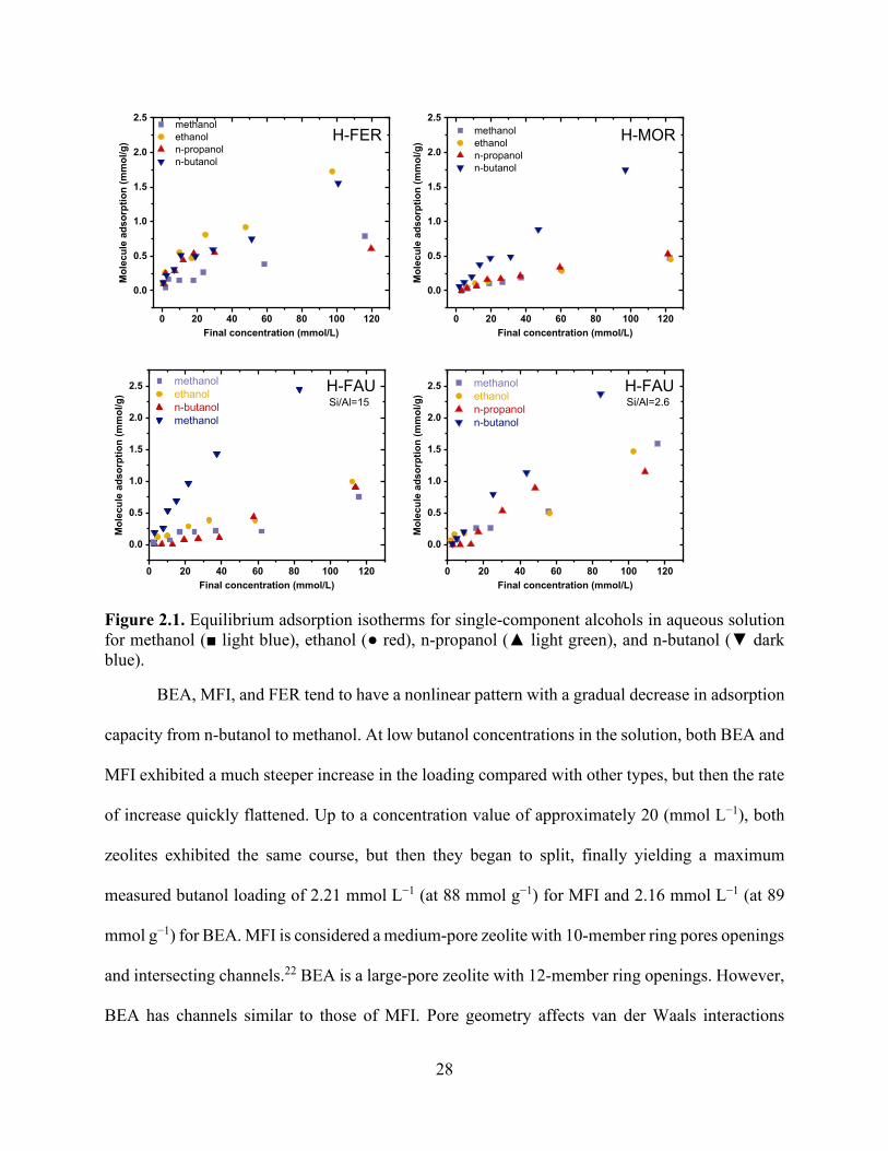
28
Figure 2.1. Equilibrium adsorption isotherms for single-component alcohols in aqueous solution for methanol (■ light blue), ethanol (● red), n-propanol (▲ light green), and n-butanol (▼ dark blue).
BEA, MFI, and FER tend to have a nonlinear pattern with a gradual decrease in adsorption
capacity from n-butanol to methanol. At low butanol concentrations in the solution, both BEA and
MFI exhibited a much steeper increase in the loading compared with other types, but then the rate
of increase quickly flattened. Up to a concentration value of approximately 20 (mmol L−1), both
zeolites exhibited the same course, but then they began to split, finally yielding a maximum
measured butanol loading of 2.21 mmol L−1 (at 88 mmol g−1) for MFI and 2.16 mmol L−1 (at 89
mmol g−1) for BEA. MFI is considered a medium-pore zeolite with 10-member ring pores openings
and intersecting channels.22 BEA is a large-pore zeolite with 12-member ring openings. However,
BEA has channels similar to those of MFI. Pore geometry affects van der Waals interactions
0 20 40 60 80 100 120
0.0
0.5
1.0
1.5
2.0
2.5
H-FER methanol ethanol n-propanol n-butanol
Mol
ecul
e ad
sorp
tion
(mm
ol/g
)
Final concentration (mmol/L)0 20 40 60 80 100 120
0.0
0.5
1.0
1.5
2.0
2.5
H-MOR methanol ethanol n-propanol n-butanol
Mol
ecul
e ad
sorp
tion
(mm
ol/g
)
Final concentration (mmol/L)
0 20 40 60 80 100 120
0.0
0.5
1.0
1.5
2.0
2.5Si/Al=15H-FAU methanol
ethanol n-butanol methanol
Mol
ecul
e ad
sorp
tion
(mm
ol/g
)
Final concentration (mmol/L)0 20 40 60 80 100 120
0.0
0.5
1.0
1.5
2.0
2.5Si/Al=2.6H-FAU methanol
ethanol n-propanol n-butanol
Mol
ecul
e ad
sorp
tion
(mm
ol/g
)
Final concentration (mmol/L)

29
between the organic substance and the framework oxygen atoms.4 The scale of affinity observed
for MFI and BEA was as expected: increasing affinity with increasing molecular weight and
decreasing polarity.16
In FER, the n-butanol and ethanol isotherm adsorption slopes were similar, as were those
of methanol and n-propanol, which had lower isotherm slopes. The same behavior was
documented in earlier studies7 when the adsorption of ethylene glycol was higher than that of
propylene glycol. Another study mentioned similar trends for linear and disbranched alkanes.23
Previous studies have demonstrated that linear alkanes with fewer than five carbons are adsorbed
in both 8-member ring (MR) and 10-MR channels, whereas more than five carbons preferentially
adsorb in the 10-MR channels.24,25 In a previous study, isotherm experiments with n-butanol and
ethanol using CHA (3.8 × 4.2 a) and LTA (4.2 × 4.2 a) cage types demonstrated opposite
selectivity; the adsorption of ethanol was favorable on CHA (which has a similar kinematic
diameter to FER 8-ring channels), whereas the LTA (which has a similar kinematic diameter to
FER 10-ring channels) topology had a clear preference for n-butanol.18 These results indicate a
molecular sieving property of FER zeolites for ethanol in 8-ring channels and an n-butanol
confinement preference in 10-ring channels.
MOR and FAU exhibited linear trends over the studied region. FAU is considered a large-
size zeolite. However, MOR is considered a medium-size zeolite despite its 12-MR openings
because its channels are straight and do not have intersections. They have highly different pore
structures, but both showed linear adsorption. MOR showed an increase in the adsorption capacity
with an increasing carbon number. However, this effect was abrupt at C4 rather than proceeding
gradually from C1 to C3. The small adsorption of C1–C3 in MOR suggests that side pockets are

30
inaccessible due to its minor axis (4.3 Å). Adsorption of n-butanol in MOR appeared to be linear
and did not follow a defined pattern based on the molecule sizes.
High-alumina samples of FAU (Si/Al = 2.6) in shorter-chain alcohols exhibited higher
adsorption values than normal FAU did (Si/Al = 15). Adsorption of shorter-chain alcohols in
aqueous solution at lower concentrations was higher with more defects due to the considerable
amount of water adsorbed into the framework. Water and shorter-chain alcohols have strong
interactions within the framework that significantly enhance adsorption.26 The adsorption of the
longer-chain alcohols at lower concentrations varied slightly and even decreased with increasing
aqueous-phase concentration. Hydrogen ions and water molecules occupy pore space and therefore
hinder the adsorption of the alcohols at higher concentrations.26 Hydrophilic sites had a more
substantial effect on the adsorption of shorter-chain alcohols at low concentrations than on that of
the longer-chain alcohols. The crossover from higher n-propanol loading to higher methanol and
ethanol loading in the adsorption isotherms occurred at 20 mmol/L.
Oxygenates of various oxygen functional groups behave differently in adsorption onto
zeolites. In principle, adsorption affinity is a function of adsorbate functionality.4 Figure 2.2 shows
adsorption for aldehydes and ketones on MFI and BEA. The longer nonpolar C-chain of n-
butyraldehyde promotes adsorption over n-butanol and propanol in MFI and BEA types.
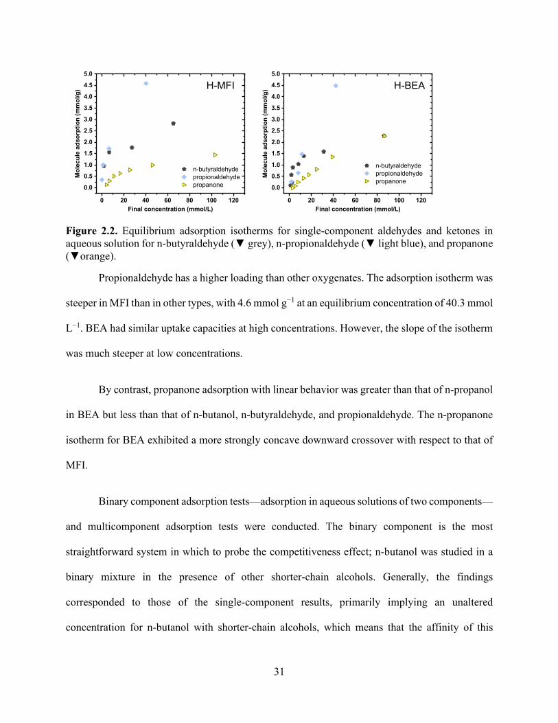
31
Figure 2.2. Equilibrium adsorption isotherms for single-component aldehydes and ketones in aqueous solution for n-butyraldehyde (▼ grey), n-propionaldehyde (▼ light blue), and propanone (▼orange).
Propionaldehyde has a higher loading than other oxygenates. The adsorption isotherm was
steeper in MFI than in other types, with 4.6 mmol g−1 at an equilibrium concentration of 40.3 mmol
L−1. BEA had similar uptake capacities at high concentrations. However, the slope of the isotherm
was much steeper at low concentrations.
By contrast, propanone adsorption with linear behavior was greater than that of n-propanol
in BEA but less than that of n-butanol, n-butyraldehyde, and propionaldehyde. The n-propanone
isotherm for BEA exhibited a more strongly concave downward crossover with respect to that of
MFI.
Binary component adsorption tests—adsorption in aqueous solutions of two components—
and multicomponent adsorption tests were conducted. The binary component is the most
straightforward system in which to probe the competitiveness effect; n-butanol was studied in a
binary mixture in the presence of other shorter-chain alcohols. Generally, the findings
corresponded to those of the single-component results, primarily implying an unaltered
concentration for n-butanol with shorter-chain alcohols, which means that the affinity of this
0 20 40 60 80 100 120
0.0
0.5
1.0
1.5
2.0
2.5
3.0
3.5
4.0
4.5
5.0
H-MFI
n-butyraldehyde propionaldehyde propanone
Mol
ecul
e ad
sorp
tion
(mm
ol/g
)
Final concentration (mmol/L)0 20 40 60 80 100 120
0.0
0.5
1.0
1.5
2.0
2.5
3.0
3.5
4.0
4.5
5.0
H-BEA
n-butyraldehyde propionaldehyde propanone
Mol
ecul
e ad
sorp
tion
(mm
ol/g
)
Final concentration (mmol/L)

32
molecule was not affected by the presence of smaller molecules within the same functional group.
High n-butanol selectivity over the other molecules was observed due to the stronger dispersive
interactions with the zeolite framework. Methanol and ethanol were completely excluded, and n-
propanol showed negligible competition with n-butanol. In FER, adsorption isotherms of n-
butanol and ethanol were similar to those of their corresponding single-component systems,
meaning that n-butanol and ethanol are adsorbed into different sites and do not compete with the
same active types. The FER channels were occupied simultaneously by both molecules.
Straight-chain alcohols are compared to branched-chain alcohols in BEA in Figure 2.3. In
the single-component isotherms, 2-butanol exhibited lower adsorption capacity than n-butanol did,
which is consistent with the results of a previous study.27 Shape selectivity arises through a tradeoff
between entropy and enthalpy.27 Adsorption of linear-chain butanol alcohols maximizes the
enthalpy contribution and minimizes entropy losses. When both molecules are present in the
mixture, n-butanol and 2-butanol adsorption occurs simultaneously.
0 20 40 60 80 100 120
0.0
0.5
1.0
1.5
2.0
2.5
3.0
TernaryH-BEA ethanol in ternary solution
n-propanol in ternary solution n-butanol in ternary solution
Mol
ecul
e ad
sorp
tion
(mm
ol/g
)
Final concentration (mmol/L)0 20 40 60 80 100 120
0.0
0.5
1.0
1.5
2.0
2.5
3.0
n-butanol reduction
2-butanol reduction
H-BEA 2-butanol w/ n-butanol n-butanol w/ 2-butanol 2-butanol n-butanol
Mol
ecul
e ad
sorp
tion
(mm
ol/g
)
Final concentration (mmol/L)
single componentbinary component

33
Figure 2.3. Equilibrium adsorption isotherms for multicomponent alcohols in aqueous solution for methanol (■ light blue), ethanol (● red), n-propanol (▲ light green), n-butanol (▼ dark blue), and 2-butanol (▼light blue).
The equilibrium loading of n-butyraldehyde was higher than that of butanol (Figure 2.4).
The strong competition between n-butanol and n-butyraldehyde is due to their similar chemical
structure, but n-butyraldehyde is more hydrophilic. N-butanol loading decreased in the presence
of n-butyraldehyde for all the adsorbents.
0 20 40 60 80 100 120
0.0
0.5
1.0
1.5
2.0
2.5
3.0
n-butanol reduction
n-propanol reduction
H-MFI n-propanol w/ n-butanol n-butanol w/ n-propanol n-propanol n-butanol
Mol
ecul
e ad
sorp
tion
(mm
ol/g
)
Final concentration (mmmol/L)
single componentbinary component
0 20 40 60 80 100 120
0.0
0.5
1.0
1.5
2.0
2.5
3.0
and ethanol isotherm
H-FER n-propanol in ternary solution n-butanol in ternary solution ethanol in ternary solution n-butanol from single solution ethanol from single solution n-propanol from single solution
Mol
ecul
e ad
sorp
tion
(mm
ol/g
)
Final concentration (mmol/L)
no change in n-butanol
drop in n-propanol isotherm
0 20 40 60 80 100 120
0.0
0.5
1.0
1.5
2.0
2.5
3.0
3.5
4.0
4.5
5.0
reduction inn-butanol
H-MFI
n-propionaldehyde w/ n-butanol n-butanol w/ propionaldehyde n-butanol n-propionaldehyde
Mol
ecul
e ad
sorp
tion
(mm
ol/g
)
Final concentration (mmol/L)
reduction inn-propionaldehyde binary component
single component
0 20 40 60 80 100 120
0.0
0.5
1.0
1.5
2.0
2.5
3.0
3.5
4.0
4.5
5.0
reduction inn-butanol
H-BEA
n-propionaldehyde w/ n-butanol n-butanol w/ propionaldehyde n-butanol n-propionaldehyde
Mol
ecul
e ad
sorp
tion
(mm
ol/g
)
Final concentration (mmol/L)
reduction inn-propionaldehyde
single componentbinary component
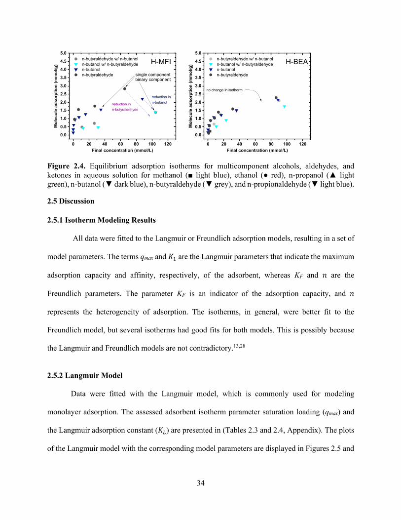
34
Figure 2.4. Equilibrium adsorption isotherms for multicomponent alcohols, aldehydes, and ketones in aqueous solution for methanol (■ light blue), ethanol (● red), n-propanol (▲ light green), n-butanol (▼ dark blue), n-butyraldehyde (▼ grey), and n-propionaldehyde (▼ light blue).
2.5 Discussion
2.5.1 Isotherm Modeling Results
All data were fitted to the Langmuir or Freundlich adsorption models, resulting in a set of
model parameters. The terms qmax and 𝐾𝐾1 are the Langmuir parameters that indicate the maximum
adsorption capacity and affinity, respectively, of the adsorbent, whereas KF and 𝑛𝑛 are the
Freundlich parameters. The parameter KF is an indicator of the adsorption capacity, and 𝑛𝑛
represents the heterogeneity of adsorption. The isotherms, in general, were better fit to the
Freundlich model, but several isotherms had good fits for both models. This is possibly because
the Langmuir and Freundlich models are not contradictory.13,28
2.5.2 Langmuir Model
Data were fitted with the Langmuir model, which is commonly used for modeling
monolayer adsorption. The assessed adsorbent isotherm parameter saturation loading (qmax) and
the Langmuir adsorption constant (𝐾𝐾𝐿𝐿) are presented in (Tables 2.3 and 2.4, Appendix). The plots
of the Langmuir model with the corresponding model parameters are displayed in Figures 2.5 and
0 20 40 60 80 100 120
0.0
0.5
1.0
1.5
2.0
2.5
3.0
3.5
4.0
4.5
5.0
reduction inn-butanol
H-MFI n-butyraldehyde w/ n-butanol n-butanol w/ n-butyraldehyde n-butanol n-butyraldehyde
Mol
ecul
e ad
sorp
tion
(mm
ol/g
)
Final concentration (mmol/L)
reduction inn-butyraldehyde
binary component single component
0 20 40 60 80 100 120
0.0
0.5
1.0
1.5
2.0
2.5
3.0
3.5
4.0
4.5
5.0
H-BEA n-butyraldehyde w/ n-butanol n-butanol w/ n-butyraldehyde n-butanol n-butyraldehyde
Mol
ecul
e ad
sorp
tion
(mm
ol/g
)
Final concentration (mmol/L)
no change in isotherm

35
2.6. The monolayer capacity generally increases with increasing zeolite pore size, with the qmax
values for BEA and MFI being similar.
Figure 2.5. Model isotherms for single-component alcohols in aqueous solution for methanol (■ light blue), ethanol (● red), n-propanol (▲ light green), n-butanol (▼ dark blue). The symbols show experimental values, and the solid and dashed lines show the Langmuir and Freundlich model results, respectively.
0 20 40 60 80 100 120
0.0
0.5
1.0
1.5
2.0
2.5
H-MFI
Symbol = Exp.Line = LangmuirDash = Freundlich
methanol ethanol n-propanol n-butanol
Mol
ecul
e ad
sorp
tion
(mm
ol/g
)
Final concentration (mmol/L)0 20 40 60 80 100 120
0.0
0.5
1.0
1.5
2.0
2.5
Symbol = Exp.Line = LangmuirDash = Freundlich
H-MOR methanol ethanol n-propanol n-butanol
Mol
ecul
e ad
sorp
tion
(mm
ol/g
)Final concentration (mmol/L)
0 20 40 60 80 100 120
0.0
0.5
1.0
1.5
2.0
2.5
H-BEA methanol ethanol n-propanol n-butanol
Mol
ecul
e ad
sorp
tion
(mm
ol/g
)
Final concentration (mmol/L)
Symbol = Exp.Line = LangmuirDash = Freundlich
0 20 40 60 80 100 120
0.0
0.5
1.0
1.5
2.0
2.5
Symbol = Exp.Line = LangmuirDash = Freundlich
H-FER methanol ethanol n-propanol n-butanol
Mol
ecul
e ad
sorp
tion
(mm
ol/g
)
Final concentration (mmol/L)
0 20 40 60 80 100 120
0.0
0.5
1.0
1.5
2.0
2.5
3.0
3.5
4.0
4.5
5.0
Symbol = Exp.Line = LangmuirDash = Freundlich
H-MFI n-butyraldehyde propionaldehyde propanone
Mol
ecul
e ad
sorp
tion
(mm
ol/g
)
Final concentration (mmol/L)0 20 40 60 80 100 120
0.0
0.5
1.0
1.5
2.0
2.5
3.0
3.5
4.0
4.5
5.0
Symbol = Exp.Line = LangmuirDash = Freundlich
H-BEA n-butyraldehyde propionaldehyde propanone
Mol
ecul
e ad
sorp
tion
(mm
ol/g
)
Final concentration (mmol/L)

36
Figure 2.6. Model isotherms for single-component aldehydes and ketones in aqueous solution for n-butyraldehyde (▼ grey), n-propionaldehyde (▼ light blue), and propanone (▼ orange). The symbols show experimental values, and the solid and dashed lines show the Langmuir and Freundlich model results, respectively.
The Langmuir model assumes monolayer adsorption over adsorbent sites1; no further
adsorption occurs after molecules occupy a site. The model can be explained by examining the
loadings in terms of the number of molecules per active site to eliminate the effect of varying
formula weights. Molecular clustering, which can be induced by hydrogen bonding, causes the
maximum adsorption factor per alumina factor to exceed unity.29 In MFI and BEA, more than one
ethanol and one n-propanol molecule are adsorbed per site (Figure 2.7 a). By contrast, a smaller
adsorption capacity for n-alcohols occurs in FAU with a Si/Al ratio of 2.6, indicating that only a
certain fraction of the Brønsted acid sites are accessible to the adsorbing n-alcohol molecules
(Figure 2.7 b).
Figure 2.7. The number of charge-balancing cations for each zeolite type for (a) the comparison of n-butanol and n-propanol adsorption over FER, MFI, and BEA and (b) n-butanol adsorption with FAU with Si/Al ratios of 2.6, 15 and 80.
In FER, MFI, and BEA, the total number of molecules adsorbed exceeded the number of
active sites available per gram of zeolite (Figure 2.7 a), and stronger interaction confirmed
0 20 40 60 80 100 120
0.0
0.5
1.0
1.5
2.0
2.5
BEAMFI
# of
cha
rge-
bala
ncin
g ca
tions
(mm
ol/g
)
n-propanol, FER n-butanol, FER n-propanol, BEA n-butanol, BEA n-propanol, MFI n-butanol, MFI
Mol
ecul
e ad
sopt
ion
(mm
ol/g
)
Final concentration (mmol/L)
FER
1.11.21.4
theoretical maximum adsorption capacity
(a)
0 20 40 60 80 100 120
0.00.51.01.52.02.53.03.54.04.55.05.56.0
Si/Al = 15
Si/Al = 2.6
H-FAU
# of
cha
rge-
bala
ncin
g ca
tions
(mm
ol/g
)
Si/Al = 2.6 Si/Al = 80 Si/Al = 15
Mol
ecul
e ad
sorp
tion
(mm
ol/g
)
Final concentration (mmol/L)
0.94
4.4
(b)

37
multiple-site occupancy. This observation implies that adsorption occurs everywhere through the
channel walls, not just at the Brønsted acid sites. The adsorption isotherms and energetics vary in
a sophisticated manner depending on the composition of the solid adsorbent and on the size and
shape of the pores that constitute the solid. A more advanced model is required to decouple
adsorption at multiple types of sites, which probably limits the use of simple models to describe
adsorption. The adsorption constant (KL) for the Langmuir isotherm model in BEA and MFI
revealed more robust interactions at low coverage. This is expected because of the strongly
concave downward shape of these isotherms. The low adsorption constant on FAU for smaller n-
alcohols can be attributed to the large size of FAU zeolites associated with a large cavity diameter
of approximately 11.9 Å (Table 2.2).
Table 2.2. Zeolite topological characteristics for channels and cages.30
Framework Channels Cages Pore
Limiting Diameter
Type Ring Size
Channel Pathway
Largest Cavity
Diameter
Percentage of Pore
Volume in Cages (%)
ZSM-5 10 Sinusoidal 7 26 5 10 Straight
FER 10 Straight 7 47 5.3 8 Straight
FAU 12 Straight 11.9 77 6.7 BEA 12 Straight 6.9 20 6.7
12 Straight

38
2.5.3 Freundlich Adsorption Isotherm
The Freundlich isotherm models for BEA and MFI were consistent with the Langmuir
isotherm; as generally reported, adsorption increases in distinct patterns for each carbon number.
For both types, the Freundlich adsorption intensity parameter increased with increasing carbon
number, similar to the increase in the adsorption constant in the Langmuir model. Sorption was
better fitted to the Freundlich equation, which suggests that adsorption occurs at heterogeneous
reactive sites and is probably a multilayer process (Tables 2.5 and 2.6, Appendix).31 Isotherms that
deviated from a Langmuir isotherm were plotted according to the Freundlich model. Simplified
models such as the linear and Langmuir isotherm models are less likely to be followed for the
single adsorption of alcohol in aqueous solution. These results are attributed to multilayer
adsorption, especially with larger molecules. To predict the adsorption behavior of the
multicomponent solution system, a multicomponent Freundlich isotherm model was used to study
the experiments results of this study (Eq. 18). Parameters 𝐾𝐾F, 𝑛𝑛, and 𝑎𝑎𝑎𝑎𝑗𝑗 for the multicomponent
adsorption isotherms for each component are given in Tables 2.7–2.13 in the Appendix. The
coefficients shown in these tables explain the adsorption influence of a specific molecule by the
presence of the other molecule in the solution. For example, n-butanol absorption was not affected
by the presence of all the other smaller n-alcohols molecules, which were mainly ethanol and
methanol, whereas, in the case of oxygenates of different oxygen functional groups such as n-
propionaldehyde and n-butyraldehyde, the presence of other components on n-butanol adsorption
was rather high. Figure 2.8 shows the Freundlich competitive adsorption coefficient for binary n-
butanol in the presence of each molecule for various zeolite types. For n-propanol, competitive
adsorption coefficients were estimated to be 0.133 for MFI. Because ethanol and methanol have
no significant influence on the parameter, their estimated parameter coefficient was negligible and

39
omitted. Figure 2.8 a, also indicates that the coefficient value (effect) increases with carbon
numbers from methanol (𝑎𝑎𝑎𝑎𝑗𝑗 = 0.0013) to 2-butanol (𝑎𝑎𝑎𝑎𝑗𝑗 = 1.51) for BEA zeolite. The same trend
was noticed in H-MFI (Figure 2.8 b). However, n-butyraldehyde had more effect on n-butanol (𝑎𝑎𝑎𝑎𝑗𝑗
= 1.77). Results indicated that the model fit the data obtained from all experiments relatively well
and could be applied to study and predict the adsorption behavior of multicomponent system
present in an ABE fermentation solution that is obtained from the biomass route.
Figure 2.8. Competitive adsorption coefficients for methanol, ethanol, n-propanol, n-propionaldehyde, n-butyraldehyde, and 2-butanol with n-butanol for (a) BEA and (b) MFI.
2.6 Conclusion
We demonstrated that adsorption on zeolites from aqueous solution is a viable and
attractive method for separation. Five types of commercial zeolites were assessed as possible
options for n-butanol recovery. Adsorption isotherms of n-butanol, n-propanol, ethanol, and
methanol were determined. By adopting the Langmuir model, underlying assumptions can be
applied to understand conceptual meaning of the model due its physical means. However,
providing a complete theoretical assessment is complicated, and thus, reasonable assumptions have
been used to simplify the explanations of the Langmuir model. Langmuir isotherm models were
0.0
0.2
0.4
0.6
0.8
1.0
1.2
1.4
1.6
1.8
2.0
com
petit
ive
adso
rptio
n co
effic
ient
(aij)
molecule competing with n-butanol
methanol ethanol propanol 2-butanol n-propionaldehyde n-butyraldehyde
(a)BEA
0.0
0.2
0.4
0.6
0.8
1.0
1.2
1.4
1.6
1.8
2.0
com
petit
ive
adso
rptio
n co
effic
ient
(aij)
molecule competing with n-butanol
methanol ethanol propanol n-propionaldehyde n-butyraldehyde
(b)MFI

40
less likely to follow the single-adsorption mechanism of alcohol in aqueous solution. These results
were due to multilayer adsorption, especially for longer-chain alcohols. Isotherms deviating from
the Langmuir isotherm were plotted according to the Freundlich model. Competitive adsorption
coefficients were correlated to the influence of the other molecules present. However, due to the
empirical basis of the Freundlich model, the model could not be correlated to physical adsorption
interactions and zeolite sizes. The topology of a zeolite plays a role in allowing smaller molecules
to enter small channels and larger ones to be adsorbed preferentially, leading to different active
site adsorption in a heterogeneous system.

41
2.7 Appendix Table 2.3. Langmuir parameters for a single component system for BEA, MFI, and FER.
Zeolite type BEA MFI FER
Sample 𝐾𝐾L (L mol-1)
qmax (mmol g-1)
𝐾𝐾L (L mol-1)
qmax (mmol g-1)
𝐾𝐾L (L mol-1)
qmax (mmol g-1)
methanol 42 ± 15 1.01 ± 0.13 18.0 ± 5.8 0.96 ± 0.0 4.7 ± 4.3 2.15 ± 1.42 ethanol 3.8 ± 1.8 4.2 ± 1.4 17.6 ± 4.4 2.24 ± 0.3 14.0 ± 7.8 2.83 ± 0.88
n-propanol 15.7 ± 5.1 2.6 ± 0.44 73.0 ± 0.01 1.7 ± ± 0.0 180 ± 5 0.64 ± 0.05 n-butanol 71.3 ± 18 2.6 ± 0 153 ± 52 2.2 ± 0.01 9.8 ± 6.6 2.90 ± 1.20
n-propionaldehyde 7.3 ± 0.06 18.8 ± 0.14 67 ± 44 6.2 ± 1.5 - -
n-butyraldehyde 106 ± 33 2.4 ± 0.3 174 ± 71 2.8 ± 0 - - propanone 4.7 ± 1.8 7.9 ± 2.3 27 ± 4.2 1.9 ± 0.13 - -
Table 2.4. Langmuir parameters for a single component system for MOR and FAU.
Zeolite type MOR FAU (Si/Al=15)
Sample 𝐾𝐾L (L mol-1)
qmax (mmol g-1)
𝐾𝐾L (L mol-1)
qmax (mmol g-1)
methanol 4.5 ± 1.0 1.36 ± 0.22 - - ethanol 11.0 ± 3.0 0.77 ± 0.11 - -
n-propanol 6.3 ± 1.5 1.23 ± 0.20 - - n-butanol 15.0 ± 14.7 13.6 ± 12.0 8.9 ± 1.4 5.8 ± 0.6
n-propionaldehyde - - - - n-butyraldehyde - - - -
propanone - - - -
Table 2.5. Freundlich parameters for a single component system for BEA, MFI, and FER.
Zeolite type BEA MFI FER
Sample KF (L mol-1) n KF (L mol-1) n KF (L mol-
1) n
methanol 0.11 ± 0.05 2.2 ± 0.6 0.008 ± 0 0.99 ± 0.14 0.02 ± 0.01 1.39 ± 0.20 ethanol 0.03 ± 0.06 1.3 ± 0.7 0.10 ± 0.01 1.74 ± 0.09 0.12 ± 0.04 1.72 ± 0.23
n-propanol 0.09 ± 0.02 1.6 ± 0.1 0.28 ± 0.05 2.53 ± 0.28 0.21 ± 0.04 4.07 ± 1.01 n-butanol 0.58 ± 0.03 3.5 ± 0.2 0.67 ± 0.10 3.87 ± 0.63 0.08 ± 0.02 1.62 ± 0.22
n-propionaldehyde 0.18 ± 0.01 1.17 ± 0.02 0.78 ± 0.21 2.1 ± 0.4 - - n-butyraldehyde 0.42 ±0.09 2.6 ± 0.4 0.82 ± 0.2 3.5 ± 0.88 - -

42
propanone 0.05 ± 0.01 1.15 ± 0.08 0.13 ± 0.02 1.91± 0.17 - -
Table 2.6. Freundlich parameters for a single component system for MOR and FAU.
Zeolite type MOR FAU (Si/Al=15)
Sample KF (L mol-1) n KF (L mol-1) n
methanol 0.01 ± 0.00 1.27 ± 0.002 0.005 ± 0.005 0.96 ± 0.22 ethanol 0.02 ± 0.002 1.62 ± 0.006 0.018 ± 0.010 1.2 ± 0.20
n-propanol 0.014 ± 0.003 1.32 ± 0.096 0.005 ± 0.003 0.96 ± 0.003 n-butanol 0.027 ±0.006 1.10 ± 0.071 0.083 ± 0.012 1.31 ± 0.072
n-propionaldehyde - - - - n-butyraldehyde - - - -
propanone - - - -
Table 2.7. Competitive adsorption coefficients for methanol, ethanol, and n-propanol with n-butanol.
coefficient value
single coefficient K=0.82 n=3.5
aii 1 1 1 1 1 1 aij 0.0051 0.0013 0.0164 0.00245 0.133 0.148
main Molecule methanol ethanol n-propanol
other Molecule n-butanol
conc. Ratio 1 1 1 1 1 1 R2 0.94 0.98 0.91 0.94 0.86 0.92
zeolite type H-MFI H-BEA H-MFI H-BEA H-MFI H-BEA
Table 2.8. Competitive adsorption coefficients for n-propionaldehyde and n-butyraldehyde with n-butanol.
coefficient value
single coefficient K=0.18 n=1.17
K=0.82 n=3.5
aii 1 1 1 1 aij 285.42 285.42 2.51 0.62
main Molecule n-propionaldehyde n-butyraldehyde other Molecule n-butanol
conc. Ratio 1 1 1 1 R2 0.94 0.94 0.91 0.91
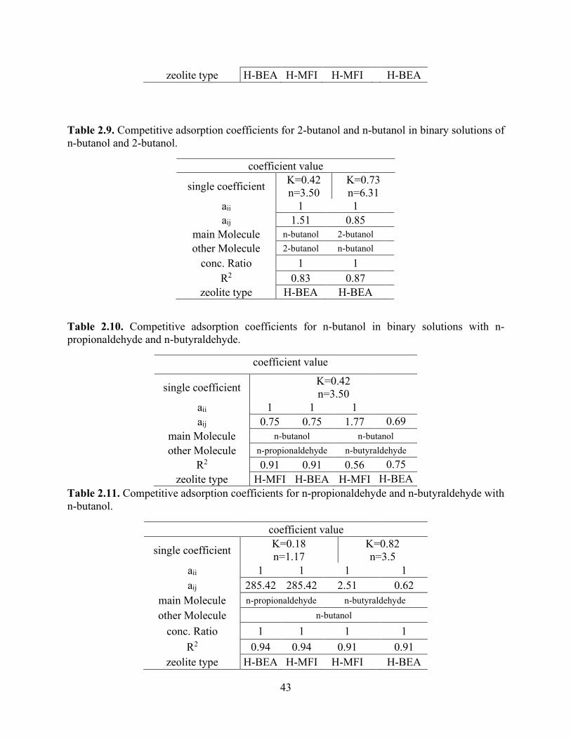
43
zeolite type H-BEA H-MFI H-MFI H-BEA
Table 2.9. Competitive adsorption coefficients for 2-butanol and n-butanol in binary solutions of n-butanol and 2-butanol.
coefficient value
single coefficient K=0.42 n=3.50
K=0.73 n=6.31
aii 1 1 aij 1.51 0.85
main Molecule n-butanol 2-butanol other Molecule 2-butanol n-butanol
conc. Ratio 1 1 R2 0.83 0.87
zeolite type H-BEA H-BEA
Table 2.10. Competitive adsorption coefficients for n-butanol in binary solutions with n-propionaldehyde and n-butyraldehyde.
coefficient value
single coefficient K=0.42 n=3.50
aii 1 1 1 aij 0.75 0.75 1.77 0.69
main Molecule n-butanol n-butanol other Molecule n-propionaldehyde n-butyraldehyde
R2 0.91 0.91 0.56 0.75 zeolite type H-MFI H-BEA H-MFI H-BEA
Table 2.11. Competitive adsorption coefficients for n-propionaldehyde and n-butyraldehyde with n-butanol.
coefficient value
single coefficient K=0.18 n=1.17
K=0.82 n=3.5
aii 1 1 1 1 aij 285.42 285.42 2.51 0.62
main Molecule n-propionaldehyde n-butyraldehyde other Molecule n-butanol
conc. Ratio 1 1 1 1 R2 0.94 0.94 0.91 0.91
zeolite type H-BEA H-MFI H-MFI H-BEA

44
2.8 References
1. Bates, S. P.; Van Well, W. J. M.; Van Santen, R. A.; Smit, B. Energetics of N-Alkanes in
Zeolites: A Configurational-Bias Monte Carlo Investigation into Pore Size Dependence. J.
Am. Chem. Soc. 1996, 118, 6753–6759.
2. Eder, F.; Lercher, J. A. On the Role of the Pore Size and Tortuosity for Sorption of Alkanes in
Molecular Sieves. J. Phys. Chem. B 1997, 101, 1273–1278.
3. First, E. L.; Gounaris, C. E.; Wei, J.; Floudas, C. A. Computational Characterization of Zeolite
Porous Networks: An Automated Approach. Phys. Chem. Chem. Phys. 2011, 13, 17339–
17358.
4. Foo, K. Y.; Hameed, B. H. Insights into the Modeling of Adsorption Isotherm Systems. Chem.
Eng. J. 2010, 156, 2–10.
5. Freundlich, H. Über Die Adsorption in Lösungen. Zeitschrift für Physikalische Chemie 1907,
57U, 385.
6. Goerlitz, R.; Weisleder, L.; Wuttig, S.; Trippel, S.; Karstens, K.; Goetz, P.; Niebelschuetz, H.
Bio-Butanol Downstream Processing: Regeneration of Adsorbents and Selective Exclusion of
Fermentation by-Products. Adsorption 2018, 24, 95–104.
7. Janda, A.; Vlaisavljevich, B.; Smit, B.; Lin, L.-C.; Bell, A. T. Effects of Pore and Cage
Topology on the Thermodynamics of N-Alkane Adsorption at Brønsted Protons in Zeolites at
High Temperature. J. Phys. Chem. C 2017, 121, 1618–1638.
8. Krishna, R.; Van Baten, J. M. Hydrogen Bonding Effects in Adsorption of Water−Alcohol
Mixtures in Zeolites and the Consequences for the Characteristics of the Maxwell−Stefan
Diffusivities. Langmuir 2010, 26, 10854–10867.
9. Kulprathipanja, S. Zeolites in Industrial Separation and Catalysis; John Wiley & Sons, 2010.

45
10. Langmuir, I. The Adsorption of Gases on Plane Surfaces of Glass, Mica and Platinum. J. Am.
Chem. Soc. 1918, 40, 1361–1403.
11. Mallon, E. E. Aqueous Solution and Vapor Phase Adsorption of Oxygenates onto Zeolites.
Thesis, University of Minnesota, 2012.
12. Mallon, E. E.; Babineau, I. J.; Kranz, J. I.; Guefrachi, Y.; Siepmann, J. I.; Bhan, A.; Tsapatsis,
M. Correlations for Adsorption of Oxygenates onto Zeolites from Aqueous Solutions. J. Phys.
Chem. B 2011, 115, 11431–11438.
13. Mallon, E. E.; Bhan, A.; Tsapatsis, M. Driving Forces for Adsorption of Polyols onto Zeolites
from Aqueous Solutions. J. Phys. Chem. B 2010, 114, 1939–1945.
14. Nguyen, C. M.; Reyniers, M.-F.; Marin, G. B. Theoretical Study of the Adsorption of C1–C4
Primary Alcohols in H-Zsm-5. Phys. Chem. Chem. Phys. 2010, 12, 9481–9493.
15. Nguyen, C. M.; Reyniers, M.-F.; Marin, G. B. Theoretical Study of the Adsorption of the
Butanol Isomers in H-Zsm-5. J. Phys. Chem. C 2011, 115, 8658–8669.
16. Nguyen, C. M.; Reyniers, M.-F.; Marin, G. B. Adsorption Thermodynamics of C1–C4
Alcohols in H-Fau, H-Mor, H-Zsm-5, and H-Zsm-22. J. Catal. 2015, 322, 91–103.
17. Raganati, F.; Procentese, A.; Olivieri, G.; Russo, M. E.; Salatino, P.; Marzocchella, A. Bio-
Butanol Separation by Adsorption on Various Materials: Assessment of Isotherms and Effects
of Other Abe-Fermentation Compounds. Sep. Purif. Technol. 2018, 191, 328–339.
18. Remy, T.; Cousin Saint Remi, J.; Singh, R.; Webley, P. A.; Baron, G. V.; Denayer, J. F. M.
Adsorption and Separation of C1−C8 Alcohols on Sapo-34. J. Phys. Chem. C 2011, 115, 8117–
8125.
19. Sheindorf, C.; Rebhun, M.; Sheintuch, M. A Freundlich-Type Multicomponent Isotherm. J.
Colloid Interface Sci. 1981, 79, 136–142.

46
20. Skopp, J. Derivation of the Freundlich Adsorption Isotherm from Kinetics. J. Chem. Educ.
2009, 86, 1341.
21. Smit, B.; Maesen, T. L. M. Towards a Molecular Understanding of Shape Selectivity. Nature
2008, 451, 671–678.
22. Stückenschneider, K.; Merz, J.; Schembecker, G. Molecular Interactions of Alcohols with
Zeolite Bea and Mor Frameworks. J. Mol. Model. 2013, 19, 5611–5624.
23. Van den Bergh, M.; Van de Voorde, B.; De Vos, D. Adsorption and Selective Recovery of
Citric Acid with Poly(4-Vinylpyridine). ChemSusChem 2017, 10, 4864–4871.
24. Van der Mynsbrugge, J.; Hemelsoet, K.; Vandichel, M.; Waroquier, M.; Van Speybroeck, V.
Efficient Approach for the Computational Study of Alcohol and Nitrile Adsorption in H-Zsm-
5. J. Phys. Chem. C 2012, 116, 5499–5508.
25. Van Koningsveld, H. High-Temperature (350 K) Orthorhombic Framework Structure of
Zeolite H-Zsm-5. Acta Crystallogr., Sect. B 1990, 46, 731–735.
26. Van Well, W. J. M.; Cottin, X.; de Haan, J. W.; Smit, B.; Nivarthy, G.; Lercher, J. A.; van
Hooff, J. H. C.; Van Santen, R. A. Chain Length Effects of Linear Alkanes in Zeolite Ferrierite.
1. Sorption and 13c Nmr Experiments. J. Phys. Chem. B 1998, 102, 3945–3951.
27. Van der Perre, S.; Gelin, P.; Claessens, B.; Martin-Calvo, A.; Cousin Saint Remi, J.; Duerinck,
T.; Baron, G. V.; Palomino, M.; Sánchez, L. Y.; Valencia, S.; Shang, J.; Singh, R.; Webley, P.
A.; Rey, F.; Denayer, J. F. M. Intensified Biobutanol Recovery by Using Zeolites with
Complementary Selectivity. ChemSusChem 2017, 10, 2968–2977.
28. Weitkamp, J.; Puppe, L. Catalysis and Zeolites: Fundamentals and Applications; Springer:
Berlin Heidelberg, 2013.

47
29. Worch, E. Adsorption Technology in Water Treatment: Fundamentals, Processes, and
Modeling; De Gruyter: Berlin, 2012.
30. Xiong, R.; Sandler, S. I.; Vlachos, D. G. Molecular Screening of Alcohol and Polyol
Adsorption onto Mfi-Type Zeolites. Langmuir 2012, 28, 4491–4499.
31. Yu, S.; Wang, X.; Yao, W.; Wang, J.; Ji, Y.; Ai, Y.; Alsaedi, A.; Hayat, T.; Wang, X.
Macroscopic, Spectroscopic, and Theoretical Investigation for the Interaction of Phenol and
Naphthol on Reduced Graphene Oxide. Environ. Sci. Technol. 2017, 51, 3278–3286.

48
Chapter 3: Efficient Hydrogen Production from N-butanol Steam Reforming Obtained from ABE Fermentation Using RD
3.1 Abstract
An increase in n-butanol production is a consequence of the growth in biomass production
and makes utilizing n-butanol as a feedstock attractive (e.g., for the production of hydrogen). Here,
we report integrating n-butanol steam reforming and adsorption–desorption into a single process
as a potential approach to enhance the efficiency of n-butanol adsorption from ABE and hydrogen
production. A base case process, operating with normal butanol reforming, was investigated. A
thermodynamic analysis was used to compare n-butanol steam reforming with and without
integration with the adsorption–desorption process, highlighting higher efficiency for hydrogen
production and energy utilization. This report recommends a reforming temperature of 800 °C and
a steam-to-carbon ratio of 10 to ensure the lowest energy usage to generate a particular amount of
hydrogen.

49
3.2 Introduction
Growing population and economic development have resulted in more energy demand over
the last two decades. Living standard improvements have also strengthened the need for energy.1
Among the various sources of energy, petroleum is the most significant. Its derivatives are
significant in transportation, electricity, and raw materials for the petrochemical industry. These
resources are facing an inevitable increase in demand, and their usage is becoming a major
concern.2
Plants produce 128 billion metric tons of carbohydrate biomass every year through
photosynthesis.3 Several potential biologically based routes to synthesize commodity chemicals
from biomass exist.4 Biomass is one of the world’s single largest renewable energy resources,
contributing to 10% of the world’s primary energy supply.5 Compared with other emerging liquid
fuel sources, biomass is thought to have the most potential. With the gradual shift toward a more
carbohydrate-based economy, in 2030, it is anticipated that 20% of transportation fuels and 25%
of chemicals, including 45 billion pounds of biobased chemicals and bioproducts, will be produced
from biomass.3 Due to its abundance and growing production, biomass could help alleviate
concerns regarding energy security and climate change. The mitigation of climate change is
achieved by offsetting the carbon produced by fuel burning and reducing greenhouse gas
emissions. Because CO2 emissions from combustion are consumed by plants during the process
of photosynthesis, more biomass is produced, and biomass has the potential to reduce 550 million
tons of CO2 every year.3
The composition of biomass contains two major carbohydrates, cellulose and
hemicellulose, which are bound together by polymeric lignin. The three resulting biopolymers are
valuable because of their ability to extract energy from the sun. Lignocellulosic biomass is often

50
referred to as a second-generation feedstock and is one of the most significant applications of
biorefineries for the production of biofuels due to its abundance and affordability; moreover, its
use does not affect the food supply. The potential biomass energy to be produced in 2050 has been
estimated to be in the range of 150–450 exajoule/year, representing an equivalent amount of 76 ×
109 barrels of oil equivalent.3,6 Lignocellulosic biomass is a nonedible residue obtained from
agriculture, forestry, urban, and industrial reuses.7 It can be converted into solid, liquid, and
gaseous fuels through various technologies of thermal, thermochemical, and biochemical
conversion. Different reactions are involved in these steps, including hydrolysis, dehydration,
isomerization, oxidation, dehydrogenation, and hydrogenation, which occur in processes such as
combustion, pyrolysis, gasification, alcoholic fermentation, and liquefaction.8
In the biochemical conversion process, lignocellulosic biomass follows two production
routes (those using ABE and isopropanol–butanol–ethanol). These production routes are
challenged by low production yield and high energy use for separation.9 Therefore, alternative
separation techniques to distillation are more attractive and promising for integration. Several
online recovery methods have been studied, including adsorption, liquid–liquid extraction,
pervaporation, and gas stripping. Among them, adsorption is the most promising separation
process to separate the required molecules from fermentation broths.10 The material and energy
balances reported by Qureshi et al. suggest that the energy needed to recover n-butanol from
fermentation broth using zeolites as adsorbents is 1,948 kcal/kg compared to 5,789 kcal/kg through
distillation or gas stripping.11 The process of adsorption involves adsorbing the required molecules
on the surface of the adsorbent (zeolite in this study) and then desorbing them by increasing the
temperature. Different factors affect adsorption, such as adsorption capacity, selectivity, affinity,
and desorption, which are subject to adsorbent type.12 Existing adsorption separation techniques

51
are directly connected with high energy consumption but are still the most economical option.11
However, these techniques are connected with cyclic work and the consumption of a substantial
amount of steam for regeneration. Operating adsorption equipment requires regenerating part or
all of the adsorbed components to be diverted to downstream facilities with a hot stream that may
not be an economical choice. Increasing the temperature of the regeneration stream through a series
of heat exchangers leads to higher consumption of steam and electricity, ultimately requiring more
energy. This approach substantially increases operational costs, making it highly difficult to
operate this separation process without having to reduce the energy associated with the process.
Integrating separation with an additional reaction process (intensified process) to generate more
valuable products is a highly attractive route for improving efficiency and thereby reducing costs.
To address the impact of adsorption–desorption efficiency, the RD process optimizes the use of
desorption energy to generate more valuable products and minimize the downstream processes
needed to separate the hot stream from the desorbed components. This process has the potential to
yield more valuable products and reduce equipment size and throughput. In this process, the
desorbed outlet stream is integrated with an n-butanol steam reforming unit. There are two steps
in the operation of this reaction system: adsorption and RD. In the first step, the fermentation
stream is fed into an adsorber, and the adsorbent becomes slowly saturated with n-butanol. In the
second step, the n-butanol is desorbed from the adsorbent by means of an inert regeneration gas
(e.g., N2) and an increase in temperature. The amount of heat released during the regeneration step
is used for the integration with endothermic n-butanol steam reforming. The key point of this step
is to use the energy used for adsorbent regeneration in the subsequent reaction step. The N2 in the
effluent may be used as a carrier gas.

52
Steam reforming is one primary routes for n-butanol that involves a strongly endothermic
reaction (∆𝐻𝐻298° = 206.2 and 558.3 kJ mol−1 for natural gas and n-butanol steam reforming,
respectively); thus, the desorbed stream is useful for reducing this energy requirement.13,14 N-
butanol can be converted into H2 through steam reforming,15,16 POX,17 dry reforming (DR),18 and
ATR. POX and ATR have faster start-up times due to exothermic reactions. However, the steam
reforming process provides more H2 yield and fewer side reactions. This process is conducted in
two steps: first, n-butanol is converted to H2, CO, and CO2; then, CO is converted to CO2 in the
WGS reaction. Several studies have been conducted on steam reforming of n-butanol, and these
have revealed that hydrogen-rich gas production from renewable biomass or biomass-derived
chemicals is a promising hydrogen production direction.19,20 To improve hydrogen production,
minimize methane formation, and avoid coke deposition, thermodynamic analysis suggests
operating the reforming process at a high temperature (>900 K), a high steam-to-n-butanol ratio
(>9), and atmospheric pressure. However, under these operating conditions, the produced gas
contains a high content of CO; thus, the WGS reaction is used to convert CO to CO2. It is
thermodynamically possible to perform steam reforming of oxygenates with a C:O ratio of 1:1 at
200–400 K less than that required by alkanes with a similar carbon number.21 Oxygenated
hydrocarbon reforming presents several advantages related to natural availability, including
renewable production from several biomass utilization resources that require a dedicated and
flexible processing facility. Like most industrial applications, this process is driven by economic
constraints and sustainability criteria, such as low-cost operation and resource-efficient use.
Therefore, the challenge is to produce environmentally friendly products with small carbon
numbers having at least comparable or better properties than fossil fuels at competitive prices.
Combining several processes in an integrated manner is useful for process optimization, and hence,

53
generating valuable marketable products.22 One of the major challenges for efficient biomass
processing is the ability to optimize product extraction. Currently used extraction and fractionation
techniques may cause a dramatic loss of potential value for biomass components due to the
pretreatment and separation steps. Hence, more research should focus on the maximization and
process development of value extraction to establish cost-effective biorefinery operations for
separation and upgrading as well as to meet the current infrastructure of fuel systems. Here, we
present a current and potential application of adsorption by zeolites in process intensification. The
objective of this paper is to outline and illustrate an alternative intensified process separation
technique. In the initial stage of the study, the adsorption of n-butanol molecules from fermentation
aqueous solution were investigated. Building on this foundation, an investigation of a possible
integration process for a more intensified process of upgrading was undertaken. A thermodynamic
approach to steam reforming of oxygenated n-butanol and a mixture of n-butanol and butene
obtained from desorption23,24 was studied to determine favorable operating conditions to produce
hydrogen. The influences of steam, steam-to-fuel, and feed molar ratios and temperature on the
product gas concentration were investigated. This effort to integrate experimental work with
process simulation to develop a comprehensive design for separation and reaction of the system
has rarely been discussed in the literature, and yet, further process improvements remain to be
discovered. The analysis in this report includes product recovery specifications and process
operations, and they are presented for two possible cases of integration. Finally, anticipated
problems and further recommendations are mentioned.

54
3.3 Process Description
3.3.1 Baseline
3.3.1.1 Adsorption Process
Adsorption is defined as a separation process that involves two phases in which two
components are separated. It is the result of interactive forces of physical attraction between
surfaces of porous solids and component molecules being removed from the bulk phase.25 First,
the adsorption process is accomplished in a fixed bed using zeolites. Adsorption in liquid
adsorbents is accomplished by passing the liquid down through a bed of zeolites in a liquid
absorber. Another liquid absorber is used in the regeneration cycle. Zeolites have a strong affinity
for some molecules, as determined by isotherm analysis.26 Once zeolites are saturated, the liquid
adsorber must be taken off-stream and regenerated using a hot-flow stream such as nitrogen. This
occurs in every full cycle of adsorption until equilibrium conditions are approached and may also
be influenced by bed performance and feed conditions. Adsorption is described through isotherms,
which are functions that connect the amount of adsorbate taken by the adsorbent with the
adsorptive equilibrium concentration c and temperature T, with all other parameters being
constant.27
This connection is based on the pressure of the gas phase and the concentration of the liquid
phase. In actual practice, adsorption isotherms represent the equilibrium states of an adsorption
system. They give useful information about adsorbates, adsorbents, and adsorption processes.28
This usefulness may be extended to the determination of adsorbent surface area, pore volume, and
size distribution.29 Furthermore, these isotherms give more information on the magnitudes of
adsorption enthalpy as well as the relative adsorbability of a molecule on a solid surface at specific

55
standards. Different isotherm equations, such as those of Langmuir30 and Freundlich,31 might be
used to represent the adsorption data. Figure 3.1 shows a simplified flow diagram of the adsorption
process.
Figure 3.1. Simplified flow diagram of the adsorption process.
3.3.1.2 Steam Reforming Process
As shown in Figure 3.2, n-butanol is vaporized, mixed with steam, and heated to the inlet
temperature of the reformer in the preheater. At lower temperatures, steam reforming of
oxygenated hydrocarbons is favored thermodynamically to that of nonoxygenated hydrocarbons
because the former is more exothermic.32 The stoichiometric reaction of maximum hydrogen
production is
𝐶𝐶𝑥𝑥𝐻𝐻𝑦𝑦𝑂𝑂𝑧𝑧 + (2𝑥𝑥 − 𝑧𝑧)𝐻𝐻2𝑂𝑂 ⟶ (2𝑥𝑥 − 𝑧𝑧 + 0.5𝑦𝑦)𝐻𝐻2 + 𝑥𝑥𝐶𝐶𝑂𝑂2 (1)
Steam reforming of oxygenated hydrocarbons involves complicated reaction systems that
produce undesirable reaction paths.33 To obtain the maximum hydrogen yield, the steam reforming
process is completed in three steps: oxygenated hydrocarbon conversion to H2, CH4, CO, and CO2;

56
a lower temperature step that converts CO to CO2 and H2 through the WGS reaction; and
conversion of the remaining CO into CO2 through preferential CO oxidation in a third reactor.34
Figure 3.2. Simplified flow diagram of H2 production from the n-butanol steam reforming process.
3.3.2 Advanced Process
Desorption is the reverse process of adsorption in which adsorbates are desorbed by
increasing the temperature to produce concentrated adsorbates in the outlet stream.35 Four common
processes can be applied for desorption of adsorbed species: pressure swing, purge gas stripping,
desorption displacement, and thermal swing operation. The first two processes are not practical in
the case of n-butanol desorption due to the low vapor pressure of n-butanol at ambient
temperature.10,24 The RD process optimizes the use of desorption energy to generate more valuable
products and minimize the downstream processes needed to separate the hot stream from the
desorbed components. In this process, a regeneration gas is fed to the adsorbents from the
compressor and hot gas stream. Reported desorption temperatures in the literature range from 200
to 450 °C for a desorption composition mixture of n-butanol and 1-butene.24 Experimental
recovery of n-butanol by desorption from adsorbates has resulted in an endothermic peak due to a

57
dehydration chemical reaction, leading to 1-butene formation.23,24 Table 3.1 presents the
compositions of n-butanol, 1-butene, and water desorbed from 0.385 g of dry extrudate at different
temperatures. At 150 °C, 80% of the adsorbed n-butanol was desorbed, and the remaining 18%
was desorbed as 1-butene at temperatures >250 °C.23 A comparison of the two previous basic
configurations suggests that a hybrid process should be explored to combine the advantages of the
two basic configurations.
Figure 3.3. Simplified flow diagram of the integrated approach; the combined desorber–reactor system operation includes a desorption outlet feed to the steam reforming reactor.
Table 3.1. Compositions of n-butanol, 1-butene, and water desorbed from 0.385 g of dry extrudate (containing 0.308 g of zeolite) at different temperatures. The table was normalized in mmol/g of solid using the data in Saravanan (2009).23
Temperature (◦C) Composition (mmol/g) n-butanol 1-butene water
50 0.33 0.0 16.01 150 1.24 0.0 0.29 250 0.0619 0.075 0.13 350 0.007 0.008 0.10 450 0 0.003 0.05

58
3.4 Modeling Methodology
3.4.1 Aspen Plus Flowsheet
Figure 3.4 shows an Aspen Plus flowsheet of the n-butanol steam reformer. Aspen Plus
was used to perform all the equilibrium composition calculations. A “Gibbs reactor” was used to
calculate the product composition and the heat of the overall reaction.
Figure 3.4. Aspen Plus flowsheet of the n-butanol steam reformer.
3.4.2 Minimization of Gibbs Free Energy
Minimization of the total Gibbs free energy is a suitable approach for calculating the
equilibrium composition of any reaction system.36 This approach accounts for the many
simultaneous reactions that occur.
The Gibbs free energy of a system is given by
𝐺𝐺𝑎𝑎 = ∑ 𝑛𝑛𝑎𝑎𝐺𝐺𝑎𝑎 = ∑ 𝑛𝑛𝑎𝑎𝜇𝜇𝑎𝑎 =𝑁𝑁𝑎𝑎=1
𝑁𝑁𝑎𝑎=1 ∑ 𝜇𝜇𝑎𝑎𝐺𝐺𝑎𝑎0 + 𝑅𝑅𝑅𝑅∑𝑛𝑛𝑎𝑎 ln 𝑜𝑜𝑖𝑖
𝑜𝑜𝑖𝑖0
𝑁𝑁𝑎𝑎=1 (2)
𝜇𝜇𝑎𝑎 = ∆𝐺𝐺𝑜𝑜𝑎𝑎0 + 𝑅𝑅𝑅𝑅 ln 𝑜𝑜𝑖𝑖𝑜𝑜𝑖𝑖0 (3)

59
where 𝐺𝐺𝑎𝑎 is the total Gibbs free energy, 𝑁𝑁 in the reaction system number of species, 𝑛𝑛𝑎𝑎 is the moles
of species i, 𝜇𝜇𝑎𝑎 is the chemical potential, ∆𝐺𝐺𝑜𝑜𝑎𝑎0 is the standard Gibbs function of the formation of
species 𝑖𝑖, 𝑅𝑅 is the molar gas constant, 𝑅𝑅 is the temperature of the system, 𝑓𝑓𝑎𝑎 is the fugacity in the
system, and 𝑓𝑓𝑎𝑎0 is the standard-state fugacity. The equilibrium reaction in the gas phase is
represented as
𝑓𝑓𝑎𝑎 = 𝑦𝑦𝑎𝑎𝜙𝜙𝑎𝑎𝑃𝑃, 𝑓𝑓𝑎𝑎0 = 𝑃𝑃0 (4)
where 𝑃𝑃 is the pressure of the system, 𝜙𝜙𝑎𝑎 is the fugacity coefficient of species 𝑖𝑖, 𝑦𝑦𝑎𝑎 is the molar
fraction of species 𝑖𝑖, and 𝑃𝑃0 is the standard-state pressure.
By using the method of Lagrange multiplier, the minimum Gibbs free energy of the total
system can be expressed as
∑ 𝑛𝑛𝑎𝑎𝑎𝑎𝑎𝑎𝑘𝑘 = 𝑏𝑏𝑘𝑘𝑁𝑁𝑎𝑎=1 𝑘𝑘 = 1, …𝑀𝑀 (5)
∑ 𝑛𝑛𝑎𝑎 �∆𝐺𝐺𝑜𝑜𝑎𝑎0 + 𝑅𝑅𝑅𝑅 ln 𝑜𝑜𝑖𝑖𝑜𝑜𝑖𝑖0 + ∑ 𝜆𝜆𝑎𝑎𝛼𝛼𝑎𝑎𝑘𝑘𝑘𝑘 � = 0𝑁𝑁
𝑎𝑎=1 (6)
A Gibbs reactor was used to calculate product compositions under conditions to minimize Gibbs
free energy. The equation of state used for fugacity calculations was the Peng–Robinson method.
In the simulations, the reaction temperature was varied in the range of 500–800 °C and 1 atm. The
inlet steam-to-fuel molar ratio ranged from 1:1 to 20:1.
3.4.3 N-Butanol Reforming
The possible reactions of n-butanol steam reforming are described by Eqs. 7–25. The steam
reforming process of C4H10O produces H2 and CO (Eq. 7). This is a strongly endothermic reaction

60
(∆𝐻𝐻2980 = −558.32 𝑘𝑘𝑘𝑘/𝑚𝑚𝑚𝑚𝑚𝑚).15,16 C4H10O can dehydrogenate to butanal according to Eq. 18
(∆𝐻𝐻2980 = −86.47 𝑘𝑘𝑘𝑘/𝑚𝑚𝑚𝑚𝑚𝑚).
The n-butanol steam reforming process involves the following reactions14,20:
N-butanol steam reforming reaction
𝐶𝐶4𝐻𝐻10𝑂𝑂 + 3𝐻𝐻2𝑂𝑂 ⇋ 4𝐶𝐶𝑂𝑂 + 8𝐻𝐻2 ∆𝐻𝐻2980 = 558.32 𝑘𝑘𝑘𝑘/𝑚𝑚𝑚𝑚𝑚𝑚 (7)
𝐶𝐶4𝐻𝐻10𝑂𝑂 + 7𝐻𝐻2𝑂𝑂 ⇋ 4𝐶𝐶𝑂𝑂 + 12𝐻𝐻2 ∆𝐻𝐻2980 = 394 𝑘𝑘𝑘𝑘/𝑚𝑚𝑚𝑚𝑚𝑚 (8)
WGS reaction
𝐶𝐶𝑂𝑂 + 𝐻𝐻2𝑂𝑂 ⇋ 𝐶𝐶𝑂𝑂2 + 𝐻𝐻2 ∆𝐻𝐻2980 = −41.09 𝑘𝑘𝑘𝑘/𝑚𝑚𝑚𝑚𝑚𝑚 (9)
Hydrogenation of carbon monoxide
𝐶𝐶𝑂𝑂 + 3𝐻𝐻2 ⇋ 𝐶𝐶𝐻𝐻4 + 𝐻𝐻2𝑂𝑂 ∆𝐻𝐻2980 = −205.21 𝑘𝑘𝑘𝑘/𝑚𝑚𝑚𝑚𝑚𝑚 (10)
𝐶𝐶𝑂𝑂 + 4𝐻𝐻2 ⇋ 𝐶𝐶𝐻𝐻4 + 2𝐻𝐻2𝑂𝑂 ∆𝐻𝐻2980 = −164.95 𝑘𝑘𝑘𝑘/𝑚𝑚𝑚𝑚𝑚𝑚 (11)
2𝐶𝐶𝑂𝑂 + 2𝐻𝐻2 ⇋ 𝐶𝐶𝑂𝑂2 + 𝐶𝐶𝐻𝐻4 ∆𝐻𝐻2980 = −260.5 𝑘𝑘𝑘𝑘/𝑚𝑚𝑚𝑚𝑚𝑚 (12)
Hydrogenation of carbon dioxide
𝐶𝐶𝑂𝑂2 + 4𝐻𝐻2 ⇋ 𝐶𝐶𝐻𝐻4 + 2𝐻𝐻2𝑂𝑂 ∆𝐻𝐻2980 = −165.0 𝑘𝑘𝑘𝑘/𝑚𝑚𝑚𝑚𝑚𝑚 (13)
Methane steam reforming
𝐶𝐶𝐻𝐻4 + 𝐻𝐻2𝑂𝑂 ⇋ 𝐶𝐶𝑂𝑂 + 3𝐻𝐻2 ∆𝐻𝐻2980 = 206 𝑘𝑘𝑘𝑘/𝑚𝑚𝑚𝑚𝑚𝑚 (14)
𝐶𝐶𝐻𝐻4 + 2𝐻𝐻2𝑂𝑂 ⇋ 𝐶𝐶𝑂𝑂 + 4𝐻𝐻2 ∆𝐻𝐻2980 = 164.95 𝑘𝑘𝑘𝑘/𝑚𝑚𝑚𝑚𝑚𝑚 (15)
Methane dry reforming

61
𝐶𝐶𝐻𝐻4 + 𝐶𝐶𝑂𝑂2 ⇋ 2𝐶𝐶𝑂𝑂 + 2𝐻𝐻2 ∆𝐻𝐻2980 = 247 𝑘𝑘𝑘𝑘/𝑚𝑚𝑚𝑚𝑚𝑚 (16)
Reverse WGS (RWGS) reaction
𝐶𝐶𝑂𝑂2 + 𝐻𝐻2 ⇋ 𝐶𝐶𝑂𝑂 + 𝐻𝐻2𝑂𝑂 ∆𝐻𝐻2980 = 41.09 𝑘𝑘𝑘𝑘/𝑚𝑚𝑚𝑚𝑚𝑚 (17)
Dehydrogenation of n-butanol
𝐶𝐶4𝐻𝐻10𝑂𝑂 ⇋ 𝐶𝐶4𝐻𝐻8𝑂𝑂 + 𝐻𝐻2 ∆𝐻𝐻2980 = −86.47 𝑘𝑘𝑘𝑘/𝑚𝑚𝑚𝑚𝑚𝑚 (18)
Dehydration of n-butanol
𝐶𝐶4𝐻𝐻10𝑂𝑂 ⇋ 𝐶𝐶4𝐻𝐻8 + 𝐻𝐻2𝑂𝑂 ∆𝐻𝐻2980 = −24.04 𝑘𝑘𝑘𝑘/𝑚𝑚𝑚𝑚𝑚𝑚 (19)
Decomposition of n-butanol to propane
𝐶𝐶4𝐻𝐻10 ⇌ 𝐶𝐶3𝐻𝐻8 + 𝐶𝐶𝑂𝑂 + 𝐻𝐻2𝑂𝑂 ∆𝐻𝐻2980 = 11.98 𝑘𝑘𝑘𝑘/𝑚𝑚𝑚𝑚𝑚𝑚 (20)
Ethylene production
𝐶𝐶3𝐻𝐻8𝑂𝑂 ⇌ 𝐶𝐶2𝐻𝐻4 + 𝐶𝐶𝐻𝐻4 ∆𝐻𝐻2980 = 81.65 𝑘𝑘𝑘𝑘/𝑚𝑚𝑚𝑚𝑚𝑚 (21)
Ethylene to hydrogen
𝐶𝐶2𝐻𝐻4 ⇌ 𝐶𝐶2𝐻𝐻2 + 𝐻𝐻2 ∆𝐻𝐻2980 = 175.0 𝑘𝑘𝑘𝑘/𝑚𝑚𝑚𝑚𝑚𝑚 (22)
Butene isomerization
𝐶𝐶4𝐻𝐻8 ⇋ 𝑖𝑖 − 𝐶𝐶4𝐻𝐻10 (23)
𝐶𝐶4𝐻𝐻8 ⇋ 𝑐𝑐𝑖𝑖𝑐𝑐 − 2 − 𝐶𝐶4𝐻𝐻10 + 𝑡𝑡𝑟𝑟𝑎𝑎𝑛𝑛𝑐𝑐 − 2 − 𝐶𝐶4𝐻𝐻10 (24)
𝑐𝑐𝑖𝑖𝑐𝑐 − 2 − 𝐶𝐶4𝐻𝐻10 + 𝑡𝑡𝑟𝑟𝑎𝑎𝑛𝑛𝑐𝑐 − 2 − 𝐶𝐶4𝐻𝐻10 ⇋ 𝑖𝑖 − 𝐶𝐶4𝐻𝐻10 (25)
Butene hydrogenation

62
𝐶𝐶4𝐻𝐻8 + 𝐻𝐻2 ⇋ 𝐶𝐶4𝐻𝐻10 (26)
Butene reforming
𝐶𝐶4𝐻𝐻8 + 4𝐻𝐻2𝑂𝑂 ⇋ 4𝐶𝐶𝑂𝑂 + 8𝐻𝐻2 (27)
The equilibrium conversions of reactants and hydrogen yield
Conversion of 𝐶𝐶4𝐻𝐻10𝑂𝑂 (%) = 𝐹𝐹𝑛𝑛−𝑏𝑏𝑏𝑏𝑏𝑏𝑚𝑚𝑛𝑛𝑏𝑏𝑏𝑏,𝑖𝑖𝑛𝑛−𝐹𝐹𝑛𝑛−𝑏𝑏𝑏𝑏𝑏𝑏𝑚𝑚𝑛𝑛𝑏𝑏𝑏𝑏,𝑏𝑏𝑏𝑏𝑏𝑏𝐹𝐹𝑛𝑛−𝑏𝑏𝑏𝑏𝑏𝑏𝑚𝑚𝑛𝑛𝑏𝑏𝑏𝑏,𝑖𝑖𝑛𝑛
× 100 (28)
Conversion of 𝐻𝐻2𝑂𝑂 (%) = 𝐹𝐹𝐻𝐻2𝑂𝑂,𝑖𝑖𝑛𝑛−𝐹𝐹𝐻𝐻2𝑂𝑂,𝑏𝑏𝑏𝑏𝑏𝑏
𝐹𝐹𝐻𝐻2𝑂𝑂,𝑖𝑖𝑛𝑛× 100 (29)
𝐻𝐻2 yield (%) = 𝐹𝐹𝐻𝐻2 ,𝑎𝑎𝑎𝑎/𝐹𝐹𝐶𝐶4𝐻𝐻10𝑂𝑂,𝑎𝑎𝑎𝑎 × 1/8 (30)
The model described was used to perform sensitivity analysis. During sensitivity analysis,
the model input values were kept the same, and a parameter was varied. The calculation procedure
for thermal efficiency was based on the approach developed by He and collaborators.19 In the
conversion of fuel into hydrogen using a steam reforming process, the efficiency of the reaction
can be calculated as follows:
𝜂𝜂 =𝑎𝑎𝐻𝐻2𝑏𝑏𝑏𝑏𝑏𝑏∙𝐿𝐿𝐻𝐻𝐿𝐿𝐻𝐻2
�𝑎𝑎𝑓𝑓𝑏𝑏𝑒𝑒𝑏𝑏𝑖𝑖𝑛𝑛 ∙𝐿𝐿𝐻𝐻𝐿𝐿𝑓𝑓𝑏𝑏𝑒𝑒𝑏𝑏+𝑄𝑄𝑖𝑖𝑛𝑛𝑖𝑖𝑏𝑏𝑏𝑏,𝑆𝑆𝑆𝑆+𝑎𝑎𝑠𝑠𝑏𝑏𝑒𝑒𝑚𝑚𝑚𝑚
𝑖𝑖𝑛𝑛 ∙∆𝐻𝐻𝑏𝑏𝑚𝑚𝑏𝑏𝑒𝑒𝑛𝑛𝑏𝑏� (31)
where 𝑛𝑛𝐻𝐻2𝑜𝑜𝑁𝑁𝑎𝑎 is the number of moles of H2 in the outlet stream at equilibrium, 𝑛𝑛𝑜𝑜𝑁𝑁𝑒𝑒𝑎𝑎𝑎𝑎𝑎𝑎 and
𝑛𝑛𝑎𝑎𝑎𝑎𝑒𝑒𝑎𝑎𝑁𝑁𝑎𝑎𝑎𝑎 are the numbers of moles of fuel and steam in the inlet stream, respectively, ∆𝐻𝐻𝑎𝑎𝑎𝑎𝑎𝑎𝑒𝑒𝑎𝑎𝑎𝑎 is the
latent energy of the feed stream, 𝐿𝐿𝐻𝐻𝑉𝑉𝐻𝐻2 is the lower heating value of hydrogen, and 𝐿𝐿𝐻𝐻𝑉𝑉𝑜𝑜𝑁𝑁𝑒𝑒𝑎𝑎 is the
lower heating value of the fuel. The lower heating value of n-butanol is 2444.6 kJ mol−1, and the
lower heating value of hydrogen is 239.2 kJ mol−1.

63
3.5 Experimental Methods
3.5.1 Materials
Zeolites with small-, medium-, and large-size pores and various Si/Al ratios were used to
examine the thermodynamic, kinetic, and molecular sieve effects and their consequences on
adsorption. The ammonium forms of BEA and MFI zeolites were purchased from Zeolyst
International (see Table 3.2 for formulas and Si/Al ratios) and converted to the proton form through
treatment in ambient air at 823 K (rate of 0.2 K s−1) for 10 h. Methanol (99.8%, Sigma-Aldrich),
ethanol (95%, Sigma-Aldrich), n-propanol (99.7%, Sigma-Aldrich), and n-butanol (99.4%, Sigma-
Aldrich) were purchased and used as received without additional purification.
Table 3.2. Zeolite frameworks and properties.
Zeolite name Framework Si/Al n BEA |H+
n| [AlnSi64-n O128]-*BEA 12.5 4.74 MFI |H+
n (H2O)16| [AlnSi96-n O192]-MFI 11.5 7.6
3.5.2 Batch Adsorption Equilibria Tests
Adsorption isotherms were collected using 5 mL of 0.003–0.132 M aqueous solutions of
methanol, ethanol, n-propanol, and/or n-butanol. Zeolite samples (0.1–0.5 g) were added to these
solutions, and the solutions were shaken periodically until equilibrium was achieved (24–36 h).
The concentration of alcohol(s) in the liquid was measured daily, and equilibrium was determined
to have been reached when concentrations remained constant for more than 12 h. Analysis of the
liquid phase was conducted using GC-MS (Agilent 5980 GC coupled to 7890 MS; Agilent J&W
HP-5 GC Column, 50 m, 0.32 mm, 0.52 µm). The solutions were filtered using a 3-mL Monoject
syringe fitted with a 0.2-μm polypropylene filter to remove solids before GC-MS analysis. Initial

64
and final liquid-phase concentrations, along with solution volumes, were used to calculate the
number of molecules adsorbed onto zeolites. Measurements of molecules adsorbed into zeolites
were only calculated through liquid-phase measurements. Solid-phase alcohol concentrations were
expressed in terms of moles of adsorbate per mass of adsorbent, according to equation 3137:
𝑞𝑞 = (𝐶𝐶𝑒𝑒 − 𝐶𝐶0)𝑉𝑉/𝑊𝑊 (32)
where 𝐶𝐶0 and 𝐶𝐶𝑒𝑒 represent the initial and equilibrium concentrations of adsorbate, respectively
(mol/l), V is the volume of solution, and W is the mass of adsorbent.
3.6 Results and Discussion
3.6.1 Adsorption Capacities
Alcohols and water were absorbed in different types of zeolites. Zeolites exhibit molecular
sieve properties due to well-defined pore and cavity structures. The effective channel detects
whether a molecule that has a specific critical molecular diameter can diffuse into the cage and
adsorb.
The maximum capacity for each individual component was estimated to be 2.2 and 1.7
[mmol/g] for n-butanol and n-propanol (Figure 3.5), respectively. A binary component system is
the most straightforward system with which to study the effects of a multicomponent system.
Competitive adsorption was noticed between n-butanol and n-propanol in their binary system. This
is a simple illustration of the competitive adsorption case in which n-butanol affinity is much
higher than that of methanol, leading to full active site occupation by n-butanol. In this case, the
n-butanol adsorption isotherm was studied to account for the presence of other molecules.

65
Generally, the findings correspond to the single-component results and imply unaltered
concentrations for n-butanol, meaning that the affinity of such molecules was not affected by the
presence of smaller molecules within the same functional group. However, smaller molecules
exhibited lower adsorption capacity in the presence of n-butanol, and these findings are in
agreement with a previously concluded on a factor affecting adsorption performance,
confinement.26,38–43 The adsorption isotherms of n-butanol on MFI zeolites in the presence of
methanol, ethanol, and n-propanol in binary solutions, each with n-butanol, show similar behavior
as in those of the individual components, except for n-propanol with increased competitiveness to
be presented. This finding could be attributed to the competition between these additional
molecules for the same active sites that n-butanol is attracted to. The binary mixture of n-butanol
and methanol exhibited almost identical adsorption constants. The second-most simplified
competitive adsorption was that between n-butanol and n-propanol in BEA. Both molecules
showed high adsorption capacity in their individual component systems, and as expected, they
competed for the same active site, but the sites had high affinity towards n-butanol due to
confinement and other effects, as indicated earlier. The presence of some interactions between
different system components may have affected this result and changed the saturation adsorption
capacity. In a multicomponent system, confinement has a major impact on competitiveness factors.

66
Figure 3.5. Equilibrium adsorption isotherms for single-component and multicomponent alcohols in aqueous solution for methanol (■ light blue), ethanol (● red), n-propanol (▲ light green), and n-butanol (▼ dark blue).
3.6.2 Steam Reforming
3.6.2.1 Baseline
A traditional steam n-butanol reforming (SBR)-based hydrogen production flowsheet is
shown in Figure 3.4; its thorough material stream and energy flow data is provided in Tables 3.4-
3.12. The baseline SBR design consists of the following reactor building blocks: SBR, high-
temperature shift reaction, and low-temperature shift reaction. Each of these reactors operates near
equilibrium and is modeled using a Gibbs free energy minimization reactor in Aspen Plus. The
0 20 40 60 80 100 120
0.0
0.5
1.0
1.5
2.0
2.5
H-BEA methanol ethanol n-propanol n-butanol
Mol
ecul
e ad
sorb
ed (m
mol
/g)
Final concentration (mmmol/L)0 20 40 60 80 100 120
0.0
0.5
1.0
1.5
2.0
2.5
H-MFI methanol ethanol n-propanol n-butanol
Mol
ecul
e ad
sorb
ed (m
mol
/g)
Final concentration (mmmol/L)
0 20 40 60 80 100 120
0.0
0.5
1.0
1.5
2.0
2.5
3.0
TernaryH-BEA ethanol in ternary solution
n-propanol in ternary solution n-butanol in ternary solution
Mol
ecul
e ad
sorp
tion
(mm
ol/g
)
Final concentration (mmol/L)0 20 40 60 80 100 120
0.0
0.5
1.0
1.5
2.0
2.5
3.0
n-butanol reduction
n-propanol reduction
H-MFI n-propanol w/ n-butanol n-butanol w/ n-propanol n-propanol n-butanol
Mol
ecul
e ad
sorp
tion
(mm
ol/g
)
Final concentration (mmmol/L)
single componentbinary component

67
overall flow sheet inlets are 1 kmol/h C4H10O with varies flow rates of kmol/h H2O, and the
overall flow sheet outlets are 12 kmol/h H2.The C4H10O and H2O streams are heated to 500–800
°C and then mixed to form the reformer feed, which has a H2O/C4H10O molar ratio of 2:20; the
reformer operating pressure and temperature are1 bar and 500-800 °C, respectively.
Thermodynamic analysis predicts that during n-butanol reforming, hydrogen can be
produced from steam reforming of n-butanol, as illustrated by reaction 1 (Eq. 7), reaction 2 (Eq.
8), the WGS reaction (Eq. 9), SMR and DR of methane (DRM; Eqs. 14, 15, and 16), and
dehydrogenation of n-butanol (Eq. 18). Figure 3.6 shows the effects of the H2O/C4H9OH ratio and
temperature on n-butanol and H2O conversion and H2 yield. N-butanol conversion increased with
an increase in either the H2O/C4H9OH ratio or temperature (500–800 °C). More n-butanol was
converted at higher temperatures due to endothermic steam reforming. An increase in temperature
contributed to steam reforming and RWGS. The latter results in more H2O generation, whereas
the former reaction results in more H2O consumption. The WGS reaction is endothermic, which
means that with increasing temperature, CO and H2 increase. The H2 yield increases at low
temperatures due to steam reforming and WGS. At a higher temperature of approximately 700 °C,
the H2 yield increases to its maximum value. Both steam reforming and RWGS are endothermic.
The optimum steam reforming condition is determined by the maximization of reactant (C4H9OH
and H2O) conversion and H2 yield. At low temperatures, carbon monoxide was low due to
consumption in the carbon monoxide hydrogenation reaction (Eqs. 10, 11, and 12). Increasing
temperature increased carbon monoxide yield as a result of SMR and DRM (Eqs. 14, 15, and 16)
and RWGS (Eq. 17). This suggests that carbon monoxide formation can be inhibited at low
temperatures. Increasing the amount of steam shifted the equilibrium toward the WGS reaction
and the RWGS reaction toward hydrogen production. Figure 3.6 illustrates the effects of the

68
H2O/C4H9OH ratio and temperature on CO conversion and H2 yield. At low temperatures, almost
no carbon monoxide was observed. However, carbon dioxide and methane are the predominant
species to occur. Methane production is highest at the lowest temperature due to the methanation
reaction (Eqs. 12–15). As the temperature increases, more H2 is produced above 700 °C because
of the inhibition of the exothermic WGS reaction (Eq. 9).
The hydrogen content in the effluent is high for reformer temperatures above 700 °C and
increases slightly with increasing steam-to-n-butanol ratio. At temperatures >700 °C, the methane
concentration decreases while the CO concentration increases, reaching a maximum at a low
steam-to-n-butanol ratio and high temperature (T > 700 °C and H2O/C4H9OH ratio of 2:1 to 3:1).
The high concentration of CO is attributed to the WGS reaction behavior (reverse of Eq. 9). The
RWGS reaction and SMR are predominant at reaction temperatures above 800 K (527 °C).44 The
addition of water increases H2 and CO2 while reducing CO and methane.
Figure 3.6 (d) shows the effects of temperature and the water/n-butanol molar ratio on the
reaction conversion and product selectivity. It is evident that n-butanol converted to hydrogen
more often at higher temperatures (>600 °C) and water conversion increased with temperature.
Figure 3.6 (a) shows that energy increases have more impact with temperature than steam ratio,
suggesting that temperature has the higher impact.
Analysis of the basic configuration through energy estimation (Figure 3.7) suggests that
process designs with more complex arrangements should be explored to further reduce energy.

69
Figure 3.6. Effects of temperature and steam-to-n-butanol (H2O/C4H9OH) molar ratio on the dry basis molar concentration flow rate of (a) H2 and H2O conversion, (b) H2 and CO, (c) CO2 and CH4, and (d) H2, CH4, and CO product selectivities.
500 550 600 650 700 750 800
0
2
4
6
8
10
12
steam-to-n-butanol = 2
H2
H2 y
ield
(mol
/hr)
Temperature (°C)
steam-to-n-butanol = 3steam-to-n-butanol = 5steam-to-n-butanol =10
0
20
40
60
80
100
H2O conversion ratio = 10 ratio = 5 ratio = 3 ratio = 2
H2O
Con
vers
ion
(%)
500 550 600 650 700 750 8000
2
4
6
8
10
12 H2
ratio = 2H2 y
ield
(mol
/hr)
Temperature (°C)
ratio = 3ratio = 5
ratio =10
ratio = 10
ratio =3
ratio = 2
ratio = 5
0.0
0.5
1.0
1.5
2.0
2.5
3.0
3.5
4.0
CO
Car
bon
mon
oxid
e (m
ol/h
r)
500 550 600 650 700 750 800
0.0
0.5
1.0
1.5
2.0
2.5
3.0
3.5
4.0 CO2
ratio = 2
Car
bon
diox
ide
(mol
/hr)
Temperature (°C)
ratio = 3
ratio = 5
ratio =10
ratio = 10
ratio =3
ratio = 2
ratio = 5
0.0
0.5
1.0
1.5
2.0
2.5
3.0
CH4
Met
hane
(mol
/hr)
500 550 600 650 700 750 8000.0
0.1
0.2
0.3
0.4
0.5
0.6
0.7
0.8
ratio = 5
ratio = 3
ratio = 2
H2
H2/(
CO
+CO
2+C
H4)
Sele
ctiv
ity
Temperature (°C)
ratio= 3
ratio = 5ratio=10
ratio = 2
ratio = 5
ratio = 10
ratio = 5
ratio = 3
ratio = 2
0.0
0.1
0.2
0.3
0.4
0.5
0.6
0.7
0.8
CO CH4
CO
and
CH
4 se
lect
iviti
es
(a) (b)
(c) (d)

70
Figure 3.7. Influence of the reformer operating temperature and steam-to-n-butanol ratio on (a) hydrogen production and (b) total energy consumption by the process to obtain hydrogen yield in (a).
In this study, modeling was extended to evaluate the performance of a system with a
complex arrangement. Heat integration analysis for SBR-based hydrogen production was
performed for the baseline, and the integrated approach and results are shown in Figure 3.8. The
heat integration method used in this paper was based on the Aspen Energy Analyzer using the
pinch analysis methodology. Process data are presented as a set of streams with supply and target
temperature and heat loads. Heating and cooling must be specified. For this process, the hot oil
stream is hot enough to satisfy the heating load of the units. The composite curve is used to
determine a minimum energy target for a given process system. These curves are profiles for heat
availability (shown by the hot composite curve) and heat demand (shown by the cold composite
curve). The potential heat for recovery through integration is measured by the overlap between the
curves. Figure 3.9 shows the hot stream plotted on the temperature enthalpy diagram. Pinch
analysis enables the target for minimum energy consumption for a detailed heat exchanger network
to be set for energy-saving potential. The optimum heat exchanger design network that minimizes
500 550 600 650 700 750 800
2
4
6
8
10
12
14
16
18
20St
eam
to n
-but
anol
ratio
(mol
/mol
)
Temperature (C°)
0.7000
2.113
3.525
4.938
6.350
7.763
9.175
10.59
12.00
H2 (mol/hr)
500 550 600 650 700 750 800
2
4
6
8
10
12
14
16
18
20
Stea
m to
n-b
utan
ol ra
tio (m
ol/m
ol)
Temperature (C°)
76.00
169.0
262.0
355.0
448.0
541.0
634.0
727.0
820.0
Energy (kWh)
(a) (b)

71
cost and energy consumption is composed of eight heat exchangers. The results show that 290
MJ/s exothermic heat in the range of 500–700 °C is available to heat the baseline case. In addition,
the integrated approach requires approximately 114 MJ/s of heat to increase the temperature of the
reformer feed to 800 °C. Data obtained from the Aspen Energy Analyzer were used to determine
the best heat integration strategy by using pinch analysis. Heat transfer demands determine the
model flowsheet requirement for Aspen Plus (Figure 3.10). When heat integration is employed,
process-to-process heat recovery leads to a reduction in the utility load and, consequently,
operating costs. According to the model results, the integrated heat exchanger system exhibited
lower energy consumption. The calculation results for the integrated process are presented in
Figure 3.11. Both hydrogen yield and energy consumption were evaluated as a function of
temperature and steam-to-n-butanol ratio. They were evaluated at five different values: 2, 3, 5, 10,
and 15. The color corresponds to the ratio of severity. It is apparent that the curve of specific
energy moves toward higher energy as the value of the steam-to-n-butanol ratio increases.
Consequently, operating at 800 °C and a steam-to-n-butanol ratio of 10 creates the optimum
condition that ensures the highest hydrogen yield and acceptable energy demand.
Figure 3.8. Heat exchanger network design of the n-butanol reformer.

72
Figure 3.9. Heat exchanger network for (a) the baseline and (b) integrated approach showing the temperature−enthalpy change diagram.
Figure 3.10. Integrated heat exchanger system.
(a) (b)
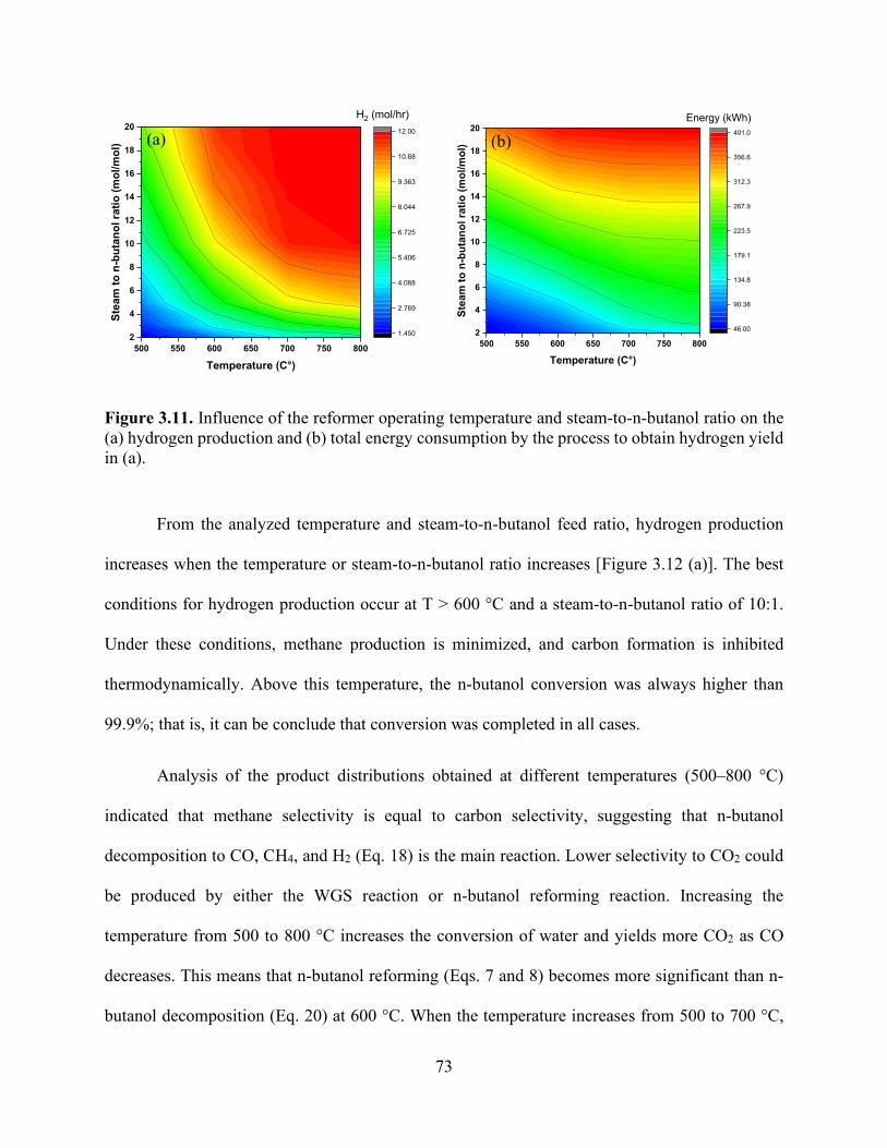
73
Figure 3.11. Influence of the reformer operating temperature and steam-to-n-butanol ratio on the (a) hydrogen production and (b) total energy consumption by the process to obtain hydrogen yield in (a).
From the analyzed temperature and steam-to-n-butanol feed ratio, hydrogen production
increases when the temperature or steam-to-n-butanol ratio increases [Figure 3.12 (a)]. The best
conditions for hydrogen production occur at T > 600 °C and a steam-to-n-butanol ratio of 10:1.
Under these conditions, methane production is minimized, and carbon formation is inhibited
thermodynamically. Above this temperature, the n-butanol conversion was always higher than
99.9%; that is, it can be conclude that conversion was completed in all cases.
Analysis of the product distributions obtained at different temperatures (500–800 °C)
indicated that methane selectivity is equal to carbon selectivity, suggesting that n-butanol
decomposition to CO, CH4, and H2 (Eq. 18) is the main reaction. Lower selectivity to CO2 could
be produced by either the WGS reaction or n-butanol reforming reaction. Increasing the
temperature from 500 to 800 °C increases the conversion of water and yields more CO2 as CO
decreases. This means that n-butanol reforming (Eqs. 7 and 8) becomes more significant than n-
butanol decomposition (Eq. 20) at 600 °C. When the temperature increases from 500 to 700 °C,
500 550 600 650 700 750 8002
4
6
8
10
12
14
16
18
20St
eam
to n
-but
anol
ratio
(mol
/mol
)
Temperature (C°)
1.450
2.769
4.088
5.406
6.725
8.044
9.363
10.68
12.00
H2 (mol/hr)
500 550 600 650 700 750 8002
4
6
8
10
12
14
16
18
20
Stea
m to
n-b
utan
ol ra
tio (m
ol/m
ol)
Temperature (C°)
46.00
90.38
134.8
179.1
223.5
267.9
312.3
356.6
401.0
Energy (kWh)
(a) (b)
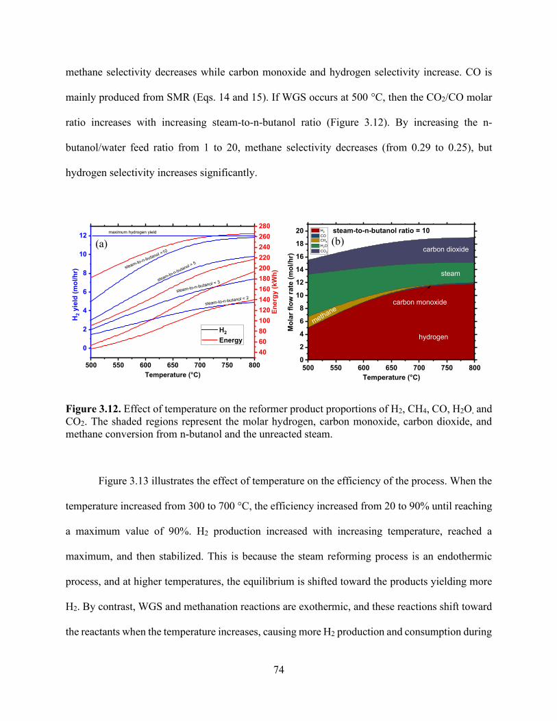
74
methane selectivity decreases while carbon monoxide and hydrogen selectivity increase. CO is
mainly produced from SMR (Eqs. 14 and 15). If WGS occurs at 500 °C, then the CO2/CO molar
ratio increases with increasing steam-to-n-butanol ratio (Figure 3.12). By increasing the n-
butanol/water feed ratio from 1 to 20, methane selectivity decreases (from 0.29 to 0.25), but
hydrogen selectivity increases significantly.
Figure 3.12. Effect of temperature on the reformer product proportions of H2, CH4, CO, H2O, and CO2. The shaded regions represent the molar hydrogen, carbon monoxide, carbon dioxide, and methane conversion from n-butanol and the unreacted steam.
Figure 3.13 illustrates the effect of temperature on the efficiency of the process. When the
temperature increased from 300 to 700 °C, the efficiency increased from 20 to 90% until reaching
a maximum value of 90%. H2 production increased with increasing temperature, reached a
maximum, and then stabilized. This is because the steam reforming process is an endothermic
process, and at higher temperatures, the equilibrium is shifted toward the products yielding more
H2. By contrast, WGS and methanation reactions are exothermic, and these reactions shift toward
the reactants when the temperature increases, causing more H2 production and consumption during
500 550 600 650 700 750 800
0
2
4
6
8
10
12
steam-to-n-butanol = 2
H2
Energy
H2 y
ield
(mol
/hr)
Temperature (°C)
steam-to-n-butanol = 3steam-to-n-butanol = 5steam-to-n-butanol =10
maximum hydrogen yield
406080100120140160180200220240260280
Ener
gy (k
Wh)
500 550 600 650 700 750 8000
2
4
6
8
10
12
14
16
18
20
Mol
ar fl
ow ra
te (m
ol/h
r)
Temperature (°C)
H2
CO CH4
H2O CO2
hydrogen
steam
methane
carbon dioxide
carbon monoxide
steam-to-n-butanol ratio = 10
(a) (b)
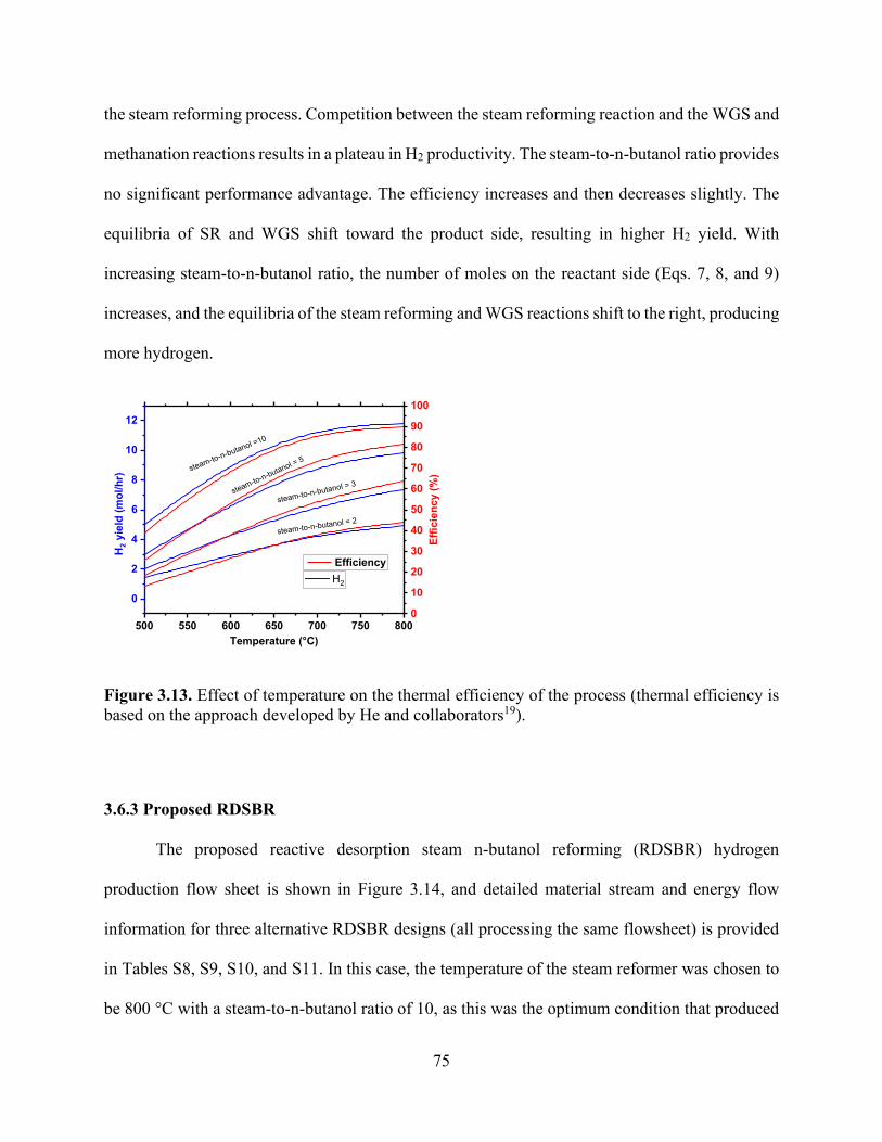
75
the steam reforming process. Competition between the steam reforming reaction and the WGS and
methanation reactions results in a plateau in H2 productivity. The steam-to-n-butanol ratio provides
no significant performance advantage. The efficiency increases and then decreases slightly. The
equilibria of SR and WGS shift toward the product side, resulting in higher H2 yield. With
increasing steam-to-n-butanol ratio, the number of moles on the reactant side (Eqs. 7, 8, and 9)
increases, and the equilibria of the steam reforming and WGS reactions shift to the right, producing
more hydrogen.
Figure 3.13. Effect of temperature on the thermal efficiency of the process (thermal efficiency is based on the approach developed by He and collaborators19).
3.6.3 Proposed RDSBR
The proposed reactive desorption steam n-butanol reforming (RDSBR) hydrogen
production flow sheet is shown in Figure 3.14, and detailed material stream and energy flow
information for three alternative RDSBR designs (all processing the same flowsheet) is provided
in Tables S8, S9, S10, and S11. In this case, the temperature of the steam reformer was chosen to
be 800 °C with a steam-to-n-butanol ratio of 10, as this was the optimum condition that produced
500 550 600 650 700 750 800
0
2
4
6
8
10
12
steam-to-n-butanol = 2
H2
H2 y
ield
(mol
/hr)
Temperature (°C)
steam-to-n-butanol = 3steam-to-n-butanol = 5
steam-to-n-butanol =10
0
10
20
30
40
50
60
70
80
90
100
Efficiency
Effic
ienc
y (%
)

76
the highest yield of hydrogen. Then, the regeneration stream from desorption was fixed as 0.5
mol/h n-butanol (with 3 mol/h N2), and the other 0.5 mol/h n-butanol was supplied from fresh feed.
One of the advantages of the novel process is improving the energy of the process to desorb n-
butanol and simultaneously make hydrogen. The application of product recovery through RD
demonstrated that significant improvement can be achieved. In this process, the steam reformer
harvests the energy from n-butanol desorption, which has nitrogen that enhances the reaction as
well as n-butanol supplied at an elevated temperature. To obtain a better understanding of the
process, the total energy consumption was divided into separate parts, thereby illustrating that the
energy consumed by the steam reformer feed heater dropped from a value of 114 kWh to a value
of 89 kWh for the case of coupling the desorber. An increase in the harvested energy can be
achieved by changing the ratio of n-butanol obtained from the desorption of the ABE stream to n-
butanol fresh feed. The calculation of results for SBR is first presented. The results exhibited
superior (in reducing specific energy consumption) performance to that of the steam n-butanol
reformer only. As indicated by the above analysis, more energy can be harvested in the RDSBR
process. This indicates that improved designs can potentially be developed by coupling the
desorption process with steam reforming.
Table 3.3. Performance Summary of Baseline SBR and Proposed RDSBR.
Performance summary
Baseline SBR (case a) Baseline SBR with heat integration (case b)
Proposed RDSBR
Cooler 1, kW 82 - - Cooler 2, kW 42 - - Cooler 3, kW 17 - - Reformer feed
heater, kW 263 114 89
Reformer, kW 151 151 151 Net power, MW 555 265 240

77
Figure 3.14. Specific power requirements for the n-butanol reforming process are divided into components (the orange color represents the cooling requirement, dark blue represents n-butanol feed heating, and dark red represents the reformer energy required to keep the temperature constant at 800 °C).
Base case integrated case desorptive reactor0
50100150200250300350400450500550600
Ener
gy R
equi
red
(kW
h/m
ol o
f n-b
utan
ol)
Cooling requirement Feed heating Reformer Energy

78
3.7 Conclusion
The intensification of an adsorption–desorption unit with an SBR process was investigated
through the implementation of a combined RD reforming reactor. An Aspen simulation model was
used for an intensified reactive desorber. The effect of varying temperature and steam injection on
product composition was investigated. The thermodynamic equilibrium of n-butanol reforming
was studied by employing Gibbs free energy minimization approach as a function of H2O:C4H9OH
ratio, CO2:C4H9OH ratio, and reforming temperature. At a reforming temperature of 800 °C, the
thermodynamic calculation result demonstrated good reaction performance within the region
studied. The two reaction processes were SBR with and without the coupling reactive desorber.
Favorable hydrogen production was obtained by using the scheme of a desorber with a steam
reformer. The hydrogen yield in both processes can be enhanced by adding more steam to the
reaction system. A comparison of the energy of the RDSBR process with that of an individual SBR
indicates that RDSBR is a more effective process. This process enables energy reduction by 9.4%
in hydrogen production. The study showed that integrating separation with an additional reaction
process (an intensified process) to generate more valuable products was attractive method that
improved efficiency and consequently costs. Process intensification based on these combinations
costs less because reactions was induced simultaneously with separation. This process was
beneficial because of its efficient energy and material utilization.

79
3.8 Appendix
Table 3.4. Energy Load information for Baseline Design of SBR (P=1 bar, T=500 °C) for 1 mol/h of initial n-butanal.
C₄H₁₀O(i) = 1 mol/h Heat Load (kJ/s) Inlet H2O (mol/h)
Outlet H2 (mol/h)
n-butanol feed heater
steam feed heater
reformer energy
Cooler 2
Cooler 3 Cooler 4
1 0.73 35.49 17.46 0.00 -11.55 -9.17 -2.87 2 1.71 35.49 35.49 0.00 -12.71 -12.33 -5.35 3 2.03 35.49 52.39 0.00 -13.09 -13.75 -5.08 5 2.39 35.49 87.32 0.00 -13.46 -16.20 -5.40
10 3.02 35.49 174.63 0.00 -14.43 -23.32 -7.60 15 3.57 35.49 261.95 0.00 -15.66 -30.86 -10.03 20 4.09 35.49 349.27 0.00 35.49 35.49 -12.51
Table 3.5. Energy Load information for Baseline Design of SBR (P=1 bar, T=600 °C) for 1 mol/h of initial n-butanal.
C₄H₁₀O(i) = 1 mol/h Heat Load (kJ/s) Inlet H2O (mol/h)
Outlet H2 (mol/h)
n-butanol feed heater
steam feed heater
reformer energy
Cooler 2
Cooler 3 Cooler 4
1 2.92 41.71 18.55 19.18 -16.59 -9.43 -2.86 2 4.32 41.71 37.10 34.08 -19.93 -13.68 -4.94 3 6.35 41.71 55.64 46.82 -23.14 -17.37 -7.89 5 9.23 41.71 92.74 67.98 -29.36 -23.11 -10.96 10 10.67 41.71 185.48 102.41 -44.17 -33.49 -12.40 20 11.36 41.71 278.22 119.19 -58.30 -41.35 -13.68
Table 3.6. Energy Load information for Baseline Design of SBR (P=1 bar, T=700 °C) for 1 mol/h of initial n-butanal.
C₄H₁₀O(i) = 1 mol/h Heat Load (kJ/s) Inlet H2O (mol/h)
Outlet H2 (mol/h)
n-butanol feed heater
steam feed heater
reformer energy Cooler 2 Cooler 3 Cooler 4
1 1.92 48.30 19.67 38.98 -24.19 -9.17 -2.84 2 4.36 48.30 39.34 82.76 -29.41 -13.00 -4.03 3 6.29 48.30 59.00 109.84 -34.24 -17.61 -5.85 5 9.08 48.30 98.34 134.38 -43.12 -26.41 -12.03 10 11.55 48.30 196.68 143.71 -63.45 -39.54 -16.58 15 11.87 48.30 295.02 141.65 -82.93 -46.59 -15.27 20 11.94 48.30 393.36 139.30 -102.12 -52.52 -16.00

80
Table 3.7. Energy Load information for Baseline Design of SBR (P=1 bar, T=800 °C).
C₄H₁₀O(i) = 1 mol/h Heat Load (kJ/s) Inlet H2O (mol/h)
Outlet H2 (mol/h)
n-butanol feed heater
steam feed heater
reformer energy Cooler 2 Cooler 3 Cooler 4
1 2.00 55.21 20.82 41.19 -31.87 -9.08 -2.84 2 4.92 55.21 41.65 55.21 -38.80 -12.12 -3.88 3 7.39 55.21 62.47 146.42 -45.37 -16.23 -5.10 5 9.82 55.21 104.11 158.06 -56.39 -27.51 -11.34
10 11.81 55.21 208.23 151.62 -82.23 -42.28 -17.71 15 11.95 55.21 312.34 146.84 -107.52 -49.74 -15.90 20 11.98 55.21 416.46 143.66 -132.57 -55.69 -16.31
Table 3.8. Equilibrium SBR Inlet and Outlet Conditions of reformer and WGS reactions (P=1 bar, T=500 °C) integrated case.
Inlet (mol/h) Outlet (mol/h) Heat Load (kJ/s) C₄H₁₀O H2O CO CH4 H2O CO2 H2 C₄H₁₀O reformer heater
1 2 0.050 2.625 0.300 1.325 1.451 5.11E-19 -6.60 40.05 1 3 0.020 2.491 1.002 1.489 2.017 1.65E-19 -0.28 53.21 1 5 0.013 2.248 2.509 1.739 2.995 3.77E-20 11.87 79.43 1 10 0.010 1.748 6.505 2.243 5.000 3.68E-21 37.44 145.06 1 15 0.009 1.350 10.708 2.641 6.592 6.67E-22 57.83 211.04 1 20 0.008 1.030 15.068 2.962 7.873 1.51E-22 74.20 277.35
Table 3.9. Equilibrium SBR for Inlet and Outlet Conditions of reformer and WGS reactions (P=1 bar, T=600 °C) integrated case.
Inlet (mol/h) Outlet (mol/h) Heat Load (kJ/s) C₄H₁₀O H2O CO CH4 H2O CO2 H2 C₄H₁₀O reformer heater
1 2 0.963 2.030 0.022 1.008 2.919 9.689E-19 34.08 37.62 1 3 0.572 1.779 0.130 1.649 4.313 3.052E-19 46.82 46.05 1 5 0.192 1.365 0.922 2.443 6.347 5.105E-20 67.98 66.85 1 10 0.051 0.681 4.413 3.268 9.226 1.511E-21 102.40 130.66 1 15 0.028 0.325 8.679 3.647 10.671 6.724E-23 119.19 198.00 1 20 0.019 0.157 13.333 3.824 11.353 3.856E-24 126.29 266.39

81
Table 3.10. Equilibrium SBR for Inlet and Outlet Conditions of reformer and WGS reactions (P=1 bar, T=700 °C) integrated case.
Inlet (mol/h) Outlet (mol/h) Heat Load (kJ/s) C₄H₁₀O H2O CO CH4 H2O CO2 H2 C₄H₁₀O reformer heater
1 2 2.369 1.317 0.003 0.314 4.362 5.75E-19 82.76 38.26 1 3 2.314 0.850 0.015 0.836 6.285 8.1E-20 109.84 46.05 1 5 1.408 0.379 0.166 2.213 9.076 3.23E-21 134.38 60.46 1 10 0.140 0.078 3.296 3.782 11.548 8.49E-24 143.70 118.63 1 15 0.040 0.025 8.089 3.936 11.861 1.18E-25 141.65 189.78 1 20 0.021 0.010 13.042 3.968 11.938 4.24E-27 139.30 260.32
Table 3.11. Equilibrium SBR Inlet and Outlet Conditions reformer and WGS reactions (P=1 bar, T=800 °C) integrated case.
Inlet (mol/h) Outlet (mol/h) Heat Load (kJ/s) C₄H₁₀O H2O CO CH4 H2O CO2 H2 C₄H₁₀O reformer heater
1 2 2.919 1.040 0.000 0.040 4.919 5.99E-19 101.22 39.01 1 3 3.392 0.306 0.004 0.302 7.385 7.73E-21 146.42 47.20 1 5 2.011 0.043 0.098 1.946 9.816 1.17E-23 158.06 59.35 1 10 0.166 0.006 3.178 3.828 11.809 1.27E-26 151.62 114.39 1 15 0.042 0.002 8.046 3.956 11.950 1.92E-28 146.84 185.62 1 20 0.022 0.001 13.024 3.977 11.975 7.96E-30 256.41 143.65
Table 3.12. Base Case Material and Energy Stream Information.
Stream name T (°C) C₄H₁₀O (mol/h)
CO (mol/h)
CO2 (mol/h)
H2O (mol/h)
H2 (mol/h)
CH4 (mol/h)
C₄H₁₀O feed 307.6 1 0 0 0 0 0 steam feed 307.6 0 0 0 10 0 0
reformer feed 800 1 0 0 10 0 0 reformer outlet 800 0 2.452 1.542 5.465 9.523 0.006 HT WGS outlet 438.15 0.971 3.023 3.983 11.004 0.006 LT WGS outlet 251.06 0.160 3.833 3.173 11.815 0.006 Stream name Energy Flow (kJ/s)
n-butanol feed heater 55.21
steam feed heater 208.23 Reformer duty 151.62
Cooler 2 -82.23 Cooler 3 -42.28 Cooler 4 -17.71

82
Table 3.13. Integrated Case Material and Energy Stream Information.
Stream name T (°C) C₄H₁₀O (mol/h)
CO (mol/h)
CO2 (mol/h)
H2O (mol/h)
H2 (mol/h)
CH4 (mol/h)
C₄H₁₀O feed 307.6 1 0 0 0 0 0 steam feed 307.6 0 0 0 10 0 0
reformer feed 800 1 0 0 10 0 0 reformer outlet 800 0 2.452 1.542 5.465 9.523 0.006 HT WGS inlet 320 0 2.452 1.542 5.465 9.523 0.006
HT WGS outlet 416.08 0 0.855 3.139 3.867 11.120 0.006 LT WGS inlet 210 0 0.855 3.139 3.867 11.120 0.006
LT WGS outlet 251.06 0 0.166 3.828 3.178 11.809 0.006 LT WGS outlet
cooled 110 0 0.166 3.828 3.178 11.809 0.006 Stream name Energy Flow (kJ/s)
Reformer feed heater 114.39 Reformer duty 151.62
Table 3.14. Reactive Desorption Case Material and Energy Stream Information.
Stream name T (°C) C₄H₁₀O (mol/h)
CO (mol/h)
CO2 (mol/h)
H2O (mol/h)
H2 (mol/h)
CH4 (mol/h)
N2 (mol/h)
C₄H₁₀O fresh feed 307.6 0.5 0 0 0 0 0 0 C₄H₁₀O feed from desorption 450 0.5 0 0 0 0 0 3 steam feed 307.6 0 0 0 10 0 0 0 reformer feed 800 1 0 0 10 0 0 3 reformer outlet 800 0 2.454 1.542 5.463 9.527 0.005 3 HT WGS inlet 320 0 2.454 1.542 5.463 9.527 0.005 3 HT WGS outlet 406.8 2.454 1.542 5.463 9.527 0.005 3 LT WGS inlet 210 0 0.807 3.188 3.817 11.174 0.005 3 LT WGS outlet 246.3 0.149 3.846 3.158 11.832 0.005 3 LT WGS outlet cooled 110 0 0.149 3.846 3.158 11.832 0.005 3 Stream name Energy Flow (kJ/s) Reformer feed heater 89.42 Reformer duty 151.62

83
3.9 References
1. Owusu, P. A.; Asumadu-Sarkodie, S. A Review of Renewable Energy Sources, Sustainability
Issues and Climate Change Mitigation. Cogent Eng. 2016, 3 (1), 1167990.
https://doi.org/10.1080/23311916.2016.1167990.
2. Asif, M.; Muneer, T. Energy Supply, Its Demand and Security Issues for Developed and
Emerging Economies. Renew. Sustain. Energy Rev. 2007, 11 (7), 1388–1413.
https://doi.org/10.1016/j.rser.2005.12.004.
3. Corma, A.; Iborra, S.; Velty, A. Chemical Routes for the Transformation of Biomass into
Chemicals. Chem. Rev. 2007, 107 (6), 2411–2502. https://doi.org/10.1021/cr050989d.
4. Werpy, T.; Petersen, G. Top Value Added Chemicals from Biomass: Volume I -- Results of
Screening for Potential Candidates from Sugars and Synthesis Gas; United States, 2004.
https://doi.org/10.2172/15008859.
5. IEA; Eisentraut, A.; Brown, A. Technology Roadmap: Bioenergy for Heat and Power. Manag.
Environ. Qual. An Int. J. 2012, 24 (1), 1–41. https://doi.org/10.1108/meq.2013.08324aaa.005.
6. Huber, G. W.; Iborra, S.; Corma, A. Synthesis of Transportation Fuels from Biomass:
Chemistry, Catalysts, and Engineering. Chem. Rev. 2006, 106 (9), 4044–4098.
https://doi.org/10.1021/cr068360d.
7. Nanda, S.; Azargohar, R.; Dalai, A. K.; Kozinski, J. A. An Assessment on the Sustainability
of Lignocellulosic Biomass for Biorefining. Renew. Sustain. Energy Rev. 2015, 50, 925–941.
8. Foust, T. D.; Aden, A.; Dutta, A.; Phillips, S. An Economic and Environmental Comparison
of a Biochemical and a Thermochemical Lignocellulosic Ethanol Conversion Processes.
Cellulose 2009, 16 (4), 547–565. https://doi.org/10.1007/s10570-009-9317-x.
9. Ezeji, T. C.; Qureshi, N.; Blaschek, H. P. Butanol Fermentation Research: Upstream and
84
Downstream Manipulations. Chem. Rec. 2004, 4 (5), 305–314.
https://doi.org/10.1002/tcr.20023.
10. Oudshoorn, A.; Van Der Wielen, L. A. M.; Straathof, A. J. J. Assessment of Options for
Selective 1-Butanol Recovery from Aqueous Solution. Ind. Eng. Chem. Res. 2009, 48 (15),
7325–7336. https://doi.org/10.1021/ie900537w.
11. Qureshi, N.; Hughes, S.; Maddox, I. S.; Cotta, M. A. Energy-Efficient Recovery of Butanol
from Model Solutions and Fermentation Broth by Adsorption. Bioprocess Biosyst. Eng. 2005,
27 (4), 215–222. https://doi.org/10.1007/s00449-005-0402-8.
12. Bonenfant, D.; Kharoune, M.; Niquette, P.; Mimeault, M.; Hausler, R. Advances in Principal
Factors Influencing Carbon Dioxide Adsorption on Zeolites. Sci. Technol. Adv. Mater. 2008,
9 (1), 13007. https://doi.org/10.1088/1468-6996/9/1/013007.
13. Chen, Z.; Po, F.; Grace, J. R.; Jim Lim, C.; Elnashaie, S.; Mahecha-Botero, A.; Rakib, M.;
Shirasaki, Y.; Yasuda, I. Sorbent-Enhanced/Membrane-Assisted Steam-Methane Reforming.
Chem. Eng. Sci. 2008, 63 (1), 170–182.
https://doi.org/https://doi.org/10.1016/j.ces.2007.09.031.
14. Wang, W.; Cao, Y. Hydrogen Production via Sorption Enhanced Steam Reforming of Butanol:
Thermodynamic Analysis. Int. J. Hydrogen Energy 2011, 36 (4), 2887–2895.
https://doi.org/https://doi.org/10.1016/j.ijhydene.2010.11.110.
15. Nahar, G. A.; Madhani, S. S. Thermodynamics of Hydrogen Production by the Steam
Reforming of Butanol: Analysis of Inorganic Gases and Light Hydrocarbons. Int. J. Hydrogen
Energy 2010, 35 (1), 98–109. https://doi.org/https://doi.org/10.1016/j.ijhydene.2009.10.013.
16. Bimbela, F.; Oliva, M.; Ruiz, J.; García, L.; Arauzo, J. Catalytic Steam Reforming of Model
Compounds of Biomass Pyrolysis Liquids in Fixed Bed: Acetol and n-Butanol. J. Anal. Appl.
85
Pyrolysis 2009, 85 (1), 204–213. https://doi.org/https://doi.org/10.1016/j.jaap.2008.11.033.
17. Wang, W.; Cao, Y. Hydrogen-Rich Gas Production for Solid Oxide Fuel Cell (SOFC) via
Partial Oxidation of Butanol: Thermodynamic Analysis. Int. J. Hydrogen Energy 2010, 35
(24), 13280–13289. https://doi.org/https://doi.org/10.1016/j.ijhydene.2010.09.031.
18. Wang, W. Hydrogen Production via Dry Reforming of Butanol: Thermodynamic Analysis.
Fuel 2011, 90 (4), 1681–1688. https://doi.org/10.1016/j.fuel.2010.11.001.
19. He, L.; Parra, J. M. S.; Blekkan, E. A.; Chen, D. Towards Efficient Hydrogen Production from
Glycerol by Sorption Enhanced Steam Reforming. Energy Environ. Sci. 2010, 3 (8), 1046–
1056. https://doi.org/10.1039/B922355J.
20. Hartley, U. W.; Amornraksa, S.; Kim-Lohsoontorn, P.; Laosiripojana, N. Thermodynamic
Analysis and Experimental Study of Hydrogen Production from Oxidative Reforming of N-
Butanol. Chem. Eng. J. 2015, 278, 2–12. https://doi.org/10.1016/j.cej.2015.02.016.
21. Huber, G. W.; Dumesic, J. A. An Overview of Aqueous-Phase Catalytic Processes for
Production of Hydrogen and Alkanes in a Biorefinery. Catal. Today 2006, 111 (1–2), 119–
132. https://doi.org/10.1016/j.cattod.2005.10.010.
22. Agrimi; Alexopoulou, E.; Bartzoka, E. D.; Buonerba, A.; Cavani, F.; Christou, M.; Colucci,
A.; Couturier, J.-L.; Crestini, C.; Dubois, J.-L. Biorefineries: An Introduction; Walter de
Gruyter GmbH & Co KG, 2015.
23. Saravanan, V.; Waijers, D. A.; Ziari, M.; Noordermeer, M. A. Recovery of 1-Butanol from
Aqueous Solutions Using Zeolite ZSM-5 with a High Si/Al Ratio; Suitability of a Column
Process for Industrial Applications. Biochem. Eng. J. 2010, 49 (1), 33–39.
https://doi.org/https://doi.org/10.1016/j.bej.2009.11.008.
24. Oudshoorn, A.; van der Wielen, L. A. M.; Straathof, A. J. J. Desorption of Butanol from Zeolite

86
Material. Biochem. Eng. J. 2012, 67, 167–172. https://doi.org/10.1016/j.bej.2012.06.014.
25. Thomas, W. J.; Crittenden, B. The Development of Adsorption Technology; Butterworth-
Heinemann, 1998. https://doi.org/10.1016/b978-075061959-2/50002-1.
26. Mallon, E. E.; Babineau, I. J.; Kranz, J. I.; Guefrachi, Y.; Siepmann, J. I.; Bhan, A.; Tsapatsis,
M. Correlations for Adsorption of Oxygenates onto Zeolites from Aqueous Solutions. J. Phys.
Chem. B 2011, 115 (39), 11431–11438. https://doi.org/10.1021/jp208143t.
27. Koble, R. A.; Corrigan, T. E. Adsorption Isotherms for Pure Hydrocarbons. Ind. Eng. Chem.
1952, 44 (2), 383–387.
28. Dąbrowski, A. Adsorption—from Theory to Practice. Adv. Colloid Interface Sci. 2001, 93 (1–
3), 135–224.
29. Chapter 12 The Use of Adsorption Methods for the Assessment of the Surface Area and Pore
Size Distribution of Heterogeneous Catalysts. In Catalysis; Moulijn, J. A., van Leeuwen, P.
W. N. M., van Santen, R. A. B. T.-S. in S. S. and C., Eds.; Elsevier, 1993; Vol. 79, pp 419–
438. https://doi.org/https://doi.org/10.1016/S0167-2991(08)63816-1.
30. Langmuir, I. THE ADSORPTION OF GASES ON PLANE SURFACES OF GLASS, MICA
AND PLATINUM. J. Am. Chem. Soc. 1918, 40 (9), 1361–1403.
https://doi.org/10.1021/ja02242a004.
31. Freundlich, H. Über Die Adsorption in Lösungen. Zeitschrift für Physikalische Chemie. 1907,
p 385. https://doi.org/10.1515/zpch-1907-5723.
32. Sutton, D.; Kelleher, B.; Ross, J. R. H. Review of Literature on Catalysts for Biomass
Gasification. Fuel Process. Technol. 2001, 73 (3), 155–173. https://doi.org/10.1016/S0378-
3820(01)00208-9.
33. Sun, J.; Wang, Y. Recent Advances in Catalytic Conversion of Ethanol to Chemicals. ACS

87
Catal. 2014, 4 (4), 1078–1090.
34. Lima da Silva, A.; Müller, I. L. Hydrogen Production by Sorption Enhanced Steam Reforming
of Oxygenated Hydrocarbons (Ethanol, Glycerol, n-Butanol and Methanol): Thermodynamic
Modelling. Int. J. Hydrogen Energy 2011, 36 (3), 2057–2075.
https://doi.org/https://doi.org/10.1016/j.ijhydene.2010.11.051.
35. Brauer, H.; Varma, Y. B. G. Design and Operation of Adsorption Equipment BT - Air
Pollution Control Equipment; Brauer, H., Varma, Y. B. G., Eds.; Springer Berlin Heidelberg:
Berlin, Heidelberg, 1981; pp 307–333. https://doi.org/10.1007/978-3-642-67905-6_10.
36. Perry, J. H. Chemical Engineers’ Handbook. ACS Publications 1950.
37. Worch, E. Adsorption Technology in Water Treatment; De Gruyter, 2012.
https://doi.org/10.1515/9783110240238.
38. Goerlitz, R.; Weisleder, L.; Wuttig, S.; Trippel, S.; Karstens, K.; Goetz, P.; Niebelschuetz, H.
Bio-Butanol Downstream Processing: Regeneration of Adsorbents and Selective Exclusion of
Fermentation by-Products. Adsorption 2018, 24 (1), 95–104. https://doi.org/10.1007/s10450-
017-9918-x.
39. Raganati, F.; Procentese, A.; Olivieri, G.; Russo, M. E.; Salatino, P.; Marzocchella, A. Bio-
Butanol Separation by Adsorption on Various Materials: Assessment of Isotherms and Effects
of Other ABE-Fermentation Compounds. Sep. Purif. Technol. 2018, 191, 328–339.
https://doi.org/10.1016/j.seppur.2017.09.059.
40. Van der Perre, S.; Gelin, P.; Claessens, B.; Martin-Calvo, A.; Cousin Saint Remi, J.; Duerinck,
T.; Baron, G. V.; Palomino, M.; Sánchez, L. Y.; Valencia, S.; et al. Intensified Biobutanol
Recovery by Using Zeolites with Complementary Selectivity. ChemSusChem 2017, 10 (14),
2968–2977. https://doi.org/10.1002/cssc.201700667.

88
41. Nguyen, C. M.; Reyniers, M. F.; Marin, G. B. Adsorption Thermodynamics of C1-C4 Alcohols
in H-FAU, H-MOR, H-ZSM-5, and H-ZSM-22. J. Catal. 2015, 322, 91–103.
https://doi.org/10.1016/j.jcat.2014.11.013.
42. Nguyen, C. M.; Reyniers, M. F.; Marin, G. B. Theoretical Study of the Adsorption of C1-C4
Primary Alcohols in H-ZSM-5. Phys. Chem. Chem. Phys. 2010, 12 (32), 9481–9493.
https://doi.org/10.1039/c000503g.
43. Van Der Mynsbrugge, J.; Hemelsoet, K.; Vandichel, M.; Waroquier, M.; Van Speybroeck, V.
Efficient Approach for the Computational Study of Alcohol and Nitrile Adsorption in H-ZSM-
5. J. Phys. Chem. C 2012, 116 (9), 5499–5508. https://doi.org/10.1021/jp2123828.
44. Adhikari, S.; Fernando, S.; Gwaltney, S. R.; Filip To, S. D.; Mark Bricka, R.; Steele, P. H.;
Haryanto, A. A Thermodynamic Analysis of Hydrogen Production by Steam Reforming of
Glycerol. Int. J. Hydrogen Energy 2007, 32 (14), 2875–2880.
https://doi.org/10.1016/j.ijhydene.2007.03.023.

89
Chapter 4: Sensitivity Analysis of an Intensified CO2 Mineralization-based Scheme and RO Desalination Process in Ca2+/Mg2+-Rich Aqueous Solutions for CO2 Management
4.1 Abstract
A CO2 capture process which is based on the use of MEA absorption was simulated using
Aspen Plus and compared with proposed CO2 mineralization in Ca2+/Mg2+-rich aqueous solutions
that enable carbon capture. This paper proposes two baseline reference CO2-capturing
technologies: conventional carbon capture and storage technology (CCS) and CO2 mineralization
technology. For sensitivity analysis, simulations were conducted that kept all parameters constant
except for the studied parameter to evaluate the degree to which economic feasibility was
influenced by the studied parameter. A process design that achieved maximum CO2 utilization was
considered as the base case in which all of the used CO2 was converted to carbonates, MgCO3,
CaCO2, and NaHCO3. Here, we propose integrating CO2 mineralization and RO desalination
pretreatment into a single process as a potential approach to enhance the efficiency and energy
utilization of CO2 capture. This study proposes a calcium and magnesium production process that
involves injecting low-concentration CO2 (8–15 vol %) from flue gas into a carbonation process
in a desalination plant. The feasibility of the overall process was analyzed by calculating the energy
required for a standalone desalination pretreatment process and a standalone CO2 mineralization
process to the hybrid process.
90
4.2 Introduction
Anthropogenic emission of CO2, mainly induced by fossil fuel combustion, contributes to
CO2 accumulation in the atmosphere. In 2004, global CO2 emissions were 27.4 Gt and have been
increasing dramatically since then, reaching 33.4 Gt in 2016. Consequently, mitigation efforts to
achieve atmospheric CO2 concentration stabilization at 500 ppm are needed.1 Different
geoengineering techniques have been proposed for the direct decarbonization of the global
atmosphere, each with different costs and environmental consequences.2 The large scale of CCS
suggests a combination of different techniques would be most practical.3
Mineral carbonation has been emerging as a potential carbon capture, utilization, and
storage technology solution to sequester CO2 from medium-size emitters when geological
sequestration is not a viable option. These processes offer a leakage-free alternative to geological
storage of CO2 and represent an environmentally friendly process that requires little effort to
monitor. In this process, CO2 is chemically reacted with sodium-, calcium-, and magnesium-
containing materials to form stable carbonates.4 The mineralized carbon can then be disposed of
at the Earth’s surface. The large carbon storage capacity, minimal environmental impact, and low
risk of late CO2 release suggest the viability of the proposed scheme as a primary means of long-
term Gt-scale CO2 waste management.
Initially, CO2 mineralization was developed by the reaction between CO2 and natural
alkaline silicate ores, such as serpentine [Mg3Si2O5(OH)4],4–7 wollastonite (CaSiO3),8–12 olivine
[(Fex,Mg1-x)2SiO4],13–16 dolomite,10,17–19 and albite.20 Mineral carbonation of Mg-Ca-Fe-silicates
has high carbonation potential (>10,000 Gt C)21 and typically requires 2 tons of silicate mineral
per ton of CO2 capture. A carbonation reaction occurs when a metal oxide such as calcium oxide
or magnesium oxide reacts with CO2 to yield calcium or magnesium carbonate.

91
CaO + CO2 → CaCO3 ΔH = −179 (KJ/mol) (1)
MgO + CO2 → MgCO3 ΔH = −118 (KJ/mol) (2)
Olivine (forsterite)
Mg2SiO4 + 2CO2 → 2MgCO3 + SiO2 ΔH = −89 (KJ/mol) (3)
Wollastonite
CaSiO3 + CO2 → CaCO3 + SiO2 ΔH = −87 (KJ/mol) (4)
Serpentine
Mg3Si2O5(OH)4 + 3CO2 → 3MgCO3 + 2SiO2 + 2H2O ΔH = −64 (KJ/mol) (5)
Although these approaches can stably store CO2 for thousands of years, their low reaction
rate and high energy consumption limit the application of these methods in industrial
implementation, which entails large-scale mining and disposal operations. For example, an 18
ton/day mining operation would be able to capture 18 Mt of CO2 per year, enough to serve roughly
five 500-MWe-fired power stations.22
Apart from mining-based applications, alkaline waste from various industrial applications
is used as feedstock in CO2 mineral carbonation. Recent studies have demonstrated an ability to
improve the mineralization process using natural minerals and solid waste.8,23–26 Kodama et al.27
used steelmaking slag and ammonium chloride solution to convert CO2 to CaCO3. Nduagu et al.28
used magnesium silicates and ammonium sulfate to produce magnesium hydroxide that absorbs
CO2 and produces MgCO3. Xie et al.29,30 used phosphogypsum waste, magnesium chloride, and
potash feldspar to mineralize CO2 and produce valuable products. Although quantities of waste
are not available at the Gt scale for a mineral carbonation feedstock, the quantities are still
substantial enough to warrant integration in industries that produce the waste to reduce emissions.
These wastes contain a significant amount of calcium oxide or hydroxide (15% for concrete waste,

92
40% for steel slag). Many of these waste products have reusable values of 5–10 ($/ton), making
them comparable to or possibly higher than the expected cost of natural mineral feedstock. These
processes use less energy and produce higher value–added products. Energy and cost of solid
alkaline materials are primarily dependent on the plant’s scale, operating conditions, and operation
modulus, including pretreatments such as grinding, thermal activation, and product disposal.31,32
A multiwaste treatment integration approach is implemented using CO2 in the flue gas as a
chemical stabilizer for active components in alkaline solid wastes. From an economic perspective,
the carbonation reaction reduces the treatment cost associated with wastewater and increases the
value of alkaline solid waste simultaneously. Energy-intensive processes associated with feedstock
preparation, including process heating and slurry stirring, can be compensated by the exothermic
carbonation process, making the process economically viable.33
Aqueous sources such as seawater, subsurface brine, and industrial effluents are also
Mg2+/Ca2+-rich aqueous solutions and can potentially be applied for CO2 mineralization.34,35 In this
process, CO2 is transformed into carbonate precipitates and permanently stored as value-added
products.36 Wastewater or brine solution could be used as a liquid agent in the carbonation
reaction.37,38
Oil-field brine is another significant waste from oil and gas production, which is mainly
disposed of.39 In the United States, 18 billion barrels (2.12 billion m3) are produced yearly.40 The
primary disposal strategy for about 65% of this water is reinjection, which costs between $0.015
and $3 per barrel.41 Consequently, the management and disposal of oil-field brine costs $1.5 billion
per year in the United States.
Some brine has high concentrations of Ca, Mg, and Fe, which react with CO2 to form
CaCO3(s), MgCO2(s), and FeCO3(s) and other products under favorable conditions.42 Together,
93
these suggest the possibility of using the cations in saline wastewater and subsurface brine as
potential sources for CO2 mineralization to form carbonates.
Motivated by the current status of CO2 utilization technologies, this study proposes a
calcium and magnesium production process that involves injecting low-concentration CO2 (8–15
vol %) from flue gas into a carbonation process in a desalination plant. The feasibility of the overall
process is analyzed by calculating the energy required for a standalone desalination pretreatment
process and a standalone CO2 mineralization process to the hybrid process. Previous experiments
demonstrated that seawater is a viable option for precipitating 90% of Ca and Mg ions in seawater,
which is equivalent to 0.06 mol of CO2 that can be captured per liter in the natural seawater process.
Additionally, two to three times higher CO2 fixation potential could be achieved with more
concentrated water.43 Valuable by-products, such as magnesite and strontianite, can be precipitated
to reduce the operating cost of oil production.
4.3 Process Modeling and Simulation
4.3.1 Overall Description
Aspen Plus was used as the main simulator because necessary chemical units are available
from its library, and eRNTL was selected as the thermodynamic property method.44 The method
considers Hilgard thermodynamics, CO2 MEA reaction kinetics, and other mass transfer
phenomena associated with system mixture. The model explicitly accounts for solution chemistry,
which includes dissociations of H2O, NaOH, CaCl2, and CO2; the formation of bicarbonate; and
precipitation of calcium carbonate.
The main design schemes of the model include the following:

94
• CO2 mineralization plant (Baseline)
• CO2 amine-capture unit (Baseline)
• The advanced process to reduce power consumption baseline
4.3.2 Thermodynamic Framework
4.3.2.1 CO2 Amine-Capture Unit
The adsorption process was described by the zwitterion mechanism, is followed by the
hydration of CO2 to form HCO3−/CO3
2−, and is supplemented by the hydrolysis of carbamate as
shown in equations 6 and 7.
𝐶𝐶𝑂𝑂2 + 𝑅𝑅𝑁𝑁𝐻𝐻2 ⇌ 𝑅𝑅𝑁𝑁𝐻𝐻2+𝐶𝐶𝑂𝑂𝑂𝑂− (6)
𝑅𝑅𝑁𝑁𝐻𝐻2+𝐶𝐶𝑂𝑂𝑂𝑂− + 𝑅𝑅𝑁𝑁𝐻𝐻2 ⇌ 𝑅𝑅𝑁𝑁𝐻𝐻𝐶𝐶𝑂𝑂𝑂𝑂− + 𝑅𝑅𝑁𝑁𝐻𝐻2+ (7)
Performing CO2 desorption through a heating process of the MEA solution that is saturated
with CO2 to perform the reverse process of absorption.
𝐶𝐶𝑂𝑂32− + 2𝐻𝐻+ ℎ𝑒𝑒𝑎𝑎𝑎𝑎𝑎𝑎𝑎𝑎𝑒𝑒�⎯⎯⎯⎯�𝐶𝐶𝑂𝑂2(𝑔𝑔) + 𝐻𝐻2𝑂𝑂 (8)
𝐻𝐻𝐶𝐶𝑂𝑂3− + 𝐻𝐻+ ℎ𝑒𝑒𝑎𝑎𝑎𝑎𝑎𝑎𝑎𝑎𝑒𝑒�⎯⎯⎯⎯�𝐶𝐶𝑂𝑂2(𝑔𝑔) + 𝐻𝐻2𝑂𝑂 (9)
2𝐻𝐻𝐶𝐶𝑂𝑂3− + 𝑅𝑅𝑁𝑁𝐻𝐻2+ℎ𝑒𝑒𝑎𝑎𝑎𝑎𝑎𝑎𝑎𝑎𝑒𝑒�⎯⎯⎯⎯�𝑅𝑅𝑁𝑁𝐻𝐻𝐶𝐶𝑂𝑂𝑂𝑂− + 𝐶𝐶𝑂𝑂2(𝑔𝑔) + 𝐻𝐻2𝑂𝑂 (10)

95
4.3.2.2 CO2 Absorption Using Alkaline
CO2 reacts with brine metal cations to form carbonate precipitates through the following
reaction sequence. The aqueous solution is first brought into contact with the flow of flue gas in a
contactor where it takes up CO2. To promote mineral carbonate precipitation, precipitation of
calcium carbonate requires the speciation of aqueous CO2 to CO32−.
𝐶𝐶𝑂𝑂32− + 𝐻𝐻2𝑂𝑂 ⇌ 𝐻𝐻𝐶𝐶𝑂𝑂3− + 𝐻𝐻+ (11)
𝐻𝐻𝐶𝐶𝑂𝑂3− + 𝐻𝐻+ ⇌ 𝐶𝐶𝑂𝑂32− + 𝐻𝐻2𝑂𝑂 (12)
𝐶𝐶𝑂𝑂2 + 𝑂𝑂𝐻𝐻− ⇌ 𝐻𝐻𝐶𝐶𝑂𝑂3− (13)
𝐻𝐻𝐶𝐶𝑂𝑂3− ⇌ 𝐶𝐶𝑂𝑂2 + 𝑂𝑂𝐻𝐻− (14)
𝐻𝐻+ + 𝑂𝑂𝐻𝐻− ⇌ 𝐻𝐻2𝑂𝑂 (15)
𝐻𝐻𝐶𝐶𝑂𝑂3− + 𝑂𝑂𝐻𝐻− ⇌ 𝐶𝐶𝑂𝑂32− + 𝐻𝐻2𝑂𝑂 (16)
𝐶𝐶𝑎𝑎2+ + 𝐶𝐶𝑂𝑂32− ⇌ 𝐶𝐶𝑎𝑎𝐶𝐶𝑂𝑂3 (17)
𝐶𝐶𝑎𝑎𝐶𝐶𝑂𝑂3 + 𝐻𝐻+ ⇌ 𝐶𝐶𝑎𝑎2+ + 𝐻𝐻𝐶𝐶𝑂𝑂3− (18)
The pH determines the steps that control sequence of the reaction and the proportions of
carbonate species. At low pH of approximately 4, production of H2CO3 dominates; at mid pH of
around 6, HCO3− production dominates; then when the pH increases to a higher level around 9,
CO32− dominates.37 Therefore, precipitation of calcium carbonate is predominant at a basic pH
because of the carbonate ions that are available. Conversely, carbonate dissociates as a solution
and becomes more acidic. Several factors affect the efficiency of carbonate-forming processes,
such as brine composition, temperature, pressure, and pH. The purpose of this study was to
optimize the process conditions that form mineral carbonates using Aspen Plus by changing
temperature, pH, and solution composition. This study can help to determine the relationship
between aqueous solution composition and the formation of precipitates.

96
4.4 Results and Discussion
4.4.1 Base Case
4.4.1.1 CO2 Capture and Sequestration
A traditional CO2-removing unit process flow sheet is shown in Figure 4.1. The baseline
consists of the following building blocks: amine absorber, stripper, cooler. Clean flue gas is
extracted from the top of the absorber while the rich solvent stream is extracted from the bottom.45–
47 The rich amine is pumped through a lean/rich heat exchanger to recover the heat from incoming
lean amine. Afterward, additional heat is provided by the stripper reboiler to release CO2 from a
liquid solvent. The CO2-lean stream is pumped to the main heat exchanger to recover heat from
the incoming CO2-rich amine and then cooled and recycled to the absorber.45–47 The reboiler heats
rich amine to an appropriate temperature to break the chemical bonds and deliver a vapor stream
that acts as a stripping fluid. The overhead condenser provides a reflux liquid stream to the column
and purifies the CO2-rich gas as much as possible. The CO2-rich gas released from the stripper is
finally compressed and sent for storage.

97
4.4.1.1.1 Model Description
A CO2 capture plant was simulated in this work using Aspen Plus. The operating conditions
are presented in Table 4.1. The simulation was modeled using an electrolyte non-random two-
liquid (NRTL) property package.44
Table 4.1. Breakdown of specific power requirements represented in Figure 4.1.
Component Power Consumption (MWh/t of CO2) Recycle pumping 0.05 CO2 compression 0.22
Heating requirement 0.25 Cooling requirement 0.25
Work was calculated by summing work from heating, cooling, and compression. The
energy required for CO2 capture was based on the sum of the minimum energy required for CO2
capture using amine, which is 1.26 MWh per t of CO2, and additional energy for CO2 sequestration,
here estimated as 0.22 MWh per t of CO2: the energy needed to pressurize a 100% CO2 gaseous
stream from atmospheric pressure to 14 MPa. The primary energy consumers were compression
and heating48 (Table 4.1). Additional energy can be reduced to lower the energy of CO2 capture to
0.5 MWh per t of CO2 by maximizing heat integration between the lean–rich heat exchanger and
reducing the energy in the reboiler through heat integration.
Power demand was estimated using a four-stage centrifugal compressor with interstage
coolers on the basis of Dresser-Rand data. CO2 compression is an auxiliary load; the effect of the
pressure requirement should be specified on the basis of pressure for pipeline transport customers.
The majority of the captured CO2 must be sequestered, and a fraction of the captured CO2 can be
used as raw material for manufacturing and producing polymers and liquid fuels.49 The energy
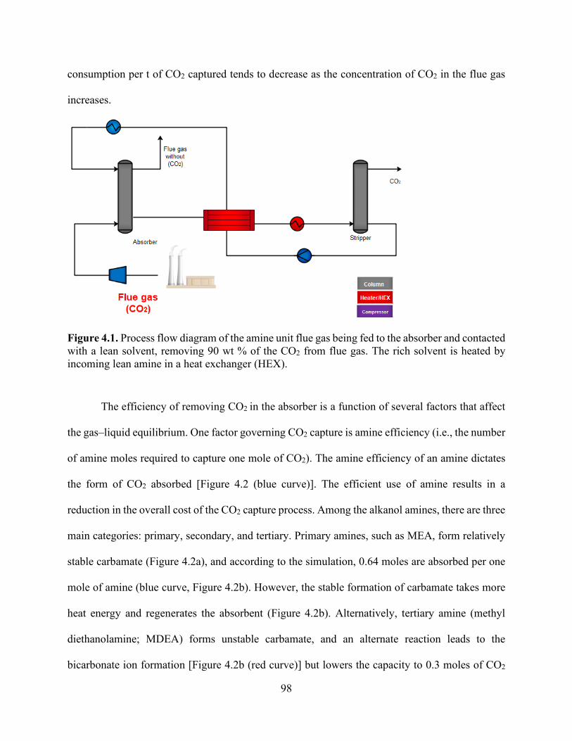
98
consumption per t of CO2 captured tends to decrease as the concentration of CO2 in the flue gas
increases.
Figure 4.1. Process flow diagram of the amine unit flue gas being fed to the absorber and contacted with a lean solvent, removing 90 wt % of the CO2 from flue gas. The rich solvent is heated by incoming lean amine in a heat exchanger (HEX).
The efficiency of removing CO2 in the absorber is a function of several factors that affect
the gas–liquid equilibrium. One factor governing CO2 capture is amine efficiency (i.e., the number
of amine moles required to capture one mole of CO2). The amine efficiency of an amine dictates
the form of CO2 absorbed [Figure 4.2 (blue curve)]. The efficient use of amine results in a
reduction in the overall cost of the CO2 capture process. Among the alkanol amines, there are three
main categories: primary, secondary, and tertiary. Primary amines, such as MEA, form relatively
stable carbamate (Figure 4.2a), and according to the simulation, 0.64 moles are absorbed per one
mole of amine (blue curve, Figure 4.2b). However, the stable formation of carbamate takes more
heat energy and regenerates the absorbent (Figure 4.2b). Alternatively, tertiary amine (methyl
diethanolamine; MDEA) forms unstable carbamate, and an alternate reaction leads to the
bicarbonate ion formation [Figure 4.2b (red curve)] but lowers the capacity to 0.3 moles of CO2

99
per mole of amine. Based on this analysis, MEA was chosen as a solvent due to low energy
consumption.
(a) (b)
Figure 4.2. CO2 absorption isotherm for (b) tertiary amine (MDEA) compared with (a) conventional absorbent (MEA). Amine/CO2 ratio (x-axis) is based on the inlet streams of flue gas and lean amine entering the absorber. Blue line represents the concentration of CO2 in the stream leaving the absorber, and square dotted lines represent the rich amine pH solution (□ red), MEACOO− (■ grey), and HCO3
− (■ dark red) leaving the absorber.
4.4.1.2 CO2 Desorption via Electrolysis
The amine-electrolyze process is proposed here as a more efficient process than the
standard amine post-combustion CCS technology. Electrodialytic desorption of CO2 gas from
aqueous solution has the potential to improve the efficiency of CO2 separation. In this process,
seawater is processed through a bipolar membrane electrodialysis (BPMED) system, providing
two output streams, acidified seawater, and basified seawater (Figure 4.3). The acidified seawater
stream produces HCl, which is added to rich amine leaving the absorber, and a portion of CO2 is
subsequently stripped, producing a stream of pure CO2 gas. The depleted CO2-amine solution
leaving the stripper can be combined with a basified solution, creating an alkaline pH solution that
can be used back in the absorber. For this, the rich-amine solution is treated with different HCl
0.0 0.5 1.0 1.5 2.0 2.5 3.0 3.5 4.06
7
8
9
10
11
12
13
14
pH (rich-amine)
pH
MEA-CO2 Molar Ratio (nMEA/nCO2)
0.0
0.1
0.2
0.3
0.4
0.5
0.6
0.7
0.8
0.9
1.0
CO2 (g) HCO3
-(aq) MEACOO-(aq)
Mol
ar F
low
Rat
e (m
ol/h
r)
0 1 2 3 4 5 66
7
8
9
10
11
12
13
14 pH (rich-amine)
pH
MDEA-CO2 Molar Ratio (nMDEA/nCO2)
0.0
0.1
0.2
0.3
0.4
0.5
0.6
0.7
0.8
0.9
1.0
CO2 (g) HCO3
-(aq) CO3
2-(aq)
Mol
ar F
low
Rat
e (m
ol/h
r)

100
molar concentration. This estimates that H+ is needed from the electrolysis process to desorb the
CO2 rich amine. The purpose of this case study is to investigate the thermodynamic dissociation
of MEA-rich solution upon CO2 absorption and to determine the possibility to convert rich into
lean amine without any need for the heating step. For this process, CO2 in the incoming flue gas
to the absorber was fixed at 1 mol/h, and the amine added to the absorber was with the following
proportions 4.17, 0.90 and 0.87 mol/h for MEA, MEA+, and MEACOO- respectively. Figure 4.4a
shows the effect of adding HCl (H+:CO2 molar ratio) to a rich amine solution. The blue curve in
Figure 4.4a represents the amount of CO2 stripped from the amine solution for every additional
mole of H+ added. Results show that CO2 concentration in the flash stream increased with the
addition of H+.
Figure 4.3. Process flow diagram of the amine unit flue gas being fed to the absorber and contacted with a lean solvent, removing the CO2 from flue gas. The rich solvent is treated by being mixed with HCl solution generated from BPMED process followed by a treatment by NAOH generated from the same BPMED process.
Increasing H+ decreases the pH of amine from 8.5 to 7.25, and MEACOO- concentration
decreases in a similar trend to pH. According to the stoichiometric proportion of the solution and
Eq 6, 7, 8, and 9, CO2 was a result of MEACOO- + HCO3- from solution. At H+ = 0 mol/h,

101
MEACOO- + HCO3- = 1.86 mol/h which equals the number of total CO2 resulted from H+ ≥ 6
mol/h. Following HCl addition, an acidic lean amine stream was treated with NaOH to probe the
effect of restoring the rich-amine-+ back to rich-amine. For this analysis, the rich amine solution
that was treated with the 4.5 mol HCl from the above analysis was used to study the effect of
adding NaOH to restore the amine+ back to the amine. Figure 4.4b shows the effect of adding (OH-
:CO2 molar ratio) to acidic, rich amine solution compared to the previous case of H+ addition
(Figure 4.4a). The additional NaOH increases the pH of the solution from 7.28 to 9.93, which is
similar to the pH of Figure 4.4a with no HCl added, pH = 8.67, where acidity was a result of CO2
absorbed in this stream. As pH continues to increase with NaOH, MEA+ flow rate decreases from
5.43 to 1 mol/h HCO3- from 0.41 to 0.04 mol/h. On the other hand, MEA increased from 0.8 to
4.07 and MEACOO- mol/h from 0.41 to 0.86 mol/h.
(a) (b)
Figure 4.4 (a) the amount of CO2 stripped (flash stream) from an amine solution for every additional mole of H+ added. Data shows that CO2 concentration in the flash stream increases with the addition of H+. Increasing H+ decreases the pH of amine from 8.5 to 7.25, and MEACOO- concentration decreases in a similar trend to pH. (b) addition of OH- through NaOH to rich-amine-+ to convert back to rich-amine.
0 1 2 3 4 5 6 7 8 97.00
7.25
7.50
7.75
8.00
8.25
8.50
8.75
9.00
pH (rich-amine)
pH
H+-CO2 Molar Ratio (nH+/nCO2)
0
1
2
3
4
5
6
7
CO2(g) MEACOO- (aq) HCO3
-(aq) MEA+(aq) MEA (aq)
Mol
ar F
low
Rat
e (m
ol/h
r)
0.0 0.5 1.0 1.5 2.0 2.5 3.0 3.5 4.0 4.57.0
7.5
8.0
8.5
9.0
9.5
10.0 pH (rich-amine)
pH
OH--CO2 Molar Ratio (nOH-/nCO2)
0
1
2
3
4
5
6
MEACOO- (aq) HCO3
-(aq) MEA+(aq)
Mol
ar F
low
Rat
e (m
ol/h
r)
102
4.4.1.3 CO2 Mineralization
Alkali metal hydroxide bases, such as sodium hydroxide, calcium hydroxide, and
magnesium hydroxide, have a high affinity to capture CO2 from both concentrated and dilute
sources. In this process, CO2 contained in the flue gas is captured using an alkali capture solution
such as NaOH. CO32− is precipitated by the reaction with Ca2+ or Mg2+ to form Ca-MgCO3. The
objective of this section is to study the step-change flow rate of the base with a fixed CO2 flow to
trace the reaction process and understand the changes more clearly.
4.4.1.1.1 Model Description
The CO2 mineralization plant was simulated in this work using Aspen Plus. Figure 4.5
shows one possible configuration of the plant equipment for this process. Aspen Plus was used as
the main simulator to provide the necessary chemical units from its library, and eRNTL was
selected as the thermodynamic property method.44

103
Figure 4.5. Process flow diagram of continuous aqueous carbonation on Ca-containing solution with carbonation reactor and absorption. Flue gas is contacted with a lean alkali metal hydroxide–based solution in all cases; (a) using NaOH hydroxide, (b) using Ca-Mg(OH)2 hydroxide, and (c) using NH3 to remove 90 wt % of the CO2 from flue gas. In the carbonation reactor, the processes of coagulation and flocculation occur, resulting in the precipitation of CaCO3 and MgCO3.
A sensitivity analysis was used to determine the optimum flow ratio to remove 90 wt % of
the CO2 from flue gas. The ratio was varied between 1–6, and the CO2 concentration from flue gas
was monitored to study the possibilities of reducing energy. This process entailed thorough
competitive energy estimation for the MEA-based process. The significant energy advantage of
CO2 mineralization is the use of a cheap sorbent derived from seawater (e.g., priced at 2.5 MWh/kg
for NaOH,50 compared with 5 MWh/kg for MEA).51 Changing the use of NaOH to Ca(OH)2 and
Mg(OH)2 has led to a decrease in both molar ratio and, consequently, energy demand.

104
The carbonation reaction can be improved by raising the pH or CO2 partial pressure,
thereby converting Ca2+ and Mg2+ ions in the solution through precipitation to the forms of Mg-
CaCO3. When alkaline is added into Ca2+/Mg2+-rich aqueous solutions, the equilibrium of CO2
dissolution is broken. Sodium hydroxide solution was employed as a medium to remove CO2 from
flue gas. Figure 4.6a reflects the carbonation process when CO2 was continuously in contact with
the aqueous alkaline solution (NaOH) with different flow ratios compared to CO2 from flue gas.
It is evident that with the increase of alkaline molar ration to CO2, the pH of the solution increased
accordingly, reaching pH = 10–11, favoring more carbonate ions proportion that are available for
precipitation at a molar ratio of 2 NaOH to 1 mol of CO2. Based on this analysis, the molar ratio
of NaOH consumed to sequester CO2 as CO32− is at least approximately 2. However, excess CO2
in incoming flue gas (more than 0.5 moles of CO2 per 1 mole of NaOH) renders CO2 in flue gas
leaving the absorber.
This case was compared to that in which NH3 is added with respect to impact on the pH of
the solution. There were obvious changes in the concentrations of CO32−, HCO3
−, and NH2COO−
species. After adding 1.5 mol/h of NH3 to the flue gas containing 1 mol/h CO2, the concentration
of CO2 in the outlet CO2 stream was substantial, achieving 90% CO2 removal. Studies of the CO2
capture process typically assume capture efficiency in the range of 85% to 90%.48,52 As the NH3
ratio to CO2 continued to increase even after capturing nearly all of the CO2, the concentrations of
CO32−, HCO3
−, and NH2COO− species increased. The initial pH of the solution was set to 12.17
because of ammonium’s solubility in water.
Ca(OH)2 aqueous solution was used as an effective solvent to absorb CO2. The amount of
CO2 absorbed was linearly increased with respect to Ca(OH)2 concentration due to the formation
of CaCO3. In contrast to the two previous examples, NH3 and NaOH, mineralization using

105
Ca(OH)2 aqueous solution formed instant CaCO3 precipitates and included many individual
reactions, such as Ca(OH)2 dissolution and HCO3− production. According to the simulated results,
at least one mole of Ca(OH) per CO2 is required to convert one mole of CO2 to CaCO3.
(a) (b)
(c)
Figure 4.6. Aspen Plus simulation of fixed CO2 at 1 mol/h shows changes of outlet CO2 composition, pH (□ red), and other dissociations. MEACOO− (■ grey) and HCO3
− (■ dark red) with (a) varying NaOH:CO2 flow rates, (b) varying Ca(OH)2:CO2 flow rates, and (c) varying NH3:CO2 flow rates.
0.0 0.5 1.0 1.5 2.0 2.5 3.05
6
7
8
9
10
11
12
pH (rich-amine)
pH
Ca(OH)2-CO2 Molar Ratio (nCa(OH)2/nCO2)
Initial conditions:flue gas rate = 6.7 (mol/hr)15% CO2 = 1 (mol/hr)
0.0
0.2
0.4
0.6
0.8
1.0
1.2
1.4
1.6
1.8
2.0
CO2(g) CaCO3(s) Ca(OH)2(s) M
olar
Flo
w R
ate
(mol
/hr)
0.0 0.5 1.0 1.5 2.0 2.5 3.0 3.5 4.0 4.56
7
8
9
10
11
12
13
14
CO2 in flue gas pH (solution)
pHNaOH-CO2 Molar Ratio (nNaOH/nCO2)
Initial conditions:flue gas rate = 6.7 (mol/hr)15% CO2 = 1 (mol/hr)
0.0
0.2
0.4
0.6
0.8
1.0
1.2
CO2(g) CO3
2-(aq) HCO3
-(aq)
Mol
ar F
low
Rat
e (m
ol/h
r)0.0 0.5 1.0 1.5 2.0 2.5 3.0 3.5 4.0 4.5
6
7
8
9
10
11
12
13
14
CO2 in flue gas
pH (solution)
pH
NH3 Flow Rate (mol/hr)
Initial conditions:flue gas rate = 6.7 (mol/hr)15% CO2 = 1 (mol/hr)
0.0
0.2
0.4
0.6
0.8
1.0
1.2
CO2(g) CO3
2-(aq) HCO3
-(aq) NH2COO-(aq)
Mol
ar F
low
Rat
e (m
ol/h
r)

106
4.4.1.1.1 Thermodynamic Modeling of the NaOH:CO2:H2O Ratio
The heatmap in Figure 4.7 shows the optimization analysis of changing the concentrations
of CaCl2 and NaOH with 1 mole of CO2 initially in the coming flue gas. The heatmap shows the
probability of converting 1 mole of CO2 to CaCO3. Changing the ratios of NaOH:CO2:CaCl2 to
form CaCO3 is reflected by the colors of the map; red indicates the highest conversion yield, and
blue indicates the minimum conversion yield of CaCO3 with 1 being the highest possible
conversion yield. A higher NaOH/CO2 ratio leads to higher CO32− concentration. For instance,
under a condition of 2 moles NaOH:CO2 and 1 mole CaCl2:CO2, the precipitation reaction of
CaCO3 is thermodynamically favorable to convert CO2 in the flue gas initially (1 mol) to 1 mole
precipitated calcium carbonate. This is indicated in the red region (Figure 4.7a), which shows a
higher probability of forming CaCO3 solid, according to the Aspen Plus simulation. Thus,
conversion of 1 mol CO2 to 1 mol CaCO3 requires, at minimum, 2 mol NaOH (Figure 4.7a). If
alkalinity and CO2 are sufficient, the carbonate yield becomes limited by the concentration of
divalent in the feed. Fixing the NaOH to CO2 molar ratio at 2 (x-axis, Figure 4.7a) provides
sufficient alkalinity, and then, carbonation is limited by Ca in the solution (y-axis, Figure 4.7a).
Less than 2 mol NaOH per mol of CO2 results in less than 100% conversion of CO2. Figure 4.7b
shows the final pH of the solution after each combination of NaOH:CO2 and CaCl2:CO2.
Precipitation of calcium carbonate is favored at a basic pH because of the carbonate ions, and as
carbonate ions are consumed, the pH of the solution drops. The graph model is useful to predict
the pH for the downstream process treatment following the carbonation reactor.
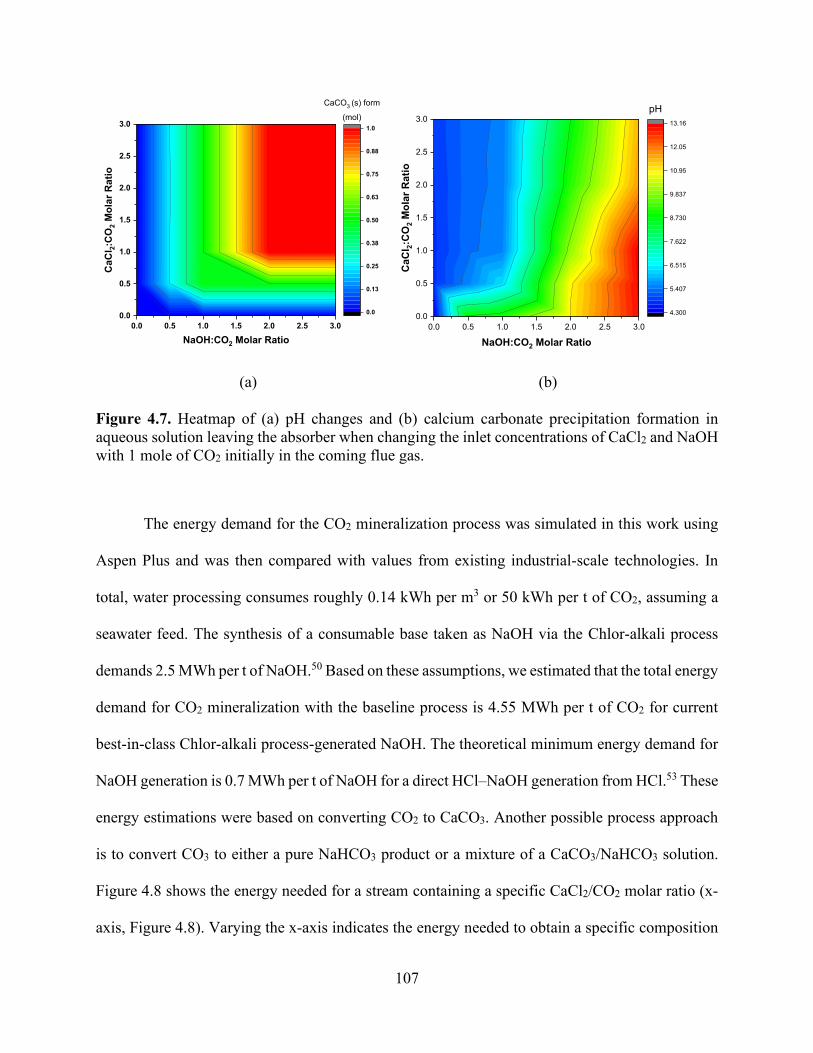
107
(a) (b)
Figure 4.7. Heatmap of (a) pH changes and (b) calcium carbonate precipitation formation in aqueous solution leaving the absorber when changing the inlet concentrations of CaCl2 and NaOH with 1 mole of CO2 initially in the coming flue gas.
The energy demand for the CO2 mineralization process was simulated in this work using
Aspen Plus and was then compared with values from existing industrial-scale technologies. In
total, water processing consumes roughly 0.14 kWh per m3 or 50 kWh per t of CO2, assuming a
seawater feed. The synthesis of a consumable base taken as NaOH via the Chlor-alkali process
demands 2.5 MWh per t of NaOH.50 Based on these assumptions, we estimated that the total energy
demand for CO2 mineralization with the baseline process is 4.55 MWh per t of CO2 for current
best-in-class Chlor-alkali process-generated NaOH. The theoretical minimum energy demand for
NaOH generation is 0.7 MWh per t of NaOH for a direct HCl–NaOH generation from HCl.53 These
energy estimations were based on converting CO2 to CaCO3. Another possible process approach
is to convert CO3 to either a pure NaHCO3 product or a mixture of a CaCO3/NaHCO3 solution.
Figure 4.8 shows the energy needed for a stream containing a specific CaCl2/CO2 molar ratio (x-
axis, Figure 4.8). Varying the x-axis indicates the energy needed to obtain a specific composition
0.0 0.5 1.0 1.5 2.0 2.5 3.00.0
0.5
1.0
1.5
2.0
2.5
3.0
CaC
l 2:C
O2 M
olar
Rat
io
NaOH:CO2 Molar Ratio
0.0
0.13
0.25
0.38
0.50
0.63
0.75
0.88
1.0
CaCO3 (s) form
(mol)
0.0 0.5 1.0 1.5 2.0 2.5 3.00.0
0.5
1.0
1.5
2.0
2.5
3.0
CaC
l 2:C
O2 M
olar
Rat
io
NaOH:CO2 Molar Ratio
4.300
5.407
6.515
7.622
8.730
9.837
10.95
12.05
13.16
pH
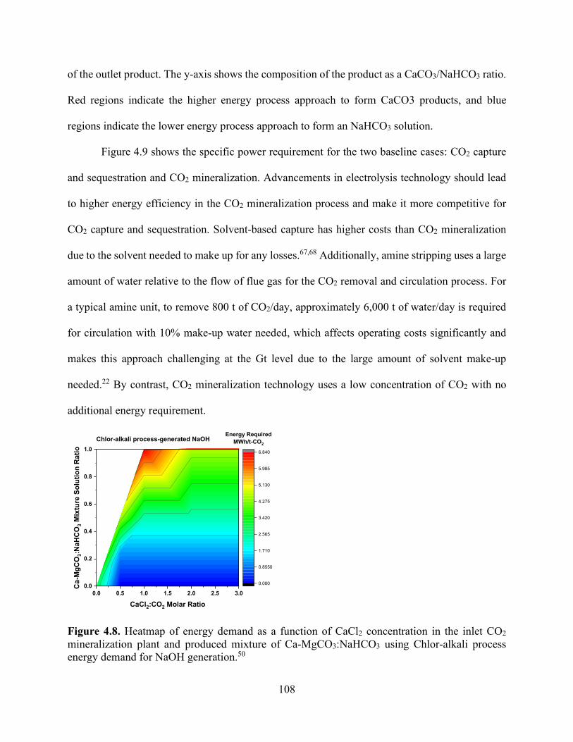
108
of the outlet product. The y-axis shows the composition of the product as a CaCO3/NaHCO3 ratio.
Red regions indicate the higher energy process approach to form CaCO3 products, and blue
regions indicate the lower energy process approach to form an NaHCO3 solution.
Figure 4.9 shows the specific power requirement for the two baseline cases: CO2 capture
and sequestration and CO2 mineralization. Advancements in electrolysis technology should lead
to higher energy efficiency in the CO2 mineralization process and make it more competitive for
CO2 capture and sequestration. Solvent-based capture has higher costs than CO2 mineralization
due to the solvent needed to make up for any losses.67,68 Additionally, amine stripping uses a large
amount of water relative to the flow of flue gas for the CO2 removal and circulation process. For
a typical amine unit, to remove 800 t of CO2/day, approximately 6,000 t of water/day is required
for circulation with 10% make-up water needed, which affects operating costs significantly and
makes this approach challenging at the Gt level due to the large amount of solvent make-up
needed.22 By contrast, CO2 mineralization technology uses a low concentration of CO2 with no
additional energy requirement.
Figure 4.8. Heatmap of energy demand as a function of CaCl2 concentration in the inlet CO2 mineralization plant and produced mixture of Ca-MgCO3:NaHCO3 using Chlor-alkali process energy demand for NaOH generation.50
0.0 0.5 1.0 1.5 2.0 2.5 3.00.0
0.2
0.4
0.6
0.8
1.0
Ca-
MgC
O3:N
aHC
O3 M
ixtu
re S
olut
ion
Rat
io
CaCl2:CO2 Molar Ratio
0.000
0.8550
1.710
2.565
3.420
4.275
5.130
5.985
6.840
Energy RequiredMWh/t-CO2
Chlor-alkali process-generated NaOH

109
Figure 4.9. Energy requirements for CO2 sequestration by (a) capture and injection in geologic formations (red and grey) and (b) baseline concept for carbon dioxide mineralization and disposal. Through NaOH generation by the Chlor-alkali process,50 this route entails two possible subroutes for CO2 converted products, NaHCO3 and CaCO3. The theoretical energy requirement for NaOH generation from NaCl has been shown to indicate the minimum energy needed.53
4.4.2 Advanced Cases
4.4.2.1 Reducing Power Consumption Below Baseline
Several process configurations were tested to reduce the power requirement for the CO2
mineralization process. The key feature of the advanced concept is to enhance the efficiency,
energy utilization, and possibility for process integration within existing and future desalination
plants, simultaneously addressing the issues of CO2-driven climate change and water supply.
A seawater reverse osmosis (SWRO) plant has been the dominant desalination technology
used to remove Mg2+/Ca2+-rich aqueous solutions from seawater in the industry due to the low
process cost.54 The energy cost of desalinating seawater can be estimated as 3.5 kWh/m3,
considering that the best current seawater RO process requires 2–2.5 kWh/m3 and additional

110
energy54; >1.0 kWh is consumed mainly by the intake and pretreatment of the desalination plant.40
Of these stages, the pretreatment of fresh seawater before it is fed into RO accounts for most of
the energy used. Seawater pretreatment consumes 0.3–1.0 kWh/m3, and as the salinity of water
increases, so does the required energy for pretreatment. For example, the energy required for
brackish water is 0.8–1.7 kWh/m3.54 Recent analysis has shown that there is a small marginal
potential for further energy saving in any desalination process.55,56 Nevertheless, the total energy
consumption of sea water reverse osmosis plants is around three to four times higher than the
minimum theoretical energy due to the involvement of pretreatment steps. Eliminating or reducing
the pretreatment stage would reduce the energy consumption of SWRO plants and reduce the
chemicals used that pose environmental hazards to creatures when discharged into the aquatic
environment.57,58 Aqueous sources such as seawater, subsurface brine, and industrial effluents are
also Mg2+/Ca2+-rich aqueous solutions and potentially applied for CO2 mineralization.34,35 Figure
4.9 compares the energy required for seawater and brackish water. Figure 4.10 illustrates that there
is an area to integrate the pretreatment step of RO desalination plants with CO2 mineralization,
leading to lower energy requirements. Our proposed alternative is to use the CO2 mineralization
unit in the pretreatment step of RO desalination plants to enhance the efficiency and energy
utilization of the CO2 capture and pretreatment process. Integrating the CO2 mineralization unit in
the pretreatment stage improves the energy efficiency of the SWRO plant because
thermodynamics sets the boundary of the desalination step energy requirement.56 Brackish water
is also a Mg2+/Ca2+-rich aqueous solution that can be integrated with CO2 mineralization to reduce
high disposal costs and limited disposal options.59–61 Previous experiments have shown that
seawater is a viable option to precipitate 90% of Ca and Mg ions in seawater, equivalent to 0.06

111
mol of CO2 that can be captured per liter of the natural seawater process. Additionally, two to three
times more CO2 fixation can potentially be achieved with more concentrated water.43
Figure 4.10. Specific energy required to treat different sources of wastewater (seawater and brackish water) broken down into components (red for pretreatment process prior to RO and green for the RO process energy requirements).40,54
In this section, we discuss changes in concentrated seawater composition (Ca, Mg; Table
4.2) with pH and CO2 flow rate and precipitation of carbonates. We evaluated a carbon capture
plant treating 45 kg/h of flue gas containing 15% (v/v) of CO2 from a supercritical pulverized coal
power plant. The coal-fired flue gas composition was 15% CO2, 4.0% H2O, 4.0% O2, and 77% N2
at 25 °C and 0.1 MPa. The plant was assumed to run 335 days per year at 100% capacity, with
90% capture efficiency of the emitted carbon from the power plant. A solution containing Ca2+
and Mg2+, which originate in sources such as waste brine produced by salt and potassium carbonate
industries (Table 4.2),62,63 was used as a continuous flow source (fixed at 1 m3/h) for a Ca2+/Mg2+-
seawater brackish water0
1
2
3
4
5
6
7
8En
ergy
Req
uire
d (k
Wh/
m3 )
desalination
pretreatment process RO process
integration potential

112
rich aqueous solution for the integration approach. The constraints of this study were to achieve
>90% CO2 and >90% Ca-Mg2+ on outlet flue gas and concentrated seawater streams, and thus, the
CO2 flow rate was adjusted to the value that gave the highest carbonation potential based on
concentrated seawater concentration. CO2 mineralization by this method is analogous in several
respects to water treatment. First, adequate mixing and CO2 equilibration can be enabled using
aeration tanks similar to those used in the activated sludge process in wastewater treatment plants.
Second, NaOH can be blended into the CO2-rich water, as in the processes of coagulation and
flocculation for water treatment, resulting in the precipitation of CaCO3 and MgCO3. The
precipitates are then separated from the solution by sedimentation, and the discharge solids can
either be further dewatered using techniques that are currently employed in water treatment, such
as rotary drum filters, or expelled into the ocean in a manner similar to brine disposal in
desalination plants.
The flue gas flow rate was chosen to be 45 kg/h to ensure that minimum carbon was
available to precipitate products. The pH of the concentrated seawater was adjusted by adding
sodium hydroxide medium while maintaining a constant flue gas flow (45 kg/h). After the addition
of 7 kg/h of NaOH, the concentration of Ca and Mg ions was reduced to less than 10% in the
treated brine solution (Figure 4.11). Beyond the addition of 7 kg/h, no more precipitates were
expected from the solution because nearly all the Mg and Ca had been already removed.

113
Table 4.2. Concentrated seawater compounds.62,63
Compound Concentration (g/L) Compound Concentration (g/L) NaCl 46.88 KBr 0.196
MgCl2 10.16 H3BO3 0.054 CaCl2 2.25 SrCl2 0.048
Na2SO4 7.99 NaF 0.006 KCl 1.33 NaHCO3 0.392
Figure 4.11. Effect of adding NaOH (bottom x-axis) to a concentrated brine composition (Ca, Mg) to adjust pH (left y-axis) that is in contact with flue gas at 45 kg/h to calculate carbonate precipitation. Effluent speciation (right y-axis) shows the reduction in Mg2+ (■ grey) and Ca2+ (■ black) for the solution as they form carbonates. Top x-axis shows the energy used and correlated to NaOH is added to solution.
Oil-field brine is another wastewater source that was used in this study. Oil-field brine
composition was based on a water treatment plant that collects oil-field brine and underground
deep natural gas brine from various wells in Pennsylvania, USA.31 A similar approach to
0 1 2 3 4 5 6 7 8 9 10
0 3 5 8 10 13 15 18 20 23 25
6
7
8
9
10
11
12
13
14
Treatment Energy (kWh/m3)
pH
NaOH mass flow rate (kg/hr)
pH
0
1
2
3
4
5
6
7
8
remove > 90% Ca-Mg2+ and CO2
corresponds to right y-xaxis
CO2 (g) Mg2+
Ca2+
Trea
ted
Brin
e C
once
ntra
tion
(g/L
)
CO2 concentration in the outlet flue gas (kg/hr)
based on Chloralkali process
Energy needed for the target to

114
concentrated seawater was developed for this case; the results of this study are reported in the
following section 3.2.2.
Table 4.3 Oil-field brine compounds.31
Compound Concentration (g/L) Compound Concentration (g/L) NaCl 62.780 FeCl3 0.43
MgCl2 1.837 SrCl2 10.04 CaCl2 33.45 BaCl2 0.89 KCl 2.350
4.4.2.2 Integration Approach
The potential of using integration to fix CO2 was evaluated according to the following
equation.43,62 The calculation was based on Mg, Ca in an aqueous solution of concentrated brine
(Table 4.2) in addition to any bicarbonate formation in the solution. CO2 fixation comes from Mg2+
and Ca2+ in a concentrated solution.
𝐶𝐶𝑜𝑜𝑎𝑎𝑥𝑥𝑎𝑎𝑎𝑎𝑎𝑎𝑜𝑜𝑎𝑎 = 𝐶𝐶𝐶𝐶𝑎𝑎𝐶𝐶𝑂𝑂3 + 𝐶𝐶𝑀𝑀𝑒𝑒𝐶𝐶𝑂𝑂3 + 𝐶𝐶𝑁𝑁𝑎𝑎𝐻𝐻𝐶𝐶𝑂𝑂3 (19)
where 𝐶𝐶𝑜𝑜𝑎𝑎𝑥𝑥𝑎𝑎𝑎𝑎𝑎𝑎𝑜𝑜𝑎𝑎 is the total CO2 fixed in the process by carbonate precipitation and
bicarbonate formation.
The value of 𝐶𝐶𝑜𝑜𝑎𝑎𝑥𝑥𝑎𝑎𝑎𝑎𝑎𝑎𝑜𝑜𝑎𝑎 has been calculated as 0.18 mol of CO2/m3 of concentrated seawater.
This is the carbon fixation where 1 m3 of concentrated seawater can capture roughly 8 kg of CO2
under standard conditions. Oil-field brine has higher Ca and Mg concentrations (Table 4.3), and
thus more, CO2 capture potential per m3 of solution (23 kg of CO2/m3 of oil-field brine solution).
Figures 4.12 and 4.13 show the effect of NaOH mass flow rate on the carbonate products
proportions of MgCO3, MgCO3·3H2O, CaCO3, and NaHCO3 for two wastewater sources:
concentrated seawater and oil-field brine solutions, respectively. The simultaneous addition of
NaOH results in the precipitation of calcite and nesquehonite, up to roughly 89 mmol
nesquehonites and approximately 23 mmol calcite/m3 of treated concentrated seawater solution

115
and approximately 296 mmol calcite and roughly 16 mmol nesquehonites/m3 of treated oil-field
brine solution. The shaded regions represent the percentage of nesquehonite, calcite, and
bicarbonate converted from CO2 to carbonates, and the blue curve represents the decrease in the
CO2-treated flue gas flow rate with the addition of NaOH.
Figure 4.12. Effect of NaOH mass flow rate (bottom x-axis) to the carbonate products proportions of MgCO3 (red region), MgCO3·3H2O (orange region), CaCO3 (blue region), and NaHCO3 (green region). The change in CO2 flue gas concentration for the stream leaving the absorber is shown in the blue line; at 7 kg/h NaOH, CO2 is completely removed.
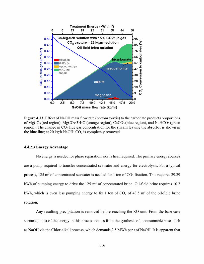
116
Figure 4.13. Effect of NaOH mass flow rate (bottom x-axis) to the carbonate products proportions of MgCO3 (red region), MgCO3·3H2O (orange region), CaCO3 (blue region), and NaHCO3 (green region). The change in CO2 flue gas concentration for the stream leaving the absorber is shown in the blue line; at 20 kg/h NaOH, CO2 is completely removed.
4.4.2.3 Energy Advantage
No energy is needed for phase separation, nor is heat required. The primary energy sources
are a pump required to transfer concentrated seawater and energy for electrolysis. For a typical
process, 125 m3 of concentrated seawater is needed for 1 ton of CO2 fixation. This requires 29.29
kWh of pumping energy to drive the 125 m3 of concentrated brine. Oil-field brine requires 10.2
kWh, which is even less pumping energy to fix 1 ton of CO2 of 43.5 m3 of the oil-field brine
solution.
Any resulting precipitation is removed before reaching the RO unit. From the base case
scenario, most of the energy in this process comes from the synthesis of a consumable base, such
as NaOH via the Chlor-alkali process, which demands 2.5 MWh per t of NaOH. It is apparent that
117
the CO2 mineralization approach with integration improves efficiency and reduces costs.
Efficiency is increased by 10% relative to CO2 mineralization only.
An efficient process integration to reduce extra pretreatment requirements for Ca2+/Mg2+-
rich aqueous solutions while capturing CO2 at the same time to form carbonate solution was
investigated. This resulted in a reduction in total power consumption for the process if each were
treated independently. In an integrated mineralization pretreatment–desalination process, the total
energy can be estimated as 18 kWh/m3 of concentrated seawater and 7 kg of CO2 stored, which is
equivalent to a net energy reduction of the overall process by 10% considering that standalone
concentrated seawater pretreatment requires 1.7 kWh/m3.40,54 Oil-field brine uses more energy to
remove 90% of Ca and Mg from the solution (50 kWh/m3); however, it has higher CO2 capture
potential per m3 of wastewater solution (Figure 4.13). Operating expense has a direct relationship
with NaOH synthesis energy; thus, further improvement in electrolysis technology can enable this
integration route to be more competitive as a replacement for the current desalination pretreatment
process (Figure 4.14). Recycled wastewater may indeed emerge as one of the most important water
supplies in the future, particularly for water-scarce regions.

118
Figure 4.14. Specific energy requirement to treat different sources of wastewater broken down into components (red for pretreatment process prior to RO and green for the RO process energy requirements) compared with energy required to treat the same wastewater sources through CO2 mineralization approach. Dotted rectangle shape shows the integration potential to reduce energy required to treat water (kWh/m3) by combined CO2 mineralization and RO plants.
seawater brackish water brackish water brackish water0
2
4
6
8
10
12
14
16
18
20
long termEn
ergy
Req
uire
d (k
Wh/
m3 )
desalination
CO2 mineralization (remove Ca-Mg2+) pretreatment process RO process
CO2 mineralization
integration potential
competitive in
via ChloralkaliCO2 mineralization
minimum energy
Energy Efficiency

119
4.5 Conclusion
We can conclude from our assessment about an amine-unit CO2 capture plant that although
it has been widely used to capture CO2, the energy used for amine regeneration still represents a
significant challenge. In addition to regeneration energy used in the amine unit, in some cases, we
need to pressurize a 100% CO2 gaseous stream from atmospheric pressure to 140 bar to store it
underground, and the energy demand used for compression was estimated using a four-stage
compressor with inter-stage coolers, which require 0.22 MWh per t-CO2. Alternatively, CO2 can
be fixed by the production of insoluble carbonate salt through the carbonation process of a caustic
solution’s absorbing CO2, which is another option for CO2 capture. Distinct from the carbon
capture and sequestration, the mineralization approach does not necessitate overcoming the energy
of separating CO2 from a mixture of gases and can be utilized without energy rise over a wide
range of CO2 concentrations and temperatures.
In the framework of an integrated CO2 mineralization plant, Ca-Mg2+ can be mineralized
and integrated with the desalination plant. The intensification of the CO2 capture process with a
desalination plant was explored through the integration of CO2 mineralization with a pretreatment
plant. This study proposed a CO2 mineralization process that integrates low-concentration CO2 (15
vol %) obtained from coal-fired power plants with wastewater treatment and produces carbonate
materials. It was found that the CO2 configuration yielded a 10% decrease in the total energy of
separation required. The process shows that a concentrated solution containing Ca2+/Mg2+ solution
can be used to fix CO2 using the hydroxide produced by electrolysis.

120
4.6 References
1. Heuberger, C. F.; Staffell, I.; Shah, N.; Mac Dowell, N. Impact of Myopic Decision-Making
and Disruptive Events in Power Systems Planning. Nat. Energy 2018, 3 (8), 634–640.
https://doi.org/10.1038/s41560-018-0159-3.
2. Shepherd, J. G. Geoengineering the Climate: Science, Governance and Uncertainty; Royal
Society, 2009.
3. Pogge von Strandmann, P. A. E.; Burton, K. W.; Snæbjörnsdóttir, S. O.; Sigfússon, B.;
Aradóttir, E. S.; Gunnarsson, I.; Alfredsson, H. A.; Mesfin, K. G.; Oelkers, E. H.; Gislason, S.
R. Rapid CO2 Mineralisation into Calcite at the CarbFix Storage Site Quantified Using
Calcium Isotopes. Nat. Commun. 2019, 10 (1), 1983. https://doi.org/10.1038/s41467-019-
10003-8.
4. Seifritz, W. CO2 Disposal by Means of Silicates. Nature 1990, 345 (6275), 486.
5. Alexander, G.; Maroto-Valer, M. M.; Gafarova-Aksoy, P. Evaluation of Reaction Variables in
the Dissolution of Serpentine for Mineral Carbonation. Fuel 2007, 86 (1–2), 273–281.
6. Dlugogorski, B. Z.; Balucan, R. D. Dehydroxylation of Serpentine Minerals: Implications for
Mineral Carbonation. Renew. Sustain. Energy Rev. 2014, 31, 353–367.
7. Park, A.-H. A.; Fan, L.-S. CO2 Mineral Sequestration: Physically Activated Dissolution of
Serpentine and PH Swing Process. Chem. Eng. Sci. 2004, 59 (22–23), 5241–5247.
8. Kakizawa, M.; Yamasaki, A.; Yanagisawa, Y. A New CO2 Disposal Process via Artificial
Weathering of Calcium Silicate Accelerated by Acetic Acid. Energy 2001, 26 (4), 341–354.
9. Huijgen, W. J. J.; Witkamp, G.-J.; Comans, R. N. J. Mechanisms of Aqueous Wollastonite
Carbonation as a Possible CO2 Sequestration Process. Chem. Eng. Sci. 2006, 61 (13), 4242–
4251.

121
10. Daval, D.; Martinez, I.; Corvisier, J.; Findling, N.; Goffé, B.; Guyot, F. Carbonation of Ca-
Bearing Silicates, the Case of Wollastonite: Experimental Investigations and Kinetic
Modeling. Chem. Geol. 2009, 265 (1–2), 63–78.
11. Huijgen, W. J. J.; Comans, R. N. J.; Witkamp, G.-J. Cost Evaluation of CO2 Sequestration by
Aqueous Mineral Carbonation. Energy Convers. Manag. 2007, 48 (7), 1923–1935.
https://doi.org/https://doi.org/10.1016/j.enconman.2007.01.035.
12. Ghoorah, M.; Dlugogorski, B. Z.; Balucan, R. D.; Kennedy, E. M. Selection of Acid for Weak
Acid Processing of Wollastonite for Mineralisation of CO2. Fuel 2014, 122, 277–286.
13. Munz, I. A.; Kihle, J.; Brandvoll, Ø.; Machenbach, I.; Carey, J. W.; Haug, T. A.; Johansen, H.;
Eldrup, N. A Continuous Process for Manufacture of Magnesite and Silica from Olivine, CO2
and H2O. Energy Procedia 2009, 1 (1), 4891–4898.
14. Zevenhoven, R.; Fagerlund, J.; Songok, J. K. CO2 Mineral Sequestration: Developments
toward Large-Scale Application. Greenh. Gases Sci. Technol. 2011, 1 (1), 48–57.
https://doi.org/10.1002/ghg3.7.
15. Fagerlund, J.; Teir, S.; Nduagu, E.; Zevenhoven, R. Carbonation of Magnesium Silicate
Mineral Using a Pressurised Gas/Solid Process. Energy Procedia 2009, 1 (1), 4907–4914.
16. Koukouzas, N.; Gemeni, V.; Ziock, H. J. Sequestration of CO2 in Magnesium Silicates, in
Western Macedonia, Greece. Int. J. Miner. Process. 2009, 93 (2), 179–186.
https://doi.org/10.1016/j.minpro.2009.07.013.
17. Oelkers, E. H.; Gislason, S. R.; Matter, J. Mineral Carbonation of CO2. Elements 2008, 4 (5),
333–337.
18. Oelkers, E. H. An Experimental Study of Forsterite Dissolution Rates as a Function of
Temperature and Aqueous Mg and Si Concentrations. Chem. Geol. 2001, 175 (3–4), 485–494.

122
19. Krevor, S. C.; Lackner, K. S. Enhancing Process Kinetics for Mineral Carbon Sequestration.
Energy Procedia 2009, 1 (1), 4867–4871.
20. Mei, Z. H.; Mei, S. Y. Novel Economical Chemical Engineering Reactions for Mineralization
of CO2 to Combat Global Warming. In Advanced Materials Research; Trans Tech Publ, 2012;
Vol. 524, pp 3302–3307.
21. Sanna, A.; Uibu, M.; Caramanna, G.; Kuusik, R.; Maroto-Valer, M. M. A Review of Mineral
Carbonation Technologies to Sequester CO2. Chem. Soc. Rev. 2014, 43 (23), 8049–8080.
https://doi.org/10.1039/c4cs00035h.
22. Rackley, S. A. 2 - Overview of Carbon Capture and Storage; Rackley, S. A. B. T.-C. C. and S.
(Second E., Ed.; Butterworth-Heinemann: Boston, 2017; pp 23–36.
https://doi.org/https://doi.org/10.1016/B978-0-12-812041-5.00002-7.
23. Lackner, K. S.; Wendt, C. H.; Butt, D. P.; Joyce Jr, E. L.; Sharp, D. H. Carbon Dioxide
Disposal in Carbonate Minerals. Energy 1995, 20 (11), 1153–1170.
24. Moriyoshi, Y.; Fukawa, J.; Ishibe, E.; Ikegami, T. Fixation of Carbon Dioxide with
Wollastonite and Its Reaction Products. Trans Mater Res Soc Jpn 1999, 24 (4), 611–614.
25. Landrot, G.; Ajo-Franklin, J. B.; Yang, L.; Cabrini, S.; Steefel, C. I. Measurement of
Accessible Reactive Surface Area in a Sandstone, with Application to CO2 Mineralization.
Chem. Geol. 2012, 318, 113–125.
26. Rendek, E.; Ducom, G.; Germain, P. Carbon Dioxide Sequestration in Municipal Solid Waste
Incinerator (MSWI) Bottom Ash. J. Hazard. Mater. 2006, 128 (1), 73–79.
27. Kodama, S.; Nishimoto, T.; Yamamoto, N.; Yogo, K.; Yamada, K. Development of a New
PH-Swing CO2 Mineralization Process with a Recyclable Reaction Solution. Energy 2008, 33
(5), 776–784. https://doi.org/https://doi.org/10.1016/j.energy.2008.01.005.
123
28. Nduagu, E.; Björklöf, T.; Fagerlund, J.; Wärnå, J.; Geerlings, H.; Zevenhoven, R. Production
of Magnesium Hydroxide from Magnesium Silicate for the Purpose of CO2 Mineralisation–
Part 1: Application to Finnish Serpentinite. Miner. Eng. 2012, 30, 75–86.
29. Xie, H.-P.; Xie, L.-Z.; Wang, Y.-F.; Zhu, J.-H.; Liang, B.; Ju, Y. CCU: A More Feasible and
Economic Strategy than CCS for Reducing CO2 Emissions. J. Sichuan Univ. Eng. Sci. Ed.
2012, 44 (4), 1–5.
30. Xie, H.; Wang, Y.; Ju, Y.; Liang, B.; Zhu, J.; Zhang, R.; Xie, L.; Liu, T.; Zhou, X.; Zeng, H.
Simultaneous Mineralization of CO2 and Recovery of Soluble Potassium Using Earth-
Abundant Potassium Feldspar. Chinese Sci. Bull. 2013, 58 (1), 128–132.
31. Sanna, A.; Dri, M.; Hall, M. R.; Maroto-Valer, M. Waste Materials for Carbon Capture and
Storage by Mineralisation (CCSM) – A UK Perspective. Appl. Energy 2012, 99, 545–554.
https://doi.org/https://doi.org/10.1016/j.apenergy.2012.06.049.
32. Pan E.E. and Chiang, Pen-Chi, S.-Y. and C. CO2 Capture by Accelerated Carbonation of
Alkaline Wastes: A Review on Its Principles and Applications. Aerosol Air Qual. Res. 2012,
12 (5), 770–791. https://doi.org/10.4209/aaqr.2012.06.0149.
33. Pan, S.-Y.; Chiang, P.-C.; Chen, Y.-H.; Chen, C.-D.; Lin, H.-Y.; Chang, E.-E. Systematic
Approach to Determination of Maximum Achievable Capture Capacity via Leaching and
Carbonation Processes for Alkaline Steelmaking Wastes in a Rotating Packed Bed. Environ.
Sci. Technol. 2013, 47 (23), 13677–13685. https://doi.org/10.1021/es403323x.
34. Rau, G. H. CO2 Mitigation via Capture and Chemical Conversion in Seawater. Environ. Sci.
Technol. 2010, 45 (3), 1088–1092.
35. Sanna, A.; Uibu, M.; Caramanna, G.; Kuusik, R.; Maroto-Valer, M. M. A Review of Mineral
Carbonation Technologies to Sequester CO2. Chem. Soc. Rev. 2014, 43 (23), 8049–8080.

124
https://doi.org/10.1039/C4CS00035H.
36. Zevenhoven, R.; Eloneva, S.; Teir, S. Chemical Fixation of CO2 in Carbonates: Routes to
Valuable Products and Long-Term Storage. Catal. Today 2006, 115 (1), 73–79.
https://doi.org/https://doi.org/10.1016/j.cattod.2006.02.020.
37. Druckenmiller, M. L.; Maroto-Valer, M. M. Carbon Sequestration Using Brine of Adjusted
PH to Form Mineral Carbonates. Fuel Process. Technol. 2005, 86 (14), 1599–1614.
https://doi.org/https://doi.org/10.1016/j.fuproc.2005.01.007.
38. Liu, Q.; Mercedes Maroto-Valer, M. Investigation of the Effect of Brine Composition and PH
Buffer on CO2 -Brine Sequestration. Energy Procedia 2011, 4, 4503–4507.
https://doi.org/https://doi.org/10.1016/j.egypro.2011.02.406.
39. Roach, R. W.; Carr, R. S.; Howard, C. L.; Cain, B. W.; Carrý, R.; Station, C. Assessment of
Produced Water Impacts in Galveston Bay System. US Fish Wildl. Report, Clear Lake Ecol.
Serv. Off. Houston, TX 1992.
40. Puder, M. G.; Veil, J. A. Options, Methods, and Costs for Offsite Commercial Disposal of
Exploration and Production Wastes. SPE Proj. Facil. Constr. 2007, 2 (04), 1–5.
41. Soong, Y.; Fauth, D. L.; Howard, B. H.; Jones, J. R.; Harrison, D. K.; Goodman, A. L.; Gray,
M. L.; Frommell, E. A. CO2 Sequestration with Brine Solution and Fly Ashes. Energy
Convers. Manag. 2006, 47 (13), 1676–1685.
https://doi.org/https://doi.org/10.1016/j.enconman.2005.10.021.
42. Kharaka, Y. K.; Leong, L. Y. C.; Doran, G.; Breit, G. N. Can Produced Water Be Reclaimed?
Experience with Placerita Oil Field, California. In Proceedings of the 5th international
petroleum environmental conference, Albuquerque, NM; 1998.
43. Wang, W.; Hu, M.; Zheng, Y.; Wang, P.; Ma, C. CO2 Fixation in Ca2+-/Mg2+-Rich Aqueous

125
Solutions through Enhanced Carbonate Precipitation. Ind. Eng. Chem. Res. 2011, 50 (13),
8333–8339. https://doi.org/10.1021/ie1025419.
44. Chen, C.-C.; Song, Y. Generalized Electrolyte-NRTL Model for Mixed-Solvent Electrolyte
Systems. AIChE J. 2004, 50 (8), 1928–1941. https://doi.org/10.1002/aic.10151.
45. Bui, M.; Tait, P.; Lucquiaud, M.; Mac Dowell, N. Dynamic Operation and Modelling of
Amine-Based CO2 Capture at Pilot Scale. Int. J. Greenh. Gas Control 2018, 79, 134–153.
46. Mota-Martinez, M. T.; Brandl, P.; Hallett, J. P.; Mac Dowell, N. Challenges and Opportunities
for the Utilisation of Ionic Liquids as Solvents for CO2 Capture. Mol. Syst. Des. Eng. 2018, 3
(3), 560–571.
47. Cui, Q.; Lu, H.; Li, C.; Singh, S.; Ba, L.; Zhao, X.; Ku, A. Y. China Baseline Coal-Fired Power
Plant with Post-Combustion CO2 Capture: 1. Definitions and Performance. Int. J. Greenh. Gas
Control 2018, 78, 37–47.
48. Rao, A. B.; Rubin, E. S. A Technical, Economic, and Environmental Assessment of Amine-
Based CO2 Capture Technology for Power Plant Greenhouse Gas Control. Environ. Sci.
Technol. 2002, 36 (20), 4467–4475. https://doi.org/10.1021/es0158861.
49. MacDowell, N.; Florin, N.; Buchard, A.; Hallett, J.; Galindo, A.; Jackson, G.; Adjiman, C. S.;
Williams, C. K.; Shah, N.; Fennell, P. An Overview of CO2 Capture Technologies. Energy
Environ. Sci. 2010, 3 (11), 1645–1669.
50. Chlistunoff, J. Advanced Chlor-Alkali Technology. 2004.
51. Cabral, R. P.; Heldebrant, D. J.; Mac Dowell, N. A Techno-Economic Analysis of a Novel
Solvent-Based Oxycombustion CO2 Capture Process. Ind. Eng. Chem. Res. 2019, 58 (16),
6604–6612. https://doi.org/10.1021/acs.iecr.9b00305.
52. Singh, D.; Croiset, E.; Douglas, P. L.; Douglas, M. A. Techno-Economic Study of CO2

126
Capture from an Existing Coal-Fired Power Plant: MEA Scrubbing vs. O2/CO2 Recycle
Combustion. Energy Convers. Manag. 2003, 44 (19), 3073–3091.
https://doi.org/10.1016/S0196-8904(03)00040-2.
53. Thiel, G. P.; Kumar, A.; Gómez-González, A.; Lienhard, J. H. Utilization of Desalination Brine
for Sodium Hydroxide Production: Technologies, Engineering Principles, Recovery Limits,
and Future Directions. ACS Sustain. Chem. Eng. 2017, 5 (12), 11147–11162.
https://doi.org/10.1021/acssuschemeng.7b02276.
54. Bartels, C. R.; Andes, K. Consideration of Energy Savings in SWRO. Desalin. Water Treat.
2013, 51 (4–6), 717–725.
55. Song, L.; Hu, J. Y.; Ong, S. L.; Ng, W. J.; Elimelech, M.; Wilf, M. Emergence of
Thermodynamic Restriction and Its Implications for Full-Scale Reverse Osmosis Processes.
Desalination 2003, 155 (3), 213–228.
56. Elimelech, M.; Phillip, W. A. The Future of Seawater Desalination: Energy, Technology, and
the Environment. Science (80-. ). 2011, 333 (6043), 712–717.
57. Council, N. R. Committee on Advancing Desalination Technology. Desalin. a Natl. Perspect.
2008.
58. Lattemann, S.; Höpner, T. Environmental Impact and Impact Assessment of Seawater
Desalination. Desalination 2008, 220 (1), 1–15.
https://doi.org/https://doi.org/10.1016/j.desal.2007.03.009.
59. Benko, K. L.; Drewes, J. E. Produced Water in the Western United States: Geographical
Distribution, Occurrence, and Composition. Environ. Eng. Sci. 2008, 25 (2), 239–246.
60. Consulting, A. L. L. Handbook on Coal Bed Methane Produced Water: Management and
Beneficial Use Alternatives. Prep. Groundw. Prot. Res. Found. US Dep. Energy, Natl. Pet.

127
Technol. Ofce, Bur. L. Manag. July 2003.
61. Veil, J. A.; Puder, M. G.; Elcock, D.; Redweik Jr, R. J. A White Paper Describing Produced
Water from Production of Crude Oil, Natural Gas, and Coal Bed Methane.; Argonne National
Lab., IL (US), 2004.
62. Wang, W.; Liu, X.; Wang, P.; Zheng, Y.; Wang, M. Enhancement of CO2 Mineralization in
Ca2+-/Mg2+-Rich Aqueous Solutions Using Insoluble Amine. Ind. Eng. Chem. Res. 2013, 52
(23), 8028–8033. https://doi.org/10.1021/ie400284v.
63. Millero, F. J. Chemical Oceanography; CRC press, 2016.

128
Chapter 5: Application of Ion-Exchange Processes for CO2 Mineralization
5.1 Abstract
We propose a new process to produce an alkali solution that is subsequently utilized for
the mineralization of carbon dioxide using an ion-exchange approach. In this scheme, the
capacities for ion exchange of various zeolites and ion-exchange resins in CO2-saturated water
were studied through batch equilibrium and column ion-exchange experiments. The analysis of
solution-phase concentration and solid phases and the rate of exchange of Na+ for H+ were studied
across a range of temperatures, solution compositions, and solution conditions (i.e., static and
convectively mixed). For all the tested materials, weakly acidic ion exchangers exhibited superior
Na+/H+ exchange capacity in comparison to the highly acidic ion exchangers. Ion-exchange resins
that contains weakly acidic functional groups such as carboxylic acid exhibited higher affinity for
H+, increasing pH from 4 to 11.3 and surpassing the pH shift induced by the zeolitic materials. The
equilibrium ion exchange isotherms for Na+/Ca2+, Na+/Mg2+, and Na+/Fe2+ aqueous solutions were
also collected to assess the possibility of using ion exchange to increase the pH of carbonated water
in an industrial flue gas stream with the presence of ions other than H+ such as Ca2+, Mg2+, and
Fe2+.

129
5.2 Introduction
CO2 mineralization is attractive to sequester CO2 as it captures it as an insoluble carbonate mineral,
imitating the rock weathering natural process. CO2 mineralization is described in Eqs. (1)–(4).
Alkaline pH is essential for the change in speciation of CO2 to CO32−, as shown in Eqs. (2) and
(3), which reacts with calcium and magnesium ions for precipitation as shown in Eq. (4). This
approach involves the conversion of CO2 to carbonate minerals, offering an advantage in terms of
energy savings and storage capacity as solid carbonate minerals, which alleviates the risk of gas
leakage over an extended period of time.1 Precipitation of calcite in aqueous solutions is favored
by high Ca2+ and CO32− concentrations and pH. Precipitation of calcite involves a decrease in pH,
which eventually limits further precipitation according to the following equations:
CO2 (g) ⇌ 𝐶𝐶𝑂𝑂2 (𝑎𝑎𝑞𝑞) (1)
𝐶𝐶𝑂𝑂2 (𝑎𝑎𝑞𝑞) + 𝑂𝑂𝐻𝐻− (𝑎𝑎𝑞𝑞) → 𝐻𝐻𝐶𝐶𝑂𝑂3− (𝑎𝑎𝑞𝑞) (2)
𝐻𝐻𝐶𝐶𝑂𝑂3− (𝑎𝑎𝑞𝑞) + 𝑂𝑂𝐻𝐻− (𝑎𝑎𝑞𝑞) → 𝐻𝐻2𝑂𝑂 + 𝐶𝐶𝑂𝑂32− (𝑎𝑎𝑞𝑞) (3)
𝐶𝐶𝑎𝑎2+/ 𝑀𝑀𝑔𝑔2+ (𝑎𝑎𝑞𝑞) + 𝐶𝐶𝑂𝑂32− (𝑎𝑎𝑞𝑞) → 𝐶𝐶𝑎𝑎/𝑀𝑀𝑔𝑔 𝑐𝑐𝑎𝑎𝑟𝑟𝑏𝑏𝑚𝑚𝑛𝑛𝑎𝑎𝑡𝑡𝑐𝑐𝑐𝑐 (𝑐𝑐) + ℎ𝑐𝑐𝑎𝑎𝑡𝑡 (4)
The main challenge in this process is to maintain the alkalinity during carbonation. The use
of hydroxide (OH−) in alkaline aqueous solution to capture CO2 has received attention recently as
part of the viable carbon capture and sequestration (CCS) approach.2 The increase of alkalinity
makes a more thermodynamic environment to precipitate calcite. Mineral carbonation has been
demonstrated in Ca-rich solids that are rich in Ca2+ such as slags,3,4 other calcium silicates,5 and
waste concrete.6 Mineral carbonation has also been demonstrated in processes that utilize brines
as the Ca source.1 The potential simplicity and low-cost implementation of using an alkaline
solution for the CCS approach represent a substantial opportunity to mitigate CO2 emissions.2

130
Previous studies have relied on the costly and unsustainable consumption of alkalinity sources
such as natural minerals and solid waste.7–11 Kodama et al.12 used steelmaking slag and ammonium
chloride solution to convert CO2 to CaCO3. The major disadvantage of these methods is the
continuous need to add NaOH and secondary waste production. Ion-exchange processes can be
used as an alternative method to the addition of stoichiometric inorganic bases such as sodium
hydroxide to provide alkalinity for the consequential precipitation of CaCO3. In this process, we
used regenerable solids to increase the water pH through ion exchange and provide alkalinity. In
principle, ions exchange between an electrolyte solution source and the similar charged ions fixed
in an ion exchange material through a stoichiometric reversible ion-exchange reaction. Previous
research has shown that both the forward and reverse H+/Na+ exchanges can occur.13–15
Ion exchange technology is usually used water purification by eliminating the dissolved
ions through sorption by ion-exchange materials that have several physical forms.16,17 An ion
exchanger is a soluble material that has a functional group that traps and releases ions. The
occurrence of a mobile ion having a charge that is opposite to the fixed ions neutralizes the ion's
electrical charges.16 Due to the specific structural feature of zeolites, all zeolites can serve as ion
exchangers. However, only a limited number of these are used for practical applications. Ion-
exchange efficiency is directly associated with content of aluminum in the zeolite. High-alumina
zeolites are favored for ion-exchange applications.18 The most commonly used synthetic zeolites
in ion-exchange applications are Linde Type A (LTA) 19 and Linde Type X (FAU)20 due to their
high alumina content and easily accessible pore systems.21 Ion exchange and selectivity in zeolites
are mainly influenced by the exchangeable cations properties, the concentration of the solution,
presence of other cations, and characteristics of zeolite such as channels and Si/Al ratio.22 There
are no separate ionogenic groups of zeolites; their lattice consists of SiO4 and AlO4 tetrahedra,

131
which have an oxygen atom in shared. Since aluminum is trivalent, the lattice has a negative
electric charge which is balanced by alkali and alkaline earth cations that do not inhabit fixed sites
but are able to move in the framework channels. Zeolite has been used because of its large number
of active sites and large surface area. Synthetic resins are typically cast as porous beads with so-
called matrix consisting of hydrocarbon chains with considerable external and porous surfaces
where ions can bind. They contain ionizable groups placed along their chains. These radicals are
fixed in the framework and are ionogenic groups of the resins. They can be classified, based on
the functional group, into strongly and weakly acidic materials. Ion-exchange resins that contain
phosphorate acid (–PO3) groups and sulfonate (–SO3) groups are strongly acidic resins. By
contrast, materials containing phenolic (–OH) groups are weakly acidic and resins containing
carboxyl groups (–COO) are in between strong and weak acidic exchangers.23 Each of these major
classes imitates the ionization extent, with the pH of the solution imparting different physical and
chemical properties.24
In this work, we investigated a mineralization route that capture flue gas CO2 using ion
exchange technique through aqueous waste streams to convert CO2 into carbonate precipitation.
Maintaining alkalinity during carbonation is a prime challenge for CO2 mineralization. Therefore,
an ion-exchange cycle is developed to provide alkalinity. This section discusses the demonstration
of these processes by identifying suitable materials and process parameters. The primary objective
was to increase the pH of aqueous solution through the exchange of Na+ within the ion-exchange
material with H+. Therefore, to better understand these aspects, monovalent exchange was studied
across a range of H+ concentrations at different temperatures (i.e., 5 °C, 25 °C, and 40 °C) and
different solution conditions (i.e., static and convectively mixed).

132
5.3 Experimental Procedure
5.3.1 Materials
Sodium hydroxide (96%, PRS grade) and nitric acid (65% w/w, Pa grade) were supplied
by Sigma-Aldrich. Demineralized water was used with a conductivity value of less than 5 μScm−1.
A variety of ion-exchange resins and zeolites were assessed for their ability to increase the pH of
carbonated water. The resins used in this study were from different functional groups and in the
Na+ form. The strongly acidic cationic exchange resins used were with sulfonic groups fixed on
the polystyrene divinylbenzene matrix such as synthetic Amberlite IR-120 in sodium form (16–45
mesh size), synthetic Lewatit Mono Plus SP 112 in sodium form, synthetic Amberlite 200 C in
sodium form, and synthetic Diaion SK11, all of which were obtained from Sigma-Aldrich. Weakly
acidic resins such as Lewatit TP-260 with di-Na+ (aminomethyl) phosphonic acid groups and
Lewatit TP-207 in the sodium form with iminodiacetic acid groups. The physical properties and
chemical properties of the resins are summarized in Table 1. Commercially available zeolites 13X
and 4A were obtained in sodium form from Thermo Fisher Scientific. Zeolites with a porous
structure that can accommodate a wide variation of cations, such as Na+, K+, Ca2+, and Mg2+, and
can be exchanged readily with other cations in a solution were used. Their lattice consists of SiO4
and AlO4 tetrahedra, which have an oxygen atom in common. The lattice has a negative electric
charge that is balanced by cations that do not occupy fixed positions but are free to move within
the channels of the framework. These cations act as counterions to the fixed anion and can be
substituted by other cations.24 Therefore, the negative charge of zeolites is not localized but is
uniformly distributed in the framework. Unlike the charge in resin, the framework charge does not
depend on the external conditions.

133
Table 5.1. Characteristics of the chelating resins.
TP 207 IRA 120 SP 112 Structure Macroporous weak
acid Gel of strong acid Cation exchange resin
Macroporous Cross-linked polystyrene
Matrix Cross-linked polystyrene
Styrene–divinylbenzene copolymer
Cross-linked polystyrene
Functional group Iminodiacetic acid Sulfonic acid Sulfonic acid Average particle size 0.61 mm 0.5 mm 0.65 mm Bulk density 0.72 g/cm3 1.24 g/L Density 1.1 g/cm3 Total exchange capacity
2.2 meq/g 1.9 meq/m 1.7 eq/L
pH range pH 0–14 0–14
200C IRA 120 TP 260 Structure Macroporous cross-
linked polystyrene Styrene Macroporous weak acid
Matrix Cross-linked polystyrene
Styrene–divinylbenzene copolymer
Cross-linked polystyrene
Functional group Iminodiacetic acid Sulphonic Aminomethylphosphonic acid
Average particle size
0.60–0.850 mm 0.3–1.2 mm 0.4–1.25 mm
Bulk density 0.72 g/cm3 1.27 g/mL 0.72 g/cm3 Density 1.1 g/cm3 Total exchange capacity
2.2 meq/g 1.80 mequiv/L 2.3 mequiv/L
pH range pH 0–14 0–14 0–14
5.3.2 Experiments
5.3.2.1 Batch Experiments
Batch equilibrium experiments were performed in CO2-saturated solutions and in HCl
solutions to determine the effect of the counterion in the ion exchange step at 25 °C. First, ion
exchange was carried out by immersing resin and zeolites in CO2-rich solution in various liquid to
solid mass ratios and stored in high-density polyethylene containers. Solutions for ion exchange

134
for both batch equilibrium and dynamic experiments were performed by bubbling CO2 into Milli-
Q water to reach saturation (pCO2 = 1.0 atm, pH = 4). Herein, the amount of the ion exchanger
varied from 0.025 to 5 g while the other parameters, such as pH (4), solution volume (20 mL),
agitation speed (0 rpm), and proton concentration (64 mmol/L) were kept constant. Additionally,
batch equilibrium experiments were performed using various concentrations of HCl, diluted from
12% HCl purchased from Sigma-Aldrich. A Thermo Scientific Orion pH electrode was used to
measure initial and final pH values for ion-exchange experiments. NaCl (≥99.0%) used was
purchased from Thermo Fisher Scientific. CaCl2∙2 H2O (≥99.0%) and MgCl2∙6 H2O (≥98.0%) that
were used for competitive ion-exchange experiments were purchased from Thermo Fisher
Scientific. Cation concentrations in solution were measured by inductively coupled plasma–optical
emission spectroscopy (ICP-OES) using an Avio 200 ICP Optical Emission Spectrometer from
Perkin Elmer. Solutions for ICP-OES were diluted in 5% HNO3 (diluted from 70% HNO3 obtained
from Sigma-Aldrich).
Second, equilibrium resin-loading data were generated for Na+/Ca2+, Na+/Mg2+, and
Na+/H+ systems. Ion-exchange experiments were performed on ion-exchange materials in batch
reactions using MCl (M is the cation) concentrations varying from 0.001 M to 1 M at 25 °C. In
order to obtain these data, 20 mL of carbonated water solution of known pH was added into each
of the several flasks that contained different known masses of resin in Na+ form and weighing ±
0.0001 g. The containers were either shaken after each sampling or left unstirred. A 2-mL solution
aliquot was collected at different times and passed through a 0.2-μm filter to remove residual
solids, and the chemical composition was measured using ICP-OES. To determine the optimum
conditions for the exchange of Na+ by H+, the experimental set was hermetically sealed and
submerged in a temperature-controlled thermostatic bath. The effect of contact time (0–360 min),

135
temperature (5–50 °C), initial concentration (1–30 mmol/L), weight (0.5–10 g/L), and initial pH
(2–13) on ion exchange was investigated. The exchange amount was determined using the
following equation:
𝑄𝑄𝑒𝑒 = (𝐶𝐶0 − 𝐶𝐶𝑒𝑒)𝑉𝑉/𝑊𝑊 (5)
5.3.2.2 Dynamic Experiments with Ion-Exchange Column
A home-built ion-exchange column was constructed to study ion-exchange performance
for sorbents. A schematic of the constructed ion-exchange experiment can be seen in Figure 5.1.
Liquid is introduced through a BioLogic LP peristaltic pump and passes through a 3.2-mm tube
into the column. An aqueous solution is introduced through an in-line port and then fed into the
ion-exchange column with a bed height of 24.1 cm and a bed diameter of 3.5 cm, varying flow
rates from 2–20 mL/min. The outlet stream, post ion exchange, is sent to ICP-OES for
measurement of elemental concentrations of Si, Al, Ca, K, and Na in solution. Furthermore, a pH
meter was used to measure the pH of the outlet stream.

136
Figure 5.1. Process flow diagram of ion-exchange setup for precipitation experiments. Flue gas is contacted with a either fresh water or ca-containing solution.
5.3.3 Solution Phase Analysis The elemental concentrations of Si, Al, Ca, K, and Na in solution were measured by ICP-
OES using the Avio 200 instrument (PerkinElmer, USA). The filtered solution was diluted in 5%
vol. nitric acid matrix. Three spectra were obtained for each sample and then converted to molar
concentration by interpolation with standard solutions. An analytical balance (Mettler PM 400,
Switzerland) was used to weigh the resins and other reagents. A portable pH/mV meter (Thermo
Scientific Ross Ultra Electrode) with a glass electrode was used for pH measurements. The pH
electrode was calibrated using four points of calibration with a reference (buffer) solution covering
the range of 3 ≤ pH ≤ 13 at 25 ± 3 °C.

137
5.3.4 Modeling
Ion-exchange isotherms explain equilibrium by representing counterion concentrations in
the exchanger as a function of the concentration in their electrolyte solution at a constant
temperature. The desire to optimize the ion-exchange process motivates covering all the possible
experimental conditions accurately. The number of works done for the multicomponent system in
comparison to the binary system is rather small due to the complexity of these systems. Interactions
between counterions in the solution and with the exchanger, exchanger surface heterogeneity, and
the amount of dissociation of exchangeable ions affect the complexity of the system.25
Ion-exchange models that describe the system fall into four groups:
Groups 1: ion exchange is described in the law of mass action and treated as a chemical
reaction. The exchanger is assumed to be homogeneous. Activity coefficients of the ions describe
nonidealities of the system in solution and solid phases. This group is called homogenous mass
action models (see Dranoff and Lapidus,26 Klein et al.,27 Smith and Woodburn, 28 Sengupta and
Paulvv,28 Shallcross et al.,29 30 Mehablia et al.,31 Ioannidis et al., 32 Mumford et al.,33 Borba et al.,34
and Aniceto et al.35,36).
Group 2: ion exchange is considered as an adsorption process. Early efforts used
Langmuir’s and Freundlich’s model isotherms followed by more through models. In this approach,
deviation from ideality is elucidated in terms of the functional groups’ energetic heterogeneity of
ions. This group is called heterogeneous adsorption models. In this approach, empirical and
semiempirical isotherms such as those of Langmuir and Frendulich are used.37,38,47–49,39–46
Deviation from ideal adsorption is explained by heterogeneity of the functional group. Altin et al.
presented a review of the successful application of isotherm models in binary equilibrium data
between heavy metal and clay mineral.45 Petrus and Warchol used Langmuir models to fit and

138
study solution containing Pb2+/Cd2+/Cu2+ ions using a sodium ion form of the zeolitic
clinoptilolite.46 Ku et al. applied both Langmuir and Freundlich adsorption models to study the
equilibrium solution of phenols in the presence of Purolite A-510 in chlorine form.47 Uptake was
considered to occur through resin active sites through either ion exchange or adsorption. The value
of pH influence equilibrium because phenol acts as a weak acid. Therefore, other factors such as
species distribution, ionization reaction, and acidity constant were considered. Carmona et al.
observed the performance of phenol removal from aqueous solution using IRA 420. They
advanced a better model to account for ion exchange and the adsorption mechanism in the overall
uptake. For both phenomena, the Langmuir equation was adopted. Moreover, Langmuir and
Freundlich models were used to study equilibria of phenol from aqueous solution using strong and
weak anion exchangers.49 Both models have been used widely to study of Hg2+ and Cd2+ equilibria
in aqueous solutions on ETS-10 and ETS-4.37–41,43,44
Group 3: these models are derived from Melis et al.50 Models are based on mass action
law, which accounts for the heterogeneity of ion-exchange sites. These models are called
heterogeneous mass action models.
In this study, we used adsorption models to explain the ion exchange process as explained
in the following subsections.
5.3.4.1 Kinetic Sorption Modeling for Fixed-Bed Experiments
The aqueous phase flows through a packed bed of ion exchangers whose properties change in
space and time as the process progresses.

139
Cations travel from the bulk of the aqueous phase to the surface and diffuse through layers of
solid phase and pores until it reaches the surfaces available for ion exchange. At the surface,
incoming cations exchange with ion-exchanger solids. The complexity of this multiscale process
has led to the progress of various models such as the pore model, which aims to capture the
integrated diffusion process accurately.51 Nevertheless, simpler models such as linear driving force
models may be used to describe the system less rigorously without losing relevant parameters.
5.4.2.1.1 Linear Driving Force Models
Linear driving force models are derived from analyzing adsorption column dynamics. Models
provide an adequate quantitative approximation for sorption systems when the equilibrium
constant is sufficiently large.52
Ione exchange of cations from an aqueous phase mass balance is represented as follows:
𝑣𝑣 �𝛿𝛿𝐶𝐶𝛿𝛿𝛿𝛿�𝑎𝑎
+ �𝛿𝛿𝐶𝐶𝛿𝛿𝑎𝑎�𝑧𝑧
+ 1−𝜀𝜀𝜀𝜀∙ �𝛿𝛿𝑞𝑞
𝛿𝛿𝑎𝑎�𝑧𝑧
= 0 (6)
where 𝑣𝑣 is the axial velocity of fluid through the column, 𝑧𝑧 is the axial distance in the direction of
the flow, 𝐶𝐶 is the incoming cations concentration in the bulk fluid, 𝑡𝑡 is time, 𝜀𝜀 is the bed void
fraction, and 𝑞𝑞 is the average concentration of incoming cations in the solid phase (maximum
capacity). The derivation of this equation was based on several assumptions. First, dispersive terms
are negligible due to the large axial aspect ratio, 𝐿𝐿 𝑑𝑑𝑎𝑎� > 50, where L is the bed depth and dp is the
particle diameter. With the assumption of axial dispersion neglected, the flow is assumed to be a
plug flow with a constant velocity in the axial direction.53 Therefore, velocity and concentration
are constant in the radial direction. The high 𝐷𝐷 𝑑𝑑𝑎𝑎� ratio, where D is reactor diameter, causes

140
minimal channeling effects and constant interstitial velocity. Finally, the system is assumed to be
isothermal, with temperature constant along the length of the bed. Bohart and Adams proposed
describing the overall ion exchange rate �𝛿𝛿𝑞𝑞𝛿𝛿𝑎𝑎� by a linear rate law as follows54:
𝛿𝛿𝑞𝑞𝛿𝛿𝑎𝑎
= 𝑘𝑘𝑎𝑎𝐶𝐶(𝑞𝑞𝑎𝑎 − 𝑞𝑞) (7)
where 𝑘𝑘𝑎𝑎 is the ion exchange rate constant and 𝑞𝑞𝑎𝑎 is the maximum exchange capacity. The resulting
concentration profile is
𝐶𝐶𝐶𝐶0
= 𝑒𝑒𝜏𝜏
𝑒𝑒𝜏𝜏+ 𝑒𝑒ƺ−1 (8)
where 𝜏𝜏 = 𝑘𝑘𝑎𝑎𝐶𝐶0�𝑡𝑡 − 𝐿𝐿 𝑣𝑣� �, ƺ = (𝑘𝑘𝑎𝑎𝑞𝑞𝑎𝑎𝐿𝐿 𝑣𝑣⁄ )((1− 𝜀𝜀) 𝜀𝜀⁄ ),𝐶𝐶0 is the concentration of the inlet cations,
and ɛ is bed void fraction.
The overall ion exchange rate is described as follows55:
𝛿𝛿𝑞𝑞𝛿𝛿𝑎𝑎
= 𝑘𝑘(𝑞𝑞𝑎𝑎 − 𝑞𝑞) (9)
where k is the ion exchange rate parameter. The analytical solution system is represented as
follows:
𝐶𝐶𝐶𝐶0
= 1 − ƺ𝑐𝑐−𝜏𝜏, ƺ≤1 (10)
𝐶𝐶𝐶𝐶0
= 1 − 𝑐𝑐 ƺ-τ-1, 1 ≤ ƺ≤1+τ (11)
𝐶𝐶𝐶𝐶0
= 0, ƺ≥1+τ (12)
where 𝜏𝜏 = 𝑘𝑘�𝑡𝑡 − 𝐿𝐿 𝑣𝑣� � and ƺ = (𝑘𝑘𝑞𝑞𝑎𝑎𝐿𝐿 𝐶𝐶0𝑣𝑣⁄ )((1 − 𝜀𝜀) 𝜀𝜀⁄ ). These models relate the properties of
the material and the experimental conditions to the concentration–time profile (breakthrough
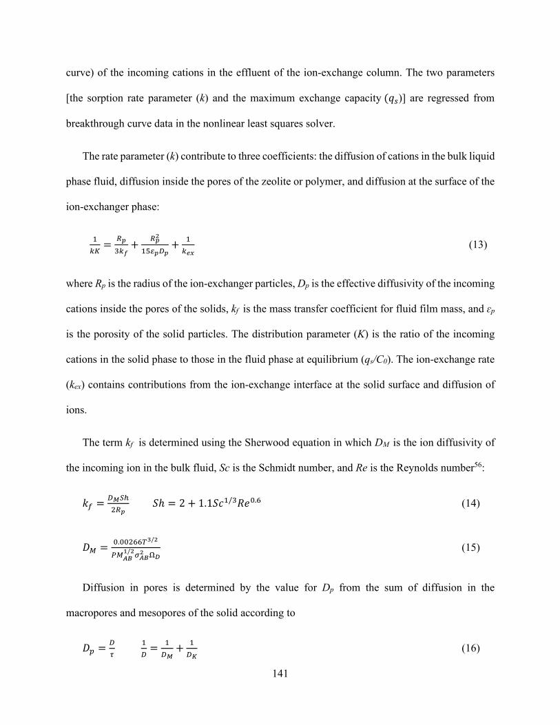
141
curve) of the incoming cations in the effluent of the ion-exchange column. The two parameters
[the sorption rate parameter (k) and the maximum exchange capacity (𝑞𝑞𝑎𝑎)] are regressed from
breakthrough curve data in the nonlinear least squares solver.
The rate parameter (k) contribute to three coefficients: the diffusion of cations in the bulk liquid
phase fluid, diffusion inside the pores of the zeolite or polymer, and diffusion at the surface of the
ion-exchanger phase:
1𝑘𝑘𝐾𝐾
= 𝑅𝑅𝑖𝑖3𝑘𝑘𝑓𝑓
+ 𝑅𝑅𝑖𝑖2
15𝜀𝜀𝑖𝑖𝐷𝐷𝑖𝑖+ 1
𝑘𝑘𝑒𝑒𝑚𝑚 (13)
where Rp is the radius of the ion-exchanger particles, Dp is the effective diffusivity of the incoming
cations inside the pores of the solids, kf is the mass transfer coefficient for fluid film mass, and ɛp
is the porosity of the solid particles. The distribution parameter (K) is the ratio of the incoming
cations in the solid phase to those in the fluid phase at equilibrium (qs/C0). The ion-exchange rate
(kex) contains contributions from the ion-exchange interface at the solid surface and diffusion of
ions.
The term kf is determined using the Sherwood equation in which DM is the ion diffusivity of
the incoming ion in the bulk fluid, Sc is the Schmidt number, and Re is the Reynolds number56:
𝑘𝑘𝑜𝑜 = 𝐷𝐷𝑀𝑀𝑆𝑆ℎ2𝑅𝑅𝑖𝑖
𝑆𝑆ℎ = 2 + 1.1𝑆𝑆𝑐𝑐1/3𝑅𝑅𝑐𝑐0.6 (14)
𝐷𝐷𝑀𝑀 = 0.00266𝑇𝑇3/2
𝑃𝑃𝑀𝑀𝐴𝐴𝐴𝐴1/2𝜎𝜎𝐴𝐴𝐴𝐴
2 Ω𝐷𝐷 (15)
Diffusion in pores is determined by the value for Dp from the sum of diffusion in the
macropores and mesopores of the solid according to
𝐷𝐷𝑎𝑎 = 𝐷𝐷𝜏𝜏
1𝐷𝐷
= 1𝐷𝐷𝑀𝑀
+ 1𝐷𝐷𝐾𝐾
(16)

142
where DK is the Knudsen diffusivity given by 𝐷𝐷𝐾𝐾 = 9700𝑟𝑟(𝑇𝑇𝑀𝑀
)1/2 (r is the pore radius, T is
temperature, and M is the molecular weight of the diffusing species), and τ is the tortuosity.
5.3.4.2 Kinetic Sorption Modeling for Batch Experiments
5.3.4.2.1 Pseudo-First Order
The equation of pseudo-first order is as follows57:
𝑞𝑞 = 𝑞𝑞𝑒𝑒[1 − 𝑐𝑐𝑥𝑥𝑒𝑒(−𝑘𝑘1𝑡𝑡)] (17)
𝑑𝑑𝑞𝑞𝑏𝑏𝑑𝑑𝑎𝑎
= 𝑘𝑘1 × (𝑞𝑞𝑒𝑒 − 𝑞𝑞𝑎𝑎) (18)
𝑚𝑚𝑚𝑚𝑔𝑔(𝑞𝑞𝑒𝑒 − 𝑞𝑞𝑎𝑎) = log 𝑞𝑞𝑒𝑒 −𝑘𝑘1
2.303× 𝑡𝑡 (19)
where 𝑞𝑞 is the number of ions exchanged, 𝑞𝑞𝑒𝑒 is the number of ions at equilibrium, and 𝑘𝑘1 is the
pseudo-first order rate constant.
5.3.4.2.2 Pseudo-Second Order
The equation of pseudo-second is as follows58:
𝑞𝑞 = 𝑎𝑎1
𝑘𝑘2𝑞𝑞𝑒𝑒2+ 𝑏𝑏𝑞𝑞𝑒𝑒
(20)
𝑑𝑑𝑞𝑞𝑏𝑏𝑑𝑑𝑎𝑎
= 𝑘𝑘1 × (𝑞𝑞𝑒𝑒 − 𝑞𝑞𝑎𝑎)2 (21)
𝑞𝑞𝑏𝑏𝑎𝑎
= 1𝑘𝑘1×𝑞𝑞𝑒𝑒2
+ 𝑎𝑎𝑞𝑞𝑒𝑒
(22)
where 𝑘𝑘2 is the pseudo-second order rate constant.

143
The terms 𝑘𝑘1 and 𝑘𝑘2 are the rate constants for the pseudo-first and pseudo-second order
equations, and 𝑞𝑞𝑒𝑒 and 𝑞𝑞𝑎𝑎 are uptake mmol per weight unit of the sorbent at equilibrium and at time
t, respectively.59 Plotting 𝑚𝑚𝑚𝑚𝑔𝑔𝑘𝑘2 as a function of 1/T is useful to obtain the activation energy (𝐸𝐸𝑎𝑎)
using the Arrhenius equation:
𝑘𝑘 = 𝐴𝐴 × 𝑐𝑐−(𝐸𝐸𝑚𝑚𝑆𝑆 ×𝑇𝑇) (23)
where 𝑘𝑘 is the rate coefficient, 𝐴𝐴 is constant, 𝐸𝐸𝑎𝑎 is the activation energy, 𝑅𝑅 is the universal
gas constant, and T is the temperature (in Kelvin). Activation energy values between 5 and 20 kJ
mol−1 characterize the sorption process and are controlled by diffusion, and the chemical reaction–
controlled process requires more than 20 kJ mole−1 energy.60,61

144
5.4 Results and Discussion
5.4.1 Selection of Ion-Exchange Materials
In the preliminary studies, different chelating ion exchangers containing such functional
groups as iminodiacetate (Lewatit TP 207), aminomethyl phosphonate (Lewatit TP 260), sulfonic
groups (Amberlite 200 C, Lewatit MonoPlus SP 112, Diaion SK112, and Amberlite IR120), and
zeolites (13X, 4A) were used. The proton uptake by ion-exchange materials was studied by varying
the amount of the ion exchanger from 0.25 to 5.0 g while keeping the other parameters such as pH
(4), solution volume (20 mL), agitation speed (0 rpm), and proton concentration (64 mmol/L)
constant. The H+–Na+ ion exchange was conducted in CO2-saturated water (pCO2 = 1 atm, pH 4;
Figure 5.2). As the water equilibrated with the CO2 gas stream, dissolved CO2 acidified the water
by forming H2CO3. As the H+ concentration in the water increased, it exchanged with monovalent
ions contained in the ion-exchanger solid (Na+) until equilibrium was achieved, which prevented
a further increase in pH. The achievement of equilibrium was checked by taking repeated samples
as well as by letting the system approach the equilibrium state. Liquid samples were withdrawn
and analyzed by ICP-OES. The pH and sodium concentration of the solution after equilibrium was
reached were also determined.

145
Figure 5.2. Effect of material solid loading on the pH of materials.
Increasing the ratio of the solid to liquid resulted in increasing proton removal. The increase
in pH with the increasing solid-to-liquid ratio was due to the larger surface sites numbers accessible
for interaction. In all ion-exchange materials, as pH increase, it was coupled also with an increase
in concentration of Na, demonstrating the feasibility of the forward ion-exchange process and
illustrating that significant basicity can be generated. The cationic resins that contained sulfonic
groups (Amberlite 200 C) did not achieve high proton removal percentages (i.e., the pH did not
meet the minimum pH = 8 required for calcium carbonate precipitation). Amberlite IR-120, Diaion
SK112, and Lewatit Mono Plus SP 112 obtained unsatisfactory results, with maximum obtained
pH values equal to 6, 5.5 , and 7, respectively.
Compared with the strongly acidic ion exchange materials, weakly acidic resins exhibited
higher ion-exchange capacity and higher affinity for protons. The affinity of the ion exchanger to
dissociate sodium and exchange it with a proton was higher for the weak acidic cation exchange
resin than for the strong acidic resin. Strong acid resin is highly dissociated; thus, a considerable
excess of acid is needed to convert the sodium form into the hydrogen form. Strongly acidic
material imposes lower ion-exchange potential performance than does the weakly acidic resin.
Weak-to-moderate acidic ion exchangers, such as zeolite (13X and 4A), have less hydrogen
affinity than weakly acidic resin does but are able to convert dissolved carbonic acid into NaHCO3.
Lewatit TP 207(Na) and Lewatit 260 were superior in terms of ion exchange and increasing
the alkalinity of the solution from 4 to approximately 10. They were followed by weak ion
exchangers such as zeolite 13X and 4A. Thus, in the next stages, the following ion exchangers
were investigated: Lewatit TP 207 and Lewatit TP 260, zeolite 13X, and zeolite 4A. Lewatit TP

146
207 and Lewatit TP 260 resins are both weakly acidic and in the Na+ form but contain different
active groups. In the case of Lewatit TP 260 resin, the proton uptake was higher than that exhibited
in TP 207. TP 260 is a weak acidic macroporous resin that contains chelating
aminomethylphosphonic acid groups.62 The aminomethylphosphonic acid group is a tridentate
ligand that has two connection sites attached to phosphonic acid group and one coordination site
at the nitrogen atom. Depending on the pH, the aminomethylphosphonic acid chelating group
occurs in the forms shown in Figure 5.3. The presence of the methylene group increases the
electron density on the atom of nitrogen of the amine groups, which promotes its protonation.63–66
Lewatit TP 207 is a weakly acidic resin with chelating iminodiacetate.66 At low pH, the excess
proton competes for the binding site. When pH increases, the H+ is displaced from the functional
group of the resin, allowing ion exchange to occur in the resin. The pH values dictate the
occurrence of iminodiacetate groups in the forms presented in Figure 5.4.67,68 At pH values of
approximately 2 (or less), both carboxylic groups and nitrogen atoms occur in the protonated
forms. At higher pH (∼12), both carboxylic groups are deprotonated, and the ion exchanger
behaves as a typical cation exchanger. The number of cations exchanged at low pH values is lower
than the number of ions exchanged at high pH values. This is due to the iminodiacetic functional
groups of the resin, which tend to remain protonated in low pH solutions, and thus, the ions are
less preferred by the resin under these conditions.69–71

147
Figure 5.3. Aminomethylphosphonic acid chelating groups that occur (drawing made using MarvinSketch).63–66
Figure 5.4. Iminodiacetate groups that occur in Lewatit TP 207 (drawing made using MarvinSketch).67,68

148
The ion exchanger was also able to increase the pH of the natural pH water. The rise in pH
was attributed to the exchange between Na+ and H+ from the water solution (Figure 5.5). This
shows that the ion-exchange process can also be used to increase the pH of deionized (DI) water
before adding the CO2 to the solution, which is an alternative to the previous step in which CO2
was initially equilibrated with the solution before ion-exchange materials were added. When 1 g
of NaR (where R is the exchanger matrix) was added into 20 mL of DI water, a small amount of
Na+ was released, and the pH became alkaline. This indicated that Na+ was retained to compensate
for the negative charge of zeolite that was released to the aqueous phase, followed by H+ uptake,
which originated for the dissociation of water.
The ion speciation of hydrolysable ions changes with changes in pH levels. Hydrolysis is
a common phenomenon with inorganic and weakly acidic organic ion exchangers. In a hydrolysis
reaction, the exchanger (NaR, where R is the exchanger matrix) takes up proton ions from water.72
The more selective the exchanger for hydronium ions is (i.e., the more weakly acidic the exchanger
is), the more pronounced it is for hydrolysis. Hydrolysis increases the pH and alters the ionic
composition of dilute solutions. The resulting carbonic acid consumes the hydroxyl ions that are
produced by hydrolysis to yield HCO3− and CO3
2− in solution. Thus, The H+–Na+ ion exchange
was conducted in neutral water (pCO2 = 400 ppm, pH 7). As the solid load increases, basicity
increases toward a maximum of 12.
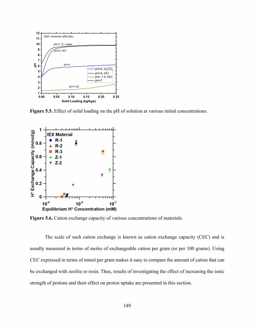
149
Figure 5.5. Effect of solid loading on the pH of solution at various initial concentrations.
Figure 5.6. Cation exchange capacity of various concentrations of materials.
The scale of such cation exchange is known as cation exchange capacity (CEC) and is
usually measured in terms of moles of exchangeable cation per gram (or per 100 grams). Using
CEC expressed in terms of mmol per gram makes it easy to compare the amount of cation that can
be exchanged with zeolite or resin. Thus, results of investigating the effect of increasing the ionic
strength of protons and their effect on proton uptake are presented in this section.
0.00 0.05 0.10 0.15 0.20 0.25123456789
101112
pH
Solid Loading (kg/kgw)
pH=4, H2CO3
pH=4, HCl pH= 1.5, HCl pH=7
pH=7, D.I. water
pH=4, HCl
pH=1.52
pH=4
200C Amberlite 200C(Na)

150
Equilibrium uptake isotherms were collected for the batch equilibrium experiments. Figure
5.6 shows the exchange capacities of the ion-exchange materials in various concentrations of HCl
solutions and CO2-saturated solutions. CO2 concentrations by volume from point sources are
roughly 3% for natural gas–fired power plants; 15% for coal-fired power plants and iron and steel
mills; 20% for cement plants; and >90% for ammonia, ethanol, and hydrogen plants.73 Therefore,
we used the reference concentrations of 5%, 20%, and 100% in the above analysis. In this case,
the total number of cations in the systems was supposedly constant using 1 g of an ion exchanger.
Changing the concentration of CO2 from 15% to 100% resulted in lower equilibrium
concentrations and thus lower exchange capacities. The maximum exchange capacity was
achieved at the initial CO2 concentration of 14% with 2.1 mmol/g. This follows the same trend
observed with Na+/H+ exchange in HCl solutions. Maximum exchange capacity with organic
exchange resin was achieved at 1 M HCl (~3 mmol/g Na released) with a high Na release from the
zeolites due to dissolution. Overall, weakly acidic function groups provided higher ion-exchange
capacities than zeolitic materials did; this may have been a result of the available exchange sites
and hydrogen affinity. Zeolite Na-X had a CEC of 0.6 mmol g−1. It had a lower exchange capacity
than did Na-A and did not proceed to a full exchange. Exchange capacity was higher than solid
loading but lower than the HCl experiment’s exchange capacity. This is because HCl represented
the highest exchange capacity so far.

151
5.4.2 Ion-Exchange Selectivity
Produced water contains various types of polyvalent cations that can inhibit ion exchange
and compete with and affect the sorption behavior of ion-exchange materials for H+ uptake.
Therefore, it was essential to investigate the effect of coexisting ions on H+ uptake. Single and
binary component exchange isotherms were collected to probe the selectivity for the exchange of
Na+ with H+ in the presence of produced water ions, such as Ca2+ and Mg2+. The organic cation
exchange resins used in this study have a high affinity for divalent cations because of their
chelating-like functional groups. These resins are commonly used for water hardness removal (i.e.,
removal of Ca and Mg ions from water) because of their high affinities for divalent cations. Their
high affinities for divalent cations may hinder H+ uptake when using a produced water feed for
swinging the pH. In quantifying the effect on H+ uptake due to the presence of calcium cations,
the most prominent divalent cation found in produced water streams, for all materials, determines
the composition of the feed stream required to swing the pH of a stream containing CO2. Shown
in Figure 5.7 a and b is the effect of calcium in solution on H+ uptake within HCl- and CO2-
saturated water, respectively.
(a) (b)

152
Figure 5.7. H+ uptake reduction as a function of equilibrium calcium concentrations increasing in solution in (a) HCl and (b) saturated CO2 solution.
The ion-exchange capacity for H+ appears to be very similar to that of Ca2+ at a low
concentration of Ca2+ in the solution for both HCl- and CO2-saturated solutions. A similar capacity
suggests that there is no significant selectivity of Ca2+ over H+. However, as the concentration of
Ca2+ increased in the solution, the uptake of H+ started to decrease, reaching minimum levels when
the concentration of Ca2+ increased over 10−3 (mol/L). Divalent cation uptake is only hindered by
the presence of other divalent cations or large concentrations of monovalent ions. The increase can
be explained by decreased competition between protons and Ca2+ for the same functional group
and by a decrease in the positive surface charge in resin resulting in lower electrostatic repulsion
between the surface of resin and calcium or magnesium ions.74 Selectivity could be the result of
several factors that affect ion-exchange behavior in the zeolite and resin. One factor is the structure
of the zeolite; the dimensions of channels formed by tetrahedral units need to be large enough to
allow hydrated ions to approach active sites. The specificity of a surface containing fixed charges
for alkali ions was accounted for in terms of ion hydration and electrostatic bond energies.75 The
metal-binding strength increases as the radius of the hydrated metal ion decreases and the charge
of the metal ion increases. A strong electrostatic field effect may become the dominant factor for
ion affinity, such that small ions with a higher charge density are bound more strongly. An
alternative explanation for the difference in selectivity involving two ions with the same radius is
the dehydration phenomena,76 in which hydrated ions initially overcome the energy barrier to be
able to enter zeolite channels. This energy barrier is mainly composed of the energy required to
dehydrate ions during collusion at the pore entrance.

153
As shown in Figure 5.7 a and b, the divalent cations found in produced water had a
detrimental effect on the ion-exchange process, resulting in a decrease in H+ uptake efficiency.
These ions have a stronger attraction to the active site than an H+. H+ uptake decreased with
increasing equilibrium calcium concentrations because of the higher affinity for divalent cations
of the ion-exchange materials. Due to the higher affinities for divalent cations, it was difficult to
develop a pH swing process using an integrated process configuration (i.e., carbonation reactor
integrated with an ion-exchange process).
5.4.3 Batch Kinetic Results
The kinetics of ion exchange describe the rate of ion uptake on the ion-exchange resin and
zeolites, and this rate controls the equilibrium time. The kinetic factor is required to select optimum
operating conditions for a full-scale batch process. To evaluate the differences in the ion-exchange
kinetic rates and the ion recoveries, the kinetics of ion uptake were described with a pseudo-first
order and pseudo-second order model. The pseudo-first order model assumes a diffusion-
controlled process inside the particles, whereas the pseudo-second order model assumes that the
process is controlled by ion exchange at liquid–solid interface in the adsorbent.77,78 The results of
the sorption kinetics experiments for the zeolites studied are presented in Figure 5.8. For the
zeolites studied, the sorption process was rapid. Zeolite 13X had the fastest sorption due to its large
pore structure and slow diffusion. Equilibrium was reached after 3 h (1.2 mmol/g). For 4A,
equilibrium was achieved after 16 h. The results revealed a faster kinetic rate for the organic
polymer.
The diffusion rate of the ion exchanger can be limited with the interdiffusion of the
exchanged counterions within the ion exchanger (i.e., particle diffusion) or with an adjacent liquid
film that is not affected by the agitation of the solution (i.e., film diffusion). Large crystals, such

154
as 13X, were compared to 4A and exhibited a similar rate of release of Na+, indicating that this
release was not particle diffusion control (Figure 5.8; Table 5.2 and 5.3).
The kinetic experiments of ion exchange in zeolite indicated slower exchange rates for
larger crystallites. Zeolite has a subnanometer porous structure that involves mechanisms of ion
transport other than nonporous polymer resin. Due to the space confinement in the channels and
strong interactions between water, ions, and pore surface, the mobility of water and ions are
mutually affected. As shown in Figure 5.8, the exchange of Na+ with H+ proceeds faster with the
smaller crystallites (4A), whereas their ion-exchange equilibrium is identical. With smaller pores,
a faster exchange is observed.79 A kinetic exchange between cations diffusing through the
micropores and cations bound to a specific site could be the rate-determining step. However, this
requires that the rate of exchange of ions at sites within the zeolite channels is slower than the rate
at which ions diffuse through the micropores.
The chemical exchange reaction at fixed ionic sites is not the rate-limiting step. Several
studies have shown that the Na+/H+ exchange reaction in natural solution is rapid, and equilibrium
is attainable within a few minutes.80,81 Furthermore, the kinetic reaction is not a first-order
reaction.82 To confirm the fast exchange process, kinetic experiments were carried out at
temperatures of 5 °C, 25 °C, and 50 °C (Figure 5.8). A distinct positive effect of temperature on
the sorption rate was observed in addition to exchange capacity. The constant rate k2 for
temperatures of 5 °C to 50 °C indicated that higher temperatures favor the driving force of the
exchange process, and it increased from 0.027 to 0.040 (mmol/min) for TP207, from 0.011 to
0.017 (mmol/min) for TP260, from 0.016 to 0.029 (mmol/min) for 4A, and from 0.012 to 0.016
(mmol/min) for 13X. The activation energy was determined from the slope of a linear plot. The
values calculated were less than 20 kJ mol−1 (Table 5.4), which may indicate the diffusion-limited

155
process. Generally, activation energy values between 5 to 20 kJ mol−1 characterize the ion-
exchange process that is controlled by diffusion, while the chemical reaction–controlled process
requires more than 20 kJ mole−1 of energy.60,61
The increase in ion exchange with temperature may be attributed to the increasing rate of
the intraparticle diffusion of ions into pores that are adsorbent at higher temperatures. If the
interdiffusion of exchangeable species in solid or bulk solution is the rate-determining step, then
the rate constant will be equal when static and mixing and independent of mixing. Under
convective mixing, the ion-exchange rate increases exponentially with an increase in mixing
speed. This signifies the importance of the role of transport in ion exchange. At a strong mixing
rate, the resistance of the boundary layer that surrounds the sorbents weakens. As can be observed
by the k2 constant, the ion-exchange rate is faster at a higher mixing rate. In solid-state exchange
reactions, a small amount of water can increase the speed of the reaction.83 Therefore, the ion-
exchange reaction has been modeled as diffusion limited.84 When diffusion is the rate-controlling
step, then the rate-controlling diffusion process may not be within the micropores themselves but
instead may be limited by transport via a near-static boundary layer that is inserted between the
external solution and crystalline surface. This process is described as a film or boundary layer
diffusion.85
In our results, weakly ionic resins, such as TP207 and 260 kinetics, were significantly
enhanced by mixing but were not when remaining static, which suggests a surface-controlled
reaction. This was proved to be correct because we did not have any pores that could limit the
diffusion. By contrast, data for 4A and 13X were not significantly affected by mixing, which may
suggest a solid-phase diffusion-controlled mechanism. Furthermore, the static and mixed solution
conditions led to the same activation energy; hence, the diffusion of ions through the Nernst’s

156
diffusion layer is the rate-limiting step. This is because solution viscosity would not influence ion
transport.
101 102 103 1040.0
0.1
0.2
0.3
0.4
0.5
0.6
0.7
0.8
207 Static Kinetics 5°C 25°C 50°C
Aqu
eous
[Na+ ]
(mm
ol/L
)
Reaction Time, t (min)101 102 103 104
0.1
0.2
0.3
0.4
0.5
0.6207 Convective Kinetics
5°C 25°C 50°C
Aqu
eous
[Na+ ]
(mm
ol)
Reaction Time, t (min)
101 102 103 1040.0
0.1
0.2
0.3
0.4
0.5
0.6
0.7
0.8260 Kinetics
5°C 25°C 50°C
Aqu
eous
[Na+ ]
(mm
ol)
Reaction Time, t (min)101 102 103 104
0.1
0.2
0.3
0.4
0.5
0.6
0.7260 Convective Kinetics
5°C 25°C 50°C
Aqu
eous
[Na+ ]
(mm
ol)
Reaction Time, t (min)
101 102 103 1040.0
0.1
0.2
0.3
0.4
0.5
0.613X Static Kinetics
5°C 25°C 50°C
Aqu
eous
[Na+ ]
(mm
ol)
Reaction Time, t (min)101 102 103 104
0.0
0.1
0.2
0.3
0.4
0.513X Convective Kinetics
5°C 25°C 50°C
Aqu
eous
[Na+ ]
(mm
ol)
Reaction Time, t (min)

157
Figure 5.8. Na+ release and exchange with H+ from solution as functions of time for TP207, TP260, 4A, and 13X undergoing ion exchange under static and convective (stirred) mixing conditions for an initial CO2 concentration of 34 mmol/L.
Table 5.2. Ion exchange reactions for different materials over time from 5 °C to 50 °C under static conditions.
Material TP-207 TP-260 Zeolite 4A Zeolite 13X
Temperature (°C)
K (mmol/min)
K (mmol/min)
K (mmol/min)
K (mmol/min)
5 0.027 0.011 0.016 0.012
25 0.030 0.013 0.022 0.014
50 0.040 0.017 0.029 0.016
Table 5.3. Ion exchange reactions for different materials over time from 5 °C to 50 °C under convective conditions.
Material TP-207 TP-260 Zeolite 4A Zeolite 13X
Temperature (°C)
K (mmol/min)
K (mmol/min)
K (mmol/min)
K (mmol/min)
5 0.015 0.009 0.015 0.020
25 0.032 0.060 0.027 0.065
50 0.045 0.12 0.035 0.024
101 102 103 1040.0
0.1
0.2
0.3
0.4
0.5
0.6
0.7
4A Static Kinetics 5°C 25°C 50°C
Aqu
eous
[Na+ ]
(mm
ol)
Reaction Time, t (min)100 101 102 103 104
0.0
0.1
0.2
0.3
0.44A Convective Kinetics
5°C 25°C 50°C
Aqu
eous
[Na+ ]
(mm
ol)
Reaction Time, t (min)

158
Table 5.4. Activation enthalpies of ion-exchange reactions for materials.
Material ΔH (kJ/mol) Static
ΔH (kJ/mol) Convective
TP-207 ---- 17.4
TP-260 6.6 43
Zeolite 4A 9.5 9.9
Zeolite 13X 4.9 ----
5.4.4 Polyvalent Ion-Exchange Kinetics
The results obtained for calcium, magnesium, and iron kinetics indicate a different
mechanism from that for Ca/Mg uptake. In general, the amount of sodium released materials and
exchanged with ions from solutionis higher for Ca/Mg than for that of Fe. Figures 5.9–5.11 show
the kinetics of metal exchange with ion-exchange materials. The plots represent the rate of ion
exchange over time, showing the amount of sodium release as it is exchanged by the ions placed
in the solution, whether Ca, Mg, or Fe. Although ions started initially with the same concentration,
Tables 5.5–5.7 show the correlation coefficients of the kinetic first-order (first order) and pseudo-
second order (second order) models for Ca2+, Mg2+, and Fe3+ sorption on the four materials and
their exchange with Na+ attached to the functional groups of these materials. In all materials, the
first-order equation of Lagergren did not apply well throughout the entire range of contact times,
which can be seen in Figures 5.9–5.11. Results presented in Tables 5.5 and 5.6 show faster kinetics
for Mg2+ (4.7E-02, 4.3E-02, 5.2E-03, 5.32E-2 mmol/g for TP207, TP260, 4A and 13X,
respectively) compared with Ca2+ (3.23E-03, 4.91E-03, 1.48E-02, 6.78E-3 mmol/g for TP207,
TP260, 4A, and 13X, respectively). The slow rate of Ca2+ ion exchange compared to Mg2+ is
primarily attributed to the smaller hydration energy of the Ca2+ ion. This ion has approximately
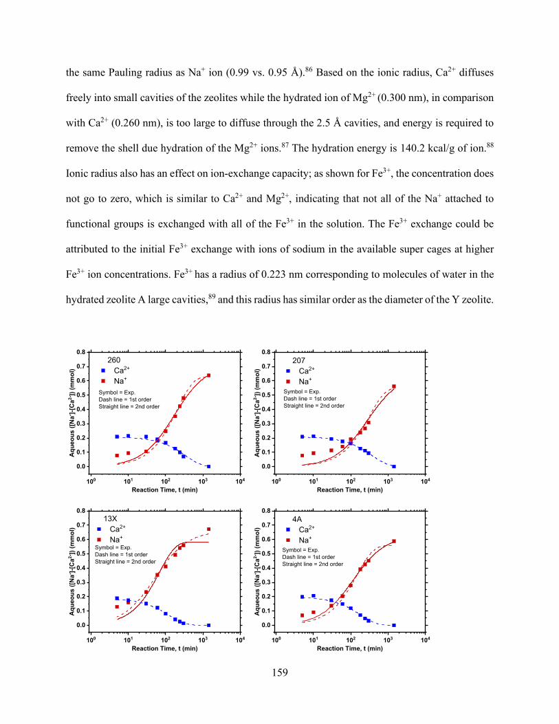
159
the same Pauling radius as Na+ ion (0.99 vs. 0.95 Å).86 Based on the ionic radius, Ca2+ diffuses
freely into small cavities of the zeolites while the hydrated ion of Mg2+ (0.300 nm), in comparison
with Ca2+ (0.260 nm), is too large to diffuse through the 2.5 Å cavities, and energy is required to
remove the shell due hydration of the Mg2+ ions.87 The hydration energy is 140.2 kcal/g of ion.88
Ionic radius also has an effect on ion-exchange capacity; as shown for Fe3+, the concentration does
not go to zero, which is similar to Ca2+ and Mg2+, indicating that not all of the Na+ attached to
functional groups is exchanged with all of the Fe3+ in the solution. The Fe3+ exchange could be
attributed to the initial Fe3+ exchange with ions of sodium in the available super cages at higher
Fe3+ ion concentrations. Fe3+ has a radius of 0.223 nm corresponding to molecules of water in the
hydrated zeolite A large cavities,89 and this radius has similar order as the diameter of the Y zeolite.
100 101 102 103 104
0.0
0.1
0.2
0.3
0.4
0.5
0.6
0.7
0.8 260
Ca2+
Na+
Aqu
eous
([N
a+ ]-[C
a2+])
(mm
ol)
Reaction Time, t (min)
Symbol = Exp.Dash line = 1st order Straight line = 2nd order
100 101 102 103 104
0.0
0.1
0.2
0.3
0.4
0.5
0.6
0.7
0.8 207
Ca2+
Na+
Aqu
eous
([N
a+ ]-[C
a2+])
(mm
ol)
Reaction Time, t (min)
Symbol = Exp.Dash line = 1st order Straight line = 2nd order
100 101 102 103 104
0.0
0.1
0.2
0.3
0.4
0.5
0.6
0.7
0.8 13X
Ca2+
Na+
Aqu
eous
([N
a+ ]-[C
a2+])
(mm
ol)
Reaction Time, t (min)
Symbol = Exp.Dash line = 1st order Straight line = 2nd order
100 101 102 103 104
0.0
0.1
0.2
0.3
0.4
0.5
0.6
0.7
0.8 4A
Ca2+
Na+
Aqu
eous
([N
a+ ]-[C
a2+])
(mm
ol)
Reaction Time, t (min)
Symbol = Exp.Dash line = 1st order Straight line = 2nd order

160
Figure 5.9. Na+ exchanged by Ca2+ concentrations as functions of time for TP207, TP260, 4A, and 13X undergoing ion exchange under static conditions.
Figure 5.10. Na+ exchanged by Mg2+ concentrations as functions of time for TP207, TP260, 4A, and 13X undergoing ion exchange under static conditions.
101 102 103
0.0
0.1
0.2
0.3
0.4
0.5
0.6
0.7
0.8
Symbol = Exp.Dash line = 1st order Straight line = 2nd order
4A Mg2+
Na+
Aqu
eous
([N
a+ ]-[M
g2+])
(mm
ol)
Reaction Time, t (min)100 101 102 103 104
0.0
0.1
0.2
0.3
0.4
0.5
0.6
0.7
0.8
13X Mg2+
Na+
Aqu
eous
([N
a+ ]-[M
g2+])
(mm
ol)
Reaction Time, t (min)
Symbol = Exp.Dash line = 1st order Straight line = 2nd order
100 101 102 103 104
0.0
0.1
0.2
0.3
0.4
0.5
0.6
0.7
0.8 207
Na+
Mg2+
Aqu
eous
([N
a+ ]-[M
g2+])
(mm
ol)
Reaction Time, t (min)
Symbol = Exp.Dash line = 1st order Straight line = 2nd order
100 101 102 103 104
0.0
0.1
0.2
0.3
0.4
0.5
0.6
0.7
0.8
260 Mg2+
Na+
Aqu
eous
([N
a+ ]-[M
g2+])
(mm
ol)
Reaction Time, t (min)
Symbol = Exp.Dash line = 1st order Straight line = 2nd order
100 101 102 103 104
0.0
0.1
0.2
0.3
0.4
0.5
0.6
0.7
0.8 4A
Fe3+
Na+
Aqu
eous
([N
a+ ]-[Fe
3+])
(mm
ol)
Reaction Time, t (min)
Symbol = Exp.Dash line = 1st order Straight line = 2nd order
100 101 102 103 104
0.0
0.1
0.2
0.3
0.4
0.5
0.6
0.7
0.8 13X
Fe3+
Na+
Aqu
eous
([N
a+ ]-[Fe
3+])
(mm
ol)
Reaction Time, t (min)
Symbol = Exp.Dash line = 1st order Straight line = 2nd order

161
Figure 5.11. Na+ exchanged by Fe3+ concentrations as functions of time for TP207, TP260, 4A, and 13X undergoing ion exchange under static conditions.
Table 5.5. Correlation coefficients of the kinetic pseudo-first-order (first order) and pseudo-second-order (second order) models for Ca2+ sorption on the four materials.
Material First order, kNa
(mmol/g) Second order, kNa (mmol/g)
First order, kCa (mmol/g)
207 3.23E-03 5.51E-03 2.01E-01
260 4.91E-03 8.82E-03 2.92E-03
4A 1.48E-02 2.91E-02 1.88E-01
13X 6.78E-03 1.39E-02 1.99E-01
Table 5.6. Correlation coefficients of the kinetic pseudo-first-order (first order) and pseudo-second-order (second order) models for Mg2+ sorption on the four materials.
Material First order, kNa
(mmol/g) Second order, kNa (mmol/g)
First order, kCa (mmol/g)
207 4.7E-02 - -
260 4.3E-02 - -
4A 5.2E-03 - -
100 101 102 103 104
0.0
0.1
0.2
0.3
0.4
0.5
0.6
0.7
0.8 260
Fe3+
Na+
Aqu
eous
([N
a+ ]-[Fe
3+])
(mm
ol)
Reaction Time, t (min)
Symbol = Exp.Dash line = 1st order Straight line = 2nd order
100 101 102 103 104
0.0
0.1
0.2
0.3
0.4
0.5
0.6
0.7
0.8 207
Fe3+
Na+
Aqu
eous
([N
a+ ]-[Fe
3+])
(mm
ol)
Reaction Time, t (min)
Symbol = Exp.Dash line = 1st order Straight line = 2nd order

162
13X 5.32E-2 - -
Table 5.7. Correlation coefficients of the kinetic pseudo-first-order (first order) and pseudo-second-order (second order) models for Fe3+ sorption on the four materials.
Material First order, kNa (mmol/g)
Second order, kNa (mmol/g)
First order, kFe
(mmol/g)
207 9.52E-03 4.74E-02 2.03E-01
260 1.39E-02 7.48E-02 2.09E-01
4A 3.79E-03 1.27E-02 2.08E-01
13X 6.60E-03 2.49E-02 2.07E-01
5.4.5 Column Experiments
Bohart-Adams is a simple model that combine bulk partial differential equation in time and
in distance with a rate expression that describe the pickup (exchange capacity in ion exchange
case) and in a rate expression called linear drive force model which assumes the pickup is linear
allowing the estimation of two parameter model which are maximum capacity (𝑞𝑞𝑎𝑎) and average
sorption rate (𝑘𝑘) and all of the things that could delay the pickup is summed in one parameter. The
model was analyzed by changing the flow rate to evaluate the efficiency of ion-exchange materials
in a continuous process. The effect of varying flow rate on H+ uptake capacities and ion exchange
diffusion parameters in saturated CO2, with no other cations present besides H+ from the carbonic
acid (H2CO3), feeds were quantified at flow rates from 20–60 SCCM. As shown in Figure 5.12, at
lower flow rates, higher exchange capacity is achieved consistently for all ion-exchange materials.
This may be a result of the increase in the speed of the ion exchange zone with increasing flow
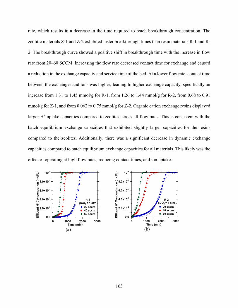
163
rate, which results in a decrease in the time required to reach breakthrough concentration. The
zeolitic materials Z-1 and Z-2 exhibited faster breakthrough times than resin materials R-1 and R-
2. The breakthrough curve showed a positive shift in breakthrough time with the increase in flow
rate from 20–60 SCCM. Increasing the flow rate decreased contact time for exchange and caused
a reduction in the exchange capacity and service time of the bed. At a lower flow rate, contact time
between the exchanger and ions was higher, leading to higher exchange capacity, specifically an
increase from 1.31 to 1.45 mmol/g for R-1, from 1.26 to 1.44 mmol/g for R-2, from 0.68 to 0.91
mmol/g for Z-1, and from 0.062 to 0.75 mmol/g for Z-2. Organic cation exchange resins displayed
larger H+ uptake capacities compared to zeolites across all flow rates. This is consistent with the
batch equilibrium exchange capacities that exhibited slightly larger capacities for the resins
compared to the zeolites. Additionally, there was a significant decrease in dynamic exchange
capacities compared to batch equilibrium exchange capacities for all materials. This likely was the
effect of operating at high flow rates, reducing contact times, and ion uptake.
(a)
(b)

164
(c)
(d)
Figure 5.12. Breakthrough curves for the alkalinity-inducing reaction at different flow rates for (a) R-1 (TP 207), (b) R-2 (TP 260), (c) Z-1 (Zeolite 4A), and (d) Z-2 (Zeolite 13X). Dashed lines represent Bohart–Adams model predictions for breakthrough curves.
As the flow rate increases, so does the Reynolds number (𝑅𝑅𝑐𝑐), furthermore 𝑅𝑅𝑐𝑐 directly
proportional to the Sherwood number (𝑆𝑆ℎ), and the mass transfer coefficient is directly
proportional to the 𝑆𝑆ℎ number. Therefore, when 𝑅𝑅𝑐𝑐 increases, the 𝑆𝑆ℎ increases, and then the mass
transfer number increases. The Peclet number increases with the Reynolds number and with flow
rate. Increasing the Péclet number (Pe) number makes the breakthrough steeper.
According to Eq. 13, there are have three resistances for the kinetics of ions throughout the
ion exchange process, and one of these resistances should be the rate-limiting step; as indicated
previously, the ion exchange process in this study is not an ion exchange limited process (the ion
exchange between Na+ from solids and ions from the liquid is much faster than either the diffusion
in bulk of liquid or throughout the film) because ion exchange is very fast. The parameter defined
in equation 13 for the radius (𝑅𝑅𝑎𝑎) is inversely proportional to the overall transfer coefficient (𝑘𝑘𝐾𝐾)
which means that smaller pore size give higher transfer coefficient and higher kinetic. The other
factor within the film transfer coefficient (𝑘𝑘𝑜𝑜), is directly proportional to Dm (diffusivity which is
related to ion diffusion property) and we have 𝑆𝑆ℎ is directly proportional to 𝑅𝑅𝑐𝑐 and flow rate

165
Therefore, higher flow rate increases 𝑅𝑅𝑐𝑐 which in turn increase 𝑆𝑆ℎ that increase 𝑘𝑘𝑜𝑜 which is
directly proportional to the overall transfer coefficient (𝑘𝑘𝐾𝐾). Then, higher 𝑘𝑘𝑜𝑜 gives higher 𝑘𝑘𝐾𝐾 value
and higher kinetics is associated with higher flow rate (Table 5.8).
Table 5.8. Bohart–Adams parameters for the materials used in this study at varying flow rates in the column ion-exchange process.
Material Flow Rate (SCCM) 𝑞𝑞𝑎𝑎 [H+ Uptake Capacities] (mmol/g)
𝑘𝑘 (cm3/mmol/s)
R1 (TP 207)
20 1.45 0.021
40 1.33 0.048
60 1.31 0.056
R2 (TP 260)
20 1.44 0.011
40 1.42 0.019
60 1.26 0.027
Z1 (Zeolite 4A)
20 0.91 0.023
40 0.73 0.038
60 0.68 0.041
Z2 (Zeolite 13X)
20 0.75 0.015
40 0.064 0.024
60 0.062 0.044

166
5.5 Conclusion
Our discoveries show that the ion-exchange process can be used to induce alkalinity
through the system to a degree where precipitation is favored. The work evaluated the use of cation
exchange resin and zeolites to remove protons from aqueous solution. The effect of parameters
such as the amount of resin, contact time, isotherm studies, and kinetic models were studied. From
the batch study, it was observed that ion-exchange capacity increased in proportion to the amount
of ion-exchange material. The ion exchange has a range of efficiencies, but weak acid resin was
the most effective at certain conditions. The ion-exchange kinetic was fast for the low-acid resin
and relatively slow for zeolites. Weakly acidic resins, such as TP206 and TP260, have a very high
potential for proton uptake from acidic solution due to their high exchange capacity. By
comparison, the strongly acidic resin exhibited lower sorption capacity.
The different affinities can be described by their chemistry. TP 207 contains the carboxylic
functional group, whereas 200 C contains sulfonic groups with oxygen as a donor atom. Following
an initial assessment, the ion-exchange processes were performed at different initial concentrations
and temperatures. The kinetic models showed that the ion-exchange processes proceeded
according to the pseudo-second order kinetic model. Based on the kinetic models, the step
controlling the rate of the ion-exchange process was found to be film diffusion. These results can
be used to understand and optimize the process of CO2 mineralization using the ion-exchange
process.

167
5.6 References
1. Sanna, A., Uibu, M., Caramanna, G., Kuusik, R. & Maroto-Valer, M. M. A review of
mineral carbonation technologies to sequester CO2. Chem. Soc. Rev. 43, 8049–8080 (2014).
2. Aziz, M. & Kwabi, D. G. pH Swing Cycle for CO2 Capture Electrochemically Driven
through Proton-Coupled Electron Transfer. (2019). doi:10.26434/chemrxiv.7853414.v1
3. Teir, S., Eloneva, S., Fogelholm, C. J. & Zevenhoven, R. Dissolution of steelmaking slags
in acetic acid for precipitated calcium carbonate production. Energy 32, 528–539 (2007).
4. Mattila, H. P. & Zevenhoven, R. Design of a continuous process setup for precipitated
calcium carbonate production from steel converter slag. ChemSusChem 7, 903–913 (2014).
5. Teir, S., Eloneva, S. & Zevenhoven, R. Production of precipitated calcium carbonate from
calcium silicates and carbon dioxide. Energy Convers. Manag. 46, 2954–2979 (2005).
6. Van der Zee, S. & Zeman, F. Production of carbon negative precipitated calcium carbonate
from waste concrete. Can. J. Chem. Eng. 94, 2153–2159 (2016).
7. Lackner, K. S., Wendt, C. H., Butt, D. P., Joyce Jr, E. L. & Sharp, D. H. Carbon dioxide
disposal in carbonate minerals. Energy 20, 1153–1170 (1995).
8. Moriyoshi, Y., Fukawa, J., Ishibe, E. & Ikegami, T. Fixation of carbon dioxide with
Wollastonite and its reaction products. Trans Mater Res Soc Jpn 24, 611–614 (1999).
9. Kakizawa, M., Yamasaki, A. & Yanagisawa, Y. A new CO2 disposal process via artificial
weathering of calcium silicate accelerated by acetic acid. Energy 26, 341–354 (2001).
10. Landrot, G., Ajo-Franklin, J. B., Yang, L., Cabrini, S. & Steefel, C. I. Measurement of
accessible reactive surface area in a sandstone, with application to CO2 mineralization.

168
Chem. Geol. 318, 113–125 (2012).
11. Rendek, E., Ducom, G. & Germain, P. Carbon dioxide sequestration in municipal solid
waste incinerator (MSWI) bottom ash. J. Hazard. Mater. 128, 73–79 (2006).
12. Kodama, S., Nishimoto, T., Yamamoto, N., Yogo, K. & Yamada, K. Development of a new
pH-swing CO2 mineralization process with a recyclable reaction solution. Energy 33, 776–
784 (2008).
13. Klein, A. R., Baldwin, D. S., Singh, B. & Silvester, E. J. Salinity-induced acidification in a
wetland sediment through the displacement of clay-bound iron(II). Environ. Chem. 7, 413–
421 (2010).
14. Avena, M. J. & De Pauli, C. P. Proton adsorption and electrokinetics of an Argentinean
montmorillonite. J. Colloid Interface Sci. 202, 195–204 (1998).
15. Robin, V. et al. Ion exchange reactions of major inorganic cations (H+, Na+, Ca2+, Mg2+ and
K+) on beidellite: Experimental results and new thermodynamic database. Toward a better
prediction of contaminant mobility in. Appl. Geochemistry 59, 74–84 (2015).
16. Harland, C. E. & Britain), R. S. of C. (Great. Ion Exchange: Theory and Practice. (Royal
Society of Chemistry, 1994).
17. Nasef, M. In Separation and Purification. Polym. Grafting Crosslink. 233–272 (2008).
doi:10.1002/9780470414811.ch10
18. Inglezakis, V. J. The concept of “capacity” in zeolite ion-exchange systems. J. Colloid
Interface Sci. 281, 68–79 (2005).
19. Breck, D. W., Eversole, W. G., Milton, R. M., Reed, T. B. & Thomas, T. L. Physical and

169
Inorganic Chemistry: Crystalline Zeolites. I. The Properties of a New Synthetic Zeolite,
Type A. J. Am. Chem. Soc. 78, 5963–5972 (1956).
20. Beaumont, R. & Barthomeuf, D. X, Y, aluminum-deficient and ultrastable faujasite-type
zeolites: I. Acidic and structural properties. J. Catal. 26, 218–225 (1972).
21. Nery, J. G., Mascarenhas, Y. P. & Cheetham, A. K. A study of the highly crystalline, low-
silica fully hydrated zeolite P ion exchanged with (Mn2+, Cd2+, Pb2+, Sr2+, Ba2+) cations.
Microporous Mesoporous Mater. 57, 229–248 (2003).
22. Kirov, G. & Filizova, L. Cationic hydration impact on zeolite formation and properties: A
review and discussion. Geochemistry. Mineral. Petrol. - Sofia 49, 65–82 (2012).
23. Zagorodni, A. A. Ion exchange materials: properties and applications. (Elsevier, 2007).
24. Helfferich, F. G. Ion exchange. (Courier Corporation, 1995).
25. Shallcross, D. C. Modelling Multi-Component Ion Exchange Equilibrium Behaviour. J. Ion
Exch. 14, 5–8 (2003).
26. Dranoff, J. & Lapidus, L. Equilibrium in Ternary Ion Exchange Systems. Ind. Eng. Chem.
49, 1297–1302 (1957).
27. Klein, G., Tondeur, D. & Vermeulen, T. Multicomponent Ion Exchange in Fixed Beds.
General Properties of Equilibrium Systems. Ind. Eng. Chem. Fundam. 6, 339–351 (1967).
28. Smith, R. P. & Woodburn, E. T. Prediction of multicomponent ion exchange equilibria for
the ternary system SO-NO-Cl from data of binary systems. AIChE J. 24, 577–587 (1978).
29. Shallcross, D. C., Herrmann, C. C. & McCoy, B. J. An improved model for the prediction
of multicomponent ion exchange equilibria. Chem. Eng. Sci. 43, 279–288 (1988).
170
30. de Lucas Martínez, A., Cañizares, P. & Díaz, J. Z. Binary ion exchange equilibrium for
Ca2+, Mg2+, K+, Na+ and H+ ions on amberlite IR-120. Chem. Eng. Technol. 16, 35–39
(1993).
31. Mehablia, M. A., Shallcross, D. C. & Stevens, G. W. Prediction of multicomponent ion
exchange equilibria. Chem. Eng. Sci. 49, 2277–2286 (1994).
32. Ioannidis, S., Anderko, A. & Sanders, S. J. Internally consistent representation of binary ion
exchange equilibria. Chem. Eng. Sci. 55, 2687–2698 (2000).
33. Mumford, K. A., Shallcross, D. C., Snape, I. & Stevens, G. W. Application of a
Temperature-Dependent Semiempirical Thermodynamic Ion-Exchange Model to a
Multicomponent Natural Zeolite System. Ind. Eng. Chem. Res. 47, 8347–8354 (2008).
34. Borba, C. E., Silva, E. A., Spohr, S., Santos, G. H. F. & Guirardello, R. Ion Exchange
Equilibrium Prediction for the System Cu2+−Zn2+−Na+. J. Chem. Eng. Data 55, 1333–1341
(2010).
35. Aniceto, J. P. S., Cardoso, S. P., Faria, T. L., Lito, P. F. & Silva, C. M. Modeling ion
exchange equilibrium: Analysis of exchanger phase non-ideality. Desalination 290, 43–53
(2012).
36. Aniceto, J. P. S., Lito, P. F. & Silva, C. M. Modeling Sorbent Phase Nonideality for the
Accurate Prediction of Multicomponent Ion Exchange Equilibrium with the Homogeneous
Mass Action Law. J. Chem. Eng. Data 57, 1766–1778 (2012).
37. Barreira, L. D. et al. Effect of pH on cadmium (II) removal from aqueous solution using
titanosilicate ETS-4. Chem. Eng. J. 155, 728–735 (2009).
171
38. Ferreira, T. R. et al. Cadmium(II) removal from aqueous solution using microporous
titanosilicate ETS-4. Chem. Eng. J. 147, 173–179 (2009).
39. Camarinha, E. D. et al. Cadmium(II) removal from aqueous solution using microporous
titanosilicate ETS-10. Chem. Eng. J. 155, 108–114 (2009).
40. Lopes, C. B. et al. Mercury removal with titanosilicate ETS-4: Batch experiments and
modelling. Microporous Mesoporous Mater. 115, 98–105 (2008).
41. Lopes, C. B. et al. Removal of low concentration Hg2+ from natural waters by microporous
and layered titanosilicates. Microporous Mesoporous Mater. 103, 325–332 (2007).
42. Lopes, C. B. et al. Effect of pH and temperature on Hg2+ water decontamination using
ETS-4 titanosilicate. J. Hazard. Mater. 175, 439–444 (2010).
43. Lopes, C. B. et al. Removal of Hg2+ ions from aqueous solution by ETS-4 microporous
titanosilicate—Kinetic and equilibrium studies. Chem. Eng. J. 151, 247–254 (2009).
44. Otero, M. et al. Priority pollutants (Hg2+ and Cd2+) removal from water by ETS-4
titanosilicate. Desalination 249, 742–747 (2009).
45. Altın, O., Özbelge, H. Ö. & Doğu, T. Use of General Purpose Adsorption Isotherms for
Heavy Metal–Clay Mineral Interactions. J. Colloid Interface Sci. 198, 130–140 (1998).
46. Petrus, R. & Warchoł, J. K. Heavy metal removal by clinoptilolite. An equilibrium study in
multi-component systems. Water Res. 39, 819–830 (2005).
47. Lee, K. & Wang, W. Removal of Phenols from Aqueous Solutions by Purolite A‐510 Resin
AU - Ku, Young. Sep. Sci. Technol. 39, 911–923 (2005).
48. Carmona, M., Lucas, A. De, Valverde, J. L., Velasco, B. & Rodríguez, J. F. Combined
172
adsorption and ion exchange equilibrium of phenol on Amberlite IRA-420. Chem. Eng. J.
117, 155–160 (2006).
49. Caetano, M., Valderrama, C., Farran, A. & Cortina, J. L. Phenol removal from aqueous
solution by adsorption and ion exchange mechanisms onto polymeric resins. J. Colloid
Interface Sci. 338, 402–409 (2009).
50. Melis, S., Cao, G. & Morbidelli, M. A New Model for the Simulation of Ion Exchange
Equilibria. Ind. Eng. Chem. Res. 34, 3916–3924 (1995).
51. Favergeon, L., Morandini, J., Pijolat, M. & Soustelle, M. A General Approach for Kinetic
Modeling of Solid-Gas Reactions at Reactor Scale: Application to Kaolinite
Dehydroxylation. Oil & Gas Science and Technology 68, (2013).
52. Vermeulen, T. Theory for Irreversible and Constant-Pattern Solid Diffusion. Ind. Eng.
Chem. 45, 1664–1670 (1953).
53. Reyes, S. & Jensen, K. F. Modeling of catalytic char gasification. Ind. Eng. Chem. Fundam.
23, 223–229 (1984).
54. Bohart, G. S. & Adams, E. Q. SOME ASPECTS OF THE BEHAVIOR OF CHARCOAL
WITH RESPECT TO CHLORINE.1. J. Am. Chem. Soc. 42, 523–544 (1920).
55. Cooper, R. S. Slow Particle Diffusion in Ion Exchange Columns. Ind. Eng. Chem. Fundam.
4, 308–313 (1965).
56. Bartkowicz, I. & Stokłosa, A. Kinetics of copper, nickel, cobalt and iron sulfidation by a
modified “pellet” method. The effect of reaction at the metal/scale interface. Solid State
Ionics 24, 51–59 (1987).
173
57. Lagergren, S. Y. Zur Theorie der sogenannten Adsorption gelöster Stoffe. (1898).
58. Ho, Y. S. & McKay, G. Pseudo-second order model for sorption processes. Process
Biochem. 34, 451–465 (1999).
59. Liu, Y. & Liu, Y.-J. Biosorption isotherms, kinetics and thermodynamics. Sep. Purif.
Technol. 61, 229–242 (2008).
60. Ho, Y. S., Ng, J. C. Y. & McKay, G. Removal of lead (II) from effluents by sorption on
peat using second-order kinetics. Sep. Sci. Technol. 36, 241–261 (2001).
61. Geng, B., Jin, Z., Li, T. & Qi, X. Kinetics of hexavalent chromium removal from water by
chitosan-Fe0 nanoparticles. Chemosphere 75, 825–830 (2009).
62. Coşkun, G., Şimşek, İ., Arar, Ö., Yüksel, Ü. & Yüksel, M. Comparison of chelating ligands
on manganese (II) removal from aqueous solution. Desalin. Water Treat. 57, 25739–25746
(2016).
63. Kertman, S. V., Kertman, G. M. & Leykin, Y. A. A thermochemical study of complex
formation in chelating ion-exchange resins. Thermochim. Acta 256, 227–235 (1995).
64. Kertman, S. V., Kertman, G. M., Amelin, A. N. & Leykin, Y. A. Heats of the immersion of
Co2+ and Cu2+ contained chelating ion-exchange resins. Thermochim. Acta 297, 49–56
(1997).
65. Nesterenko, P. N., Shaw, M. J., Hill, S. J. & Jones, P. Aminophosphonate-functionalized
silica: A versatile chromatographic stationary phase for high-performance chelation ion
chromatography. Microchem. J. 62, 58–69 (1999).
66. Kołodyńska, D., Hubicki, Z. & Gȩca, M. Application of a new-generation complexing agent

174
in removal of heavy metal ions from aqueous solutions. Ind. Eng. Chem. Res. 47, 3192–
3199 (2008).
67. Rengan, K. Chelating resins: Sorption characteristics in chloride media. J. Radioanal. Nucl.
Chem. 219, 211–215 (1997).
68. Arroza, E. & Rengan, K. Sorption characteristics of chelating resins. J. Radioanal. Nucl.
Chem. 242, 379–385 (1999).
69. Valverde, J. L., de Lucas, A., Carmona, M., González, M. & Rodríguez, J. F. Equilibrium
data of the exchange of Cu2+, Cd2+ and Zn2+ ions for H+ on the cathionic exchanger Lewatit
TP-207. J. Chem. Technol. Biotechnol. 79, 1371–1375 (2004).
70. Mijangos, F. & Diaz, M. Metal-Proton Equilibrium Relations in a Chelating Iminodiacetic
Resin. Ind. Eng. Chem. Res. 31, 2524–2532 (1992).
71. Horst, J., Höll, W. H. & Eberle, S. H. Application of the surface complex formation model
to exchange equilibria on ion exchange resins. Part I. Weak-acid resins. React. Polym. 13,
209–231 (1990).
72. Lehto, J. & Harjula, R. Experimentation in ion exchange studies - the problem of getting
reliable and comparable results. React. Funct. Polym. 27, 121–146 (1995).
73. Florin, N. H., Blamey, J. & Fennell, P. S. Synthetic CaO-based sorbent for CO2 capture
from large-point sources. Energy & Fuels 24, 4598–4604 (2010).
74. Reddad, Z., Gerente, C., Andres, Y. & Le Cloirec, P. Adsorption of several metal ions onto
a low-cost biosorbent: Kinetic and equilibrium studies. Environ. Sci. Technol. 36, 2067–
2073 (2002).
175
75. Eisenman, G. Cation selective glass electrodes and their mode of operation. Biophys. J. 2,
259–323 (1962).
76. Li, L., Dong, J. & Nenoff, T. M. Transport of water and alkali metal ions through MFI
zeolite membranes during reverse osmosis. Sep. Purif. Technol. 53, 42–48 (2007).
77. Simonin, J.-P. On the comparison of pseudo-first order and pseudo-second order rate laws
in the modeling of adsorption kinetics. Chem. Eng. J. 300, 254–263 (2016).
78. Pignatello, J. J. & Xing, B. Mechanisms of slow sorption of organic chemicals to natural
particles. Environ. Sci. Technol. 30, 1–11 (1996).
79. vR Borgstedt, E., Sherry, H. S. & Slobogin, J. P. Ion-exchange behavior of zeolite NaA and
maximum aluminum zeolite NaP. in Studies in Surface Science and Catalysis 105, 1659–
1666 (Elsevier, 1997).
80. Breck, D. W. Crystalline molecular sieves. J. Chem. Educ. 41, 678 (1964).
81. Drummond, D., De Jonge, A. & Rees, L. V. C. Ion-exchange kinetics in zeolite A. J. Phys.
Chem. 87, 1967–1971 (1983).
82. Helfferich, F. & Plesset, M. S. Ion Exchange Kinetics. A Nonlinear Diffusion Problem. J.
Chem. Phys. 28, 418–424 (1958).
83. Dyer, A. & Gettins, R. B. The mobility of cations in synthetic zeolites with the faujasite
framework — III: Self-diffusion of cations into X and Y zeolites from non-aqueous
solutions. J. Inorg. Nucl. Chem. 32, 2401–2410 (1970).
84. Gaines, G. L. & Thomas, H. C. Adsorption Studies on Clay Minerals. II. A Formulation of
the Thermodynamics of Exchange Adsorption. J. Chem. Phys. 21, 714–718 (1953).

176
85. Townsend, R. P. Chapter 10 Ion Exchange in Zeolites. in Studies in Surface Science and
Catalysis 58, 359–390 (Elsevier, 1991).
86. Pauling, L. & Wheland, G. W. The Nature of the Chemical Bond. V. Journal of Chemical
Physics 2, (Cornell university press Ithaca, NY, 1934).
87. Kiriukhin, M. Y. & Collins, K. D. Dynamic hydration numbers for biologically important
ions. Biophys. Chem. 99, 155–168 (2002).
88. Rosseinsky, D. R. Electrode potentials and hydration energies. Theories and correlations.
Chem. Rev. 65, 467–490 (1965).
89. Firor, R. L. & Seff, K. Hydrolysis in zeolites. Five-coordinate aluminum(III). Investigations
of two hydrated partially ion-exchanged zeolite A crystal structures, Ni(II)Na-A and
Fe(II)Na-A. J. Phys. Chem. 82, 1650–1655 (1978).

177
Chapter 6: Application of Process Reactor Design Using CO2 Mineralization to Enhance Methane Reforming Process and Produce Carbon-free H2
6.1 Abstract
The aim of this work is to study the implementation of the CO2 mineralization concept in
the production of hydrogen through SMR. The study provides an overview of the steam methane
reforming process and methods for performance improvement by selective removal of CO2 using
sorption applications. A simulation model was developed using Aspen Plus to predict the
performance of the enhanced steam methane reforming process. The model was built for
conventional and sorption enhanced steam reforming process to obtain mass and energy balances
that are required to assess comparative energy analysis. Equilibrium calculations employing Gibbs
free minimization energy were conducted for steam methane reforming at various operating
temperatures (650–1200 K), steam-to-methane ratios (1:1–10:1), and pressure (1–5 ATM) to
obtain the optimum condition for achieving the highest possible hydrogen yield with lowest
possible energy usage. Experimental and simulation precipitation tests were performed to analyze
the effect of CO2 mineralization on hydron yield production. A carbon mineralization process
enhanced the conversion of the reforming and water gas-shift reaction processes based on Le
Chatelier’s principle. The chapter details the equilibrium composition for all species as a function
of temperature, pressure and steam-to-methane ratio for a range of process conditions that can be
applied industrially. Based on energy analysis, sorption enhanced steam methane reforming has
shown a significant reduction in energy compares to steam methane reforming utilizing the
exothermic carbonation reaction and obtaining high H2 levels at temperatures below those obtained
by steam methane reforming.

178
6.2. Introduction
Among the alternative energy sources, hydrogen is considered by researchers to be a clean
and efficient promising energy carrier for power generation and transportation fuel. Hydrogen is
currently used in various applications, such as proton-exchange fuel cells, hydrocracking, and the
production of methanol and ammonia.1,2 Almost 50% of the worldwide production of hydrogen
comes from natural gas.3 The conventional methods that produce hydrogen from natural gas
sources include partial oxidation, steam reforming and autothermal reforming.4 Natural gas steam
reforming route, introduced previously as SMR, represents the most common source of hydrogen
production. Its advantages arise from its highly efficient processing and low operation and
production costs.3
Today, 50% of the world’s hydrogen demand is provided by SMR, 30% is generated from
naphtha in oil refinery industrial off-gas, 18% from coal gasification and 3.9% from water
electrolysis5. However, SMR releases a significant amount of CO2 emissions into the atmosphere.5
The average SMR hydrogen plant that produce 1 million m3 of hydrogen per day produces around
0.4 million m3 of CO2 per day as capacity, which is usually emitted to the atmosphere. This
emission of CO2 that is associated with hydrogen production may weaken the environmental
appeal of using hydrogen as a clean, ecologically friendly fuel.6 Therefore, to enhance the
efficiency of hydrogen production, three options to mitigate the CO2 emissions problem associated
with hydrogen generation are available: (1) the use of renewable energy for water electrolysis or
thermochemical water-splitting cycles; (2) the separation and sequestration of CO2 that is produced
by SMR plants; and (3) the thermal dissociation of hydrocarbon into hydrogen and carbon.7 As a
departure from the disadvantage of the conventional SMR process and its resulting CO2 emissions,
the promising method termed the “sorption enhanced reaction process (SERP)” is desirable for the
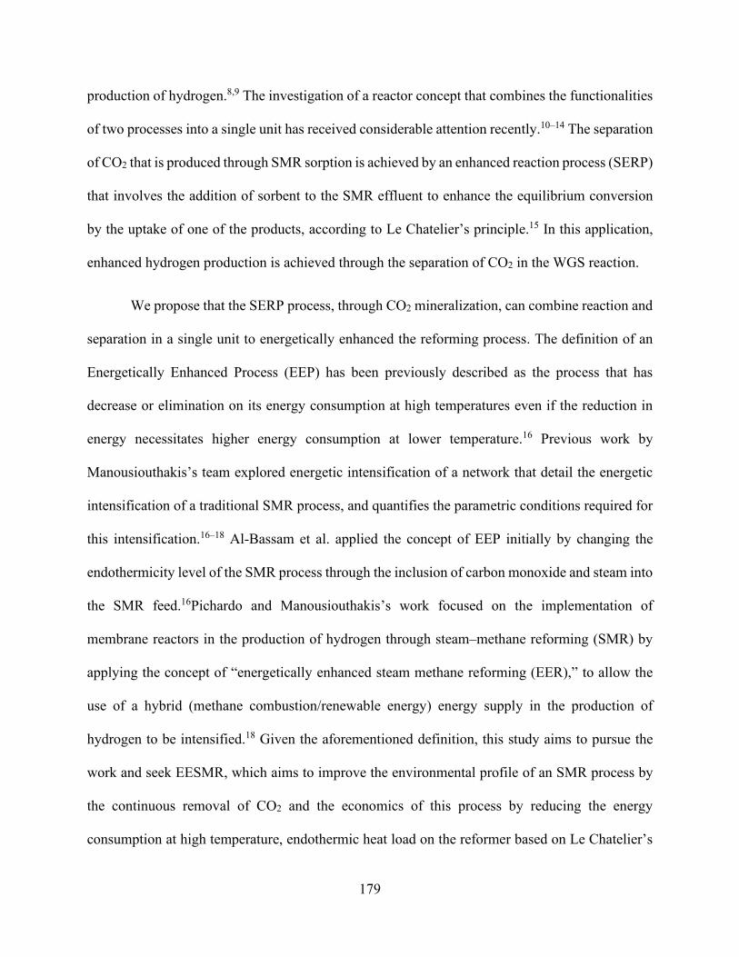
179
production of hydrogen.8,9 The investigation of a reactor concept that combines the functionalities
of two processes into a single unit has received considerable attention recently.10–14 The separation
of CO2 that is produced through SMR sorption is achieved by an enhanced reaction process (SERP)
that involves the addition of sorbent to the SMR effluent to enhance the equilibrium conversion
by the uptake of one of the products, according to Le Chatelier’s principle.15 In this application,
enhanced hydrogen production is achieved through the separation of CO2 in the WGS reaction.
We propose that the SERP process, through CO2 mineralization, can combine reaction and
separation in a single unit to energetically enhanced the reforming process. The definition of an
Energetically Enhanced Process (EEP) has been previously described as the process that has
decrease or elimination on its energy consumption at high temperatures even if the reduction in
energy necessitates higher energy consumption at lower temperature.16 Previous work by
Manousiouthakis’s team explored energetic intensification of a network that detail the energetic
intensification of a traditional SMR process, and quantifies the parametric conditions required for
this intensification.16–18 Al-Bassam et al. applied the concept of EEP initially by changing the
endothermicity level of the SMR process through the inclusion of carbon monoxide and steam into
the SMR feed.16Pichardo and Manousiouthakis’s work focused on the implementation of
membrane reactors in the production of hydrogen through steam–methane reforming (SMR) by
applying the concept of “energetically enhanced steam methane reforming (EER),” to allow the
use of a hybrid (methane combustion/renewable energy) energy supply in the production of
hydrogen to be intensified.18 Given the aforementioned definition, this study aims to pursue the
work and seek EESMR, which aims to improve the environmental profile of an SMR process by
the continuous removal of CO2 and the economics of this process by reducing the energy
consumption at high temperature, endothermic heat load on the reformer based on Le Chatelier’s
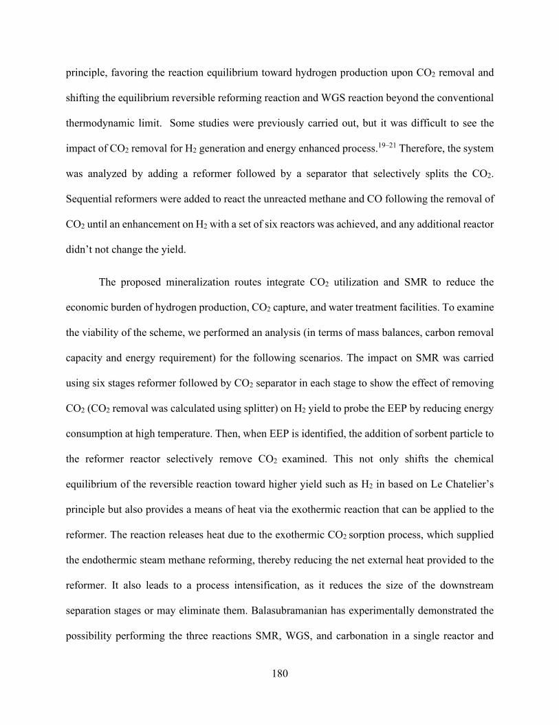
180
principle, favoring the reaction equilibrium toward hydrogen production upon CO2 removal and
shifting the equilibrium reversible reforming reaction and WGS reaction beyond the conventional
thermodynamic limit. Some studies were previously carried out, but it was difficult to see the
impact of CO2 removal for H2 generation and energy enhanced process.19–21 Therefore, the system
was analyzed by adding a reformer followed by a separator that selectively splits the CO2.
Sequential reformers were added to react the unreacted methane and CO following the removal of
CO2 until an enhancement on H2 with a set of six reactors was achieved, and any additional reactor
didn’t not change the yield.
The proposed mineralization routes integrate CO2 utilization and SMR to reduce the
economic burden of hydrogen production, CO2 capture, and water treatment facilities. To examine
the viability of the scheme, we performed an analysis (in terms of mass balances, carbon removal
capacity and energy requirement) for the following scenarios. The impact on SMR was carried
using six stages reformer followed by CO2 separator in each stage to show the effect of removing
CO2 (CO2 removal was calculated using splitter) on H2 yield to probe the EEP by reducing energy
consumption at high temperature. Then, when EEP is identified, the addition of sorbent particle to
the reformer reactor selectively remove CO2 examined. This not only shifts the chemical
equilibrium of the reversible reaction toward higher yield such as H2 in based on Le Chatelier’s
principle but also provides a means of heat via the exothermic reaction that can be applied to the
reformer. The reaction releases heat due to the exothermic CO2 sorption process, which supplied
the endothermic steam methane reforming, thereby reducing the net external heat provided to the
reformer. It also leads to a process intensification, as it reduces the size of the downstream
separation stages or may eliminate them. Balasubramanian has experimentally demonstrated the
possibility performing the three reactions SMR, WGS, and carbonation in a single reactor and

181
produces hydrogen with >95% purity.22 over a range of temperatures, 650 °C was the optimal for
hydrogen generation from methane in a single step reactor with the presence of CaO.
Finally, CO2 removal using aqueous phase absorber is examined using NaOH solution or
ion exchange approach to provide the alkalinity. CO2 mineralization using NaOH and a Ca-or Mg-
rich stream considers solid and liquid sources of Ca and Mg (desalination brines, Ca-rich
groundwater, solid industrial byproducts, and waste). The H+-ion-exchange scenario uses
regenerable materials. This study explored the possibility of reforming methane
thermodynamically with the simulated removal of CO2 through mineralization. The equilibrium
concentrations of different species were calculated by minimizing Gibbs free energy. The thermal
energy requirements of the reforming system were evaluated by performing material and energy
balance. Precipitation was calculated thermodynamically for the CO2 mineralization process using
NaOH and experimentally for the ion-exchange effluent precipitation stream.
Energy consumption in the NaOH process is primarily associated with the addition of
alkalinity that is provided by electrolysis, whereas the ion-exchange process increases alkalinity
or reduces acidity without involving consumable reagents. Ion-exchange processes use novel solid
ion exchangers that are capable of reversibly capturing CO2 from the steam reformer effluent
stream. Ion-exchange materials are commonly used for the removal of heavy metal cations and
hardness (e.g., zeolites, resins, and clays) from wastewater; these materials have also been used
for the treatment of acid mine drainage, which results in slight pH increases after the removal of
metals, implying that pH swing via ion-exchange can be achieved.23
The regeneration energy requirement for CO2 capture using solid ion exchangers is
significantly less than that of dry solid adsorbent and aqueous amine-based processes. The inherent
advantage of the ion-exchange process is that it is simple to operate. Unlike the adsorption process,

182
only ion exchange requires vessels that are able to withstand the ion-exchange process. As with
the adsorption process, the ion-exchange process has a regenerative material that can be reused.
Furthermore, zeolite-based sorbents are low cost and require low regeneration energy. Previous
research has shown that both a forward and reverse H+/Na+ exchange can occur.24–26 The present
process of a precipitated calcium carbonate production approach involves three essential steps
(Figure 6.1): the calcination of high-purity natural limestone to produce lime, the slaking of lime
to produce hydrated lime, and the carbonation of hydrated lime with CO2 in water to precipitate
CaCO3.27,28
Figure 6.1. The conventional process of precipitated calcium carbonate production.29

183
6.3 Materials and Methods
6.3.1 Experimental Solutions
Solutions for forwarding ion-exchange experiments for both batch equilibrium and
dynamic experiments were performed by bubbling CO2 into high-purity water that had been
purified by a Milli-Q system to reach saturation (pCO2 = 1.0 ATM, pH = 4). Additionally, batch
equilibrium experiments were performed using various concentrations of HCl, diluted from 12%
HCl purchased from Sigma-Aldrich. A Thermo Scientific Orion pH electrode was used to measure
initial and final pH values for the ion-exchange experiments. The NaCl (≥99.0%) used for the
regeneration experiments was purchased from Thermo Fisher Scientific. The CaCl2∙2 H2O
(≥99.0%) and MgCl2∙6 H2O (≥98.0%) used for competitive ion-exchange experiments were
purchased from Thermo Fisher Scientific. Cation concentrations in solution were measured by
ICP-OES using an Avio 200 ICP Optical Emission Spectrometer from Perkin Elmer. Solutions for
ICP-OES were diluted in 5% HNO3 (diluted from 70% HNO3 obtained from Sigma-Aldrich).
6.3.2 Characterization of Ion-Exchange Materials
Commercially available zeolites 13X and 4A were obtained in sodium form from Thermo
Fisher Scientific, and the weakly acidic organic ion-exchange resins Lewatit TP 207
(iminodiacetate functional group) and Lewatit TP 260 (aminomethyl phosphonate functional
group) were obtained in sodium form from Sigma-Aldrich.

184
6.3.3 Batch Equilibrium Experiments
Batch equilibrium experiments were performed in CO2-saturated solutions and in HCl
solutions to determine the effect of the counterion in the forward ion-exchange step at 25°C.
Equilibrium exchange capacities (EC) for ion-exchange materials were calculated by the following
equation:
𝐸𝐸𝐶𝐶 = (𝐶𝐶𝑓𝑓−𝐶𝐶0)∙𝐿𝐿𝑊𝑊
(1)
where 𝐶𝐶𝑜𝑜 and 𝐶𝐶𝑜𝑜 are the final and initial sodium concentrations respectively, 𝑉𝑉 is the
solution volume, and 𝑊𝑊 is the mass of solid used for ion-exchange. All experiments were
performed using a solid to-liquid-ratio of 0.05 g/mL.
6.3.4 Thermodynamic Modeling
A model is developed to analyze the effect of sorbent on the syngas composition. A
sequential modular simulation (SMS) approach has been used to simulate the rector. In this
method, the reactor is divided into several stages where each section consists of a reformer and a
carbonation reaction. Thermodynamic analysis of the chemical equilibrium was performed based
on the Gibbs reactor using Aspen Plus. The Gibbs reactor was implemented using the Peng
Robinson equation of state method due to its suitability in handling a system that contains
hydrocarbons, water, air, and combustion gases.30,31 This reactor calculates the reaction product
distribution by the minimization of the Gibbs free energy of each participating species in the

185
reaction system, irrespective of the reaction network. The Gibbs reactor was preferred in the steam
reforming process.32,33
A Gibbs reactor is based on finding the thermodynamic favorability of a system when
Gibbs free energy is at a minimum value, which is achieved when the differential achieves zero
for a given temperature and pressure, determined according to the following equation31,34:
(𝑑𝑑𝐺𝐺𝑇𝑇)𝑇𝑇,𝑎𝑎 = 0
CO2 mineralization was performed using eRNTL as the thermodynamic property method.35
The property method considers Hilgard thermodynamics, CO2 reaction kinetics, and other mass
transfer phenomena associated with system mixture. The model explicitly accounts for the solution
chemistry, which includes dissociations of H2O, NaOH, CaCl2, and CO2, the formation of
bicarbonate, and the precipitation of calcium carbonate.
6.4 Process Description and Results
6.4.1 Steam Methane Reforming (SMR)
In conventional SMR, methane is reacted with steam using a nickel-based catalyst at the
relatively high endothermic reaction temperature of 923–1273 K, and pressure equivalent to 5–40
bar, to produce carbon monoxide and hydrogen. Then, additional carbon monoxide is reacted with
water to produce hydrogen in the WGS reaction.36 Exothermic WGS operates at a temperature of
573–673 K and pressure of 6.9–31 bar through an iron-based catalyst. Typical WGS effluent
consists of a mixture of 71–75% hydrogen, 5–35% CO2, 1–4% CO, and 4–7% CH4 on a dry basis.14
𝐶𝐶𝐻𝐻4 + 𝐻𝐻2𝑂𝑂 ⇌ 𝐶𝐶𝑂𝑂 + 3𝐻𝐻2 (Δ𝐻𝐻2980 = 206.2 kJ/mol) (1)
𝐶𝐶𝑂𝑂 + 𝐻𝐻2𝑂𝑂 ⇌ 𝐶𝐶𝑂𝑂2 + 𝐻𝐻2 (Δ𝐻𝐻2980 = −41.2 kJ/mol) (2)

186
𝐶𝐶𝐻𝐻4 + 2𝐻𝐻2𝑂𝑂 ⇌ 𝐶𝐶𝑂𝑂2 + 4𝐻𝐻2 (Δ𝐻𝐻2980 = 165 kJ/mol) (3)
Optimum reforming conditions were specified by performing sensitivity analysis with
Aspen Plus. The chapter reports the results of the investigation to determine the temperature,
steam-to-methane ratio, and pressure combination values that provide the highest H2 yield at the
lowest energy possible. In this process, steam had a substantial effect on the H2 rate in production,
increasing the ratio of steam-to-methane from 1:1 to 1:10, and increased the production of
hydrogen by nearly 80% (Figure 6.2). This is consistent with the results obtained by Hegarty et
al.31,37 However, increasing the steam ratio also caused a substantial decrease in CO2 conversion.
When the ratio of steam was increased, CH4 reacted with H2O instead of CO2. Hydrogen increased
steadily with the increase in the steam-to-methane ratio in parallel with the CO2 ratio. This resulted
in a WGS reaction that shifted the equilibrium to the right due to the H2O surplus. Methane and
CO were not favored as the ratio of steam to methane increased. The higher the steam-to-methane
ratio was, the higher the conversion was. Energy consumption also increased with increasing the
steam-to-methane ratio. Thus, the optimum thermodynamic yield was achieved at a steam-to-
methane ratio of 3:1.
Methane and CO2 dominated production at low temperatures. As the temperature increased
at temperatures higher than 950 K, the increment in temperature did not contribute to hydrogen
production any further. In addition to temperature and steam-to-methane ratio, pressure was also
a critical parameter that had an effect on the equilibrium distribution of the product (Figure 6.3).
The calculation was performed using a temperature of 950 K and a steam-to-methane ratio of 3:1.
The temperature and steam-to-methane ratio were selected to achieve the maximum hydrogen
yield and low levels of carbon monoxide. The H2 yield was significantly suppressed within the
temperature range of 200–950 K. However, the change in pressure at a higher pressure than 950
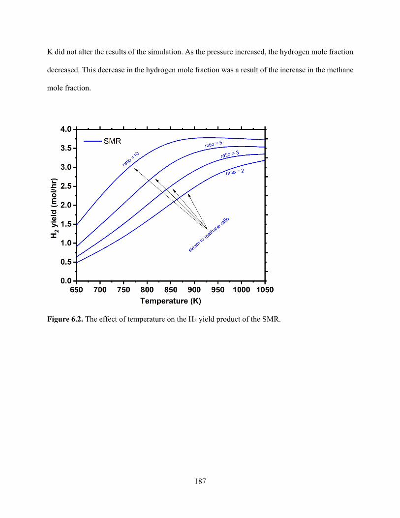
187
K did not alter the results of the simulation. As the pressure increased, the hydrogen mole fraction
decreased. This decrease in the hydrogen mole fraction was a result of the increase in the methane
mole fraction.
Figure 6.2. The effect of temperature on the H2 yield product of the SMR.

188
Figure 6.3. The effect of pressure on the SMR product proportions of H2, CH4, CO and H2O.
6.4.2 Effect of Removing CO2 from SMR outlet
The Sorption-enhanced steam reforming (SESR) was briefly described in the introduction
section. The process flow diagram developed in the simulation SESR is shown in Figure 6.4. SESR
represents a promising method for producing H2 with high purity.38 In a conventional SMR, a
purification step is carried out by pressure swing adsorption (PSA) for the WGS effluent to produce
pure hydrogen. The PSA feed is typically operates at a temperature of 293–313 K and at a pressure
of 6.9–31 bar. Typical H2 that is recovered by the PSA process (H2 in product/H2 in feed) is
approximately 70–85% pure. The remaining waste gas impurities (H2O, CO2, CO, CH4, and N2)
remain.
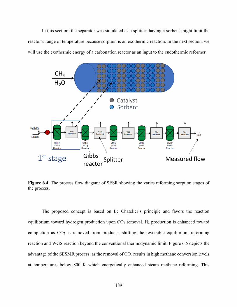
189
In this section, the separator was simulated as a splitter; having a sorbent might limit the
reactor’s range of temperature because sorption is an exothermic reaction. In the next section, we
will use the exothermic energy of a carbonation reactor as an input to the endothermic reformer.
Figure 6.4. The process flow diagamr of SESR showing the varies reforming sorption stages of the process.
The proposed concept is based on Le Chatelier’s principle and favors the reaction
equilibrium toward hydrogen production upon CO2 removal. H2 production is enhanced toward
completion as CO2 is removed from products, shifting the reversible equilibrium reforming
reaction and WGS reaction beyond the conventional thermodynamic limit. Figure 6.5 depicts the
advantage of the SESMR process, as the removal of CO2 results in high methane conversion levels
at temperatures below 800 K which energetically enhanced steam methane reforming. This

190
superiority of SESMR at lower low temperatures over SMR can be observed and related to the in-
situ capture of the produced CO2.
Increasing the steam-to-methane ratio increased the equilibrium of the reforming and WGS
reactions to the product side, which resulted in high methane conversion, H2 yield and CO2
production. Increasing the equilibrium of the WGS increased CO2 production, thus favoring the
CO2 mineralization reaction, and producing H2 with high purity at a lower operating temperature
than that of SMR (Figure 6.5). Steam to methane ratio follows Le Chatelier”'s principle as well,
whereby an increase in the water concentration moves the equilibrium toward higher water
conversion, thus producing higher H2 yield. The effect of the ratio levels off at higher values (above
steam-to-methane ratio: 4 and 700–1200 K).39,40
Figure 6.5. Effect of temperature on the H2 yield product of the SESR

191
6.4.3 The Use of Exothermic Carbonation Energy for Reforming
The addition of a sorbent particle to the reformer reactor selectively removes CO2. This
shifts the chemical equilibrium of the reversible reaction toward a higher yield such as H2 in the
previous section based on Le Chatelier’s principle and provides a means of heat via the exothermic
reaction that can be applied to the reformer. Table 6.2 depicts the advantage of combining steam
reforming within in situ CO2 capture from an energy viewpoint. The addition of sorbents, such as
CaO, could be favorable to the SMR process for several reasons such as:41
• Reforming reactions can be enhanced energetically operating at a reduced energy
consumption at higher temperatures, as seen in the previous section.
• Heat released from the exothermic carbonation reaction can supply most of the energy
needed for the endothermic reforming reactions, as discussed in this section.
• It captures and stabilizes CO2 in the form of solid carbonates, which will be discussed in
the following section.
In this section, the overall inlet (1 mol/hr of CH4 and 3 mol/hr of H2O) and the overall
outlet (3.21 mol/hr of H2 and 0.27 mol/hr of CO) are based on 80% overall conversion of CH4.
The process is displayed below (Figure 6.6), with a sequence of six reforming reactors followed
by carbonation reactors in each stage. All the reactors were modeled as a conversion reactor with
the feed 1 mole of CH4 and 3 H2O, and each reformer with the WGS reactor is followed by a
carbonation reactor as follows:
𝐶𝐶𝑂𝑂2 + 𝐶𝐶𝑎𝑎𝑂𝑂 ⇌ 𝐶𝐶𝑎𝑎𝐶𝐶𝑂𝑂3 (4)
In each carbonation reactor, 0.1 mol of CaO was added. For each of the reactions in the
reformer (Eq. 1, 2 and 3), 10% conversion was assumed, meaning that CH4 was 10% converted in

192
Eq. 1 and 3 and 10% CO conversion in Eq. 2. This maintains the 0.1 mol/hr of CO2 after each
reformer to be consumed by each 0.1 mol CaO that was added to each carbonation reactor. From
Table 6.1, we can see a summary of the flow rate over the varies stages of the flowsheet. 1 mol/h
CH4 enters the reactor with 3 mol/hr H2O, following the first reformer stage, 0.1 mol/h. 0.70 mol/h
and 0.1 mol/h of CO2, CO and H2 were generated, respectively through exothermic reaction of
reformer -5.39 kJ/s (the first reformer was the only reformer which operated exothermally
probably due to the higher contribution of WGS reaction compare to reforming reaction, following
the first stage reformer, the rest of reformers operated endothermically) (Table 6.2). The 0.1 mol/hr
CO2 produced from the first reformer reacted with 0.1 mol/h CaO that was added to the first
carbonation reactor generating an exothermic heat equivalent to -4.71 kJ/s. In overall, the presence
of CaO sorbent in SMR lowers the CO2 concentration (0.1 instead of 19% in SMR) and produces
a richer hydrogen stream (89.4 instead of 70% in SMR). The heat duty of each reactor is
exothermic reaction heat, as fed to any endothermic reactor, which was reformer-operated
isothermally at 550°C with 38.32 kJ/s heater requirement. In this process, the heat released by
exothermic carbonation reaction, which is equivalent to 29.48 kJ/s, was able to supply most of the
heat required by the endothermic reforming reactions, which in this case is 39.29 kJ/s.
Figure 6.6. Aspen Plus flowsheet depicting each stage reactor “REF” represents the reformer and six reactors
Table 6.1. Summary table of all the reactor stages flows streams.

193
Feed mol/hr
1st Stage mol/hr
2nd Stage mol/hr
3rd Stage mol/hr
4th Stage mol/hr
5th Stage mol/hr
6th Stage mol/hr
Product mol/hr
Mole Flows 4.00 4.40 4.78 5.10 5.33 5.56 5.74 5.74
CaO 0.00 0.00 0.00 0.00 0.00 0.00 0.00 0.00
CO2 0.00 0.10 0.11 0.11 0.10 0.10 0.10 0.00
CaCO3 0.00 0.00 0.10 0.20 0.30 0.40 0.50 0.60
CH4 1.00 0.80 0.61 0.45 0.33 0.22 0.13 0.13
H2O 3.00 2.70 2.40 2.14 1.93 1.72 1.53 1.53
CO 0.00 0.10 0.18 0.24 0.27 0.28 0.27 0.27
H2 0.00 0.70 1.38 1.96 2.40 2.84 3.21 3.21
Table 6.2. Energy streams information for reforming and carbonation reactors of each stage.
Reactor 1st reform 1st carb 2nd reform 2nd carb 3rd reform 3rd carb
name on PFD REF1 CARB1 REF2 CARB2 REF3 CARB3
Energy (kJ/s) -5.39 -4.71 10.17 -4.95 8.22 -4.95
Reactor 4th reform 4th carb 5th reform 5h carb 6th reform 6th carb
name on PFD REF4 CARB4 REF5 CARB5 REF6 CARB6
Energy (kJ/s) 5.93 -4.95 5.57 -4.95 4.10 -4.95
6.4.4 Sorption-Enhanced Steam Reforming by NaOH
In this case, the reactor contained both the catalyst needed for the reforming process and
an additional step that uses NaOH for the removal of CO2 (Figure 6.7). The CO2 capture and overall
SERP reaction are formulated as follows:
𝐶𝐶𝑂𝑂2 + 𝐻𝐻2𝑂𝑂 ⇌ 𝐻𝐻2𝐶𝐶𝑂𝑂3 (5)

194
𝐻𝐻2𝐶𝐶𝑂𝑂3 ⇌ 𝐻𝐻𝐶𝐶𝑂𝑂3− + 𝐻𝐻+ (6)
𝐻𝐻𝐶𝐶𝑂𝑂3− +⇌ 𝐶𝐶𝑂𝑂32− + 𝐻𝐻+ (7)
𝐶𝐶𝑎𝑎2+ + 𝐶𝐶𝑂𝑂32− ⇌ 𝐶𝐶𝑎𝑎𝐶𝐶𝑂𝑂3 (8)
Figure 6.8 illustrates the calcium carbonation precipitation, plotting the calcium
carbonation precipitation as a function of NaOH addition. The precipitation is promoted at high
solution pH. The figure demonstrates that at the NaOH:CO2 flow rate ratio of 2:1, complete
purification of the product stream was achieved. Further increases in the NaOH-to-CO2 ratio over
2:1 had no effect on the amount of CO2 removed but had a negative impact on the overall energy
because the use of more NaOH requires more energy through the electrolysis of brine solution.
Therefore, the ratio of NaOH should be carefully chosen to achieve a resealable operation mode.
Minimum thermodynamic energy needed for electrolysis is in the range of 0.65 - 0.81 KWh/ kg
of NaOH, whereas that of the current Chlor-alkali process is approximately 2.1 - 2.2 kWh/kg of
NaOH42.
A ratio of more than 2:1 for NaOH to CO2 did not have a significant effect. Thus, the
optimum ratio of 2:1 was chosen for the addition of NaOH to the various reformer inlet steam-to-
methane ratios.
Figure 6.8 illustrates the composition of the effluent stream as a function of reactor
temperature, where increasing the removal fraction of CO2 increases the production of H2. This
route provides more stable storage for CO2 in the form of mineral carbonates compared to CO2
capture and storage. However, it uses higher energy per tons of CO2 utilized. Two moles of sodium
carbonate are required to precipitate 1 mole of carbon dioxide. Therefore, approximately 3.78
MWh is required for each ton of CO2 utilized using the Chlor-alkali process.

195
Figure 6.7. Process diagram for the proposed process of the carbonation of produced water using NaOH absorption to continuously remove CO2. Three reactors, namely (1) a reformer and WGS reactor, (2) an absorber, and (3) a precipitation reactor, are shown.
Figure 6.8. Calcium carbonation precipitation as a function of NaOH addition.

196
6.4.5 Ion-Exchange-Enhanced Steam Reformer
The ion-exchange-enhanced steam reformer process involves the use of regenerable solids
that remove H+ from aqueous solution during carbonation (Figure 6.9). This induces an increase
in alkalinity, which is favorable for calcite precipitation. This process involves the following steps.
(1) CO2 from a steam reformer effluent stream (~7% CO2) is bubbled into an ion-exchanger
containing water and an ion-exchanger solid. Water equilibrates with the flue gas stream and
dissolves CO2 acidifies the aqueous solution then forms H2CO3. As the H+ concentration in the
water increases, those ions exchange with monovalent ions contained within the ion-exchanger
solid (e.g., Na+), which prevents the pH from further decreasing. Essentially, this step captures
CO2 from steam reformer effluent passing through the ion-exchanger, inducing the reaction
equilibrium toward hydrogen production upon CO2 removal, and converting dissolved carbonic
acid into NaHCO3. Once the ion-exchanger solid becomes saturated with H+, it is replaced with
fresh solid and prepared for regeneration.
(2) In the next step, the NaHCO3 solution exiting the ion-exchanger is mixed with Ca-rich
produced water. This produces PCC that can be separated from the solution by filtering or
gravitational settling. The residual solution then passes through an RO module to recycle water for
reuse in step 1. As the produced water has high salinity, the RO module also produces a retentate
solution with concentrated Na+.
(3) In the final step, the retentate from the RO module is introduced to the H+-saturated
ion-exchanger solid in a regeneration reactor. The high Na+ concentration in the retentate promotes
a reverse ion-exchange reaction, in which Na+ replaces the H+ in the solid, thus regenerating the
solid for reuse. In full-scale implementations, liquid discharge from the final step is fed into the
produced water treatment process for concentration and salt crystallization.

197
The H+–Na+ ion-exchange was conducted by adding the solids (0–1.0 kg/kg) to a saturated
CO2 water (pH 4, pCO2 = 1 ATM; Figure 6.10 b). For all types, an increase in pH coupled was
observed, indicating the possibility of the ion-exchange process, and illustrating that significant
basicity can be generated. The Lewatit TP 207(Na) and 260 were superior to zeolite in terms of
ion-exchange and increased the solution alkalinity from 4 to approximately 10 pH. In
performance, they were followed by weakly acidic ion exchangers such as zeolite 13X and 4A and
then strongly acidic ion exchangers such as Amberlite 200C(Na), Amberlite IR120(Na), Diaion
SK112(Na) and Lewatit M+SP 112(Na). The strong acid resin was highly dissociated, and thus,
the cation was available for exchange over the entire pH range and a considerable excess of acid
was needed to convert the sodium form to the hydrogen form. The weak acid cation resin was
functionalized with carboxyl groups.
Figure 6.10 (a) shows the EC of the ion-exchange materials in various concentrations of
HCl solutions and CO2-saturated solutions to indicate the effect of the initial concentration on
exchange capacity. In this case, the total number of cations in the systems was constant, using 1 g
of an ion-exchanger. Changing the concentration of CO2 from 15% to 100% resulted in lower
equilibrium concentrations and, thus, lower EC. As the water equilibrated with the flue gas stream,
dissolved CO2 acidified the water by forming H2CO3. As the H+ concentration in the water
increased, ions exchanged with monovalent ions contained within the ion-exchanger solid (Na+),
which prevented a further decrease of pH. Thus, the maximum exchange capacity was achieved at
the initial CO2 concentration of 14% with 0.6 mmol/g. This followed the same trend observed with
Na+/H+ exchange in HCl solution. Maximum exchange capacity with organic exchange resin was
achieved at 1 M HCl (~3 mmol/g Na released), whereby high amount of Na was released from
zeolites due to dissolution.

198
Figure 6.9. Process diagram for the proposed process of the carbonation of produced water using ion-exchange. Three reactors, namely (1) a reformer and WGS reactor, (2) an ion-exchange reactor, and (3) a precipitation reactor, are shown.
Figure 6.10. Equilibrium isotherms for CO2 solutions developed using saturated CO2 (pH 3.9, 100% CO2), pH 4.5, and pH 5.3.
Ion-exchange reaction kinetics were studied at different temperatures to determine their
effect on exchange rates and EC. Increasing temperature increased the reaction rate constant for
all materials, due to the increased mobility of ions (Figure 6.11). Increasing temperature increased
(a) (b
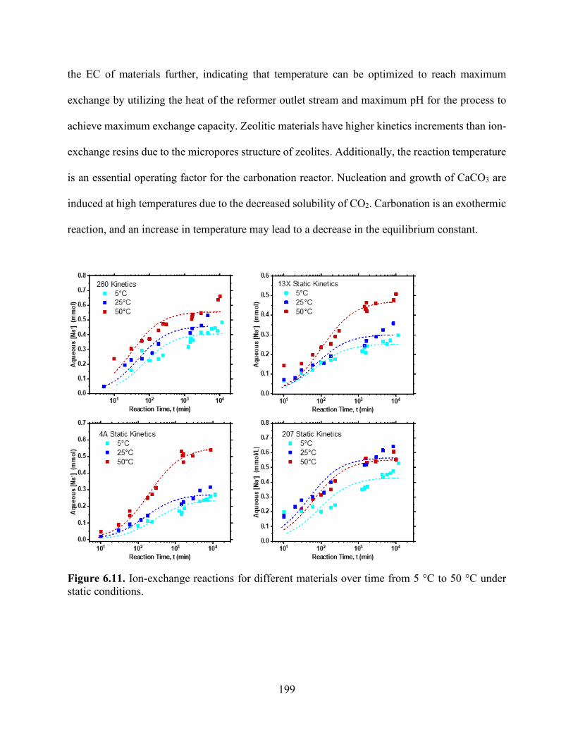
199
the EC of materials further, indicating that temperature can be optimized to reach maximum
exchange by utilizing the heat of the reformer outlet stream and maximum pH for the process to
achieve maximum exchange capacity. Zeolitic materials have higher kinetics increments than ion-
exchange resins due to the micropores structure of zeolites. Additionally, the reaction temperature
is an essential operating factor for the carbonation reactor. Nucleation and growth of CaCO3 are
induced at high temperatures due to the decreased solubility of CO2. Carbonation is an exothermic
reaction, and an increase in temperature may lead to a decrease in the equilibrium constant.
Figure 6.11. Ion-exchange reactions for different materials over time from 5 °C to 50 °C under static conditions.

200
6.5 Discussion
The production of hydrogen and other species at different temperatures and pressures was
analyzed on the basis of thermodynamic analysis. Our simulation showed that the process was able
to produce a pure H2 stream after the mineralization step. The effect of temperature on methane
conversion and hydrogen purity was illustrated for the two investigated processes. In conventional
steam reforming, increased the temperature increased the conversion of methane due to the
endothermic reaction, which is induced at high temperatures. The presence of CO2 sorbent led to
further methane conversion and changed the equilibrium shift of the reaction. The effect of
increasing steam increased the concentration of hydrogen in the outlet stream. In this case, H2
production and methane conversion were enhanced due to steam and CO2 conversion, which led
to the removal of CO2 and the production of high-purity hydrogen. At a temperature of less than
650 K, CO2 capture efficiency was above 90%. However, as the temperature increased further,
CO2 capture decreased due to the decomposition of CaCO3. Thus, at high temperatures, the
enhanced steam reforming process degenerated into a conventional steam reforming process.
Therefore, the optimal operating condition for SESR is between 550 and 650 K. The highest
quantity of hydrogen was achieved with excess steam at all temperatures.
In the ion-exchange process, weakly acidic function groups exhibited higher ion-exchange
capacities than did zeolitic materials; this may be a result of the availability of exchange sites and
the affinity of proton. Weak acid cation resin exhibits a higher affinity for hydrogen ions than
strong acid cation due to the presence of the carboxylic functional group in their backbone
structure. The ion-exchange potential of hydrogen ions is dependent on the strength of the acid
functional group and hydrogen; stronger acid entails lower ion-exchange potential. This
demonstrated that strong acidic resins might not be suitable candidates for ion-exchange, as their

201
ability to attract protons is much lower than that of sodium. Strongly acidic resin exhibited lower
exchange performance than did the weakly acidic resin. Weakly to moderate acidic ion exchangers
such as zeolite (13X and 4A) had less hydrogen affinity than weekly acidic resin but were able to
convert dissolved carbonic acid into NaHCO3. Zeolite Na-X has a cation exchange capacity of 0.6
mmol g-1, a lower exchange capacity than Na-A, and does not proceed to a full exchange.
In both processes, H2 yield was energetically enhanced the removal of CO2. It can be
observed that due to the intensification effect, CH4 conversion was promoted to a higher value
because of Le Chatelier’s principle. To probe the effect of Le Chatelier’s principle to improve the
process more, we simulated the effect of continuous removal of H2 from the outlet stream which
can be achieved by coupling the SESR process with a selective membrane that can selectively
remove H2 (Figure 6.12) 43. In Aspen Plus this model is a combination of component splitters. The
hydrogen-rich gas was assumed to contain 98% hydrogen and 2% methane, carbon monoxide and
water combined.44 The hydrogen-rich gas was then fed to PSA unit that recovers hydrogen with a
purity of 99.99%. The PSA was modeled as component splitter block in Aspen Plus.45,46
Results showed significant improvement in the H2 product yield with even lower
temperatures than that achieved in the SESR process (Figure 6.13).

202
Figure 6. 12. Process Flow diagram showing the effect of temperature on the H2 yield product of the SESR with the continuous removal of H2 from outlet
Figure 6.13. The effect of temperature on the H2 yield product of the SESR with the continuous removal of H2 from outlet.
6.6 Conclusion
In this study, SMR was enhanced using CO2 mineralization. Thermodynamic calculations
were made by using the method of Gibbs free energy minimization to determine the optimum
conditions of temperature, steam-to-methane ratio, and pressure to produce hydrogen with high
yields. The product composition at thermodynamic equilibrium was determined by minimizing the
total Gibbs reaction scheme free energy at a temperature-pressure-feed composition. The results
demonstrated that for all models, hydrogen yield is induced at high temperatures and high steam-

203
to-methane ratios. The analysis suggests that the most favorable temperature is between 800 and
950 K. Increasing the steam-to-methane ratio and temperature resulted in higher hydrogen yield,
but after a certain value, the addition becomes uneconomical, due to the high energy used.
Another finding is that pressure has a negative effect on the hydrogen production yield.
The combined process of reaction and separation enhanced the disappearance of carbon monoxide
due to the formation of carbon dioxide, which was enhanced by the simultaneous CO2
mineralization. Due to the more favorable position of the equilibrium of the steam reforming
reaction, product formation was accelerated to a greater extent. Through use of the model, the
contribution of equilibrium conversion and the sorption enhancement were quantified.
A model analysis was performed to probe the effect of producing high-purity H2 with
minimum CO concentration. Different types of ion-exchange materials were screened to examine
their ability to increase the pH of the acidic solutions containing HCl and dissolve CO2. These ion-
exchange materials were screened using CO2-rich feeds (CO2-saturated water at atmospheric
pressure has a pH of 4); ion-exchange in this system resulted in both an increase in pH and a
change in the speciation of carbon in a solution to carbonate ions (which can be used for
mineralization). These results indicate that both zeolite and organic exchange resins are far from
their ideal EC in a CO2-saturated solution but are able to exchange enough protons to induce a pH
swing to the desired pH regions for CO2 mineralization. An increase in temperatures yields an
increase in EC and kinetics for all materials, implying that temperature may be optimized to
achieve ideal capacity.

204
6.7 References
1. Broda, M.; Manovic, V.; Imtiaz, Q.; Kierzkowska, A. M.; Anthony, E. J.; Müller, C. R. High-
Purity Hydrogen via the Sorption-Enhanced Steam Methane Reforming Reaction over a
Synthetic CaO-Based Sorbent and a Ni Catalyst. Environ. Sci. Technol. 2013, 47 (11), 6007–
6014. https://doi.org/10.1021/es305113p.
2. Ebneyamini, A.; Grace, J. R.; Lim, C. J.; Ellis, N.; Elnashaie, S. S. E. H. Simulation of
Limestone Calcination for Calcium Looping: Potential for Autothermal and Hydrogen-
Producing Sorbent Regeneration. Ind. Eng. Chem. Res. 2019, 58 (20), 8636–8655.
https://doi.org/10.1021/acs.iecr.9b00668.
3. Kalamaras, C. M.; Efstathiou, A. M. Hydrogen Production Technologies: Current State and
Future Developments. Conf. Pap. Energy 2013, 2013, 1–9.
https://doi.org/10.1155/2013/690627.
4. Iulianelli, A.; Liguori, S.; Wilcox, J.; Basile, A. Advances on Methane Steam Reforming to
Produce Hydrogen through Membrane Reactors Technology: A Review. Catal. Rev. - Sci. Eng.
2016, 58 (1), 1–35. https://doi.org/10.1080/01614940.2015.1099882.
5. Balat, M.; Balat, M. Political, Economic and Environmental Impacts of Biomass-Based
Hydrogen. Int. J. Hydrogen Energy 2009, 34 (9), 3589–3603.
https://doi.org/10.1016/j.ijhydene.2009.02.067.
6. Onozaki, M.; Watanabe, K.; Hashimoto, T.; Saegusa, H.; Katayama, Y. Hydrogen Production
by the Partial Oxidation and Steam Reforming of Tar from Hot Coke Oven Gas. Fuel 2006,
85 (2), 143–149. https://doi.org/10.1016/j.fuel.2005.02.028.
7. Muradov, N. Z.; Veziroǧlu, T. N. From Hydrocarbon to Hydrogen-Carbon to Hydrogen
Economy. Int. J. Hydrogen Energy 2005, 30 (3), 225–237.

205
https://doi.org/10.1016/j.ijhydene.2004.03.033.
8. Chanburanasiri, N.; Ribeiro, A. M.; Rodrigues, A. E.; Arpornwichanop, A.; Laosiripojana, N.;
Praserthdam, P.; Assabumrungrat, S. Hydrogen Production via Sorption Enhanced Steam
Methane Reforming Process Using Ni/CaO Multifunctional Catalyst. Ind. Eng. Chem. Res.
2011, 50 (24), 13662–13671. https://doi.org/10.1021/ie201226j.
9. Ortiz, A. L.; Harrison, D. P. Hydrogen Production Using Sorption-Enhanced Reaction. Ind.
Eng. Chem. Res. 2001, 40 (23), 5102–5109. https://doi.org/10.1021/ie001009c.
10. Gilles, E. D.; Lauschke, G.; Kienle, A.; Storz, M. Some Aspects of Integrated Process
Operation. In Annual Reviews in Control; Elsevier, 1996; Vol. 20, pp 9–22.
https://doi.org/10.1016/S1367-5788(97)00002-3.
11. Westerterp, K. R. Multifunctional Reactors. Chem. Eng. Sci. 1992, 47 (9–11), 2195–2206.
https://doi.org/10.1016/0009-2509(92)87035-O.
12. Wang, Y. N.; Rodrigues, A. E. Hydrogen Production from Steam Methane Reforming Coupled
with in Situ CO2 Capture: Conceptual Parametric Study. Fuel 2005, 84 (14–15), 1778–1789.
https://doi.org/10.1016/j.fuel.2005.04.005.
13. Agar, D. W. Multifunctional Reactors: Old Preconceptions and New Dimensions. Chem. Eng.
Sci. 1999, 54 (10), 1299–1305. https://doi.org/10.1016/S0009-2509(99)00040-8.
14. Sircar, S.; Waldron, W. E.; Rao, M. B.; Anand, M. Hydrogen Production by Hybrid SMR-
PSA-SSF Membrane System. Sep. Purif. Technol. 1999, 17 (1), 11–20.
https://doi.org/10.1016/S1383-5866(99)00021-0.
15. Le Chatelier, H. Sur La Dilatation Des Metaux Aux Temperatures Elevees. Cornpt. rend 1889,
108, 1096.
16. Al-Bassam, A. M.; Conner, J. A.; Manousiouthakis, V. I. Natural-Gas-Derived Hydrogen in

206
the Presence of Carbon Fuel Taxes and Concentrated Solar Power. ACS Sustain. Chem. Eng.
2018, 6 (3), 3029–3038. https://doi.org/10.1021/acssuschemeng.7b02745.
17. Pichardo, P.; Manousiouthakis, V. I. Infinite DimEnsionAl State-Space as a Systematic
Process Intensification Tool: Energetic Intensification of Hydrogen Production. Chem. Eng.
Res. Des. 2017, 120, 372–395. https://doi.org/10.1016/j.cherd.2017.01.026.
18. Pichardo, P. A.; Manousiouthakis, V. I. Intensified Energetically Enhanced Steam Methane
Reforming through the Use of Membrane Reactors. AIChE J. 2020, 66 (2), e16827.
https://doi.org/10.1002/aic.16827.
19. Tzanetis, K. F.; Martavaltzi, C. S.; Lemonidou, A. A. Comparative Exergy Analysis of
Sorption Enhanced and Conventional Methane Steam Reforming. Int. J. Hydrogen Energy
2012, 37 (21), 16308–16320. https://doi.org/https://doi.org/10.1016/j.ijhydene.2012.02.191.
20. Romano, M. C.; Cassotti, E. N.; Chiesa, P.; Meyer, J.; Mastin, J. Application of the Sorption
Enhanced-Steam Reforming Process in Combined Cycle-Based Power Plants. Energy
Procedia 2011, 4, 1125–1132. https://doi.org/https://doi.org/10.1016/j.egypro.2011.01.164.
21. Zhu, L.; Fan, J. Thermodynamic Analysis of H2 Production from CaO Sorption-Enhanced
Methane Steam Reforming Thermally Coupled with Chemical Looping Combustion as a
Novel Technology. Int. J. Energy Res. 2015, 39 (3), 356–369. https://doi.org/10.1002/er.3248.
22. Balasubramanian, B.; Ortiz, A. L.; Kaytakoglu, S.; Harrison, D. P. Hydrogen from Methane in
a Single-Step Process. Chem. Eng. Sci. 1999, 54 (15–16), 3543–3552.
23. Fu, F.; Wang, Q. Removal of Heavy Metal Ions from Wastewaters: A Review. J. Environ.
Manage. 2011, 92 (3), 407–418.
https://doi.org/https://doi.org/10.1016/j.jenvman.2010.11.011.
24. Klein, A. R.; Baldwin, D. S.; Singh, B.; Silvester, E. J. Salinity-Induced Acidification in a

207
Wetland Sediment through the Displacement of Clay-Bound Iron(II). Environ. Chem. 2010, 7
(5), 413–421.
25. Avena, M. J.; De Pauli, C. P. Proton Adsorption and Electrokinetics of an Argentinean
Montmorillonite. J. Colloid Interface Sci. 1998, 202 (1), 195–204.
https://doi.org/10.1006/jcis.1998.5402.
26. Robin, V.; Tertre, E.; Beaufort, D.; Regnault, O.; Sardini, P.; Descostes, M. Ion Exchange
Reactions of Major Inorganic Cations (H+, Na+, Ca2+, Mg2+ and K+) on Beidellite:
Experimental Results and New Thermodynamic Database. Toward a Better Prediction of
Contaminant Mobility In. Appl. Geochemistry 2015, 59 (December), 74–84.
https://doi.org/10.1016/j.apgeochem.2015.03.016.
27. Teir, S.; Eloneva, S.; Zevenhoven, R. Production of Precipitated Calcium Carbonate from
Calcium Silicates and Carbon Dioxide. Energy Convers. Manag. 2005, 46 (18–19), 2954–
2979. https://doi.org/10.1016/j.enconman.2005.02.009.
28. Said, A.; Mattila, H. P.; Järvinen, M.; Zevenhoven, R. Production of Precipitated Calcium
Carbonate (PCC) from Steelmaking Slag for Fixation of CO2. Appl. Energy 2013, 112, 765–
771. https://doi.org/10.1016/j.apenergy.2012.12.042.
29. Nduagu, E.; Björklöf, T.; Fagerlund, J.; Wärnå, J.; Geerlings, H.; Zevenhoven, R. Production
of Magnesium Hydroxide from Magnesium Silicate for the Purpose of CO2 Mineralisation–
Part 1: Application to Finnish Serpentinite. Miner. Eng. 2012, 30, 75–86.
30. Peng, D. Y.; Robinson, D. B. A New Two Parameters Equation of State. Ind. Eng. Chem.
Fundam 1976, 15, 59–64.
31. Özkara-Aydnolu, Ş. Thermodynamic Equilibrium Analysis of Combined Carbon Dioxide
Reforming with Steam Reforming of Methane to Synthesis Gas. Int. J. Hydrogen Energy 2010,
208
35 (23), 12821–12828. https://doi.org/10.1016/j.ijhydene.2010.08.134.
32. Belova, A. A. G.; Yegulalp, T. M.; Yee, C. T. Feasibility Study of In Situ CO2 Capture on an
Integrated Catalytic CO2 Sorbent for Hydrogen Production from Methane. Energy Procedia
2009, 1 (1), 749–755. https://doi.org/10.1016/j.egypro.2009.01.099.
33. Vagia, E. C.; Lemonidou, A. A. Thermodynamic Analysis of Hydrogen Production via Steam
Reforming of Selected Components of Aqueous Bio-Oil Fraction. Int. J. Hydrogen Energy
2007, 32 (2), 212–223. https://doi.org/10.1016/j.ijhydene.2006.08.021.
34. Aktaş, S.; Karakaya, M.; Avci, A. K. Thermodynamic Analysis of Steam Assisted Conversions
of Bio-Oil Components to Synthesis Gas. Int. J. Hydrogen Energy 2009, 34 (4), 1752–1759.
https://doi.org/10.1016/j.ijhydene.2008.12.019.
35. Chen, C.-C.; Song, Y. Generalized Electrolyte-NRTL Model for Mixed-Solvent Electrolyte
Systems. AIChE J. 2004, 50 (8), 1928–1941. https://doi.org/10.1002/aic.10151.
36. Ha-Duong, M.; Grubb, M. J.; Hourcade, J. C. Influence of Socioeconomic Inertia and
Uncertainty on Optimal CO2- Emission Abatement. Nature 1997, 390 (6657), 270–273.
https://doi.org/10.1038/36825.
37. Hegarty, M. E. S.; O’Connor, A. M.; Ross, J. R. H. Syngas Production from Natural Gas Using
ZrO2-Supported Metals. Catal. Today 1998, 42 (3), 225–232. https://doi.org/10.1016/S0920-
5861(98)00096-0.
38. Lysikov, A. I.; Trukhan, S. N.; Okunev, A. G. Sorption Enhanced Hydrocarbons Reforming
for Fuel Cell Powered Generators. Int. J. Hydrogen Energy 2008, 33 (12), 3061–3066.
https://doi.org/https://doi.org/10.1016/j.ijhydene.2008.03.041.
39. Antzara, A.; Heracleous, E.; Bukur, D. B.; Lemonidou, A. A. Thermodynamic Analysis of
Hydrogen Production via Chemical Looping Steam Methane Reforming Coupled with in Situ

209
CO2 Capture. Int. J. Greenh. Gas Control 2015, 32, 115–128.
https://doi.org/https://doi.org/10.1016/j.ijggc.2014.11.010.
40. Antzara, A.; Heracleous, E.; Bukur, D. B.; Lemonidou, A. A. Thermodynamic Analysis of
Hydrogen Production via Chemical Looping Steam Methane Reforming Coupled with in Situ
CO2 Capture. Energy Procedia 2014, 63, 6576–6589.
https://doi.org/https://doi.org/10.1016/j.egypro.2014.11.694.
41. Cheng, Y.; Wei, F.; Jin, Y. Multiphase Reactor Engineering for Clean and Low-Carbon
Energy Applications; Wiley, 2017. https://doi.org/10.1002/9781119251101.
42. Thiel, G. P.; Kumar, A.; Gómez-González, A.; Lienhard, J. H. Utilization of Desalination Brine
for Sodium Hydroxide Production: Technologies, Engineering Principles, Recovery Limits,
and Future Directions. ACS Sustain. Chem. Eng. 2017, 5 (12), 11147–11162.
https://doi.org/10.1021/acssuschemeng.7b02276.
43. Ockwig, N. W.; Nenoff, T. M. Membranes for Hydrogen Separation. Chem. Rev. 2007, 107
(10), 4078–4110. https://doi.org/10.1021/cr0501792.
44. Gabriel, K. J.; Linke, P.; Jiménez-Gutiérrez, A.; Martínez, D. Y.; Noureldin, M.; El-Halwagi,
M. M. Targeting of the Water-Energy Nexus in Gas-to-Liquid Processes: A Comparison of
Syngas Technologies. Ind. Eng. Chem. Res. 2014, 53 (17), 7087–7102.
https://doi.org/10.1021/ie4042998.
45. Yang, S. Il; Choi, D. Y.; Jang, S. C.; Kim, S. H.; Choi, D. K. Hydrogen Separation by Multi-
Bed Pressure Swing Adsorption of Synthesis Gas. Adsorption 2008, 14 (4–5), 583–590.
https://doi.org/10.1007/s10450-008-9133-x.
46. Stöcker, J.; Whysall, M.; Miller, G. Q. 30 Years of PSA Technology for Hydrogen Purification.
UOP LLC 1998, 1–25.

210
Chapter 7: Techno-Economic Analysis of a Process to Convert Methane to Olefins Featuring a Combined Reformer Through the Methanol Intermediate
7.1 Abstract
The significant increase in the production of shale-gas in the United States has caused
significant changes in the chemical and petrochemical markets. Ethylene production by steam
cracking of ethane and naphtha is one of the utmost energy- and emission-intensive routes in the
chemical industry. High operating temperatures, high reaction endothermicity, and complex
separation create high energy demands as well as considerable CO2 emissions. In this study, a
demonstration of a transformational methane to ethylene process that offers lower emissions using
energy optimization and a minimum CO2 emission approach is presented. A process design is
developed and implemented to convert methane into value-added chemicals with minimum CO2
emissions.

211
7.2 Introduction
Despite significant renewable energy development efforts, carbon-based fuel sources
continue to dominate global energy, representing 82.2% of the world’s energy and totaling 598
quadrillion BTU in 2018.1 The shale gas revolution has provided natural gas as an abundant,
versatile, and economical alternative feedstock to conventional fuels. Natural gas (shale gas) is
predominantly composed of methane and is expected to outlast oil production by a significant
margin. Driven by advancements in hydraulic fracturing and horizontal drilling technologies,
between 2005 and 2013, US production of natural gas increased by 33%. Production has shifted
from traditional regions, such as the Gulf of Mexico, to more distant regions away from the
consumption areas. This has resulted in increases in the cost of transportation. Therefore, natural
gas need to be converted into more cost-effective products, such as liquid transportation fuels with
a higher energy density.2 Currently, after shale gas is purified and fractionated, the natural gas
liquids (NGLs) that are produced have considerably higher market values than that of methane.
The current exportation of natural gas to markets is dominated by pipelines and NGLs. These light
NGLs, such as ethane, propane, and butanes, are used as a feedstock to produce olefins, and the
residual heavier fractions (C5+ hydrocarbon) are used as gasoline stock. The use of methane gas in
the production of olefins and other chemicals has high potential to be a game changer in the
chemical industry. A number of researchers have attempted to develop a cost-effective methane-
to-chemicals integrated process through syngas production.3–5 Once syngas is produced, it can be
transformed into numerous intermediates and products. Examples of chemicals that can be
transformed into products include methanol,6,7 ethylene,8 propylene,9 benzene,10 and liquid
transportation fuels.11 Olefins are a vital chemical is the value chain because they are used to
produce value-added chemicals, such as plastics, synthetic rubber, and adhesive materials.12 The

212
importance of olefins is attributable to the double bond in their molecular structure; when this bond
is broken, the molecules can rapidly form two new single bonds, producing a variety of reactions.
Methane dominates NGLs in shale gas, constituting 75–90% of the total gas. However,
methane has a high C–H bond strength (434 kJ/mol) with considerable ionization energy, which
makes it challenging to break.13,14 Currently, 70% of methane converted to chemicals is used for
ammonia production, 20% is used for methanol production, and the remainder is used in a variety
of chemicals such as hydrogen cyanide, acetylene, and oxo chemicals. Methane can be converted
into higher hydrocarbons (e.g., ethylene and aromatics) through indirect or direct routes. For
indirect routes, methane is converted through the reforming process into syngas (a mixture of CO
and H2), which can be further used as an intermediate to produce methanol, and then olefins
through a multistep catalytic reaction in a strategy that is called methanol-to-olefins (MTO).15–17
The three main routes for producing syngas from natural gas are SMR, POX, and dry reforming
of methane (DRM). Each of these routes uses a different oxidizing agent (i.e., steam, oxygen, or
carbon dioxide) and operating conditions to produce different (H2:CO) syngas ratios.18
SMR is the catalytic conversion of natural gas in the presence of steam.19 Steam reforming
has been the most common commercial technology with which to produce syngas and hydrogen.
Partial oxidation of natural gas is an exothermic catalytic or noncatalytic reaction that involves
oxygen. DRM is an endothermic reaction that involves the reaction of natural gas and carbon
dioxide to produce syngas in the presence of a catalyst.20,21 Tri-reforming is a synergetic
combination of DRM, POX, and SMR in a single reactor.22 In addition to the merits of energy
integration, the tri-reforming process represents a new method for the conversion and utilization
of CO2 in flue gas without CO2 separation. Rather than being treated as waste or stored
underground, CO2 can be used as a chemical feedstock for upscaling synthesis that does not rely

213
on a petrochemical source. Carbon capture and utilization rely on post computation CCS
technologies to provide value-added products to offset the cost of operation and make the process
profitable. It is even more viable to use flue gas CO2 than purified CO2. The typical furnace outlet
of flue gases is usually around 1,200 °C. The injection of CO2 allows the H2:CO ratio to be
controlled. A synergistic combination of the reforming of methane as DRM + SMR, DRM + POX,
and DRM + SMR + POX has been recommended to tackle the limitations of each process
individually.22,23 The direct routes of one-step methane conversion to olefin involves conversion
through oxidative coupling of methane (OCM) to higher hydrocarbons. In OCM, methane is
directly converted to ethylene in a catalytic reactor. The OCM still has minimal economic potential
compared to the well-established cracking process.24 The major limitation of the OCM process is
its low C2 hydrocarbon yield (ethane and ethylene, <20 mol %) and selectivity (<50%) and a large
amount of unreacted gas and byproducts. These disadvantages result in high product separation
costs and a large carbon footprint.
In addition to the recent discoveries of unconventional shale gas resources, which have
increased the global supply of natural gas significantly, cost reduction in renewable energies is
creating opportunities for energy transitions, with wind and solar PV predicted to provide more
than half of electricity generation in the United States by 2040.1 Also, the United States is
anticipated to rise its ethylene global market share from 20% in 2017 to 22% by 2025. The United
States has the advantage of low-cost ethane due to an abundant natural gas supply that has resulted
from the shale gas revolution.1
Recent publications have considered shale gas as a feedstock to produce syngas,25
methanol,7 and light olefins.8,9 Ehlinger et al. performed a techno-economic analysis for shale gas
conversion to methanol and concluded that this process is more profitable in comparison to the

214
prices of methanol and natural gas.6 Niziolek et al. presented a framework that produced aromatics
(benzene, toluene, and xylene) from natural gas via methanol as an intermediate.26 He and You
developed three processes that integrate shale gas processing facilities with ethane steam cracking
to increase the overall profitability of the process.27 The same authors later combined the
conversion of shale gas and the dehydration of bioethanol to improve the economics of ethylene
production.14 Salkuyeh and Adams proposed a polygeneration process to coproduce ethylene and
electricity from shale gas with zero CO2 emissions through the OCM process.
Light olefins are manufactured commercially through three methods: a fired tubular heater
using naphtha, ethane, and propane as a feedstock; auto-thermal crude oil cracking; and produced
from carbon monoxide and hydrogen. Propane and ethane and are separated from natural gas
through an energy-intense cryogenic process before being converted into light olefins (ethylene
and propylene). Our goal was to determine whether producing light olefins directly from methane
or natural gas that is composed mainly of methane is more economical than obtaining ethane and
propane from NGLs and chemically convert them into light olefins.
This work considered various gas reforming technologies for methanol, such as POX,
SMR, ATR, and CR. Additionally, single-step conversions of natural gas into olefins and higher
hydrocarbons were considered. We developed a flexible approach to evaluate various technologies
systematically, determined the appropriate process for converting methane into ethylene, and
performed energy and economic analyses. For each particular reformer, specified inputs and
operating conditions were analyzed to determine the syngas composition. The appropriate
reformer was defined as the one able to achieve the objectives as determined by the inputs and
operating conditions. We evaluate the profitability of OCM and MTO processes for the production
of ethylene compared to cracking ethane. These analyses were based on an Aspen Plus simulator.

215
Problem Statement
• Shale gas that consists primarily of methane is an abundant, low-cost, carbon-containing
feedstock that is globally widely available. The synthesis of gas followed by various
processes in the production of desired chemicals is an economically viable route for
producing useful chemicals from methane. The production of syngas in a large industrial
plant accounts for a substantial part of the total cost. Therefore, it is important for
methane to be converted into syngas and integrated in the processes used to produce
methanol and ethylene, to be more efficient and economical.
• Steam cracking is a well-established industrial process for the production of ethylene.
Despite optimization efforts, the process still uses a large amount of energy and is a
carbon-intensive process.
• Given the considerable progress in these research areas and a significant increase in
methane, significant opportunities in the advancement and eventual implementation of
intensified ethylene production technologies are available.
Given the methane stream, it is desirable to develop, simulate, and integrate an olefin
production plant with three different technologies for the syngas plant and then perform a techno-
economic analysis to answer the following questions: (1) What does a process flowsheet look like?
(2) What are the opportunities for heat integration for each syngas technology? (3) Which process
route from methane to ethylene is optimal in terms of energy?

216
7.3 Approach and Modeling
7.3.1 Design Basis and Assumptions
The process was developed using Aspen Plus, and equipment costs were estimated using
the exponential scaling expression based on the size of the equipment and cost data from the Aspen
Process Economic Analyzer. Aspen Energy was used to extract hot- and cold-stream data and
apply thermal pinch analysis. Modern-day catalysts are able to achieve compositions close to the
equilibrium for reforming systems.22,28 Equilibrium modeling is essential to identifying the system
response because of the ability to change variables such as temperature and pressure. The Gibbs
free energy minimization method has been applied widely to calculate the equilibrium composition
of a system.29 The reformer reactors of the methane to ethylene flowsheet use substantial energy.
Thus, particular attention was given to modeling different reforming technologies. In most syngas
processing routes, the reformer section is operated at a high temperature (800–1,200 °C).30,31 The
reformer is a complex section and depends on the downstream application of technology. The
world’s largest gas-to-liquid (GTL) plants, ORYX GTL operated by Sasol-Chevron and Pearl and
GTL by Shell, use ATR and POX, respectively.32 Methanol synthesis can also use different
reforming approaches, such as SMR, POX, and DRM. Various studies have indicated that reformer
catalysts are capable of achieving compositions close to equilibrium.22,28,31 Therefore, equilibrium
models are useful in providing an estimate for reformer conversion.
The Peng–Robinson equation of state was used to simulate the SMR, POX, DRM, and
WGS sections of the flowsheet, and for the methanol and ethylene synthesis sections, the UNIFAC
VLE liquid activity model and Peng–Robinson equation were used. The input streams of the
flowsheet consisted of methane, oxygen, and water (as needed) at 100 kPa and 298 K, and the
output streams consisted of ethylene, hydrogen, and water under the same condition. A Gibbs free

217
energy minimization reactor was used to represent the SMR, POX, DRM, WGS, and methanol
synthesis, and the OCM reactor and ethylene synthesis reactor were modeled using a conversion
reactor. The MTO reactor was modeled using the yield reactor. A simplified block flow diagram
of the overall process with the different configurations for methane to ethylene routes is illustrated
in Figure 7.1. The sequence of the process described was obtained from relevant literature.
Operating conditions were adjusted based on guidelines in the literature that described steps to
simulate these parameters.
The following assumptions were made for process flow sheet development:
• All the inputs to the flow sheet consist of pure components, and
• Pressure drop is neglected in the exchange devices (heaters and coolers).
7.4 Process Description
The proposed process is shown in Figure 7.1 and comprises the following sections: (1)
methane conversion, (2) synthesis gas cleaning, (3) methanol synthesis, and (4) methanol
conversion and olefin production. The process of methane separation from natural gas is not
included in the analysis of this study.

218
Figure 7.1 MTO flowsheet using SMR, DRM, and POX reforming technologies.
7.4.1 Catalytic Conversion
In the following sections, we consider ethane cracking as a reference, the direct and
oxidative conversion of methane to olefins, as well as the task of reforming to produce methanol
as an intermediate for the synthesis of olefins.
7.4.1.1 Reforming
The syngas production section consists of three primary unit operations: saturator,
performer, and reformer. The ratio of steam or CO2, in addition to reformers, depends on the type

219
of reformer used. In this study, CO2 is assumed to be obtained from SMR, methanol synthesis, and
OCM processes. Different reforming processes are considered here and are described below.
7.4.1.1.1 SMR
Methane is converted into syngas through an SMR process. This unit operates at a
temperature of 1,073–1,173 K and a pressure of 30 bar. A nickel-based catalyst is used in the
reactor tubes, where the SMR (Eq. 1) and WGS (Eq. 2) reactions reach equilibrium. Since the
reforming reaction is endothermic, an external supply of heat is required.
𝐶𝐶𝐻𝐻4 + 𝐻𝐻2𝑂𝑂 ⟶ 𝐶𝐶𝑂𝑂 + 3𝐻𝐻2 ∆𝐻𝐻298𝐾𝐾0 = 206.1 kJ/mol (1)
𝐶𝐶𝑂𝑂 + 𝐻𝐻2𝑂𝑂 ⇌ 𝐶𝐶𝑂𝑂2 + 𝐻𝐻2 ∆𝐻𝐻298𝐾𝐾0 = −41 kJ/mol (2)
7.4.1.1.2 POX
In this process, syngas is produced from heavy hydrocarbons. Oxygen is provided from an
air separation unit.2 The oxidation reaction in POX is as follows:
𝐶𝐶𝐻𝐻4 + 0.5𝑂𝑂2 ⟶ 𝐶𝐶𝑂𝑂 + 2𝐻𝐻2 ∆𝐻𝐻298𝐾𝐾0 = −36 kJ/mol (3)
𝐶𝐶𝐻𝐻4 + 1.5𝑂𝑂2 ⟶ 𝐶𝐶𝑂𝑂 + 2𝐻𝐻2𝑂𝑂 ∆𝐻𝐻298𝐾𝐾0 = −519 kJ/mol (4)
𝐶𝐶𝐻𝐻4 + 2𝑂𝑂2 ⟶ 𝐶𝐶𝑂𝑂2 + 2𝐻𝐻2𝑂𝑂 ∆𝐻𝐻298𝐾𝐾0 = −802 kJ/mol (5)
Reformer feed is heated to 650 °C before it enters the POX reactor. Oxygen is fed into the
reactor at 200 °C to maintain the molar ratio of O2/CH4 = 0.65.33 The converted gas leaves the
POX reactor at between 1,200 and 1,500 °C.23 Partial oxidation leads to the syngas ratio (H2/CO)

220
of 1.8. This ratio can be adjusted to 2 by a WGS reaction. To obtain the desired H2/CO ratio, the
converted gas from POX is cooled to 370 °C and fed into the WGS reactor, which operates at 250–
400 °C and 30 bar (Eq. 2). In this process, syngas is cooled, and water is separated with a flash
unit at 45 °C and 30 bar.
7.4.1.1.3 ATR
ATR is an alternative process to SMR. This process combines the technologies of SMR
and POX such that oxygen and steam react with methane in an endothermic reaction to produce
syngas. The partial combustion of methane is carried out to offset the heat requirement of the
endothermic reforming reaction. The steam-to-carbon ratio for the reactor inlet is constrained to
be larger than 0.5, and ATR is carried out through methane oxidation by oxygen and water, as
shown in the reactions described in Equations 1, 3, and 4.33,34 The combination of SMR and POX
reactions yields a unique approach in which partial combustion of the hydrocarbon feed is balanced
by the endothermic requirements of the steam reforming reactions.
The stream form performer is heated to a temperature of 650 °C before the stream is fed to
the ATR. Oxygen is fed into the reactor at 200 °C, and the molar ratio is kept at O2/CH4 = 0.59.33
Superheated steam is also added to the stream to ensure that the desired molar ratio of H2/CO is
met in the produced syngas. The temperature of the converted gas at the reactor outlet stream is
equal to 1,050 °C.

221
7.4.1.1.4 DRM
DRM is a well-defined technology of both scientific and industrial importance. This
process was first studied by Fisher and Tropsch in 1928 with respect to Ni and Co catalysts and
since then has been investigated by numerous studies. However, this process has not been
industrialized yet.35 DRM utilizes CO2 to convert methane into a syngas mixture (H2 and CO).
This process is challenged by the high energy requirements (DRM = 247 kJ/mol and SMR = 206
kJ/mol), susceptibility to coke formation, and low-quality syngas (syngas ratio of H2/CO is ∼1).
However, this process provides an attractive route for the cost-effective sequestration of CO2 to
make value-added chemicals and fuels. Compared with SMR and POX, DRM has the advantage
of using CO2 as an oxidant, which gains credit in the CO2 balance in the process.
𝐶𝐶𝐻𝐻4 + 𝐶𝐶𝑂𝑂2 ⟶ 2𝐶𝐶𝑂𝑂 + 2𝐻𝐻2 ∆𝐻𝐻298𝐾𝐾0 = 247 kJ/mol (6)
7.4.1.2 Methanol Synthesis
Syngas produced by all methods is cooled to 40 °C to separate the excess water. The dry
gas is sent to the carbon dioxide extraction unit to remove CO2 by MDEA. The purified gas then
leaves the absorber and goes to the hydrogen extraction unit to maintain the syngas molar ratio of
H2/CO at the desired value (∼2.2). The resulting gas is fed to the methanol reactor. The chemical
reaction for methanol synthesis from syngas is as follows:
𝐶𝐶𝑂𝑂2 + 3𝐻𝐻2 ⇌ 𝐶𝐶𝐻𝐻3𝑂𝑂𝐻𝐻 + 𝐻𝐻2𝑂𝑂 ∆𝐻𝐻298𝐾𝐾0 = −49.43 kJ/mol (7)
𝐶𝐶𝑂𝑂 + 2𝐻𝐻2 ⇌ 𝐶𝐶𝐻𝐻3𝑂𝑂𝐻𝐻 ∆𝐻𝐻298𝐾𝐾0 = −90.55 kJ/mol (8)
The reaction of RWGS is as follows:

222
𝐻𝐻2 + 𝐶𝐶𝑂𝑂2 ⇌ 𝐶𝐶𝑂𝑂 + 𝐻𝐻2𝑂𝑂 ∆𝐻𝐻298𝐾𝐾0 = 41 kJ/mol (9)
The routes were initially developed by Badische Anilin und Soda Fabrik (BASF) and were
operated at high pressure (250–350 bar) and temperature (320–450 °C) over ZnO/Cr2O3 catalyst.
In 1960, ICI (now called Syntex) developed a low-pressure process that operates at 35–55 bar and
200–300 °C over Cu/ZnO/Al2O3 catalysts.7,36,37 Methanol reaction synthesis usually occurs as a
combination of two reactions in the syngas mixture: the first reaction involves carbon dioxide and
hydrogen (Eq. 6), and the second involves carbon monoxide and hydrogen generation in the system
(Eq. 2). The net reaction is highly exothermic (Eq. 8). The methanol reactor, which is modeled as
an RPlug model using Aspen Plus, operates at 83 bar and a constant temperature of 260 °C.7 Eq 9
describes the endothermic RWGS reaction, which could also occur during methanol synthesis and
produce CO, which can react with hydrogen to produce methanol. Crude methanol that leaves the
reactor contains water and some impurities. Therefore, distillation columns are used to purify the
methanol products. The outlet stream is cooled to 45 °C, and then methanol crude is separated.
The methanol subsystem is shown in Figure 7.1. The gaseous methanol product is cooled to 308
K to separate the methanol from the unreacted syngas. The methanol pressure is reduced to 1 bar
to match the operating condition of the olefin reactor.
7.4.1.3 MTO
MTO is based on the dehydration of methanol to produce olefins using a catalytic reactor.
The discovery of the dual aromatic-and-olefin-based catalytic cycles in MTO catalysis on acid
zeolites has provided a new context for rationalizing structure−function relationships for this
complex chemistry.38 In this mechanism, methanol forms an active pool of (CH2)n species in

223
zeolite pores in which methanol reacts with the species, and this forms products (light olefins,
alkanes, and aromatics).
The UOP SAPO-34 catalyst has high selectivity toward light olefins (95%) and conversion
of MTO.39,40 The effluent contains 44% hydrocarbons (ethylene, propylene, and butene) and 56%
water by weight. Another catalyst (e.g., ZSM-5) can be used for this process, but SAPO-4 exhibits
higher conversion (100%) and selectivity (95%).41,42 The topology of zeolite plays an important
role in the mechanism of MTO conversion. For example, the MFI-structured ZSM-5 (a 3D 10-ring
structure with pore sizes of 5.1 × 5.5 and 5.3 × 5.6 Å) has been demonstrated to produce a mixture
of alkanes, alkenes, and a major part of aromatics, and the CHA-structured SAPO-34 (a 3D cage
structure with window openings of 3.8 × 3.8 Å) has been shown to produce mainly C2–C4 alkenes
under the same reaction conditions.43
In this study, the MTO reactor was modeled using the yield and selectivity data provided
in Table 7.1 and was operated at 450 °C and 1.5 bar with 100% methanol conversion.8,44,45
The main reactions of the MTO process are as follows44:
2𝐶𝐶𝐻𝐻3𝑂𝑂𝐻𝐻 → 𝐶𝐶2𝐻𝐻4 + 2𝐻𝐻2𝑂𝑂 ∆𝐻𝐻700𝐾𝐾 = −2.8 kcal/mol (10)
3𝐶𝐶𝐻𝐻3𝑂𝑂𝐻𝐻 → 𝐶𝐶3𝐻𝐻6 + 3𝐻𝐻2𝑂𝑂 ∆𝐻𝐻700𝐾𝐾 = −7.4 kcal/mol (11)
The outlet stream of the MTO reactor is compressed before it is cooled in a quenching
tower. The product stream is compressed with a multistage compressor that includes interstage
cooling; then, condensed water from the compressed stream is removed using knockout drums.
The compressed stream is then treated to remove CO2 using diglycolamine solvent (with 35 wt %
water).27 Carbon dioxide exiting the top of the regenerator column is recycled back into the
reformer or methanol synthesis reactor. The hydrocarbon stream leaving the top of the absorber is

224
then fed into a dehydration unit to reduce the moisture content below 0.1 ppm. The dry
hydrocarbon is then sent to the separation unit, which consists of a demethanizer, deethanizer,
depropanizer, C2 splitter, C3 splitter, and a PSA unit to separate the hydrogen gas.
Table 7.1. Product distribution for the MTO reaction.8,44
Yield (%) Yield on C basis (%) Ethylene 21.5 49.0 Propylene 14.0 32.0 Butene 4.30 10.0 Methane 0.93 2.18 Ethane 0.18 0.42 Pentane 0.95 2.00 Hydrogen 0.38 0.90 Coke 1.33 3.00 CO2 0.21 0.50 Water 56.2 -
7.4.1.4 OCM
OCM is a direct process of converting methane into ethylene using a catalytic reactor and
offers distinctive advantages in terms of the thermodynamic driving force for ethylene formation.
Although this route provides favorable values for ethylene formation, the formation of other
species, such as carbon monoxide, carbon dioxide, and coke, is more energetically favorable.46
The most challenging aspect of applying the selective catalytic materials is to activate methane in
the presence of more active reaction products (C2H4 and C2H6), which are the critical CO and CO2
precursors. The process is conducted at high temperatures because doing so more readily enables
improvements in efficiency on the basis of ease in heat integration.
However, disadvantages of this process are medium conversion and low selectivity.47,48
2𝐶𝐶𝐻𝐻2 + 𝑂𝑂2 ⟶ 𝐶𝐶2𝐻𝐻4 + 2𝐻𝐻2𝑂𝑂 ∆𝐻𝐻298𝐾𝐾0 = −280.3 kJ/mol (12)

225
7.4.1.5 Ethane Steam Cracking
A plug-flow reactor was used to produce ethylene by cracking a feed stream of pure ethane
to compare the energy used in the cracking process to other ethylene production processes. The
reaction is irreversible, elementary, and operates isothermally at 1,100 K and a pressure of 6 atm.49
𝐶𝐶2𝐻𝐻6 ⟶ 𝐶𝐶2𝐻𝐻4 + 2𝐻𝐻2 (13)
• k = 0.072 s−1 at 1,000 K
• Activation Energy, E = 82 kcal/mol
Component specifications identify all of the chemical species in the process model, and for
this particular study, the components were ethane, ethylene, and hydrogen. The selected property
method was SYSOP0. A process model was designed for the flowsheet in Aspen Plus. RPLUG
was selected, and the temperature was set to be 1,100 K. The following conditions were used:
0.072 for k, 82 kcal/mol for E, and 1,000 for K. The ethane steam reaction (Eq. 13) has an
elementary rate law, and hence, −rA = kCA.

226
7.5. Results and Discussion
7.5.1 Thermodynamic Trends
This section reports the determination of the equilibrium composition and reactor energy
for a specific operating and feed condition.
7.5.1.1 SMR
Figure 7.2 shows the effect of varying the temperature on the equilibrium composition for
SMR. Higher temperatures favor greater H2 and CO production, higher CH4 conversion, lower
CO2 in products, and the suppression of solid carbon formation. Higher temperatures also produce
higher H2/CO ratios of close to 3:1. In typical industrial applications, a higher H2/CO ratio is
favored to prevent coke formation and maintain high partial pressure of H2 in the downstream
synthesis. Compared with POX and DRM, SMR produces the highest ratio of syngas (H2/CO),
and oxidizing the reformer with CO2 through DRM or with O2 through POX does not help to
achieve stoichiometric requirements. CH4 conversion and hydrogen generation were enhanced as
the steam-to-methane ratio (S:C) increased. As the amount of steam increased, more hydrogen
entered the system. Thus, eventually, more hydrogen was generated. However, increasing the
steam also led to lower steam conversion and CO yield. As more steam was fed into the system,
the WGS reaction (Eq. 2) shifted the equilibrium toward more CO reacting with steam to produce
H2 and CO2. Therefore, more steam increased the conversion of CO as well as the amount of CO2
produced. Figure 7.2 illustrates that the hydrogen generation continuously increased with
temperature until it became level after a specific temperature while CO yield increased
continuously with temperature. These effects were caused by the competition between the SMR
reaction (Eq. 1) and the RWGS reaction (Eq. 9). At high temperatures (over 1,000 K), the RWGS
reaction becomes dominant, consuming the hydrogen that was produced by the SMR reaction and
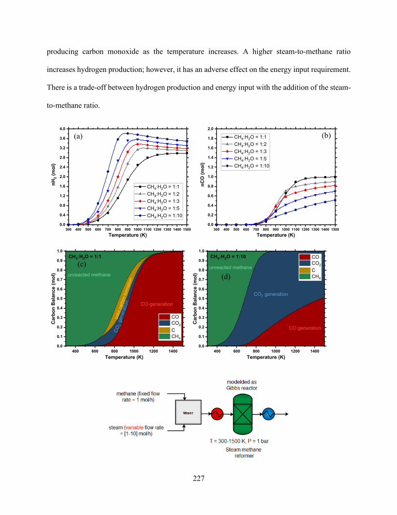
227
producing carbon monoxide as the temperature increases. A higher steam-to-methane ratio
increases hydrogen production; however, it has an adverse effect on the energy input requirement.
There is a trade-off between hydrogen production and energy input with the addition of the steam-
to-methane ratio.
300 400 500 600 700 800 900 1000 1100 1200 1300 1400 15000.0
0.4
0.8
1.2
1.6
2.0
2.4
2.8
3.2
3.6
4.0
nH2 (
mol
)
Temperature (K)
CH4:H2O = 1:1 CH4:H2O = 1:2 CH4:H2O = 1:3 CH4:H2O = 1:5 CH4:H2O = 1:10
300 400 500 600 700 800 900 1000 1100 1200 1300 1400 15000.0
0.2
0.4
0.6
0.8
1.0
1.2
1.4
1.6
1.8
2.0
nCO
(mol
)
Temperature (K)
CH4:H2O = 1:1 CH4:H2O = 1:2 CH4:H2O = 1:3 CH4:H2O = 1:5 CH4:H2O = 1:10
400 600 800 1000 1200 14000.0
0.1
0.2
0.3
0.4
0.5
0.6
0.7
0.8
0.9
1.0
Car
bon
Bal
ance
(mol
)
Temperature (K)
CO CO2
C CH4
unreacted methane
solid
car
bon
form
atio
n
CO generation
CO2
gene
ratio
n
CH4:H2O = 1:1
400 600 800 1000 1200 14000.0
0.1
0.2
0.3
0.4
0.5
0.6
0.7
0.8
0.9
1.0
Car
bon
Bal
ance
(mol
)
Temperature (K)
CO CO2
C CH4
unreacted methane
CO generation
CO2 generation
CH4:H2O = 1:10
(a) (b)
(c) (d)

228
Figure 7.2. Effect of CH4:H2O ratio on conversion, syngas yield, CO2 and H2O generation, energy input, and carbon deposition in SMR (P = 1 bar).
7.5.1.2 POX
As in SMR, in POX, increasing the temperature increases CH4 conversion, H2 generation,
and CO generation and reduces the production of CO2 (Figure 7.3). The maximum H2/CO ratio of
2:1 in this route is achieved at a higher temperature than the SMR ratio of 3:1 is. At higher oxygen-
to-methane ratios, complete combustion is dominant, which reduces the CO and H2 yield and
increases the generation of H2O and CO2. In our analysis, the oxygen-to-methane ratio (O:C)
varied between 0.25:1 and 1:1. The complete conversion of oxygen took place during partial
oxidation and started to decrease as the O:C ratio approached 2:1. Above the 2:1 ratio, complete
combustion occurred, and CO2 formation was favored over CO. The same trend was evident for
H2 at higher O:C ratios, favoring H2O production rather than H2. Due to the exothermic nature of
this reaction, a higher O:C ratio increased the energy output (Figure 7.3). Solid carbon formation
was suppressed by increasing the O:C ratio, enabling the reactor to operate at a relatively low
temperature. To maintain the syngas ratio above 2:15, this study used WGS to increase hydrogen
composition.5 The syngas was first heated to 572 °C with co-fed steam to WGS. The steam flow
rate was manipulated to adjust the syngas ratio to the desired value of 2.15.

229
Figure 7.3. Effects of CH4:O2 ratio on conversion, syngas yield waste production, energy input, and carbon deposition in POX (P = 1 bar).
300 400 500 600 700 800 900 1000 1100 1200 1300 1400 15000.0
0.2
0.4
0.6
0.8
1.0
1.2
1.4
1.6
1.8
2.0nH
2 (m
ol)
Temperature (K)
CH4:O2 = 1:0.25 CH4:O2 = 1:0.50 CH4:O2 = 1:0.75 CH4:O2 = 1:1
300 400 500 600 700 800 900 1000 1100 1200 1300 1400 15000.0
0.2
0.4
0.6
0.8
1.0
1.2
1.4
1.6
1.8
2.0
nCO
(mol
)
Temperature (K)
CH4:O2 = 1:0.25 CH4:O2 = 1:0.50 CH4:O2 = 1:0.75 CH4:O2 = 1:1
400 600 800 1000 1200 14000.0
0.2
0.4
0.6
0.8
1.0
Car
bon
Bal
ance
(mol
)
Temperature (K)
CO CO2
C CH4
unreacted methanesolid carbon formation
CO generation
CO2 generation
CH4:O2 = 1:0.25
400 600 800 1000 1200 14000.0
0.2
0.4
0.6
0.8
1.0
Car
bon
Bal
ance
(mol
)
Temperature (K)
CO CO2
C CH4
unreacted methane
solid carbon formationCO generation
CO2 generation
CH4:O2 = 1:0.75
(a) (b)
(c) (d)
(e)

230
7.5.1.3 DRM
The conversion of CH4 and CO2 were assessed over a wide range of temperatures between
300 and 1,500 K (Figure 7.4). A narrower temperature range has been already studied by
Nematollahi et al.28 The conversion of CH4 and CO2 increased as the temperature increased. In the
DRM process, the generation of hydrogen and carbon monoxide is favored at high temperatures,
similar to the SMR and POX processes (Figure 7.4). The significant difference in this process is
that the H2/CO ratio is lower than that of the other reforming technologies (close to 1:1) at an initial
feed ratio of CH4:CO2 = 1. As the ratio starts to increase (CH4:CO2), the ratio of syngas (H2:CO)
decreases, reaching a minimum (close to 1:0.2) at CH4:CO2 = 1:5. Higher temperatures help to
suppress carbon formation (Figure 7.4 c and d). This is consistent with previous studies on Gibbs
minimization free energy methods.21,50 Increasing the temperature increases the hydrogen yield in
low syngas ratios, whereas it exhibits a slight rise followed by a decreasing trend at higher syngas
ratios. As in SMR and POX, increasing the oxidizer (H2O, O2, or CO2) increases the conversion
of CH4. SMR and DRM have opposite trends with respect to H2 and CO generation; with more
CO2 in the feed, CO generation increases while H2 generation decreases. The carbon monoxide
domination described by the endothermic RWGS (Eq. 9), which increases CO2 in the feed, may
intensify the RWGS, resulting in partial consumption of the hydrogen. Although the amount of
carbon dioxide increases in the reactor outlet with the increasing CH4:CO2 ratio of the feed, the
discrepancy among the weight of CO2 percentage in the feed and yield decreases. The limitation
of the syngas ratio allows the reformer to operate in a parallel combination of DRM with SMR or
DRM with POX. A higher syngas ratio can be achieved by operating the reformer at higher
temperatures (>1,373 K).

231
Figure 7.4. Effects of CH4:CO2 ratio on conversion, syngas yield, CO2 generation, and carbon deposition in DRM (P = 1 bar).
400 600 800 1000 1200 14000.0
0.2
0.4
0.6
0.8
1.0
1.2
1.4
1.6
1.8
2.0
Car
bon
Bal
ance
(mol
)
Temperature (K)
CO CO2
C CH4
unreacted methane
solid carbon formation
CO generation
unreacted CO2
CH4:CO2 = 1:1
400 600 800 1000 1200 14000
1
2
3
4
5
6
Car
bon
Bal
ance
(mol
)
Temperature (K)
CO CO2
C CH4
unreacted methanesolid carbon formation
CO generationunreacted CO2
CH4:CO2 = 1:5
(a) (b)
(c) (d)
(e)

232
7.5.1.4 ATR
Figure 7.5 shows the effect of adding different H2O:O2 ratios to the ATR reformer and the
effect on the yield of the reactor (H2, CO, and energy load). In an autothermal reformer, a higher
S:C ratio can operate at 0.6–0.9, which allows ATR to produce a higher H2/CO ratio than does
POX. Various scenarios were executed in Aspen to determine the effect of adding an oxidizer
(H2O or O2) to ATR (Figure 7.5). It was noted that the addition of H2O or O2 increases the
conversion of methane in different H2 and CO yield ratios. The partial oxidation reaction was more
favorable than SMR was because of the more exothermic nature of this reaction, which explains
the effect on O2 conversion. The addition of an O2 oxidizer increased the amount of CO, and the
addition of H2O increased the amount of H2 produced. The enrichment of hydrogen at higher
H2O:O2 ratios is expressed by the WGS (Eq. 2). The addition of oxygen may increase the
exothermicity of the reaction in most cases; this addition of O2 reaches maximum exothermicity
when it is executed at higher O2:H2O ratios (similar to the operating conditions of POX).
1.7
1.8
1.9
2.1
2.2
2.3
2.52.6
2.7
2.8
3.0
3.13.2
3.4
0.0 0.2 0.4 0.6 0.8 1.01.0
1.5
2.0
2.5
3.0
3.5
4.0
nH2O
(mol
)
nO2 (mol)
1.61.71.81.92.12.22.32.52.62.72.83.03.13.23.43.5
nH2 (mol)
High hydrogen yield
1bar, 1000 Kni CH4 = 1
0.680.72
0.260.30
0.68
0.64
0.34
0.60
0.38
0.56
0.53
0.410.49
0.45
0.0 0.2 0.4 0.6 0.8 1.01.0
1.5
2.0
2.5
3.0
3.5
4.0
nH2O
(mol
)
nO2 (mol)
0.22
0.26
0.30
0.34
0.38
0.41
0.45
0.49
0.53
0.56
0.60
0.64
0.68
0.72
0.75nCO (mol)
High carbon monoxide yield
1bar, 1000 Kni CH4 = 1
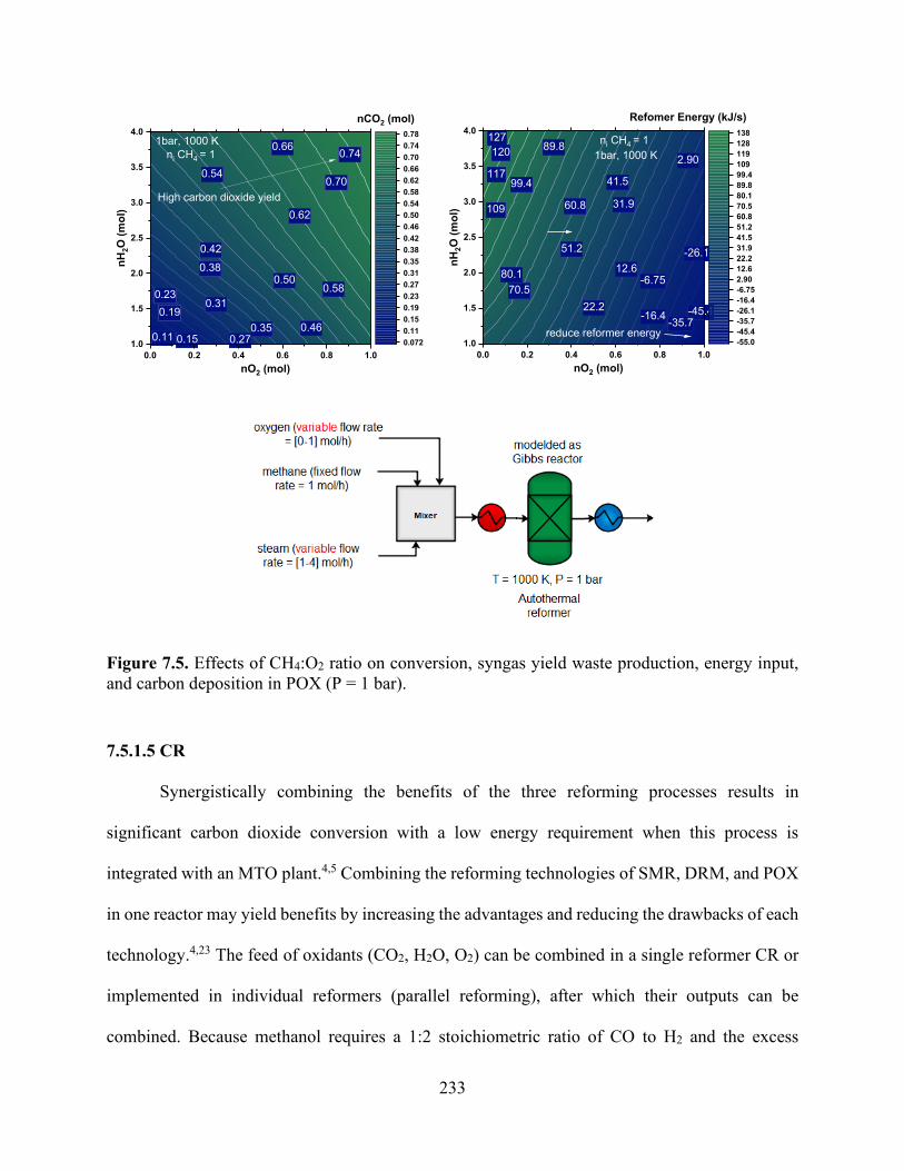
233
Figure 7.5. Effects of CH4:O2 ratio on conversion, syngas yield waste production, energy input, and carbon deposition in POX (P = 1 bar).
7.5.1.5 CR
Synergistically combining the benefits of the three reforming processes results in
significant carbon dioxide conversion with a low energy requirement when this process is
integrated with an MTO plant.4,5 Combining the reforming technologies of SMR, DRM, and POX
in one reactor may yield benefits by increasing the advantages and reducing the drawbacks of each
technology.4,23 The feed of oxidants (CO2, H2O, O2) can be combined in a single reformer CR or
implemented in individual reformers (parallel reforming), after which their outputs can be
combined. Because methanol requires a 1:2 stoichiometric ratio of CO to H2 and the excess
0.11 0.15
0.74
0.190.23
0.70
0.27
0.31
0.35
0.66
0.38
0.62
0.42
0.46
0.580.50
0.54
0.0 0.2 0.4 0.6 0.8 1.01.0
1.5
2.0
2.5
3.0
3.5
4.0nH
2O (m
ol)
nO2 (mol)
0.0720.110.150.190.230.270.310.350.380.420.460.500.540.580.620.660.700.740.78
nCO2 (mol)
High carbon dioxide yield
1bar, 1000 Kni CH4 = 1
-45.4-35.7
-26.1
-16.4
-6.75
2.90
12.6
22.2
31.9
41.5
51.2
60.8
70.580.1
89.8
99.4
109
117
120127
0.0 0.2 0.4 0.6 0.8 1.01.0
1.5
2.0
2.5
3.0
3.5
4.0
nH2O
(mol
)
nO2 (mol)
-55.0-45.4-35.7-26.1-16.4-6.752.9012.622.231.941.551.260.870.580.189.899.4109119128138
Refomer Energy (kJ/s)
reduce reformer energy
1bar, 1000 Kni CH4 = 1

234
hydrogen produced from SMR, CO2 is injected to react with methane through DRM (Eq. 6). The
overall reaction of the process can be achieved by combining the individual reactions (Eqs. 1 and
6), and this is then multiplied by a coefficient that ultimately yields the desired product (methanol).
The combination of SMR and DRM that should produce the 1:2 stoichiometric ratio of CO to H2
is as follows:
3𝐶𝐶𝐻𝐻4 + 2𝐻𝐻2𝑂𝑂 + 𝐶𝐶𝑂𝑂2 → 4𝐶𝐶𝑂𝑂 + 8𝐻𝐻2 → 4𝐶𝐶𝐻𝐻3𝑂𝑂𝐻𝐻 (14)
In addition to the combination of SMR and DRM, O2 was added to the reformer to use the
energy released from the incomplete reaction of methane in the POX reactor (Eqs. 3, 4, and 5).51
The addition of O2 to the feed increased CH4 conversion, especially at a temperature below 1,100
K (Figure 7.6 c and d) because CH4 became a limiting reactant and was consumed by both POX
and DRM. The addition of O2 increased CH4 conversion, but it also reduced CO2 conversion, as
shown in Figure 7.6 (c and d) due to the reaction of methane oxidation, which hindered the DRM
reaction (Eq. 6). The combination of SMR and DRM achieved a syngas ratio of 2.25 (Figure 6 a),
whereas a combination of POX, SMR, and DRM generated a 1.5 syngas ratio (Figure 7.6 b). The
presence of O2 in the combined reformer was shown to increase conversion of CH4 and CO2.28
Song reported catalytic tri-reforming of methane achieved high conversion (>97%) and high CO2
conversion (roughly 80%) to produce syngas with H2:CO = 1.5–2.0 over a Ni catalyst at 1,130–
1,273 K and 1 bar without carbon formation on the catalyst.22 Water formation increased as more
O2 was added to this process, implying that with the addition of high quantities of O2, CH4 tends
to convert into H2O and CO2 instead of CO and H2. The addition of O2 reduced the ratio of H2:CO
at low temperature due to the influence of POX reactions (Eq. 3) and RWGS (Eq. 9), whereas at a
higher temperature, the syngas ratio was dictated by DRM (Eq. 6).52 Increasing O2 content caused
a considerable decrease in CO2 conversion due to the predominance of the reaction of CH4 total

235
combustion (Eq. 5), which formed CO2 and H2O.53 However, carbon formation was reduced to a
minimum at 1,000 K when O2 was added compared to the formation in the cases of DRM and
SMR (Figure 7.6 c and d). In this combined reactor was demonstrated the competition of the two
oxidants (O2 and CO2) to be the oxidant agent for CH4, showing that O2 was consumed in all
conditions, whereas CO2 conversion depended on temperature and the addition of O2. Overall, the
optimal condition of this section was based on the maximization of CH4 conversion and the
production of a suitable H2/CO ratio for methanol synthesis. This comparison illustrates the
importance of studying the reforming network configuration to optimize the interlink parameters.
Coupling POX with SMR and DRM can facilitate heat transfer between endothermic and
exothermic reactions.
300 400 500 600 700 800 900 1000 1100 1200 1300 1400 1500
0.00.51.01.52.02.53.03.54.04.55.05.56.06.57.07.58.0
nCH4 (i) = 3
nH2,n
CO
,nC
O2,n
C,n
CH
4 (m
ol)
Temperature (K)
H2
CO CO2
C CH4
H2/CO ratioOptimum syngas ratio
CO
H2
nCO2 (i) = 1
nH2O (i) = 2
300 400 500 600 700 800 900 1000 1100 1200 1300 1400 15000.00.51.01.52.02.53.03.54.04.55.05.56.06.57.07.58.0
nCH4 (i) = 3
nH2,n
CO
,nC
O2,n
C,n
CH
4 (m
ol)
Temperature (K)
H2
CO CO2
C CH4
H2O
H2/CO ratio
CO
H2
nCO2 (i) = 1
nH2O (i) = 2
nO2 (i) = 0.5
(a) (b)
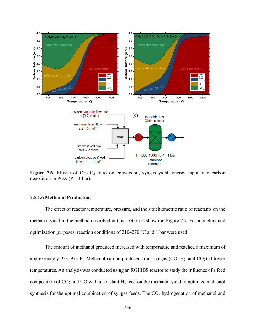
236
Figure 7.6. Effects of CH4:O2 ratio on conversion, syngas yield, energy input, and carbon deposition in POX (P = 1 bar).
7.5.1.6 Methanol Production
The effect of reactor temperature, pressure, and the stoichiometric ratio of reactants on the
methanol yield in the method described in this section is shown in Figure 7.7. For modeling and
optimization purposes, reaction conditions of 210–270 °C and 1 bar were used.
The amount of methanol produced increased with temperature and reached a maximum of
approximately 923–973 K. Methanol can be produced from syngas (CO, H2, and CO2) at lower
temperatures. An analysis was conducted using an RGIBBS reactor to study the influence of a feed
composition of CO2 and CO with a constant H2 feed on the methanol yield to optimize methanol
synthesis for the optimal combination of syngas feeds. The CO2 hydrogenation of methanol and
400 600 800 1000 1200 14000.0
0.5
1.0
1.5
2.0
2.5
3.0
3.5
4.0C
arbo
n B
alan
ce (m
ol)
Temperature (K)
CO CO2
C CH4
unreacted methane
solid carbon formation
CO generation
unreacted CO2
CH4:H2O:CO2 = 3:2:1
400 600 800 1000 1200 14000.0
0.5
1.0
1.5
2.0
2.5
3.0
3.5
4.0
Car
bon
Bal
ance
(mol
)
Temperature (K)
CO CO2
C CH4
unreacted methane
solid carbon formation CO generation
unreacted CO2
CH4:H2O:CO2:O2 = 3:2:1:0.5(c) (d)
(e)

237
the RWGS reaction were found to be acting competitively. Methanol synthesis is an exothermic
reaction and RWGS is endothermic, and RWGS dominated the process at higher temperatures. By
increasing the pressure, CO selectivity decreased while methanol selectivity increased. This
resulted in CO hydrogenation of methanol being more favorable than CO2 hydrogenation.
Methanol yield increased with increasing CO concentration in the feed, which decreased the
selectivity of forming CO from RWGS due to the presence of CO in the feed. Due to the low
equilibrium conversion to methanol, the recycling of syngas is necessary. As Figure 7.7 illustrates,
CO2 conversion decreased with the addition of CO and even became negative at high CO
concentrations. This was due to the WGS reaction, which produced additional CO2 in the presence
of CO. H2 conversion increased with increases in the addition of CO.
Figure 7.7 (c) shows the two reformers and methanol synthesis reactors that were placed
in a series. The effect of varying reformer inlet conditions on the outlet of the methanol reactor
was analyzed. The initial feed ratios of methane, water, and carbon dioxide were similar to the
ratio that was used in the combined reformer in Figure 7.6 (a and b). The results of using these
ratios are presented in Figure 7.7 (c and d). As shown in Figure 7.7, a maximum of 2.1 moles of
methanol was achieved at 373 K and 30 bar. A similar yield was obtained by the trade-off between
pressure and temperature.

238
0.91
0.84
0.77
0.70
0.63
0.56
0.49
0.42
0.35
0.28
0.210.14
0.0700.0 0.5 1.0 1.5 2.0 2.5 3.0 3.5 4.0
0.0
0.5
1.0
1.5
2.0
2.5
3.0
3.5
4.0nC
O2 (
mol
)
nCO (mol)
0.00
0.07
0.14
0.21
0.28
0.35
0.42
0.49
0.56
0.63
0.70
0.77
0.84
0.91
0.98
CH3OH(mol)
nH2 (i) = 2 mol373 K, 10 bar
0.72
0.630.54
0.45
0.36
0.27
0.180.090
1.0 1.5 2.0 2.5 3.0 3.5 4.00.0
0.5
1.0
1.5
2.0
2.5
3.0
3.5
4.0
nCO
2 (m
ol)
nH2 (mol)
0.000.090.180.270.360.450.540.630.720.810.900.991.081.171.261.35
CH3OH(mol)
nCO (i) = 0 mol373 K, 10 bar
(a)
(b)
(a)
(b)

239
Figure 7.7. (a) Effects of varying the CO:CO2 ratio with fixed H2 (nH2 = 2 mol) feed on the conversion of syngas to produce methanol at 373 K and 10 bar (b) effect if varying both CO and H2 in the reactor feed without CO2 as a co-feed at 373 K and 10 bar; (c) the same outlet composition obtained from the CR was used as a feed for methanol reactor.
375 400 425 450 475 500 525 5500.0
0.5
1.0
1.5
2.0
2.5
nCH
3OH
(mol
)
Temperature (K)
10 bar 20 bar 30 bar 40 bar 50 bar
CH4:H2O:CO2:O2=3:2:1:1
(c)
(c)

240
7.5.2 Material and Energy Balances
All three of the process designs discussed in the previous section were assessed for material
and energy balances, with results presented in Figure 7.8. The operating energy at different syngas
ratios of the SMR, DRM, and POX reformers is shown in Figure 7.8. The external heat input for
each recovery was calculated from the reactor energy balance. A positive HExternal means that the
reactor is endothermic and needs heat, and a negative HExternal means that the reactor is exothermic
and that heat must be removed. In this process, the highest demand for energy was from the SMR,
followed by DRM, and then the POX reactor. The energy of SMR indicated an increased use of
steam to obtain a higher syngas ratio, which increased the energy. SMR requires a heat supply and
produces syngas with H2:CO = 1:3, which is a relatively higher ratio than that of methanol
synthesis. POX is more economical to heat than SMR is, and the process does not require a catalyst.
Additionally, syngas with H2/CO = 1:2 is produced, which is ideal for methanol synthesis. The
results indicate that POX and ATR have higher efficiency than SMR in terms of energy usage.
However, POX requires high-purity O2, which requires an air separation plant to supply the
required O2. Compared with the high cost of SMR, an ATR reactor is moderately cheap to operate.
The ATR process is flexible, allowing for an option of oxygen or steam. However, the process
requires extensive operational control to ensure proper robust operations.
The need to have a transformative approach to optimize syngas production has been widely
investigated.4,5,23 Significant energy is lost in the current process in the SMR and DRM reactors
due to fuel consumption and low energy recovery. All methods involve high costs and are subject
to similar activation mechanisms. The combined reactor integrates SMR, POX, and DRM and has
the advantage of performing catalyst deactivation by oxidizing the coke, which increases catalyst
life and process efficiency. Thus, CR was chosen for the MTO plant, as illustrated in Figure 7.10.
241
Integrating SMR and POX with DRM is an encouraging concept whereby the undesired CO2
generated from the SMR and POX processes is exploited to reform the unreacted methane and
achieve autothermal reactions within the integration reactors. In the Aspen flowsheet, a methanol
synthesis reactor was modeled using a Continuous stirred-tank reactor (CSTR) with kinetic values
obtained from the literature. The methanol produced was then fed into the MTO reactor, which
was modeled in this case as three RSTOICH reactors to produce ethylene, propylene, and butene.
This split fraction allocated to each reactor was decided on the basis of experimental yields
illustrated in Table 7.1.8,44 Downstream compression and cryogenic energy separation were not
included in this study; however, in the conventional cracking process, they result in additional
energy loss. Higher ethane conversion can reduce compression and separation load. However, this
approach is not practical, owing to reaction limitations and the tendency of ethylene to undergo
secondary reactions that form coke on the tubes’ inner surfaces.54
In MTO, methanol is converted to ethylene, propylene, butene, and water in a set of net-
exothermic reactions. MTO offers overall process exothermicity because ethane conversion is not
limited by a reaction equilibrium, as is the case with steam cracking (Figure 7.9). However, the
low ethylene yield (<20% ethylene) and the considerable ethane by-products require intensive
downstream separation and the recycling of the unconverted methane and ethane.55,56 Figure 7.8
shows a section-wise comparison of energy consumption. The simulation indicates that the energy
demand is higher for steam cracking than for MTO. It should be noted that both MTO and steam
cracking processes require intensive separation and coproduce propylene and butene. These
coproducts can either be credited to the process as fuels or purified and sold as by-products.

242
Figure 7.8. Energy input for syngas production from various routes: (a) DRM, (b) SMR, (c) (POX), and (d) CR.
Figure 7.9. Energy input for ethane steam cracking.
300 400 500 600 700 800 900 1000 1100 1200 1300 1400 15000
40
80
120
160
200
240
280
320
360
Hea
t Loa
d (k
J/s)
Temperature (K)
CH4:H2O = 1:1 CH4:H2O = 1:2 CH4:H2O = 1:3 CH4:H2O = 1:5 CH4:H2O = 1:10
SMR Process
300 400 500 600 700 800 900 1000 1100 1200 1300 1400 1500-120
-100
-80
-60
-40
-20
0
20
40
60
Hea
t Loa
d (k
J/s)
Temperature (K)
CH4:O2 = 1:0.25 CH4:O2 = 1:0.50 CH4:O2 = 1:0.75 CH4:O2 = 1:1
POX Process
300 400 500 600 700 800 900 1000 1100 1200 1300 1400 1500-250
-200
-150
-100
-50
0
50
100
150
200
250
300
350
400
Hea
t Loa
d (k
J/s)
Temperature (K)
CH4:H2O:CO2 = 3:2:1 CH4:H2O:CO2:O2 = 3:2:1:0.5 CH4:H2O:CO2:O2 = 3:2:1:1 CH4:H2O:CO2:O2 = 3:2:1:2
SMR+DRM+POX Process
2 mol of O2 added
No O2 added
Incr
easi
ng e
xoth
erm
icity
1050 1100 1150 1200 1250
0
5
10
15
20
25
30
35
40
45
Hea
t Loa
d (k
J/s)
Temperature (K)
nC2H6 (i) = 1 molL = 4 m
Heat L
oad
Ethylen
e yiel
d
0.0
0.1
0.2
0.3
0.4
0.5
0.6
0.7
0.8
0.9
1.0
nC2H
4 (m
ol)
(a)
(b)
(c) (d)
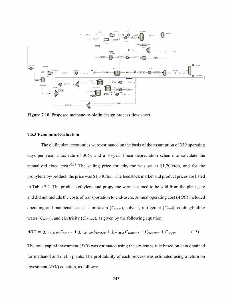
243
Figure 7.10. Proposed methane-to-olefin design process flow sheet.
7.5.3 Economic Evaluation
The olefin plant economics were estimated on the basis of the assumption of 330 operating
days per year, a tax rate of 30%, and a 10-year linear depreciation scheme to calculate the
annualized fixed cost.57,58 The selling price for ethylene was set at $1,200/ton, and for the
propylene by-product, the price was $1,340/ton. The feedstock market and product prices are listed
in Table 7.2. The products ethylene and propylene were assumed to be sold from the plant gate
and did not include the costs of transportation to end-users. Annual operating cost (AOC) included
operating and maintenance costs for steam (Csteam), solvent, refrigerant (Crefri), cooling/boiling
water (Cwater), and electricity (Celectric), as given by the following equation:
𝐴𝐴𝑂𝑂𝐶𝐶 = ∑ 𝐶𝐶𝑎𝑎𝑎𝑎𝑒𝑒𝑎𝑎𝑁𝑁LPS,MPS + ∑ 𝐶𝐶𝑤𝑤𝑎𝑎𝑎𝑎𝑒𝑒𝑁𝑁CW,BW + ∑ 𝐶𝐶𝑎𝑎𝑜𝑜𝑎𝑎𝑎𝑎𝑒𝑒𝑎𝑎𝑎𝑎MDEA + 𝐶𝐶𝑒𝑒𝑎𝑎𝑒𝑒𝑐𝑐𝑎𝑎𝑁𝑁𝑎𝑎𝑐𝑐 + 𝐶𝐶𝑁𝑁𝑒𝑒𝑜𝑜𝑁𝑁𝑎𝑎 (15)
The total capital investment (TCI) was estimated using the six-tenths rule based on data obtained
for methanol and olefin plants. The profitability of each process was estimated using a return on
investment (ROI) equation, as follows:

244
𝑅𝑅𝑂𝑂𝑅𝑅 = (𝐴𝐴𝑎𝑎𝑎𝑎𝑁𝑁𝑎𝑎𝑎𝑎 𝑎𝑎𝑎𝑎𝑐𝑐𝑜𝑜𝑁𝑁𝑒𝑒𝑎𝑎−𝑂𝑂𝑎𝑎𝑒𝑒𝑁𝑁𝑎𝑎𝑎𝑎𝑎𝑎𝑎𝑎𝑒𝑒 𝑐𝑐𝑜𝑜𝑎𝑎𝑎𝑎𝑎𝑎−𝐴𝐴𝑎𝑎𝑎𝑎𝑁𝑁𝑎𝑎𝑎𝑎𝑎𝑎𝑧𝑧𝑒𝑒𝑑𝑑 𝑜𝑜𝑎𝑎𝑥𝑥𝑒𝑒𝑑𝑑 𝑐𝑐𝑜𝑜𝑎𝑎𝑎𝑎)×(1−𝑎𝑎𝑎𝑎𝑥𝑥 𝑁𝑁𝑎𝑎𝑎𝑎𝑒𝑒)+Annualized fixed cost 𝑇𝑇𝐶𝐶𝑇𝑇
(16)
The cost of shale gas was assumed to be $3.50/kscf. The lifetime of the catalysts was not
considered as part of the operating cost estimation.
Table 7.2. Cost parameters for the economic evaluation of the process.
Item Best value
Shale gas $5.6/MMbtu
Ethane $0.50/gal
Ethylene $1,200/ton
Propane $1.00/gal
Butene $1.60/gal
Hydrogen $1.76/kg
Propylene $1,340/ton
Electricity $0.07/kWh
Based on the simulation results, capital costs and variable operating costs of most of the
process equipment (i.e., reactors, flash tanks, and distillation columns) in addition to fixed
operating costs for the plant (i.e., labor, insurance, and maintenance) were estimated using Aspen
Process Economic Analyzer. Vacuum pumps are not standard simulation blocks in Aspen, and
thus, they were analyzed separately. Feedstock and utilities were assumed to be available at the
prices listed in Table 7.3. The total capital and operating costs for the process are presented in
Table 7.4. For a base case plant size that is capable of processing 1,000 ton/yr−1 of methane, the
total installed equipment costs were $16.4 million.

245
Table 7.3. Process utilities and feedstock prices.
Methane purchase price ($ kscf−1)59 3.5
Grade 1 refrigerant 2.74 × 10⁻⁶
Cooling water ($ kg−1)a 3.08 × 10⁻⁵
Steam, 100 PSI ($ kg−1)a 0.0179
Fired heater, 1273K ($ kJ−1)a 4.2 × 10⁻⁶
Electricity ($ kg−1)a 0.0775 a Estimated using Aspen Process Economic Analyzer
Table 7.4. Total capital and operating costs for the methane-to-olefin plant.
Total Capital Cost [$MM] 17.54
Total Operating Cost [$MM/Year] 55.31
Total Raw Materials Cost [$MM/Year] 7.23
Total Utility Cost [$MM/Year] 4.92
Desired Rate of Return [Percent/Year] 20
Equipment Cost [$MM] 6.76
Total Installed Cost [$MM] 9.50
7.5.4 Energy Integration
The heat integration of each process design was investigated using Aspen Energy Analyzer.
Thermal pinch analysis was performed on the base case to identify the recovery of heat within the
process streams. Pinch analysis is a heat exchanger network (HEN) optimization algorithm that
can be used to reduce the energy consumption in a process by setting feasible energy targets to be
achieved by the optimization of the heat recovery systems, methods of energy supply, and process
conditions for a reduction in energy.60 The composite curve is achieved by summing all the heat
loads over a range of temperatures. The composite curve is presented in Figure 7.11. The process
had several heating and cooling duties. The heat exchanger took inlet stream and heated it to 1,000
246
K before it entered the CR reactor. The heat recovery exchangers cooled the syngas mixture stream
from the CR reactor to 323 K and then compressed the mixture to a pressure of 40 bar. The
condensed liquid was separated from the syngas stream in the flash column, and then the gas
stream was heated again in the methanol heat exchanger to 543 K before the stream entered the
methanol reactor. The product outlet was then sent to cool exchangers to cool them to 323 K. The
heat load for each of the types of equipment used in the process flow sheet is shown in Figure 7.5.
It was determined that the operating energy of this process can be reduced by using heat
integration. The minimum hot and cold utility requirements were 153 kJ/s and 12,230 kJ/s,
respectively. High values of hot utility were due to the large heating requirement of the fired heater
and reboiler. The high cold utility was due to the reactor effluent cooler and condenser. There was
potential for heat exchange in the temperature range of 273–1,000 K. Therefore, the composite
curve could be further optimized for the heat exchanger network to provide the lowest energy
consumption for the external utilities. Given these high energy values for the utilities, an integrated
case was developed to reduce the energy consumption from external sources by utilizing some of
the process heat. For this modification, the combined reactor effluent cooling duty was reduced.
The syngas leaving the reformer had a hot stream that could serve as effective heat recovery.
Figure 7.11 (c) shows the grand composite curve that was developed in the process. The
analysis shows that the target values can be reduced to minimal values. Cooling utilities can be
reduced by 39.3%, and the 98.5% heating requirement can be reduced by 95%. Such reductions in
energy requirements have the potential to provide savings equivalent to MM$2.79/year (Figure
7.13 and Table 7.6).
In addition to the heat exchange network, which is illustrated in Figure 11 (b), the methanol
reactor has the potential for mass and heat integration with a methane reformer reactor.24 The heat
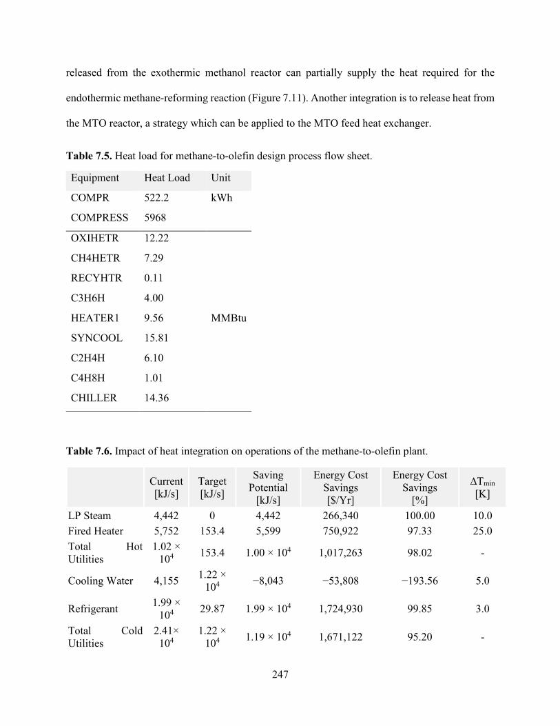
247
released from the exothermic methanol reactor can partially supply the heat required for the
endothermic methane-reforming reaction (Figure 7.11). Another integration is to release heat from
the MTO reactor, a strategy which can be applied to the MTO feed heat exchanger.
Table 7.5. Heat load for methane-to-olefin design process flow sheet.
Equipment Heat Load Unit
COMPR 522.2 kWh
COMPRESS 5968
OXIHETR 12.22
MMBtu
CH4HETR 7.29
RECYHTR 0.11
C3H6H 4.00
HEATER1 9.56
SYNCOOL 15.81
C2H4H 6.10
C4H8H 1.01
CHILLER 14.36
Table 7.6. Impact of heat integration on operations of the methane-to-olefin plant.
Current [kJ/s]
Target [kJ/s]
Saving Potential
[kJ/s]
Energy Cost Savings [$/Yr]
Energy Cost Savings
[%]
∆Tmin [K]
LP Steam 4,442 0 4,442 266,340 100.00 10.0 Fired Heater 5,752 153.4 5,599 750,922 97.33 25.0 Total Hot Utilities
1.02 × 10⁴ 153.4 1.00 × 10⁴ 1,017,263 98.02 -
Cooling Water 4,155 1.22 × 10⁴ −8,043 −53,808 −193.56 5.0
Refrigerant 1.99 × 10⁴ 29.87 1.99 × 10⁴ 1,724,930 99.85 3.0
Total Cold Utilities
2.41× 10⁴
1.22 × 10⁴ 1.19 × 10⁴ 1,671,122 95.20 -

248
Figure 7.11. Temperature−enthalpy change diagram for (a) the baseline and (b) integrated approaches and (c) the grand composite curve for heat integration of the methane-to-olefin plant.
(a) (b)
(c)
(a)

249
Figure 7.12. Heat exchanger network (HEN) diagram obtained using ASPEN Energy Analyzer, where red lines show hot streams and blue lines show cold streams for (a) the baseline and (b) the proposed heat integration network.
(b)

250
Figure 7.13. Effect of energy integration on heating and cooling requirements and carbon emissions.
7.5.5 Environmental Impact
CO2 emissions were analyzed in order to determine the effect on the atmosphere of each
operation. Based on actual CO2 emissions and energy-related emissions, the carbon emissions
were calculated. CO2 emissions can be directly generated by burning fuels. The CO2 equivalent of
outlet streams was obtained from Aspen Plus simulations, whereas CO2 emissions from the
consumption of electricity were calculated using a factor of 0.73 MT of CO2/MW.8 Emissions
from heating utilities were estimated using the Environmental Protection Agency’s energy
calculation method of stationary combustion.61 The resulting CO2 emissions of the process were
determined to be 6,433 kg/h. Combining DRM and SMR can produce syngas with H2:CO close to
a ratio of 2:1, resulting in minimal CO2 emissions. The analysis revealed the differences in the
environmental impact after applying energy integration resulted in a CO2 reduction from 6,433 to
43.2 kg/h.

251
7.6 Conclusion
Technical analyses for ethylene, propylene, and other products produced from methane
were presented. Four reforming technologies were analyzed to produce syngas: POX, SMR, ATR,
and CR. Of all the cases considered in this study, we found the case of using CR and MTO to be
the most promising route to produce ethylene with low energy demand and CO2 emissions. There
is a >50% reduction in the energy consumption for the proposed route compared with the
conventional reforming units. Aspen Plus was used to assess the performance of each option.
Thermodynamically, the equilibrium conversion of CH4, CO2, and O2 was preferred between 700
and 1,100 K. The highest yield of H2 was obtained at CH4/CO2 and CH4/O2 ratios of 1.0 and 4.0,
respectively, and a temperature of 1,100 K. The results show that POX and ATR have higher
efficiency than SMR does in terms of energy usage. The impact of each process on the carbon
footprint was evaluated, and the overall CO2 emissions for a specific H2/CO ratio were compared.
The comparisons indicate that DRM has a negative carbon footprint at a low syngas ratio of 1 and
below and more carbon emissions can be reduced through integrating heating and cooling utilities,
resulting in a CO2 from 6,433 to 43.2 kg/h.

252
7.7 References
1. World Energy Outlook 2019. (OECD, 2019). doi:10.1787/caf32f3b-en
2. York, A. P. E., Xiao, T., Green, M. L. H. & Claridge, J. B. Methane Oxyforming for
Synthesis Gas Production. Catal. Rev. 49, 511–560 (2007).
3. Martinez-Gomez, J. et al. Involving economic, environmental and safety issues in the
optimal purification of biobutanol. Process Saf. Environ. Prot. 103, 365–376 (2016).
4. Noureldin, M. M. B., Elbashir, N. O., Gabriel, K. J. & El-Halwagi, M. M. A process
integration approach to the assessment of CO2 fixation through dry reforming. ACS Sustain.
Chem. Eng. 3, 625–636 (2015).
5. Gabriel, K. J. et al. Targeting of the water-energy nexus in gas-to-liquid processes: A
comparison of syngas technologies. Ind. Eng. Chem. Res. 53, 7087–7102 (2014).
6. Ehlinger, V. M., Gabriel, K. J., Noureldin, M. M. B. & El-Halwagi, M. M. Process design
and integration of shale gas to methanol. ACS Sustain. Chem. Eng. 2, 30–37 (2014).
7. Julián-Durán, L. M., Ortiz-Espinoza, A. P., El-Halwagi, M. M. & Jiménez-Gutiérrez, A.
Techno-economic assessment and environmental impact of shale gas alternatives to
methanol. ACS Sustain. Chem. Eng. 2, 2338–2344 (2014).
8. Ortiz-Espinoza, A. P., Noureldin, M. M. B., El-Halwagi, M. M. & Jiménez-Gutiérrez, A.
Design, simulation and techno-economic analysis of two processes for the conversion of
shale gas to ethylene. Comput. Chem. Eng. 107, 237–246 (2017).
9. Jasper, S. & El-Halwagi, M. A techno-economic comparison between two methanol-to-
propylene processes. Processes 3, 684–698 (2015).
10. Pérez-Uresti, S. I., Adrián-Mendiola, J. M., El-Halwagi, M. M. & Jiménez-Gutiérrez, A.
Techno-economic assessment of benzene production from shale gas. Processes 5, 33

253
(2017).
11. Bao, B., El-Halwagi, M. M. & Elbashir, N. O. Simulation, integration, and economic
analysis of gas-to-liquid processes. Fuel Process. Technol. 91, 703–713 (2010).
12. An, Y. et al. Advances in direct production of value-added chemicals via syngas conversion.
Sci. China Chem. 60, 887–903 (2017).
13. Guo, X. et al. Direct, nonoxidative conversion of methane to ethylene, aromatics, and
hydrogen. Science (80-. ). 344, 616–619 (2014).
14. He, C. & You, F. Toward more cost-effective and greener chemicals production from shale
gas by integrating with bioethanol dehydration: Novel process design and simulation-based
optimization. AIChE J. 61, 1209–1232 (2015).
15. Bao, J., Yang, G., Yoneyama, Y. & Tsubaki, N. Significant Advances in C1 Catalysis:
Highly Efficient Catalysts and Catalytic Reactions. ACS Catal. 9, 3026–3053 (2019).
16. Spivey, J. J. & Hutchings, G. Catalytic aromatization of methane. Chem. Soc. Rev. 43, 792–
803 (2014).
17. Taifan, W. & Baltrusaitis, J. CH 4 conversion to value added products: Potential, limitations
and extensions of a single step heterogeneous catalysis. Appl. Catal. B Environ. 198, 525–
547 (2016).
18. Cho, W. et al. Optimal design and operation of a natural gas tri-reforming reactor for DME
synthesis. Catal. Today 139, 261–267 (2009).
19. Kalamaras, C. M. & Efstathiou, A. M. Hydrogen Production Technologies: Current State
and Future Developments. Conf. Pap. Energy 2013, 1–9 (2013).
20. Wilhelm, D. J., Simbeck, D. R., Karp, A. D. & Dickenson, R. L. Syngas production for gas-
to-liquids applications: Technologies, issues and outlook. Fuel Process. Technol. 71, 139–

254
148 (2001).
21. Rostrup-Nielsen, J. R. & Bak Hansen, J. H. CO2-reforming of methane over transition
metals. J. Catal. 144, 38–49 (1993).
22. Song, C. & Pan, W. Tri-reforming of methane: a novel concept for catalytic production of
industrially useful synthesis gas with desired H2/CO ratios. Catal. Today 98, 463–484
(2004).
23. Noureldin, M. M. B., Elbashir, N. O. & El-Halwagi, M. M. Optimization and Selection of
Reforming Approaches for Syngas Generation from Natural/Shale Gas. Ind. Eng. Chem.
Res. 53, 1841–1855 (2014).
24. Godini, H. R. et al. Techno-economic analysis of integrating the methane oxidative
coupling and methane reforming processes. Fuel Process. Technol. 106, 684–694 (2013).
25. Martinez-Gomez, J., Nápoles-Rivera, F., Ponce-Ortega, J. M. & El-Halwagi, M. M.
Optimization of the production of syngas from shale gas with economic and safety
considerations. Appl. Therm. Eng. 110, 678–685 (2017).
26. Niziolek, A. M., Onel, O. & Floudas, C. A. Production of Benzene, Toluene, and the
Xylenes from Natural Gas via Methanol. Comput. Aided Chem. Eng. 38, 2349–2354 (2016).
27. He, C. & You, F. Shale gas processing integrated with ethylene production: Novel process
designs, exergy analysis, and techno-economic analysis. Ind. Eng. Chem. Res. 53, 11442–
11459 (2014).
28. Nematollahi, B., Rezaei, M. & Khajenoori, M. Combined dry reforming and partial
oxidation of methane to synthesis gas on noble metal catalysts. Int. J. Hydrogen Energy 36,
2969–2978 (2011).
29. Meissner, H. P., Kusik, C. L. & Dalzell, W. H. Equilibrium composition with multiple

255
reactions. Ind. Eng. Chem. Fundam. 8, 659–665 (1969).
30. Foust, T. D., Aden, A., Dutta, A. & Phillips, S. An economic and environmental comparison
of a biochemical and a thermochemical lignocellulosic ethanol conversion processes.
Cellulose 16, 547–565 (2009).
31. Phillips, S., Aden, A., Jechura, J. & Dayton, D. Thermochemical ethanol via indirect
gasification and mixed alcohol synthesis of lignocellulosic biomass. Ethanol Biofuel
Production (National Renewable Energy Lab.(NREL), Golden, CO (United States), 2010).
32. Asaro, M., Smith, R. M. & Davis, B. H. Gas to Liquid Technologies. in Encyclopedia of
Sustainability Science and Technology (ed. Meyers, R. A.) 1–48 (Springer New York,
2017). doi:10.1007/978-1-4939-2493-6_72-3
33. Steynberg, A. & Dry, M. Fischer-Tropsch Technology. (Elsevier Science, 2004).
34. Aasberg-Petersen, K. et al. Natural gas to synthesis gas - Catalysts and catalytic processes.
J. Nat. Gas Sci. Eng. 3, 423–459 (2011).
35. Snoeck, J. W., Froment, G. F. & Fowles, M. Steam/CO2 reforming of methane. Carbon
filament formation by the Boudouard reaction and gasification by CO2, by H2, and by
steam: Kinetic study. Ind. Eng. Chem. Res. 41, 4252–4265 (2002).
36. Tijm, P. J. A., Waller, F. J. & Brown, D. M. Methanol technology developments for the
new millennium. Appl. Catal. A Gen. 221, 275–282 (2001).
37. Vanden Bussche, K. M. & Froment, G. F. A steady-state kinetic model for methanol
synthesis and the water gas shift reaction on a commercial Cu/ZnO/Al2O3 catalyst. J. Catal.
161, 1–10 (1996).
38. Arora, S. S. & Bhan, A. The critical role of methanol pressure in controlling its transfer
dehydrogenation and the corresponding effect on propylene-to-ethylene ratio during

256
methanol-to-hydrocarbons catalysis on H-ZSM-5. J. Catal. 356, 300–306 (2017).
39. Lee, Y. J., Baek, S. C. & Jun, K. W. Methanol conversion on SAPO-34 catalysts prepared
by mixed template method. Appl. Catal. A Gen. 329, 130–136 (2007).
40. Chen, J. Q., Bozzano, A., Glover, B., Fuglerud, T. & Kvisle, S. Recent advancements in
ethylene and propylene production using the UOP/Hydro MTO process. Catal. Today 106,
103–107 (2005).
41. Mokrani, T. & Scurrell, M. Gas conversion to liquid fuels and chemicals: The methanol
route-catalysis and processes development. Catal. Rev. - Sci. Eng. 51, 1–145 (2009).
42. Onel, O., Niziolek, A. M. & Floudas, C. A. Optimal Production of Light Olefins from
Natural Gas via the Methanol Intermediate. Ind. Eng. Chem. Res. 55, 3043–3063 (2016).
43. Khare, R., Millar, D. & Bhan, A. A mechanistic basis for the effects of crystallite size on
light olefin selectivity in methanol-to-hydrocarbons conversion on MFI. J. Catal. 321, 23–
31 (2015).
44. Vora, B. V. et al. Economic route for natural gas conversion to ethylene and propylene. in
Studies in Surface Science and Catalysis 107, 87–98 (Elsevier, 1997).
45. Wilson, S. & Barger, P. The characteristics of SAPO-34 which influence the conversion of
methanol to light olefins. Microporous Mesoporous Mater. 29, 117–126 (1999).
46. Gao, Y. et al. Recent Advances in Intensified Ethylene Production—A Review. ACS Catal.
9, 8592–8621 (2019).
47. Gradassi, M. J. & Wayne Green, N. Economics of natural gas conversion processes. Fuel
Process. Technol. 42, 65–83 (1995).
48. Zaman, J. Oxidative processes in natural gas conversion. Fuel Process. Technol. 58, 61–81
(1999).
257
49. Fogler, H. S. Essentials of Chemical Reaction Engineering. Focus on Catalysts 2017,
(Pearson Education, 2017).
50. Fan, M. S., Abdullah, A. Z. & Bhatia, S. Catalytic technology for carbon dioxide reforming
of methane to synthesis gas. ChemCatChem 1, 192–208 (2009).
51. O’Connor, A. M. & Ross, J. R. H. The effect of O2 addition on the carbon dioxide reforming
of methane over Pt/ZrO2 catalysts. Catal. Today 46, 203–210 (1998).
52. Souza, M. M. V. M. & Schmal, M. Combination of carbon dioxide reforming and partial
oxidation of methane over supported platinum catalysts. Appl. Catal. A Gen. 255, 83–92
(2003).
53. Tomishige, K., Nurunnabi, M., Maruyama, K. & Kunimori, K. Effect of oxygen addition to
steam and dry reforming of methane on bed temperature profile over Pt and Ni catalysts.
Fuel Process. Technol. 85, 1103–1120 (2004).
54. Neal, L. M., Haribal, V. P. & Li, F. Intensified Ethylene Production via Chemical Looping
through an Exergetically Efficient Redox Scheme. iScience 19, 894–904 (2019).
55. Ahari, J. S., Sadeghi, M. T. & Zarrinpashne, S. Effects of operating parameters on oxidative
coupling of methane over Na-W-Mn/SiO2 catalyst at elevated pressures. J. Nat. Gas Chem.
20, 204–213 (2011).
56. Elkins, T. W. & Hagelin-Weaver, H. E. Characterization of Mn–Na2WO4/SiO2 and Mn–
Na2WO4/MgO catalysts for the oxidative coupling of methane. Appl. Catal. A Gen. 497,
96–106 (2015).
57. El-Halwagi, M. M. Overview of Process Economics. in Sustainable Design Through
Process Integration (ed. El-Halwagi, M. M. B. T.-S. D. T. P. I.) 15–61 (Butterworth-
Heinemann, 2012). doi:10.1016/b978-1-85617-744-3.00002-3

258
58. Peters, M. S. & Peters, J. I. Plant design and economics for chemical engineers. Engineering
Economist 5, (McGraw-Hill New York, 1959).
59. Davis, R. et al. Process Design and Economics for the Conversion of Lignocellulosic
Biomass to Hydrocarbons: Dilute-Acid and Enzymatic Deconstruction of Biomass to
Sugars and Biological Conversion of Sugars to Hydrocarbons. National Renewable Energy
Laboratory-NREL (National Renewable Energy Lab.(NREL), Golden, CO (United States),
2013). doi:10.2172/1107470
60. Linnhoff, B. & Boland, D. A user guide on process integration for the efficient use of
energy. (Elsevier, 1982). doi:10.1016/0300-9467(83)80027-6
61. Albina, D. O. & Themelis, N. J. Emissions from Waste-to-Energy: A Comparison with
Coal-fired Power Plants. in Energy Conversion and resources - 2003 169–184 (American
Society of Mechanical Engineers Digital Collection, 2003). doi:10.1115/imece2003-55295
Copyright © 2022 FDOKUMEN